web: Instruction Manual · PDF file · 2016-09-21METRIC EN 14399-9 1 INTRODUCTION...
17
® TurnaSure LL InstructionManual forinstalling Preloaded(HSFG)Bolting with TurnaSure ® DIRECTTENSIONINDICATORS CEMarkedEN14399-9 © 2011 TurnSure LLC. All Rights Reserved. ANDREWS FASENERS LIMIED Latchmore Park, Latchmore Rd LS12 6DN, Leeds, United Kingdom phone: +44 (0) 113 246 9992 emai: [email protected] web: www.andrewsfasteners.uk
-
Upload
hoangquynh -
Category
Documents
-
view
215 -
download
2
Transcript of web: Instruction Manual · PDF file · 2016-09-21METRIC EN 14399-9 1 INTRODUCTION...

®
TurnaSure LLC
Instruction Manualfor installing
Preloaded (HSFG) Boltingwith
TurnaSure®
DIRECT TENSION INDICATORSCE Marked EN 14399-9
© 2011 TurnaSure LLC. All Rights Reserved.
ANDREWS FASTENERS LIMITEDLatchmore Park, Latchmore Rd
LS12 6DN, Leeds, United Kingdom
phone: +44 (0) 113 246 9992email: [email protected] web: www.andrewsfasteners.uk
TABLE OF CONTENTS
Introduction .................................................................................... 1
Theory of Preloaded Bolting Assemblies ....................................... 2
Tightening of Preloaded Assemblies.............................................. 3
Recommended DTI Assembly Installation Procedure ................... 4
Configurtion of DTI Preloaded Assemblies .................................... 6
Inspection of Assembled DTIs ....................................................... 11
Lubrication...................................................................................... 14
(July 2011 edition)TurnaSure LLCInternational Headquarters Phone: 215-750-1300340 E. Maple Avenue, Suite 206 Fax: 215-750-6300Langhorne, PA 19047 U.S.A. Website: www.turnasure.com
®
© 2011 TurnaSure LLC. All Rights Reserved.

METRIC EN 14399-91
INTRODUCTION
Preloaded Bolting assemblies otherwise known as ‘HighStrength Friction Grip Bolting’ are well established as an economicaland efficient method of providing connections in structural steelwork.
The rules for the use of Preloaded Bolting assemblies in steelstructures within Europe are defined in the recently developedEuropean Standards EN 1090-2 and EN 1993 (Eurocode 3).
Preloaded Bolting assemblies are tightened to produce apreload in the bolt which generates frictional resistance to movementbetween the plies of the connection. These assemblies can be usedin any type of structural steelwork joint, but more especially where thefollowing factors apply:
1. Fatigue 2. Vibration 3. Load Reversal 4. Dimensional Stability
The basic requirement of the Preloaded Bolting assembly is thata correct and reproducible preload in the bolt is achieved.
Direct Tension Indicator (DTI) assemblies, a form of PreloadedBolting assembly, are one of several such methods of ensuring thatthe preload is consistently achieved. Among the many advantages ofthe system is the repeatable bolt preload that can be achievedregardless of the lubrication that has been applied to the boltingassembly.
This booklet is written for Engineers, Supervisors, Inspectorsand Erection Staff, to assist them in the correct installation of DTI assemblies.
TurnaSure LLC has many years of experience in the supply ofDTIs for use in structural steelwork, both in the UK, USA and EU, andcan provide a range of technical support including technical reportsand information on fastener specifications.
© 2011 TurnaSure LLC. All Rights Reserved.

2METRIC EN 14399-9
THEORY OF PRELOADED BOLTING ASSEMBLIES
The principle of Preloaded bolted connections relies upon tensioning each bolt in the connection to a specified minimumpreload so that the required clamping force will be induced at theconnection interface. Shear loads are then transferred by frictionalresistance at the joint interface rather than by bearing on the boltshanks and hole faces. In this type of connection there will be no movement of the connected materials when the connection issubjected to these loads.
When axial tensile loads are applied to the bolt through the bolted connection, preloading of the connection to a specified minimum is also important, particularly if the loads are cyclical andcould induce loosening or fatigue failure of the bolts. The clampingforce developed at the specified minimum bolt preload should begreater than the applied loads. This will prevent the plies from separating or the bolts from developing any significant increase inaxial tensile stress over the installed preload stress.
© 2011 TurnaSure LLC. All Rights Reserved.

TIGHTENING OF PRELOADED ASSEMBLIES
The essential requirement for preloaded connections is that the individual bolts are correctly tightened to the specified minimumpreload; EN 1993.1.8 (Eurocode 3) specifies that to develop the necessary clamp force in the connection each bolt must bepreloaded to 70% of the nominal bolt tensile strength.
The permitted methods of preloading in EN 1090-2 are dependent on either movement of the nut along the bolt thread by aspecified amount or the application of a calculated value of torque(turning moment) to the nut.
Methods that depend on displacement of the nut:1. The DTI method depends on the deformation of protrusions
that have been extruded from the face of a washer. The DTIis calibrated so that when a specified average gap is reachedthe required preload is achieved.
2. The Highways Agency part-turn method requires each bolt tobe tightened by torque to bring the steelwork into contact(each bolt diameter uses a different torque value). A part-turn, a minimum of a half turn, is then applied to develop the required preload.
Methods that depend on the application of torque:1. The Combined method requires the bolt to be torqued to 75%
of the required preload; the required torque is calculated fromdata obtained from the EN 14399-2 – Fitness for Purposetest. A small part-turn, less than one third turn, is then appliedto develop the required preload.
2. The Torque Control method again uses a value of torque calculated from data obtained from the EN 14399-2 – Fitnessfor Purpose test.
3. The bolts with the HRC method (TC bolts) are tightenedusing a special wrench where the nut is rotated while reacting against the splined bolt end. The HRC bolts are cal-ibrated so that when the nut stops rotating the spline shearsat a breakneck and the required preload is achieved.
Methods that depend on displacement of the nut only requirelubrication to rotate the nut to achieve the preload; those dependenton torque control require close control of the lubrication and storageon site. The required lubrication is specified by K – class in EN 1090-2 and EN 14399-2. For details of the K- classes and their specified usesee page (14).
3METRIC EN 14399-9© 2011 TurnaSure LLC. All Rights Reserved.

4METRIC EN 14399-9
RECOMMENDED DTI ASSEMBLY INSTALLATION PROCEDURE
Step 1Bring the steel sections to bejoined together and align the holeswith drift pins. Bolts should not beused as drift pins to achievealignment; this could result inthread damage that prevents theDTI Assembly working correctly.
Step 2Fill the remaining the holes withDTI Assemblies of the correct size.Partially tension the assemblies tosnug the connection, this isachieved when the steel sectionsare in contact and the protrusionsof the DTIs are just starting to bedeformed. At this point there will beapproximately 50% of the minimumspecified bolt preload applied.
DTI Assemblies can be partially tensioned by:1. Using a standard air or
electric wrench.2. Using a manual spanner or
torque wrench.
When tightening a pattern ofassemblies work from the mostrigid part of the connection to thefree edges.
© 2011 TurnaSure LLC. All Rights Reserved.

5METRIC EN 14399-9
Step 3Tension the assemblies until the DTIsare flattened to the specified averagegap. Again, work from the most rigidpart of the connection towards the freeedges. Leave the drift pins in duringthis stage of the process. Prematureremoval of the drift pins may causetrapping of the assemblies by joint slip-page.
This is especially critical with DTIAssemblies where the DTI is fittedunder the nut and tightened by thenut. If the bolt is trapped by the plies ofthe connection the correct tensionmay not be generated in the bolt.
Step 4Knock out the remaining drift pins andreplace them with DTI assemblies andtighten to the specified gap.
Systematic TighteningConnections should be snugged andtensioned in a systematic manner. Apattern for snugging the connection ischosen that draws the component partstogether without any excessive bend-ing. The initial tightening should start atthe most rigid part of the connection.With a single or double row of assem-blies, where the steel is in contact,working toward the end where there isno contact. In an assembly pattern,such as a large web splice plate in agirder, start at the centre and work outtoward the free edges of the plate. Thesame pattern should be used when theassemblies are finally tensioned.
© 2011 TurnaSure LLC. All Rights Reserved.
6METRIC EN 14399-9
CONFIGURATION OF DTI PRELOADED ASSEMBLIES
DTIs can be assembled under either the bolt head or nut;similarly the assemblies can be tightened by rotation of either the nutor bolt head; this depends on access for the tightening wrench.Because tightening of a DTI assembly is not dependent on torque orthe amount of lubrication applied, there are no restrictions on themethod of assembly used with DTIs.
The following four diagrams show the configuration of DTIassemblies that are specified in the latest amendment of EN 1090-2.
A specific requirement of EN 1090-2 is that when assemblies of10.9 preloaded bolts are used, harden washers (EN 14399 – 5 or – 6)must be used under both the bolt head and nut. With assemblies of8.8 preloaded bolts hardened washers are only required under theturned element of the assembly.
Similarly EN 1090-2 requires that ‘plate washers’ must be usedwhere the steelwork has oversize clearance holes and both short andlong slotted holes.
When assembled as shown in figure 2 and tightened with the latest lightweight electric wrenches; there are significant advantagesthat include ease of installation, a relatively quiet and vibration freeoperation, that can be carried out by a single operator.
© 2011 TurnaSure LLC. All Rights Reserved.

7METRIC EN 14399-9
TIGHTENING OF THE ASSEMBLY BY ROTATION OF THE NUT
Key
1 – Direct tension indicator2 – Bolt face washer EN 14399-9 (not required for grade 8.8)3 – Gap 4 – Washer according to EN 14339-5 or-6
Figure 1 - Under Bolt Head Fitting
Note: Independent Studies by approved laboratories have shown that with theunique TurnaSure geometry the “Bolt Face” and “Nut Face” washers shown hereresult in a slightly wider standard deviation in assembly loads that when thesewashers are dispensed with altogether. TurnaSure recommends simply placingthe nut directly on top of the DTI protusions for these assemblies. Until EN 1090-2allows these extra washers to be an option, they have to be used, unless theProject Specification permits tensioning of the assemblies without them.
© 2011 TurnaSure LLC. All Rights Reserved.

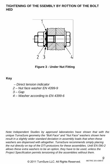
TIGHTENING OF THE ASSEMBLY BY ROTATION OF THE NUT
Key
1 – Direct tension indicator2 – Nut face washer EN 14399-93 – Gap4 – Washer according to EN 14399-6
(not required for grade 8.8)
8METRIC EN 14399-9
Figure 2 - Under Nut Fitting
Note: Independent Studies by approved laboratories have shown that with theunique TurnaSure geometry the “Bolt Face” and “Nut Face” washers shown hereresult in a slightly wider standard deviation in assembly loads that when thesewashers are dispensed with altogether. TurnaSure recommends simply placingthe nut directly on top of the DTI protusions for these assemblies. Until EN 1090-2allows these extra washers to be an option, they have to be used, unless theProject Specification permits tensioning of the assemblies without them.
© 2011 TurnaSure LLC. All Rights Reserved.
9METRIC EN 14399-9
TIGHTENING OF THE ASSEMBLY BY ROTATION OF THE BOLTHEAD
Key
1 – Direct tension indicator2 – Nut face washer EN 14399-93 – Gap4 – Washer according to EN 14399-6
Figure 3 - Under Nut Fitting
Note: Independent Studies by approved laboratories have shown that with theunique TurnaSure geometry the “Bolt Face” and “Nut Face” washers shown hereresult in a slightly wider standard deviation in assembly loads that when thesewashers are dispensed with altogether. TurnaSure recommends simply placingthe nut directly on top of the DTI protusions for these assemblies. Until EN 1090-2allows these extra washers to be an option, they have to be used, unless theProject Specification permits tensioning of the assemblies without them.
© 2011 TurnaSure LLC. All Rights Reserved.

TIGHTENING OF THE ASSEMBLY BY ROTATION OF THE BOLTHEAD
Key
1 – Direct tension indicator2 – Bolt face washer EN 14399-93 – Gap 4 – Washer according to EN 14339-5 or EN 14399-6
(not required for grade 8.8)
10METRIC EN 14399-9
Figure 4 - Under Bolt Head Fitting
Note: Independent Studies by approved laboratories have shown that with theunique TurnaSure geometry the “Bolt Face” and “Nut Face” washers shown hereresult in a slightly wider standard deviation in assembly loads that when thesewashers are dispensed with altogether. TurnaSure recommends simply placingthe nut directly on top of the DTI protusions for these assemblies. Until EN 1090-2allows these extra washers to be an option, they have to be used, unless theProject Specification permits tensioning of the assemblies without them.
© 2011 TurnaSure LLC. All Rights Reserved.
11METRIC EN 14399-9
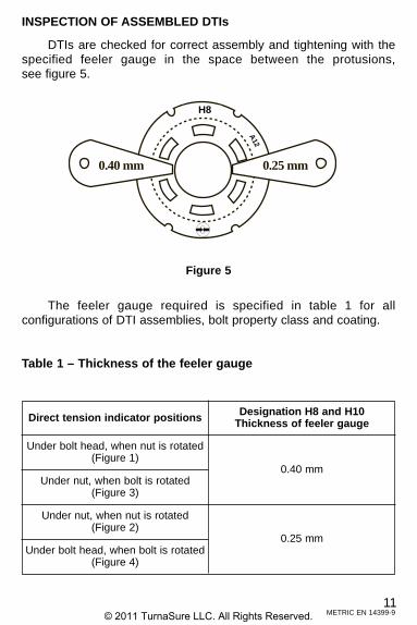
INSPECTION OF ASSEMBLED DTIs
DTIs are checked for correct assembly and tightening with thespecified feeler gauge in the space between the protusions, see figure 5.
The feeler gauge required is specified in table 1 for all configurations of DTI assemblies, bolt property class and coating.
Table 1 – Thickness of the feeler gauge
Direct tension indicator positions Designation H8 and H10Thickness of feeler gauge
0.40 mm
Under bolt head, when nut is rotated(Figure 1)
Under nut, when bolt is rotated(Figure 3)
Under nut, when nut is rotated(Figure 2)
Under bolt head, when bolt is rotated(Figure 4)
0.25 mm
Figure 5
M-22 8.8
H120.40 mm 0.25 mm
H8
A12
© 2011 TurnaSure LLC. All Rights Reserved.

Due to varitions in steelwork components it is unusual for DTIassemblies to flatten the protusions of the DTI evenly, see figure 6.
Key
1. ‘No go’ gap if refusal occurs.2. ‘Go’ gap if refusal does not occur.
To standardise the method of checking that the assembly is correctly tightened EN 1090-2 Annex J specifies the number of gapsfor each type of DTI that the feeler gauge must not enter, see table 2.
Table 2 – Feeler gauge refusals
12METRIC EN 14399-9
Number of direct tensionindicator protusions
Minimum number of feeler gauge refusals
Figure 4 - Under Bolt Head Fitting
4
5
6
7
8
9
3
3
4
4
5
5
© 2011 TurnaSure LLC. All Rights Reserved.

13
Annex J of EN 1090-2 includes a requirement that no more than10% of the direct tension indicators in a connection bolt group shallexhibit full compression of the indicators. This is due to be consideredfor change at the next revision of EN 1090-2.
Within the United Kingdom the following clause has been included in the National Structural Steelwork Specification forBuilding Construction – 5th Edition – CE Marking Version.
6.3.3 INSPECTION DURING AND AFTER TIGHTENINGUnless otherwise stated in the Project Specification, inspection
shall comply with the requirements specified in BS EN 1090-2 forExecution Class 2. Unless prohibited by the Project Specification, thetightening of direct tension indicators to apparent full compression inmore than 10% of cases shall not be a cause for rejection providedthat the manufacturer’s certificate of conformity confirms that isacceptable in terms of the specified suitability tests.
For TurnaSure® direct tension indicators the report from RowanUniversity in the USA on “Load – rotation tests of M24 x 90 HR 10.9Galvanized Structural Bolt Assemblies with DTIs”, dated 29thOctober 2010 is considered to meet this requirement; copies of thereport are available from TurnaSure LLC.
ON SITE TESTINGIf required by the Project Specification on site testing of
DTI assemblies shall be carried out in accordance with Annex H ofEN 1090-2. Eight sample assemblies are to be taken for each boltdiameter, fitted in a load cell and tightened to the specified gap.
The DTI assemblies shall meet the preload (Fp,C) values asspecified in the following – Fp,C # Fb,I # 1.2Fp,C and table 3.
Table 3 – Preload Values in kN
Property ClassBolt diameter in mm
8.8
10.9
12 16 20 22 24 27 30 36
47 88 137 170 198 257 314 458
59 110 172 212 247 321 393 572
METRIC EN 14399-9© 2011 TurnaSure LLC. All Rights Reserved.

14METRIC EN 14399-9
LUBRICATION
Lubrication is one of most critical features of a preloaded boltingassembly; DTI assemblies require sufficient lubrication to achieve theminimum preload and the further rotation of Du2. Other systems suchas ‘torque control’ need significantly more control; EN 1090-2 and EN14399-2 specify by means of a K- class the requirements for eachtightening method.
K0 – no specific requirements except to achieve preload andDu2.
KI – individual values of the k-factor shall be in the range 0.10 # ki # 0.16.
K2 – mean values of the k-factor shall be in the range 0.10 # km# 0.23 and the coefficient of variation Vk # 0.10.
The k-factor is determined as part of the suitability for preload-ing test in EN 14399-2.
The following table details the K-class required for each tighteningmethod.
Tightening Method K-class Required
DTI Method K0Can use K1 or K2
Highways Agency Part-turn Method K0Can use K1 or K2
Combined Method K1
Torque Control Method K2
HRC (TC bolt) Method K0 with HRD nutotherwise K2
© 2011 TurnaSure LLC. All Rights Reserved.

®
Tu
rnaS
ure L
LC
InternationalH
eadquartersP
hone: 215-750-130 0F
ax: 215-750-6300340 E
. Maple A
venu e, Suite 206
Website: w
ww
.turna sure.comLanghorne, P
A 1904 7
© 2011 TurnaSure LLC. All Rights Reserved.
For more information visit:https://www.andrewsfasteners.uk