Web-Based CPC / CPA / PSA Marketing Vendors · We welcome you to the ranks of Log Home owners. Your...
27
Richard Spoor President – eLogHomes.Com Dear Log Home Enthusiast, On behalf of myself and everyone at eLogHomes.Com, I’d like to thank you for your time and your interest in our log home packages and our website. I sincerely hope that our free log home building guide will be an aid to you and help you to move forward with building the log home of your dreams. At eLogHomes we streamline the process and keep operating costs low to provide our customers with the highest quality and most competitively priced log home packages in the industry. As a log home manufacturer and business owner who believes in providing personalized service to all of our customers, and with 35 years of industry experience and know how, I’d like to make myself available to you to answer any questions that you may have along the way, so please feel free to email me directly at [email protected] if I can be of any assistance. Sincerely, Richard Spoor Richard Spoor President eLogHomes.Com
Transcript of Web-Based CPC / CPA / PSA Marketing Vendors · We welcome you to the ranks of Log Home owners. Your...

Richard Spoor President – eLogHomes.Com Dear Log Home Enthusiast, On behalf of myself and everyone at eLogHomes.Com, I’d like to thank you for your time and your interest in our log home packages and our website. I sincerely hope that our free log home building guide will be an aid to you and help you to move forward with building the log home of your dreams. At eLogHomes we streamline the process and keep operating costs low to provide our customers with the highest quality and most competitively priced log home packages in the industry. As a log home manufacturer and business owner who believes in providing personalized service to all of our customers, and with 35 years of industry experience and know how, I’d like to make myself available to you to answer any questions that you may have along the way, so please feel free to email me directly at [email protected] if I can be of any assistance. Sincerely, Richard Spoor Richard Spoor President eLogHomes.Com

HHOOWW TTOO BBUUIILLDD HAA L
HLOOGG HHOOMMEE
OOWW TTOO BBUUIILLDD AA LLOOGG HHOOMMEE

Introduction We welcome you to the ranks of Log Home owners. Your new home will afford a level of economy, layout flexibility, and genuine warmth and charm seldom found in any other type of home. Whether you build the entire home yourself, or have it partially or totally constructed for you, we believe you will be pleased with the authenticity of appearance and economy of construction. Add to this the satisfaction of choosing, planning, and building your own home. When your home package is delivered, it is important that you check that the materials on the truck are in good condition and that all necessary items have been received. Please be sure to have off-loading equipment (such as a forklift with a 6000 pound lift capacity) on hand to help you unload these materials. This manual should be used as a reference guide to help you understand the construction techniques involved in building your log home. The standard details along, with this construction manual and your final construction prints will also instruct you in these techniques. Questions about any aspect of your home not answered in this manual should be directed to your Customer Service Representative.
We suggest that you thoroughly familiarize yourself with the contents of this manual before beginning construction on your new log home. The step-by-step assembly instructions are non-technical and easy to follow. The guide also contains drawings and technical notes. The words, pictures, and drawings provide a clear description of the construction process. The Standard Detail Sheet supplied with the blueprints for you home is your reference for specific measurements necessary for building with your chosen log style. The Intended Use of Materials List furnished on delivery will help you identify the various components and the amounts supplied for each step in the building of you weather tight home shell. Please pay special attention to the outside wall bracing procedure. This step is strongly recommended. A list of necessary tools is included in this manual. To avoid delays, be sure to have all these items on hand before beginning construction. Review the glossary of terms for specific definitions. And thank you for choosing a home from eLog Homes.
1

Choosing a Building Site
There are many considerations in choosing a building site. Most people make their decision based on personal taste and selling price. We suggest that you also consider zoning, easements percolation test, etc. as you make your decision. 1. True cost of the land. The selling price can be very deceptive; the true cost of your land includes all the work that must be done before you are ready to build on it. The cost of bringing water, septic, and electrical power should be considered as well as site preparation. Large trees, boulders or ledge rock can quickly raise the cost of site preparation beyond your budget. Check with local well drillers and excavators about typical costs in the area of you lot. 2. Choose a site that fits the architectural style of the home you want to build. Our design flexibility allows you to customize your home to suit your building site.
3. Energy efficiency can save you many dollars over the years. First determine whether your major expense will be heating or air con-ditioning. Remember, deciduous trees (those that lose their leaves in winter) close to your home will shade your home during warm summer months while allowing winter sun to warm your home. Evergreens to the north and west will help to break prevailing winter winds to give you more comfort in the winter.
4. Be careful about low spots, especially on the side of a hill. Once the normal ground cover is removed, flooding and erosion could become a problem. 5. Generally be cautious of the “Great Bargain” as spending only a small percentage more can save you many thousands of dollars and a lot of aggravation.
2

Preparations for Building Your Log Home Foundations The foundation should be completed before the delivery of your log home package. Since this is a critical part of your home’s construction, we suggest that you have a masonry contractor build your foundation. The Construction Guide contains information about foundations and floor systems that may be used in your log home. The decision about the type of foundation you want must take into account whether you want a basement, crawl space, pier, or slab foundation. There are advantages to each type that should be considered, and these may depend on the area in which you live. Your masonry contractor will advise you on the specifications for your foundation needed to meet building code in your area.
3

Types of Foundations Slab Foundation A concrete slab poured over compacted fill, which is covered with a layer of gravel or crushed stone. Immediately beneath the slab is a vapor barrier, usually made of polyethylene sheeting. The slab is supported by footings which may be poured separately or along with the slab.
Crawl Space Foundation This type of foundation consists of a perimeter concrete block or poured concrete wall approximately 32”- 40” in height on a poured concrete footing. The resultant space provided between the grade is typically 2’-3’. Crawls space foundations are normally used in areas where a high water table prohibits the use of a full basement. In addition, because a crawl space foundation requires less material (concrete block/poured concrete) than a full basement foundation, they may be used when cost savings are an issue.
Basements Basement foundations are normally used in areas where the slope of the grade and the depth of the water table allow them. A full basement has concrete blocks or poured concrete walls built on separately poured concrete footings. It also has a poured concrete slab floor. An expansion joint ½ inch thick between the basement walls and the poured slab floor will diminish cracking due to expansion and contraction caused by temperature changes.
Pier Foundation The pier type foundation is typically used in costal areas where high water and the potential for flooding are prevalent. Piers are typically made of either pressure treated posts or concrete piers, and include a beam that is constructed at the circumference of the home.
Anchor Bolts are embedded at prescribed depths in concrete every 4 feet along the foundation perimeter. These bolts are used to anchor the sill plate to the foundation.
A Narrow Air Space must be left around the wood girder where it rests on the foundation to prevent rot. A metal or asphalt buffer is inserted beneath the girder.
Footings support foundation walls or piers. The specifications for footings are governed by the weight of the load they will bear, the type of concrete used and the soil bearing capacity.
4

Off-Loading Your Log Home Package Unloading your log home package involves heavy lifting. You will need 3-4 able-bodied helpers. It should take you no more than two hours per truckload to accomplish off loading. To speed this process, we highly recommend that you rent an all terrain forklift capable of lifting at least 6,000 pounds 13 feet off the ground. The Materials Packing List and Lumber Pull Sheet supplied will help you in checking each item as it is unloaded. You may wish to appoint one person to check the items as they are unloaded. Make note of any shortages or damage on the Completed Delivery Checklist at that time, so that materials may be replaced. The truck driver will return this signed check list to us. All shortage and damages to materials must be noted on that statement. •It is important to carefully stack materials on dunnage boards to keep them off the ground. Cover the plywood with the plastic sheeting furnished with your package. Keeping your building components clean and dry is important to the final appearance of your home. Stack each type of building component together and as close to the foundation as possible. This way, items will be easily accessible as needed. •Windows, doors and skylights should be unloaded carefully by hand.
•Banded units of lumber and log materials should not be un-banded until just prior to them being used for construction. •Windows, doors, skylights, nails and log wall accessories (caulking, foam gasket, dowels, lag screws) should be stored inside a secure location. •Lumber, plywood, logs and log siding should be stored with bands in place, remain under cover and not in direct contact with the ground. •Sheets of plywood used to separate windows and doors during shipment are part of the log home package materials. If your log home package includes roof trusses, it is very important that you keep these trusses stacked in the position which they were loaded on the truck. They were loaded this way to assure a perfectly aligned roof. Be sure not to reverse any trusses during unloading or building. You may wish to mark the trusses with a can of spray paint before unloading. REMEMBER: If your unloading process takes longer than the allotted time of 2 hours per truck you will be charged for the overtime.
5

TOOLS It is recommended that you make arrangements to have electrical power on your building site. Your utility company will normally provide you with temporary service that will be metered to you. If electrical power is not available, we suggest that you rent a portable gasoline generator capable of producing at least 4-5 KW of power. Assembling the necessary tools for building your log home will save valuable time. You will need: • ½ “ impact wrench • ½ “ electric drill • ½ “ x 12” drill bit fitted with an 1” counter
sink bit • 1-1/8” auger bit • 20 ounce claw hammer • 4 foot level • 100 foot tape measure • 16 “ circular saw • Cross cut hand saw or 7” circular saw • Caulking gun • Chalk line • Carpenter’s framing square • 1-1/2” wood chisel • Two sets of saw horses • Carpenter’s pencils • Adjustable T-square • Your blueprints or plans • Standard detail sheet for your log style • Intended use sheet Materials you will need to provide: • Four (4) 4 x 4 x 10’ corner posts (or one for
each corner)- Two 2 x 4‘s may be nailed together to form each corner post.
• Twenty (20) 2 x 4 x 8’ for bracing corner posts, window and door bucks
• Twelve (12) 2 x 4 x 12’ to be used for outside wall bracing to prevent walls from bowing
• 2 x 4 material for truss bracing as required
6

FLOOR SYSTEM Sill Sealer For homes to be built on full basements or slab foundations, sill sealer material is supplied to help limit air infiltration (this material is not for homes on crawl space or pier foundations). The detail of the sill plate installation shows the proper location for the sill sealer material (between the top of the foundation wall and the treated sill plate) and also references a termite shield. Though the termite shield is not supplied, its use is recommended for those parts of the country that require such.
Installing the Sill Plates Sill plates are of 2x6 pressure treated material. The sill plate is to be set into place before girders and beams. Remove the washers and nuts from the anchor bolts imbedded in the top of the foundation and lay the pressure treated sill plate along the foundation wall. Draw a line across the sill plate on each side of each of the bolts. Measure the distance from the center of the bolt to the outside edge of the foundation. Use this distance to locate the position of the bolt holes from the edge of the sill. You will need to make separate measurements for each anchor bolt.
After all the anchor hole are located, place the sill on saw horses and bore the holes. Most carpenters prefer to bore the holes ¼ inch larger than the diameter of the bolt to allow for slight inaccuracies in the layout and to permit adjustments in the sill when it is anchored in place. As each section is laid out and holes bored, place it in position over the bolts. As nuts are tightened on bolts (be sure to include washers), see to it that the sill plates are properly aligned and are flush to the outside edge of the foundation wall. The sill plate must be level and straight. Low spots in the foundation can be shimmed with wooden wedges; however, it is better to use grout and mortar.
Crowning of Lumber Floor joists and girder material should always be installed with the crown up to allow for even movement of these members when a load is placed on them. This procedure is also applicable to roof rafters.
Girders and Beams The floor joists for the first floor system rest on the sill plate on top of the foundation walls. Usually the distance between the foundation walls (called the span) is too wide for the floor joist to make the full span so additional support must be provided. Girders (also called beams), resting on the foundation walls and on pier/columns provide this additional support. The girders may consist of solid timbers, built up members, or steel beams. Sometimes a load bearing partition can replace a girder or beam. Steel beams are not furnished with the material package.
7

Built up girders in the basement are usually made of three pieces of lumber nailed together. When used to support the second floor they may be 2, 3 or 4 laminate. Joints on the girders should be only over support locations. The materials for your girder(s) are included in your package and have been designed to meet load requirements for your particular plans.
First floor wooden girders are set so the top is level with the top of the sill plate.
Floor Joists Floor Joists are the framing members that support the weight from the various areas of the floor to the sills and girders. The floor joists will rest on top of the sill plate and on top of the girder or bearing wall. In some situations, such as a second floor system, where an unbroken ceiling line is preferred, the floor joists may be attached to the side of the girder with joist hangers. This is called a flush girder. In this situation the top of the floor joists are flush with the top of the girder. Study the blueprints carefully and note the size, spacing, and direction of run for the joists. Become familiar with the various dimensions that show the locations of posts, columns, supporting partitions and girders. The position of the joints can be laid out directly on the rim joist as illustrated. The position of an intersecting framing member may be laid out by making a single line and the placing an “X” to indicate the side of the joist is installed.
Joists are doubled where extra loads must be supported. When a partition wall runs parallel to the joists, a double joist is placed underneath. Joists which are below partitions carrying plumbing or heating pipes are usually spaced apart. Joists must be doubled around openings in the floor frame for stairways, chimneys, and fireplaces. Become thoroughly familiar with the blueprints at each floor level so that adequate support can be provided.
Openings Place sheets of plywood across the joists to form a temporary working deck to install header and tail joists. First set the trimmer joists in place. Some times a regular joist will be located in such a position that it can serve as the first trimmer. The drawings show the steps of assembly. Metal joist hangers are used to assemble headers, trimmers and tail joists. Cut the required number of headers and tail joists to length. Make sure the cuts are square and true. Considerable strength will be lost in the finished assembly if the members do not fit tightly together. Lay out the position of the tails on the headers by transferring the marks made on the main header in the initial layout. When the assembly, of the tail joists and first headers is small, they are sometimes nailed together and then set into place. Usually, however the headers are installed and then the tail joists can be temporarily nailed to each
8

trimmer to accurately locate the header and hold it while it is nailed. After the first header and tails joists are in position between the first trimmers, the second or double header is nailed into place. Be sure to nail through the first trimmers into the second header using three 16d nails at each end. Finally the second trimmer is placed and nailed to the first trimmer.
.
Bridging Once the floor joists are all in place bridging is installed. Metal bridging is furnished with the material package. The purpose of bridging is to tie the floor joists together to prevent the floor joist from twisting, and to enhance the structural integrity of the floor system. General standards suggest that bridging should be installed at intervals not to exceed eight feet on center. To install bridging, begin by snapping a chalk line on the top of the floor joist. This line will run perpendicular to the floor joist and should be spaced at the prescribed interval. The bridging will be located on each side of this line in alternating positions. Only attach the bridging in the top location at this time. The bottom will be attached from below once the floor is completed Solid bridging is also known as blocking and used in lieu of cross bridging and may be used in some situations
9

Subfloors The lying of the subfloor is the final step in completing the floor frame. The main purpose of the subfloor is to add rigidity to the structure and provide a base for the application of the finished flooring materials. It also provides a surface upon which the carpenter can layout and construct additional framing. Your package includes ¾ inch locking plywood or O.S.B. For both the first and second floor system, a ¼” bead of construction adhesive (included with the package) is to be placed on top of the floor joists before the plywood sub-floor is laid. The long dimension of the sheet of plywood should run perpendicular to the joists. The plywood should be laid so joints alternate. 8d sinker type nails are used to attach the plywood to the joists. Nails should be spaced 6 inches apart along the edges and 10 inches along the intermediate members. Check local building code for compliance of this nailing schedule.
Starter Plate When building on a wood floor system, your starter plate will be a 2x4 spruce for standard 6” log walls and a 2x6 spruce for a 8” log wall. The starter plate is to be fastened to the floor framing with 16d sinker nails so that the plate is flush to the outside edge of the floor system (as depicted in diagram). Transfer markings from any door openings to the starter plate and remove the section of starter plate within the opening. When building on a slab foundation you will be supplied with (2) starter plates. For 6” log wall you will be provided with 2x6 P.T. plate that will
10

need to be ripped down to 4 ½”. Another 2x4 spruce plate that will applied on top. For a 8” log wall you will be provided with a 2x8 P.T. plate that will need to be ripped down to 6 ½”. Another 2x6 spruce plate that will be applied on top. Mark all anchor bolts embedded in slab to you P.T. plate. Drill out holes so that your P.T. plate is mounted flush to the outside edge of your slab foundation with sill sealer applied at contact area of your plate to slab. Next is to apply your spruce starter plate on top of your P.T. plate so that the edge is also aligned with the outside edge of the slab foundation. Fasten spruce plate to P.T. plate with 16d nails (as depicted in diagram). Transfer markings from any door openings to the starter plates and remove the sections of starter plates within the opening.
Marking Your Floor Plan Prior to laying out the first course of logs, it is recommended that you lay out your floor plan on the deck or foundation. Using the blueprints, carefully mark the deck with a carpenter’s pencil and chalk line for the following: •Location of windows and doors and the size of each •Interior partitions and openings. Knowing where partitions and closets are located will allow you to place butt joints behind partitions and inside closets where they will not be visible. •Electrical outlets.
11

Door and Window Bucks You may now begin building the door and window rough frames, called bucks, from 2 x 4 lumber for 6” logs and 2 x 6 lumber for 8” logs, supplied with the package. Although you are furnished with a rough opening schedule for the doors and windows, it is recommended that you measure each door and window and build the bucks individually. Before you measure the height required for each window, remove the portion of the window side jamb that extends below the sill. Make sure that you retain the square cut so that the window frame will have a level support and so that all of the weight of the window will not rest solely on the front edge of the sill. Removing this extension provides for a better fit between the window sill and the log wall. Failure to remove this extension will result in a gap between the front of the sill and the log wall. You may wish to number your door and windows and their corresponding buck frames to be sure that the proper frame is used. (You may delay construction of the window bucks until you reach the course of log on which the window will rest.) When constructing buck frames, make sure that the measurement is for the outside measurement of the door or window frame. The horizontal pieces of the buck frame should be nailed between the vertical pieces as they will be removed prior to window and door instillation. The interior of width of the buck frame will be the outside width of the door or window frame plus an additional ½” for clearance. The height will be the height of the door or window frame plus 1” on top to accommodate log settling.
12
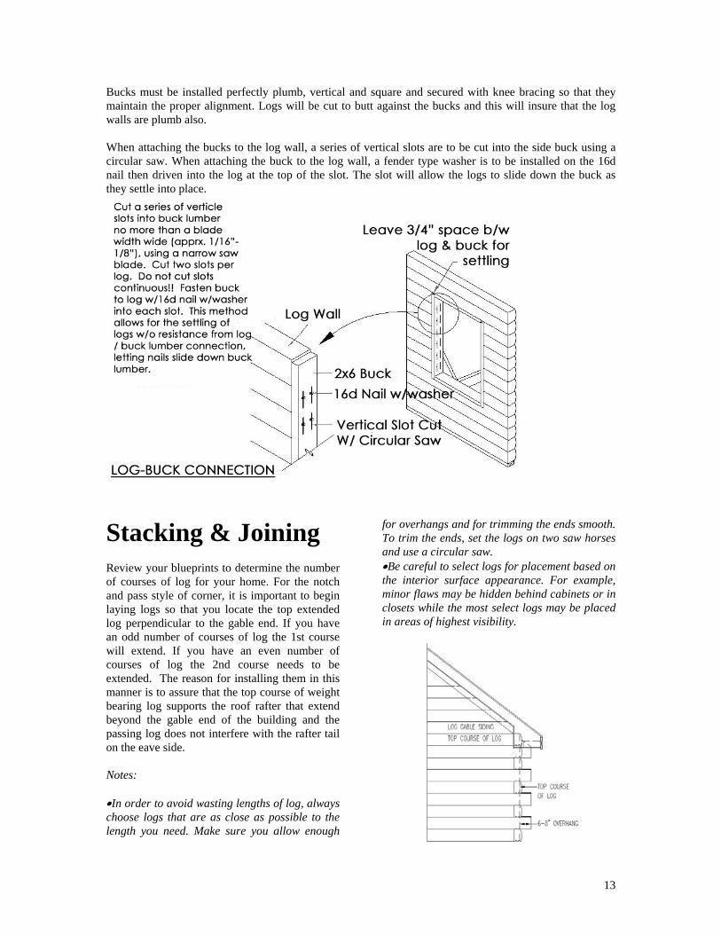
Bucks must be installed perfectly plumb, vertical and square and secured with knee bracing so that they maintain the proper alignment. Logs will be cut to butt against the bucks and this will insure that the log walls are plumb also. When attaching the bucks to the log wall, a series of vertical slots are to be cut into the side buck using a circular saw. When attaching the buck to the log wall, a fender type washer is to be installed on the 16d nail then driven into the log at the top of the slot. The slot will allow the logs to slide down the buck as they settle into place.
Stacking & Joining
13
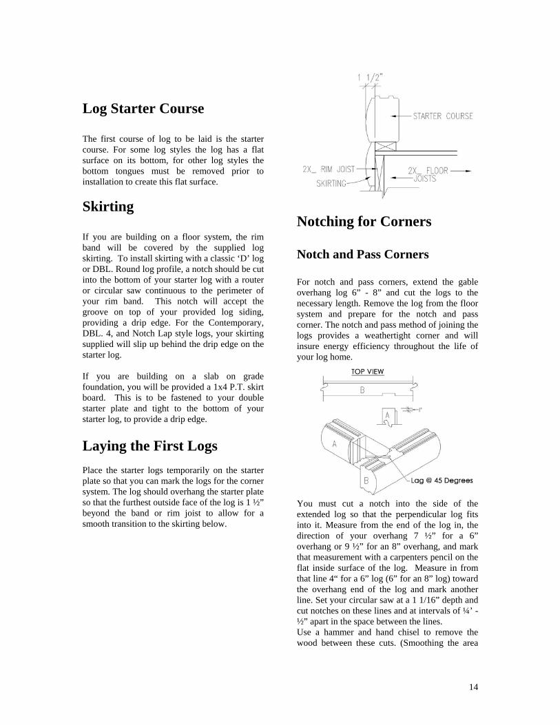
Review your blueprints to determine the number of courses of log for your home. For the notch and pass style of corner, it is important to begin laying logs so that you locate the top extended log perpendicular to the gable end. If you have an odd number of courses of log the 1st course will extend. If you have an even number of courses of log the 2nd course needs to be extended. The reason for installing them in this manner is to assure that the top course of weight bearing log supports the roof rafter that extend beyond the gable end of the building and the passing log does not interfere with the rafter tail on the eave side. Notes: •In order to avoid wasting lengths of log, always choose logs that are as close as possible to the length you need. Make sure you allow enough
for overhangs and for trimming the ends smooth. To trim the ends, set the logs on two saw horses and use a circular saw. •Be careful to select logs for placement based on the interior surface appearance. For example, minor flaws may be hidden behind cabinets or in closets while the most select logs may be placed in areas of highest visibility.
Log Starter Course The first course of log to be laid is the starter course. For some log styles the log has a flat surface on its bottom, for other log styles the bottom tongues must be removed prior to installation to create this flat surface.
Skirting If you are building on a floor system, the rim band will be covered by the supplied log skirting. To install skirting with a classic ‘D’ log or DBL. Round log profile, a notch should be cut into the bottom of your starter log with a router or circular saw continuous to the perimeter of your rim band. This notch will accept the groove on top of your provided log siding, providing a drip edge. For the Contemporary, DBL. 4, and Notch Lap style logs, your skirting supplied will slip up behind the drip edge on the starter log. If you are building on a slab on grade foundation, you will be provided a 1x4 P.T. skirt board. This is to be fastened to your double starter plate and tight to the bottom of your starter log, to provide a drip edge.
Laying the First Logs Place the starter logs temporarily on the starter plate so that you can mark the logs for the corner system. The log should overhang the starter plate so that the furthest outside face of the log is 1 ½” beyond the band or rim joist to allow for a smooth transition to the skirting below.
Notching for Corners Notch and Pass Corners For notch and pass corners, extend the gable overhang log 6” - 8” and cut the logs to the necessary length. Remove the log from the floor system and prepare for the notch and pass corner. The notch and pass method of joining the logs provides a weathertight corner and will insure energy efficiency throughout the life of your log home.
You must cut a notch into the side of the extended log so that the perpendicular log fits into it. Measure from the end of the log in, the direction of your overhang 7 ½” for a 6” overhang or 9 ½” for an 8” overhang, and mark that measurement with a carpenters pencil on the flat inside surface of the log. Measure in from that line 4“ for a 6” log (6” for an 8” log) toward the overhang end of the log and mark another line. Set your circular saw at a 1 1/16” depth and cut notches on these lines and at intervals of ¼’ - ½” apart in the space between the lines. Use a hammer and hand chisel to remove the wood between these cuts. (Smoothing the area
14

with a hand block plane or chisel will insure that the abutting log will fit flat against the notch). Using a flexible straight edge, mark the curved surface of the log to be inserted, 1” from the end. Set your circular saw at a 1 ½” depth and make a cut along that line. Next, measure 3 15/16” for a 6” log (5 15/16” for an 8” log) from the flat face of the log and make a vertical mark. Leaving your saw at a 1” depth, go to the end of the log and remove the curved portion of the log. This gives you a square off end to insert into the notch prepared in the passing log. Using a hand chisel, the tongues now need to be removed from the extended log for an area slightly wider than the notch on the notched log and approximately 1” back on the log to be inserted, so that the next course of logs will properly track over the corner. Each corner needs to be prepared for the notch and pass corner system before it is set into place. Contemporary Corners The contemporary type corner is typically used with the contemporary, double 4 and notch lap style logs. This type of corner does not have a log that extends beyond the building line but rather has vertical corner boards to finish off the outside of the corner. For the male log measure 4” for the 6” log, (6” for the 8” log) from the inside face of the log toward the outside face. Mark a vertical line. Next measure 1” from the end of the log and mark a vertical line across the face of the log. With your circular saw set at a 1” depth cut along the 2 vertical lines to remove a portion of the face of the log leaving a rectangle 4” wide for the 6” log, and 6” for the 8” log by the height of the log protruding 1” beyond the face of the log. For the female log measure 4” from the end of the log along the inside face and draw a vertical line. Next measure 1 ½ “from the inside face across the end of the log. And draw a vertical line. Next continue toward the face of the log across the end and measure 2 ½” beyond the precious mark and draw another vertical line. Finally measure 3 ½” along the outside face of
the log and draw a vertical line. You have now completed all of the marking. Next set your circular saw at a 1 ½” depth and make a series of cuts ½” to 1/.4” apart along the inside face of the log from the mark 4” in toward the end. After these cuts have been made you may remove the material with a hammer and chisel. Next leaving your circular saw at the 1 ½” depth make a vertical cut along the line you marked across the outside face of the log. Finally set your circular saw at a 3 ½” depth and make a vertical cut on the end to remove the outside face portion of the log. This will leave a rectangular protrusion that is 2 ½” wide. When these to logs are interlocked the outside face will allow for a 1 ½” x 3 ½” vertical corner board on one side of the corner and a ½” x 5” corner board on the other side, giving a reveal of 5” in each direction. Saddle Notch, Dovetail, Double Round Log Notch & Pass Corners. The saddle notch, dovetail and double round log notch and pass corners are corners that are also used on Log Home Liquidations log homes. However each of these corners requires specialty equipment and tools to cut. Although not impossible to cut on site, they are very difficult and time consuming. We recommend that should you choose one of these type of corners you have the logs for you home pre-cut at our manufacturing facility.
Setting the First Course Logs should be set in place by two people, being careful to prevent damage to the tongues of the logs and injury to fingers. After you have measured, marked and cut the logs you are ready to set them in place. If you are using a contemporary, double 4 or notch lap style of log you must now remove the tongues from the bottom of the log. (This applies to the first course only) First dry set all of the perimeter logs in place to make sure that they fit properly.
15

Once this fit has been established, remove the logs from the starter plate. Next, place a 1/8” bead of caulking on the starter plate before setting the log on it. Set the log on a saw horse and using a ½” drill bit with a 1” countersink, pre-drill for the lags, between the two tongues, (between the two grooves for contemporary, double 4 and notch lap style logs) completely through the log with the counter sink going at least 1” below the surface of the log, 6” in from the end and every 30” along the length of the log. These pilot holes must be perpendicular to the top surface of the log and all saw dust and debris must be cleaned out of the hole prior to the lag screws being inserted, to allow the logs to properly settle into place. Set the log in place with the outside edge 1 ½” beyond the floor system so as to line up properly with the skirting. Using an impact wrench, install the lags or log screws with washer, making sure that the head of the lag or log screw is recessed at least 1” below the surface of the log. This will insure that the heads of the lags or log screws will not prevent the logs from properly settling into place.
Joining the Logs Care should be taken to insure that all vertical butt joints are constructed so as to achieve wood-to- wood contact at all points. Dowels are to be inserted at all corner and butt joints only after logs are tightly butted together and tightly secured (lags or log screws in place). To install the dowel; drill a 1 1/8” diameter hole through the log and into the log or starter plate below so that the top of the dowel is ½” below the log surface, place a small amount of caulking into the drilled hole and gently tap the dowel into place. Apply caulking as necessary to fill the space up to the log surface.
Inside Corners If your home is L-shaped, or has an inside corner review the details for this application and the necessary cuts for your log style on the Standard Detail Sheets.
Stacking the Logs Measure and cut the logs for subsequent courses, alternating the cuts for each course for the notch and pass corner. For the notch and pass corner application the tongues must be removed where one log passes over the other. Place the passing log on top of the log below and mark where the tongue must be removed. Remove the tongue in this area with a chisel. Just prior to laying each log after the first course, apply the polyfoam gasket material. Polyfoam gasket is to be applied adhesive side down, in the center of each tongue (or in the bottom groove for contemporary, double 4 and notch lap log styles). Where joints in the polyfoam gasket are necessary, each strip is to be lapped over the other to prevent any separation from occurring. DO NOT STRETCH THE POLYFOAM! The paper separator is to be removed once the polyfoam is in place. The final step before setting the log in place is to apply a 1/8” bead of caulking along the base of the outside tongue (or groove in the case of the contemporary, double 4 or notch lap styles). Take care not to use too much caulking, or it may seep out and discolor the logs. •Be sure to remove all sawdust and debris from the joining log surfaces to assure the tightest possible joint. •It is best that pre-drilling for the lags is done on a sawhorse rather than set in place. This will
16

prevent you from drilling into the log below and place the log at a workable height to assure the holes are drilled plumb. If applying log screws you can apply them with the log in place. •Lightly mark the locations of the lags or log screws on the inside of the logs in pencil. This will prevent drilling into a lags or log screws when you drill for electrical outlets or for dowels.
Electrical Outlets After the second course of log is lagged or screwed into place, it is time to mark the location of the electrical outlets. Outlets are typically located in the second course of log. When the locations are marked, measure to a point at the center of each outlet location and drill down through the completed courses of log and starter plate using a 1 1/8” auger bit. This hole will accommodate the wiring to the box. A recess must be cut into the log at the appropriate height to allow the outlet box to be set in. Trace the outline of the box on the inside face of the log. With a circular saw or reciprocal type saw make two vertical cuts then remove the block using a chisel. Check with your local building officials for the required height to install the outlets.
Windows/ Doors Check the floor plan to assure that you properly marked the location of window and door openings on the deck or concrete slab. The tops of most standard windows should be level with the tops of the doors. You may have to notch into the courses of log above/below window openings. It will be easier to cut out the notches if you measure and cut them before the log is lagged into place. If you must notch down into the log below the window, carefully measure and mark for accurate cutting. As an aid in the alignment of the buck frame, set them flush with inside or outside portion of the logs. Brace and plumb the buck frames either to the floor or the ground outside. Now the logs between the window buck frames and to the corners can be installed. Remember to nail the buck to the ends of the logs through the slots previously cut into the sides of the buck frame. There must be a gap above each window and door buck to provide for proper settling. You may have to notch into the log above to accomplish this. The gap must be at least 1”.
Wall Bracing It is important to brace you log walls so that they do not bow as you stack the logs. Put a piece of lumber on the inside of the window and door bucks and nail it there. Then check the buck to
17

be sure it is plumb. Check this with a 4’ level. When the buck is plumb, nail a small piece of lumber to the deck where the end of the bracing rests. Nail the bracing lumber to this smaller piece. This should be done for all of the walls of the home. Once you have completed the top course of log you can begin to build either your second floor system, as per the description provide for the first floor system, or begin to build the roof. Consult you blueprints. In either situation, to complete the log portion, the tongues on the top course of log should be removed with a hand chisel, for the classic and double round style of log.
Interior Walls The interior walls of the first floor can now be installed per the layout on the floor deck and as depicted on your blueprints. All of the walls are to have a single bottom plate and a double top plate. Most walls will be of 2 x 4 construction with the studs at 16” o.c. Some walls however may be constructed with 2 x 6 studs such as plumbing walls. The openings in the walls for door and cased openings will have a header above them. Review the blueprint to determine the size of these headers. Any interior partitions which contacts the log wall are to be attached with a slip joint, by cutting a series of vertical slots in them, to allow for proper settling of the logs. The top of the partition walls are to be located at ½” below the top of the log wall. See Detail.
Erecting the Roof
Erecting the roof, whether it is conventionally framed or pre-manufactured roof trusses, is a critical part of the construction of your new home. A poorly built roof will detract from the appearance and the value of your home. You may want to hire a professional carpenter to assist you. Be sure to have at least five people on hand. If your roof system is to be constructed from large trusses, you may wish to rent a small crane for the day. Roof framing provides a base to which the roofing materials will be attached. It must be strong and rigid. The roof can contribute a distinctive and decorative feature to the structure. The blueprints for your home package have been designed to provide you with the proper spacing and pitch of your roof framing.
Conventional Roof System Ceiling Framing A ceiling frame is the assembly just below the roof that carries the ceiling surface. On homes with two levels, the ceiling of the lower level is carried by the floor joists. The basic construction is similar to floor framing. The main difference being, the members are lighter and the rim joists are not used around the outside for a ceiling only system. The main framing members are called joists, and like floor joists, their size is determined by the length of the span and the spacing used. Consult
18

your Intended Use of Materials List and blueprints for your home. Ceiling joists usually run across the narrow dimensions of a structure. Check your blueprints for their placement. At the outer end, the upper corner of the joists must be cut to match the slope of the roof. Mark and trim the ceiling joists according to the slope indicated on your blueprints. Lay out the position of the joists along the top plate. This layout should be coordinated with the positions to be used for the roof rafters so that the joists can be nailed directly along side them. Ceiling joists are installed before the rafters and are toe nailed to the log. oen
Installing Rafters Typically rafters are toe nailed to the log or floor joist below. However, framing anchors are recommended for installing rafters. These metal anchors are designed especially for joining rafters to the log or floor system and are available at your local building supply store. (Some states may require framing anchors as a part of their building code.) Rafters and ridges should be cut and installed with the crown turned up. The size of the lumber used and the spacing of the rafters is determined by the live load (the weight that the roof system must support per square foot) and the span of the rafters (the distance from the outside wall to the center line of the ridge or peak of the roof). Consult the blueprints for the size and spacing of the rafters. Mark and cut the rafters. For like sized rafters, it is best to cut one rafter accurately and use this rafter as a pattern to mark the balance of the rafters. In preparing to assemble the roof frame, make sure that rafters, ridge boards and temporary bracing are readily accessible. Nail the first gable end rafter into place on the log toe nailing or using a framing anchor. Next nail the opposite gable end rafter into place. A workman should be at the ridge supporting the two rafters temporarily.
Now place the ridge between the two rafters and nail it temporarily in place. Move down about five (5) rafter spaces and install another pair of rafters. Plumb and brace the assembly, making any adjustments necessary in the nailing the rafters.
To make the initial assembly, you may prefer to first attach several rafters to the ridge on the opposite side of the ridge board. This assembly is then raised into place and the rafters are installed on the opposite side. The assembly is then plumbed, adjusted and nailed securely in place. Install only a few rafters on one side before you place the matching rafters on the opposite side of the ridge board. This will make it easier to keep the ridge board straight. Continue adding sections of rafters and ridge boards until you reach the other gable end. The roof design normally calls for an extended gable overhang. The rafter beyond the gable is called the rake. The rake is of 2x6 construction. This will be installed after all the roof rafters and gable framing is in place. Framing requirements for this are indicated on your blueprints. Consult your blueprints and standard detail sheet for the installation of dormers and for framing of the other roof openings.
Gable End Framing After all the rafters are set in place your next step is to fill the gable with 2 x 4 or 2x6 studding 16” o.c. Once the studding is in place nail sheathing to the outside. The outside edge of the studs and sheathing must be located properly to allow the log siding to merge correctly with the
19

log below. You may now install log siding over the gable end framing, or if you so choose, to prevent siding damage, you may install it after you have completed the roof instillation. The log siding is to be faced nailed with 16d galvanized finish nails.
Trussed Roof System Some log homes are designed with a pre-manufactured trussed roof system. Your blueprints will indicate if roof trusses are to be used. The blueprints will also show the type of trusses and intervals at which they are to be spaced (normally 24 inches center). Your log walls will require some preparation before the trusses are installed. Begin by marking the location of the trusses on the top course of logs. The gable end trusses will be installed first. If your blueprints call for an extended overhang, it may be easier to install the ladder framing and rake rafter onto the gable end trusses before they are set in place. Begin by setting your first gable truss. This truss should be securely braced, plumbed, and anchored on the outside of the building. You will then need to place the remaining trusses on top of the wall. Being careful to keep the remaining trusses in their proper order, the trusses can be slid up 2 x 4’s placed on the wall opposite the gable truss you had previously set. Stack the trusses inverted (points down) on top of the bearing walls. If the trusses for your home are excessive in size, you may want to consider using a crane to place the trusses. Once all of the trusses are resting on top of your log walls you may install the opposite gable truss. Once both gables are in place and plumb, you then run 2 strings from one gable end to the other, one from ridge to ridge and the other about midway from the tail to the ridge of the top chord. These strings will assist you in making sure that all trusses are located properly.
You may now begin setting the balance of the trusses in place. As each truss is set, it should be toe nailed in place and braced to the other trusses. A sheet will be included with the truss prints indicating the recommended method of bracing your trusses.
Fascia After checking the rafter tails for alignment and trimming as necessary, the fascia board is now attached to the end of the rafter tails and to the rake board on the gable end. You should also install the soffit look outs at this time.
Roof Decking Roof decking is made of 4’ x 8’ sheets. These are to be placed horizontally on the roof system. The first row should be placed level with the lower edge of the rafters. You should snap a chalk line across the rafters 48 inches up from the edge of the roof. This will give you a straight line for the top edge of the sheathing. Nail the sheathing securely to the rafters by using 8d sinker nails installed 8 inches apart. The joints between sheets of sheathing should be staggered so that no two adjacent sheets of sheathing end on the same rafter. In placing sheathing, make sure there is ample rafter lip remaining to nail the next sheet. When installing the sheathing, leave a slight gap (a nails width) between sheets to allow for expansion and contraction during extreme temperature changes. This will prevent the sheathing from bowing. If H-clips have been included with the package, use them for all horizontal butt joints. These should be used midway between the rafters.
20

There will be an overhang at the ends of the roof due to the staggering of the plywood. Once the decking is nailed securely into place, mark the overhand with a chalk line and trim off the ends. Since you must work from the top of the roof to do this, be extremely cautious. Note: If your home design calls for a continuous roof vent review the section to follow prior to completing the installation of roof sheathing .
Finished Soffit Soffit with a continues soffit vent, is installed to finish off the overhang and make it weathertight. The soffit material is 3/8” plywood that will be ripped to width. The vent strip is to be installed in the center of the overhang.
Roofing Paper If your design incorporates a steep roof pitch, you should rent or borrow roofing scaffolds or defer the job to someone who has them. It is strongly recommended that roofing felt be put on immediately after your roof decking has been installed. The roof decking, although made
for exterior use, is not designed for continuous exposure to the weather for any length of time. Covering it quickly will prevent any possible problems. Roofing felt comes in rolls 36 inches wide. It is installed with a 2 - 2 ½ inch overlap and should be nailed or stapled to your roof at 12 inch intervals.
Flashing The metal roof drip edge, is now installed over the top of the fascia and roof decking. Valley flashing if required is also installed. It is used where two sloping roofs meet or where dormers intersect the roof. Flashing makes these intersections watertight.
Ridge Vent When ridge ventilation is required for the roof, it is supplied with the home package.
21
To install roll vent, trim the roof plywood back so that there is a 1” space between the ridge board and the roof plywood. Note: This space is to be stopped 6” inside the gable so that the venting does not extend into the gable overhang. The roofing felt and shingles are then installed up to this space as per the instructions to follow. The nailing of a cap shingle over the roll vent completes the operation.
Shingles Shingles are applied over the felt beginning at the bottom edge of your roof. Apply a double course of shingles on the bottom row. The first course is reversed with the three-tab portion pointing to the peak of the roof. Each subsequent course must overlap in such a way that the bottom of the shingle you are placing touches the top of the slit cut into the top edge of the shingle below it. You may want to snap a chalk line at each course to assist you in having perfectly aligned shingles. Continue the shingles in this manner to the peak of the roof. Cap off the roof by using cut shingles. Note: Refer to information and illustrations on the shingle bundles for the manufacture’s recommendation of nailing schedule, overhang, etc.
Window and Door Installation
Preparing the Opening The windows and doors are to be installed with the casing recessed into the logs. Before windows and doors can be installed, the corner
bracing and the horizontal buck spacers both top and bottom, must be removed. The remaining side bucks to which the log walls are butted must remain in place. To recess the casing the buck is to be flush to the inside of the logs. The top edges of the side bucks should be 1” below the bottom surface of the log above. The opening remaining should be the rough opening for the window or door.
Installing Windows Windows are inserted from the outside. The upper sash should be lowered and the lower sash be raised, so that both are centered in the frame. They should be left in the frame to prevent distortion during installation, which would reduce window efficiency. To recess the windows/doors and casing, set the window into the opening and trace around the outside of the casing on the face of the log. At the top casing mark the line an additional ½” above the line so when the window unit is installed it will allow for settling. Remove the window and cut along this line with a circular saw set at a depth of 1”. Then mark a line on the inside edge of the opening and cut along this line to remove the round face of the log. Note: This allows the 4/4 casing to be flush with the outer most edge of log. Place a ¼” bead of caulking on the edge of the window buck where it meets that log and on the face of the buck where it will meet the casing, For wood windows nail the window into place through the casing, into the buck with 16d galvanized finish nails. For clad windows nail the window into place through the nailing flanges. Then cut and nail the provided casing over the nailing flange to cover it. Be sure the windows are plumb, by using a 4 foot level. To hold the window plumb, insert shims from the inside between the buck and the jambs, and between the bottom sill and log below it. When the window is plumbed and shimmed, lock the upper and lower sash together to keep the frame from being distorted. The void space below the window sill and along the side jambs of the windows should be filed with expanding foam insulation prior to
22

installing the inside window casing, to give a weathertight seal. Do not over fill this void as the foam may distort the jamb or sill. Trim off any excess. DO NOT put the expanding foam between the top of the window and the log above, as this will prevent the log from settling properly. Install locally purchased fiberglass insulation above the window as this has the ability to fill the void yet compress as settling takes place. Refer to Standard Details – Window Detail Sheet.
Installing the Doors The exterior doors are installed in the same manner as the windows, except the exterior casing is applied after the door has been set into the opening. It is important to be sure that the inside of the door jamb is flush with the inside wall to assure that the door will open fully. The door jamb should be shimmed in 6 places; behind each hinge, and in the corresponding places on the opposite side of the door. Both sides are to be nailed through the jamb and shim to hold the door plumb and true. .
Preservatives It is important that your log home is finished with a good preservative as soon as the weathertight shell package is completed This must be done to maintain your limited life time warranty. We sell quality products to preserve both the outside and inside of your log home. Contact your Customer Service Representative if you would like to purchase them from us. You should apply preservatives to exposed wood surfaces on the exterior of your home. Be sure to include the wood portion of your windows and doors, the soffit and fascia as well as the logs and log siding. Make sure the ends of the logs are properly treated. Congratulations! You are now ready to complete the interior of your new log home.
23

Glossary of Terms Anchor Bolts Threaded bolts imbedded in the concrete foundation used to secure the sill plate to the foundation. Buck Frames Window and door frames fabricated from 2” lumber that are installed in the log wall to attach the windows and doors to. Cathedral Truss Also called a scissors truss, these are pre-fabricated roof trusses with an interior ceiling pitch (bottom chord) that is normally ½ the pitch of the outside roof (top chord). Chord This is the top or bottom portion of a floor or roof truss. Continuous Soffit Vent The continuous strip of aluminum venting material installed in the soffit for ventilation. Crotch Stick A long piece of scrap lumber, one end of which has been notched in a V-shape. This is used to assist in lifting the roof trusses into place. Deck The structural base of a floor or roof, made of lumber or plywood. Dowel Round hardwood peg used to seal butt and corner joints. Exposure The part of a roof shingle that is exposed to the weather. Flashing Aluminum material used on the roof to prevent water from infiltrating at a roof pitch change or when a wall abuts the roof. Normally comes in rolls. Footings
The poured concrete base, normally reinforced with rebar, upon which the concrete foundation walls or piers are placed. Gable End The vertical triangular shaped end of the building between the top of the wall and the roof rafters. Gable Louver The triangular shaped wooden vent that is installed into the peak of the gable end to ventilate the roof when there is a flat ceiling in the home. Hip The intersection of two roof planes forming a ridge. Lateral bracing 2 x 4 lumber used for bracing the bottom chord of roof or floor trusses to minimize twisting. Pitch The exterior angle of the roof measured as a ratio of inches of vertical rise in relation to 12 inches of horizontal run. Rake The outer edge of the roof that extends from the ridge to the eave that extends beyond the gable. Ridge The intersection of two roof planes where they form the peak. Ridge Vent A vent that is installed at the ridge of the roof to assist in ventilating the roof . Used when the home has a cathedral or vaulted ceiling. Roofing Felt 36” wide asphalt impregnated material used to cover the plywood roof decking prior to installation of roof shingles.
24

25
Rough Opening Rough outside dimensions for each window and door. This is also the inside dimension of the buck frame constructed for the window or door. Self Sealing Shingles Shingles that have an adhesive on the back side that is activated by heat from the sun to bond two layers of shingles together. When shingles are installed in cold weather, extra sealing may be required. Sill Plate 2 x 6 pressure treated lumber that is bolted to the top of the foundation. Sill Sealer ¼” thick by 6” wide foam that is placed between the top of the foundation wall and the sill plate when a slab or basement foundation is used. This is to fill small imperfections in the concrete to prevent air infiltration. Shims Wood wedges used to properly set window and door frames during installation.
Skirting Log siding used to cover the rim joist to blend the log wall into the floor system. Square An area of 100 square feet. For example; used to describe the quantity of shingles required to cover a roof. Tab The portion of a roof shingle set off by cutouts. The part exposed to weather. Toe-nailing Nailing at an angle from one wooden member into another. Trusses Prefabricated roof rafters or floor joists. Wall Bracing Lumber used inside and outside of exterior walls to hold them in place and minimize the outward movement of the walls prior to placing the roof system on.


![Home #3 [midwesthome.com]€¦ · Home #3 Denali Custom Homes, Inc. Home Highlights: All the warmth of Minnesota with a decidedly Nantucket Cottage feel. Designed for an easy going](https://static.fdocuments.net/doc/165x107/5f6119119285dd6f0f43746b/home-3-home-3-denali-custom-homes-inc-home-highlights-all-the-warmth-of.jpg)