WDM in backbone - HTE · WDM IN AMP IN AMP OUT Filter (West) A WDM IN ponder AMP OUT AMP IN...
37
Péter Barta Alcatel-Lucent 10. October 2012 WDM in backbone
Transcript of WDM in backbone - HTE · WDM IN AMP IN AMP OUT Filter (West) A WDM IN ponder AMP OUT AMP IN...
Péter Barta Alcatel-Lucent 10. October 2012
WDM in backbone

2
1. ROADM solutions
2. 40G, 100G, 400G
AGENDA

3
1.
ROADM solutions

4
ROADM solutions What to achieve?
Typical 1st gen (fix multiplexer architecture) WDM network:
HUB
Ch 1-8
Ch 25-32
Ch 17-24
Ch 9-16
Ch
1-8
Ch
25-3
2
Ch
17-2
4
Ch
9-1
6
OADM
OADM
OADM
OADM
Physical WDM Ring

5
ROADM solutions What to achieve?
The targeted ROADM DWDM node provides:
1. Optical pass-trough and add/drop switching possibility for any single channel
2. Multidegree configuration in order to interconnect multiply rings and to offer the possibility to deploy meshed optical networks
3. Directionless arichitecture to allow to connect any client to any direction
4. Tunable multiplexer architecture to make short service provisioning times possible and to ensure restoration mechanisms to find spare routes if capcities are just available
Just as in any state of the art network technology in the electrical domain: any port to any direction
…
Clients
Line
… … …
Line
Line
OT
6
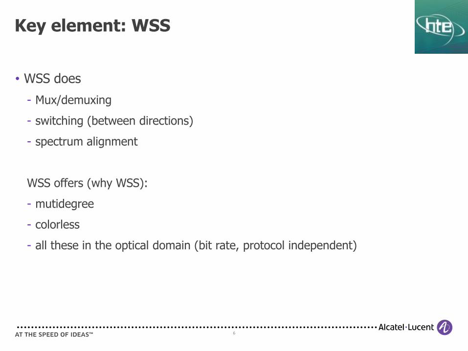
Key element: WSS
• WSS does
Mux/demuxing
switching (between directions)
spectrum alignment
WSS offers (why WSS):
mutidegree
colorless
all these in the optical domain (bit rate, protocol independent)

7
RX vs. TX WSS
RX WSS
Colorless ports by default
Less optimal for long reach
Efficient for Metro
TX WSS
Colorless ports not provided by default
Optimized for long reach
Efficient for Long Haul

8
RX WSS architectures 4-degree T/ROADM
CWR8
Filter (East) THRU
WDM IN
AMP IN
AMP OUT
WDM IN
AMP OUT
AMP IN
Filter (West)
CWR8
Xp
dr
CWR8
Filter (North) THRU
WDM IN
AMP IN
AMP OUT
WDM IN
AMP OUT
AMP IN
Filter (South)
CWR8
Xp
dr
Xp
dr
Xp
dr
Xp
dr
Xp
dr
Xp
dr
Xp
dr
FMUX
FMUX FMUX
FMUX
6 colorless ports BB
port
BB
port
BB
port
BB
port
6 colorless ports
6 colorless ports 6 colorless ports
9
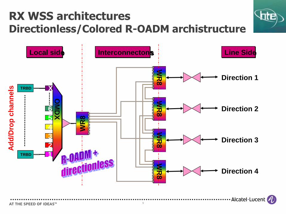
RX WSS architectures Directionless/Colored R-OADM archistructure
Local side Line Side
WR
8
WR
8
WR
8
WR
8
Direction 1
Interconnectons
Direction 2
Direction 3
Direction 4
WR
8
OM
DX
6
5
4
3
2
1
X TRBD
TRBD
Ad
d/D
rop
ch
an
nels

TX WSS based architectures Directionless/Colorless (limited) TOADM
Multiple A/D block
istances scaling up
AnyDir A/D
Block
Mesh/Thru Connections
TX WSS
MESH4
TX WSS
MESH4
TX WSS MESH4 TX WSS
MESH4
TX WSS
RX WSS
8 O
Ts
……..
TX WSS
RX WSS
8 O
Ts
Local
A/D Block
FMUX
11
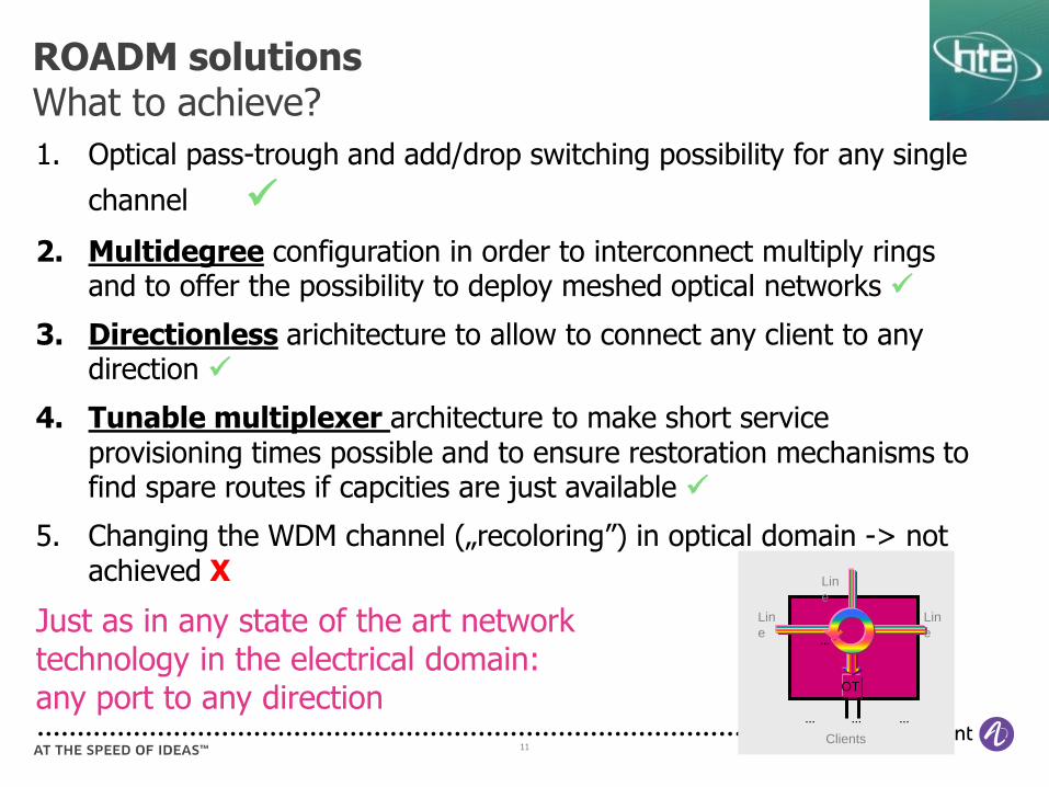
ROADM solutions What to achieve?
1. Optical pass-trough and add/drop switching possibility for any single
channel
2. Multidegree configuration in order to interconnect multiply rings and to offer the possibility to deploy meshed optical networks
3. Directionless arichitecture to allow to connect any client to any direction
4. Tunable multiplexer architecture to make short service provisioning times possible and to ensure restoration mechanisms to find spare routes if capcities are just available
5. Changing the WDM channel („recoloring”) in optical domain -> not achieved X
Just as in any state of the art network technology in the electrical domain: any port to any direction
…
Clients
Lin
e
… … …
Lin
e
Lin
e
OT
12
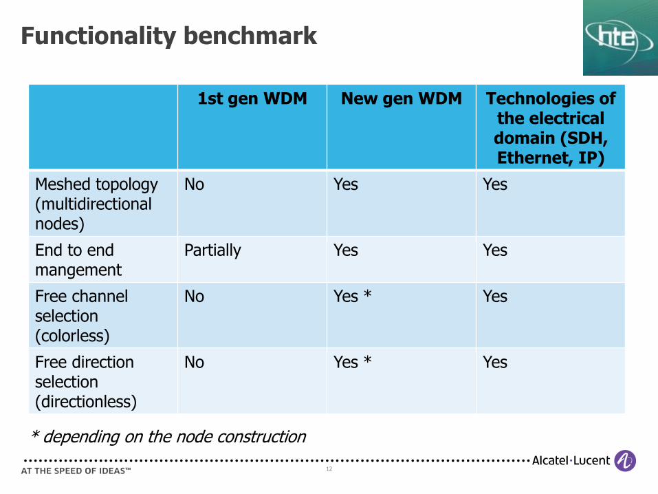
Functionality benchmark
1st gen WDM New gen WDM Technologies of the electrical domain (SDH, Ethernet, IP)
Meshed topology (multidirectional nodes)
No Yes Yes
End to end mangement
Partially Yes Yes
Free channel selection (colorless)
No Yes * Yes
Free direction selection (directionless)
No Yes * Yes
* depending on the node construction
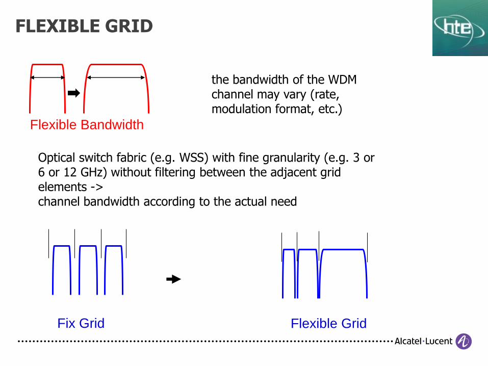
FLEXIBLE GRID
Flexible Grid
Flexible Bandwidth
Fix Grid
the bandwidth of the WDM channel may vary (rate, modulation format, etc.)
Optical switch fabric (e.g. WSS) with fine granularity (e.g. 3 or 6 or 12 GHz) without filtering between the adjacent grid elements -> channel bandwidth according to the actual need

14
1/b
Meshed operation
Wavelength tracker

Wavelength Tracker™ Operation
Each channel is encoded with a unique WaveKey pair
that allows the channel to be identified and its power
monitored
The assignment of WaveKeys is managed by the NEs,
which maintain a database of the WaveKeys used in
the network.
At each detection point, the WaveKeys are detected
and their power measured.
Integrated per-channel eVOAs
serve multiple functions
Automatic optical power
adjustment and unique
wavelength coding
Encode once, decode many times
for fault location capability
Provides a transponderless
demarcation point
Provides intra-node optical
performance monitoring
(OPM) at all line cards
Decode based on DSP, correlation
and orthogonal coding
Low Freq signal
time
frequency
Payload (noise)
Integrated
eVOA’s for
source power
management
Internal
or
Alien
Sub-carrier
modulation
DSP
DSP WT
Decode WT
Encode
Uniquely identifies each service/wavelength in the network
MU
X AMP
16
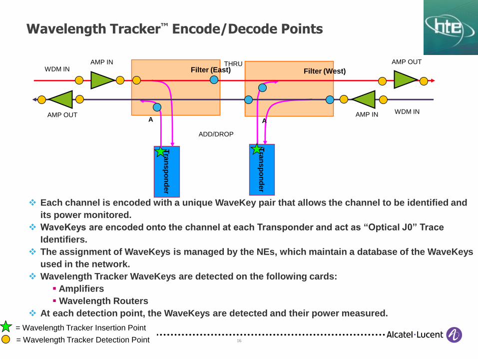
Wavelength Tracker™ Encode/Decode Points
= Wavelength Tracker Detection Point
Tra
nsp
on
de
r
= Wavelength Tracker Insertion Point
Filter (East)
A
THRU WDM IN
AMP IN
AMP OUT
Filter (West)
A
WDM IN
Tra
ns
po
nd
er
AMP OUT
AMP IN
ADD/DROP
Each channel is encoded with a unique WaveKey pair that allows the channel to be identified and
its power monitored.
WaveKeys are encoded onto the channel at each Transponder and act as “Optical J0” Trace
Identifiers.
The assignment of WaveKeys is managed by the NEs, which maintain a database of the WaveKeys
used in the network.
Wavelength Tracker WaveKeys are detected on the following cards:
Amplifiers
Wavelength Routers
At each detection point, the WaveKeys are detected and their power measured.
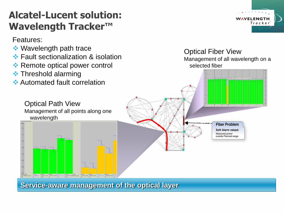
Alcatel-Lucent solution: Wavelength Tracker™
Service-aware management of the optical layer
Features:
Wavelength path trace
Fault sectionalization & isolation
Remote optical power control
Threshold alarming
Automated fault correlation
Optical Fiber View Management of all wavelength on a
selected fiber
Optical Path View Management of all points along one
wavelength
18
2.
40G, 100G, 400G
Moving foreward in system capacity
19
Increasing the system capacity
• Ways of increasing the total capacity of a WDM system:
increasing the number of channels
denser grid
broader used band
increasing the data rate per channel
using other physical properties like polarisation
20
Increasing the number of the channels
• Current status
most commonly used band: C (~1530-~1565nm) -> effectively amplified by EDFA
todays number of channels in C band:
40 (100GHz/0,8nm)
80 (50GHz/0,4nm)
10G/channel
• Increasing the number of channels
use of broader band (e.g. introducing of band L) -> rather complex (and more expensive) amplifiers, concerns in case of a migration, residual CD issues
denser grid in band C: less than 50GHz grid (e.g. 25GHz in case of 160 channels -> doubles only ones but blocks the way to higher bitrates (channel bandwidth)

21
Increasing the data rate per channel
• Needs rather complex modulation formats those of used up to 10G
Steps until now:
2,5G: simplest NRZ/RZ OOK colored signals w/o any enchancements
10G: still OOK but use of FEC to ensure similar performances (reach) as that of 2,5G
• Interoperability issues
between different modulation formats and bit rates
channel type dependent reach: rather complex system designs
By the time this way appears the most benefiting for system capacity upgrade.
• E.g. system capacities:
with 10G channels: 80x 10G: 800Gb/s
with 100G channels: 80x 100G: 8Tb/s

22
Transmission challenges beyond 10G
• Transmission beyond 10G is in general much more sensitive than 10G to the optical transmission impairments, e.g. 40G:
4 times more sensitive to optical noise (OSNR)
4 times more sensitive to fiber polarization-mode dispersion (PMD)
16 times more sensitive to fiber chromatic dispersion (CD)
more sensitive to single-channel (“intra-channel”) nonlinear effects
• So, while at 10G the plain NRZ modulation format is sufficient to cover most LH/ULH applications, at 40G alternative modulation formats are needed to overcome these limitations
Increasing transmission challenges requiring a new modulation format
23
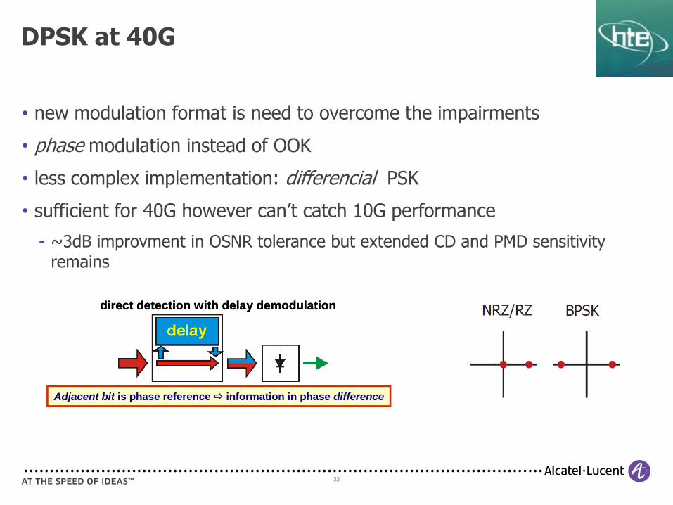
• new modulation format is need to overcome the impairments
• phase modulation instead of OOK
• less complex implementation: differencial PSK
• sufficient for 40G however can’t catch 10G performance
~3dB improvment in OSNR tolerance but extended CD and PMD sensitivity remains
DPSK at 40G
direct detection with delay demodulation
Adjacent bit is phase reference information in phase difference
direct detection with delay demodulation
Adjacent bit is phase reference information in phase difference
24
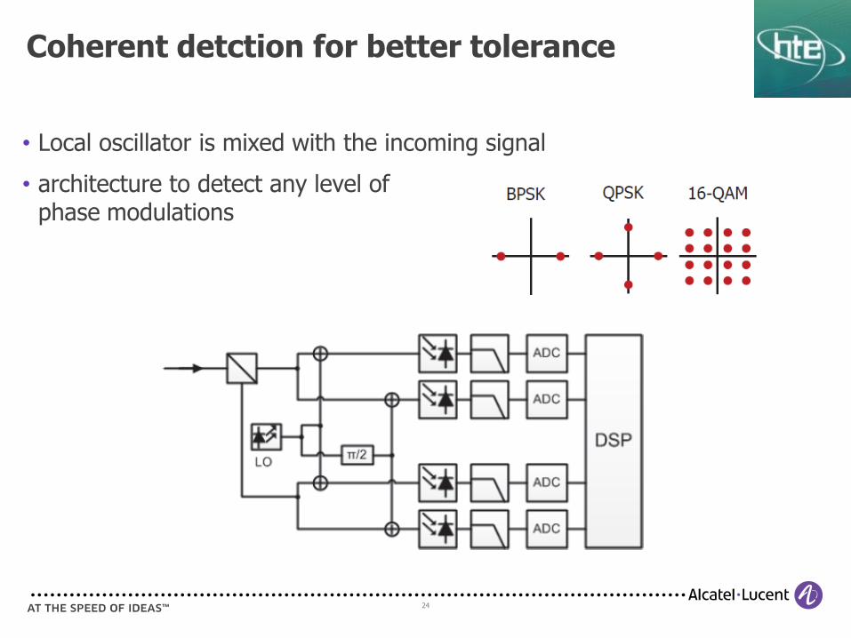
• Local oscillator is mixed with the incoming signal
• architecture to detect any level of phase modulations
Coherent detction for better tolerance
25
Dig
ital C
lock R
ecovery
Fre
quency
and C
arr
ier
Phase
recovery
Sym
bol
identi
ficati
onPola
rizati
on
Dem
ult
iple
xin
g a
nd
Equalizati
on
Fre
quency
and C
arr
ier
Phase
recovery
Re-s
am
pling
CD
com
p.
CD
com
p.
BER
& Q
²
Sym
bol
identi
ficati
on
BER
& Q
²
j
j
Dig
ital C
lock R
ecovery
Fre
quency
and C
arr
ier
Phase
recovery
Sym
bol
identi
ficati
onPola
rizati
on
Dem
ult
iple
xin
g a
nd
Equalizati
on
Fre
quency
and C
arr
ier
Phase
recovery
Re-s
am
pling
CD
com
p.
CD
com
p.
BER
& Q
²
Sym
bol
identi
ficati
on
BER
& Q
²
j
j
ADC
ADCDSP
ADC
ADCDSP
PD2
PD3
PD3
Sam
pling S
cope
PD1
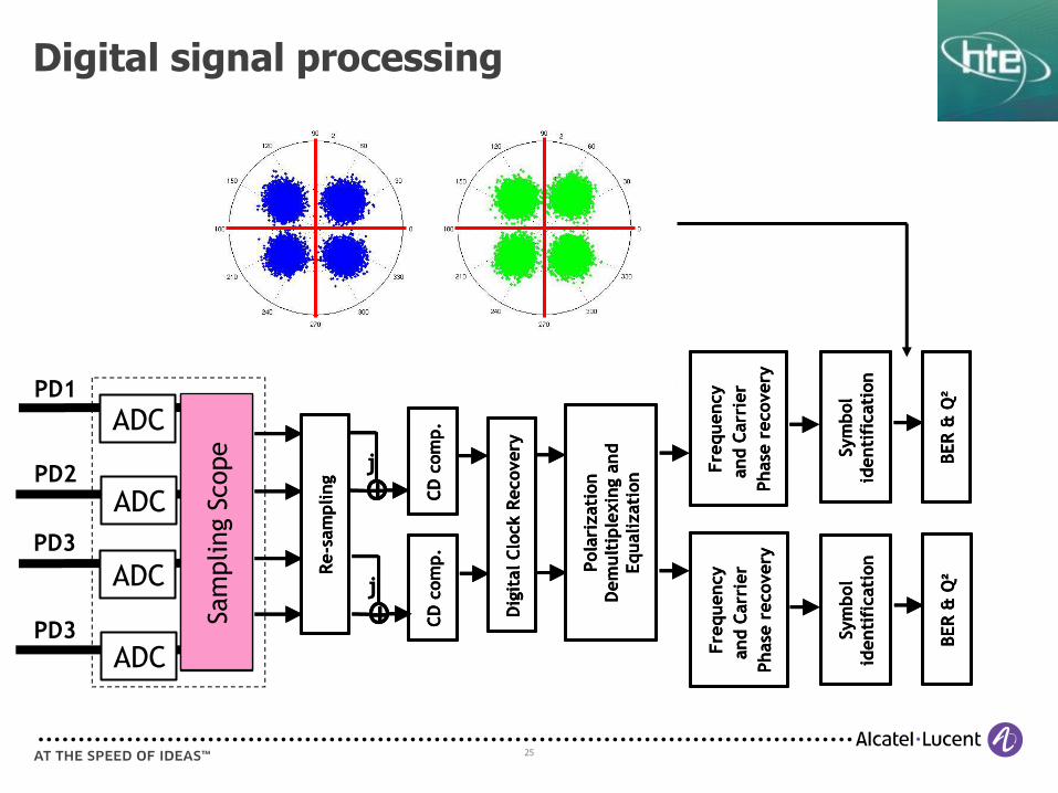
Digital signal processing

26
• Coherent detection features:
ability to detect absolute phase value
separation of polarisations (basis for polarisation multiplexing)
better sensitivity (detectors operate beside more optimal optical levels)
• DSP features:
removing (compensating) linear impairments (CD, PMD)
catching with the polarisation unstability -> enabling the polarisation multiplexing
measure of the CD and PMD: supporting operation
eliminating DCUs: in coherent only networks, less latency
w/o DCUs the high CD value along the fiber mitigates non-linear effects -> extends the reach
Rules of coherent receiver and DSP
27
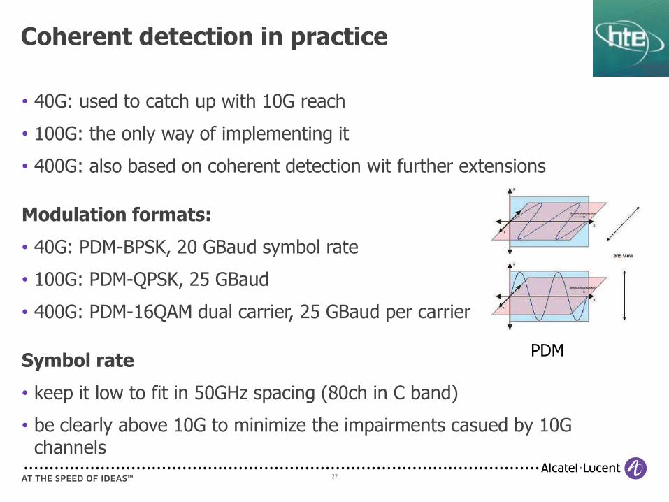
• 40G: used to catch up with 10G reach
• 100G: the only way of implementing it
• 400G: also based on coherent detection wit further extensions
Modulation formats:
• 40G: PDM-BPSK, 20 GBaud symbol rate
• 100G: PDM-QPSK, 25 GBaud
• 400G: PDM-16QAM dual carrier, 25 GBaud per carrier
Symbol rate
• keep it low to fit in 50GHz spacing (80ch in C band)
• be clearly above 10G to minimize the impairments casued by 10G channels
Coherent detection in practice
PDM

28
• Issues to solve:
100G can’t catch up in reach with pure coherent detection & DSP
400G is even more difficult
• Alcatel-Lucent’s answer: Photonic Service Engine chip
Further improvements in coherent transmission

29
400G PHOTONIC SERVICE ENGINE Working elements
Coherent Rx Enhanced algorithms Advanced frequency & phase recovery
New modulations Dynamic demodulation HD SD
Ultra-fast ADC/DAC Higher bit converter Faster sampling
Tx DSP Wave shaping

30
• Not only a firm decesion is made if the bit is „1” or „0” as in case of classical HD-FEC but a probability is also provided
• needs more overhead
SD-FEC
31
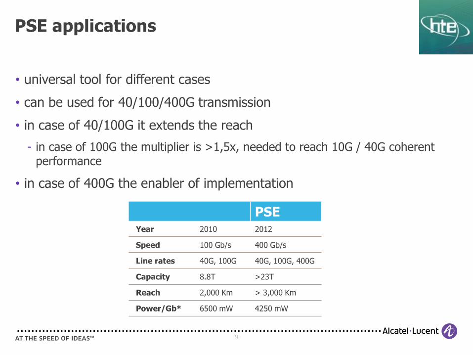
• universal tool for different cases
• can be used for 40/100/400G transmission
• in case of 40/100G it extends the reach
in case of 100G the multiplier is >1,5x, needed to reach 10G / 40G coherent performance
• in case of 400G the enabler of implementation
PSE applications
PSE Year 2010 2012
Speed 100 Gb/s 400 Gb/s
Line rates 40G, 100G 40G, 100G, 400G
Capacity 8.8T >23T
Reach 2,000 Km > 3,000 Km
Power/Gb* 6500 mW 4250 mW

32
2/b
Nonlinearities

33
-20
-15
-10
-5
0
5
10
15
20
1 3 5 7 9 11 13 15 17 19 21 23 25
Effect of nonlinearity
• Resilience to OSNR and fiber nonlinearity are key factors limiting the attainable transmission reach
• 1 dB less resilience in nonlinearity is as limiting as 1 dB less resilience to OSNR
Maximum power per channel to
limit the nonlinear effects
Minimum power per channel to
guarantee the required OSNR
Number of spans
Po
wer
pe
r c
ha
nn
el [a
.u.]
Attainable reach

34
XPM

35
Penalty by XPM