
WDM Bandwidth Allocation - McGill University · photonic slot routing, TDM/WDM assignment, and...
24
WDM Bandwidth Allocation AAPN Technical Report 2004-03 Nahid Saberi, Mark Coates Department of Electrical and Computer Engineering McGill University June, 2004
Transcript of WDM Bandwidth Allocation - McGill University · photonic slot routing, TDM/WDM assignment, and...

WDM Bandwidth Allocation
AAPN Technical Report 2004-03
Nahid Saberi, Mark Coates
Department of Electrical and Computer Engineering
McGill University
June, 2004
1 Introduction
In an all-optical network, wavelength division multiplexing (WDM) has been introduced as a meansto support the rapidly increasing bandwidth demand of the network users. Partitioning the enor-mous bandwidth in optical networks into WDM channels makes the optical bandwidth compatiblewith the speed of electronic components. In WDM systems the end users communicate via opticalchannels called lightpaths. In networks with continuity constraint a lightpath is required to occupythe same wavelength on all fiber links, while in wavelength convertible networks a lightpath canoccupy different wavelengths on different fiber links along the path. Wavelength conversion allowsnetworks to support more lightpaths, but it is expensive and difficult to implement [1]. Thereforein this study we mainly consider networks with continuity constraint.
In these networks, resource allocation is a key problem which is addressed in many differentcontexts, including routing and wavelength assignment (RWA), optical burst/packet switching,photonic slot routing, TDM/WDM assignment, and broadcast-and-select technology.
Optical backbone networks multiplex a large amount of traffic coming from numerous users oncircuit-switched wavelength paths. This technology (the so-called wavelength routing approach)has been widely studied in the literature [1]. In contrast, wavelength routing in access and metronetworks with a reduced level of traffic aggregation is not an adequate solution [2]. In these areas,other approaches such as optical burst/packet switching and time-division multiplexing over WDMchannels provide a more dynamic bandwidth allocation. Based on TDM/WDM technology severaldifferent approaches have been developed such as photonic slot routing and TDM/WDM bandwidthreservation in broadcast and select networks.
In this article we survey the background literature and recent developments in WDM resourceallocation techniques. This information provides the basis for our research which deals with resourceallocation and bandwidth sharing in a particular type of network with a star topology referred toas AAPN1 [3]. The next section introduces routing and wavelength assignment in WDM networks.Section 3 presents an overview of recent optical switching deployments. Section 4 provides anextensive description of bandwidth reservation in WDM broadcast-and-select networks.
2 Routing and Wavelength Assignment Schemes
The problem of assigning wavelengths and paths to a set of requests for bandwidth between source-destination pairs in WDM networks is referred to as the routing and wavelength assignment (RWA)problem. It has been proved that the RWA problem is NP2-Complete3 [5], and partitioning thisproblem into two subproblems, (i) routing, and (ii) wavelength assignment, makes it more tractable.Numerous solutions for either of the problems have been proposed; these can be classified understatic and dynamic approaches. Depending on the traffic pattern the problem can be formulateddifferently. When the traffic pattern is static, the requests are fixed for a long duration of time as theconnections are long-lived. Therefore, the entire demand is known in advance (off-line information).Once the connections are established there is no need for further operations. In a dynamic trafficpattern the requests arrive on-line and may depart after a while. Therefore the RWA problem has to
1Agile All-Photonic Network2Nondeterministic polynomial-time problem; a problem is said to be NP if there exists a nondeterministic
polynomial-time algorithm that recognizes the elements of this problem (i.e. that we can test in polynomial-timewhether a possible solution is a solution).
3A problem in NP is said to be NP-Complete if finding a deterministic polynomial-time algorithm for solvingthis problem allows us to solve any problem in NP in polynomial-time (for more information regarding the theory ofNP-completeness refer to [4]).
1

consider the dynamics of the related parameters for assigning paths and wavelengths to such traffic.For the routing subproblem there are three basic approaches known as fixed routing, fixed alternaterouting and adaptive routing. For the wavelength assignment component many approaches havebeen proposed so far such as First-Fit, Least-Used, Most-Used, Min-product, Least loaded, Max-SUM and Wavelength Reservation. We now present a review of various routing and wavelengthassignment approaches for both off-line and on-line cases; the review is partially derived from [1].
2.1 Routing Schemes
Many routing algorithms has been proposed in literature which can be classified in three basicgroups:
2.1.1 Fixed Routing
Fixed routing, the simplest way of performing routing in a network, chooses a fixed path from anode to each destination. Fixed shortest-path routing is an instance of the fixed routing approach,which can be implemented by using standard shortest path algorithms, such as Dijkstra’s algorithmor the Bellman-Ford algorithm. The major problem with this approach arises when the resourcesare insufficient to meet the demand, which tends to a high blocking probability [1].
2.1.2 Fixed-Alternate Routing
Fixed alternate routing constructs a list of options for routing a path between each source-destinationpair. The algorithm may use different criterions for constructing and sorting the list, such as ashortest-path criterion or the load at each link. For example, the list may include the first, thesecond and the third shortest paths between each source-destination pair. This routing approachreduces the blocking probability compared to fixed routing. In addition, in the case of path failure,it can provide some degree of flexibility for rerouting the connections [1].
2.1.3 Adaptive Routing
Adaptive routing is a routing algorithm that determines the available paths across a network andbased on the network state evaluates them and chooses the one that will provide the best path fora connection. This approach works well for networks with dynamic states. Examples of adaptiverouting include:
Adaptive Shortest-Cost-Path. This approach assigns a cost to each link in the network. Thecost is determined based on the state of the link in the network. Each unused link is assigned a costof 1 unit, each used link is assigned a cost of ∞, and each used link with a wavelength convertoris assigned a cost of c units, where the value of c is defined in such a way as to avoid the use ofwavelength convertors as long as any direct path is available. If the wavelength convertor is full(i.e., it is occupied by the other lightpaths) c = ∞ is considered. When a connection request arrives,the algorithm calculates the cost for each possible path, and chooses the one with the lowest cost.A random selection is performed for breaking the ties [1].
Least-Congestion-Path. This method determines a list of paths for each source-destinationpair. When a connection request arrives, the path with the lowest load amongst the correspondingpre-determined paths is chosen. In case of a tie, the other algorithms such as the shortest pathrouting algorithm may be performed. Since this algorithm considers all links on all pre-determined
2

paths the computational complexity is high. For reducing the complexity of this method, the authorof [6] proposed to only consider the first k links on each path (referred to as source neighborhoodinformation) where k is defined appropriately.
2.2 Fault Tolerant Routing
A common approach to protect connections against link (node) failure is to consider at least twolink-disjoint (node-disjoint) paths for each source-destination pair. In case of failure the backuppath can be used. Fixed alternate routing directly provides some reservations for each connection.In the case of adaptive routing, backups should be considered by a protection scheme, which deter-mines the alternate routes immediately after the primary connections have been established. Theprotection scheme can be the same as routing scheme with considering the cost of ∞ for undesirablelinks to promote link-disjoint (node-disjoint) paths [7].
2.3 Wavelength Assignment
Wavelength assignment is the second sub-problem within the RWA problem, and is usually ad-dressed as an independent problem. The main objective of the wavelength assignment problem isto assign a wavelength to each connection in an efficient way such that no two lightpaths on a linkshare a common wavelength. Wavelength assignment can be resolved for either dynamic traffic orstatic traffic.
2.3.1 Static Wavelength Assignment
In static wavelength assignment the lightpaths and their routes are known in advance and we needto assign wavelengths to each lightpath, such that each of the lightpaths on a given link occupiesa unique wavelength. This problem can be presented in two forms. For a given number of wave-lengths the objective is to maximize the number of connections which can be established. For agiven topology (without wavelength convertors) the main objective is to minimize the number ofwavelengths needed for a set of connection requests under the wavelength continuity constraint.The latter problem can be reduced to a sequential graph coloring problem [8].
Graph Coloring Problem. The problem of static wavelength assignment can be reduced toa graph coloring problem which is NP-Complete; among the NP problems it is the least likely tobe solved by any polynomial-time algorithm, because if there is any algorithm which solves thisproblem quickly, any problem in NP can be solved quickly by the same algorithm [4]. This provesthat the wavelength assignment problem is NP-complete itself.
The graph coloring problem constructs a graph G of nodes, such that each node correspondsto a lightpath in the network. Each common fiber between two or more lightpaths in the actualsystem is represented by a link between their corresponding nodes in the graph. The next step is tocolor the nodes of the graph in such a way that no two adjacent nodes have the same color [8]. Theminimum number of colors required by the process for coloring the graph G (the minimum numberof wavelengths) is not easy to determine. Therefore heuristics such as the sequential graph-coloringalgorithm have been introduced which are quite efficient in practice [9].
3

2.3.2 Dynamic Wavelength Assignment
Dynamic wavelength assignment considers the more realistic case where connection requests ar-rive dynamically. The connection requests are accepted if sufficient resources are available for thecomplete path and are blocked otherwise. Dynamic algorithms that consider a fixed number ofwavelengths try to minimize the blocking probability. We now summarize some of the proposedheuristics, drawing from the review material in [1].
Random Wavelength Assignment. When a connection request arrives, a search proceduredetermines the available wavelengths on the appropriate path. One of the available wavelengths israndomly selected .
First-Fit(FF). The FF algorithm numbers all of the wavelengths in the network. When a con-nection request arrives, the first available wavelength is assigned to that connection. This approachhas a very low computational complexity.
Most-Used(MU)/Pack. This method has been proposed for networks with fixed routes be-tween each source destination pair [10]. The idea is to pack connections into a fewer number ofwavelengths by selecting the most-used wavelength in the network. Packing connections is valuablein networks with the wavelength continuity constraint. In these networks there is no wavelengthconversion and reserving the least-used wavelengths reduces the blocking probability in the network.
Least-Loaded(LL). LL has been designed as a wavelength assignment technique for multi-fibernetworks [11]. For each connection request the most-loaded link of multi-fibers along the requiredpath is looked over by the algorithm to determine the least-loaded wavelength on this link. Theleast-loaded wavelength on a multi-fiber network is the one with the largest residual capacity. Theresidual capacity of each wavelength may vary between 0 and N , where N is the number of fiberson each link.
MAX-SUM(MΣ). This method also has been proposed for multi-fiber networks [10, 12]. MΣconsiders all the routes in the network that might be used by any of the connections. Then for arequest the algorithm selects a wavelength on the selected path in such a way that the maximumavailable capacity on the remaining paths is obtained.
Wavelength Reservation(RSV). A wavelength reservation scheme reserves a specific wavelengthon the links along a path of a multi-hop stream. This approach reduces the blocking probabilityfor multi-hop streams, although the blocking probability for single-hop streams may increase.
3 Switching Schemes in WDM Systems
In addition to routing and wavelength assignment several different technologies have been developedfor the transfer of optical data over WDM networks, such as optical packet switching, optical burstswitching, and photonic slot routing. In this section we look at these switching technologies.
3.1 Photonic Slot Routing
Photonic Slot Routing(PSR) is a time division multiplexing approach for all-optical access andmetro networks. PSR attempts to reduce complexity by eliminating the use of individual wavelength
4

switching (IWS) components. The time-shared nature of this approach provides a sufficient levelof traffic aggregation in networks for which the wavelength routing solution is inefficient. We nowexamine a photonic slot routed network which has been designed by Zang et al. [13].
3.1.1 Photonic Slot Routing in All-Optical WDM Mesh Networks
In PSR, time is slotted into fixed spans, each comprising a photonic slot. A photonic slot includesall wavelengths in a network. The packets of data destined for the same node are loaded into thephotonic slots and are sent as a single integrated unit. Therefore there is no need for individualwavelength routing along a path and wavelength insensitive components are adequate for routingthe photonic slots. Eliminating the use of wavelength demultiplexers results in faster switching,less complexity and lower cost [13].
Network Architecture. In this design a mesh network of wavelength insensitive nodes (Fig-ure 1) is considered. At the source end, each node considers a separate electronic buffer spacefor each destination. The photonic slots for each destination consist of several data packets on anumber of wavelengths and a header on a different wavelength. At each intermediate node headersare extracted from slots. During the header processing period the data slots travel along delaylines. To avoid the need for delay lines a solution is to send the header of a slot a fixed period oftime before the payload, long enough for processing the header. The headers contain informationabout the wavelengths being used by the slot and the destination addresses. When a header of aslot arrives at a node which has some packets headed for the same destination, the node may insertits packets to the free wavelengths of the arriving slot. Inserting the packets can be done by usingcouplers.
When two or more arriving slots contend for the same output port several techniques may beused such as optical buffering, deflection routing, or dropping the slots randomly.
3.1.2 PSR Protocol
When a node has several packets to send, it may choose to add its packet to an arriving slot headedfor the same destination or it may place the packets in an empty slot and sign the slot for itsdestination. There are a number of policies for slot assignment and adding packets to the existingslots. A slot may be occupied entirely by a node or may be left with some free spaces to be usedby intermediate nodes. Here two types of slot assignment policies are introduced.
Packet Arrival Based Assignment Policy. Upon receiving an empty slot a node randomlychooses one of its queues and inserts a number of packets into the slot. This policy implies thatas long as there are empty slots or free space in arriving slots with the appropriate destination thenode is allowed to insert its packets. However this approach results in unfairness in resource allo-cation as well as high probability of blocking. Nodes located in the internal regions of the networkusually receive assigned or full slots, while nodes located towards the edges of the network usuallyreceive empty slots.
Capacity Allocation. A straightforward method for capacity allocation is the slot preassign-ment approach proposed by Chlamtac et al. [14]. In this approach a TDMA frame consisting of Lslots is considered, in which a fixed number of slots is assigned to each source-destination pair. Thenumber of slots for each pair is determined by using a network-wide TDMA schedule to achieve fair-ness and contention free slot routing at intermediate nodes. However this approach is not practical
5

Figure 1: Photonic Slot Routing (PSR) node architecture; each node is capable of buffering, headerprocessing, and packet insertion. A packet on wavelength λ2 is inserted into an arriving photonicslot which is free at λ2 [13].
since the length of the frame is fixed and the number of slots per pair is always an integer number.An alternative method [13] is to assign destinations probabilistically to arriving slots based on thecapacity allocation results. This approach consists of two steps: the “Capacity-Allocation” step inwhich the fraction of the capacity of a link for each source-destination pair is determined, and the“Slot-Assignment” step in which a destination is assigned to each slot based on the results of thefirst step.
3.2 Optical Packet Switching
Optical packet switching (OPS) offers a better bandwidth granularity compared to the circuitswitched networks, which results in a finer transmission, a bandwidth-efficient design and a moreflexible all-optical network. However, this technology faces a number of limitations, in that opticalpacket switching requires optical buffering and packet-level processing [15].
An optical packet network consists of interconnected optical packet switches which are mainlycomposed of four parts: the input/output interfaces, switching fabric and control unit. The inputinterfaces align the packets, extract the header information from the packets and remove the head-ers. The control unit arranges the control functions based on the header information. The switchfabric switches the packets optically based on the control information. The output interfaces areresponsible for optical signal regeneration and header insertion [15]. Header processing must beperformed in the electrical domain, while the payload remains in the optical domain. Thereforepackets have to be stored in the switch (e.g., using Optical Delay Lines (ODLs)) to be forwardedto the next stage when the header processing is complete, referred to as store-and-forward natureof packet switching.
6

3.2.1 Contention Resolution in Optical Packet Switching
Whenever two or more packets are destined to the same output port at the same wavelength, ex-ternal blocking occurs. Optical packet switches are mostly non-blocking designs, therefore internalblocking is not an issue. To resolve contention in optical packet switches several approaches havebeen introduced including optical buffering, wavelength convertors, and deflection routing.
Optical Buffering. Optical delay lines are currently the only way of implementing optical buffers.Using electrical buffering is not acceptable, since electronic components can-not catch up with op-tical speeds. Optical buffers can be implemented by several ODLs with variable lengths to providedifferent delay lines. A counter is used to keep track of the number of packets in the buffer. Using aseparate counter for each ODL adds flexibility to the use of optical buffers and reduces the length ofthe delay lines (i.e., a packet may be circulated through several ODLs to achieve the desired delay).Implementing optical buffers needs an enormous amount of fiber and a complex electronic control.In addition, optical signals travelling through delay lines may experience a considerable power lossso that optical amplifiers are necessary. The accumulated noise due to cascaded amplifiers limitsthe network size or requires signal regeneration, which is expensive. For more details about recentadvances in optical buffering see Shun et al. [16] and Harai et al. [17].
Wavelength Convertors. Wavelength convertors can be used to reduce the number of delaylines, by converting the wavelength of a contending packet to a free wavelength at the output port.In a switch capable of optical buffering and wavelength conversion, the input is demultiplexed andeach packet is sent to an appropriate destination (e.g., an output port). In the case of contention,a non-blocking space switch may send a packet on an available wavelength at the output port byusing wavelength convertors or it may delay the packet. However wavelength convertors are expen-sive and full conversion is not easy to achieve [16].
Deflection Routing. Deflection routing resolves the contention by sending one of the contendingpackets to the desired link and passing the rest through any available link. The deflected packetsare routed at the other nodes to their destination. This way packets of the same source-destinationmay experience different routes with different number of hops, which affects the network perfor-mance. Deflection routing usually is used in conjunction with optical buffering to reduce the needfor buffering and to avoid too many recirculations at delay lines, which gives rise to signal to noiseratio degradation [16]. In the simplest method of deflection routing, delay lines are not used at all(see the hot-potato routing approach [18]).
3.2.2 Synchronous and Asynchronous Optical Packet Networks
Optical packet networks can be divided into two main categories: synchronous (slotted) and asyn-chronous (unslotted) frameworks. In the slotted case all the packets are aligned before they enterthe switch. Whether or not the network is synchronous, bit-level synchronization and fast clockrecovery are necessary at the switching stage for header recognition and packet delineation [16].
Synchronous Optical Packet Networks. In a slotted network the packet size is fixed. Eachpacket and a fixed guard time should fit into a fixed length time-slot. Therefore the packets arriv-ing at the switch are aligned in phase with a local clock reference. In such a network contentionis mostly resolved by using optical delay lines with propagation delays equal to a multiple of thetime-slot duration [16].
7
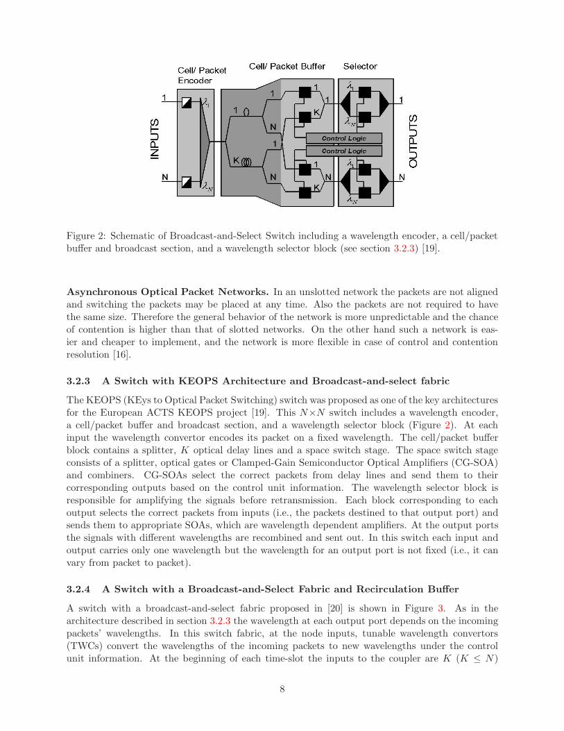
Figure 2: Schematic of Broadcast-and-Select Switch including a wavelength encoder, a cell/packetbuffer and broadcast section, and a wavelength selector block (see section 3.2.3) [19].
Asynchronous Optical Packet Networks. In an unslotted network the packets are not alignedand switching the packets may be placed at any time. Also the packets are not required to havethe same size. Therefore the general behavior of the network is more unpredictable and the chanceof contention is higher than that of slotted networks. On the other hand such a network is eas-ier and cheaper to implement, and the network is more flexible in case of control and contentionresolution [16].
3.2.3 A Switch with KEOPS Architecture and Broadcast-and-select fabric
The KEOPS (KEys to Optical Packet Switching) switch was proposed as one of the key architecturesfor the European ACTS KEOPS project [19]. This N×N switch includes a wavelength encoder,a cell/packet buffer and broadcast section, and a wavelength selector block (Figure 2). At eachinput the wavelength convertor encodes its packet on a fixed wavelength. The cell/packet bufferblock contains a splitter, K optical delay lines and a space switch stage. The space switch stageconsists of a splitter, optical gates or Clamped-Gain Semiconductor Optical Amplifiers (CG-SOA)and combiners. CG-SOAs select the correct packets from delay lines and send them to theircorresponding outputs based on the control unit information. The wavelength selector block isresponsible for amplifying the signals before retransmission. Each block corresponding to eachoutput selects the correct packets from inputs (i.e., the packets destined to that output port) andsends them to appropriate SOAs, which are wavelength dependent amplifiers. At the output portsthe signals with different wavelengths are recombined and sent out. In this switch each input andoutput carries only one wavelength but the wavelength for an output port is not fixed (i.e., it canvary from packet to packet).
3.2.4 A Switch with a Broadcast-and-Select Fabric and Recirculation Buffer
A switch with a broadcast-and-select fabric proposed in [20] is shown in Figure 3. As in thearchitecture described in section 3.2.3 the wavelength at each output port depends on the incomingpackets’ wavelengths. In this switch fabric, at the node inputs, tunable wavelength convertors(TWCs) convert the wavelengths of the incoming packets to new wavelengths under the controlunit information. At the beginning of each time-slot the inputs to the coupler are K (K ≤ N)
8

Figure 3: A Switch with a Broadcast-and-Select Fabric and Recirculation Buffer (see section 3.2.4)[19].
incoming packets plusM−K inputs which are feedback from the 1 time-slot delay line. The couplercombines the input wavelengths and splits them into tunable optical filters (TOFs) (N < MTOFs are available) and fixed optical filters (M fixed optical filters are available). According tothe packets’ destination the control unit determines up to N packets to be sent out through NTOFs and the remaining packets are delayed and recirculated through 1 time-slot delay line. Therecirculated packets form part of the input to the coupler at the beginning of the following slot.
3.2.5 Architecture with a Wavelength Routing Switch Fabric
Many switch architectures based on wavelength routing have been proposed in the literature [21].The switching procedure in most of them includes using ODLs for contention resolution, androuting the packets to the correct output ports through the wavelength switch fabric. Here wereview an architecture with an input-buffered switch fabric [22]. As Figure 4 shows this switch iscomposed of scheduling and switching sections. In the scheduling section each incoming wavelengthis passed through a TWC and then the two K × K arrayed waveguide gratings (AWGs), whereK = max(N,M). The AWGs are responsible for switching the optical signals from input ports tooutput ports. Each incoming and outgoing port carries a single wavelength. At each output portthe wavelength varies with the packet. Between the two AWGs, M ODLs are used to resolve eitherinternal or external contention. This architecture implements N individual buffers (correspondingto N different incoming wavelengths), each of which incorporates M positions. Each TWC convertsthe wavelength of the incoming packet to another wavelength in such a way to meet an ODL with anappropriate delay (each delay line has a different fixed wavelength). The ODLs are selected so thatno two packets appear at the output of any ODL or the switch at the same slot. After the packetsexperience appropriate delays they are forwarded to their destination output ports through TWCsand AWGs. TWCs assign the appropriate wavelength to each outgoing packet corresponding to itsdestination port. Using wavelength convertors reduces complexity in the switching section.
3.3 Optical Burst Switching
Optical Burst Switching (OBS) tries to combine circuit and packet switching while avoiding theshortcomings of each. OBS is based on a one-way reservation scheme in which bursts of datafollow control packets without waiting for acknowledgment [23]. Using OBS there is no need foroptical-electrical-optical (O/E/O) conversion as in optical circuit switching, and similar to packet
9

Figure 4: An input-buffered switch including Array Waveguide Gratings (AWGs) for switching theoptical signals and Tunable Wavelength Convertors (TWCs) [22].
switching techniques it enables the network to share the resources among a number of users andincrease the bandwidth utilization. In OBS the control packets are sent before the burst of data,so they are processed before the data arrives at the intermediate nodes. Consequently there is noneed for data buffering as in packet switching. Moreover aggregating the packets as a burst reducesthe overhead due to control packets. However, OBS is subject to a significant packet loss and burstretransmission. In the following we describe some proposed approaches for this switching method.
3.3.1 Optical Burst switching for Service Differentiation in the Next-Generation Op-tical Internet
The author of [23] surveys various designs for an optical burst switch network . In OBS the con-trol packets representing a burst of data are processed at each node along a predetermined routeto establish a lightpath by configuring the WDM switches. Then the corresponding burst passesthrough the pre-configured lightpath. There are three different techniques for burst switching,called, tell-and-go (TAG), in-band-terminator (IBT), and reserve-a-fixed-duration (RFD). Amongthese techniques the third one has been studied for all-optical networks [23]. RFD is the basisfor an optical burst switching protocol called Just-Enough-Time (JET) [24], which is described asfollows:
An OBS Protocol using Offset-Time and Delayed-Reservation (Just-Enough-Time).The basic functionality of this protocol is shown in Figure 5. The header of each burst is sentbefore the payload by a “base” offset time, T ≥ ΣH
h=1δ(h), where δ(h) is the expected control
delay at hop 1 ≤ h ≤ H. In Figure 5, H=3 and δ(h) = δ. In the JET-based control protocol thebandwidth at each hop is reserved from burst arrival time, ts, until burst departure time, ts + l,where l is the length of the burst. At hop i, the burst arrival time is the summation of ta, the timeat which the control packet processing has been finished, and T (i) = T − Σi
h=1δ(h) which is the
remainder of the offset time at hop i (i.e. ts = ta + T (i)). If the reservation fails due to contentionwith other requests, the burst will be blocked. Blocking may be resolved by using ODLs. If ODLsare not available then the burst will be dropped [23].
An Offset-Time-Based QOS Scheme. This scheme uses an “extra” offset-time for supportingclass isolation (or service differentiation) with or without ODLs [25]. Suppose that there are onlytwo classes of traffic, class 0 and class 1, where class 1 has the highest priority. For the class 1
10

Figure 5: The use of offset time, and delayed reservation in JET-based OBS: (a) the burst followsthe control packet after a base offset time, T; (b) the bandwidth is reserved from the burst arrivaltime, ts [23].
Figure 6: Class isolation at an optical switch without ODLs: (a) shows the case where request 1has arrived before request 0; and (b) shows the case where request 0 has arrived before request1 [23].
bursts, an extra offset time, t1o is considered. The base offset time is considered negligible comparedto this extra time. Let tia and tis be the arriving time and the service start time for a class i request,respectively, and li be the length of the request. To show how the class differentiation schemeworks, we consider the following cases without ODLs (Figure 6):
Case 1, where the request 1 has arrived before request 0, t0a > t1a (Figure 6-(a)):if t0a + l0 ≥ t1s ≥ t0a or t1s ≤ t0a ≤ t1s + l1 the class 0 request will be droppedelse, the request 0 will be succeed.
Case 2, where request 0 has arrived before the request 1, t1a > t0a (Figure 6-(b)):if t1a + t1o < t0a + l0 request 1 will be dropped.
To avoid blocking of class 1 requests, t1o needs to be larger than the maximum burst length inclass 0. When ODLs are available the problem is more complicated but by choosing an appropriateoffset time, class 1 can be isolated from class 0 requests in reserving both bandwidth and ODLs [23].
11

Figure 7: Time-sliced packet switched network architecture, composed of a network of TSOBSs andconcentrators; concentrators transmit user data bursts in time-division channels. Data is carriedon the WDM link within frames comprised of fixed length time-slots [7].
3.3.2 Time Sliced Optical Burst Switching
Time Sliced Optical Burst Switching (TSOBS) is an approach proposed by Ramamirtham et al. [7],which replaces wavelength domain switching with time domain switching. This eliminates the needfor wavelength converters and results in a lower cost. TSOBS also reduces the number of delaylines required for supporting burst switching by using blocking Optical Time-Slot Interchangers(OTSI) and Optical Crossbars.
TSOBS Networks. Figure 7 shows the architecture of a time-sliced optical burst switched net-work. Terminals or other networks are connected to the TSOBS network by concentrators. WDMlinks connect the network of time-sliced optical burst switches. The information on each wavelengthis organized into a series of frames of fixed length time-slots. Concentrators transmit user datapackets (packet switching) or aggregated user data (burst switching) in time-division channels. TheBurst Header Cells (BHC) are carried on separate control wavelengths. If the ratio of the averageburst length to the BHC length is L, each control wavelength can support L− 1 data wavelengths.Each BHC carries information about the length of the burst, source-destination addresses, wave-length, and the identification of the first frame in which the data burst appears. It also includes afield in which the distance travelled by a burst and the number of optical operations since its lastregeneration are recorded. This information is used to regenerate the burst before too much signaldegradation arises due to noise and signal attenuation at each switching stage [7].
Optical time-slot Interchangers. OTSIs perform time domain switching in the TSOBS ar-chitecture. They can be used in either non-blocking or blocking designs. The simplest form of anon-blocking OTSI has N delay lines and an (N + 1)× (N + 1) optical crossbar switch (see Figure8) , where N is the number of time-slots in each frame. Delay lines provide 1, 2, · · · , N time-slotsinterval delay. A more practical design for a non-blocking switch has been introduced in [7]; thedesign uses 2
√N − 2 delay lines and a (2
√N − 1)× (2
√N − 1) crossbar switch. In order to reduce
the cost and complexity of switches, blocking OTSIs can be used. For this design N/2 delay linesprovide 1, 2, 4, · · · , N/2 time-slot delays. A small crossbar switch (
√N ×
√N) is needed to support
switching operations between the delay lines as well as the incoming time-slots. Thus the number of
12

Figure 8: Optical time-slot Interchanger, which performs time-domain switching; each OTSI con-tains a set of optical crossbars for switching time-slots among the inputs, outputs and a set of delaylines. The signals are demultiplexed to perform the switching operations and remultiplexed ontothe delay lines, allowing the cost of the delay lines to be shared by the different wavelengths [7].
switching operations increases as the switch is subject to blocking. When a time-slot arrives at theswitch, a search procedure is performed to find an available sequence of delay lines for creating thedesired delay for that slot. For this task the state of the delay lines must be tracked and recordedin a scheduling array. To find the best delay path, a shortest path tree algorithm is performed.This algorithm finds the path with the smallest number of switching operations which is neededto obtain the desired delay. Blocking OTSIs can be presented with different number of delay linesand crossbar switches. Therefore each design has a different cost and blocking probability [7].
Switch Architecture. Figure 9 shows the overall design for a TSOBS router. The router con-sists of synchronizers, OTSIs, a central optical crossbar, a controller and WDM multiplexors. Thesynchronizers can be implemented using a space-division optical switch and a finely calibrated setof delay lines to synchronize the incoming frames to the local clock. The performance evaluationsshow that the blocking design performs very close to non-blocking switches while the cost is im-proved significantly due to a small number of delay lines needed to provide an acceptable blockingprobability. OTSI separates the control wavelengths and forwards them to the controller. Thecontroller processes the BHC information and passes the results to optical crossbar switch as wellas the OTSIs. When a BHC arrives at the controller, the controller determines the appropriateoutgoing link for that burst. Then on the outgoing links and the output of the corresponding OTSIa look up procedure defines the available time-slots on the wavelength being used by the burst.OTSI then provides time domain switching for all wavelengths available on each link based on theinformation about the available time-slots on the outgoing links. It separates the data wavelengthsand sends each one on a different fiber to the optical crossbar after the appropriate time domainswitching is performed. The number of delay lines used in OTSIs is the key parameter affectingboth the performance and the cost of the TSOBS switches. The optical crossbar performs spaceswitching on individual wavelengths and WDM multiplexors combine the data wavelengths withcontrol wavelengths on the outgoing links.
13

Figure 9: The overall Time-Sliced Optical Burst Switch Design; each incoming WDM link termi-nates on a Synchronizer (SYNC) which synchronizes the incoming frame boundaries to the localtiming reference. Optical Time Slot Interchangers (OTSI) provide the required time domain timingof switching operations on the data wavelengths [7].
4 Bandwidth Reservation in WDM systems
In an all-optical communication system, wavelength division multiplexing (WDM) has been intro-duced to use the substantial optical bandwidth efficiently by partitioning the optical bandwidthinto WDM channels compatible with the speed of electronic processing. WDM systems can incor-porate time-division multiplexing (TDM), which provides WDM access to many end-users sharingthe optical channels in the time domain, and therefore makes optical networking practical.
In order to effectively facilitate multiple access to the network resources, bandwidth reservationcan be used as an admission control mechanism. Bandwidth reservation uses at least one channelfor reservation and the rest are allocated to data transmissions [26]. Reservation can be performedin several forms including burst switching and fixed time-slot assignment. In a burst switchingmodel the bandwidth is requested before transmitting the burst of data, while the data is usuallytransmitted after a period of time, without waiting for acknowledgment [23]. The waiting time isconsidered just long enough for processing the request of bandwidth on an appropriate outgoinglink, which should be done in relation to the other contending requests. In fixed time-slot schedulingthe time is divided into small partitions called slots, which are assigned to the requests ahead oftime. Therefore in this model the transmission is performed after receiving the approval from thecontroller. In time-slot scheduling, the assignment can be accomplished using many varieties ofscheduling algorithms.
Scheduling algorithms can be designed in an on-line [26–28] or off-line [29–31] manner, each ofwhich involves a different set of requirements and techniques. An on-line (or incremental) schedulingalgorithm computes a schedule based on the available partial information for each arriving request.During the reservation phase, as soon as the first request arrives the scheduler starts computation.This technique has a relatively low computation time, but the result is not always optimal [26].On the other hand the off-line scheduling algorithms need the entire traffic demand matrix tostart computing the schedule. The demand matrix whose (i, j)-th element represents the numberof (fixed-size) packets that must be transmitted from source i to destination j, can be collectedduring the reservation phase (in a dynamic traffic scenario) or the algorithm might consider ana priori traffic distribution pattern (in a static traffic scenario) [27]. In the latter case referred to
14

as static scheduling, the traffic demand changes do not affect the schedule [26].Depending on the traffic pattern the scheduling problem can be solved for a fixed frame length
or a variable frame length. The variable frame length structure does not suit connections whichneed reservations for several consecutive frames. In long term transmissions the users usuallyspecify their requests in bits per second. Therefore changing the frame length changes the user’sthroughput if the number of slots per frame allocated to a user is not changed. Consequently thevariable frame length formalization is more suitable for one-shot transmissions [32].
4.1 Bandwidth Reservation in Star Coupled Networks with tunable transmit-ters/receivers
Many algorithms have been proposed so far for bandwidth reservation in an all-optical broadcast-and-select network with a star topology [30, 32–36]. In this network a star coupler provides theconnections between several nodes, which are equipped with tunable transmitters and/or tunablereceivers. In general, the number of nodes is greater than the number of available channels, andtherefore the transmitters have to share the channels using a reservation-based technique. Depend-ing on the efficiency requirements and the traffic pattern the scheduling problem can be solved foreither off-line or on-line formalization and variable or fixed frame length.
4.2 Variable Frame length
The scheduling problem for WDM networks with tunable transmitters /receivers and variableframe length has been extensively analyzed [30, 32–34]. The proposed algorithms try to optimizethe schedule while delivering all traffic within the next frame. This problem is usually formalizedas follows [35]:
“Given a traffic matrix D whose elements Dij are the numbers of (fixed-size) packetsthat must be transmitted from any source user i to any destination user j, find atime/wavelength assignment that guarantees the delivery of all traffic, while mini-mizing the time necessary to accommodate all transmissions (the frame duration),subject to tuning delay constraints.”
The main objective of a scheduling algorithm is to minimize the computation time while maximizingthe utilization of the network resources. In this particular network with a variable frame length,increasing the utilization is equivalent to reducing the schedule length. The lower bound on theschedule length is given by maxi,j{Si, Rj}, where Si =
∑Mj=1
Dij is the i-th column sum and
Rj =∑M
i=1Dij represents the j-th row sum. It has been shown that the algorithms aimed at
minimizing the transmission schedule length have polynomial-time complexity [37]. Also it hasbeen shown that minimizing the effect of tuning latency on the schedule length while minimizingthe transmission time is an NP-hard4 problem [38]. In [30,32–34] several heuristic approaches havebeen proposed which aim at minimizing the frame duration with the assumption that all of therequests are assigned. In the following we introduce two simple algorithms for the variable-frameproblem in a star-coupled network with tunable transmitters and receivers.
4.2.1 Heuristic Approaches
We now review two reservation-based scheduling techniques for WDM star networks [39]: SEQSAM(SEQuential Scheduling AlgorithM) and BALSAM (BALanced Scheduling AlgorithM). The net-
4A problem is NP-hard if solving it in polynomial time would make it possible to solve all problems in class NPin polynomial time.
15

work architecture is based on a passive star topology composed of M nodes which are equippedwith tunable transmitters and receivers capable of operating on C channels. Frame transmissionincludes a reservation phase, a schedule computation phase, and a data phase. During the TDM-based reservation phase, all the nodes broadcast their information (i.e. a control packet containingthe destination identification and the requested packet size is sent to every node in the network).This can be done by tuning all the transmitters and receivers on a single channel. At the end of eachreservation phase an M ×M demand matrix, D, whose (i, j)-th element, Dij denotes the demandfrom node i to destination j, is available. During the schedule computation phase a transmissionschedule is computed at every node. The scheduling problem is to specify the durations in whicheach transmitter and receiver should tune to a specific channel during the data phase.
SEQSAM allows receivers to tune on multiple channels during each transmission phase. Butthis technique has a very low performance and is introduced in [34] primarily to show the perfor-mance improvement that can be achieved by the other algorithm, BALSAM. BALSAM restrictsthe receivers to tune on only one channel during each transmission phase. This restriction reducesthe effect of tuning latency on the transmission time.
SEQuential Scheduling AlgorithM (SEQSAM). SEQSAM groups the elements of the M×Mdemand matrix into groups of C elements, producing G sub-matrices. Each of the sub-matriceshas at most C nonzero elements with no more than one nonzero element on any row or column.Therefore the lower bound on G is given by (M2−M)/C. SEQSAM implements a simple techniquefor obtaining the matrix decomposition, but its average time complexity is O(M3). Scheduling inSEQSAM takes place after grouping the elements and obtaining G sub-matrices:
D = D1 +D2 +D3 + · · · +DG
The length of the transmission phase is the sum of the largest entries in the sub-matrices (Dimax)
defined as∑G
i=1Di
max.
Example 1. Consider a star network with M = 4, C = 2 , and the following demand matrixand its decomposition:
D =
0 3 2 21 0 4 13 2 0 11 1 3 0
=
0 3 0 01 0 0 00 0 0 00 0 0 0
+
0 0 2 00 0 0 10 0 0 00 0 0 0
+
0 0 0 20 0 4 00 0 0 00 0 0 0
+
0 0 0 00 0 0 03 0 0 00 1 0 0
+
0 0 0 00 0 0 00 2 0 01 0 0 0
+
0 0 0 00 0 0 00 0 0 10 0 3 0
In this example the matrix is decomposed into G = 6 groups of C = 2 nonzero elements. Eachsub-matrix is assigned a section of time slots on the transmission schedule. The length of eachsection is equal to the largest entry of the corresponding sub-matrix. On each sub-matrix the firstchannel is assigned to the first non-zero entry. The next channel is assigned to the next non-zero
16

N0 N0 N2 N0 N2 N2
N1 N1 N1 N3 N3 N3
Figure 10: Example 1: Allocation schedule of two available wavelengths (shown by two differentcolors) achieved by SEQSAM. Ni denotes the source node i, and the schedule length is 17 timeslots.
entry and so on. The schedule length (as we see in Figure 10) is 17 slots.
BALanced Scheduling AlgorithM (BALSAM). This algorithm converts the M × M de-mand matrix to an M ×C matrix by using the Modified Multi-FiT (MMFT) algorithm [40]. Thenusing an interval-based scheduling algorithm it assigns the channels to the transmitters. BALSAMattempts to reduce the schedule length by reducing the effect of tuning latency and the wasted re-sources during each frame. It has been shown in [36] that the time complexity of the Interval-BasedScheduling Algorithm (IBS) is O(MC2K ′) where K ′ is the largest element in the M × C demandmatrix. A simple description of this algorithm is as follows. At the first step the MMFT algorithmcomputes the column sums of the demand matrix and sorts the columns in descending order. Thenit assigns each of the first C columns to each of the C channels and starts over with assigning thesecond C columns to the C channels and so on. So for C < M several columns are given a commonchannel, and each receiver (corresponding to each column) has to tune on the selected channel.With this technique the load is almost equally distributed on the available channels, and we havean M × C demand matrix, whose (i, j)-th element represents the number of requested time slotsfrom node i on channel j. The IBS algorithm for the M × C demand matrix keeps track of theavailable intervals on the channels. When a node request for a channel is considered, the algorithmtries to fit the request in the first available interval. If the interval is not sufficient to be allottedto the demand the next available interval is considered. The following example explains how thisalgorithm operates.
Example 2. Consider the demand matrix in the previous example. Using MMFT the 4 × 4demand matrix is converted to the following 4×2 demand matrix which shows the demand of eachtransmitter for each channel. For more information regarding the MMFT algorithm refer to [39].
4 35 11 53 2
Node 0 request: IBS first considers the request of node 1 for channel 1 which is 4 slots. Initially allof the slots are available. Therefore the first 4 slots are allotted to the first request of node 0. Thenext request to be considered is the node 0 request for channel 2. Since the transmitter has beentuned to channel 1 during the first 4 time slots, the first possibility for transmission on channel 2is the interval [5,7].Node 1 request: For the next request, node 1 on channel 1, the available intervals are [5,∞]. There-fore the interval [5, 9] is assigned to this node. Similarly the node 1 request for channel 2 has to
17

N0 N1 N3 N2
N1 N3 N0 N2
Figure 11: Example 2: Allocation schedule of two available wavelengths (shown by two differentcolors) achieved by BALSAM. Ni denotes the source node i, and the schedule length is 15 timeslots.
T N0 N0 N0 N0 T T N0 N0 T T T
N1 N1 T T T T N1 N3 N3 T T N3
N2 N2 N2
Figure 12: Example 1: Allocation schedule of two available wavelengths (shown by two differentcolours/shadings) achieved by SEQSAM incorporating the tuning latency for T=1. Ni denotessource node i, and the schedule length is 23 time slots.
be assigned based on a look up procedure which determines the first fit interval in the schedulingtable. In this example the first slot on channel 2 suits this request. For the rest a similar procedureis performed. Figure 11 shows the final transmission schedule. The schedule length in this exampleis 15 slots.
Tuning Latency. This section considers the effect of tuning latency on the transmission time forthe two proposed algorithms. Let Tt denote the number of slots required for tuning the transmitterbetween the channels, and Tr denote the tuning latency of the receivers. We define T = max{Tt, Tr}.For SEQSAM there are G sub-matrices and transceivers tune to their assigned channels betweenthe sub-matrices. Therefore the additional delay introduced by SEQSAM due to tuning latency isGT (Figure 12).
BALSAM introduces less tuning latency to the transmission phase since the receivers assignmentto the channels is static during each frame. The receivers can tune to their assigned channels assoon as the MMFT algorithm is performed to balance the requests. Moreover the transmittersmay be able to tune their channels ahead of time, during the intervals the other transmitters aresending data. Figure 13 shows the effect of tuning latency on the schedule length in the BALSAMalgorithm. The schedule length is 17 slots in this case.
4.3 Fixed Frame Length
In the networks comprising the frames with a fixed length the aim is to minimize the number ofpackets that can not be transmitted in the scheduled frame. Formalization of the off-line schedulingproblem considering a fixed frame length is as follows [35]:
18

N0 T N2 N3
T N1 N3 T N0 T N2
N1
N0
Figure 13: Example 2: Allocation schedule of two available wavelengths (shown by two differentcolours/shadings) achieved by BALSAM incorporating the tuning latency for T=1. Ni denotessource node i, and the schedule length is 17 time slots.
“Given a traffic matrix D whose elements Dij specify the number of packets thatmust be transmitted from any source i to any destination j in a pre-specified timeframe comprising F slots, find a time/wavelength assignment (satisfying the tuningdelay constraints), that minimizes the number of packets that are not accommodatedin the frame.”
This formalization states that a new scheduling is obtained by re-allocating network resourcesfor all end-to-end user traffic flows, in other words, any change in bandwidth requests results inrescheduling all of the connections.
Even though off-line algorithms can lead to optimal solutions, the time necessary for receivingthe whole traffic demand before starting the calculation is high. In order to reduce the time betweentwo consecutive transmission phases, on-line scheduling algorithms have been introduced in whichthe computation phase is overlapped with the reservation phase by starting calculation as soon asthe first request arrives. Then the requests arriving later are assigned the free time-slots withoutre-allocating the already allocated requests for the current frame.
In order to reduce the complexity and the bandwidth devoted to signalling, the on-line algo-rithms can accommodate a transparency constraint in the scheduling problem: new requests maybe accepted only if they do not affect existing allocations, otherwise they are refused. Therefore theon-line scheduling problem imposed for a fixed frame with the transparency constraint is formulatedas follows [35]:
“Given a time frame comprising F slots, in which a number of user-to-user trans-mission are allocated according to a known schedule, and given a matrix Dn of newrequests or modifications of allocated requests, find a time/wavelength assignment,(satisfying the tuning delay constraints), that avoids modification in existing alloca-tions (except for those resulting from Dn) and minimizes the number of packets ofDn that are not accommodated in the frame.”
In comparison, the off-line algorithms for dynamic traffic are more efficient in terms of the schedulethey generate, but the computation time is high. The algorithms proposed in [30, 32, 33] computestatic WDM/TDM schedules, which allocate the resources according to long-term bandwidth re-quirements. The algorithms are simple, but inefficient in the case of bursty traffic [35]. On-linealgorithms usually have less computation time and lower efficiency, since the incremental nature ofthe algorithms does not provide in general an optimal schedule. In [35] Marsan et al. introduce anon-line algorithm which provides a tradeoff between simplicity and efficiency, assuming a slowly-varying traffic pattern. In the following section we review the scheduling algorithms proposedin [35].
19

4.3.1 Simple On-line Scheduling Algorithms for All-Optical Broadcast-and-SelectNetworks
Marsan et al. consider all-optical broadcast-and-select networks with a star topology which providesa number of slotted WDM channels for packet transmission [35]. Each node in the network includesa tunable transmitter and one fixed receiver. The range of the transmitters’ tunability is sufficientfor a full connectivity between each source/destination pair. A centralized controller provides time-slot assignment in a WDM/TDM frame considering long term bandwidth requests demanded bythe users. Different strategies for on-line scheduling are proposed. The algorithms are executedperiodically to re-compute the schedule in response to a change in the users’ demands (i.e. a newrequest or a modification of an existing connection). When transparency is enforced, the existingconnections in consecutive frames receive their previously assigned time-slots, and the new requestsor the modified requests may occupy the free time-slots. The algorithms attempt to allocate therequests for each connection in contiguous slots in order to reduce the overhead due to tuninglatency.
The slot allocation process for a new request of k slots to connection (i, j) starts by determiningthe wavelength on which a connection should be established. In the case of tunable transmitters andfixed receivers, the wavelength for connection (i, j) can be identified from the destination address.Then the algorithm searches for (i, j)-eligible slots on the destination wavelength, wj . The (i, j)-eligible slots are defined as the set of free time-slots on wavelength wj during which a transmitter isneither tuning nor transmitting on some other wavelength. The three different strategies presentedin [35] use different criteria for selecting k slots among the (i, j)-eligible slots. In the first step thealgorithms try to assign k consecutive slots to the request based on different criteria. If that isnot possible, a second sequential search assigns k eligible slots to the demand on a first-fit basis,even though it is possible to apply a more sophisticated rule for the case that the request mustbe split. In the following we describe the different criteria for assigning the requests in the first step.
Algorithms Description:
Sequential Search (SS). The first strategy searches for the first k contiguous (i, j)-eligible time-slots, and assigns them to the request.The complexity of this algorithm is linear in the frame size F.
Best Fit Search (BFS). The second strategy searches for all of the sequences consisting ofat least k contiguous (i, j)-eligible slots. Among these the shortest sequence is chosen. Similar tothe first algorithm, the complexity of this algorithm is linear in the frame size, but it needs morememory for storing the information for selecting the shortest sequence.
Minimum Cost Search (MCS). The third strategy defines a reward function on the spaceof all free slots for each wavelength. For a demand of k slots on wavelength wj a search proceduredetermines the set of k consecutive slots for which the global reward function after this assignmentis maximum.
Denote by Ct,wj= Nfs(t) + Nfw(t) the reward associated with the (i, j)-eligible slot t on
wavelength wj , where Nfs is the number of free sources, and Nfw is the number of free wavelengthsat slot t over all available wavelengths. Let Fij be the number of (i, j)-eligible slots (on wavelengthwj), and S be the set of all contiguous source-free slots, the sequences on which source i is neithertuning nor transmitting. The reward associated with each sequence s ∈ S of contiguous source-freeslots is denoted by χ(s), an increasing function with s (e.g., χ(s) = 1.5‖s‖1.2, where ‖s‖ indicatesthe number of slots in sequence s ). Let W be the set of all free sequences on wavelength wj ,
20

denoted as wavelength-free slots at this wavelength. Denote by ψ(f) the reward associated witheach sequence f ∈ W of contiguous wavelength-free slots. The global reward function associatedwith source i and wavelength wj is defined as:
M =∑
t∈Fij
Ct,wj+
∑
s∈S
χ(s) +∑
f∈W
Ψ(f), (1)
When a new request must be assigned on wavelength wj, a sequence of eligible slots is temporar-ily allocated to the request and M is computed. After computing M for all possible allocations, theMCS algorithm chooses the allocation which provides the maximum value of M . In other wordsthis algorithm implements a search procedure which allocates a contiguous sequence of slots withthe lowest impact on the value of the global reward function after the allocation.
References
[1] H. Zang, J. P. Jue, and B. Mukherjee, “A review of routing and wavelength assignmentapproaches for wavelength-routed optical WDM networks,” Optical Network Mag., vol. 1, pp.47–60, Jan. 2000.
[2] G. Wedzinga, Photonic Slot Routing in Optical Transport Networks, Kluwer Academic Pub-lishers, Boston, MA, Nov. 2002.
[3] G.V. Bochmann, T. Hall, O. Yang, M.J. Coates, L. Mason, and R. Vickers, “The agileall-photonic network: An architectural outline,” in Proc. 22nd Biennial Symposium on Com-munications, Kingston, Canada, June 2004.
[4] M. R. Garey and D. S. Johnson, Computers and Intractability: A Guide to the Theory ofNP-Completeness, W. H. Freeman and Co., June 1979.
[5] I. Chlamtac, A. Ganz, and G. Karmi, “Light path communications: An approach to high-bandwidth optical WANs,” IEEE Trans. Communications, vol. 40, pp. 1171–1182, July 1992.
[6] L. Li and A.K. Somani, “Dynamic wavelength routing using congestion and neighborhoodinformation,” IEEE/ACM Trans. Networking, vol. 7, pp. 779–786, Oct. 1999.
[7] J. Ramammirtham and J. Turner, “Time sliced optical burst switching,” in Proc. IEEEInfocom, San Francisco, CA, April 2003.
[8] B.Mukherjee, Optical Communication Networks, McGraw-Hill, New York, 1997.
[9] M. T. Jones and P. E. Plassmann, “A parallel graph coloring heuristic,” SIAM J. ScientificComputing, vol. 14, pp. 654–669, May 1993.
[10] S. Subramaniam and R. A. Barry, “Wavelength assignment in fixed routing WDM networks,”in Proc. IEEE ICC, Montreal, Canada, June 1997, vol. 1, pp. 406–410.
[11] E. Karasan and E. Ayanoglu, “Effect of wavelength routing and selection algorithms onwavelength conversion gain in WDM optical networks,” IEEE/ACM Trans. Networking, vol.6, pp. 186–196, April 1998.
[12] R. A. Barry and S. Subramaniam, “The max-sum wavelength assignment algorithm for WDMring networks,” in Proc. OFC, Dallas, TX, Feb. 1997.
21

[13] H.Zang, J. P. Jue, and B. Mukherjee, “Photonic slot routing in all-optical WDM mesh net-works,” in Proc. IEEE Global Telecommunications Conf., Rio de Jan., Brazil, Dec. 1999,vol. 40, pp. 1449–1453.
[14] I. Chlamtac, A. Farago, and T. Zhang, “Lightpath (wavelength) routing in large WDM net-works,” IEEE J. Sel. Areas Communications, vol. 14, pp. 909–913, June 1996.
[15] L. Xu and and G. Rouskas H.G. Perros, “Techniques for optical packet switching and opticalburst switching,” IEEE Communications Mag., vol. 39, pp. 136–142, Jan. 2001.
[16] Y. Shun, B. Mukherjee, and S. Dixit, “Advances in photonic packet switching: an overview,”IEEE Communications Mag., vol. 38, pp. 84–94, Feb. 2000.
[17] H. Harai, N. Wada, F. Kubota, and W. Chujo, “Contention resolution using multi-stage fiberdelay line buffer in a photonic packet switch,” in Proc. IEEE Int. Conf. Communications,April 2002, vol. 5, pp. 2843–2847.
[18] A. S. Acampora and I. A. Shah, “Multihop lightwave networks: A comparison of store-and-forward and hot-potato routing,” IEEE Trans. Communications, vol. 40, pp. 1082–1090, June1992.
[19] C. Guillmot, M. Renaud, and P. Gambini, “Transparent optical packet switching: The Euro-pean acts keops project approach,” Lightwave Technology, vol. 16, pp. 729–375, May 1998.
[20] G. Bendelli, M. Burzio, P. Gambini, and M. Puleo, “Performance assessment of a photonicATM switch based on a wavelength controlled fiber loop buffer,” in Proc. Conf. Optical FiberCommunications (OFC), California, USA, Feb. 1996, pp. 106–107.
[21] J. M. Gabriagues and J. B. Jacob, “Photonic ATM switching matrix based on wavelengthrouting,” in Proc. SPIE Photonic Switching, Minsk, Belarus, July 1992, vol. 1807, pp. 355–359.
[22] W. D. Zhong and R. S. Tucker, “Wavelength routing based photonic packet buffers andtheir applications in photonic packet switching systems,” Lightwave Technology, vol. 16, pp.1737–1745, Oct. 1998.
[23] M. Yoo, C. Qiao, and S. Dixit, “Optical burst switching for service differentiation in thenext-generation optical Internet,” IEEE Communication Mag., vol. 39, pp. 98–104, Feb. 2001.
[24] C. Qiao and M. Yoo, “Just-enougth-time(JET): A high speed protocol for bursty traffic in opti-cal networks,” in Proc. IEEE/LEOS Conf. Technologies for Global Information Infrastructure,Montreal, CA, August 1997, pp. 26–27.
[25] M. Yoo, C. Qiao, and Sudhir Dixit, “Qos performance of optical burst switching in ip-over-wdmnetworks,” IEEE J. Select. Areas Commun., vol. 18, pp. 2062–2070, Oct 2000.
[26] K.M. Sivalingam, J. Wang, X. Wu, and M. Mishra, “An interval-based scheduling algorithmfor optical WDM star networks,” J. Photonic Network Communications, vol. 4, pp. 73–87,Jan. 2002.
[27] A. Bianco, M. Guido, and E. Leonardi, “Incremental scheduling algorithms for WDM/TDMnetworks with arbitrary tuning latencies,” IEEE Trans. Communications, vol. 51, pp. 464–475,Mar. 2003.
22

[28] E. Johnson, M. Mishra, and K. Sivalingam, “Scheduling in optical WDM networks usinghidden Markov chain based traffic prediction,” J. Photonic Network Comms., vol. 3, pp.271–286, July 2001.
[29] W. Schmidt, “An on-board switched multiple-access system for millimetre-wave satellites,” inProc. Digital Satellite Comm. Conf., London, UK, 1969.
[30] M. S. Borella and B. Mukherjee, “Efficient scheduling of nonuniform packet traffic in aWDM/TDM local lightwave network with arbitrary transceiver tuning latencies,” IEEE J.Sel. Areas. Comms., vol. 14, pp. 923–934, Sept. 1996.
[31] M. Azizoglu, R. A. Barry, and A. Mokhtar, “Impact of tuning delay on the performanceof bandwidth limited optical broadcast networks with uniform traffic,” IEEE J. Sel. AreasComms., vol. 14, pp. 935–944, Jun. 1996.
[32] M. Ajmone Marsan, A. Bianco, E. Leonardi, F. Neri, and A. Nucci, “Efficient multi-hop scheduling algorithms for all optical WDM broadcast-and-select networks with arbitrarytransceiver tuning latencies,” in Proc. IEEE Globecom, Sydney, Australia, Nov. 1998.
[33] A. Ganz and Y. Gao, “A time-wavelength assignment algorithm for a WDM star network,”in Proc. IEEE Infocom, Florence, Italy, 1992.
[34] G. N. Rouskas and V. Sivaraman, “Packet scheduling in broadcast WDM networks witharbitrary transceiver tuning latencies,” IEEE/ACM Trans. Networking, vol. 5, pp. 359–370,June 1997.
[35] M.A. Marsan, A. Bianco, E. Leonardi, F. Neri, and A. Nucci, “Simple on-line schedulingalgorithms for all-optical broadcast-and-select networks,” IEEE European Trans. Telecommu-nications, vol. 11, pp. 109–116, Jan. 2000.
[36] K.M. Sivalingam, J. Wang, X. Wu, and M. Mishra, “Improved on-line scheduling algorithmfor optical WDM netwoks,” in Proc. DIMACS Series in Discrete Mathematics and TheoreticalComputer Science, New Brunswick, NJ, 1998, pp. 43–61.
[37] Gopal I. S, G. Bongiovanni, M. A. Bonuccelli, D. T. Tang, and C. K. Wang, “An optimalswitching algorithm for multibeam satellite systems with variable bandwidth beams,” IEEETrans. Communications, vol. 30, pp. 2475–2481, Nov. 1982.
[38] I. S. Gopal and C. K. Wong, “Minimizing the number of switchings in an SS/TDMA system,”IEEE Trans. Communications, vol. 33, pp. 1497–1501, June 1985.
[39] N. M. Bhide, M. Mishra, and K. M. Sivalingam, “Scheduling algorithms for star-coupledWDM networks with tunable transmitter and tunable receiver architecture,” Photonic NetworkCommunication, pp. 219–234, Nov. 1999.
[40] E. Coffman, M.R. Garey, and D.S. Johnson, “An application of bin-packing to multiprocessorscheduling,” SIAM J. Computing, vol. 7, pp. 1–17, Feb. 1978.
23