wc br0160157en 002 - Wacker Neuson Corporation: login for...
108
www.wackergroup.com Engine WM 90 REPAIR MANUAL 0160157en 002 0207 0 1 6 0 1 5 7 E N
Transcript of wc br0160157en 002 - Wacker Neuson Corporation: login for...

www.wackergroup.com
Engine
WM 90
REPAIR MANUAL
0160157en 002
0207
0 1 6 0 1 5 7 E N


WM 90 Repair Foreword
Operating / Parts InformationYou must be familiar with the operation of this machine before youattempt to troubleshoot or repair it. Basic operating and maintenanceprocedures are described in the Operator’s Manual supplied with themachine. Keep a copy of the Operator’s Manual with the machine at alltimes. Use the separate Parts Book supplied with the machine to orderreplacement parts. If you are missing either of the documents, pleasecontact Wacker Corporation to order a replacement.
Damage caused by misuse or neglect of the unit should be brought tothe attention of the operator to prevent similar occurrences fromhappening in the future.
This manual provides information and procedures to safely repair andmaintain the above Wacker model(s). For your own safety andprotection from injury, carefully read, understand, and observe allinstructions described in this manual. THE INFORMATIONCONTAINED IN THIS MANUAL IS BASED ON MACHINESMANUFACTURED UP TO THE TIME OF PUBLICATION. WACKERCORPORATION RESERVES THE RIGHT TO CHANGE ANYPORTION OF THIS INFORMATION WITHOUT NOTICE.
wc_tx000387gb.fm 3

Foreword WM 90 Repair
CALIFORNIA
Proposition 65 Warning:
Engine exhaust, some of its constituents, and certain vehiclecomponents, contain or emit chemicals known to the State ofCalifornia to cause cancer and birth defects or other reproductiveharm.
Laws Pertaining to Spark Arresters
Notice: State Health Safety Codes and Public Resources Codesspecify that in certain locations spark arresters be used on internalcombustion engines that use hydrocarbon fuels. A spark arrester is adevice designed to prevent accidental discharge of sparks or flamesfrom the engine exhaust. Spark arresters are qualified and rated bythe United States Forest Service for this purpose.
In order to comply with local laws regarding spark arresters, consultthe engine distributor or the local Health and Safety Administrator.
All rights, especially copying and distribution rights, are reserved.
Copyright 2007 by Wacker Corporation
No part of this publication may be reproduced in any form or by anymeans, electronic or mechanical, including photocopying, withoutexpress written permission from Wacker Corporation.
Any type of reproduction or distribution not authorized by WackerCorporation represents an infringement of valid copyrights, andviolators will be prosecuted. We expressly reserve the right to maketechnical modifications, even without due notice, which aim atimproving our machines or their safety standards.
WARNING
wc_tx000387gb.fm 4

WM 90 Repair Table of Contents
1. Emission Control System Information 8
2. Safety Information 13
2.1 Operating Safety ................................................................................ 142.2 Operator Safety while using Internal Combustion Engines ................ 152.3 Service Safety .................................................................................... 162.4 Label Locations .................................................................................. 172.5 Safety Labels ...................................................................................... 182.6 Operating Labels ................................................................................ 21
3. Technical Data 23
3.1 Specifications ..................................................................................... 233.2 Performance ....................................................................................... 24
4. Theory of Operation 25
4.1 Application .......................................................................................... 254.2 Recommended Fuel ........................................................................... 254.3 Before Starting ................................................................................... 254.4 To Start ............................................................................................... 264.5 To Stop ............................................................................................... 274.6 Component Descriptions .................................................................. 274.7 Cross Section Across Shaft ................................................................ 324.8 Cross Section Across Shaft Components .......................................... 334.9 Cross Section Along Shaft ................................................................. 344.10 Cross Section Along Shaft Components ............................................ 35
5. Maintenance 36
5.1 Periodic Maintenance Schedule ......................................................... 365.2 Servicing Air Cleaner .......................................................................... 375.3 Servicing Fuel Filter and Fuel Tank .................................................... 385.4 Long-Term Storage ............................................................................ 39
wc_br0160157en_002TOC.fm 5

Table of Contents WM 90 Repair
6. Dissassembly/Reassembly General Information 40
6.1 Tools ....................................................................................................406.2 Ordering Parts .....................................................................................406.3 Reference Numbers ( ) ........................................................................406.4 Weight Block .......................................................................................40
7. Disassembly Procedures 41
7.1 Removing Engine from Rammer .........................................................417.2 Draining Oil ..........................................................................................437.3 Removing Recoil Starter and Blower Housing ....................................447.4 Removing Muffler ................................................................................457.5 Removing Governor Lever, Carburetor, Speed Control Lever ............467.6 Removing Ignition Coil, Flywheel, and Spark Plug ..............................477.7 Removing Rocker Cover and Cylinder Head ......................................487.8 Removing Bearing Cover ....................................................................497.9 Removing Camshaft and Tappets .......................................................507.10 Removing Connecting Rod and Piston ...............................................517.11 Removing Crankshaft ..........................................................................527.12 Removing Intake and Exhaust Valves .................................................53
8. Reassembly Procedures 54
8.1 Notes on Reassembly .........................................................................548.2 Crankshaft ...........................................................................................548.3 Reassembling Piston ...........................................................................558.4 Reassembling Piston and Connecting Rod .........................................568.5 Installing Piston ...................................................................................578.6 Installing Tappets and Camshaft .........................................................588.7 Adjusting Crankshaft End Play ............................................................598.8 Installing Main Bearing Cover .............................................................608.9 Cylinder Head ......................................................................................618.10 Reassembling Rocker Arms and Push Rods ......................................628.11 Adjusting Valve Clearances ................................................................638.12 Installing Rocker Cover and Spark Plug ..............................................648.13 Installing Flywheel Magneto ................................................................658.14 Installing Ignition Coil ..........................................................................658.15 Installing Governor, Speed Control System, and Carburetor ..............66
wc_br0160157en_002TOC.fm 6

WM 90 Repair Table of Contents
8.16 Adjusting Governor System ................................................................ 678.17 Installing Muffler ................................................................................. 678.18 Installing Blower Housing and Recoil Starter ..................................... 688.19 Re-installing Engine ........................................................................... 698.20 Break-in Operation ............................................................................. 719. Sub Systems 72
9.1 Magneto ............................................................................................. 729.2 Engine Basic Electric Theory ............................................................. 729.3 Electrical Components ....................................................................... 739.4 Automatic Decompression System .................................................... 749.5 Diaphragm-Type Carburetor .............................................................. 759.6 Carburetor Disassembly Procedure ................................................... 789.7 Carburetor Inspection ......................................................................... 799.8 Carburetor Reassembly ..................................................................... 799.9 Carburetor Adjustments ..................................................................... 80
10. Recoil Starter 81
10.1 Recoil Starter Disassembly ................................................................ 8110.2 Checking the Recoil Starter After Reassembly .................................. 8510.3 Starter Assembly Exploded View ....................................................... 8610.4 Disassembling the Starter .................................................................. 8710.5 Inspecting the Starter ......................................................................... 8710.6 Assembling the Starter ....................................................................... 8810.7 Replacing the Starter Rope ................................................................ 89
11. Clearance Data and Limits Table 91
11.1 Term Descriptions .............................................................................. 91
12. Troubleshooting 99
12.1 Troubleshooting Introduction .............................................................. 9912.2 Troubleshooting Procedures .............................................................. 99
wc_br0160157en_002TOC.fm 7

Emission Control System Information
1. Emission Control System Information
Source of EmissionsThe combustion process produces carbon monoxide, oxides ofnitrogen, and hydrocarbons. Control of hydrocarbons and oxides ofnitrogen is very important because, under certain conditions, theyreact to form photochemical smog when subjected to sunlight. Carbonmonoxide does not react in the same way, but it is toxic.
Wacker utilizes lean carburetor settings and other systems to reducethe emissions of carbon monoxide, oxides of nitrogen, andhydrocarbons.
The U.S. and California Clean Air ActsEPA and California regulations require all manufacturers to furnishwritten instructions describing the operation and maintenance ofemission control systems.
The following instructions and procedures must be followed in order tokeep the emissions from your Wacker engine within the emissionsstandards.
Tampering and AlteringTampering with or altering the emission control system may increaseemissions beyond the legal limit. Among those acts that constitutetampering are:
•Removal or alteration of any part of the intake, fuel, or exhaustsystems.
•Altering or defeating the speed-adjusting mechanism to cause theengine to operate outside its design parameters.
Problems That May Affect EmissionsIf you are aware of any of the following symptoms, have your engineinspected and repaired by your servicing dealer.
•Hard starting or stalling after starting.
•Rough idle.
•Misfiring or backfiring under load.
•Afterburning (backfiring).
•Black exhaust smoke or high fuel consumption.
8
Emission Control System Information
Replacement PartsThe emission control systems on your Wacker engine were designed,built, and certified to conform with EPA and California emissionsregulations. We recommend the use of genuine Wacker partswhenever you have maintenance done. These original-designreplacement parts are manufactured to the same standards as theoriginal parts, so you can be confident of their performance. The useof replacement parts that are not of the original design and quality mayimpair the effectiveness of your emission control system.A manufacturer of an aftermarket part assumes the responsibility thatthe part will not adversely affect emission performance. Themanufacturer or rebuilder of the part must certify that use of the partwill not result in a failure of the engine to comply with emissionregulations.
MaintenanceFollow the maintenance schedule. Remember that this schedule isbased on the assumption that your machine will be used for itsdesigned purpose. Sustained high-load or high-temperature operation,or use in unusually wet or dusty conditions, will require more frequentservice.
OXYGENATED FUELS Some conventional gasolines are being blended with alcohol or anether compound. These gasolines are collectively referred to asoxygenated fuels. To meet clean air standards, some areas of theUnited States and Canada use oxygenated fuels to help reduceemissions.
If you use an oxygenated fuel, be sure it is unleaded and meets theminimum octane rating requirement.
Before using an oxygenated fuel, try to confirm the fuel’s contents.Some States / Provinces require this information to be posted on thepump.
The following are EPA-approved percentages of oxygenates:
ETHANOL - (ethyl or grain alcohol) 10% by volume. You may usegasoline containing up to 10% ethanol by volume. Gasoline containingethanol may be marketed under the name “Gasohol”.
MTBE - (methyl tertiary butyl ether) 15% by volume. You may usegasoline containing up to 15% MTBE by volume.
9

Emission Control System Information
METHANOL - (methyl or wood alcohol) 5% by volume. You may usegasoline containing up to 5% methanol by volume, as long as itcontains cosolvents and corrosion inhibitors to protect the fuel system.Gasoline containing more than 5% methanol by volume may causestarting and/or performance problems. It may also damage metal,rubber, and plastic parts of your fuel system.
If you notice any undesirable operating symptoms, try another servicestation, or switch to another brand of gasoline.
Fuel system damage or performance problems resulting from the useof an oxygenated fuel containing more than the percentages ofoxygenates mentioned above are not covered under warranty.
EMISSIONS COMPONENT DEFECT WARRANTY COVERAGE
This emission warranty is applicable in all States.
Wacker Corporation, N92 W15000 Anthony Avenue, MenomoneeFalls, WI 53051-1504, (herein "Wacker") warrant(“s”) to the initial retailpurchaser and each subsequent owner, that this non-road engine(herein "engine") has been designed, built, and equipped to conformat the time of initial sale to all applicable regulations of the U.S.Environmental Protection Agency (EPA), and that the engine is free ofdefects in materials and workmanship which would cause this engineto fail to conform with EPA regulations during its warranty period.
For the components listed under PARTS COVERED, the servicedealer authorized by Wacker will, at no cost to you, make thenecessary diagnosis, repair, or replacement necessary to ensure thatthe engine complies with applicable U.S. EPA regulations.
EMISSISON COMPONENT DEFECT WARRANTY PERIOD
The warranty period for this engine begins on the date of sale to theinitial purchaser and continues for a period of 2 years.
PARTS COVERED
Listed below are the parts covered by the Emission ComponentsDefect Warranty. Some of the parts listed below may requirescheduled maintenance and are warranted up to the first scheduledreplacement point for that part.
(1) Fuel Metering System
(i) Carburetor and internal parts (and/or pressure regulator or fuelinjection system).
(ii) Air/fuel ratio feedback and control system, if applicable.
(iii) Cold start enrichment system, if applicable.
(iv) Regulator assembly (gaseous fuel, if applicable) .
(2) Air Induction System
10

Emission Control System Information
(i) Intake manifold, if applicable.(ii) Air filter.
(3) Ignition System
(i) Spark plugs.
(ii) Magneto or electronic ignition system.
(iii) Spark advance/retard system, if applicable.
(4) Exhaust manifold, if applicable
(5) Miscellaneous Items Used in Above Systems
(i) Electronic controls, if applicable.
(ii) Hoses, belts, connectors, and assemblies.
(iii) Filter lock assembly (gaseous fuel, if applicable).
OBTAINING WARRANTY SERVICE
To obtain warranty service, take your engine to the nearest authorizedWacker service dealer. Bring your sales receipts indicating date ofpurchase for this engine. The service dealer authorized by Wacker willperform the necessary repairs or adjustments within a reasonableamount of time and furnish you with a copy of the repair order. All partsand accessories replaced under this warranty become the property ofWacker.
WHAT IS NOT COVERED
Conditions resulting from tampering, misuse, improper adjustment(unless they were made by the service dealer authorized by Wackerduring a warranty repair), alteration, accident, failure to use therecommended fuel and oil, or not performing required maintenanceservices.
The replacement parts used for required maintenance services.
Consequential damages such as loss of time, inconvenience, loss ofuse of the engine or equipment, etc.
Diagnosis and inspection charges that do not result in warranty-eligibleservice being performed.
Any non-authorized replacement part, or malfunction of authorizedparts due to use of non-authorized parts.
OWNER'S WARRANTY RESPONSIBILITIES
As the engine owner, you are responsible for the performance of therequired maintenance listed in your owner's manual. Wackerrecommends that you retain all receipts covering maintenance on yourengine, but Wacker cannot deny warranty solely for the lack of receiptsor for your failure to ensure the performance of all scheduledmaintenance. As the engine owner, you should however be aware thatWacker may deny warranty coverage if your engine or a part has faileddue to abuse, neglect, improper maintenance or unapprovedmodifications.
11

Emission Control System Information
You are responsible for presenting your engine to the nearest servicedealer authorized by Wacker when a problem exists.If you have any questions regarding your warranty rights andresponsibilities, you should contact the WACKER CORPORATIONProduct Support Department (U.S.A. 1-800-770-0957, Canada 1-877-977-0775) for the information.
THINGS YOU SHOULD KNOW ABOUT THE EMISSION CONTROLSYSTEM WARRANTY:
MAINTENANCE AND REPAIRS
You are responsible for the proper maintenance of the engine. Youshould keep all receipts and maintenance records covering theperformance of regular maintenance in the event questions arise.These receipts and maintenance records should be transferred toeach subsequent owner of the engine. Wacker reserves the right todeny warranty coverage if the engine has not been properlymaintained. Warranty claims will not be denied, however, solelybecause of the lack of required maintenance or failure to keepmaintenance records.
MAINTENANCE, REPLACEMENT OR REPAIR OF EMISSIONCONTROL DEVICES AND SYSTEMS MAY BE PERFORMED BYANY REPAIR ESTABLISHMENT OR INDIVIDUAL; HOWEVER,WARRANTY REPAIRS MUST BE PERFORMED BY A SERVICEDEALER AUTHORIZED BY WACKER. THE USE OF PARTS THATARE NOT EQUIVALENT IN PERFORMANCE AND DURABILITY TOAUTHORIZED PARTS MAY IMPAIR THE EFFECTIVENESS OF THEEMISSION CONTROL SYSTEM AND MAY HAVE A BEARING ONTHE OUTCOME OF A WARRANTY CLAIM.
If other than the parts authorized by Wacker are used for maintenancereplacements or for the repair of components affecting emissioncontrol, you should assure yourself that such parts are warranted bytheir manufacturer to be equivalent to the parts authorized by Wackerin their performance and durability.
HOW TO MAKE A CLAIM
All repair qualifying under this limited warranty must be performed bya service dealer authorized by Wacker. In the event that any emission-related part is found to be defective during the warranty period, youshall notify WACKER CORPORATION Product Support Department(U.S.A. 1-800-770-0957, Canada 1-877-977-0775) and you will beadvised of the appropriate warranty service dealer or service providerswhere the warranty repair can be performed.
12

WM 90 Repair Safety Information
2. Safety Information
This manual contains DANGER, WARNING, CAUTION, NOTICE andNOTE callouts which must be followed to reduce the possibility ofpersonal injury, damage to the equipment, or improper service.
This is the safety alert symbol. It is used to alert you to potentialpersonal injury hazards. Obey all safety messages that follow thissymbol to avoid possible injury or death.
DANGER indicates a hazardous situation which, if not avoided, willresult in death or serious injury.
WARNING indicates a hazardous situation which, if not avoided, couldresult in death or serious injury.
CAUTION indicates a hazardous situation which, if not avoided, couldresult in minor or moderate injury.
NOTICE: Used without the safety alert symbol, NOTICE indicates ahazardous situation which, if not avoided, could result in propertydamage.
Note: Contains additional information important to a procedure.
DANGER
WARNING
CAUTION
wc_si000143gb.fm 13

Safety Information WM 90 Repair
2.1 Operating Safety
Familiarity and proper training are required for the safe operation ofmachine. Machines operated improperly or by untrained personnelcan be dangerous. Read the operating instructions contained in boththis manual and the engine manual and familiarize yourself with thelocation and proper use of all controls. Inexperienced operators shouldreceive instruction from someone familiar with the machine beforebeing allowed to operate it.
2.1.1 NEVER operate this machine in applications for which it is notintended.
2.1.2 NEVER allow anyone to operate this equipment without propertraining. People operating this equipment must be familiar with therisks and hazards associated with it.
2.1.3 NEVER touch the engine or muffler while the engine is on orimmediately after it has been turned off. These areas get hot and maycause burns.
2.1.4 NEVER use accessories or attachments that are not recommended byWacker. Damage to equipment and injury to the user may result.
2.1.5 NEVER leave machine running unattended.
2.1.6 NEVER tamper with or disable the function of operating controls.
2.1.7 NEVER use choke to stop engine.
2.1.8 NEVER operate the machine in areas where explosions may occur.
2.1.9 ALWAYS read, understand, and follow procedures in the Operator’sManual before attempting to operate the equipment.
2.1.10 ALWAYS be sure that all other persons are at a safe distance from themachine. Stop the machine if people step into the working area of themachine.
2.1.11 ALWAYS be sure operator is familiar with proper safety precautionsand operation techniques before using machine.
2.1.12 ALWAYS wear protective clothing appropriate to the job site whenoperating equipment.
2.1.13 ALWAYS wear hearing protection when operating equipment.
2.1.14 ALWAYS keep hands, feet, and loose clothing away from moving partsof the machine.
2.1.15 ALWAYS use common sense and caution when operating themachine.
2.1.16 ALWAYS be sure the rammer will not tip over, roll, slide, or fall whennot being operated.
2.1.17 ALWAYS turn the engine OFF when the rammer is not being operated.
WARNING
wc_si000143gb.fm 14

WM 90 Repair Safety Information
2.1.18 ALWAYS guide the rammer in such a way that the operator is notsqueezed between the rammer and solid objects. Special care isrequired when working on uneven ground or when compacting coarsematerial. Make sure to stand firmly when operating the machine undersuch conditions.
2.1.19 ALWAYS operate the rammer in such a way that there is no danger ofit turning over or falling in, when working near the edges of breaks, pits,slopes, trenches and platforms.
2.1.20 ALWAYS store the equipment properly when it is not being used.Equipment should be stored in a clean, dry location out of the reach ofchildren.
2.1.21 ALWAYS close fuel valve on engines equipped with one whenmachine is not being operated.
2.1.22 ALWAYS operate machine with all safety devices and guards in placeand in working order. DO NOT modify or defeat safety devices. DONOT operate machine if any safety devices or guards are missing orinoperative.
2.2 Operator Safety while using Internal Combustion Engines
Internal combustion engines present special hazards during operationand fueling. Read and follow the warning instructions in the engineowner’s manual and the safety guidelines below. Failure to follow thewarnings and safety guidelines could result in severe injury or death.
2.2.1 DO NOT smoke while operating the machine.
2.2.2 DO NOT smoke when refueling the engine.
2.2.3 DO NOT refuel a hot or running engine.
2.2.4 DO NOT refuel the engine near an open flame.
2.2.5 DO NOT spill fuel when refueling the engine.
2.2.6 DO NOT run the engine near open flames.
2.2.7 DO NOT run the machine indoors or in an enclosed area such as adeep trench unless adequate ventilation, through such items asexhaust fans or hoses, is provided. Exhaust gas from the enginecontains poisonous carbon monoxide gas; exposure to carbonmonoxide can cause loss of consciousness and may lead to death.
2.2.8 ALWAYS refill the fuel tank in a well-ventilated area.
2.2.9 ALWAYS replace the fuel tank cap after refueling.
2.2.10 ALWAYS check the fuel lines and the fuel tank for leaks and cracksbefore starting the engine. Do not run the machine if fuel leaks arepresent or the fuel lines are loose.
DANGER
wc_si000143gb.fm 15

Safety Information WM 90 Repair
2.3 Service Safety
Poorly maintained machines can become a safety hazard! In order forthe machine to operate safely and properly over a long period of time,periodic maintenance and occasional repairs are necessary.
2.3.1 DO NOT attempt to clean or service the machine while it is running.Rotating parts can cause severe injury.
2.3.2 DO NOT operate the machine without an air cleaner.
2.3.3 DO NOT remove air cleaner cover, paper element, or precleaner whileengine is running.
2.3.4 DO NOT alter engine speeds. Run the engine only at speeds specifiedin the Technical Data Section.
2.3.5 DO NOT crank a flooded engine with the spark plug removed ongasoline-powered engines. Fuel trapped in the cylinder will squirt outthe spark plug opening.
2.3.6 DO NOT test for spark on gasoline-powered engines if the engine isflooded or the smell of gasoline is present. A stray spark could ignitethe fumes.
2.3.7 DO NOT use gasoline or other types of fuels or flammable solvents toclean parts, especially in enclosed areas. Fumes from fuels andsolvents can become explosive.
2.3.8 ALWAYS replace the safety devices and guards after repairs andmaintenance.
2.3.9 ALWAYS keep the area around the muffler free of debris such asleaves, paper, cartons, etc. A hot muffler could ignite the debris andstart a fire.
2.3.10 ALWAYS do Periodic Maintenance as recommended in the Operator’sManual.
2.3.11 ALWAYS clean debris from engine cooling fins.
2.3.12 ALWAYS replace worn or damaged components with spare partsdesigned and recommended by Wacker Corporation.
2.3.13 ALWAYS disconnect the spark plug on machines equipped withgasoline engines, before servicing, to avoid accidental start-up.
2.3.14 ALWAYS keep the machine clean and labels legible. Replace allmissing and hard-to-read labels. Labels provide important operatinginstructions and warn of dangers and hazards.
WARNING
wc_si000143gb.fm 16

WM 90 Repair Safety Information
2.4 Label Locations
wc_si000143gb.fm 17

Safety Information WM 90 Repair
2.5 Safety Labels
Wacker machines use international pictorial labels where needed.These labels are described below:
Label Meaning
This molded-in label contains important safety and operating information. If it becomes illegi-ble, the cover must be replaced. Refer to the Parts Book for ordering information.
DANGER!Engines emit carbon monoxide; operate only in well-ventilated area.
Read the operator's manual for machine infor-mation.
DANGER!No sparks, flames or burning objects near machine.
Shut off the engine before refueling.
wc_si000143gb.fm 18

WM 90 Repair Safety Information
CAUTION! Use only clean, filtered gasoline fuel.
WARNING! Hot surface!
WARNING!Serious injury if struck by compressed spring or cover. If the spring system cover is removed improperly, the springs can eject.
Guaranteed sound power level in dB(A).
CAUTION! Use only clean, filtered gasoline fuel.
Label Meaning
wc_si000143gb.fm 19

Safety Information WM 90 Repair
A nameplate listing the model number, item number, revision number, and serial number is attached to each unit. Please record the infor-mation found on this plate so it will be available should the nameplate become lost or dam-aged. When ordering parts or requesting ser-vice information, you will always be asked to specify the model number, item number, revi-sion number, and serial number of the unit.
This machine may be covered by one or more patents.
Label Meaning
wc_si000143gb.fm 20

WM 90 Repair Safety Information
2.6 Operating Labels
Wacker machines use international pictorial labels where needed.These labels are described below:
Label Meaning
Turn the engine switch to the ON position.
Close the choke.
Pull the rewind starter.
Open the choke.
Turn the engine switch to "OFF".
wc_si000143gb.fm 21

Safety Information WM 90 Repair
Throttle control lever:Turtle = Idle or SlowRabbit = Full or Fast
Fuel valve:Closed
Open
Engine stop button:Press to stop engine.
Choke:0 = Open
l = Closed
Label Meaning
wc_si000143gb.fm 22

WM 90 Technical Data
3. Technical Data
3.1 Specifications
Engine Model WM 90
Engine
Engine Speed - full rpm 4200 ± 100
Engine Speed - idle rpm 2000 ± 100
Clutch Engagement rpm 2500 ± 100
Spark Plug type NGK BM4A or BMR4A
Electrode Gap mm (in) 0.6–0.7 (0.023–0.028)
Cylinder Head Compression (cold)
(kg/cm2)psi
8.0–9.7 (120–140)
Air Cleaner type Three-stage with cyclonic precleaner
Engine Lubrication oil grade SAE 10W30SE, SF or higher
Engine Oil Capacity ml (oz.) 300 (10)
Cooling System type Forced air
Ignition system type Solid-state, flywheel magneto
Starting system type Recoil starter
Governor system type Centrifugal flyweight
wc_td000143gb.fm 23

Technical Data WM 90
3.2 Performance
Ref Description Ref Description
a Maximum torque d Recommended horsepower range
b Continuous rated horsepower e Output
c Maximum horsepower f Torque
wc_td000143gb.fm 24

WM 90 Theory of Operation
4. Theory of Operation
4.1 Application
Rammers are designed to compact loose soils and gravel to preventsettling and to provide a firm, solid base for the placement of footings,concrete slabs, foundations, and other structures.
4.2 Recommended Fuel
This engine is certified to operate on automotive unleaded gasoline.Use only fresh, clean gasoline. Gasoline containing water or dirt willdamage fuel system.
4.3 Before Starting
4.3.1 Read safety instructions at the beginning of this manual.
4.3.2 Make sure that the gas tank is full.
4.3.3 Check engine oil level.
4.3.4 Place rammer on loose soil or gravel. DO NOT start rammer on hardsurfaces such as asphalt or concrete.
wc_tx000388gb.fm 25

Theory of Operation WM 90
4.4 To Start
See Graphic: wc_gr001454
Note: After transporting the rammer horizontally, upright the rammerand allow the oil to drain back through the engine. It may take up to 2minutes for the oil level to recover.
4.4.1 Open fuel valve (e).
4.4.2 Turn engine switch to "ON" (d).
4.4.3 If the engine is cold, close choke (b1) on the carburetor.
Note: Occasionally, warm engines will need to be choked.
4.4.4 With throttle in idle position (c2), pull the starter rope (a) until theengine starts.
4.4.5 On engines equipped with the low oil shutoff switch, see section LowOil Shutoff Switch for additional information.
Note: First time use, engines recently serviced, run out of fuel or notused for long periods of time may need the rope to be pulled moretimes to move fuel to the carburetor.
4.4.6 Open choke (b2) on the carburetor as the engine warms up.
Note: A cold engine should be allowed to warm up at the idle position(c2) for approximately one (1) minute. Failure to open the choke afterthe engine attempts to start may cause flooding.
NOTICE: Always open choke (b2) with throttle in idle position (c2).Opening choke with throttle not in idle position (c2) may result inrammer motion.
c1 c2 c3 c4
b1b2
d a
e
wc_tx000388gb.fm 26

WM 90 Theory of Operation
4.5 To Stop
See Graphic: wc_gr001454
4.5.1 Place throttle in the idle position (c2).
4.5.2 Turn engine switch to "OFF" (d).
4.5.3 Close fuel valve (e).
4.6 Component Descriptions
Component Illustration Component Description
The cylinder/crankcase is a single piece alumi-num die-casting. The cylinder liner, made of special cast iron, is molded into the aluminum casting. The crankcase has a mounting sur-face on the output shaft side, where the main bearing cover is attached.
The main bearing cover is an aluminum die-casting with thick reinforcing walls and ribs, which is mounted on the output shaft side of the crankcase. Remove the main bearing cover to inspect the inside of the engine. Pilots and bosses are machined on the cover for direct mounting of the engine onto rammers. Oil gauge (a).
wc_gr001870
wc_gr001871
a
wc_tx000388gb.fm 27
Theory of Operation WM 90
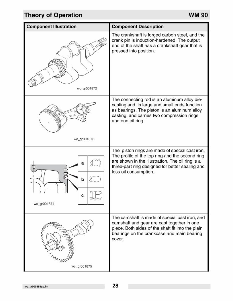
The crankshaft is forged carbon steel, and the crank pin is induction-hardened. The output end of the shaft has a crankshaft gear that is pressed into position.
The connecting rod is an aluminum alloy die-casting and its large and small ends function as bearings. The piston is an aluminum alloy casting, and carries two compression rings and one oil ring.
The piston rings are made of special cast iron. The profile of the top ring and the second ring are shown in the illustration. The oil ring is a three-part ring designed for better sealing and less oil consumption.
The camshaft is made of special cast iron, and camshaft and gear are cast together in one piece. Both sides of the shaft fit into the plain bearings on the crankcase and main bearing cover.
Component Illustration Component Description
wc_gr001872
wc_gr001873
wc_gr001874
a
b
c
wc_gr001875
wc_tx000388gb.fm 28

WM 90 Theory of Operation
The intake valve is located on the flywheel side of the cylinder head. Hard alloy valve seats are molded in the cylinder head and satellite is fused to the exhaust valve face. The cylinder baffle leads cooling air to the exhaust valve area for optimum cooling.Reference: intake (a); exhaust (b).
The cylinder head is an aluminum die-casting which utilizes wedge-type combustion cham-ber for high combustion efficiency.
The governor is a centrifugal flyweight type which ensures constant operation at the selected speed during load variations. The governor gear (a) with governor weights is installed on the main bearing cover.
Component Illustration Component Description
wc_gr001876
IN EX
a b
wc_gr001877
wc_gr001878
a
wc_tx000388gb.fm 29

Theory of Operation WM 90
The large fins (a) on the flywheel provide suffi-cient cooling air capacity for the inlet and exhaust area and cylinder. The cylinder baffle directs the cooling air flow efficiently.
All the rotating and sliding parts are splash- lubricated by the oil splasher (a) on the con-necting rod.
The ignition system is a transistor-controlled magneto system which consists of a flywheel (a) and an ignition coil (b) with a built-in tran-sistor mounted on the crankcase. This system has an automatic ignition timing advance sys-tem for easy starting.
Component Illustration Component Description
wc_gr001949
a
wc_gr001879
a
wc_gr001880
a
b
wc_tx000388gb.fm 30

WM 90 Theory of Operation
WM 90 engines use a diaphragm-type carbu-retor.
The air cleaner is a heavy-duty three-stage type with cyclonic precleaner.
An automatic decompression mechanism (a), that opens the exhaust valve before the piston reaches maximum compression, is assembled on the camshaft for easy starting. During engine operation the decompression system is overpowered by centrifugal force and com-pression is fully utilized to produce power.
Component Illustration Component Description
wc_gr001881
wc_gr002032
wc_gr001883
a
wc_tx000388gb.fm 31

Theory of Operation WM 90
4.7 Cross Section Across Shaft
wc_gr001884
2
3
7
88
99
10
11
12
13
1
1
wc_tx000388gb.fm 32

WM 90 Theory of Operation
4.8 Cross Section Across Shaft Components
See Graphic: wc_gr001884.
Ref Description Ref Description
1 Cylinder head 9 Main bearing cover
2 Piston pin 10 PTO shaft
3 Ignition coil 11 Piston ring
4 Blower housing 12 Piston
5 Recoil starter 13 Muffler
6 Flywheel 14 Exhaust valve
7 Crankcase 15 Intake valve
8 Flange adapter
wc_tx000388gb.fm 33

Theory of Operation WM 90
4.9 Cross Section Along Shaft
1
4
10
14
g
wc_tx000388gb.fm 34

WM 90 Theory of Operation
4.10 Cross Section Along Shaft Components
See Graphic: wc_gr001885
.
Ref Description Ref Description
1 Push rod 9 Stiffener
2 Carburetor 10 Plug
3 Air cleaner 11 Oil gauge
4 Tappet 12 Connecting rod
5 Camshaft 13 Spark plug
6 Governor lever 14 Rocker arm
7 Speed control lever 15 Rocker cover
8 Crankshaft
wc_tx000388gb.fm 35
Maintenance WM 90 Repair
5. Maintenance
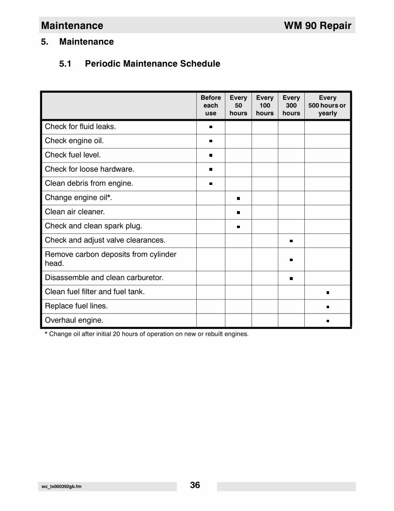
5.1 Periodic Maintenance Schedule
Beforeeachuse
Every 50
hours
Every100
hours
Every300
hours
Every500 hours or
yearly
Check for fluid leaks. �
Check engine oil. �
Check fuel level. �
Check for loose hardware. �
Clean debris from engine. �
Change engine oil*. �
Clean air cleaner. �
Check and clean spark plug. �
Check and adjust valve clearances. �
Remove carbon deposits from cylinder head.
�
Disassemble and clean carburetor. �
Clean fuel filter and fuel tank. �
Replace fuel lines. �
Overhaul engine. �
* Change oil after initial 20 hours of operation on new or rebuilt engines.
wc_tx000392gb.fm 36

WM 90 Repair Maintenance
5.2 Servicing Air Cleaner
See Graphic: wc_gr001306
NEVER use gasoline or other types of low flash point solvents forcleaning the air filter. A fire or explosion could result.
NOTICE: NEVER run the engine without the main paper air filter (b).Severe engine damage will occur.
Clean elements using the following procedure:
5.2.1 Remove the air cleaner cover (a). Remove the main paper filterelement (b) and secondary prefilter (c) and inspect them for holes ortears. Replace the elements if they are damaged.
5.2.2 Main paper filter element (b): Replace the main paper filter element ifit appears heavily soiled.
5.2.3 Prefilter (c): Clean the prefilter with low-pressure compressed air.When very soiled, wash the prefilter in a solution of mild detergent andwarm water. Rinse it thoroughly in clean water. Allow the prefilter to drythoroughly before reinstalling.
Note: Do not oil the prefilter.
5.2.4 Wipe out the filter housing (d) with a clean cloth. Do not usecompressed air.
NOTICE: Do not allow dirt to get into the engine intake port (k) whilecleaning. Damage to engine will result.
5.2.5 Check that the precleaner debris ejector slot (i) is clear.
WARNING
wc_gr001306
a
b
c
d
k
i
wc_tx000392gb.fm 37

Maintenance WM 90 Repair
5.3 Servicing Fuel Filter and Fuel Tank
See Graphic: wc_gr002017
5.3.1 Drain fuel tank completely.
5.3.2 Remove fuel line from fuel flow valve (a).
5.3.3 Unscrew fuel filter assembly (b) from tank.
5.3.4 Clean filter with parts cleaning solvent.
5.3.5 Inspect gasket (c) and filter for damage and replace them if necessary.
5.3.6 Clean sediment from inside of fuel tank.
5.3.7 Re-install gasket, fuel filter, valve, and fuel lines.
wc_gr002017
b
a
c
wc_tx000392gb.fm 38

WM 90 Repair Maintenance
5.4 Long-Term Storage
5.4.1 Drain the fuel from the tank.
5.4.2 Start the engine and run it until remaining fuel is used.
5.4.3 Remove the spark plug. Pour approximately 30 ml (1 oz.) of clean SAE10W30 engine oil into the cylinder through the spark plug opening.
5.4.4 Pull the starter rope slowly to distribute oil in the engine.
5.4.5 Re-install the spark plug.
wc_tx000392gb.fm 39
Dissassembly/Reassembly General Information WM 90 Repair
6. Dissassembly/Reassembly General Information
6.1 Tools
Because all possible problems encountered while repairing themachine cannot be anticipated, it is up to the mechanic to use commonsense and good judgement in tool selection.
The use of any special tools is recommended only for those operationswhere the use of conventional tools proves inadequate.
Before substituting another tool or procedure, you should be satisfiedthat neither personal injury nor damage to the component will result.
6.2 Ordering Parts
The repair procedures contained in this manual do not include partnumbers. For parts replacement information, refer to the Parts Bookoriginally supplied with the machine.
If the original Parts Book has been lost, a replacement may be orderedfrom Wacker Corporation. When ordering a replacement Parts Book,please list the model number, item number, revision level, and serialnumber of the machine. Parts Books are also available on the WackerCorporation Web site. See www.wackergroup.com. Enter the site as avisitor.
6.3 Reference Numbers ( )
Repair procedures contain reference numbers enclosed inparentheses ( ). These numbers refer to the item numbers shown onthe assembly drawings and other detailed drawings. They are includedto aid the mechanic in identifying parts and assembling components.
6.4 Weight Block
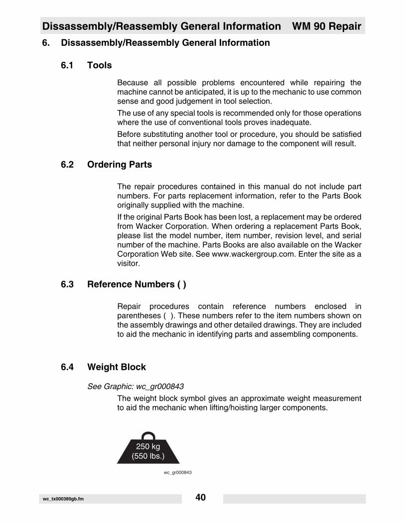
See Graphic: wc_gr000843
The weight block symbol gives an approximate weight measurementto aid the mechanic when lifting/hoisting larger components.
250 kg(550 lbs.)
wc_gr000843
wc_tx000389gb.fm 40

WM 90 Repair Disassembly Procedures
7. Disassembly Procedures
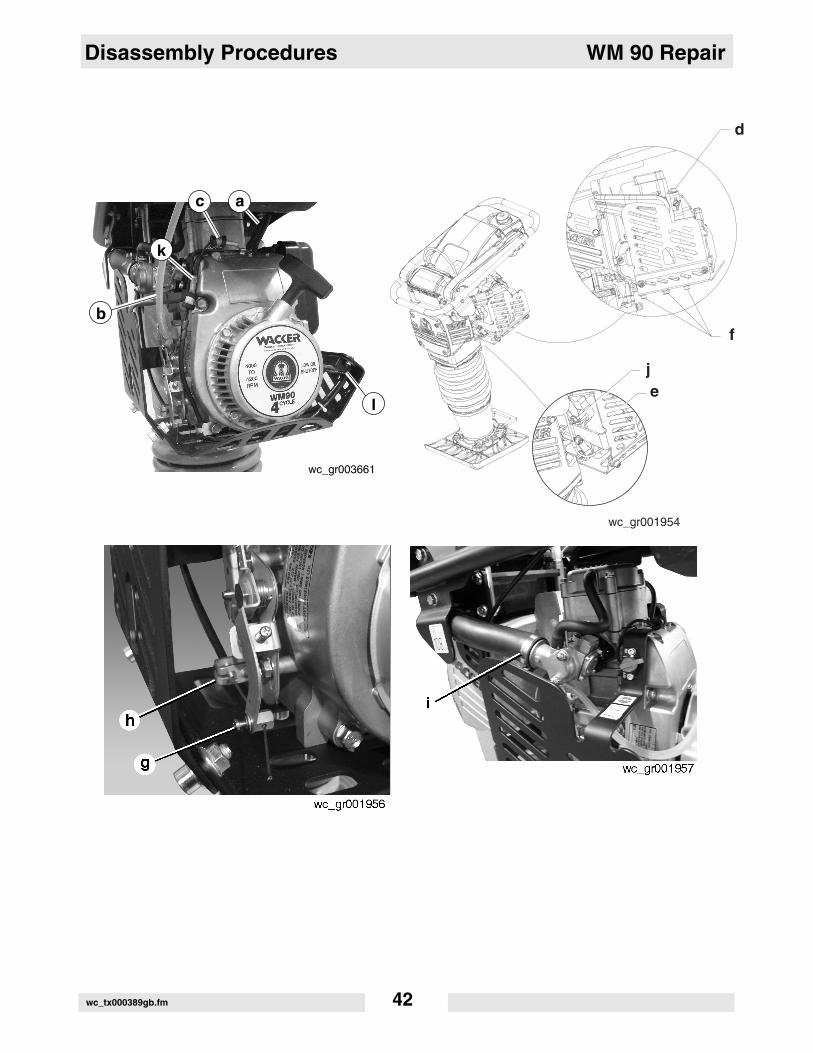
7.1 Removing Engine from Rammer
See Graphic: wc_gr001954, wc_gr003661, wc_gr001956, and wc_gr001957
7.1.1 Disconnect the spark plug cap (a) from the spark plug.
7.1.2 Disconnect the fuel line (b) from the carburetor and plug the line.
7.1.3 Disconnect the stop switch wire (c).
7.1.4 Disconnect the wiring (k) from the low-oil unit (l) (if equipped).
7.1.5 Remove the M8 x 16 bolt and washer (d) securing the guard to theengine.
7.1.6 Remove the M8 bolt and washer (e) securing the guard to the rammercrankcase.
7.1.7 Remove the six M8 bolts (f) securing the lower guard to the engine andremove the guard.
7.1.8 Remove the wire running from the engine to the low-oil unit (ifequipped).
7.1.9 Loosen the retainer (g) from the throttle cable. Pry open the clamp (h)and remove the throttle cable.
7.1.10 Loosen the clamp (i) securing the air intake hose to the carburetor andremove the hose.
7.1.11 Remove the four nuts (j) securing the engine to the adapter andremove the heat shield and the engine.
wc_tx000389gb.fm 41
Disassembly Procedures WM 90 Repair
d
ej
f
wc_gr001954
b
l
ac
k
wc_gr003661
wc_tx000389gb.fm 42

WM 90 Repair Disassembly Procedures
7.2 Draining Oil
See Graphic: wc_gr001886
Note: In the interests of environmental protection, place plasticsheeting and a container under the machine to collect the liquid whichdrains off. Dispose of this liquid properly.
7.2.1 Remove the drain plug (a) and gasket (b).
7.2.2 Remove oil gauge (c) and gasket (d).
7.2.3 Drain oil from crankcase. Replace plug, oil gauge, and gaskets whencomplete.
wc_gr001886
c
d
a
b
wc_tx000389gb.fm 43

Disassembly Procedures WM 90 Repair
7.3 Removing Recoil Starter and Blower Housing
See Graphic: wc_gr003650
7.3.1 Remove the bolts (a) and remove the recoil starter (b) from thehousing.
7.3.2 Remove the flange bolts (f), cap screw (g), and remove the blowerhousing (h).
wc_gr003650
a
b
h
f
g
wc_tx000389gb.fm 44

WM 90 Repair Disassembly Procedures
7.4 Removing Muffler
See Graphic: wc_gr001888
7.4.1 Remove the flange nuts (a).
7.4.2 Remove the flange bolts (b).
7.4.3 Remove the bolts and washers (c) and remove the muffler (d) and thegasket (e).
wc_tx000389gb.fm 45

Disassembly Procedures WM 90 Repair
7.5 Removing Governor Lever, Carburetor, Speed Control Lever
See Graphic: wc_gr001890
7.5.1 Mark the hole in which the governor spring (a) is attached and removethe spring.
7.5.2 Loosen the M6 bolt (b) and remove the governor lever (c).
7.5.3 Remove the governor rod (d) and the rod spring (e), and if necessary,bushing (f).
7.5.4 Remove the carburetor flange (g), the gaskets (h), the carburetor (i).
7.5.5 Remove the bolts (j) securing the insulator (k) and remove theinsulator and gasket (m).
7.5.6 Remove the M6 pivot bolt (n) and washer (o) and remove the speedcontrol lever (p).
7.5.7 Also remove return spring (q) and spacer (r).
7.5.8 Remove the two M6 x 8 flange bolts (s) and remove the base plate (t).
wc_tx000389gb.fm 46
WM 90 Repair Disassembly Procedures
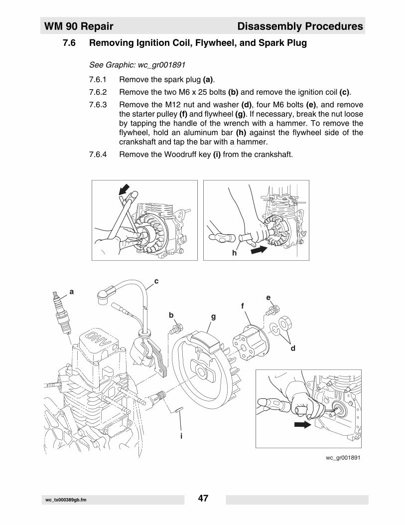
7.6 Removing Ignition Coil, Flywheel, and Spark Plug
See Graphic: wc_gr001891
7.6.1 Remove the spark plug (a).
7.6.2 Remove the two M6 x 25 bolts (b) and remove the ignition coil (c).
7.6.3 Remove the M12 nut and washer (d), four M6 bolts (e), and removethe starter pulley (f) and flywheel (g). If necessary, break the nut looseby tapping the handle of the wrench with a hammer. To remove theflywheel, hold an aluminum bar (h) against the flywheel side of thecrankshaft and tap the bar with a hammer.
7.6.4 Remove the Woodruff key (i) from the crankshaft.
wc_gr001891
ac
b
d
e
g
h
f
i
wc_tx000389gb.fm 47

Disassembly Procedures WM 90 Repair
7.7 Removing Rocker Cover and Cylinder Head
See Graphic: wc_gr001892
7.7.1 Remove the four M6 x 60 bolts (a) and remove the rocker cover (b) andgasket (c).
7.7.2 Remove the breather (d), gaskets (e), and spacer (f).
7.7.3 Remove the two M8 x 55 bolts (g) and the two M8 bolts (h), removethe cylinder head (k) and gasket (l)
7.7.4 Remove the pipes (m) and push rods (n).
7.7.5 If necessary, remove the seal (i) and the guide (j).
wc_tx000389gb.fm 48

WM 90 Repair Disassembly Procedures
7.8 Removing Bearing Cover
See Graphic: wc_gr001893
7.8.1 Remove the nine M6 x 30 bolts and washers (a) and remove the mainbearing cover (b).
Note: If necessary, use a rubber mallet (c) and tap the cover to loosenit from the crankcase.
wc_gr001893
ba
c
wc_tx000389gb.fm 49

Disassembly Procedures WM 90 Repair
7.9 Removing Camshaft and Tappets
See Graphic: wc_gr001894
7.9.1 Lay crankcase on the flywheel side and push the tappets (a) into thecrankcase and remove the camshaft (b).
a
bb
wc_gr001894
wc_tx000389gb.fm 50

WM 90 Repair Disassembly Procedures
7.10 Removing Connecting Rod and Piston
See Graphic: wc_gr001895
7.10.1 Remove connecting rod bolts (a) and connecting rod cap (b).
7.10.2 Turn crankshaft until piston (c) comes to top dead center, push outconnecting rod (d) and piston assembly through top of cylinder.
Note: Scrape off all carbon deposits that might interfere with removalof piston from upper end of cylinder.
7.10.3 Remove the clips (e) and the piston pin (f) to remove connecting rodfrom piston.
7.10.4 Being careful not to damage the rings or piston, remove the rings (g)from the piston by spreading them at the gap and pulling them from thepiston.
a
b
c
e
e
f
g
d
wc_gr001895
wc_tx000389gb.fm 51

Disassembly Procedures WM 90 Repair
7.11 Removing Crankshaft
See Graphic: wc_gr001896
7.11.1 To remove the crankshaft (a), tap lightly on flywheel end of thecrankshaft with a rubber mallet (b).
a
b
wc_gr001896
wc_tx000389gb.fm 52
WM 90 Repair Disassembly Procedures
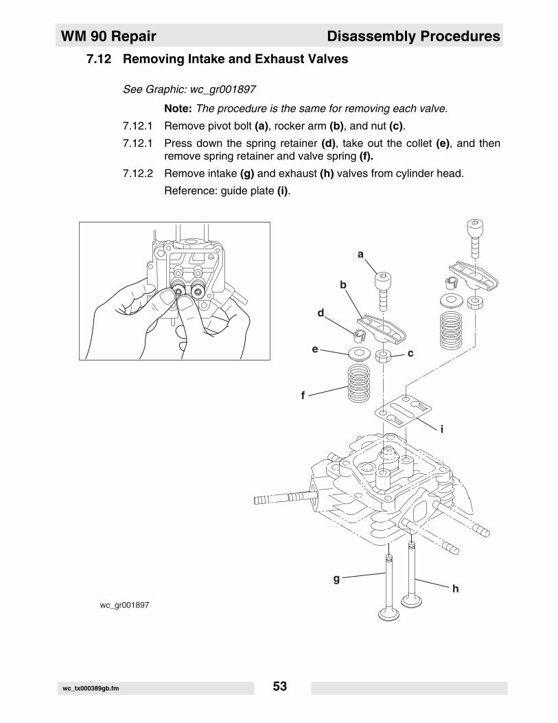
7.12 Removing Intake and Exhaust Valves
See Graphic: wc_gr001897
Note: The procedure is the same for removing each valve.
7.12.1 Remove pivot bolt (a), rocker arm (b), and nut (c).
7.12.1 Press down the spring retainer (d), take out the collet (e), and thenremove spring retainer and valve spring (f).
7.12.2 Remove intake (g) and exhaust (h) valves from cylinder head.
Reference: guide plate (i).
wc_gr001897
b
c
d
e
f
a
gh
i
wc_tx000389gb.fm 53

Reassembly Procedures WM 90 Repair
8. Reassembly Procedures
8.1 Notes on Reassembly
Observe the following prior to/during reassembly of the engine:
• Clean each part carefully, taking special care with the piston, cylinder, crankshaft, connecting rod, and bearings.
• Scrape off any carbon deposits on the cylinder head and the piston head. Be particularly careful when removing carbon from the piston ring grooves.
• Inspect oil seals for any damage to the lip. Replace them if damaged. Apply oil to lip before re-assembling.
• Replace all gaskets with new ones.
• Replace keys, pins, bolts and nuts with new ones if necessary.
• Tighten nuts and bolts to the specified torque settings.
• During re-assembly, apply oil to all moving parts.
• Check clearances and end plays. Adjust the clearances as necessary.
• When mounting any major moving part, rotate it with your hand to check for any jamming or abnormal noise.
8.2 Crankshaft
See Graphic: wc_gr001898
8.2.1 Wrap the keyway portion of the crankshaft (a) with polyvinyl tape (b)and insert the crankshaft into the crankcase, taking care not to damagethe oil seal lip.
wc_gr001898
b
a
wc_tx000389gb.fm 54
WM 90 Repair Reassembly Procedures
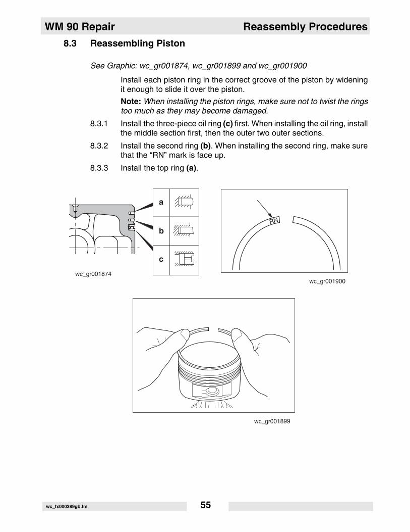
8.3 Reassembling Piston
See Graphic: wc_gr001874, wc_gr001899 and wc_gr001900
Install each piston ring in the correct groove of the piston by wideningit enough to slide it over the piston.
Note: When installing the piston rings, make sure not to twist the ringstoo much as they may become damaged.
8.3.1 Install the three-piece oil ring (c) first. When installing the oil ring, installthe middle section first, then the outer two outer sections.
8.3.2 Install the second ring (b). When installing the second ring, make surethat the “RN” mark is face up.
8.3.3 Install the top ring (a).
wc_gr001874
a
b
c
wc_gr001899
wc_gr001900
wc_tx000389gb.fm 55

Reassembly Procedures WM 90 Repair
8.4 Reassembling Piston and Connecting Rod
See Graphic: wc_gr001901
8.4.1 Install the piston (a) onto the connecting rod (b) using the piston pin (c)and two clips (d).
d
d
a
c
b
wc_gr001901
wc_tx000389gb.fm 56

WM 90 Repair Reassembly Procedures
8.5 Installing Piston
See Graphic: wc_001902, wc_gr001903, and wc_gr001904
8.5.1 Position the piston rings so that the gaps in the rings are at 90°intervals from each other (a = top ring, b = second ring, c = oil ring).
8.5.2 Apply oil to the piston rings, the cylinder bore, and the large end of theconnecting rod.
8.5.3 Position the “MA” mark on the crankshaft so that it faces the flywheelside of the engine when assembled. Then, using a ring guide (d), holdthe piston rings in and lower the piston into the cylinder.
Note: If you do not have a ring guide, hold the piston rings in with yourfingers while tapping lightly on the piston head with a block of wood orrubber mallet.
8.5.4 Rotate the crankshaft down to the bottom dead center and lightly tapthe piston head until the large end of the connecting rod touches thecrank pin.
8.5.5 To mount the connecting rod, line up the matching marks (e) and fit theconnecting rod cap to the connecting rod. Secure the two halvestogether using two M5 bolts. Torque bolts to: 5.9–7.8 Nm (4.3–5.7ft.lbs).
8.5.6 Check for free movement of the connecting rod by turning thecrankshaft slowly.
"MA"
d
wc_gr001902
wc_gr001904
e
wc_tx000389gb.fm 57

Reassembly Procedures WM 90 Repair
8.6 Installing Tappets and Camshaft
See Graphic: wc_gr001905
8.6.1 Oil the tappets (a) and install them. Push them in fully to avoid damageduring camshaft (b) installation.
8.6.2 Remove spacer (c) to allow viewing of timing mark.
8.6.3 Lubricate the bearing surfaces of camshaft. Align the timing marks (d)on the camshaft with the timing marks on the crankshaft and install thecamshaft into the crankcase.
NOTICE: Incorrect valve timing will cause malfunction of the engine.
wc_gr001905
a
c
b
d
wc_tx000389gb.fm 58

WM 90 Repair Reassembly Procedures
8.7 Adjusting Crankshaft End Play
See Graphic: wc_gr001906
Adjust the end play to 0.2 mm (0.008 in.) using the proper spacer.Determine the proper spacer in the following manner:
8.7.1 Measure the height “A”. Distance from main bearing cover matingsurface (a) to the inner race of the ball bearing (b).
8.7.2 Measure the depth “B”. Distance from the crankcase mating surface(c) to the crankshaft gear (d).
B-A = side clearance
Side clearance - 0.2 mm (0.008 in.) = thickness of crankshaft shim.
Spacer shims are available in the following thicknesses:
0.6 mm (0.024 in.)
0.8 mm (0.031 in.)
1.0 mm (0.039 in.)
8.7.3 Reference: crankcase (e); crankshaft (f); depth gauge (g).
wc_gr001906
b af
g
e
cd
d
wc_tx000389gb.fm 59

Reassembly Procedures WM 90 Repair
8.8 Installing Main Bearing Cover
See Graphic: wc_gr001907
8.8.1 Lubricate the oil seal and bearing surfaces with engine oil.
8.8.2 Coat the mating surfaces of the main bearing cover (a) and crankcase(b) with Loctite® 515 Gasket Eliminator or equivalent.
8.8.3 Using nine M6 x 30 bolts and washers (c) secure the main bearingcover to the crankcase. Tighten bolts in pattern shown on illustration.Torque the bolts to: 9.8–11.8 Nm (7.2–8.7 ft.lbs.).
wc_gr001907
b
ac
1
2
3
4
8
9
5
6
7
wc_tx000389gb.fm 60

WM 90 Repair Reassembly Procedures
8.9 Cylinder Head
8.9.1 Clean carbon and gum deposits from the valves, seats, ports, andguides. Inspect them once clean. Replace valves that are badlyburned, pitted, or warped.
8.9.2 When installing valves in cylinder head, oil the valve stems and insertthem into valve guide. Then place cylinder head on a flat table, installspring and spring retainer.
8.9.3 Valve guides should be replaced when valve stem clearance exceedsspecifications. See Clearance Data and Limits Table.
8.9.4 Draw valve guides out and press new guides in. See Clearance Dataand Limits Table.
8.9.5 After replacing valves and guides, lap valves in place until a uniformring shows around the face of the valve. Clean valves and washcylinder head thoroughly.
8.9.6 Install cylinder head onto cylinder with new head gasket. Tighten thefour M8 x 55 flange bolts in a crisscross pattern, in three incrementalsteps using the following torque values:
Step 1: 5.0 Nm (3.6 ft.lbs.)Step 2: 9.8 Nm (7.2 ft.lbs.)Step 3: 18.6–20.6 Nm (13.7–15.2 ft.lbs.)
wc_tx000389gb.fm 61

Reassembly Procedures WM 90 Repair
8.10 Reassembling Rocker Arms and Push Rods
See Graphic: wc_gr001908
8.10.1 Insert push rods (a) into crankcase. Place push rod tip into the hollowof the tappet top.
NOTICE: An oil return slot is located next to the tappet boss. If you donot put the push rod in the tappet properly, the push rods will fall intothe crankcase. If this happens, removal of the main bearing cover willbe necessary to remove them.
8.10.2 Place the gasket (b) on the crankcase. Position the intake valve (c)and the exhaust valve (d) into the cylinder head (e). Using four M8 x55 flange bolts (f), secure the cylinder head to the crankcase .
8.10.3 Position the guide plate (g). Insert the valve spring (h), the springretainer (i), and secure them to the valve using the collet (j). Completefor both intake and exhaust.
8.10.4 Using the pivot bolt (l) and the M6 nut (m), install the rocker arm (k).Complete for both intake and exhaust.
wc_gr001908
a
b
d
f
c
e
k
m
l
hg
i
j
wc_tx000389gb.fm 62

WM 90 Repair Reassembly Procedures
8.11 Adjusting Valve Clearances
See Graphic: wc_gr001909 and wc_gr001910
Note: Check and adjust valve clearances when engine is cold.
8.11.1 Temporarily fit the flywheel in position.
8.11.2 Position the piston at the top dead center of the compression stroke bymatching the alignment mark on the flywheel (a) with the alignmentmark on the crankcase (b).
8.11.3 Loosen the nut (c) under the rocker arm. Position a feeler gauge (e)as shown and turn the pivot bolt (d) until the clearance measures 0.07–0.13 mm (0.0028–0.0051 in.). Tighten pivot bolt. Complete for bothintake and exhaust valves.
8.11.4 Check operation of the valves by turning the crankshaft. Recheck thevalve clearances.
wc_gr001910
c
d
e
wc_gr001909
a
b
wc_tx000389gb.fm 63

Reassembly Procedures WM 90 Repair
8.12 Installing Rocker Cover and Spark Plug
See Graphic: wc_gr001911
Note: Replace the gasket with a new one each time the rocker coveris removed.
8.12.1 Using four M6 bolts (a), secure the rocker cover (b) and gasket (c) tothe cylinder head.
8.12.2 Remove any carbon deposits from the spark plug and inspect theelectrode for damage. Replace the spark plug if necessary. Use NGKBM6A or BMR6A
Electrode gap: 0.6–0.7 mm (0.23–0.27 in.).
Spark Plug Torque:
New plug: 11.8–14.7 Nm (8.7–10.9 ft.lbs.)Reused plug: 22.6–24.5 Nm (16.6–18.1 ft.lbs.)
wc_tx000389gb.fm 64

WM 90 Repair Reassembly Procedures
8.13 Installing Flywheel Magneto
8.13.1 Place the Woodruff key in the keyway of the crankshaft. Thoroughlywipe off oil and grease from the tapered portion of the crankshaft andalso from the flywheel center hole.
8.13.2 Install the flywheel, M12 nut and washer to the crankshaft. Hold theflywheel using a strap wrench and torque the nut to 44.2–49.1 Nm(32.5–36.2 ft.lbs.).
8.14 Installing Ignition Coil
See Graphic: wc_gr001913
8.14.1 Using two M6 x 25 bolts and washers, mount the ignition coil (a) to theengine. Before tightening the bolts, adjust the air gap using a thicknessgauge (b). Adjust the air gap to 0.3–0.5 mm (0.012–0.020 in.).
wc_gr001913
ab
wc_tx000389gb.fm 65

Reassembly Procedures WM 90 Repair
8.15 Installing Governor, Speed Control System, and Carburetor
See Graphic: wc_gr001890
8.15.1 Install governor lever (a) to governor shaft, then tighten the locking bolt(b) temporarily.
8.15.2 Install baseplate (t) to crankcase using two M6 x 8 flange bolts (s).
8.15.3 Install the speed control lever (p), friction washer (o), pivot bolt (n),spacer (r) and return spring (q).
8.15.4 Attach the governor spring (c) to proper holes (as marked duringdisassembly) of governor lever and speed control lever.
8.15.5 Using bolts (j), install insulator (k) and gasket (m).
8.15.6 Install carburetor (i) and gaskets (h) to cylinder head. Also installappropriate carburetor flange (g).
8.15.7 Install bushing (f). Install governor rod (d) to governor lever and throttlelever of carburetor. Attach spring (e) over governor rod.
8.15.8 See section Adjusting Governor System.
a
b
cd
e
f
gh
i
j
k
po
q
t
s
r
n
wc_gr001890
m
wc_tx000389gb.fm 66

WM 90 Repair Reassembly Procedures
8.16 Adjusting Governor System
See Graphic: wc_gr001914
8.16.1 Turn the speed control lever (a) all the way toward the high speedposition and secure it by tightening the self-locking screw.
8.16.2 Check that the governor lever (b) is pulled by the governor spring (c)and carburetor throttle valve is fully open.
8.16.3 Turn the governor shaft (d) clockwise all the way using a screw driver,and tighten the lock bolt to secure the lever on the shaft.
8.16.4 Loosen the lock nut to allow the speed control lever to move freely.
Reference: governor rod spring (e); normal hooking position ofgovernor spring (f).
8.17 Installing Muffler
See Graphic: wc_gr001888
8.17.1 Using two flange nuts (a), two flange bolts (b), and bolts and washers(c), install muffler (d) and gasket (e).
wc_gr001914
ab
e
f
c
d
wc_tx000389gb.fm 67
Reassembly Procedures WM 90 Repair
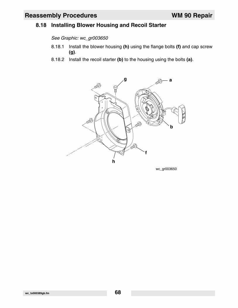
8.18 Installing Blower Housing and Recoil Starter
See Graphic: wc_gr003650
8.18.1 Install the blower housing (h) using the flange bolts (f) and cap screw(g).
8.18.2 Install the recoil starter (b) to the housing using the bolts (a).
wc_gr003650
a
b
h
f
g
wc_tx000389gb.fm 68

WM 90 Repair Reassembly Procedures
8.19 Re-installing Engine
See Graphic: wc_gr001954, wc_gr003661, wc_gr001956, and wc_gr001957
8.19.1 Position the engine so that mounting studs protrude from the adapterplate mounted to the rammer crankcase. Position heatshield andsecure engine and heatshield to rammer with four nuts (j).
8.19.2 Connect the wire from the low-oil unit (l) (if equipped) to the engine.
8.19.3 Using six M8 bolts (f) mount the guards to the engine. Secure upperguard to engine using M8 x 16 bolt (d) and to rammer crankcase usingM8 bolt (e).
8.19.4 Secure the throttle cable to the engine by crimping clamp (h). Feedcable through retainer (g) and tighten screw.
8.19.5 Secure air intake hose to engine by crimping clamp (i).
8.19.6 Reconnect stop switch wire (c).
8.19.7 Connect the wiring (k) from the low-oil unit (l) (if equipped).
8.19.8 Reconnect fuel line (b) to the carburetor.
8.19.9 Reconnect spark plug (a).
wc_tx000389gb.fm 69

Reassembly Procedures WM 90 Repair
d
ej
f
wc_gr001954
b
l
ac
k
wc_gr003661
wc_tx000389gb.fm 70

WM 90 Repair Reassembly Procedures
8.20 Break-in Operation
A new engine or one that has been completely overhauled by beingfitted with a new piston, rings, valves, and connecting rod should bethoroughly run-in before being put into service.
Good bearing surfaces and running clearances between the variousparts can only be established by operating the engine under reducedspeed and loads for a short period of time.
Run-in the engine according to the schedule below. During the run-inperiod, check for oil leaks, make final carburetor adjustments, andregulate the engine operating speed.
Step Engine Load Speed (rpm) Duration (min.)
1 No load 2500 10
2 No load 3000 10
3 No load 3600 10
4 0.7 kW (1.0 hp) 3000 30
5 1.0 kW (1.9 hp) 3600 60
wc_tx000389gb.fm 71

Sub Systems WM 90 Repair
9. Sub Systems
9.1 Magneto
The ignition system of the WM 90 is a breakerless flywheel magnetowith an automatic advancing system.
This system has no breaker points and thus is free from the startingand running problems associated with dirty, burnt, or corroded breakerpoints.
The electronic automatic advancing ensures easy starts and highperformance at operating speed by advancing the ignition timing to themost suitable point.
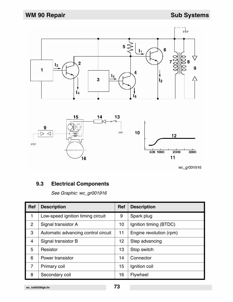
9.2 Engine Basic Electric Theory
See Graphic: wc_gr001916
9.2.1 Revolution of the flywheel generates electricity in the primary side ofthe ignition coil, and the base current I1 flows to the power transistor.
Current I1 turns the power transmitter “ON” and the electric current I2flows.
9.2.2 At lower engine revolution, when the flywheel reaches the ignitionpoint, the low speed ignition timing control circuit operates to run thebase current I3 to turn the signal transistor A “ON” allowing the currentI1 to bypass as current I4.At this moment, the power transistor turns “OFF” and the current I2 isabruptly shut off resulting in the high voltage generated in thesecondary coil which produces sparks at the spark plug.
9.2.3 At higher engine revolution, the advancing control circuit operates atthe ignition timing to run the base current I5 to turn the signal transistorB “ON” allowing the current I1 to bypass as current I6.
At this moment the power transistor turns “OFF” and the current I2 isabruptly shut off resulting in the high voltage generated in thesecondary coil which produces sparks at the spark plug.
The operating timing of the advancing control circuit advances inaccordance with the increase of engine speed resulting in theadvancing of the ignition timing shown in the chart.
wc_tx000390gb.fm 72
WM 90 Repair Sub Systems
9.3 Electrical Components
See Graphic: wc_gr001916
Ref Description Ref Description
1 Low-speed ignition timing circuit 9 Spark plug
2 Signal transistor A 10 Ignition timing (BTDC)
3 Automatic advancing control circuit 11 Engine revolution (rpm)
4 Signal transistor B 12 Step advancing
5 Resistor 13 Stop switch
6 Power transistor 14 Connector
7 Primary coil 15 Ignition coil
8 Secondary coil 16 Flywheel
wc_tx000390gb.fm 73
Sub Systems WM 90 Repair
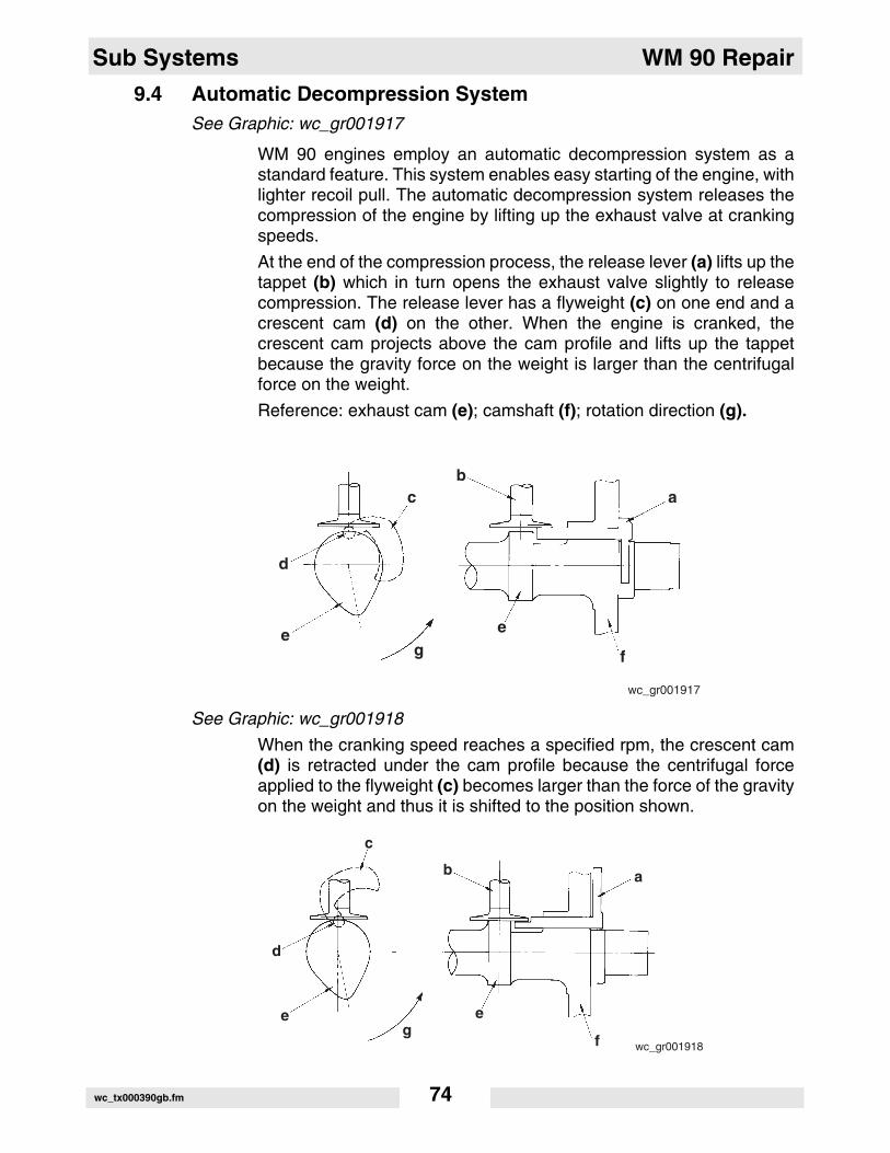
9.4 Automatic Decompression SystemSee Graphic: wc_gr001917
WM 90 engines employ an automatic decompression system as astandard feature. This system enables easy starting of the engine, withlighter recoil pull. The automatic decompression system releases thecompression of the engine by lifting up the exhaust valve at crankingspeeds.
At the end of the compression process, the release lever (a) lifts up thetappet (b) which in turn opens the exhaust valve slightly to releasecompression. The release lever has a flyweight (c) on one end and acrescent cam (d) on the other. When the engine is cranked, thecrescent cam projects above the cam profile and lifts up the tappetbecause the gravity force on the weight is larger than the centrifugalforce on the weight.
Reference: exhaust cam (e); camshaft (f); rotation direction (g).
See Graphic: wc_gr001918
When the cranking speed reaches a specified rpm, the crescent cam(d) is retracted under the cam profile because the centrifugal forceapplied to the flyweight (c) becomes larger than the force of the gravityon the weight and thus it is shifted to the position shown.
wc_gr001917
ab
c
d
e e
fg
wc_gr001918
ab
c
d
e e
fg
wc_tx000390gb.fm 74

WM 90 Repair Sub Systems
9.5 Diaphragm-Type Carburetor
See Graphic: wc_gr001919
Ref Description Comment
1 Engine impulse The alternating action of the positive pressure and neg-ative pressure inside the engine crankcase operates the fuel pump diaphragm.
2 Fuel pump diaphragm The fuel pump diaphragm undulates in response to the engine impulse and as a result, it feeds the fuel through the fuel pump.
3 Fuel inlet The fuel inlet is the opening through which fuel is drawn from the fuel tank.
4 Inlet valve The inlet valve opens when the diaphragm is submitted to the action of a negative pressure in response to the movement of the pump diaphragm and the inlet valve shuts when it is submitted to a positive pressure.
5 Outlet valve The outlet valve shuts when it is submitted to the action of a negative pressure and opens when submitted to a positive pressure.
6 Inlet screen The inlet screen filters the fuel that is drawn from the fuel tank to the carburetor.
7 Inlet needle valve The inlet needle valve controls the fuel that is fed from the fuel pump to the metering chamber.
8 Throttle valve The throttle valve controls the volume of air drawn into the engine, thereby changing the engine speed.
9 Air vent hole The air vent hole is open to the atmosphere, with the purpose of allowing smooth operation of the metering diaphragm.
10 Metering diaphragm The metering diaphragm has the function of operating the metering lever, which is pulled up by the variations in the negative pressure of the engine.
11 Metering lever The metering lever has the function of opening/closing the inlet valve by transmitting the movements of the metering diaphragm to that valve.
12 Metering lever spring The metering lever spring has the function of pushing up the metering lever, thereby shutting the needle valve when the engine is stopped and when the metering chamber is full of fuel.
wc_tx000390gb.fm 75

Sub Systems WM 90 Repair
13 Metering chamber The metering chamber is the fuel storage compartment that has the function of supplying fuel to the nozzle holes and other parts.
14 First idle hole The first idle hole is the only fuel supply hole that is available when the engine is idling.
15 Second and third idle holes
The second and third idle holes have the function of supplying fuel when the throttle is at an intermediate opening state between the idling state and the fully open state.
16 Idle needle The idle needle has the function of controlling the fuel when the engine is at idling speeds and when the throt-tle is at low speed position.
17 High-speed needle The high speed needle has the function of controlling the fuel when the engine is operating at high speed and when the throttle is at a high speed position.
18 Main nozzle The main nozzle is the hole through which fuel is ejected when the engine is operating at high speed and when the throttle is at a high speed position.
19 Venturi The venturi has the function of increasing the air flow ar the nozzle section, thereby improving the atomization of the fuel.
20 Choke valve The choke valve has the function of shutting the suction of air when the engine is started at a cold state, thereby securing the temporary supply of rich fuel/air mixture.
Ref Description Comment
wc_tx000390gb.fm 76

WM 90 Repair Sub Systems
9 12
11
7
17
20
6
45
2
19
18
3
18
15
14
16
13
10
wc_gr001919
wc_tx000390gb.fm 77

Sub Systems WM 90 Repair
9.6 Carburetor Disassembly Procedure
See Graphic: wc_gr001920
Prior to disassembling the carburetor, wash it with an appropriatecleaning solvent.
9.6.1 Loosen the pump cover screw (14) and remove the screw and thepump cover (13).
9.6.2 Remove the pump gasket (12) and the diaphragm (11).
9.6.3 Place the carburetor with the metering side up and remove themetering cover screws (8).
9.6.4 Remove the metering cover (7), the diaphragm assembly (6), and thegasket (5).
9.6.5 Loosen the metering lever pin screw (17) and remove the lever (4), pin(18), spring (3), and needle valve (2).
wc_gr001920
13
12
14
11
1
19
218
17
16
87
6
5
43
910
15 20
wc_tx000390gb.fm 78

WM 90 Repair Sub Systems
9.7 Carburetor Inspection
See Graphic: wc_gr001920
9.7.1 Clean the carburetor and components with an appropriate solvent.
9.7.2 Check the gaskets for any deformation and/or damage. Replace anydeformed or damaged gaskets.
9.7.3 Make sure that the pump diaphragm (11) is not damaged. Also makesure that the inlet valve and outlet valve are flat and not bent.
9.7.4 Make sure that the metering diaphragm (6) is not damaged and thatthe plate is not bent.
9.7.5 Check the throttle shaft (19) and the choke shaft (20) for smoothoperation.
9.7.6 Check the inlet screen (1) for dirt. If the screen is dirty, wash it and blowit out with compressed air.
9.7.7 Check the inlet valve for abnormal wearing. If the inlet valve is worn,replace it.
9.8 Carburetor Reassembly
See Graphic: wc_gr001920
9.8.1 Mount the inlet screen (1) to the carburetor body.
9.8.2 Mount the inlet needle (2), metering lever spring (3), metering lever (4),and other related components.
9.8.3 Mount, in this order, the metering gasket (5), metering diaphragm, (6),and cover (7). Tighten the four cover screws.
9.8.4 Next, mount in this order, the pump diaphragm (11), pump gasket (12),and pump cover (13). Tighten the pump cover screw.
wc_tx000390gb.fm 79

Sub Systems WM 90 Repair
9.9 Carburetor Adjustments
See Graphic: wc_gr001920
Idling Adjustment:
9.9.1 Start the engine and adjust the idle adjust screw (15) so that the engineis running at a speed slightly lower than the speed at which the clutchengages.
High-Speed Adjustment:
9.9.2 Set the throttle valve (16) to the fully open position and check whetherthe engine rotates at the maximum engine speed as listed in theTechnical Data section.
wc_gr001920
13
12
14
11
1
19
218
17
16
87
6
5
43
910
15 20
wc_tx000390gb.fm 80

WM 90 Repair Recoil Starter
10. Recoil Starter
10.1 Recoil Starter Disassembly
See Graphic: wc_gr001830
Wear eye protection when working on the recoil starter.
To release the reel spring power:
10.1.1 Hold the starter knob and pull out the starter rope.
10.1.2 Pull out the rope fully and align the rope knot in the reel with the ropeguide.
10.1.3 Hold the reel down firmly with both thumbs, taking care to not allow itto spring back.
Note: The following procedure requires the help of an assistant.
10.1.4 Remove the knot from the reel, untie the knot and pull the rope outtoward the starter knob.
10.1.5 While controlling the reel with your thumbs, slowly wind it back as faras it will go.
Note: When the rope is pulled out to its full length, the force stored inthe spring reaches its maximum. Take care when handling the reel.
For machines with item numbers 0009386 rev. 111 and lower; 0009340 rev. 111 and lower; 0620051 rev. 107 and lower
CAUTION
wc_tx000627gb.fm 81

Recoil Starter WM 90 Repair
See Graphic: wc_gr001831To remove the components:
10.1.6 Grip the case (a) and loosen the set screw (b).
10.1.7 Remove, in this order: the set screw, the ratchet guide (c), the frictionspring (d), and the ratchet (e).
See Graphic: wc_gr001831
Remove the reel:
10.1.8 Hold down the reel (f) gently, to keep it from escaping from its case,and rotate it slowly back and forth by quarter turns until it movessmoothly.
10.1.9 Lift the reel up slightly and remove it from the case.
10.1.10 If the spring is about to pop out of the reel, repeat the previous twosteps.
Note: Since the spring is stored in the reel, make sure not to drop orshake the reel after removing it. Place it on a flat secure surface suchas a table.
wc_tx000627gb.fm 82
WM 90 Repair Recoil Starter
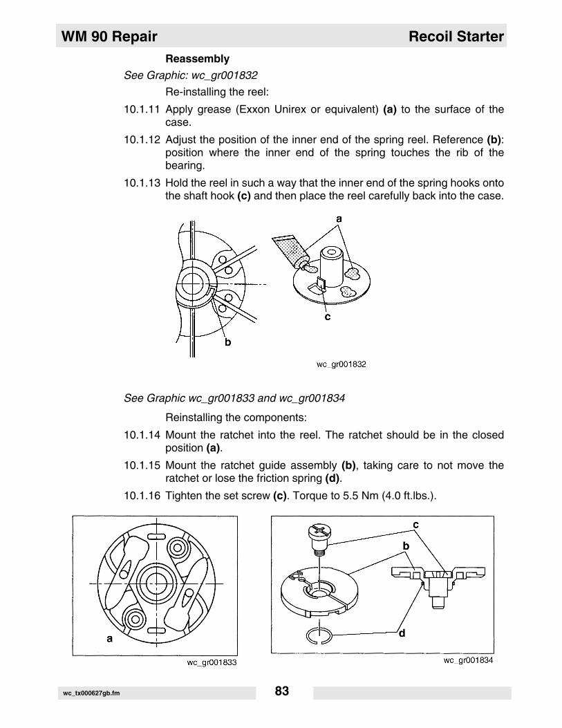
ReassemblySee Graphic: wc_gr001832
Re-installing the reel:
10.1.11 Apply grease (Exxon Unirex or equivalent) (a) to the surface of thecase.
10.1.12 Adjust the position of the inner end of the spring reel. Reference (b):position where the inner end of the spring touches the rib of thebearing.
10.1.13 Hold the reel in such a way that the inner end of the spring hooks ontothe shaft hook (c) and then place the reel carefully back into the case.
See Graphic wc_gr001833 and wc_gr001834
Reinstalling the components:
10.1.14 Mount the ratchet into the reel. The ratchet should be in the closedposition (a).
10.1.15 Mount the ratchet guide assembly (b), taking care to not move theratchet or lose the friction spring (d).
10.1.16 Tighten the set screw (c). Torque to 5.5 Nm (4.0 ft.lbs.).
wc_tx000627gb.fm 83

Recoil Starter WM 90 Repair
See Graphic: wc_gr001835Tensioning the reel spring:
10.1.17 Grip the case and turn the reel 6 times counterclockwise.
10.1.18 Rotate the reel so that the rope hole (a) is aligned with the rope guide(b).
See Graphic: wc_gr001836 and wc_gr001837
Installing the rope:
Note: This procedure requires help from an assistant.
10.1.19 Pass the rope through the rope guide and the rope hole of the reel andpull through approximately 20 cm (7-3/4 in.) out of the reel.
10.1.20 Tie a knot in the end of the rope.
10.1.21 Put the rope into the reel, taking care that the rope end does not stickup.
10.1.22 Grasp the rope firmly with one hand approximately 50 cm (19-5/8 in.)from the rope guide and keep the rope tense, taking care that the ropeis not pulled into the reel.
10.1.23 Release the reel carefully and allow the rope to be wound back slowlyby the force of the spring until the knob reaches the rope guide.
wc_tx000627gb.fm 84

WM 90 Repair Recoil Starter
10.2 Checking the Recoil Starter After Reassembly
Note: Carry out the following procedures to ensure proper operation ofthe starter assembly.
10.2.1 Pull the starter rope 2–3 times.
• If the starter knob is too heavy to pull, check that each part has been assembled as specified.
• If the ratchet does not work, check for missing parts such as the fric-tion spring.
10.2.2 Pull out the starter knob as far as it will go.
• If the starter rope remains in the rope slot in the reel, the spring may be over-stressed. To fix this, pull out the starter rope approximately 30 cm (11-3/4"), and controlling the rotation of the reel with your thumb, allow the starter rope to rewind about one or two turns.
• If the starter rope rewinds slowly or only partially, apply grease or oil to the rotary parts or the friction surfaces. If this does not help, try winding up the spring one or two turns, taking care to not over-stress the spring.
• If there is a sound indicating that the spring is off the hook and the starter rope cannot be wound back, reassemble the recoil starter from the beginning.
For machines with item numbers 0009386 rev. 111 and lower; 0009340 rev. 111 and lower; 0620051 rev. 107 and lower
wc_tx000627gb.fm 85

Recoil Starter WM 90 Repair
10.3 Starter Assembly Exploded View
See Graphic: wc_gr002880
For machines with item numbers 0009386 rev. 112 and higher; 0009340 rev. 112 and higher; 0620051 rev. 108 and higher
Ref Description Ref Description
1 Starter assembly 8 Spring
2 Rope 9 Ratchet wheel
3 Handle 10 Cover
4 Wear plate 11 Lock washer
5 Return spring 12 Locknut
6 Starter pulley 13 Starter housing
7 Washer - --
14
5
6
78
1211
9
10
13
23
wc_gr002880
wc_tx000627gb.fm 86

WM 90 Repair Recoil Starter
10.4 Disassembling the Starter
See Graphic: wc_gr002880
10.4.1 Remove the starter assembly from the fan cover and release thespring tension as described in section Replacing the Starter Rope.
10.4.2 Untie the rope (2) and remove the handle (3).
10.4.3 Remove the locknut (12), lock washer (11), and cover (10).
10.4.4 Remove the ratchet (9), spring (8), and washer (7). Note the positionof the ratchet and the spring to ensure proper reassembly.
10.4.5 Slowly lift the rope reel pulley (6) from the starter housing (13). Alsoremove the wear plate (4). If necessary, carefully remove the spring (5)from the rope reel pulley.
10.5 Inspecting the Starter
See Graphic: wc_gr002881
Starter Return Spring
Replace the starter return spring if it is broken, or appears distorted ortwisted. Check that the starter return spring ends are bent 180° (a). Thestarter return spring may be difficult to seat in the slots on the starterhousing and the rope reel pulley, if the return spring ends are stretchedout (b) or damaged.
Rope Reel Pulley
Inspect the rope reel pulley for wear in the area where the starter returnspring makes contact. Remove any dirt and grease from between thespring windings. Slip the rope reel pulley over the center post in thehousing and check its movement. The rope reel pulley should rotatefreely on the post with a minimum amount of side play.
Ratchet
Check the ratchet tooth for wear. The tip (c) should be pointed, notrounded. A worn ratchet may slip when engaging the flywheel.Replace the ratchet when it is worn.
For machines with item numbers 0009386 rev. 112 and higher; 0009340 rev. 112 and higher; 0620051 rev. 108 and higher
For machines with item numbers 0009386 rev. 112 and higher; 0009340 rev. 112 and higher; 0620051 rev. 108 and higher
wc_tx000627gb.fm 87
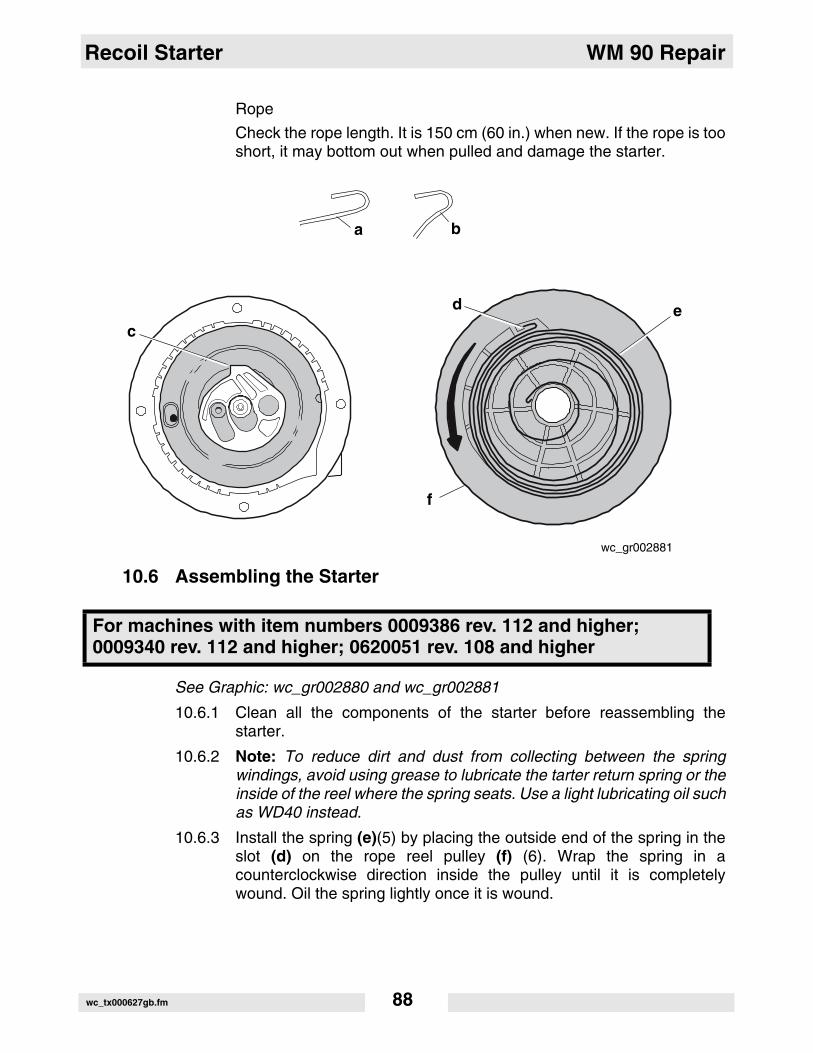
Recoil Starter WM 90 Repair
Rope
Check the rope length. It is 150 cm (60 in.) when new. If the rope is tooshort, it may bottom out when pulled and damage the starter.
10.6 Assembling the Starter
See Graphic: wc_gr002880 and wc_gr002881
10.6.1 Clean all the components of the starter before reassembling thestarter.
10.6.2 Note: To reduce dirt and dust from collecting between the springwindings, avoid using grease to lubricate the tarter return spring or theinside of the reel where the spring seats. Use a light lubricating oil suchas WD40 instead.
10.6.3 Install the spring (e)(5) by placing the outside end of the spring in theslot (d) on the rope reel pulley (f) (6). Wrap the spring in acounterclockwise direction inside the pulley until it is completelywound. Oil the spring lightly once it is wound.
For machines with item numbers 0009386 rev. 112 and higher; 0009340 rev. 112 and higher; 0620051 rev. 108 and higher
a
c
b
wc_gr002881
d e
f
wc_tx000627gb.fm 88

WM 90 Repair Recoil Starter
10.6.4 Lightly grease the center post of the housing and install the wear plate(4) and the rope reel pulley. Rotate the rope reel pulley until the springseats in the slot at the center of the housing (13). Install the washer (7)over the center post and seat it into the rope reel pulley.
NOTICE: Failure to replace the washer will cause the ratchet to bindand prevent the rope reel pulley from rotating freely.
10.6.5 Add the spring (8) and the ratchet (9) to the assembly. Do not greasethe ratchet.
10.6.6 Install the cover (10) and secure it in place using the lock washer (11)and locknut (12). Torque the locknut to 8 Nm (6 ft.lbs.). Install the ropeas described in section Starter Rope Replacement.
10.7 Replacing the Starter Rope
See Graphic: wc_gr002882
The starter rope can be replaced without removing the rope reel pulleyfrom the starter assembly.
Removal:
10.7.1 Remove the starter assembly from the flywheel housing.
10.7.2 Lift the rope through the notch (a) in the drum. Pull out as much of therope as possible. Hold the rope and let the spring pull the drum aroundclockwise until all spring tension is released.
10.7.3 Untie the knot and remove the rope.
Installation:
10.7.4 Thread the new rope through the rope reel pulley and then through thehousing. Install the handle and knot (b) each end of the rope as shown.Be sure the end of the rope does not protrude from the rope reel (c) orit may interfere with the movement of the starter.
10.7.5 Lift the rope up through the notch in the edge of the drum and rotatethe drum counterclockwise to wind the spring. Guide (d) the ropearound as the drum is rotated. After two complete revolutions, removethe rope from the notch and allow it to be pulled around the drum bythe spring tension (e). Repeat this procedure until all the rope is on thedrum and the handle rests against the housing.
10.7.6 Reattach the starter assembly to the flywheel housing.
For machines with item numbers 0009386 rev. 112 and higher; 0009340 rev. 112 and higher; 0620051 rev. 108 and higher
wc_tx000627gb.fm 89

Recoil Starter WM 90 Repair
wc_gr002882
a
d
e
b
c
wc_tx000627gb.fm 90

WM 90 Repair Clearance Data and Limits Table
11. Clearance Data and Limits Table
11.1 Term Descriptions
The following table lists critical dimensions of specific parts. The“Standard” column lists the dimension of the part as new from thefactory. The “Limit” column lists the maximum allowance. If themeasurement exceeds the “Limit” dimension listed, replace or repairthe part.
Item Standardmm (in.)
Limitmm (in.)
Cylinder headFlatness
0.05 or less(0.002)
0.1(0.004)
Intake/exhaust valve contact width
0.8–1.1(0.0315–0.0433)
2.0(0.079)
Intake exhaust
5.500–5.518(0.2165–0.2172)
---
wc_gr001921
wc_gr001922
wc_gr001923
wc_tx000391gb.fm 91
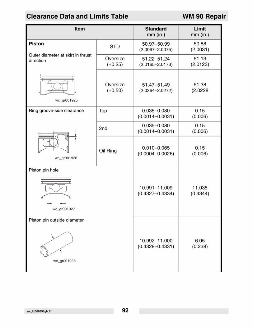
Clearance Data and Limits Table WM 90 Repair
Piston
Outer diameter at skirt in thrust direction
STD 50.97–50.99(2.0067–2.0075)
50.88(2.0031)
Oversize(+0.25)
51.22–51.24(2.0165–2.0173)
51.13(2.0123)
Oversize(+0.50)
51.47–51.49(2.0264–2.0272)
51.38(2.0228
Ring groove-side clearance Top 0.035–0.080(0.0014–0.0031)
0.15(0.006)
2nd0.035–0.080
(0.0014–0.0031)0.15
(0.006)
Oil Ring0.010–0.065
(0.0004–0.0026)0.15
(0.006)
Piston pin hole
10.991–11.009(0.4327–0.4334)
11.035(0.4344)
Piston pin outside diameter
10.992–11.000(0.4328–0.4331)
6.05(0.238)
Item Standardmm (in.)
Limitmm (in.)
wc_gr001925
wc_gr001926
wc_gr001927
wc_gr001928
wc_tx000391gb.fm 92

WM 90 Repair Clearance Data and Limits Table
Clearance between piston and cylinder at skirt
0.010–0.049(0.0004–0.0019)
0.25(0.010)
Piston ring end gapTop ring
0.15–0.35(0.006–0.014
1.5(0.0591)
2nd ring0.35–0.55
(0.014–0.0221.5
(0.0591)
Oil ring0.05–0.25
(0.002–0.0101.5
(0.0591)
Cylinder
Inner diameter StandardSTD 51.000–51.019
(2.008–2.009)
To be rebored when the differ-ence between max. and min. diameter reaches 0.1 (0.004).
First reboring51.250–51.269
(2.0177–2.0185)Same as above
Second reboring
51.500–51.519(2.0276–2.0283)
Same as above
Roundness after reboring Less than 0.01(0.0004)
Cylindricity after reboring Less than 0.01(0.0004)
Item Standardmm (in.)
Limitmm (in.)
wc_gr001929
wc_gr001930
wc_gr001924
wc_tx000391gb.fm 93
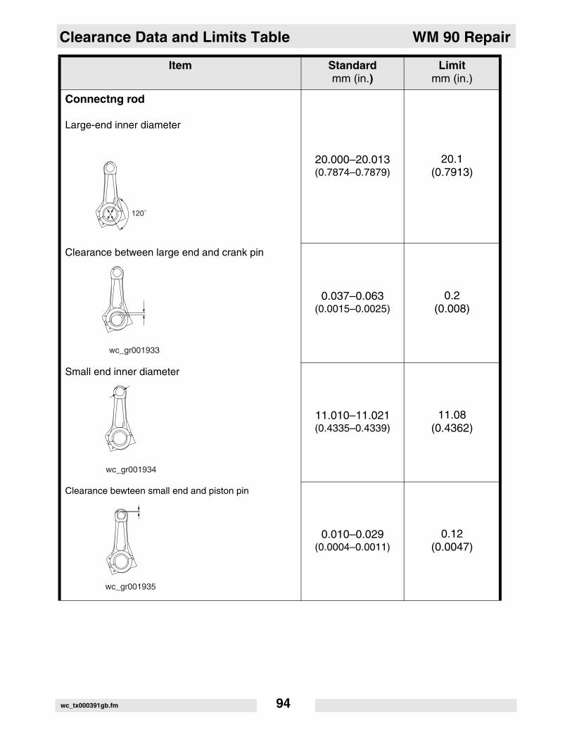
Clearance Data and Limits Table WM 90 Repair
Connectng rod
Large-end inner diameter
20.000–20.013(0.7874–0.7879)
20.1(0.7913)
Clearance between large end and crank pin
0.037–0.063(0.0015–0.0025)
0.2(0.008)
Small end inner diameter
11.010–11.021(0.4335–0.4339)
11.08(0.4362)
Clearance bewteen small end and piston pin
0.010–0.029(0.0004–0.0011)
0.12(0.0047)
Item Standardmm (in.)
Limitmm (in.)
120˚
wc_gr001933
wc_gr001934
wc_gr001935
wc_tx000391gb.fm 94

WM 90 Repair Clearance Data and Limits Table
Large end side clearance
0.1–0.7(0.004–0.028)
1.0(0.04)
Crankshaft
Crank pin outer diameter
19.950–19.963(0.7854–0.7859)
19.85(0.7815)
Journal outer diameter
D1 and D219.988–19.997(0.7869–0.7873)
---
Camshaft
Cam peak height (intake and exhaust)
18.3–18.5(0.720–0.728)
18.15(0.715)
Item Standardmm (in.)
Limitmm (in.)
wc_gr001936
wc_gr001937
wc_gr001938
D1 D2
wc_gr001939
wc_tx000391gb.fm 95
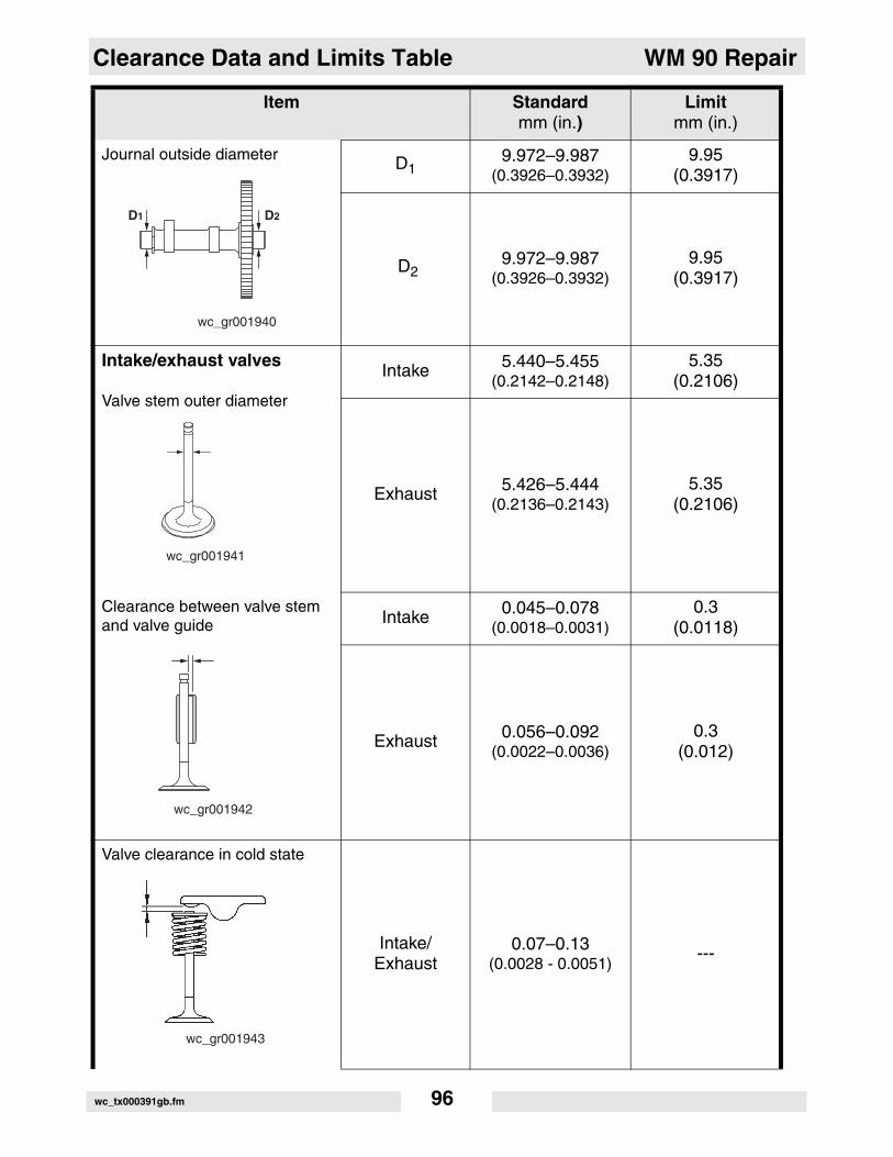
Clearance Data and Limits Table WM 90 Repair
Journal outside diameter D19.972–9.987
(0.3926–0.3932)9.95
(0.3917)
D29.972–9.987
(0.3926–0.3932)9.95
(0.3917)
Intake/exhaust valves
Valve stem outer diameter
Intake 5.440–5.455(0.2142–0.2148)
5.35(0.2106)
Exhaust 5.426–5.444(0.2136–0.2143)
5.35(0.2106)
Clearance between valve stem and valve guide Intake 0.045–0.078
(0.0018–0.0031)0.3
(0.0118)
Exhaust 0.056–0.092(0.0022–0.0036)
0.3(0.012)
Valve clearance in cold state
Intake/Exhaust
0.07–0.13(0.0028 - 0.0051)
---
Item Standardmm (in.)
Limitmm (in.)
wc_gr001940
D1 D2
wc_gr001941
wc_gr001942
wc_gr001943
wc_tx000391gb.fm 96
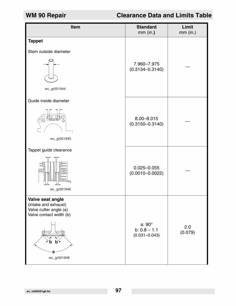
WM 90 Repair Clearance Data and Limits Table
Tappet
Stem outside diameter
7.960–7.975(0.3134–0.3140)
---
Guide inside diameter
8.00–8.015(0.3150–0.3140)
---
Tappet guide clearance
0.025–0.055(0.0010–0.0022)
---
Valve seat angle(intake and exhaust)Valve cutter angle (a)Valve contact width (b)
a: 90°b: 0.8 – 1.1
(0.031–0.043)
2.0(0.079)
Item Standardmm (in.)
Limitmm (in.)
wc_gr001944
wc_gr001945
wc_gr001946
wc_gr001948
b
a
b
wc_tx000391gb.fm 97

Clearance Data and Limits Table WM 90 Repair
Valve spring free length
26.7(1.05)
---
Item Standardmm (in.)
Limitmm (in.)
wc_gr001947
wc_tx000391gb.fm 98

WM 90 Repair Troubleshooting
12. Troubleshooting
12.1 Troubleshooting Introduction
If the engine shows any sign of malfunction, the cause should bedetermined immediately and the appropriate countermeasures shouldbe taken to prevent the problem from worsening. This troubleshootingsection describes certain known problems, their possible causes, andappropriate action to take. Note, however, that the list of problemslisted here is not all-encompassing. Generally speaking, since there isthe possibility of multiple causes for a single problem, please use yourexperience and common sense when deciding on what action to take.
The following three conditions must be met for the engine to start:
1. The cylinder must be filled with the proper fuel-air mixture.
2. There must be good compression in the cylinder.
3. There must be good spark, properly timed to ignite the mixture.
The engine cannot be started unless the these three conditions aremet. There are other factors as well that will make engine startingdifficult, such as a heavy load on the engine when attempting to start,or heavy back pressure due to a long exhaust pipe.
12.2 Troubleshooting Procedures
12.2.1 Fuel System Problems:
12.2.1.1 No gasoline in tank, or the fuel cock is closed.
12.2.1.2 The carburetor is not choked sufficiently especially when engine iscold.
12.2.1.3 Water, dust or gum in the gasoline interfering with fuel flow tocarburetor.
12.2.1.4 Inferior grade gasoline or poor quality gasoline not vaporized enoughto produce the correct fuel-air mixture.
12.2.1.5 The carburetor needle valve is held open by dirt or gum. This troublecan be detected as the fuel flows out of the carburetor when the engineis idling.
12.2.1.6 If the carburetor overflows, excessive fuel runs into the cylinder whenstarting the engine, making the fuel-air mixture too rich to burn. If thishappens, remove the spark plug and turn the starting pulley a few turnsto let the rich fuel-air mixture out of the spark plug hole and into theatmosphere. Keep the choke valve open during this operation. Dry thespark plug well, screw it into place, and try to start the engine again.
wc_tx000393gb.fm 99

Troubleshooting WM 90 Repair
12.2.2 Ignition System Problems:
Check the following when experiencing a lack of spark.
12.2.2.1 Wires of the ignition coil, spark plug, or contact breaker disconnected.
12.2.2.2 Ignition coil damaged or shorted.
12.2.2.3 Spark plug wire wet or soaked with oil.
12.2.2.4 Spark plug dirty or wet.
12.2.2.5 Spark plug gap incorrect.
12.2.2.6 Spark plug electrode connected or bridged.
12.2.2.7 Incorrect spark timing.
12.2.2.8 Proper connection of all wires.
12.2.3 Compression System:
If starting difficulties and loss of power are not due to the fuel systemor ignition system, the fault may be due to lack of compression. Makethe following checks to the compression system.
12.2.3.1 Internal engine is completely dry because of a long period of storage.
12.2.3.2 Loose or broken spark plug. This causes a hissing noise made by thefuel-air mixture running out of the cylinder in compression strokeduring cranking.
12.2.3.3 Damaged head gasket or loose cylinder head. This will also make ahissing noise.
12.2.3.4 If the correct compression is not obtained even after remedying theabove, problems may be due to incorrect valve clearance.Disassemble the engine and proceed further as follows:
• Valve stuck open due to carbon or gum on the valve stem.
• If the piston rings are stuck on the piston, remove the piston and con-necting rod from the engine. Clean and replace the parts if necessary.
12.2.4 Engine Misfires:
12.2.4.1 Incorrect spark plug electrode gap. Adjust gap.
12.2.4.2 Ignition cable worn.
12.2.4.3 Weak spark.
12.2.4.4 Ignition wire connections loose.
12.2.4.5 Water in gasoline.
12.2.4.6 Insufficient compression.
wc_tx000393gb.fm 100

WM 90 Repair Troubleshooting
12.2.5 Engine Stops:12.2.5.1 Fuel tank empty. Water, dirt, gum, etc. in gasoline.
12.2.5.2 Vapor lock. Gasoline evaporating in the fuel lines due to overheatingof the engine.
12.2.5.3 Vapor lock in the fuel lines or carburetor due to using too volatile gasblend (winter formula) in the hot season.
12.2.5.4 Air vent hole in the fuel tank cap plugged.
12.2.5.5 Bearing parts seized due to lack of lubrication.
12.2.5.6 Magneto or ignition coil faulty.
12.2.6 Engine Overheats:
12.2.6.1 Crankcase oil level low. Add oil immediately.
12.2.6.2 Spark timing incorrect.
12.2.6.3 Low-grade gasoline being used or engine is overloaded.
12.2.6.4 Cooling air circulation restricted.
12.2.6.5 Cooling air path misdirected causing loss of cooling efficiency.
12.2.6.6 Cylinder head cooling fins clogged with dirt.
12.2.6.7 Engine being operated in an enclosed space without sufficient coolingair.
12.2.6.8 Exhaust gas discharge restricted, or carbon deposits in thecombustion chamber.
12.2.6.9 Engine running on low-octane gasoline detonates due to heavy load atlow speed.
12.2.7 Engine Knocks:
12.2.7.1 Poor quality gasoline.
12.2.7.2 Engine operating under heavy load at low speed.
12.2.7.3 Carbon or lead deposits in the cylinder head.
12.2.7.4 Spark timing incorrect.
12.2.7.5 Loose connecting rod bearing due to wear.
12.2.7.6 Loose piston pin due to wear.
12.2.8 Engine Backfires Through Carburetor:
12.2.8.1 Water or dirt in gasoline, or low grade gasoline.
12.2.8.2 Intake valve stuck.
12.2.8.3 Valves overheated or hot carbon particles in the combustion chamber.
12.2.8.4 Engine cold.
wc_tx000393gb.fm 101

Troubleshooting WM 90 Repair
Noteswc_tx000393gb.fm 102

Threadlockers and Sealants
Threadlockers and Sealants
Threadlocking adhesives and sealants are specified throughout thismanual by a notation of “S” plus a number (S#) and should be usedwhere indicated. Threadlocking compounds normally break down attemperatures above 175°C (350°F). If a screw or bolt is hard toremove, heat it using a small propane torch to break down the sealant.When applying sealants, follow instructions on container. The sealantslisted are recommended for use on Wacker equipment.
TYPE( ) = Europe COLOR USAGE
PART NO. –SIZE
Loctite 222Hernon 420Omnifit 1150 (50M)
Purple Low strength, for locking threads smaller than 6 mm (1/4”).Hand tool removable.Temp. range: -54 to 149°C (-65 to 300°F)
73287 - 10 ml
Loctite 243Hernon 423Omnifit 1350 (100M)
Blue Medium strength, for locking threads larger than 6 mm (1/4”).Hand tool removable.Temp. range: -54 to 149°C (-65 to 300°F)
29311 - .5 ml17380 - 50 ml
Loctite 271/277Hernon 427Omnifit 1550 (220M)
Red High strength, for all threads up to 25 mm (1”).Heat parts before disassembly.Temp. range: -54 to 149°C (-65 to 300°F)
29312 - .5 ml26685 - 10 ml73285 - 50 ml
Loctite 290Hernon 431Omnifit 1710 (230LL)
Green Medium to high strength, for locking preassembled threads and for sealing weld porosity (wicking).Gaps up to 0.13 mm (0.005”)Temp. range: -54 to 149°C (-65 to 300°F)
28824 - .5 ml25316 - 10 ml
Loctite 609Hernon 822Omnifit 1730 (230L)
Green Medium strength retaining compound for slip or press fit of shafts, bearings, gears, pulleys, etc.Gaps up to 0.13 mm (0.005”) Temp. range: -54 to 149°C (-65 to 300°F)
29314 - .5 ml
Loctite 545Hernon 947Omnifit 1150 (50M)
Brown Hydraulic sealantTemp. range: -54 to 149°C (-65 to 300°F)
79356 - 50 ml
Loctite 592Hernon 920Omnifit 790
White Pipe sealant with Teflon for moderate pressures.Temp. range: -54 to 149°C (-65 to 300°F)
26695 - 6 ml73289 - 50 ml
Loctite 515Hernon 910Omnifit 10
Purple Form-in-place gasket for flexible joints.Fills gaps up to 1.3 mm (0.05”)Temp. range: -54 to 149°C (-65 to 300°F)
70735 - 50 ml

Threadlockers and Sealants
Threadlockers and Sealants (continued)
Threadlocking adhesives and sealants are specified throughout this manual by a notation of “S” plus a number (S#) and should be used where indicated. Threadlocking compounds normally break down at temperatures above 175°C (350°F). If a screw or bolt is hard to remove, heat it using a small propane torch to break down the sealant. When applying sealants, follow instructions on container. The sealants listed are recommended for use on Wacker equipment.
TYPE( ) = Europe COLOR USAGE
PART NO. –SIZE
Loctite 496Hernon 110Omnifit Sicomet 7000
Clear Instant adhesive for bonding rubber, metal and plastics; general purpose.For gaps up to 0.15 mm (0.006”)Read caution instructions before using.Temp. range: -54 to 82°C (-65 to 180°F)
52676 - 1oz.
Loctite Primer THernon Primer 10Omnifit VC Activator
AerosolSpray
Fast curing primer for threadlocking, retaining and sealing compounds. Must be used with stainless steel hardware. Recommended for use with gasket sealants.
2006124-6 oz.

Torque Values
Torque Values
Metric Fasteners (DIN)
TORQUE VALUES (Based on Bolt Size and Hardness) WRENCH SIZE
Size Nm ft.lb. Nm ft.lb. Nm ft.lb. Metric Inch Metric Inch
M3 1.2 *11 1.6 *14 2.1 *19 5.5 7/32 2.5 –
M4 2.9 *26 4.1 *36 4.9 *43 7 9/32 3 –
M5 6.0 *53 8.5 6 10 7 8 5/16 4 –
M6 10 7 14 10 17 13 10 – 5 –
M8 25 18 35 26 41 30 13 1/2 6 –
M10 49 36 69 51 83 61 17 11/16 8 –
M12 86 63 120 88 145 107 19 3/4 10 –
M14 135 99 190 140 230 169 22 7/8 12 –
M16 210 155 295 217 355 262 24 15/16 14 –
M18 290 214 405 298 485 357 27 1-1/16 14 –
M20 410 302 580 427 690 508 30 1-1/4 17 –
1 ft.lb. = 1.357 Nm * = in.lb. 1 inch = 25.4 mm
8.8 10.9 12.9

Torque Values
Torque Values (continued)
Inch Fasteners (SAE)
Size Nm ft.lb. Nm ft.lb. Nm ft.lb. Metric Inch Metric Inch
No.4 0.7 *6 1.0 *14 1.4 *12 5.5 1/4 – 3/32
No.6 1.4 *12 1.9 *17 2.4 *21 8 5/16 – 7/64
No.8 2.5 *22 3.5 *31 4.7 *42 9 11/32 – 9/64
No.10 3.6 *32 5.1 *45 6.8 *60 – 3/8 – 5/32
1/4 8.1 6 12 9 16 12 – 7/16 – 3/32
5/16 18 13 26 19 33 24 13 1/2 – 1/4
3/8 31 23 45 33 58 43 – 9/16 – 5/16
7/16 50 37 71 52 94 69 16 5/8 – 3/8
1/2 77 57 109 80 142 105 19 3/4 – 3/8
9/16 111 82 156 115 214 158 – 13/16 – –
5/8 152 112 216 159 265 195 24 15/16 – 1/2
3/4 271 200 383 282 479 353 – 1-1/8 – 5/8
1 ft.lb. = 1.357 Nm * = in.lb. 1 inch = 25.4 mm


Wacker Construction Equipment AG · Preußenstraße 41 · D-80809 München · Tel.: +49-(0)89-3 54 02 - 0 · Fax: +49 - (0)89-3 54 02-3 90Wacker Corporation · P.O. Box 9007 · Menomonee Falls, WI 53052-9007 · Tel. : (262) 255-0500 · Fax: (262) 255-0550 · Tel. : (800) 770-0957Wacker Asia Pacific Operations · Skyline Tower, Suite 2303, 23/F · 39 Wang Kwong Road, Kowloon Bay, Hong Kong · Tel. +852 2406 60 32 · Fax: +852 2406 60 21