Waterway Structures - Christchurch City Council
20
Wate rway Structures 13.1 Introduction 13 .2 Bridges and Culverts 13.3 Fords 13.4 Grills in Waterways 13.5 Floodgates and Flap Valves 13 .6 Pumping Stations 13.7 Stopbanks 13 .8 Waterway Structural Lining 13.9 Waterway Fences 13.10 References Waterways. Wetlands and Drainage Guide- Ko Te Anga Whakaora mii Ngii Ara wai Repii • Chri stchurch Cit y Council • 13 -1 Page 13-3 13-3 13-11 13- 11 13-14 13-15 13 - 18 13-18 13-19 13-20 Part B: De sign Febru ary 2003
Transcript of Waterway Structures - Christchurch City Council
Wate rway Structures
13. 1 Introduction
13.2 Bridges and Culverts
13.3 Fords
13.4 Grills in Waterways
13.5 Floodgates and Flap Valves
13.6 Pumping Stations
13.7 Stopbanks
13.8 Waterway Structural Lining
13.9 Waterway Fences
13.10 References
Waterways. Wetlands and Drainage Guide-Ko Te Anga Whakaora mii Ngii Arawai Repii • Christchurch City Council •
13- 1
Page
13-3
13-3
13-11
13- 11
13-14
13-15
13- 18
13-18
13-19
13-20
Part B: Design February 2003
13-2 Chapter 13: Waterway Structures
Part B: Design February 2003
Waterways , Wetlands and Drainage Guide-Ko Te Anga Whakaora mii Nga Arawai Repii Christchurch City Council
13.1 Introduction The traditional approach to designing waterway structures has been to ensure hydraulic capacity, structural integrity, and safety. While these criteria must be applied, the design process must consider all six values associated with waterbodies: ecology, landscape, recreation, heritage, cu lture, and drainage. Waterway structures include the following, which are outlined in the consecutive sections:
bridges and culverts
fords
grills and debris traps
floodgates and flap valves
pump stations
stopbanks
waterway structural linings
waterway fences.
13.2 Bridges and Culverts Approval from the Parks and Waterways Unit is required for all bridges and culverts, and a consent is required from Environment Canterbury. Designers are advised to seek Parks and Waterways advice prior to detailed design and any consent application.
Chapter 13 : Waterway Structures 13-3
13.2.1 Designing for a Range of Values
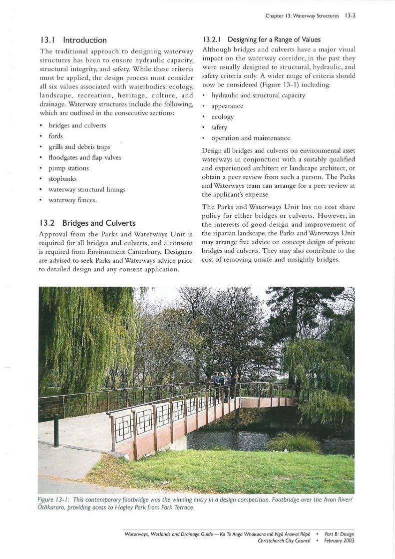
Although bridges and culverts have a major visua l impact on the waterway corridor, in the past they were usually designed to structural , hydraulic, and safety criteria only. A wider range of criteria should now be considered (Figure 13-1) including:
hydraulic and structural capacity
appearance
ecology
safety
operation and maintenance.
Design all bridges and culverts on envirol11nental asset waterways in conjunction with a suitably qualified and experienced architect or landscape architect, or obtain a peer review from such a person. The Parks and Watenvays team can arrange for a peer review at the applicant's expense.
The Parks and Waterways Unit has no cost share policy for either bridges or culverts. However, in the interests of good design and improvement of the riparian landscape, the Parks and Waterways Unit may arrange free advice on concept design of private bridges and culverts. They may also contribute to the cost of removing unsafe and unsightly bridges.
Fjgure 13-1 : This contemporary foo tbridge was the winning entry in a design competition. Footbridge over the Avon River/ Otakaroro, providing acess to Hagley Park from Park Terrace.
Waterways, Wetlands and Drainage Guide-Ko Te Anga Whakaora rnii Ngii Arawai Repii • Christchurch City Council •
Part B: Design February 2003
13-4 Chapter 13: Waterway Structures
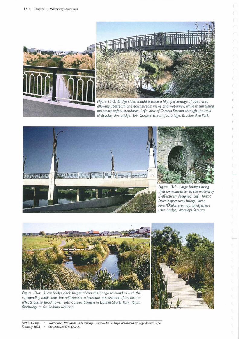
"--"iiiii Figure 13-2: Bridge sides should provide a high percentage of open area allowing upstream and downstream views of a waterway, while maintaining necessary safety standards. Left: view of Corsers Stream through the rails of Brooker Ave bridge. Top: Corsers Stream footbridge , Brooker Ave Park.
Figure 13-4: A low bridge deck height allows the bridge to blend in with the surrounding landscape, but will require a hydraulic assessment of backwater effects during flood flows. Top: Corsers Stream in Donnel Sports Park. Right: footbridge in OWkaikino wetland.
Figure 13-3: Large bridges bring their own character to the waterway if effectively designed. Left: Anzac Drive expressway bridge, Avon River/Otiikaroro. Top: Bridgemere Lane bridge, Worsleys Stream.
Part B: DeSign February 2003
• Waterways , Wet lands and Drainage Guide - Ko Te Anga Whakaora rno Ngo Arawai Repo • Christchurch City Council
13.2.2 Design Considerations
13.2.2.1 Appearance
Bridge and culvert sides and handrails must allow a view upstream and downstream of the waterway (Figure 13-2) . Bridge sides should provide a high percentage of open area and be as low as possible, yet provide the safety constraints necessary.
A consistent style or design for bridges , including handrails, should be encouraged for every waterway reach. Consider reducing the number of bridges by promoting shared access.
Where the conditions limit the choice of materials and their consequent appea rance in the structures themselves, thought should be given to landscaping with appropriate plantings to screen or soften any 'hard' structures. It is accepted that in some situations structures will dominate the landscape and contribute their own character. For example, some of the larger bridges over major waterways, and older colonial bridges bring their own character to the waterway's landscape (Figure 13-3) . In such situations where a bridge will dominate the landscape it is important to ensure an effective visual design.
For minor bridges, deck and approach level should, where possible, be lower than the level of the street footpath or road verge. This will ensure bridge deck height and approaches blend in with the surrounding landscape (Figure 13-4) . Lowering of minor bridge decks can allow water to flow across the deck in a controlled manner during an extreme flood. Note however, that a hydraulic check of backwater effects will need to be carried out wherever bridges may be submerged during extreme flood events.
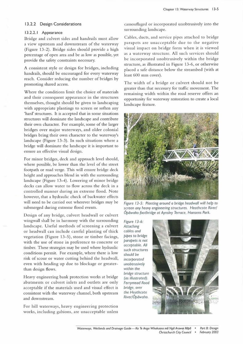
Design of any bridge, culvert headwall or culvert wingwall shall be in harmony with the surrounding landscape. Useful methods of screening a culvert or headwall can include careful planting of thick vegetation (Figure 13-5), stone or timber fac ings , with the use of stone in preference to concrete or timber. These strategies may be used where hydraulic conditions permit. For example, where there is low risk of scour or water cutting behind the headwall , even with heading up due to blockage or greaterthan design flows.
H eavy engineering bank protec tion works at bridge abutments or culvert inlets and outlets are only acceptable if the mate rials used and visual effect is consistent with the waterway channel, both upstream and downstream.
For hill waterways, heavy engineering protec tion works, including gabions, are una cce ptable unless
Chapter 13: Waterway Structures 13-5
camouflaged or incorporated unobtrusively into the surrounding landscape.
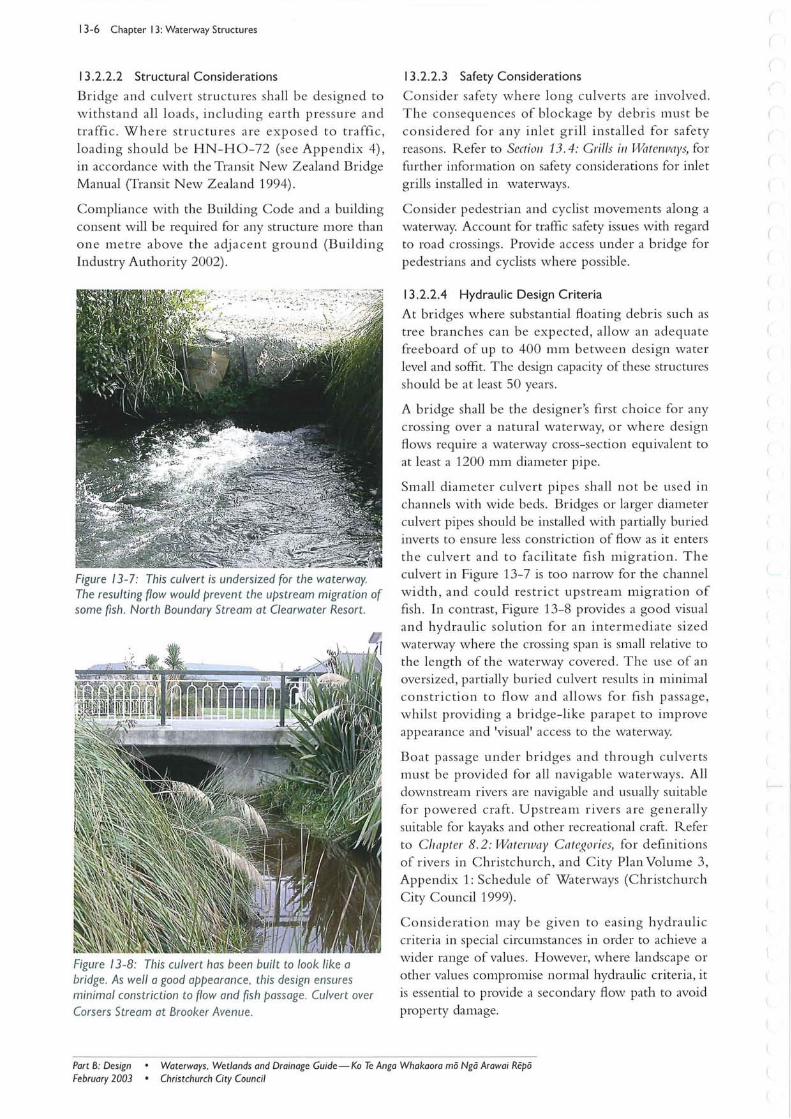
Ca bles, ducts, and service pip es attached to bridge parapets are un acce ptabl e due to the ne ga tive visual impact on bridge form when it is viewed as a waterway structure. All such services should be incorporated unobtrusively within the bridge structure, as illustrated in Figure 13-6, or otherwise placed a safe distance below the streambed (with at least 600 mm cover) .
The width of a bridge or culvert should not be greater than that necessary for traffic movement. The remaining width within th e road reserve offers an opportunity for waterway restoration to create a local landscape feature .
Figure 13-5: Planting around a bridge headwall will help to screen any heavy engineering structures. Heathcote River/ Opowaho footbridge at Aynsley Terrace. Hansens Park.
Figure 13-6: Attaching cables and pipes to bridge parapets is not acceptable. All such structures should be incorporated unobtrusively within the bridge structure (as illustrated) . Ferrymead Road bridge. over the Heathcote River/Opowaho.
Waterways . Wetlands and Drainage Guide-Ko Te Anga Whakaora mo Ngo Arawai Repo • Part B: Design February 2003 Christchurch City Council •
13-6 Chapter 13: Waterway Structures
13 .2.2.2 Structural Considerations
B ridge and culve rt structures shall be designed to w ithstand all loads, including ea rth press ure and t ra ffic. Whe re stru c tures a re exp ose d to traffic, loa ding sho uld be HN-HO - 72 (see App e ndix 4) , in accordance with the Transit N ew Zealand Bridge M anual (Transit N ew Z ealand 1994).
Compliance with the Building Code and a building consent will be required for any structure more than o n e m e tre above the adj acent g ro und (Building Industry Authority 2002).
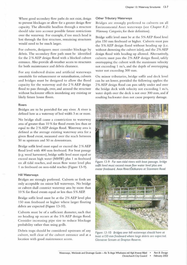
Figure 13-7: This culvert is undersized for the waterway. The resulting flow would prevent the upstream migration of some fi sh. North Boundary Stream at Clearwater Resort.
Figure 13-8: This culvert has been built to look like a bridge. As well a good appearance. this design ensures minimal constriction to flow and fish passage. Culvert over Corsers Stream at Brooker Avenue.
13 .2.2.3 Safety Considerations
Co nside r sa fe ty w h ere lo ng culve rts a re involved. T he co nse qu ences of blockage by debris mu st be co nsidered for any inle t g rill installe d for safe ty reasons. Refer to Secfioll 13.4: G rills ill Wl1 ferwl1)'~~ for further information on safety considerations for inlet grills installed in waterways.
Co nsider pedestrian and cyclist m ovem ents along a wa terway. Account for traffic safety issues w ith regard to road crossings. Provide access under a bridge for pedestrians and cyclists w here possible.
13 .2.2.4 Hydraulic Design Criteria
At bridges where substan tial floating debris such as tree branches ca n be expec ted , allow an adequate freeboard of up to 400 mm between design wa ter level and soffit. The design capacity of these structures sho uld be at least 50 yea rs.
A bridge shall be the designer 's first choice for any crossing ove r a natural wa terway, or whe re design flows require a wa terway cross- sec tio n equivalent to at least a 1200 mm diameter pipe.
Small diameter culvert pipes shall not be use d in channels with wide beds. Bridges or larger diameter culvert pipes should be installed with partially buried inverts to ensure less constrictio n of flow as it enters th e culvert and to facilita te fi sh mi g ration . Th e culvert in Figure 13-7 is too narrow for the channel w idth , and could res tri c t upstrea m mig rati o n o f fi sh . In contrast, Figure 13-8 provides a good visual and hydraulic solutio n for an inte r m ediate size d waterway where the crossing span is small relative to the length of the wa terway covered . The use of an oversized, partially buried culvert results in minimal co nstri c tion to flow and all ows fo r fi sh p assage, w hilst providing a bridge-like p arape t to improve appearance and 'visual' access to the waterway.
Boa t pa ssage under bridges and th ro u gh culve rts mu st be provided for all nav igable waterways. All downstrea m rivers are navigable and usually suitable for p owe red craft . Upstrea m rive rs are ge n erally suitable for kayaks and other recrea tional craft. R efer to C llI1jJfer 8. 2 : f;Vl1ferwllY Cil fegories, fo r definiti o ns of rivers in Christchurch , and C ity Plan Volume 3 , Appendix 1: Schedule o f Waterways (Christchurch City Council 1999).
Co nside ration m ay be g ive n to easing hydraulic criteria in special circumstances in order to achieve a wide r range of valu es. H owever, where landscape o r other values compromise normal hydra ulic criteria, it is essential to provide a secondary flow path to avoid property damage.
Part B: DeSign February 2003
• Waterways. Wetlands and Drainage Guide - Ko Te Anga Whakaora ma Nga Arawai Repa • Christchurch City Council
Where good secondary flow paths do not exist, design to prevent blockages or allow for a grea ter design flow capacity. The allowa ble headloss through a stru cture should take into account possible future restrictions over the wa terway. For example, if too much head is lost through the first stru ctu re, remaining stru ctures would need to be much larger.
Fo r culve rts, designers must consid er blockage by debris. The secondary flow path must be identified fo r the 2 % AEP design flood with a blocked culvert entrance. Also provide all-weather access to structures for both maintenance and debris clearance.
For any timbered drains and artificial wate rways unsuitable for enhancement or naturalisation, culverts and bridges must be designed to allow th e fl ood capacity for the wa terway and the 2 % AEP design flood to pass throu gh, over, and around the stru cture without backwater effects inundating any existing or likely future house floors.
Rivers
Bridges are to be provided fo r any rive r. A river is defined here as a waterway of bed width 3 m or more.
No bridge shall ca use a co nstric tio n to wate rway area of grea ter than 10 % for flood events less than or equal to the 2 % AEP design flood. Waterway area is defined as the ave rage existing wa terway area for a given flood event, measured over the reach between 50 m upstream and 50 m downstream.
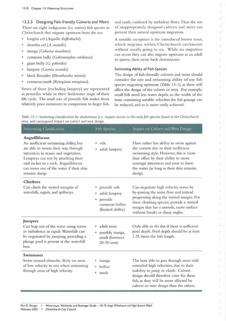
Bridge soffit level must equal or exceed the 2 % AEP flood level with 400 mm freeboard. For boat passage (e.g. weed harvesters), bridge soffit level must equal or exceed mean high water (MHW) plus 1 111 freeboard on all tidal reaches, and mea n flow water level plus 1 m freeboard on non-tidal reaches (Figure 13- 9).
Hill Waterways
Bridges are strongly preferred. Culverts or fords are only acceptable on minor hill waterways. N o bridge or culvert shall constrict wa terway area by more than 10 % for flood events equ al o r less than 5 % AEP
Bridge soffit level must be at the 2 % AEP level plus 150 mm freeboard o r higher w here larger fl oa ting debris are expected (Figure 13-10).
C ulverts mu st be of a sufficient diameter, such that no heading up occurs at the 5 % AE P design flood. Co nside r increasing pipe size to redu ce blockage probability rather than using grills.
D ebris traps should be considered upstrea m of any culvert , well clea r o f the culvert entrance and at a loca tion with good maintenance access.
Chapter 13: Waterway Structures 13-7
Other Tributary Waterways
B ridges are stro n gly prefe rred to culve r ts o n all E nviro nmental Asse t waterways (see C hapter 8.2: JlVaterwa)' Categories, for their definition).
Bridge soffi t level must be at the 5 % AEP flood level plus 150 mm freeboard or higher. C ulverts must pass the 5 % AEP design flood w ithout heading up (i. e. withou t drowning the culvert inlet) , and the 2 % AEP design flood with heading up allowed . Alternatively, culver ts must pass the 2 % AE P des ign flo od , safely overtopping the culve rt with the maximum velocity not exceeding 1 mis, and the depth of overtopping wa ter not exceeding 300 mm.
On minor tributaries , bridge soffi t and dec k level can be set lower, provided the following applies: the 2 % AEP design flood can pass safely under and over the bridge deck with velocity not exceeding 1 mis , water depth over the deck is not over 300 mm, and if resulting backwater does not cause property damage.
Figure 13-9: For non-tidal rivers with boat passage, bridge soffit level must exceed mean flow water level plus one meter freeboard . Avon River/Otakaroro at Stanmore Road.
Figure 13- 10: Bridges over hill waterways should have at least alSO mm freeboard where large debris are expected. Glenstrae Stream at Drayton Reserve.
Waterways, Wetlands and Drainage Guide-Ko Te Anga Whakaora mii Ngii Arawai Repii • Part B: Design February 2003 Christchurch City Council •
13-8 Chapter 13: Waterway Structures
13.2.3 Designing Fish-friendly Culverts and Weirs
There are eight indigenous (i .e. native) fish species in Christchurch that migrate upstream from the sea:
and easily confused by turbulent flows . Thus the use of inappropriately designed culverts and weirs can prevent their natural upstream migration.
longfin eel (Allguilla di~{fellbachi/)
shortfin eel (A. australis)
inanga (Galaxias iliaCI/latus)
common bully (Gobiolllorpifl/s cotidiafllfs)
giant bully (G. gobioides)
lamprey (Geotria alfstralis)
black flounder (Rholllbosolea retiaria)
common smelt (Retropinlla retropill/w).
A notable exception is the introduced brown trout, which migrates within Christchurch catchments withou t usually going to sea. While sea migra tion can occur they can also migrate upstream as an adult to spawn, then swim back downstream.
Swimming Ability of Fish Species
Seven of these (excluding lamprey) are represented as juveniles while in their freshwater stage of their life cycle. The small size of juvenile fish makes them relatively poor swimmers in comparison to larger fish,
The design of fish-friendly culverts and weirs should consider the size and swimming ability of any fish species migrating upstream (Table 13-1), as these will affect the design of the culvert or weir. For example, small fish need less water depth , so the width of the zone containing suitable velocities for fish passage can be reduced, and so is more easily achieved.
Table 13- 1: Swimming classification for diadromous (i .e. require access to the sea) fish species found in the Christchurch area, and consequent impact on culvert and weir design.
Swinmung Classification Fish Species Impact on Culvert and Weir Design
Anguilliforms
An inefficient swimming ability, but are able to worm their way through interstices in stones and vegetation. Lampreys can rest by attaching their oral sucker to a rock. Anguilliforms can 1110ve out of the water if their skin remains damp.
Climbers Can climb the wetted margins of waterfalls , rapids, and spillways.
Jumpers Can leap out of the water using waves or turbulence in rapids. Waterfalls can be negotiated by jumping, providing a plunge pool is present at the watel{all base.
Swimmers
Swim around obstacles. Rely on areas of low velocity to rest when swimming through areas of high velocity.
• eels
• adult lamprey
• juvenile eels
• adult lamprey
• juvenile coml11on bullies (limited ability)
• adult trout
• possibly inanga, smelt (between 20-50 111111)
• inanga
• bullies
• smelt
Have rather less ability to swim against the current due to their inefficient swimming style. However, this is more than offset by their ability to move amongst interstices and even to leave the water (as long as their skin remains damp) .
Can negotiate high velocity zones by by-passing the main flow and instead progressing along the wetted margin. For these climbing species, provide a wetted margin that has a smooth, moist sUlface without breaks or sharp angles.
Only able to do this if there is sufficient pool depth. Pool depth should be at least 1.25 times the fish length.
The least able to pass through areas with extended high velocities, due to their inability to jump or climb. Culvert design should therefore cater for these fish, as they will be more afiected by culvert or weir design than the others .
Part B: DeSign February 2003
• Waterways. Wetlands and Drainage Guide - Ko Te Anga Whakaora mo Nga Arawai Repo • Christchurch City Council
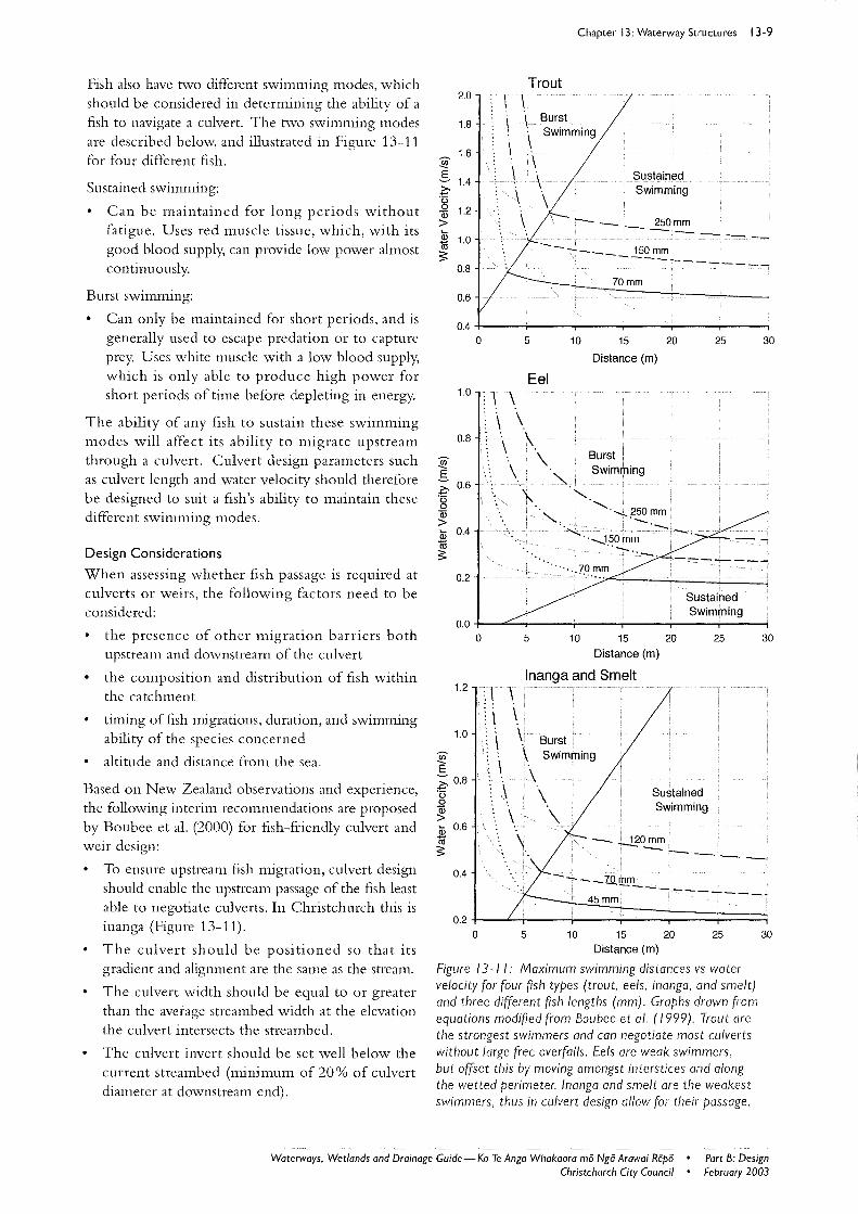
Fish also have novo different swimming modes, which should be considered in determining the ability of a fish to navigate a culvert. The novo swimming modes are described below, and illustrated in Figure 13-11 for four different fish.
Sustained swimming:
Can be maintained for long periods without fatigue. Uses red muscle tissue, which, with its good blood supply, can provide low power almost continuously.
Burst swimming:
Can only be maintained for short periods, and is generally used to escape predation or to capture prey. Uses white muscle with a low blood supply, which is only able to produce high power for short periods of time before depleting in energy.
The ability of any fish to sustain these swimming modes will affect its ability to migrate upstream through a culvert. Culvert design parameters such as culvert length and water velocity should therefore be designed to suit a fish's ability to maintain these different swimming modes.
Design Considerations
When assessing whether fish passage is required at culverts or weirs, the following factors need to be considered:
the presence of other migration barriers both upstream and downstream of the culvert
the composition and distribution of fish within the catchment
tinung of fish nugrations, duration, and swimnung ability of the species concerned
altitude and distance from the sea.
Based on New Zealand observations and experience, the following interim recommendations are proposed by Boubee et al. (2000) for fish-friendly culvert and weir design:
To ensure upstream fish migration, culvert design should enable the upstream passage of the fish least able to negotiate culverts. In Christchurch this is inanga (Figure 13-11).
The culvert should be positioned so that its gradient and alignment are the same as the stream.
The culvert width should be equal to or greater than the average streambed width at the elevation the culvert intersects the streambed.
The culvert invert should be set well below the current streambed (minimum of 20% of culvert diameter at downstream end).
Chapter 13: Waterway Structures 13-9
2.0
1.8
1.6 ~
5 1.4 Z=-'0 0 1.2 Qi >
Trout \ \ Burst \ Swimming
\
\
\ \
Sustained Swimming
- _ 250mm Qi 1.0 ------1ii -------___ 150mm S
0.8 ------------
0.6
0.4 0
1.0
0.8
.!!!. 5
0.6 .~ 0 0 Qi > Qi 0.4 1ii
5
Eel ~ \ \ ~ \ \ ~ \ : \ \ ~ \ "
70mm
10 15 20
Distance (m)
Burst Swimming
:'" \ "--"""'_250mm
'--'--'-
25 30
S -------0.2
····.:.7.0.~~ /""'----~---.:
0.0 0
1.2
1.0
~ E ;:: 0.8 -13 0 Qi > Qi 0.6 1ii S
0.4
0.2 0
1 \ \ \ \
\ \
\ \.
Sustained Swimming
5 10 15 20 25
Distance (m)
Inanga and Smelt
\ Burst.
'- Swimming
\ \
\
Sustained Swimming
:.. \ - -1.?0~ ------ -- -- __ 'ZQ, mm
45mm ----------
5 10 15 20 25
Distance (m)
Figure 13-11; Maximum swimming distances vs water velocity for four ftsh types (trout, eels, inanga, and smelt) and three different ftsh lengths (mm). Graphs drawn from equations modifted from Boubee et 01. (1999). Trout are the strongest swimmers and can negotiate most culverts without large free overfalls. Eels are weak swimmers, but offset this by moving amongst interstices and along the wetted perimeter. Inanga and smelt are the weakest swimmers, thus in culvert design allow for their passage.
30
30
Waterways. Wetlands and Drainage Guide - Ko Te Anga Whakaora mii Ngii Arawai Repii • Part B: Design February 2003 Christchurch City Council •
13-10 Chapter 13: Waterway Structures
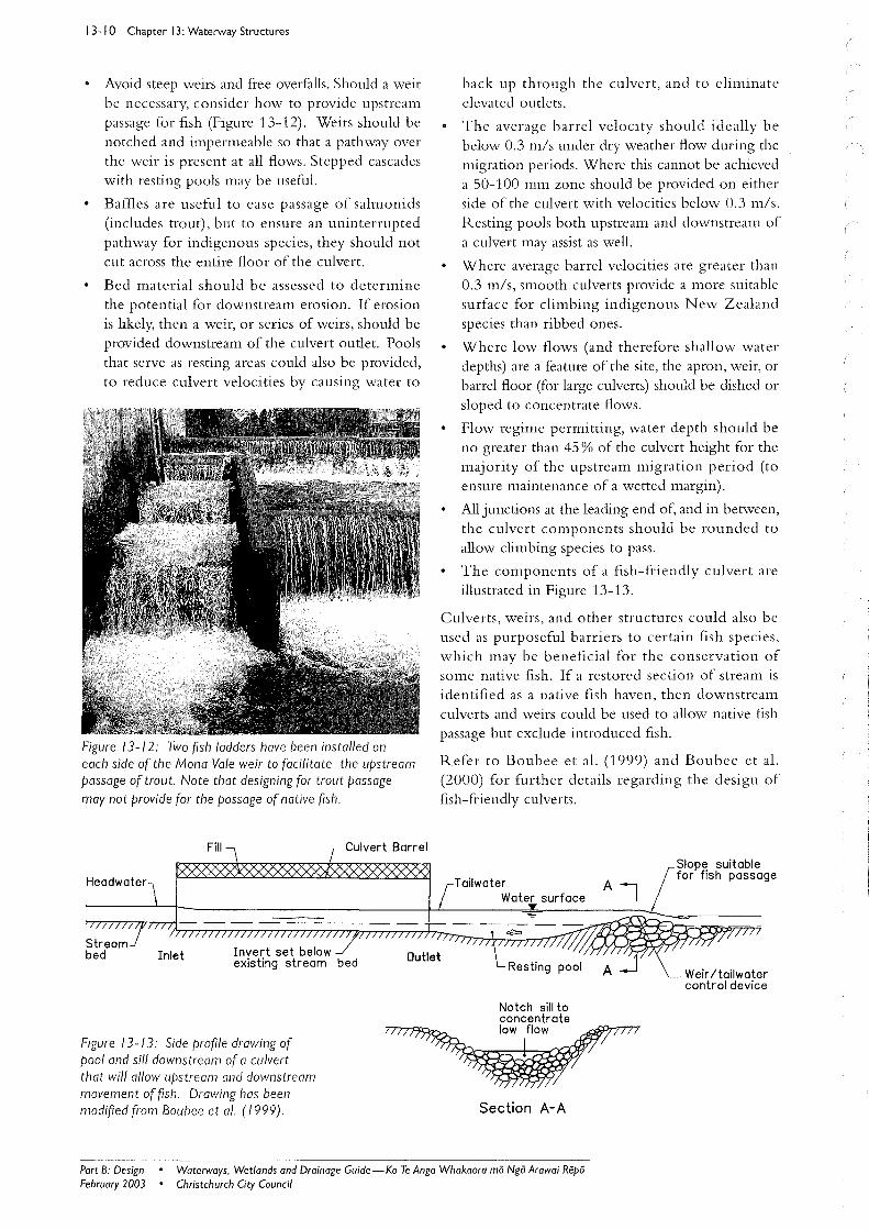
Avoid steep weirs and fi'ee overfalls. Should a weir be necessary, consider how to provide upstrearll passage for fish (Figure 13-12). Weirs should be notched and impermeable so that a pathway over the weir is present at all flows. Stepped cascades with resting pools may be useful.
Baffles are useful to ease passage of salmonids (includes trout), but to ensure an uninterrupted pathway for indigenous species, they should not cut across the entire floor of the culvert.
Bed material should be assessed to determine the potential for downstream erosion. If erosion is likely, then a weir, or series of weirs, should be provided downstream of the culvert outlet. Pools that serve as resting areas could also be provided, to reduce culvert velocities by causing water to
Figure 13-12: Two {Ish ladders have been installed on each side of the Mona Vale weir to facilitate the upstream passage of trout. Note that designing for trout passage may not provide for the passage of native fish.
Fill
Inlet
Figure 13-13: Side pro{lle drawing of pool and sill downstream of a culvert that will allow upstream and downstream movement of {Ish. Drawing has been modified from Boubee et 01. (/999).
Culvert Barrel
back up through the culvert, and to eliminate
elevated outlets.
The average barrel velocity should ideally be below 0.3 mls under dry weather flow during the migration periods. Where this cannot be achieved a 50-100 mm zone should be provided on either side of the culvert with velocities below 0.3 m/s. Resting pools both upstream and downstream of
a culvert may assist as well.
Where average barrel velocities are greater than 0.3 mis, smooth culverts provide a more suitable surface for climbing indigenous New Zealand
species than ribbed ones.
Where low flows (and therefore shallow water depths) are a feature of the site, the apron, weir, or barrel floor (for large culverts) should be dished or sloped to concentrate flows.
Flow regime permitting, water depth should be no greater than 45 % of the culvert height for the majority of the upstream migration period (to ensure maintenance of a wetted margin).
All junctions at the leading end of, and in between, the culvert components should be rounded to
allow climbing species to pass.
The components of a fish-friendly culvert are
illustrated in Figure 13-13.
Culverts, weirs, and other structures could also be used as purposeful barriers to certain fish species, which may be beneficial for the conservation of some native fish. If a restored section of stream is identified as a native fish haven, then downstream culverts and weirs could be used to allow native fish passage but exclude introduced fish.
Refer to Boubee et a1. (1999) and Boubee et a1. (2000) for further details regarding the design of fish-friendly culverts.
Tailwater Water surface
Section A-A
Slope suitable for fish passage
Weir / tailwater control device
Part B: Design February 2003
• Waterways, Wetlands and Drainage Guide-Ko Te Anga Whakaora rna Nga Arawai Repa • Christchurch City Council
13.3 Fords Because ford design is very site-specific, there is no actual standard design . Seek guidance from the Christchurch City Council for detailed design of fords . The following checklist provides a starting point in planning for fords. The checklist applies only to low volume, light traffic where speeds of less than 5 kph are expected.
Consider the following:
Site aesthetics, and whether a ford is needed.
The kinds of traffic expected (e.g. pedestrian, bicycle, car, bus).
Whether the ford is to be wet or dry at low flow. This will depend on a number of factors, including the type and volume of traffic, the risks and consequences of water on the surface, and at what stage the ford will be flooded.
Low flow conduits if applicable. Consider possible downstream scour, loadings, blockage potential, and aesthetics.
The probability of flooding over the ford and the associated risks and consequences.
The depth, width, and velocity of flow, as well as sediment and floating debris content.
Approach gradients, including the vertical and horizontal curves. Approach gradients will depend on vehicle configuration, sight distances, traction requirements, and site conditions and layout.
Side batters on approaches.
The effect of stormwater channelling down the ford.
The design foundation and running surface of approaches .
Design foundation and running sl11{ace through the bed of the waterway.
Erosion in the waterway, especially of the ford surfaces and downstrealTl of the ford.
The need to obtain consents for any work within a waterway.
Whether there is a need to provide for fish passage. Where there are existing weirs or fords with a vertical face, large rock-filled gabion mattresses can be placed at the downstream end in order to create a 'natural rapid' effect or cascade, and to remove any free-fall of water. This cascade area will enable fIsh to utilise the natural irregularities in water velocity around the rocks, and crevices amongst the rocks. Such irregularities will enable the fish to rest and avoid the current during their upstream migration (Mitchell 1990).
Chapter 13: Waterway Structures 1 3-1 1
13.4 Grills in Waterways The two primary purposes for installing a grill are safety (keeping people and especially children away from dange r), and the separation of debris from water to prevent:
pipe blockages
tidegates or flap valves jamming open
damage to flood pumps.
The decision to use a grill often involves weighing the two primary purposes given above, against the possible blockage of the grill. The provision of grills is, at times, desirable for safety and debris separation. However, the problems associated with blocked grills are so important that a very careful assessment is necessary before any decision can be made. Definitions of different types of debris traps, including grills, are given in Table 13-2.
13.4.1 Public Safety Considerations
In considering the following categories, be aware that the need for safety barriers is far higher in residential areas and other areas frequented by children.
Long, Large Diameter Culverts
These are> 50 m length, and> 700 mm diameter.
The need for a grill or other barrier is greater at the upstream end of a culvert where, as well as voluntary entry in dry conditions, children could be washed in by flood flows .
In a long culvert, a child could be trapped underwater long enough to drown.
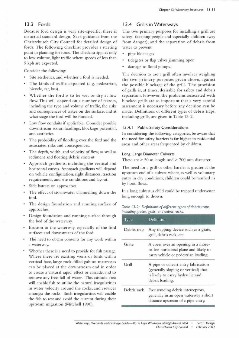
Table 13-2: Definitions of different types of debris traps, including grates, grills, and debris racks.
Type Definition
Debris trap Any trapping device such as a grate, grill, debris rack, etc.
Grate A cover over an opening in a moreor-less horizontal plane and likely to carry vehicle or pedestrian loading.
Grill A pipe or culvert entry fabrication (generally sloping or vertical) that is likely to carry hydraulic and debris loading.
Debris rack Free standing debris interceptors, generally in an open watelway a short distance upstream of a pipe entry.
Waterways. Wetlands and Drainage Guide-Ko Te Anga Whakaora mii Ngii Arawai Repii • Christchurch City Council •
Part B: Design February 2003
13-12 Chapter 13: Waterway Structures
Short, Large Diameter Culverts
A grill should be considered if there is deep ponded water within the culvert or a hidden step down on the invert, otherwise the danger level could normally be considered as low.
Small Diameter Pipelines/Culverts
Protection is not usually required for these. However, in the case of culverts steeper than, say 1 in 2, w here a small child could fall in and slide down, protection should be considered at the upper end if the diameter exceeds 300 mm.
Floodpumps
Pumps normally require a safety barrier.
13.4.1.1 Design Approaches for Safety
A grill should be considered as a last resort-consider the following alternative options first.
Fence off access (e.g. use see-through fences and informal surveillance) from areas that are readily frequented by small children, and rely on difficulty of access for limiting approach from the open waterway itself.
Consider using dense or prickly vegetation to discourage access. It may be difficult to establish plants under 'play' conditions.
Erect signs warning of danger.
Where a grill is used, a section should be removable to allow an unrestricted flood flow during a storm. A grill can be top hinged so that it swings clear if water level builds up b ecause of trapped debris, especially at o utlets. Shear pins are considered unsatisfactory because of their unpredictability.
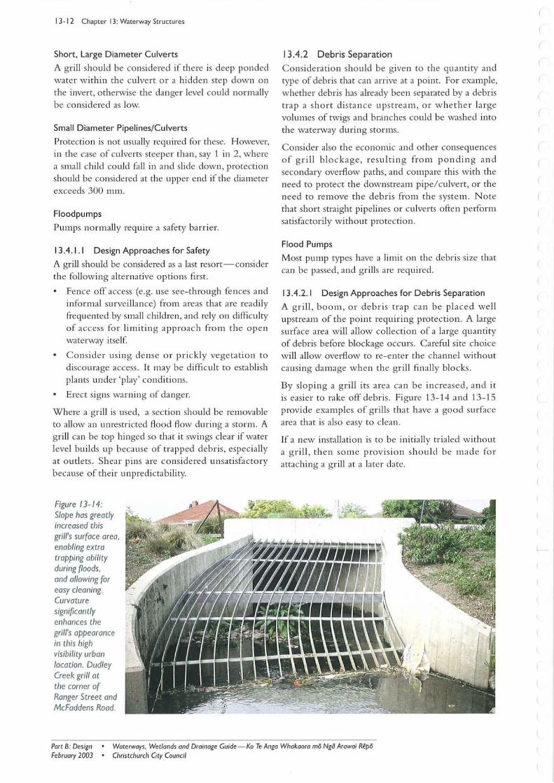
Figure 13-1 4: Slope has greatly increased this grill's surface area, enabling extra trapping abili ty during floods, and allowing for easy cleaning. Curvature Significantly enhances the grill's appearance in this high visibility urban location. Dudley Creek grill at the corner of Ranger Street and McFaddens Road.
13.4.2 Debris Separation
Consideration should be given to the quantity and type of debris that can arrive at a point. For example, whether debris has already been separated by a debris trap a short distance upstream, or whether large volumes of twigs and branches could be washed into the waterway during storms.
Consider also the economic and other consequences of g rill blockage, re sultin g from ponding and secondary overflow paths, and compare this with the need to protect the downstream pipe/culvert, or the need to remove the debris from the system. N ote that short straight pipelines or culverts often pelform satisfactorily without protection.
Flood Pumps
Most pump types have a limit on the debris size that can be passed, and grills are required.
13.4.2.1 Design Approaches for Debris Separation
A gri ll , boom, or debris trap can be placed well upstream of the point requiring protection. A large sUlface area will allow collection of a large quantity of debris before blockage occurs. Careful site choice will allow overflow to re-enter the channel without ca using damage when the grill fll1ally blocks.
By sloping a grill its area can be increased, and it is easier to rake off debris. Figure 13-14 and 13-15 provide examples of grills that have a good surface area that is also easy to clean.
If a new installation is to be initially trialed without a grill, then some provision should be m ade for attaching a grill at a later date.
Part B: DeSign February 2003
• Waterways. Wetlands and Drainage Guide - Ko Te Anga Whakaora mii Ngii Arawai Repii • Christchurch City Council
13.4.3 Grill Design Criteria
Bar Spacing
For safety purposes, 200 mm shall be the normal clear space between bars to prevent accidental passage of a child into a line. Spacing needs to be reduced to 100 mm if it is necessary to exclude a small determined child. Bars should also be stiff enough to prevent bending sideways.
For debris separation, spacing should be no more than 40 % of pipe diameter, with a maximum of 200 mm.
Grills protecting pumps should have an opening related to the size of particle that the pump can pass. This may be as little as 30 mm.
Grill Area
Grill area should be large enough to hold all trapped debris, without blocking, until staff can clear it during a storm. The amount of debris will be influenced by the nature of the catchment (e.g. areas with bush can generate quantities of floating branches and twigs during a storm) . Debris arriving at a grill will be substantially reduced if a debris rack (refer back to Table 13-2 for the definition of a debris rack) can be installed further upstream.
Suitable grill areas range from two to ten times the cross-sectional area of the conduit being protected, depending on the likely debris quantities and the consequences of blockage.
Economic sizing of a grill involves weighing the cost of a large grill against the cost of damage that would result from its blockage.
Clearing
Grills should be shaped and located to make clearing as easy as practicable during storms. A suitable platform for maintenance personnel and safe access should also be included.
Sloping grills with bars in a vertical plane tend to be easy to rake. Meshes should be avoided. If large debris is expected, consider some form of slipway to ease hauling debris from the channel.
If a grill is hinged to allow for access and clearing, it should be heavy enough to require a 50 kg (500 N) opening pull as a safeguard against its being opened by small children.
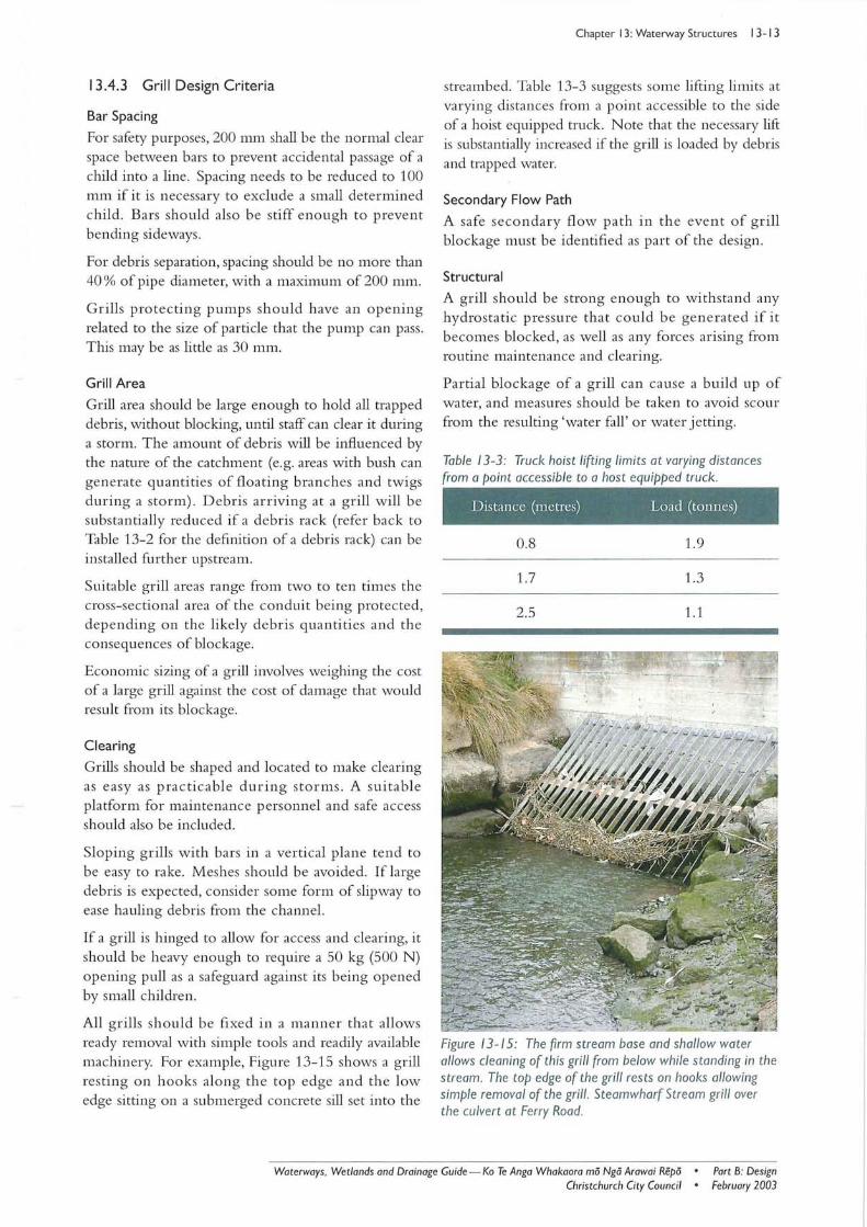
All grills should be fixed in a manner that allows ready removal with simple tools and readily available machinery. For example, Figure 13-15 shows a grill resting on hooks along the top edge and the low edge sitting on a submerged concrete sill set into the
Chapter 13: Waterway Structures 13-13
streambed. Table 13-3 suggests some lifting limits at varying distances from a point accessible to the side of a hoist equipped truck. Note that the necessary lift is substantially increased if the grill is loaded by debris and trapped water.
Secondary Flow Path
A safe secondary flow path in the event of grill blockage must be identified as part of the design.
Structural
A grill should be strong enough to withstand any hydrostatic pressure that could be generated if it becomes blocked, as well as any forces arising from routine maintenance and clearing.
Partial blockage of a grill can cause a build up of water, and measures should be taken to avoid scour from the resulting 'water fall' or water jetting.
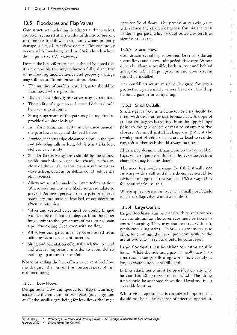
Table 13-3: Truck hoist li ft ing limits at varying distances from a point accessible to a host equipped truck. I
Distance (metres) Load (tonnes)
0.8 1.9
1.7 1.3
2.5 1.1
Figure 13- 15: The firm stream base and shallow water allows cleaning of this grill from below while standing in the stream. The top edge of the grill res ts on hooks allowing Simple removal of the grill. Steamwharf Stream grill over the culvert at Ferry Road.
Waterways, Wetlands and Drainage Guide-Ka Te Anga Whakaora mii Ngo Arawai Repii • Christchurch City Council •
Part B: Design February 2003
13-14 Chapter 13: Waterway Structures
13.5 Floodgates and Flap Valves Gate structures, including floodgates and flap valves, are often required at the outlet of drains to prevent or minimise backflows in situations where property damage is likely if backflow occurs. This commonly occurs with low-lying land in Christchurch where discharge is to a tidal waterway.
Despite the best efforts to date, it should be noted that it is not possible to always achieve a full seal and that some flooding inconvenience and property damage may still occur. To minimise this problem:
The number of outfalls requiring gates should be minimised where possible.
Back up secondary gates/valves may be required.
The ability of a gate to seal around debris should be taken into account.
Storage upstream of the gate may be required to provide for minor leakage.
Aim for a minimum 150 mm clearance beneath the gate lower edge and the bed below.
Provide generous edge clearance between the gate and side wingwalls, as long debris (e.g. sticks, logs, etc) can catch easily.
Smaller flap valve systems should be positioned within manholes or inspection chambers, that are clear of the outfall water margin where either wave action, current, or debris could reduce the effectiveness.
Allowance must be made for future sedimentation. Where sedimentation is likely to accumulate to prevent the free operation of the gate or valve, a secondary gate must be installed, or consideration given to pumping.
Valves and vertical gates must be double hinged with a slope of at least six degrees from the upper hinge point to the gate centre of mass to maintain a positive closing force, even with no flow.
All valves and gates must be constructed from saline resistant permanent materials.
Siting and orientation of outfalls, relative to wind and tide, is important in order to avoid debris building up around the outlet.
Notwithstanding the best efforts to prevent backflow, the designer shall assess the consequences of any malfunctioning.
13.5.1 Low Flows Design must allow unimpeded low flows. This may necessitate the provision of twin gates (one large, one small); the smaller gate being for low flows, the larger
gate for flood flows. The provision of twin gates will reduce the chance of debris fouling the seals of the larger gate, which would otherwise result in significant leakage.
13.5.2 Storm Flows Gate structures and flap valves must be reliable during storm flows and allow unimpeded discharge. Where debris build-up is possible, both in front and behind any gate, debris traps upstream and downstream should be installed.
The outfall structure must be designed for scour protection, particularly where head can build up behind a gate prior to opening.
13.5.3 Small Outfalls Smaller pipes (450 mm diameter or less) should be fitted with cast iron or cast bronze flaps. A slope of at least six degrees is required from the upper hinge point to the gate centre of mass to ensure positive closure. As small initial leakage can prevent the development of sufficient hydrostatic head to seal the flap, soft rubber seals should always be fitted.
Alternative designs, utilizing sinLple heavy rubber flaps, which operate within manholes or inspection chambers, may be considered.
The need to provide passage for fish is usually not an issue with small outfalls, although it would be advisable to approach the Parks and Waterways Unit for confirmation of this.
Where appearance is an issue, it is usually preferable to site the flap valve within a manhole.
13.5.4 Large Outfalls Larger floodgates can be made with treated timber, steel, or aluminium, however care must be taken to control warping. They may also be fitted with soft, synthetic sealing strips. Debris is a common cause of malfunction, and the use of protective grills, or the use of two gates in series should be considered.
Large floodgates can be either top hung or side hung. While the side hung gate is usually harder to construct, it can pass floating debris more readily, as long as there is adequate still depth.
Lifting attachments must be provided on any gate heavier than 50 kg or 600 mm in width. The lifting strap should be anchored above flood level and in an accessible location.
Whilst visual appearance is considered important, it should not be at the expense of effective operation.
Part B: Design February 2003
• Waterways, Wetlands and Drainage Guide-Ko Te Anga Whakaora rna Ngii Arawai Repa • Christchurch City Council
Close or inappropriate planting near any flood gate or flap valve structure is not encouraged if they could interfere with its effective operation.
13.5.5 Fish Passage
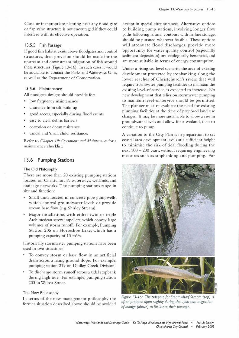
If good fish habitat exists above floodgates and control structures, then provision should be made for the upstream and downstream migration of fish around these structures (Figure 13-16). In such cases it would be advisable to contact the Parks and Waterways Unit, as well as the Department of Conservation.
13.5.6 Maintenance
All floodgate designs should provide for:
low frequency maintenance
clearance from silt build up
good access, especially during flood events
easy to clear debris barriers
corrosion or decay resistance
vandal and 'small child' resistance.
Refer to Chapter 19: Operatiolls alJd MaintellaIJce for a maintenance checklist.
13.6 Pumping Stations
The Old Philosophy
There are more than 20 existing pumping stations located on Christchurch's waterways, wetlands, and drainage networks . The pumping stations range in size and function :
Small units located in concrete pipe pumpwells, which control groundwater levels or provide stream base flow (e.g. Shirley Stream).
Major installations with either twin or triple Archimedean screw impellers, which convey large volumes of storm runoff. For example, Pumping Station 205 on Horseshoe Lake, which has a pumping capacity of 13 m3 / s.
Historically stormwater pumping stations have been used in two situations:
To convey storm or base flow in an artificial drain across a rising ground slope. For example, pumping station 219 on Dudley Creek Division.
To discharge storm runoff across a tidal stop bank during high tide. For example, pumping station 203 in Wairoa Street.
The New Philosophy
In terms of the new management philosophy the former situation described above should be avoided
Chapter 13: Waterway Structures 13-15
except in special circumstances. Alternative options to building pump stations, involving longer flow paths following natural contours with in-line storage, should be pursued wh erever feasible. These options will attenuate flood discharge s , provide more opportunity for water quality control (especially sediment deposition), are ecologically beneficial , and are more suitable in terms of energy consumption .
Under a rising sea level scenario, the area of existing development protected by stopbanking along the lower reaches of Christchurch 's rivers that will require stormwater pumping facilities to maintain the existing level-of-service, is expected to increase. No new development that relies on stormwater pumping to maintain level-of-service should be permitted. The planner must re-evaluate the need for existing pumping facilities at the time of proposed land use changes. It may be more sustainable to allow a rise in groundwater levels and allow for a wetland, than to continue to pump.
A variation to the City Plan is in preparation to set coastal area development levels at a sufficient height to minimise the risk of tidal flooding during the next 100 - 200 years, without requiring engineering measures such as stopbanking and pumping. For
Figure 13- /6 : The tidegate for Steamwharf Stream (top) is oft en propped open slightly during the upstream migration of inanga (above) to facili tate their passage.
Waterways, Wetlands and Drainage Guide-Ka Te Anga Whakaora rnii Ngii Arawai Repii • Port B: Design February 2003 Christchurch City Council •
13-16 Chapter 13: Waterway Structures
additional information refer to Christchurch City Council (2000a).
New pumping stations to protect existing low-lying areas should be installed as a last resort, only after all other options such as stormwater detention and house raising have been exhausted.
13.6.1 Design Considerations
When considering a stormwater pumping station, it is important that any possible adverse effects to nearby springs and waterways due to lowering groundwater levels be investigated and mitigated.
Christchurch stormwater stations are usually shallow and operate against low heads but can have relatively high flows. For this reason pumps tend to be quite large but with relatively low power consumption.
Superstructures are usually necessary to house motors and switchgear above ground and flood levels. These must not appear as plain utility features, but should merge with the landscape.
It will usually be found that an in sitll substructure is appropriate. However, submersible pumps in precast spun concrete pipe pumpwells may be suitable for small stations.
Usually pumps discharge to an outlet chamber, which discharges into gravity lines, and sometimes there will be a station bypass, fitted with a floodgate. It is useful to be able to seal off the separate pump chambers with stop logs for maintenance.
Stormwater pumping stations are deemed to be a lifeline facility that must have a high probability of remaining operational through and after an extreme event such as earthquake or storm. Refer to Sectioll 13.6.2: Lifeli/les Considerations.
Design Flow
Normally, pump stations should be designed for the drawoff from the contributory system required to achieve the appropriate level of service. Refer to Chapter 20: IllIlIIdatioll Des(\Z1I Pe!'forl/la/lce Sta/ldards.
Although it is not usual to provide duplication, it is advisable to have two or three pump units. This will allow the station to retain a reasonable capacity, even if one unit is out of action. Often, with multiple pumps, one pump can be sized to best suit the base flow conditions.
It should be noted that stormwater pumping stations are very seldom required to work at peak capacity, and half capacity would rarely be exceeded more than once per year.
Flotation
Structure buoyancy must be carefully checked so that a safe condition exists at all stages of construction and operation, including high flood levels.
The possibility of artesian conditions that give rise to water pressure higher than ground level should be investigated.
In buoyancy calculations, safety factors should be at least 1.1, excluding skin friction. At critical early condition and for the permanent condition they should be at least 1.4, including skin fi'iction, and 1.2 excluding skin friction.
13.6.2 Lifelines Considerations
The designer must consider how the pumping station structure and all system components will perform under each of the Engineering Lifelines (Centre for Advanced Engineering 1997) hazard scenarios and other related factors as outlined below.
Earthquake
The designer must consider and mitigate against the following earthquake factors:
deep soil bearing capacity
liquefaction of fine-grained soils
slope stability, especially where adjacent to a riverbank
horizontal earth pressures
slosh effects on the structure and attachments
flexible jointing of pipe connections, sufficient to cope with the predicted lateral and vertical displacements
secure fixture of cranes, switchgear, batteries, etc.
Flooding
The designer must consider and mitigate against the following flooding issues:
internal flooding due to power failure or inability to cope with inflows
external flood water level from a storm event or extreme sea level
water proofing the superstructure
water proofing the electrical system
setting all of the sensitive electrical and electronic equipment above the 100 year flood level.
Security of Power Supply
The designer must consider the following issues:
consequences of failure of power supply
• installation of a permanent emergency generator
Part B: Design February 2003
• Waterways, Wetlands and Drainage Guide-Ko Te Anga Whakaora mii Ngii Arawai Repii • Christchurch City Council
inclusion of a 3 phase socket for connection of an external generator.
Vandalism
Vandalism is likely at sites which are isolated or obscured. Thus exteriors, valve gear, etc, should be constructed to minimise potential damage.
Remote Monitoring
The need to incorporate a telemetry-based remote monitoring system will be assessed by the Parks and Waterways Unit. Such systems are essential on larger stations and other locations where the consequences of failure are significant.
If required the monitoring system must integrate with the current SCADA system.
13.6.3 Structural Design
Structural aspects of any pumping station design commences with the use of low stress levels for concrete and steel. This is customary practice for water retaining structures and should apply to the whole substructure. Higher resulting mass is useful for combating buoyancy. Design the superstructure in accordance with normal structural practice:
An additional sealing slab with a water stop, above the plug to prevent leaks. The sealing slab over the plug must resist full hydrostatic pressure by either adequate bonding to the plug, or by adequate bending strength.
Positive ties between the ground level slab and caisson walls to prevent slabs being forced off hydraulically.
Protecting concrete from external corrosive attack if aggressive groundwater is present.
Attention to metalwork anti-corrosion measures.
Grills
The inlet should be provided with adequate grills sufficient to prevent pump blockage or damage, but with a maximum bar spacing of 150 mm for safety reasons, and of sufficient strength to resist hydraulic pressure at full blockage.
Construction Aspects
While the caisson and plug technique has proved satisfactory, leaks can occur on curing the plug within the previously cured caisson, or within the plug itself. These can be minimised by:
dewatering and pouring the plug in the dry
pouring the plug underwater with 'tremie' pipes or concrete pumps.
Chapter 13: Waterway Structures 13-17
The tremie pipes must be socked and charged. The pipes must be positioned to cover the pour by vertical mOVelTlent only. One pipe would be adequate for a small submersible unit station, and three to five would be adequate for a drywell station. Controlled vertical movement and an adequate supply of concrete to the pipe are essential.
Special mix designs usually incorporating additives should be used for underwater pours.
A critical time in the sinking process occurs when the caisson is near the final level. Since sinking is carried out by over excavation, there is a risk of sinking the caisson too far. Movement can usually be arrested by internal ballasting (with water), but allowance in design should be made for some oversinking.
If the groundwater level needs to be lowered during the critical phase in construction of pumping out the caisson after curing the plug, then this must be clearly indicated in the associated specification, together with requirements for control.
13.6.4 Pumps and Drives
Stormwater pumps can be characterised as operating with high flows against low heads. Traditionally they have been of the vertical axial flow type. A more recent development is the Archimedean screw pump, consisting of a large diameter steel screw rotating slowly in a sloping concrete channel, giving a positive displacement action. These give good power efficiency for larger flows and lower heads.
When choosing between higher power efficiency and higher capital cost, it must be remembered that most stations operate at full capacity for only a few hours per year. If there is a small low capacity pump, it will operate much more often than a high capacity pump, and its power consumption will be relatively more important. One must also note the effect of peak power charges.
The power requirement for pumps is given by:
Q'Ih Power (kW) =
where Q = flow (m3/s)
'I = specific weight
= pg ~ 10 kN/m3 for water
h = head in metres
Eqn (13-1)
11 = pump efficiency (50 to 75 %)
Waterways. Wetlands and Drainage Guide-Ko Te Anga Whakaora mii Ngo Arawai Repii • Christchurch City Council •
Part B: Design February 2003
13-18 Chapter 13: Waterway Structures
Generally a low efficiency pump is preferable because higher internal clearances give greater durability and robustness, while the increase in electricity cost is generally minimal at the low pump duty typical of most stormwater stations.
Axial Flow Vertical Flood Pumps
Pumps of a given diameter can be operated at varying speeds, and with different impellers, and this varies the capacity and efficiency for a given head. The lift for Christchurch stormwater stations rarely exceeds two metres, which is usually lower than the head corresponding to maximum pump efficiency.
When choosing pumps it should be noted that a heavily loaded pump with low efficiency may require a larger motor, and may give a higher overall cost than a larger pump with a smaller motor.
Archimedean Screw Pumps
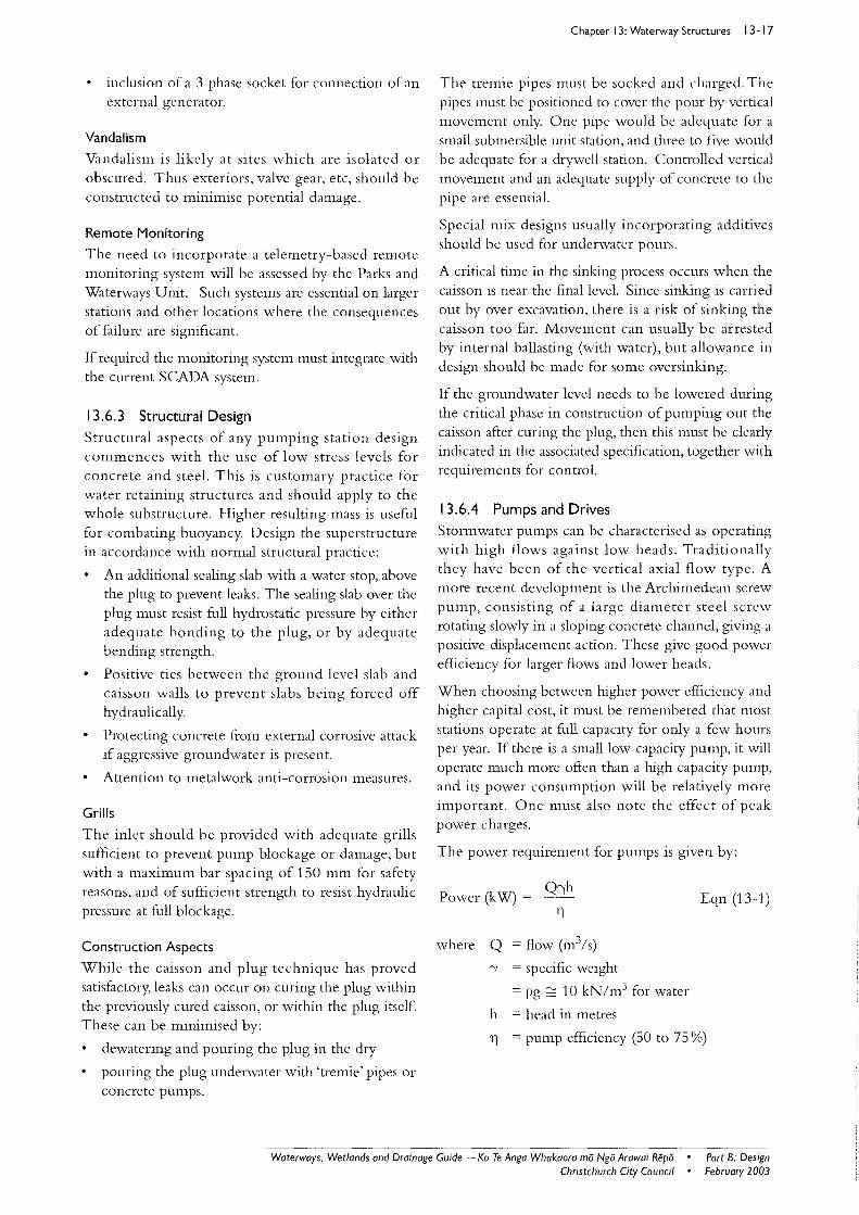
Typical operating data are as shown in Table 13-4.
Note that efficiency is typically 75 % with similar operating characteristics to that of a variable speed centrifugal pump.
The slope (a) of the screw is usually between 22° and 40° and the screw length (L) is approximately:
h L = --+ 0.7 x diameter (m111)
sin(a)
where h lift height (mm)
a slope of screw axis
Eqn (13-2)
Table 13-4: Discharge versus power for an archimedian screw pump.
300 12 0.15
600 72 1
1000 230 3
2000 1200 16
3000 3000 40
4000 5800 76
13.7 Stopbanks Stopbanks have been used to reduce the frequency of flooding in low-lying areas. Stopbanks are not an acceptable form of flood damage reduction for new urban development, which should always comply with the land and floor levels set by the Council, whether or not a stop bank exists.
A decision to use stop banks will be preceded by a very careful investigation including consultation with affected parties. A resource consent will be required from Environment Canterbury to divert natural water, as well as from the Christchurch City Council if the stopbank falls inside the distances stated in the waterway setback rules of the Proposed City Plan (Christchurch City Council 1999). The Department of Conservation's consent will be required in the Coastline Marine Area if works extend below mean high water spring (MHWS).
The designer should be aware of the disadvantages of stopbanks. These include:
loss of floodplain storage
loss of riparian environment
loss of views of a waterway and its margins
potential failure from damage and vandalism and geotechnical related causes such as piping, erosion, and foundation failure due to liquefaction under earthquake shaking.
In estuarine areas stop banks eventually finish up being a "hard edge" to an estuary, lagoon, or river, as natural processes of erosion and accretion are inhibited, causing ultimate loss of important wetlands. This effect is compounded under a rising sea level scenario. However, there may also be circumstances where stop banks can be used to protect and prolong the life of a wetland.
Sensitive design of the stop bank itself is essential. Design must harmonise with the landscape, natural processes, and local material. This is best achieved with an ecologist, engineer, and landscape architect working together. On-site "mock-ups" will assist in assessing visual effects and obtaining the feedback from local property owners.
13.8 Waterway Structural Lining Waterway structural lining is not discussed in this chapter. Refer to Chapter 12: Hfaterlllay Erosion Protection.
Part B: Design February 2003
• Waterways. Wetlands and Drainage Guide - Ko Te Anga Whakaora mii Ngo Arawai Repii • Christchurch City Council
I 3.9 Waterway Fences Fence location and design impact significantly on landscape, social, and ecological values of waterways and wetlands. They may also intelfere with drainage.
In residential areas a watenvay or wetland can become a landscape feature and visual asset to private property, to be enjoyed by the property occupants. This can be achieved by the following:
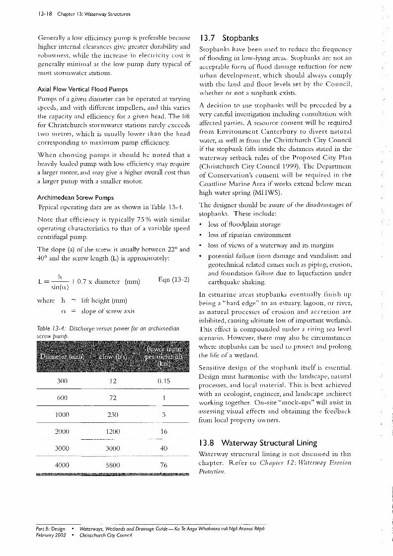
Having no fence between the waterway and the house, but instead integrating garden planting with that associated with the waterway (Figure 13-17).
Using suitable plants appropriately located to provide a soft attractive buffer between neighbours in order to provide privacy between neighbours. This applies either with or without a fence.
Avoiding high solid fences as they provide a haven for anti-social activities and a lost opportunity to add to the value of a residential property, both in financial and landscape terms.
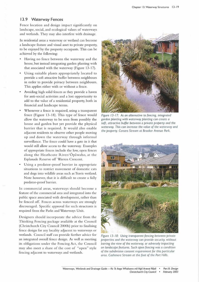
Whenever a fence is required, using a transparent fence (Figure 13-18) . This type of fence would allow the waterway to be seen from possibly the house and garden but yet provide the physical barrier that is required. It would also enable adjacent residents to observe other people moving up and down th e waterway through informal surveillance. The fence could have a gate in it that would still allow access to the waterway. Examples of appropriate fences include the low, open fences along the H ea th co te River/ Opawaho, at th e Esplanade Reserve off Warren Crescent.
Using a predator-proof barri er in appropriate situations to restrict movement of domestic cats and dogs into wildlife areas such as Travis wetland. Note however, that it is difficult to create a fully predator-proof barrier.
In commercial areas, waterways should become a feature of the commercial area and integrated into the public space associated with development, rather than be fenced off. Fences ac ross waterways are strongly discouraged. Specific approval for such structures is required from the Parks and Waterways Unit.
Designers should incorporate the advice from th e Thinking Fencing package available at the Council (Christchurch City Council 2000b) prior to finalising fence design for any locality adjacent to waterways or wetlands. Council staff can provide further advice for an integra ted overall fence design. As well as meeting its obligations under the Fencing Act, the Council may also meet a share of the cost of "open" style fencing adjacent to waterways and wetlands.
Chapter 13: Waterway Structures 13- 19
Figure 13-17: As an alternative to fencing, integrated garden planting with waterway planting can create a soft , attractive buffer between a private property and the waterway. This can increase the value of the waterway and the property. Corsers Stream at Brooker Avenue Park.
Figure 13-18: Using transparent fencing between private properties and the waterway can prOVide security, without barring the view of the waterway, or adversely impacting on landscape features. Such open fencing was a condition of the subdivision consent requirement for this particular area. Cashmere Stream at the foot of the Port Hills.
Waterways. Wetlands and Drainage Guide - Ko Te Anga Whakaora mo Ngo Arawai Repo • Port B: Design Christchurch City Council • February 2003

13-20 Chapter 13: Waterway Structures
13.10 References Boubee, J., Jowett, 1., Nichols, S. & Williams, E. 1999. Fish PassaRe at ClIllJerts: A RelJiell~ with Possible Soilltiolls for Nel/! Zealalld IlIdiRellolis Species. Department of Conservation, Wellington.
Boubee, J., Williams, E. & Richardson, J. 2000. Fish Passage Guidelines in the Auckland Region. Allckland Regiollal COllllcil Techllical Pllblicatioll No. 131. Auckland Regional Council, Auckland.
Building Industry Authority (BIA) 2002. Appro/Jed Dowl/lent for the New Zealand Bllilding Code, Safety frol/l Fallillg F4. Scenario Communications Ltd. (on behalf of the Building Industry Authority), Wellington.
Christchurch City Council 1999. City (~f
Christchllrch Cit)' Plall. The Proposed District Plall for the City (if Christchllrch. Christchurch City Council, Christchurch.
Christchurch City Council 2000a. Proposed T;(jriation to the City Plall, Variation 48: Floodillg Isslies ill C/nistcllllrch. Draft discussion document. Christchurch City Council, Christchurch.
Christchurch City Council 2000b. Thinking About Fencing. Information package. Christchurch City Council, Christchurch.
Centre for Advanced Engineering 1997. Risks and Realities: A Mlllti-disciplinary Approach to the Vttlllerability (if Lifelines to Natllral Hazards. Centre for Advanced Engineering, University of Canterbury, Christchurch.
Mitchell, C. P. 1990. Fish Passes for Native Fish: A Guide for Managers. New Zealalld Freshwater Fisheries l\1iscellalleolls Report No. 45. Freshwater Fisheries Centre, MAF Fisheries, Rotorua.
Transit New Zealand 1994. BridJ?e MallllalSPIMI014: May 1994. Transit New Zealand, Wellington.
Part B: Design • Waterways. Wetlands and Drainage Guide- Ko Te Anga Whakaora mii Ngii Arawai Repii February 2003 • Christchurch City Council