Watcom FORTRAN 77 User’s Guide
344
Watcom FORTRAN 77 User’s Guide Edition 11.0c
Transcript of Watcom FORTRAN 77 User’s Guide

Watcom FORTRAN 77
User’s Guide
Edition 11.0c

Notice of CopyrightCopyright 2000 Sybase, Inc. and its subsidiaries. All rights reserved.
No part of this publication may be reproduced, transmitted, or translated in any form or byany means, electronic, mechanical, manual, optical, or otherwise, without the prior writtenpermission of Sybase, Inc. and its subsidiaries.
Printed in U.S.A.
ii

PrefaceThe Watcom FORTRAN 77 Optimizing Compiler (Watcom F77) is an implementation of theAmerican National Standard programming language FORTRAN, ANSI X3.9-1978,commonly referred to as FORTRAN 77. The language level supported by this compilerincludes the full language definition as well as significant extensions to the language.Watcom F77 evolved out of the demands of our users for a companion optimizing compiler toWatcom’s WATFOR-77 "load-and-go" compiler.
The "load-and-go" approach to processing FORTRAN programs emphasizes fast compilationrates and quick placement into execution of FORTRAN applications. This type of compiler isused heavily during the debugging phase of the application. At this stage of applicationdevelopment, the "load-and-go" compiler optimizes the programmer’s time ... not theprogram’s time. However, once parts of the application have been thoroughly debugged, itmay be advantageous to turn to a compiler which will optimize the execution time of theexecutable code.
Watcom F77 is a highly optimizing compiler based on the code generation technology thatwas developed for Watcom’s highly-praised C and C++ optimizing compilers. Watcom F77is a traditional compiler in the sense that it creates object files which must be linked into anexecutable program.
The Watcom FORTRAN 77 User’s Guide describes how to use Watcom FORTRAN 77 withDOS, OS/2, Windows 3.x, Windows NT, and Windows 95.
AcknowledgementsThis book was produced with the Watcom GML electronic publishing system, a software tooldeveloped by WATCOM. In this system, writers use an ASCII text editor to create sourcefiles containing text annotated with tags. These tags label the structural elements of thedocument, such as chapters, sections, paragraphs, and lists. The Watcom GML software,which runs on a variety of operating systems, interprets the tags to format the text into a formsuch as you see here. Writers can produce output for a variety of printers, including laserprinters, using separately specified layout directives for such things as font selection, columnwidth and height, number of columns, etc. The result is type-set quality copy containingintegrated text and graphics.
iii
We would like to thank IMSL of Houston, Texas for providing us with copies of theirMathematics and Statistics libraries. The IMSL Math Library is a collection of subprogramsfor mathematical problem solving and the Statistics Library is a collection of subprograms forstatistical analysis. The self test procedures provided with these libraries proved to be animmense help in testing Watcom F77 on the personal computer.
We also used the "FORTRAN Compiler Validation System, Version 2.0" to test theconformance of Watcom F77 with the full FORTRAN 77 language standard. This package isprovided by the National Technical Information Service of the U.S. Department ofCommerce in Springfield, Virginia. The validation system was developed by the FederalSoftware Testing Center.
If you find problems in the documentation or have some good suggestions, we would like tohear from you.
September, 2000.
Trademarks Used in this ManualAutoCAD Development System is a trademark of Autodesk, Inc.
DOS/4G is a trademark of Tenberry Software, Inc.
IBM Developer’s WorkFrame/2, Presentation Manager, and OS/2 are trademarks ofInternational Business Machines Corp. IBM is a registered trademark of InternationalBusiness Machines Corp.
Intel and Pentium are registered trademarks of Intel Corp.
Microsoft, Windows and Windows 95 are registered trademarks of Microsoft Corp. WindowsNT is a trademark of Microsoft Corp.
NetWare, NetWare 386, and Novell are registered trademarks of Novell, Inc.
Phar Lap, 286|DOS-Extender, and 386|DOS-Extender are trademarks of Phar Lap Software,Inc.
QNX is a trademark of QNX Software Systems Ltd.
WATCOM is a trademark of Sybase, Inc. and its subsidiaries.
iv

Table of Contents
Watcom FORTRAN 77 User’s Guide ....................................................................................... 1
1 About This Manual ..................................................................................................... 3
2 Watcom FORTRAN 77 Compiler Options ................................................................. 52.1 Watcom F77 Options Summary ................................................................... 52.2 Compiler Options ......................................................................................... 9
3 The Watcom FORTRAN 77 Compiler ....................................................................... 293.1 Watcom FORTRAN 77 Command Line Format .......................................... 293.2 WFC/WFC386 Environment Variables ........................................................ 303.3 Watcom FORTRAN 77 Command Line Examples ..................................... 313.4 Compiler Diagnostics ................................................................................... 323.5 Watcom FORTRAN 77 INCLUDE File Processing .................................... 35
4 The Watcom FORTRAN 77 Libraries ........................................................................ 374.1 Watcom FORTRAN 77 80x87 Emulator Libraries ...................................... 404.2 The "NO87" Environment Variable ............................................................. 41
5 Watcom FORTRAN 77 Compiler Directives ............................................................. 435.1 Introduction .................................................................................................. 435.2 The EJECT Compiler Directive .................................................................... 445.3 The INCLUDE Compiler Directive .............................................................. 445.4 The PRAGMA Compiler Directive .............................................................. 465.5 The DEFINE Compiler Directive ................................................................. 465.6 The UNDEFINE Compiler Directive ........................................................... 465.7 The IFDEF, IFNDEF and ENDIF Compiler Directive ................................ 475.8 The ELSE Compiler Directive ...................................................................... 485.9 The ELSEIFDEF and ELSEIFNDEF Compiler Directive ........................... 485.10 Debugging statements ("D" in Column 1) .................................................. 495.11 General Notes About Compiler Directives ................................................. 49
6 Watcom FORTRAN 77 File Handling ....................................................................... 516.1 Record Access .............................................................................................. 516.2 Record Format .............................................................................................. 52
6.2.1 FORMATTED Records ................................................................. 526.2.2 UNFORMATTED Records ............................................................ 526.2.3 Files with no Record Structure ....................................................... 54
6.3 Attributes of Files ......................................................................................... 546.3.1 Record Type ................................................................................... 556.3.2 Record Size .................................................................................... 566.3.3 Print File Attributes ........................................................................ 56
v

Table of Contents
6.3.4 Input/Output Buffer Size ................................................................ 576.3.5 File Sharing .................................................................................... 58
6.4 File Names in the FAT File System ............................................................. 596.4.1 Special DOS Device Names ........................................................... 606.4.2 Examples of FAT File Specifications ............................................ 60
6.5 File Names in the High Performance File System ........................................ 616.5.1 Special OS/2 Device Names .......................................................... 626.5.2 Examples of HPFS File Specifications .......................................... 62
6.6 Establishing Connections Between Units and Files ..................................... 636.7 A Preconnection Tutorial .............................................................................. 676.8 Logical File Name Support ........................................................................... 696.9 Terminal or Console Device Support ........................................................... 736.10 Printer Device Support ............................................................................... 756.11 Serial Device Support ................................................................................. 756.12 File Handling Defaults ................................................................................ 76
7 The Watcom F77 Subprogram Library ....................................................................... 797.1 Subroutine FEXIT ........................................................................................ 797.2 INTEGER Function FGETCMD .................................................................. 797.3 INTEGER Function FGETENV ................................................................... 807.4 INTEGER Function FILESIZE .................................................................... 817.5 Subroutine FINTR ........................................................................................ 827.6 INTEGER Function FLUSHUNIT ............................................................... 847.7 INTEGER Function FNEXTRECL .............................................................. 857.8 INTEGER Function FSIGNAL .................................................................... 877.9 INTEGER Function FSPAWN ..................................................................... 887.10 INTEGER Function FSYSTEM ................................................................. 897.11 Subroutine FTRACEBACK ....................................................................... 907.12 Subroutine GETDAT .................................................................................. 917.13 Subroutine GETTIM ................................................................................... 927.14 INTEGER Function GROWHANDLES .................................................... 937.15 Functions IARGC and IGETARG .............................................................. 937.16 Math Error Functions .................................................................................. 947.17 INTEGER Function SEEKUNIT ............................................................... 967.18 INTEGER Function SETJMP/Subroutine LONGJMP .............................. 977.19 INTEGER Function SETSYSHANDLE .................................................... 987.20 INTEGER*2 Function SYSHANDLE ....................................................... 997.21 REAL Function URAND ........................................................................... 1007.22 Default Windowing Functions .................................................................... 101
7.22.1 dwfDeleteOnClose ....................................................................... 1027.22.2 dwfSetAboutDlg .......................................................................... 1027.22.3 dwfSetAppTitle ............................................................................ 103
vi

Table of Contents
7.22.4 dwfSetConTitle ............................................................................ 1047.22.5 dwfShutDown .............................................................................. 1057.22.6 dwfYield ....................................................................................... 106
8 Data Representation On x86-based Platforms ............................................................ 1098.1 LOGICAL*1 Data Type ............................................................................... 1098.2 LOGICAL and LOGICAL*4 Data Types .................................................... 1108.3 INTEGER*1 Data Type ............................................................................... 1108.4 INTEGER*2 Data Type ............................................................................... 1108.5 INTEGER and INTEGER*4 Data Types ..................................................... 1108.6 REAL and REAL*4 Data Types .................................................................. 1108.7 DOUBLE PRECISION and REAL*8 Data Types ....................................... 1118.8 COMPLEX, COMPLEX*8, and DOUBLE COMPLEX Data Types .......... 1138.9 COMPLEX*16 Data Type ........................................................................... 1138.10 CHARACTER Data Type .......................................................................... 1138.11 Storage Organization of Data Types .......................................................... 1148.12 Floating-point Accuracy On x86-based Platforms ..................................... 1158.13 Floating-point Exceptions On x86-based Platforms ................................... 1168.14 Compiler Options Relating to Floating-point ............................................. 1208.15 Floating-point Exception Handling ............................................................ 122
16-bit Topics .............................................................................................................................. 125
9 16-bit Memory Models ............................................................................................... 1279.1 Introduction .................................................................................................. 1279.2 16-bit Code Models ...................................................................................... 1279.3 16-bit Data Models ....................................................................................... 1279.4 Summary of 16-bit Memory Models ............................................................ 1289.5 Mixed 16-bit Memory Model ....................................................................... 1299.6 Linking Applications for the Various 16-bit Memory Models ..................... 1299.7 Memory Layout ............................................................................................ 130
10 16-bit Assembly Language Considerations .............................................................. 13110.1 Introduction ................................................................................................ 13110.2 Calling Conventions ................................................................................... 131
10.2.1 Processing Function Return Values with no 80x87 ..................... 13310.2.2 Processing Function Return Values Using an 80x87 ................... 13410.2.3 Processing Alternate Returns ....................................................... 13410.2.4 Alternate Method of Passing Character Arguments ..................... 134
10.2.4.1 Character Functions ....................................................... 13510.3 Memory Layout .......................................................................................... 135
vii
Table of Contents
10.4 Writing Assembly Language Subprograms ................................................ 13610.4.1 Returning Values from Assembly Language Functions .............. 140
11 16-bit Pragmas .......................................................................................................... 14711.1 Introduction ................................................................................................ 14711.2 Using Pragmas to Specify Default Libraries .............................................. 14811.3 Auxiliary Pragmas ...................................................................................... 149
11.3.1 Specifying Symbol Attributes ...................................................... 14911.3.2 Alias Names ................................................................................. 15011.3.3 Predefined Aliases ........................................................................ 151
11.3.3.1 Predefined "__cdecl" Alias ............................................ 15211.3.3.2 Predefined "__pascal" Alias .......................................... 152
11.3.4 Alternate Names for Symbols ...................................................... 15311.3.5 Describing Calling Information ................................................... 154
11.3.5.1 Loading Data Segment Register .................................... 15611.3.5.2 Defining Exported Symbols in Dynamic Link
Libraries ......................................................................... 15611.3.5.3 Defining Windows Callback Functions ......................... 157
11.3.6 Describing Argument Information ............................................... 15711.3.6.1 Passing Arguments to non-FORTRAN Subprograms ... 15811.3.6.2 Passing Arguments in Registers .................................... 16111.3.6.3 Forcing Arguments into Specific Registers ................... 16411.3.6.4 Passing Arguments to In-Line Subprograms ................. 16511.3.6.5 Removing Arguments from the Stack ........................... 16611.3.6.6 Passing Arguments in Reverse Order ............................ 167
11.3.7 Describing Subprogram Return Information ............................... 16711.3.7.1 Returning Subprogram Values in Registers ................... 16811.3.7.2 Returning Structures and Complex Numbers ................ 16911.3.7.3 Returning Floating-Point Data ....................................... 171
11.3.8 A Subprogram that Never Returns ............................................... 17211.3.9 Describing How Subprograms Use Variables in Common .......... 17311.3.10 Describing the Registers Modified by a Subprogram ................ 17711.3.11 Auxiliary Pragmas and the 80x87 .............................................. 178
11.3.11.1 Using the 80x87 to Pass Arguments ............................ 17911.3.11.2 Using the 80x87 to Return Subprogram Values .......... 18211.3.11.3 Preserving 80x87 Floating-Point Registers Across
Calls ............................................................................. 182
32-bit Topics .............................................................................................................................. 185
12 32-bit Memory Models ............................................................................................. 187
viii
Table of Contents
12.1 Introduction ................................................................................................ 18712.2 32-bit Code Models .................................................................................... 18712.3 32-bit Data Models ..................................................................................... 18812.4 Summary of 32-bit Memory Models .......................................................... 18812.5 Flat Memory Model .................................................................................... 18912.6 Mixed 32-bit Memory Model ..................................................................... 18912.7 Linking Applications for the Various 32-bit Memory Models ................... 19012.8 Memory Layout .......................................................................................... 190
13 32-bit Assembly Language Considerations .............................................................. 19313.1 Introduction ................................................................................................ 19313.2 Calling Conventions ................................................................................... 193
13.2.1 Stack-Based Calling Convention ................................................. 19413.2.2 Processing Function Return Values with no 80x87 ..................... 19513.2.3 Processing Function Return Values Using an 80x87 ................... 19613.2.4 Processing Alternate Returns ....................................................... 19613.2.5 Alternate Method of Passing Character Arguments ..................... 196
13.2.5.1 Character Functions ....................................................... 19713.3 Memory Layout .......................................................................................... 19813.4 Writing Assembly Language Subprograms ................................................ 199
13.4.1 Using the Stack-Based Calling Convention ................................. 20113.4.2 Returning Values from Assembly Language Functions .............. 204
14 32-bit Pragmas .......................................................................................................... 21114.1 Introduction ................................................................................................ 21114.2 Using Pragmas to Specify Default Libraries .............................................. 21214.3 Auxiliary Pragmas ...................................................................................... 213
14.3.1 Specifying Symbol Attributes ...................................................... 21314.3.2 Alias Names ................................................................................. 21414.3.3 Predefined Aliases ........................................................................ 215
14.3.3.1 Predefined "__cdecl" Alias ............................................ 21614.3.3.2 Predefined "__pascal" Alias .......................................... 21614.3.3.3 Predefined "__stdcall" Alias .......................................... 21714.3.3.4 Predefined "__syscall" Alias ......................................... 218
14.3.4 Alternate Names for Symbols ...................................................... 21814.3.5 Describing Calling Information ................................................... 219
14.3.5.1 Loading Data Segment Register .................................... 22114.3.5.2 Defining Exported Symbols in Dynamic Link
Libraries ......................................................................... 22214.3.6 Describing Argument Information ............................................... 222
14.3.6.1 Passing Arguments to non-FORTRAN Subprograms ... 22314.3.6.2 Passing Arguments in Registers .................................... 226
ix
Table of Contents
14.3.6.3 Forcing Arguments into Specific Registers ................... 22914.3.6.4 Passing Arguments to In-Line Subprograms ................. 23014.3.6.5 Removing Arguments from the Stack ........................... 23114.3.6.6 Passing Arguments in Reverse Order ............................ 232
14.3.7 Describing Subprogram Return Information ............................... 23314.3.7.1 Returning Subprogram Values in Registers ................... 23314.3.7.2 Returning Structures and Complex Numbers ................ 23514.3.7.3 Returning Floating-Point Data ....................................... 236
14.3.8 A Subprogram that Never Returns ............................................... 23714.3.9 Describing How Subprograms Use Variables in Common .......... 23814.3.10 Describing the Registers Modified by a Subprogram ................ 24314.3.11 Auxiliary Pragmas and the 80x87 .............................................. 245
14.3.11.1 Using the 80x87 to Pass Arguments ............................ 24514.3.11.2 Using the 80x87 to Return Subprogram Values .......... 24914.3.11.3 Preserving 80x87 Floating-Point Registers Across
Calls ............................................................................. 249
Appendices ................................................................................................................................ 251
A. Use of Environment Variables .................................................................................. 253A.1 FINCLUDE .................................................................................................. 253A.2 LIB ............................................................................................................... 253A.3 LIBDOS ....................................................................................................... 254A.4 LIBWIN ....................................................................................................... 254A.5 LIBOS2 ........................................................................................................ 254A.6 LIBPHAR .................................................................................................... 255A.7 NO87 ............................................................................................................ 255A.8 PATH ........................................................................................................... 256A.9 TMP ............................................................................................................. 257A.10 WATCOM ................................................................................................. 257A.11 WCL .......................................................................................................... 257A.12 WCL386 .................................................................................................... 258A.13 WCGMEMORY ........................................................................................ 258A.14 WD ............................................................................................................. 259A.15 WDW ......................................................................................................... 260A.16 WFC ........................................................................................................... 260A.17 WFC386 ..................................................................................................... 261A.18 WFL ........................................................................................................... 261A.19 WFL386 ..................................................................................................... 262A.20 WLANG .................................................................................................... 262
x

Table of Contents
B. Watcom F77 Diagnostic Messages ........................................................................... 265
xi

xii
Watcom FORTRAN 77 User’sGuide

Watcom FORTRAN 77 User’s Guide
2

1 About This Manual
This manual contains the following chapters:
Chapter 1 — "About This Manual".
This chapter provides an overview of the contents of this guide.
Chapter 2 — "Watcom FORTRAN 77 Compiler Options" on page 5.
This chapter also provides a summary and reference section for the validcompiler options.
Chapter 3 — "The Watcom FORTRAN 77 Compiler" on page 29.
This chapter describes how to compile an application from the command line,describes compiler environment variables, provides examples of command lineuse of the compiler, and and describes compiler diagnostics.
Chapter 4 — "The Watcom FORTRAN 77 Libraries" on page 37.
This chapter describes the Watcom FORTRAN 77 run-time libraries.
Chapter 5 — "Watcom FORTRAN 77 Compiler Directives" on page 43.
This chapter describes compiler directives including INCLUDE file processing.
Chapter 6 — "Watcom FORTRAN 77 File Handling" on page 51.
This chapter describes run-time file handling.
Chapter 7 — "The Watcom F77 Subprogram Library" on page 79.
This chapter describes subprograms available for special operations.
Chapter 8 — "16-bit Memory Models" on page 127.
This chapter describes the Watcom FORTRAN 77 memory models (includingcode and data models), the tiny memory model, the mixed memory model,
About This Manual 3

Watcom FORTRAN 77 User’s Guide
linking applications for the various memory models, creating a tiny memorymodel application, and memory layout in an executable.
Chapter 9 — "16-bit Assembly Language Considerations" on page 131.
This chapter describes issues relating to 16-bit interfacing such as parameterpassing conventions.
Chapter 10 — "16-bit Pragmas" on page 147.
This chapter describes the use of pragmas with the 16-bit compilers.
Chapter 11 — "32-bit Memory Models" on page 187.
This chapter describes the Watcom FORTRAN 77 memory models (includingcode and data models), the flat memory model, the mixed memory model,linking applications for the various memory models, and memory layout in anexecutable.
Chapter 12 — "32-bit Assembly Language Considerations" on page 193.
This chapter describes issues relating to 32-bit interfacing such as parameterpassing conventions.
Chapter 13 — "32-bit Pragmas" on page 211.
This chapter describes the use of pragmas with the 32-bit compilers.
Appendix A. — "Use of Environment Variables" on page 253.
This appendix describes all the environment variables used by the compilers andrelated tools.
Appendix B. — "Watcom F77 Diagnostic Messages" on page 265.
This appendix lists all of the Watcom F77 diagnostic messages with anexplanation for each.
4 About This Manual
2 Watcom FORTRAN 77 Compiler Options
Source files can be compiled using either the IDE, command-line compilers or IBMWorkFrame/2. This chapter describes all the compiler options that are available.
For information about compiling applications from the IDE, see the Watcom Graphical ToolsUser’s Guide.
For information about compiling applications from the command line, see the chapter entitled"The Watcom FORTRAN 77 Compiler" on page 29.
For information about creating applications using IBM WorkFrame/2, refer to IBM’s OS/2Programming Guide for more information.
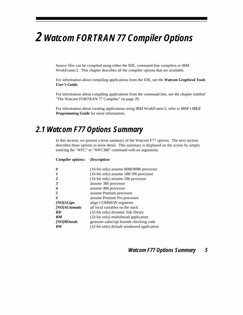
2.1 Watcom F77 Options SummaryIn this section, we present a terse summary of the Watcom F77 options. The next sectiondescribes these options in more detail. This summary is displayed on the screen by simplyentering the "WFC" or "WFC386" command with no arguments.
Compiler options: Description:
0 (16-bit only) assume 8088/8086 processor1 (16-bit only) assume 188/186 processor2 (16-bit only) assume 286 processor3 assume 386 processor4 assume 486 processor5 assume Pentium processor6 assume Pentium Pro processor[NO]ALign align COMMON segments[NO]AUtomatic all local variables on the stackBD (32-bit only) dynamic link libraryBM (32-bit only) multithread application[NO]BOunds generate subscript bounds checking codeBW (32-bit only) default windowed application
Watcom F77 Options Summary 5
Watcom FORTRAN 77 User’s Guide
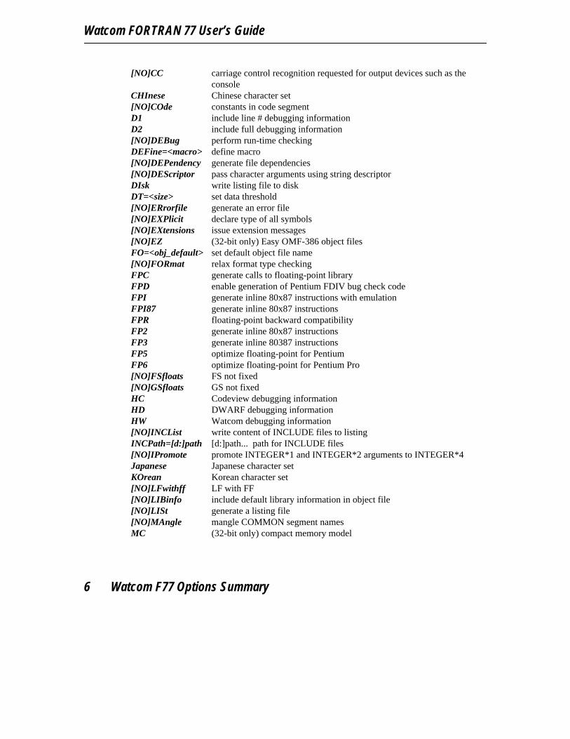
[NO]CC carriage control recognition requested for output devices such as theconsole
CHInese Chinese character set[NO]COde constants in code segmentD1 include line # debugging informationD2 include full debugging information[NO]DEBug perform run-time checkingDEFine=<macro> define macro[NO]DEPendency generate file dependencies[NO]DEScriptor pass character arguments using string descriptorDIsk write listing file to diskDT=<size> set data threshold[NO]ERrorfile generate an error file[NO]EXPlicit declare type of all symbols[NO]EXtensions issue extension messages[NO]EZ (32-bit only) Easy OMF-386 object filesFO=<obj_default> set default object file name[NO]FORmat relax format type checkingFPC generate calls to floating-point libraryFPD enable generation of Pentium FDIV bug check codeFPI generate inline 80x87 instructions with emulationFPI87 generate inline 80x87 instructionsFPR floating-point backward compatibilityFP2 generate inline 80x87 instructionsFP3 generate inline 80387 instructionsFP5 optimize floating-point for PentiumFP6 optimize floating-point for Pentium Pro[NO]FSfloats FS not fixed[NO]GSfloats GS not fixedHC Codeview debugging informationHD DWARF debugging informationHW Watcom debugging information[NO]INCList write content of INCLUDE files to listingINCPath=[d:]path [d:]path... path for INCLUDE files[NO]IPromote promote INTEGER*1 and INTEGER*2 arguments to INTEGER*4Japanese Japanese character setKOrean Korean character set[NO]LFwithff LF with FF[NO]LIBinfo include default library information in object file[NO]LISt generate a listing file[NO]MAngle mangle COMMON segment namesMC (32-bit only) compact memory model
6 Watcom F77 Options Summary
Watcom FORTRAN 77 Compiler Options
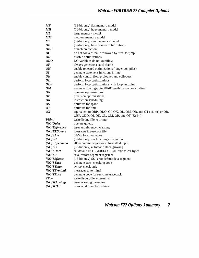
MF (32-bit only) flat memory modelMH (16-bit only) huge memory modelML large memory modelMM medium memory modelMS (32-bit only) small memory modelOB (32-bit only) base pointer optimizationsOBP branch predictionOC do not convert "call" followed by "ret" to "jmp"OD disable optimizationsODO DO-variables do not overflowOF always generate a stack frameOH enable repeated optimizations (longer compiles)OI generate statement functions in-lineOK enable control flow prologues and epiloguesOL perform loop optimizationsOL+ perform loop optimizations with loop unrollingOM generate floating-point 80x87 math instructions in-lineON numeric optimizationsOP precision optimizationsOR instruction schedulingOS optimize for spaceOT optimize for timeOX equivalent to OBP, ODO, OI, OK, OL, OM, OR, and OT (16-bit) or OB,
OBP, ODO, OI, OK, OL, OM, OR, and OT (32-bit)PRint write listing file to printer[NO]Quiet operate quietly[NO]Reference issue unreferenced warning[NO]RESource messages in resource file[NO]SAve SAVE local variables[NO]SC (32-bit only) stack calling convention[NO]SEpcomma allow comma separator in formatted input[NO]SG (32-bit only) automatic stack growing[NO]SHort set default INTEGER/LOGICAL size to 2/1 bytes[NO]SR save/restore segment registers[NO]SSfloats (16-bit only) SS is not default data segment[NO]STack generate stack checking code[NO]SYntax syntax check only[NO]TErminal messages to terminal[NO]TRace generate code for run-time tracebackTYpe write listing file to terminal[NO]WArnings issue warning messages[NO]WILd relax wild branch checking
Watcom F77 Options Summary 7

Watcom FORTRAN 77 User’s Guide
[NO]WIndows (16-bit only) compile code for Windows[NO]XFloat extend floating-point precision[NO]XLine extend line length to 132
A summary of the option defaults follows:
0 16-bit only5 32-bit onlyALignNOAUtomaticNOBOundsNOCCNOCOdeNODEBugDEPendencyDEScriptorDT=256ERrorfileNOEXPlicitNOEXtensionsNOEZ 32-bit onlyNOFORmatFPIFP2 16-bit onlyFP3 32-bit onlyNOFPDFSfloats all but flat memory modelNOFSfloats flat memory model onlyGSfloatsNOINCListNOIPromoteNOLFwithffLIBinfoNOLIStNOMAngleML 16-bit onlyMF 32-bit onlyNOQuietReferenceNORESourceNOSAveNOSC 32-bit only
8 Watcom F77 Options Summary

Watcom FORTRAN 77 Compiler Options
NOSEpcommaNOSG 32-bit onlyNOSHortNOSRNOSSfloats 16-bit onlyNOSTackNOSYntaxTErminalNOTRaceWArningsNOWILdNOWIndows 16-bit onlyNOXFloatNOXLine
2.2 Compiler OptionsCompiler options may be entered in one of two places. They may be included in the optionslist of the command line or they may be included as comments of the form "C$option","c$option", or "*$option" in the source input stream. The compiler recognizes these specialcomments as compiler directives.
Some options may only be specified in the options list of the command line. Unless otherwisestated, an option can appear on the command line only. We also indicate what the default isfor an option or group of options.
When specifying options in the source file, it is possible to specify more than one option on aline. For example, the following source line tells Watcom F77 to not issue any warning orextension messages.
Example:*$nowarn noext
Note that only the first option must contain the "*$", "C$", or "c$" prefix.
Short forms are indicated by upper case letters.
Compiler Options 9
Watcom FORTRAN 77 User’s Guide
Option: Description:
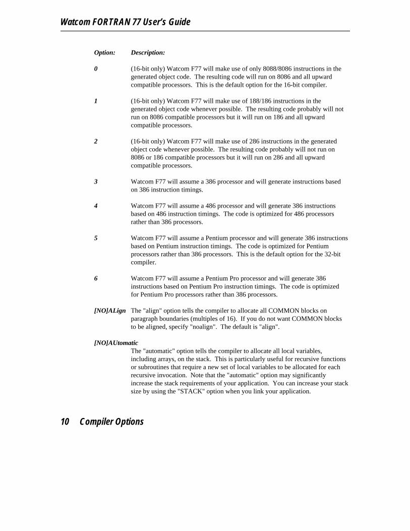
0 (16-bit only) Watcom F77 will make use of only 8088/8086 instructions in thegenerated object code. The resulting code will run on 8086 and all upwardcompatible processors. This is the default option for the 16-bit compiler.
1 (16-bit only) Watcom F77 will make use of 188/186 instructions in thegenerated object code whenever possible. The resulting code probably will notrun on 8086 compatible processors but it will run on 186 and all upwardcompatible processors.
2 (16-bit only) Watcom F77 will make use of 286 instructions in the generatedobject code whenever possible. The resulting code probably will not run on8086 or 186 compatible processors but it will run on 286 and all upwardcompatible processors.
3 Watcom F77 will assume a 386 processor and will generate instructions basedon 386 instruction timings.
4 Watcom F77 will assume a 486 processor and will generate 386 instructionsbased on 486 instruction timings. The code is optimized for 486 processorsrather than 386 processors.
5 Watcom F77 will assume a Pentium processor and will generate 386 instructionsbased on Pentium instruction timings. The code is optimized for Pentiumprocessors rather than 386 processors. This is the default option for the 32-bitcompiler.
6 Watcom F77 will assume a Pentium Pro processor and will generate 386instructions based on Pentium Pro instruction timings. The code is optimizedfor Pentium Pro processors rather than 386 processors.
[NO]ALign The "align" option tells the compiler to allocate all COMMON blocks onparagraph boundaries (multiples of 16). If you do not want COMMON blocksto be aligned, specify "noalign". The default is "align".
[NO]AUtomaticThe "automatic" option tells the compiler to allocate all local variables,including arrays, on the stack. This is particularly useful for recursive functionsor subroutines that require a new set of local variables to be allocated for eachrecursive invocation. Note that the "automatic" option may significantlyincrease the stack requirements of your application. You can increase your stacksize by using the "STACK" option when you link your application.
10 Compiler Options
Watcom FORTRAN 77 Compiler Options
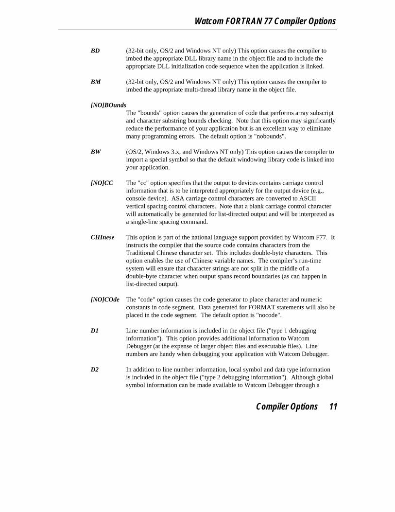
BD (32-bit only, OS/2 and Windows NT only) This option causes the compiler toimbed the appropriate DLL library name in the object file and to include theappropriate DLL initialization code sequence when the application is linked.
BM (32-bit only, OS/2 and Windows NT only) This option causes the compiler toimbed the appropriate multi-thread library name in the object file.
[NO]BOundsThe "bounds" option causes the generation of code that performs array subscriptand character substring bounds checking. Note that this option may significantlyreduce the performance of your application but is an excellent way to eliminatemany programming errors. The default option is "nobounds".
BW (OS/2, Windows 3.x, and Windows NT only) This option causes the compiler toimport a special symbol so that the default windowing library code is linked intoyour application.
[NO]CC The "cc" option specifies that the output to devices contains carriage controlinformation that is to be interpreted appropriately for the output device (e.g.,console device). ASA carriage control characters are converted to ASCIIvertical spacing control characters. Note that a blank carriage control characterwill automatically be generated for list-directed output and will be interpreted asa single-line spacing command.
CHInese This option is part of the national language support provided by Watcom F77. Itinstructs the compiler that the source code contains characters from theTraditional Chinese character set. This includes double-byte characters. Thisoption enables the use of Chinese variable names. The compiler’s run-timesystem will ensure that character strings are not split in the middle of adouble-byte character when output spans record boundaries (as can happen inlist-directed output).
[NO]COde The "code" option causes the code generator to place character and numericconstants in code segment. Data generated for FORMAT statements will also beplaced in the code segment. The default option is "nocode".
D1 Line number information is included in the object file ("type 1 debugginginformation"). This option provides additional information to WatcomDebugger (at the expense of larger object files and executable files). Linenumbers are handy when debugging your application with Watcom Debugger.
D2 In addition to line number information, local symbol and data type informationis included in the object file ("type 2 debugging information"). Although globalsymbol information can be made available to Watcom Debugger through a
Compiler Options 11

Watcom FORTRAN 77 User’s Guide
Watcom Linker option, local symbol and typing information must be requestedwhen the source file is compiled. This option provides additional information toWatcom Debugger (at the expense of larger object files and executable files).However, it will make the debugging chore somewhat easier.
[NO]DEBugThe "debug" option causes the generation of run-time checking code. Thisincludes subscript and substring bounds checking as well as code that allows arun-time traceback to be issued when an error occurs. The default option is"nodebug".
DEFine=<macro>This option is equivalent to specifying the following "define" compiler directive.
*$define <macro>
The macro specified by the "define" option or compiler directive becomesdefined. The definition status of the specified macro can be checked using the"ifdef", "ifndef", "elseifdef" or "elseifndef" compiler directives. This allowssource code to be conditionally compiled depending on the definition status ofthe macro.
The macro i86 is a special macro that is defined by the compiler andidentifies the target as a 16-bit Intel 80x86 compatible environment.
The macro 386 is a special macro that is defined by the compiler andidentifies the target as a 32-bit Intel 386 compatible environment.
The macro stack conventions is a special macro that is defined bythe 32-bit compiler when the "sc" compiler option is specified to indicate thatstack calling conventions are to be used for code generation.
The macro fpi is a special macro that is defined by the compiler whenone of the following floating-point options is specified: "fpi" or "fpi87".
[NO]DEPendencyThe "dependency" option specifies that file dependencies are to be included inthe object file. This is the default option. This option is used by the WatcomIntegrated Development Environment to determine if an object file is up-to-datewith respect to the source files used to build it. You can specify the"nodependency" option if you do not want file dependencies to be included inthe object file.
12 Compiler Options
Watcom FORTRAN 77 Compiler Options
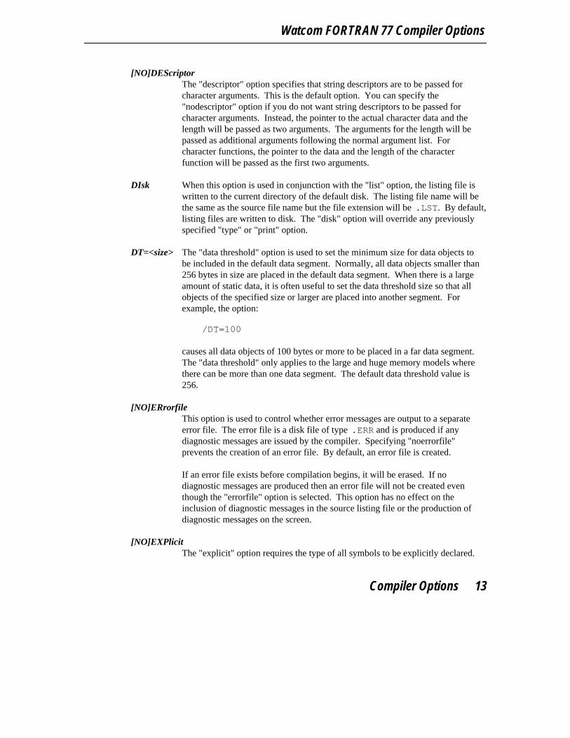
[NO]DEScriptorThe "descriptor" option specifies that string descriptors are to be passed forcharacter arguments. This is the default option. You can specify the"nodescriptor" option if you do not want string descriptors to be passed forcharacter arguments. Instead, the pointer to the actual character data and thelength will be passed as two arguments. The arguments for the length will bepassed as additional arguments following the normal argument list. Forcharacter functions, the pointer to the data and the length of the characterfunction will be passed as the first two arguments.
DIsk When this option is used in conjunction with the "list" option, the listing file iswritten to the current directory of the default disk. The listing file name will bethe same as the source file name but the file extension will be .LST. By default,listing files are written to disk. The "disk" option will override any previouslyspecified "type" or "print" option.
DT=<size> The "data threshold" option is used to set the minimum size for data objects tobe included in the default data segment. Normally, all data objects smaller than256 bytes in size are placed in the default data segment. When there is a largeamount of static data, it is often useful to set the data threshold size so that allobjects of the specified size or larger are placed into another segment. Forexample, the option:
/DT=100
causes all data objects of 100 bytes or more to be placed in a far data segment.The "data threshold" only applies to the large and huge memory models wherethere can be more than one data segment. The default data threshold value is256.
[NO]ERrorfileThis option is used to control whether error messages are output to a separateerror file. The error file is a disk file of type .ERR and is produced if anydiagnostic messages are issued by the compiler. Specifying "noerrorfile"prevents the creation of an error file. By default, an error file is created.
If an error file exists before compilation begins, it will be erased. If nodiagnostic messages are produced then an error file will not be created eventhough the "errorfile" option is selected. This option has no effect on theinclusion of diagnostic messages in the source listing file or the production ofdiagnostic messages on the screen.
[NO]EXPlicitThe "explicit" option requires the type of all symbols to be explicitly declared.
Compiler Options 13

Watcom FORTRAN 77 User’s Guide
An error message will be issued by the compiler if a symbol that does not appearin a type declaration statement is encountered. Specifying this option isequivalent to using the IMPLICIT NONE statement. By default, symbols donot have to be explicitly typed.
[NO]EXtensionsThis option is used to control the printing of extension messages. This optionmay be specified on the command line or it may be placed anywhere in thesource input stream. In a source file, the option appears as a comment line andtakes the following form.
*$[NO]EXtensions
The "extensions" option enables the printing of extension messages, while"noextensions" disables the printing of these messages. By default, extensionmessages are not printed.
[NO]EZ (32-bit only) Watcom F77 will generate an object file in Phar Lap EasyOMF-386 (object module format) instead of the default Microsoft OMF. Thedefault option is "noez".
FO=<obj_default>By default, the object file name is constructed from the source file name. Usingthe "fo" option, the default object file drive, path, file name and extension can bespecified.
Example:C>wfc386 report /fo=d:\programs\obj\
A trailing "\" must be specified for directory names. If, for example, the optionwas specified as "/fo=d:\programs\obj" then the object file would be calledD:\PROGRAMS\OBJ.OBJ.
A default extension must be preceded by a period (".").
Example:C>wfc386 report /fo=d:\programs\obj\.dbo
[NO]FORmatThe "format" option suppresses the run-time checking that ensures that the typeof an input/output list item matches the format edit descriptor in a formatspecification. This allows an input/output list item of type INTEGER to beformatted using an F, E or D edit descriptor. It also allows an input/output listitem of a floating-point type to be formatted using an I edit descriptor.
14 Compiler Options
Watcom FORTRAN 77 Compiler Options
Normally, this generates an error. The "format" option is particularly useful forapplications that use integer arrays to store integer and floating-point data. Thedefault option is "noformat".
FPC All floating-point arithmetic is done with calls to a floating-point emulationlibrary. This option should be used when speed of floating-point emulation isfavoured over code size.
FPI (16-bit only) Watcom F77 will generate in-line 80x87 numeric data processorinstructions into the object code for floating-point operations. Depending onwhich library the code is linked against, these instructions will be left as is orthey will be replaced by special interrupt instructions. In the latter case,floating-point will be emulated if an 80x87 is not present. This is the defaultfloating-point option if none is specified.
(32-bit only) Watcom F77 will generate in-line 80x87 numeric data processorinstructions into the object code for floating-point operations. When anymodule containing floating-point operations is compiled with the "fpi" option,coprocessor emulation software will be included in the application when it islinked. Thus, an 80x87 coprocessor need not be present at run-time. This is thedefault floating-point option if none is specified.
FPI87 (16-bit only) Watcom F77 will generate in-line 80x87 numeric data processorinstructions into the object code for floating-point operations. An 80x87coprocessor must be present at run-time. If the "2" option is used in conjunctionwith this option, Watcom F77 will generate 287/387 compatible instructions;otherwise Watcom F77 will generate 8087 compatible instructions.
(32-bit only) Watcom F77 will generate in-line 80x87 numeric data processorinstructions into the object code for floating-point operations. When the "fpi87"option is used exclusively, coprocessor emulation software is not included in theapplication when it is linked. A 80x87 coprocessor must be present at run-time.
16-bit Notes:
1. When any module in an application is compiled with a particular"floating-point" option, then all modules must be compiled with thesame option.
2. Different math libraries are provided for applications which havebeen compiled with a particular floating-point option. See the chapterentitled "The Watcom FORTRAN 77 Libraries" on page 37.
Compiler Options 15
Watcom FORTRAN 77 User’s Guide
32-bit Notes:
1. When any module in an application is compiled with the "fpc" option,then all modules must be compiled with the "fpc" option.
2. When any module in an application is compiled with the "fpi" or"fpi87" option, then all modules must be compiled with one of thesetwo options.
3. If you wish to have floating-point emulation software included in theapplication, you should select the "fpi" option. A 387 coprocessorneed not be present at run-time.
4. Different math libraries are provided for applications which havebeen compiled with a particular floating-point option. See the chapterentitled "The Watcom FORTRAN 77 Libraries" on page 37.
FP2 Watcom F77 will generate in-line 80x87 numeric data processor instructionsinto the object code for floating-point operations. For Watcom compilersgenerating 16-bit, this is the default. For 32-bit applications, use this option ifyou wish to support those few 386 systems that are equipped with an 80287numeric data processor ("fp3" is the default for Watcom compilers generating32-bit code). However, for 32-bit applications, the use of this option will reduceexecution performance.
FP3 Watcom F77 will generate in-line 387-compatible numeric data processorinstructions into the object code for floating-point operations. For 16-bitapplications, the use of this option will limit the range of systems on which theapplication will run but there are execution performance improvements.
FP5 Watcom F77 will generate in-line 387-compatible numeric data processorinstructions into the object code for floating-point operations. The sequence offloating-point instructions will be optimized for greatest possible performanceon the Intel Pentium processor. For 16-bit applications, the use of this optionwill limit the range of systems on which the application will run but there areexecution performance improvements.
FP6 Watcom F77 will generate in-line 387-compatible numeric data processorinstructions into the object code for floating-point operations. The sequence offloating-point instructions will be optimized for greatest possible performanceon the Intel Pentium Pro processor. For 16-bit applications, the use of thisoption will limit the range of systems on which the application will run but thereare execution performance improvements.
16 Compiler Options
Watcom FORTRAN 77 Compiler Options
[NO]FPD A subtle problem was detected in the FDIV instruction of Intel’s originalPentium CPU. In certain rare cases, the result of a floating-point divide couldhave less precision than it should. Contact Intel directly for more information onthe issue.
As a result, the run-time system startup code has been modified to test for afaulty Pentium. If the FDIV instruction is found to be flawed, the low order bitof the run-time system variable chipbug will be set.
If the FDIV instruction does not show the problem, the low order bit will beclear. If the Pentium FDIV flaw is a concern for your application, there are twoapproaches that you could take:
1. You may test the chipbug variable in your code in allfloating-point and memory models and take appropriate action (suchas display a warning message or discontinue the application).
2. Alternately, you can use the "fpd" option when compiling your code.This option directs the compiler to generate additional code wheneveran FDIV instruction is generated which tests the low order bit ofchipbug and, if on, calls the software workaround code in the
math libraries. If the bit is off, an in-line FDIV instruction will beperformed as before.
If you know that your application will never run on a defective Pentium CPU, oryour analysis shows that the FDIV problem will not affect your results, you neednot use the "fpd" option.
FPR Use this option if you want to generate floating-point instructions that will becompatible with version 9.0 or earlier of the compilers. For more informationon floating-point conventions see the sections entitled "Using the 80x87 to PassArguments" on page 179 and "Using the 80x87 to Pass Arguments" on page245.
[NO]FSfloatsThe "fsfloats" option enables the use of the FS segment register in the generatedcode. This is the default for all but the flat memory model. In the flat memorymodel, the default is "nofsfloats" (the FS segment register is not used in thegenerated code).
[NO]GSfloatsThe "gsfloats" option enables the use of the GS segment register in the generatedcode. This is the default. If you would like to prevent the use of the GSsegment register in the the generated code, specify the "nogsfloats" option.
Compiler Options 17

Watcom FORTRAN 77 User’s Guide
HC The type of debugging information that is to be included in the object file is"Codeview". The default type of debugging information is "Dwarf" (HD). Ifyou wish to use the Microsoft Codeview debugger, then choose the "HC" option.When linking the application, you must also choose the appropriate WatcomLinker DEBUG directive. See the Watcom Linker User’s Guide for moreinformation.
HD The type of debugging information that is to be included in the object file is"Dwarf". This is the default type of debugging information. If you wish to usethe Microsoft Codeview debugger, then choose the "HC" option. When linkingthe application, you must also choose the appropriate Watcom Linker DEBUGdirective. See the Watcom Linker User’s Guide for more information.
HW The type of debugging information that is to be included in the object file is"Watcom". The default type of debugging information is "Dwarf" (HD). If youwish to use the Microsoft Codeview debugger, then choose the "HC" option.When linking the application, you must also choose the appropriate WatcomLinker DEBUG directive. See the Watcom Linker User’s Guide for moreinformation.
[NO]INCListThis option is used to control the listing of the contents of INCLUDE files to thelisting file. The "inclist" option enables the listing of INCLUDE files, while"noinclist" disables the listing of these files. The default option is "noinclist".
INCPath=[d:]path[d:]path... This option is used to specify directories that are to be searched forinclude files. Each path is separated from the previous by a semicolon (";").These directories are searched in the order listed before those in theFINCLUDE environment variable.
[NO]IPromoteThe "ipromote" option causes the compiler to promote the INTEGER*1 andINTEGER*2 arguments of some INTEGER*4 intrinsics without issuing an errordiagnostic. This allows code such as the following to be compiled without error:
18 Compiler Options

Watcom FORTRAN 77 Compiler Options
Example:INTEGER I*1, J*2I = 1J = 2PRINT *, IDIM( I, J )END
This works for the following intrinsic functions: ABS(), IABS(), DIM(),IDIM(), SIGN(), ISIGN(), MAX(), AMAX0(), MAX0(), MIN(), AMIN0(), andMIN0(). When the "ipromote" option is specified, all integer arguments that arepassed to these functions are promoted to INTEGER*4.
Japanese This option is part of the national language support provided by Watcom F77. Itinstructs the compiler that the source code contains characters from the Japanesecharacter set. This includes double-byte characters. This option enables the useof Japanese variable names. The compiler’s run-time system will ensure thatcharacter strings are not split in the middle of a double-byte character whenoutput spans record boundaries (as can happen in list-directed output).
KORean This option is part of the national language support provided by Watcom F77. Itinstructs the compiler that the source code contains characters from the Koreancharacter set. This includes double-byte characters. This option enables the useof Korean variable names. The compiler’s run-time system will ensure thatcharacter strings are not split in the middle of a double-byte character whenoutput spans record boundaries (as can happen in list-directed output).
[NO]LFwithffThis option is used to control whether a line-feed character (LF=CHAR(10)) isto be emitted before a form-feed character (FF=CHAR(12)) is emitted. Thisoption applies to carriage control handling. Normally, the run-time system willemit only a form-feed character to cause a page eject when the ASA controlcharacter "1" is found in the first column of a record. The "lfwithff" option willcause the run-time system to emit a line-feed character and then a form-feedcharacter.
The "lfwithff" option will have little effect on printers, but it will change theappearance of output to the screen by eliminating overwritten text whenform-feed characters are not handled by the output device. The default option is"nolfwithff".
[NO]LIBinfoThis option is used to control the inclusion of default library information in theobject file. The "libinfo" option enables the inclusion of default library
Compiler Options 19
Watcom FORTRAN 77 User’s Guide
information, while "nolibinfo" disables the inclusion of this information. Thedefault option is "libinfo".
[NO]LISt This option may be specified on the command line or it may be placed anywherein the source input stream. On the command line, this option is used to controlthe creation of a listing file. The "list" option causes a listing file to be createdwhile "nolist" requests that no listing file be created. The default option is"nolist".
In a source file, the option appears as a comment line and takes the followingform.
*$[NO]LISt
Specifying *$LIST causes the source lines that follow this option to be listed inthe source listing file while *$NOLIST disables the listing of the source linesthat follow. This option cannot appear on the same source line with otheroptions.
[NO]MAngleThis option is used to alter COMMON block segment and class names.
Example:REAL R, SCOMMON /BLK/ R, SEND
For a named COMMON block called "BLK", the default convention is to namethe segment "BLK" and the class "BLK".
BLK SEGMENT PARA COMMON USE32 ’BLK’
When you use the "mangle" option, the segment is named "_COMMON_BLK"and the class is named "_COMMON_BLK_DATA".
COMMON BLK SEGMENT PARA COMMON USE32 ’ COMMON BLK DATA’
MC (32-bit only) The "compact" memory model (small code, big data) is selected.The various models supported by Watcom F77 are described in the chaptersentitled "16-bit Memory Models" on page 127 and "32-bit Memory Models" onpage 187.
MF (32-bit only) The "flat" memory model (code and data up to 4 gigabytes) isselected. The various models supported by Watcom F77 are described in the
20 Compiler Options
Watcom FORTRAN 77 Compiler Options
chapters entitled "16-bit Memory Models" on page 127 and "32-bit MemoryModels" on page 187. This is the default memory model option.
MH (16-bit only) The "huge" memory model (big code, huge data) is selected. Thevarious models supported by Watcom F77 are described in the chapters entitled"16-bit Memory Models" on page 127 and "32-bit Memory Models" on page187.
ML The "large" memory model (big code, big data) is selected. The various modelssupported by Watcom F77 are described in the chapters entitled "16-bit MemoryModels" on page 127 and "32-bit Memory Models" on page 187. This is thedefault 16-bit memory model option.
MM The "medium" memory model (big code, small data) is selected. The variousmodels supported by Watcom F77 are described in the chapters entitled "16-bitMemory Models" on page 127 and "32-bit Memory Models" on page 187.
MS (32-bit only) The "small" memory model (small code, small data) is selected.The various models supported by Watcom F77 are described in the chaptersentitled "16-bit Memory Models" on page 127 and "32-bit Memory Models" onpage 187.
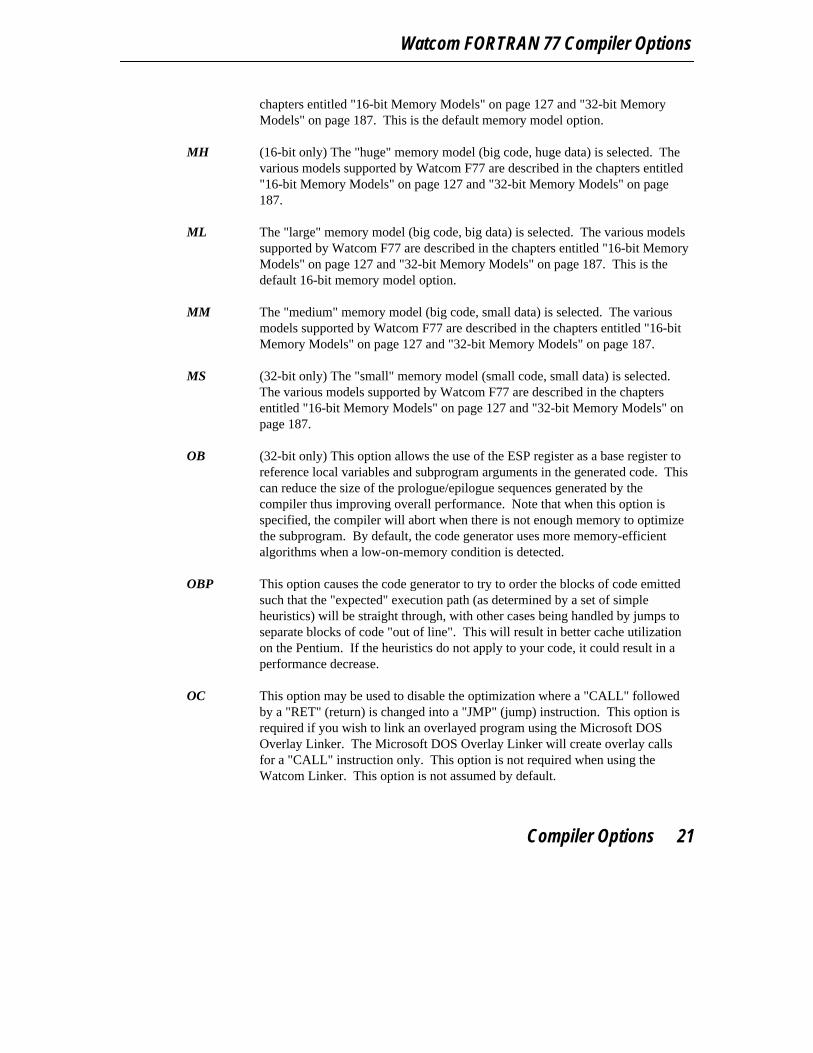
OB (32-bit only) This option allows the use of the ESP register as a base register toreference local variables and subprogram arguments in the generated code. Thiscan reduce the size of the prologue/epilogue sequences generated by thecompiler thus improving overall performance. Note that when this option isspecified, the compiler will abort when there is not enough memory to optimizethe subprogram. By default, the code generator uses more memory-efficientalgorithms when a low-on-memory condition is detected.
OBP This option causes the code generator to try to order the blocks of code emittedsuch that the "expected" execution path (as determined by a set of simpleheuristics) will be straight through, with other cases being handled by jumps toseparate blocks of code "out of line". This will result in better cache utilizationon the Pentium. If the heuristics do not apply to your code, it could result in aperformance decrease.
OC This option may be used to disable the optimization where a "CALL" followedby a "RET" (return) is changed into a "JMP" (jump) instruction. This option isrequired if you wish to link an overlayed program using the Microsoft DOSOverlay Linker. The Microsoft DOS Overlay Linker will create overlay callsfor a "CALL" instruction only. This option is not required when using theWatcom Linker. This option is not assumed by default.
Compiler Options 21

Watcom FORTRAN 77 User’s Guide
OD Non-optimized code sequences are generated. The resulting code will be mucheasier to debug when using Watcom Debugger. By default, Watcom F77 willselect "od" if "d2" is specified.
ODO Optimized DO-loop iteration code is generated. Caution should be exercisedwith the use of this option since the case of an iterating value overflowing isassumed to never occur. The following example should not be compiled withthis option since the terminal value of IX wraps from a positive integer to anegative integer.
Example:INTEGER*2 IXDO IX=32766,32767
.
.
.ENDDO
The values of IX are 32766, 32767, -32768, -32767, ... since IX isINTEGER*2 (a 16-bit signed value) and it never exceeds the terminal value.
OF This option selects the generation of traceable stack frames for those functionsthat contain calls or require stack frame setup. To use Watcom’s "DynamicOverlay Manager" (DOS only), you must compile all modules using the "of"option. For near functions, the following function prologue sequence isgenerated.
16-bit:
push BPmov BP,SP
32-bit:
push EBPmov EBP,ESP
For far functions, the following function prologue sequence is generated.
16-bit:
inc BPpush BPmov BP,SP
22 Compiler Options
Watcom FORTRAN 77 Compiler Options
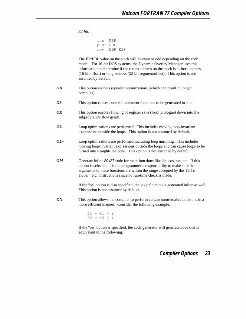
32-bit:
inc EBPpush EBPmov EBP,ESP
The BP/EBP value on the stack will be even or odd depending on the codemodel. For 16-bit DOS systems, the Dynamic Overlay Manager uses thisinformation to determine if the return address on the stack is a short address(16-bit offset) or long address (32-bit segment:offset). This option is notassumed by default.
OH This option enables repeated optimizations (which can result in longercompiles).
OI This option causes code for statement functions to be generated in-line.
OK This option enables flowing of register save (from prologue) down into thesubprogram’s flow graph.
OL Loop optimizations are performed. This includes moving loop-invariantexpressions outside the loops. This option is not assumed by default.
OL+ Loop optimizations are performed including loop unrolling. This includesmoving loop-invariant expressions outside the loops and can cause loops to beturned into straight-line code. This option is not assumed by default.
OM Generate inline 80x87 code for math functions like sin, cos, tan, etc. If thisoption is selected, it is the programmer’s responsibility to make sure thatarguments to these functions are within the range accepted by the fsin,fcos, etc. instructions since no run-time check is made.
If the "ot" option is also specified, the exp function is generated inline as well.This option is not assumed by default.
ON This option allows the compiler to perform certain numerical calculations in amore efficient manner. Consider the following example.
Z1 = X1 / YZ2 = X2 / Y
If the "on" option is specified, the code generator will generate code that isequivalent to the following.
Compiler Options 23

Watcom FORTRAN 77 User’s Guide
T = 1 / YZ1 = X1 * TZ2 = X2 * T
Since floating-point multiplication is more efficient that division, the codegenerator decided to first compute the reciprocal of Y and then multiply X1 andX2 by the reciprocal of Y.
Note that this optimization may produce less slightly different results sincesome, for certain values, precision is lost when computing the reciprocal. Byusing this option, you are indicating that you are willing to accept the loss inprecision for the gain in performance.
OP By default, floating-point variables may be cached in 80x87 floating-pointregisters across statements when compiling with the "fpi" or "fpi87" options.Floating-point register temporaries use 64 bits of precision in the mantissawhereas single and double-precision variables use fewer bits of precision in themantissa. The use of this option will force the result to be stored in memoryafter each FORTRAN statement is executed. This will produce less accurate butmore predictable floating-point results. The code produced will also be lessefficient when the "op" option is used.
Example:XMAX = X + Y / ZYMAX = XMAX + Q
When the "op" option is used in conjunction with the "fpi" or "fpi87" option, thecompiler’s code generator will update XMAX before proceeding with the secondstatement. In the second statement, the compiler will reload XMAX frommemory rather than using the result of the previous statement. The effect of the"op" option on the resulting code can be seen by the increased code size statisticas well as through the use of the Watcom Disassembler. This option is notassumed by default.
OR This option enables reordering of instructions (instruction scheduling) to achievebetter performance on pipelined architectures such as the 486. Selecting thisoption will make it slightly more difficult to debug because the assemblylanguage instructions generated for a source statement may be intermixed withinstructions generated for surrounding statements. This option is not assumedby default.
24 Compiler Options
Watcom FORTRAN 77 Compiler Options
OS Space is favoured over time when generating code (smaller code but possiblyslower execution). By default, Watcom F77 selects a balance between "space"and "time".
OT Time is favoured over space when generating code (faster execution but possiblylarger code). By default, Watcom F77 selects a balance between "space" and"time".
OX Specifying the "ox" option is equivalent to specifying the "ob" (32-bit only),"obp", "odo", "oi", "ok", "ol", "om", "or", and "ot" options.
PRint This option is used to direct the listing file to the printer (device name "PRN")instead of the disk. The "print" option will override any previously specified"type" or "disk" option. The default is to create a listing file on the disk.
[NO]Quiet The "quiet" option suppresses the banner and summary information produced bythe compiler. Only diagnostic messages will be displayed. The default option is"noquiet".
[NO]ReferenceWhen the "reference" option is specified, warning messages will be issued for allunreferenced symbols. In a source file, the option appears as a comment lineand takes the following form.
*$[NO]Reference
This option is most useful when used in an include file that is included byseveral subprograms. Consider an include file that defines many parameterconstants and only a few are referenced by any one subprogram. If the first lineof the include file is
*$noreference
and the last line is *$reference
warning messages for all unused parameter constants in the include file wouldbe suppressed. The default option is "reference".
[NO]RESourceThe "resource" option specifies that the run-time error messages are contained asresource information in the executable file. All messages will be extracted from
Compiler Options 25
Watcom FORTRAN 77 User’s Guide
the resource area of the executable file when they are required; no messages willbe linked with the application. The default option is "noresource".
[NO]SAve The "save" option is used to instruct Watcom F77 to "save" all local variables ofsubprograms. All local variables are treated as if they had appeared inFORTRAN 77 SAVE statements. By default, local variables are not savedunless named in a SAVE statement (i.e., "nosave" is the default option).
[NO]SC (32-bit only) If the "sc" option is used, Watcom F77 will pass all arguments onthe stack. The resulting code will be larger than that which is generated for theregister method of passing arguments. The default option is "nosc".
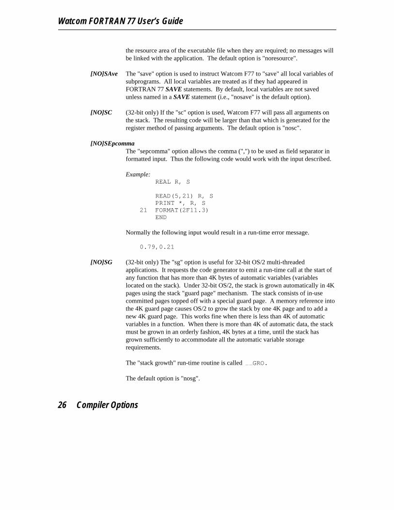
[NO]SEpcommaThe "sepcomma" option allows the comma (",") to be used as field separator informatted input. Thus the following code would work with the input described.
Example:REAL R, S
READ(5,21) R, SPRINT *, R, S
21 FORMAT(2F11.3)END
Normally the following input would result in a run-time error message. 0.79,0.21
[NO]SG (32-bit only) The "sg" option is useful for 32-bit OS/2 multi-threadedapplications. It requests the code generator to emit a run-time call at the start ofany function that has more than 4K bytes of automatic variables (variableslocated on the stack). Under 32-bit OS/2, the stack is grown automatically in 4Kpages using the stack "guard page" mechanism. The stack consists of in-usecommitted pages topped off with a special guard page. A memory reference intothe 4K guard page causes OS/2 to grow the stack by one 4K page and to add anew 4K guard page. This works fine when there is less than 4K of automaticvariables in a function. When there is more than 4K of automatic data, the stackmust be grown in an orderly fashion, 4K bytes at a time, until the stack hasgrown sufficiently to accommodate all the automatic variable storagerequirements.
The "stack growth" run-time routine is called GRO.
The default option is "nosg".
26 Compiler Options
Watcom FORTRAN 77 Compiler Options
[NO]SHort The "short" option is used to instruct Watcom F77 to set the default INTEGERsize to 2 bytes and the default LOGICAL size to 1 bytes. As required by theFORTRAN 77 language standard, the default INTEGER size is 4 bytes and thedefault LOGICAL size is 4 bytes. The default option is "noshort".
[NO]SR The "sr" option instructs Watcom F77 to generate subprogram prologue andepilogue sequences that save and restore any segment registers that are modifiedby the subprogram. Caution should be exercised when using this option. If thevalue of the segment register being restored matches the value of a segment thatwas freed within the subprogram, a general protection fault will occur inprotected-mode environments. The default, "nosr", does not save and restoresegment registers.
[NO]SSfloats(16-bit only) The "ssfloats" option specifies that the segment register SS doesnot necessarily point to the default data segment. The "ssfloats" option must bespecified when compiling a module that is part of an OS/2 multi-threadedapplication or dynamic link library. By default, it is assumed that the SSsegment register contains the segment address of the default data segment (i.e.,"nossfloats").
[NO]STack If "stack" is specified, Watcom F77 will emit code at the beginning of everysubprogram that will check for the "stack overflow" condition. By default, stackoverflow checking is omitted from the generated code ("nostack").
[NO]SYntax If "syntax" is specified, Watcom F77 will check the source code only and omitthe generation of object code. Syntax checking, type checking, and so on areperformed as usual. By default, code is generated if there are no source codeerrors (i.e., "nosyntax" is the default).
[NO]TErminalThe "noterminal" option may be used to suppress the display of diagnosticmessages to the screen. By default, diagnostic messages are displayed.
[NO]TRace The "trace" option causes the generation of code that allows a traceback to beissued when an error occurs during the execution of your program. The defaultoption is "notrace".
TYpe This option is used to direct the listing file to the terminal (device name "CON")instead of the disk. The "type" option will override any previously specified"print" or "disk" option. The default is to create a listing file on the disk.
[NO]WArningsThis option is used to control the printing of warning messages. By default,
Compiler Options 27
Watcom FORTRAN 77 User’s Guide
warning messages are printed. This option may be specified on the commandline or it may be placed anywhere in the source input stream. In a source file,the option appears as a comment line and takes the following form.
*$[NO]WArnings
The "warnings" option enables the printing of warning messages, while"nowarnings" disables the printing of these messages.
[NO]WILd The "wild" option suppresses the compile-time checking that normally causes anerror to be issued when an attempt is made to transfer control into a blockstructure from outside the block structure and vice versa. For example, thisoption will allow a transfer of control into an IF-block from outside the IF-block(which is normally prohibited). The default option is "nowild".
Extreme caution should be exercised when using this option. For example,transfer of control into a DO-loop from outside the DO-loop can causeunpredictable results. This programming style is not encouraged by this option.The option has been made available so that existing programs that do not adhereto the branching restrictions imposed by the FORTRAN 77 standard (i.e.mainframe applications that are being ported to the PC environment), can becompiled by Watcom FORTRAN 77.
[NO]WIndows(16-bit only) The "windows" option causes the compiler to generate theprologue/epilogue code sequences necessary for use in Microsoft Windowsapplications. The default option is "nowindows".
[NO]XFloat The "xfloat" option specifies that all REAL variables are treated as if they hadbeen declared as "DOUBLE PRECISION". This effectively increases theprecision of REAL variables. Note that the "xfloat" option has implications onthe alignment of variables in common blocks. The default option is "noxfloat".
[NO]Xline The "xline" option informs the Watcom F77 compiler to extend the last columnof the statement portion of a line to column 132. The default is 72.
28 Compiler Options
3 The Watcom FORTRAN 77 Compiler
This chapter describes the following topics:
• Command line syntax (see "Watcom FORTRAN 77 Command Line Format")
• Environment variables used by the compilers (see "WFC/WFC386 EnvironmentVariables" on page 30)
• Examples of command line syntax (see "Watcom FORTRAN 77 Command LineExamples" on page 31)
• Interpreting diagnostic messages (see "Compiler Diagnostics" on page 32)
• Include file handling (see "Watcom FORTRAN 77 INCLUDE File Processing" onpage 35)
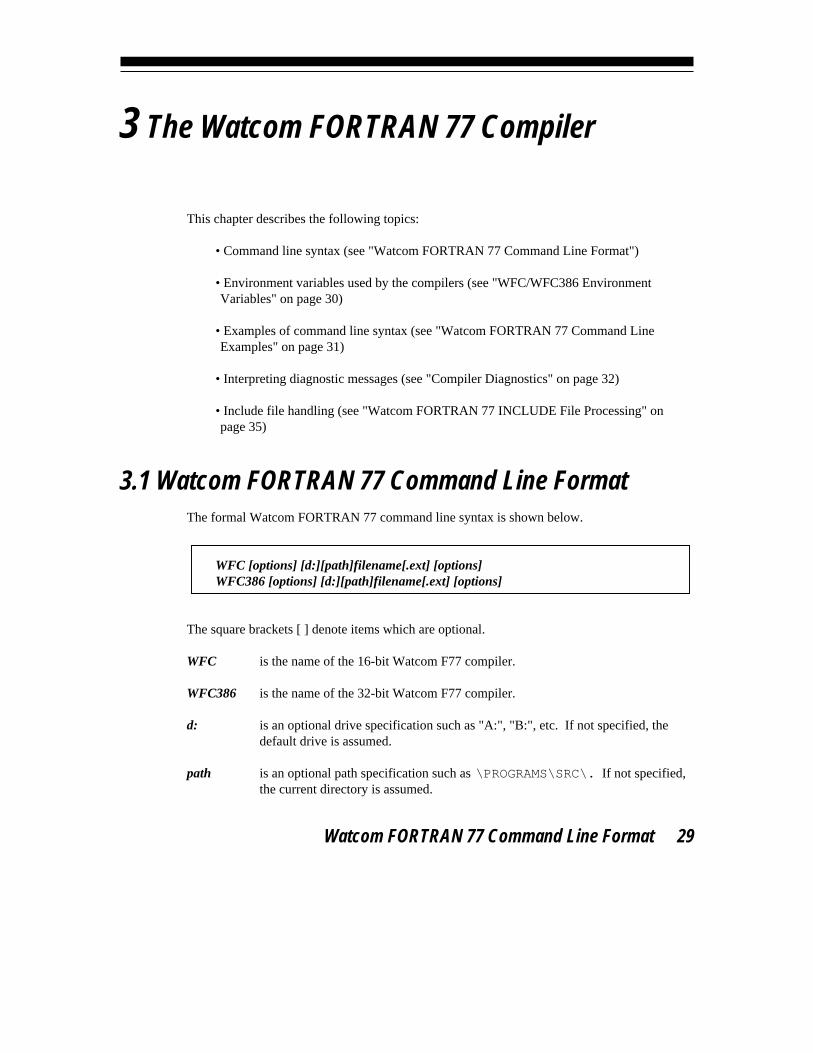
3.1 Watcom FORTRAN 77 Command Line FormatThe formal Watcom FORTRAN 77 command line syntax is shown below.
WFC [options] [d:][path]filename[.ext] [options]WFC386 [options] [d:][path]filename[.ext] [options]
The square brackets [ ] denote items which are optional.
WFC is the name of the 16-bit Watcom F77 compiler.
WFC386 is the name of the 32-bit Watcom F77 compiler.
d: is an optional drive specification such as "A:", "B:", etc. If not specified, thedefault drive is assumed.
path is an optional path specification such as \PROGRAMS\SRC\. If not specified,the current directory is assumed.
Watcom FORTRAN 77 Command Line Format 29

Watcom FORTRAN 77 User’s Guide
filename is the file name of the file to be compiled.
ext is the file extension of the file to be compiled. If omitted, a file extension of"FOR" is assumed. If the period "." is specified but not the extension, the file isassumed to have no file extension.
options is a list of valid Watcom F77 options, each preceded by a slash ("/") or a dash("−"). Certain options can include a "no" prefix to disable an option. Optionsmay be specified in any order, with the rightmost option taking precedence overany conflicting options specified to its left.
3.2 WFC/WFC386 Environment VariablesThe WFC environment variable can be used to specify commonly used WFC options. TheWFC386 environment variable can be used to specify commonly used WFC386 options.These options are processed before options specified on the command line.
Example:C>set wfc=/d1 /otC>set wfc386=/d1 /ot
The above example defines the default options to be "d1" (include line number debugginginformation in the object file), and "ot" (favour time optimizations over size optimizations).
Whenever you wish to specify an option that requires the use of an "=" character, you can usethe "#" character in its place. This is required by the syntax of the "SET" command.
Once a particular environment variable has been defined, those options listed become thedefault each time the associated compiler is used. The compiler command line can be used tooverride any options specified in the environment string.
These environment variables are not examined by the Watcom Compile and Link utilities.Since the Watcom Compile and Link utilities pass the relevant options found in theirassociated environment variables to the compiler command line, their environment variableoptions take precedence over the options specified in the environment variables associatedwith the compilers.
30 WFC/WFC386 Environment Variables

The Watcom FORTRAN 77 Compiler
Hint: If you are running DOS and you use the same compiler options all the time, youmay find it handy to define the environment variable in your DOS system initializationfile, AUTOEXEC.BAT.
If you are running Windows NT, use the "System" icon in the Control Panel to defineenvironment variables.
If you are running OS/2 and you use the same compiler options all the time, you may findit handy to define the environment variable in your OS/2 system initialization file,CONFIG.SYS.
3.3 Watcom FORTRAN 77 Command Line ExamplesThe following are some examples of using Watcom FORTRAN 77 to compile FORTRAN 77source programs.
Example 1:C>wfc386 report /d1 /stack
The 32-bit Watcom F77 compiler processes REPORT.FOR producing an object file whichcontains source line number information. Stack overflow checking code is included in theobject code.
Example 2:C>wfc kwikdraw /2 /fpi87
The 16-bit Watcom F77 compiler processes KWIKDRAW.FOR producing object code for anIntel 286 system equipped with an Intel 287 numeric data processor (or any upwardcompatible 386/387, 486 or Intel Pentium system). While the choice of these options narrowsthe number of microcomputer systems where this code will execute, the resulting code will behighly optimized for this type of system.
Example 3:C>wfc ..\source\modabs /d2
The 16-bit Watcom F77 compiler processes ..\SOURCE\MODABS.FOR (a file in adirectory which is adjacent to the current one). The object file is placed in the currentdirectory. Included with the object code and data is information on local symbols and datatypes. The code generated is straight-forward, unoptimized code which can be readilydebugged with Watcom Debugger.
Watcom FORTRAN 77 Command Line Examples 31

Watcom FORTRAN 77 User’s Guide
Example 4:C>wfc386 /mf calc
The 32-bit Watcom F77 compiler compiles CALC.FOR for the "flat" memory model. 32-bitmemory models are described in the chapter entitled "32-bit Memory Models" on page 187.32-bit argument passing conventions are described in the chapter entitled "32-bit AssemblyLanguage Considerations" on page 193.
Example 5:C>wfc386 kwikdraw /fpi87
The 32-bit Watcom F77 compiler processes KWIKDRAW.FOR producing object code for anIntel 386 system equipped with an Intel 80x87 numeric data processor.
Example 6:C>set wfc=/short /d2 /fo#*.dbjC>wfc ..\source\modabs
The options /short, /d2 and /fo=*.dbj are established as defaults using the WFCenvironment variable. The 16-bit compiler processes ..\SOURCE\MODABS.FOR (a file ina directory which is adjacent to the current one). The object file is placed in the currentdirectory and it will have a default file extension of "DBJ". All INTEGER and LOGICALvariables will have a default type of INTEGER*2 and LOGICAL*1 unless explicitly typed asINTEGER*4 or LOGICAL*4. Source line number and local symbol information are includedwith the object file.
3.4 Compiler DiagnosticsIf the Watcom F77 compiler prints diagnostic messages to the screen, it will also place a copyof these messages in a file in your current directory (unless the "noerrorfile" option isspecified). The file will have the same file name as the source file and an extension of "err".The compiler issues three types of diagnostic messages, namely extensions, warnings anderrors. An extension message indicates that you have used a feature which is supported byWatcom F77 but that is not part of the FORTRAN 77 language standard. A warning messageindicates that the compiler has found a questionable problem in the source code (e.g., anunreachable statement, an unreferenced variable or statement number, etc.). A warningmessage does not prevent the production of an object file. An error message indicates that aproblem is severe enough that it must be corrected before the compiler will produce an objectfile. The error file is a handy reference when you wish to correct the errors in the source file.
Just to illustrate the diagnostic features of Watcom F77, we will compile the followingprogram called "DEMO1".
32 Compiler Diagnostics
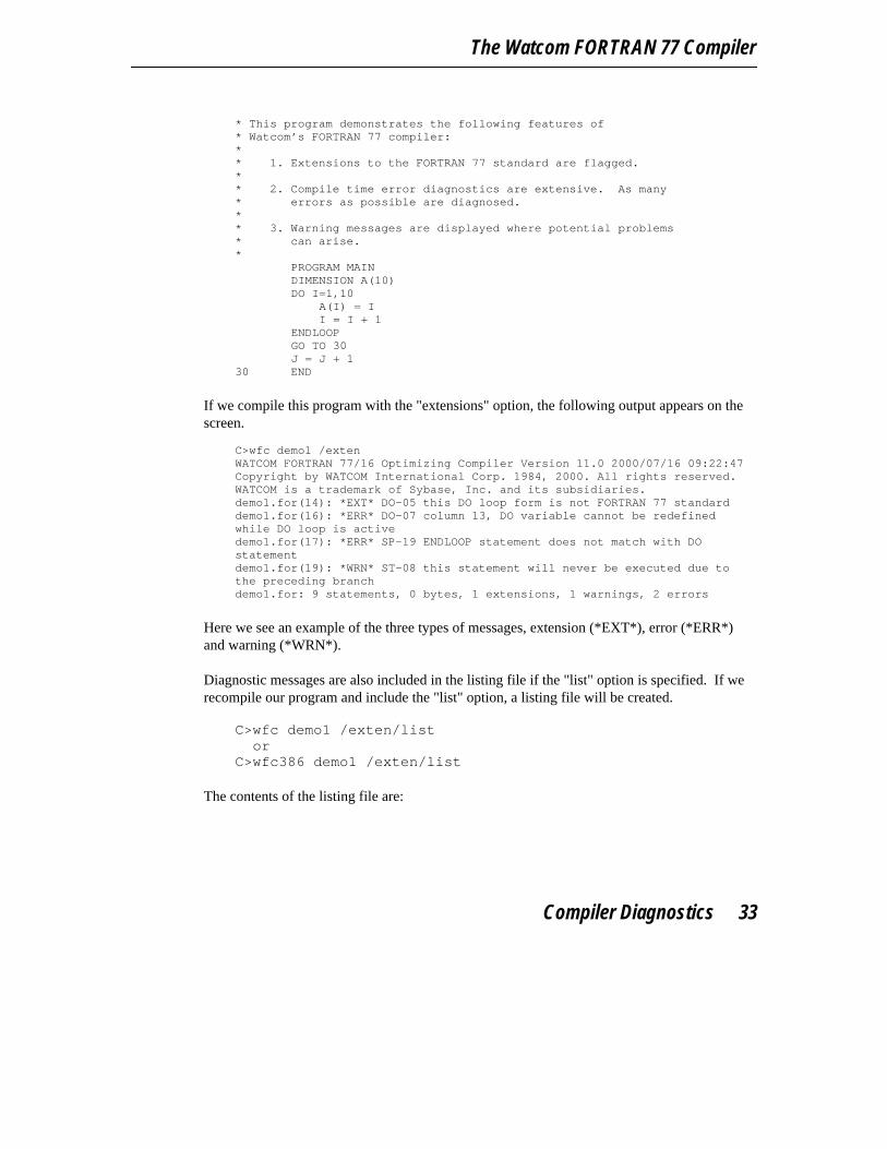
The Watcom FORTRAN 77 Compiler
* This program demonstrates the following features of* Watcom’s FORTRAN 77 compiler:** 1. Extensions to the FORTRAN 77 standard are flagged.** 2. Compile time error diagnostics are extensive. As many* errors as possible are diagnosed.** 3. Warning messages are displayed where potential problems* can arise.*
PROGRAM MAINDIMENSION A(10)DO I=1,10
A(I) = II = I + 1
ENDLOOPGO TO 30J = J + 1
30 END
If we compile this program with the "extensions" option, the following output appears on thescreen.
C>wfc demo1 /extenWATCOM FORTRAN 77/16 Optimizing Compiler Version 11.0 2000/07/16 09:22:47Copyright by WATCOM International Corp. 1984, 2000. All rights reserved.WATCOM is a trademark of Sybase, Inc. and its subsidiaries.demo1.for(14): *EXT* DO-05 this DO loop form is not FORTRAN 77 standarddemo1.for(16): *ERR* DO-07 column 13, DO variable cannot be redefinedwhile DO loop is activedemo1.for(17): *ERR* SP-19 ENDLOOP statement does not match with DOstatementdemo1.for(19): *WRN* ST-08 this statement will never be executed due tothe preceding branchdemo1.for: 9 statements, 0 bytes, 1 extensions, 1 warnings, 2 errors
Here we see an example of the three types of messages, extension (*EXT*), error (*ERR*)and warning (*WRN*).
Diagnostic messages are also included in the listing file if the "list" option is specified. If werecompile our program and include the "list" option, a listing file will be created.
C>wfc demo1 /exten/list
orC>wfc386 demo1 /exten/list
The contents of the listing file are:
Compiler Diagnostics 33

Watcom FORTRAN 77 User’s Guide
WATCOM FORTRAN 77/16 Optimizing Compiler Version 11.0 2000/07/16 09:22:47Copyright by WATCOM International Corp. 1984, 2000. All rights reserved.WATCOM is a trademark of Sybase, Inc. and its subsidiaries.
Options: list,disk,errorfile,extensions,reference,warnings,fpi,oc,of,om,os,ot,ox,ml,0,terminal,dependency,fsfloats,gsfloats,libinfo,dt=256,align
1 * This program demonstrates the following features of2 * Watcom’s FORTRAN 77 compiler:3 *4 * 1. Extensions to the FORTRAN 77 standard are flagged.5 *6 * 2. Compile time error diagnostics are extensive. As many7 * errors as possible are diagnosed.8 *9 * 3. Warning messages are displayed where potential problems
10 * can arise.11 *12 PROGRAM MAIN13 DIMENSION A(10)14 DO I=1,10
*EXT* DO-05 this DO loop form is not FORTRAN 77 standard15 A(I) = I16 I = I + 1
$*ERR* DO-07 DO variable cannot be redefined while DO loop is active
17 ENDLOOP*ERR* SP-19 ENDLOOP statement does not match with DO statement
18 GO TO 3019 J = J + 1
*WRN* ST-08 this statement will never be executed due to the precedingbranch
20 30 END
Code size (in bytes): 0 Number of errors: 2Compile time (in seconds): 0 Number of warnings: 1Number of statements compiled: 9 Number of extensions: 1
As part of the diagnostic capability of Watcom F77, a "$" is often used to indicate theparticular place in the source line where an error has been detected.
The complete list of Watcom F77 diagnostic messages is presented in the appendix entitled"Watcom F77 Diagnostic Messages" on page 265.
34 Compiler Diagnostics

The Watcom FORTRAN 77 Compiler
3.5 Watcom FORTRAN 77 INCLUDE File ProcessingFor information on include file processing, see the section entitled "The INCLUDE CompilerDirective" on page 44 in the chapter entitled "Watcom FORTRAN 77 Compiler Directives"
Watcom FORTRAN 77 INCLUDE File Processing 35

Watcom FORTRAN 77 User’s Guide
36 Watcom FORTRAN 77 INCLUDE File Processing

4 The Watcom FORTRAN 77 Libraries
The Watcom FORTRAN 77 library routines (intrinsic functions) are described in the WatcomFORTRAN 77 Language Reference manual. Additional run-time routines are described in thechapter entitled "The Watcom F77 Subprogram Library" on page 79. Since WatcomFORTRAN 77 supports two major architectures, the 286 architecture (which includes the8088) and the 386 architecture (which includes the 486 and Pentium processors), libraries aregrouped under two major directories.
For the 286 architecture, the processor dependent libraries are placed under the\WATCOM\LIB286 directory.
For the 386 architecture, the processor dependent libraries are placed under the\WATCOM\LIB386 directory.
Since Watcom FORTRAN 77 also supports several operating systems, including DOS,Windows 3.x, Windows 95, Windows NT, OS/2 and NetWare, system-dependent libraries aregrouped under different directories underneath the processor-dependent directories.
System 16-bit applications 32-bit applications--------- --------------------- ---------------------DOS \WATCOM\LIB286\DOS \WATCOM\LIB386\DOS
OS/2 \WATCOM\LIB286\OS2 \WATCOM\LIB386\OS2
Windows 3.x \WATCOM\LIB286\WIN \WATCOM\LIB386\WIN
Windows NT \WATCOM\LIB386\NTWindows 95
NetWare \WATCOM\LIB386\NETWARE
The Watcom FORTRAN 77 Libraries 37
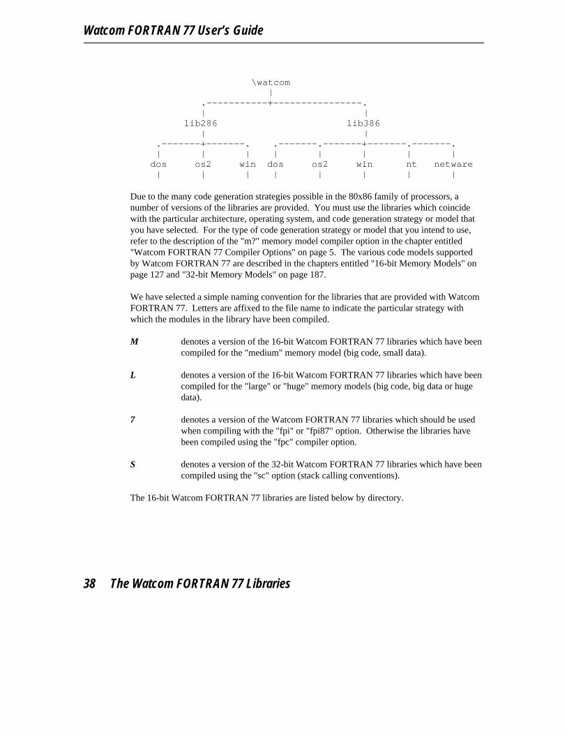
Watcom FORTRAN 77 User’s Guide
\watcom
|.-----------+----------------.| |
lib286 lib386| |
.-------+-------. .-------.-------+-------.-------.| | | | | | | |
dos os2 win dos os2 win nt netware| | | | | | | |
Due to the many code generation strategies possible in the 80x86 family of processors, anumber of versions of the libraries are provided. You must use the libraries which coincidewith the particular architecture, operating system, and code generation strategy or model thatyou have selected. For the type of code generation strategy or model that you intend to use,refer to the description of the "m?" memory model compiler option in the chapter entitled"Watcom FORTRAN 77 Compiler Options" on page 5. The various code models supportedby Watcom FORTRAN 77 are described in the chapters entitled "16-bit Memory Models" onpage 127 and "32-bit Memory Models" on page 187.
We have selected a simple naming convention for the libraries that are provided with WatcomFORTRAN 77. Letters are affixed to the file name to indicate the particular strategy withwhich the modules in the library have been compiled.
M denotes a version of the 16-bit Watcom FORTRAN 77 libraries which have beencompiled for the "medium" memory model (big code, small data).
L denotes a version of the 16-bit Watcom FORTRAN 77 libraries which have beencompiled for the "large" or "huge" memory models (big code, big data or hugedata).
7 denotes a version of the Watcom FORTRAN 77 libraries which should be usedwhen compiling with the "fpi" or "fpi87" option. Otherwise the libraries havebeen compiled using the "fpc" compiler option.
S denotes a version of the 32-bit Watcom FORTRAN 77 libraries which have beencompiled using the "sc" option (stack calling conventions).
The 16-bit Watcom FORTRAN 77 libraries are listed below by directory.
38 The Watcom FORTRAN 77 Libraries
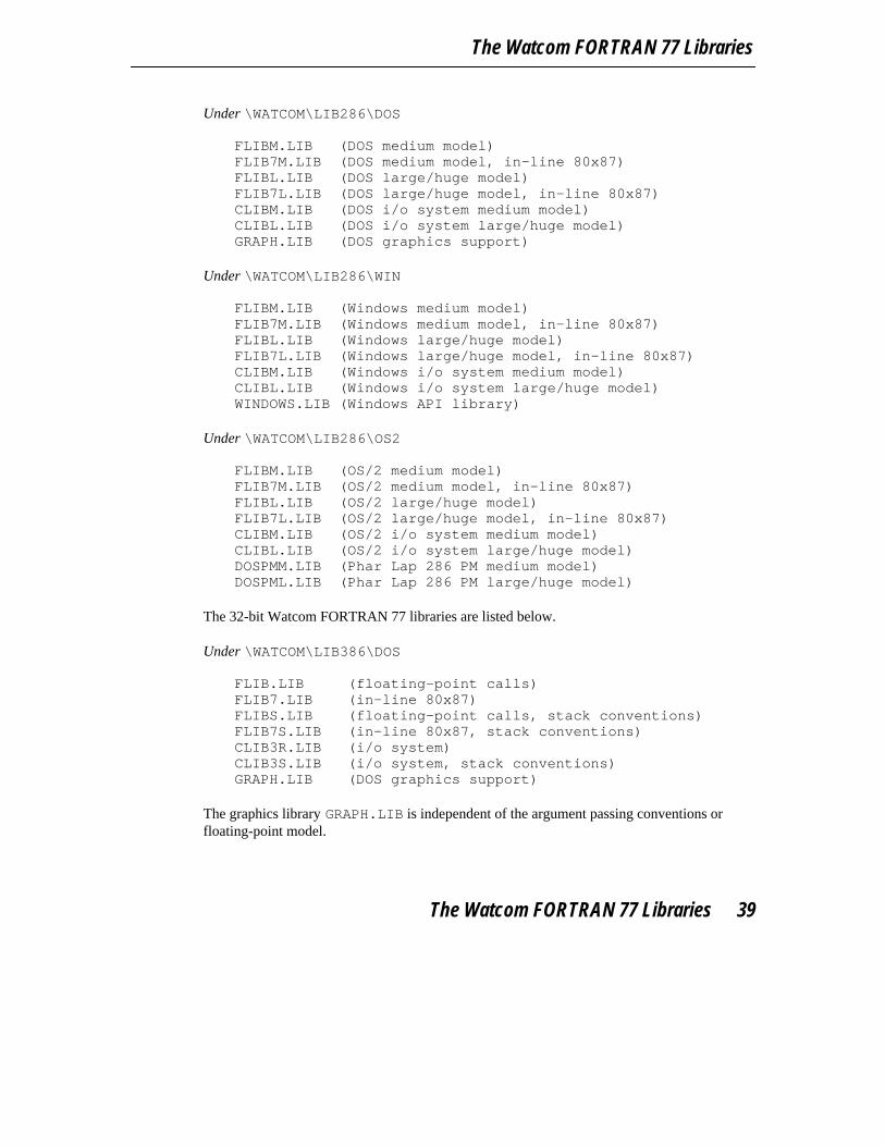
The Watcom FORTRAN 77 Libraries
Under \WATCOM\LIB286\DOS FLIBM.LIB (DOS medium model)FLIB7M.LIB (DOS medium model, in-line 80x87)FLIBL.LIB (DOS large/huge model)FLIB7L.LIB (DOS large/huge model, in-line 80x87)CLIBM.LIB (DOS i/o system medium model)CLIBL.LIB (DOS i/o system large/huge model)GRAPH.LIB (DOS graphics support)
Under \WATCOM\LIB286\WIN FLIBM.LIB (Windows medium model)FLIB7M.LIB (Windows medium model, in-line 80x87)FLIBL.LIB (Windows large/huge model)FLIB7L.LIB (Windows large/huge model, in-line 80x87)CLIBM.LIB (Windows i/o system medium model)CLIBL.LIB (Windows i/o system large/huge model)WINDOWS.LIB (Windows API library)
Under \WATCOM\LIB286\OS2 FLIBM.LIB (OS/2 medium model)FLIB7M.LIB (OS/2 medium model, in-line 80x87)FLIBL.LIB (OS/2 large/huge model)FLIB7L.LIB (OS/2 large/huge model, in-line 80x87)CLIBM.LIB (OS/2 i/o system medium model)CLIBL.LIB (OS/2 i/o system large/huge model)DOSPMM.LIB (Phar Lap 286 PM medium model)DOSPML.LIB (Phar Lap 286 PM large/huge model)
The 32-bit Watcom FORTRAN 77 libraries are listed below.
Under \WATCOM\LIB386\DOS FLIB.LIB (floating-point calls)FLIB7.LIB (in-line 80x87)FLIBS.LIB (floating-point calls, stack conventions)FLIB7S.LIB (in-line 80x87, stack conventions)CLIB3R.LIB (i/o system)CLIB3S.LIB (i/o system, stack conventions)GRAPH.LIB (DOS graphics support)
The graphics library GRAPH.LIB is independent of the argument passing conventions orfloating-point model.
The Watcom FORTRAN 77 Libraries 39
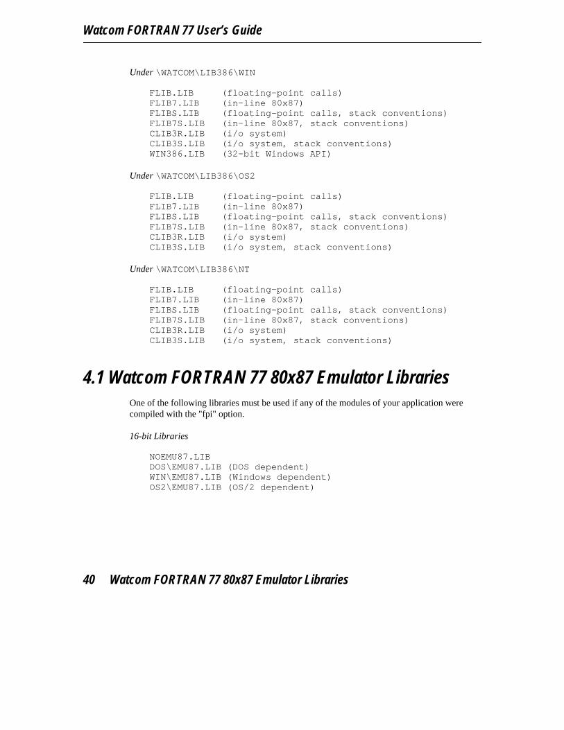
Watcom FORTRAN 77 User’s Guide
Under \WATCOM\LIB386\WIN FLIB.LIB (floating-point calls)FLIB7.LIB (in-line 80x87)FLIBS.LIB (floating-point calls, stack conventions)FLIB7S.LIB (in-line 80x87, stack conventions)CLIB3R.LIB (i/o system)CLIB3S.LIB (i/o system, stack conventions)WIN386.LIB (32-bit Windows API)
Under \WATCOM\LIB386\OS2 FLIB.LIB (floating-point calls)FLIB7.LIB (in-line 80x87)FLIBS.LIB (floating-point calls, stack conventions)FLIB7S.LIB (in-line 80x87, stack conventions)CLIB3R.LIB (i/o system)CLIB3S.LIB (i/o system, stack conventions)
Under \WATCOM\LIB386\NT FLIB.LIB (floating-point calls)FLIB7.LIB (in-line 80x87)FLIBS.LIB (floating-point calls, stack conventions)FLIB7S.LIB (in-line 80x87, stack conventions)CLIB3R.LIB (i/o system)CLIB3S.LIB (i/o system, stack conventions)
4.1 Watcom FORTRAN 77 80x87 Emulator LibrariesOne of the following libraries must be used if any of the modules of your application werecompiled with the "fpi" option.
16-bit Libraries NOEMU87.LIBDOS\EMU87.LIB (DOS dependent)WIN\EMU87.LIB (Windows dependent)OS2\EMU87.LIB (OS/2 dependent)
40 Watcom FORTRAN 77 80x87 Emulator Libraries

The Watcom FORTRAN 77 Libraries
32-bit Libraries NOEMU387.LIBDOS\EMU387.LIB (DOS dependent)WIN\EMU387.LIB (Windows dependent)OS2\EMU387.LIB (OS/2 dependent)NT\EMU387.LIB (Windows NT dependent)
The "fpi" option causes an 80x87 numeric data processor emulator to be linked into yourapplication. This emulator will decode and emulate 80x87 instructions when an 80x87 is notpresent in the system or if the environment variable NO87 has been set (this variable isdescribed below).
If you have compiled your application using the "fpi" option, you can also link with the 16-bit"noemu87.lib" or 32-bit "noemu387.lib" library, depending on which compiler you are using.However, your application will only run on a machine equipped with a 80x87 numeric dataprocessor since the actual emulator is not linked into your application.
When the "fpi87" option is used exclusively, the emulator is not included. In this case, theapplication must be run on personal computer systems equipped with the numeric dataprocessor.
4.2 The "NO87" Environment VariableIf you have a math coprocessor in your system but you wish to test a version of yourapplication that will use floating-point emulation ("fpi" option) or simulation ("fpc" option),you can define the NO87 environment variable. The 16-bit application must be compiledusing the "fpc" (floating-point calls) option and linked with the appropriate FLIB?.LIBlibrary or the "fpi" option (default) and linked with the appropriate FLIB7?.LIB andEMU87.LIB libraries. The 32-bit application must be compiled using the "fpc"(floating-point calls) option and linked with the appropriate FLIB?.LIB library or the "fpi"option (default) and linked with the appropriate FLIB7?.LIB and EMU387.LIB libraries.Using the "SET" command, define the environment variable as follows:
C>SET NO87=1
Now, when you run your application, the 80x87 will be ignored. To undefine theenvironment variable, enter the command:
C>SET NO87=
The "NO87" Environment Variable 41

Watcom FORTRAN 77 User’s Guide
42 The "NO87" Environment Variable

5 Watcom FORTRAN 77 Compiler Directives
5.1 IntroductionA number of compiler directives are available that allow, for example, conditionalcompilation of source code and the inclusion of source code from other files. A compilerdirective is specified by placing a comment character (’c’, ’C’, or ’*’) in column one followedby a dollar sign (’$’) immediately followed by the compiler directive. The following lists allof the compiler directives available with Watcom F77.
1. EJECT2. INCLUDE3. PRAGMA4. DEFINE5. UNDEFINE6. IFDEF7. IFNDEF8. ENDIF9. ELSE10. ELIFDEF11. ELIFNDEF
These compiler directives will be described in the following sections.
In addition to the above compiler directives, it is also possible to specify certain compileroptions in the same way. The following lists these options.
1. [NO]EXTENSIONS2. [NO]LIST3. [NO]REFERENCE4. [NO]WARNINGS
For more information on these options, see the the chapter entitled "Watcom FORTRAN 77Compiler Options" on page 5.
Introduction 43

Watcom FORTRAN 77 User’s Guide
5.2 The EJECT Compiler DirectiveThis compiler directive causes a form-feed to be generated in the listing file. The listing file isa carriage-control file that is created by the compiler when the "list" compiler option isspecified. In the following example, a form-feed character will be generated immediatelybefore the source for subroutine sub2 and immediately before the source for subroutinesub3.
Example:subroutine sub1! source codeend
*$ejectsubroutine sub2! source codeend
*$ejectsubroutine sub3! source codeend
5.3 The INCLUDE Compiler DirectiveThe INCLUDE compiler directive or INCLUDE statement may be used to imbed source codeinto the file being compiled. Either form may be used.
Example:*$INCLUDE DOS.FI
INCLUDE ’DOS.FI’
When the INCLUDE statement is used the name of the file must be placed inside singlequotes (apostrophes). The file name may include drive, path, and file extension. The defaultfile extension is .FOR.
It is not necessary to include the drive and path specifiers in the file specification when the fileresides on a different drive or in a different directory. Watcom F77 provides a mechanism forlooking up include files which may be located in various directories and disks of the computersystem. When the drive and path are omitted from a file specification, Watcom F77 searchesdirectories for include files in the following order.
1. First, the current directory is searched.
44 The INCLUDE Compiler Directive

Watcom FORTRAN 77 Compiler Directives
2. Secondly, each directory listed with the "INCPath" option is searched (in the orderthat they were specified).
3. Thirdly, each directory listed in the FINCLUDE environment variable is searched(in the order that they were specified).
The compiler will search the directories listed with the "INCPath" option or in theFINCLUDE environment variable in a manner analogous to that which used by the operatingsystem when searching for programs by using the PATH environment variable.
The "INCPath" option takes the following form. /INCPath=[d:]path;[d:]path...
The "SET" command is used to define an FINCLUDE environment variable that contains alist of directories. A command of the form
SET FINCLUDE=[d:]path;[d:]path...
is issued before running Watcom F77 the first time. The brackets indicate that the drive D: isoptional and the ellipsis indicates that any number of paths may be specified.
We illustrate the use of the INCLUDE statement in the following example.
subroutine ClearScreen()implicit noneinclude ’dos.fi’integer VIDEO CALL, SCROLL UPparameter (VIDEO CALL=16, SCROLL UP=6)DS = ES = FS = GS = 0 ! for safety on 386 DOS extenderAH = SCROLL UP ! scroll upAL = 0 ! blank entire windowCX = 0 ! set row,column of upper leftDX = 24*256 + 80 ! set row,column of lower rightBH = 7 ! attribute "white on black"call fintr( VIDEO CALL, regs )end
The third line of this subroutine contains an INCLUDE statement for the file DOS.FI. If theabove source code is stored in the file CLRSCR.FOR in the current directory then we canissue the following commands to compile the application.
C>set finclude=c:\watcom\src\fortran\dosC>wfc clsscr
In the above example, the "SET" command is used to define the FINCLUDE environmentvariable. It specifies that the \WATCOM\SRC\FORTRAN\DOS directory is to be searched forinclude files that cannot be located in the current directory and that have no drive or pathspecified. The advantage of the FINCLUDE environment variable is that drives and paths
The INCLUDE Compiler Directive 45

Watcom FORTRAN 77 User’s Guide
can be omitted from the INCLUDE file specifications in the source code. This allows thesource code to be independent of the disk/directory structure of your computer system.
5.4 The PRAGMA Compiler DirectiveThis compiler directive is described in the chapters entitled "16-bit Pragmas" on page 147 and"32-bit Pragmas" on page 211.
5.5 The DEFINE Compiler DirectiveThe DEFINE compiler directive sets the definition status of a macro to defined. If a macrodoes not appear in a DEFINE directive, its definition status is undefined.
Example:*$define debug
In the above example, the macro debug is defined.
The DEFINE compiler option can also be used to define a macro.
Example:C>wfc /define=debug testC>wfc386 /define=debug test
5.6 The UNDEFINE Compiler DirectiveThe UNDEFINE compiler directive sets the definition status of a macro to undefined.
Example:*$undefine debug
In the above example, the definition status of the macro debug is set to undefined.
46 The UNDEFINE Compiler Directive
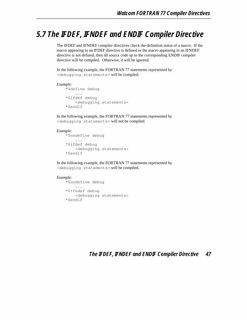
Watcom FORTRAN 77 Compiler Directives
5.7 The IFDEF, IFNDEF and ENDIF Compiler DirectiveThe IFDEF and IFNDEF compiler directives check the definition status of a macro. If themacro appearing in an IFDEF directive is defined or the macro appearing in an IFNDEFdirective is not defined, then all source code up to the corresponding ENDIF compilerdirective will be compiled. Otherwise, it will be ignored.
In the following example, the FORTRAN 77 statements represented by<debugging statements> will be compiled.
Example:*$define debug
...*$ifdef debug
<debugging statements>*$endif
In the following example, the FORTRAN 77 statements represented by<debugging statements> will not be compiled.
Example:*$undefine debug
...*$ifdef debug
<debugging statements>*$endif
In the following example, the FORTRAN 77 statements represented by<debugging statements> will be compiled.
Example:*$undefine debug
...*$ifndef debug
<debugging statements>*$endif
The IFDEF, IFNDEF and ENDIF Compiler Directive 47

Watcom FORTRAN 77 User’s Guide
5.8 The ELSE Compiler DirectiveThe ELSE compiler directive must be preceded by an IFDEF, IFNDEF, ELSEIFDEF orELSEIFNDEF compiler directive. If the condition of the preceding compiler directive wassatisfied, then all source code between the ELSE compiler directive and the correspondingENDIF compiler directive will be ignored. If the condition of the preceding compilerdirective was not satisfied, then all source code between the ELSE compiler directive and thecorresponding ENDIF compiler directive will be compiled.
In the following example, the FORTRAN 77 statements represented by<debugging level 2 statements> will be compiled.
Example:*$undefine debug level 1
...*$ifdef debug level 1
<debugging level 1 statements>*$else
<debugging level 2 statements>*$endif
5.9 The ELSEIFDEF and ELSEIFNDEF CompilerDirective
The ELSEIFDEF and ELSEIFNDEF compiler directives must be preceded by an IFDEF,IFNDEF, ELSEIFDEF or ELSEIFNDEF compiler directive. If the condition of the precedingcompiler directive was satisfied, then all source code between the ELSEIFDEF orELSEIFNDEF compiler directive and the corresponding ENDIF compiler directive will beignored. If the condition of the preceding compiler directive was not satisfied, then thedefinition status of the macro specified in the ELSEIFDEF or ELSEIFNDEF compilerdirective is checked. If the macro appearing in the ELSEIFDEF compiler directive is defined,or the macro appearing in the ELSEIFNDEF compiler directive is not defined, then all sourceup to the next ELSEIFDEF, ELSEIFNDEF, ELSE or ENDIF compiler directive will becompiled.
In the following example, the FORTRAN 77 statements represented by<debugging level 2 statements> will be compiled.
48 The ELSEIFDEF and ELSEIFNDEF Compiler Directive
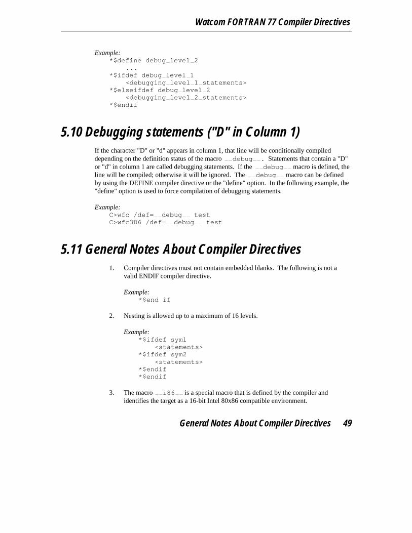
Watcom FORTRAN 77 Compiler Directives
Example:*$define debug level 2
...*$ifdef debug level 1
<debugging level 1 statements>*$elseifdef debug level 2
<debugging level 2 statements>*$endif
5.10 Debugging statements ("D" in Column 1)If the character "D" or "d" appears in column 1, that line will be conditionally compileddepending on the definition status of the macro debug . Statements that contain a "D"or "d" in column 1 are called debugging statements. If the debug macro is defined, theline will be compiled; otherwise it will be ignored. The debug macro can be definedby using the DEFINE compiler directive or the "define" option. In the following example, the"define" option is used to force compilation of debugging statements.
Example:C>wfc /def= debug testC>wfc386 /def= debug test
5.11 General Notes About Compiler Directives1. Compiler directives must not contain embedded blanks. The following is not a
valid ENDIF compiler directive.
Example:*$end if
2. Nesting is allowed up to a maximum of 16 levels.
Example:*$ifdef sym1
<statements>*$ifdef sym2
<statements>*$endif*$endif
3. The macro i86 is a special macro that is defined by the compiler andidentifies the target as a 16-bit Intel 80x86 compatible environment.
General Notes About Compiler Directives 49
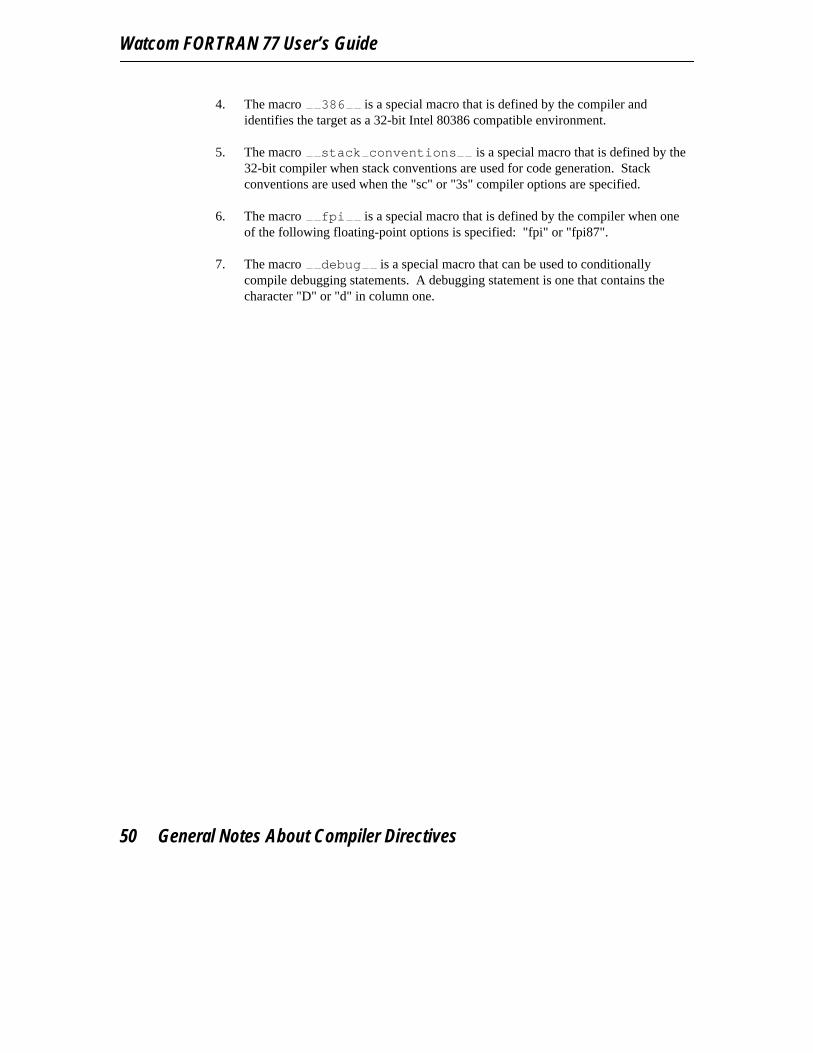
Watcom FORTRAN 77 User’s Guide
4. The macro 386 is a special macro that is defined by the compiler andidentifies the target as a 32-bit Intel 80386 compatible environment.
5. The macro stack conventions is a special macro that is defined by the32-bit compiler when stack conventions are used for code generation. Stackconventions are used when the "sc" or "3s" compiler options are specified.
6. The macro fpi is a special macro that is defined by the compiler when oneof the following floating-point options is specified: "fpi" or "fpi87".
7. The macro debug is a special macro that can be used to conditionallycompile debugging statements. A debugging statement is one that contains thecharacter "D" or "d" in column one.
50 General Notes About Compiler Directives

6 Watcom FORTRAN 77 File Handling
This chapter describes the file handling and naming conventions of Watcom F77. We discussfiles and devices which are used to store, retrieve and display data. For example, a disk can beused to store a file of student marks. This file is accessible by other programs in order toproduce summaries of the data such as marks reports. A device such as a printer can also betreated as if it were a file, although it is only useful for displaying data; an attempt to readinformation from this device is invalid.
In the following sections, we shall describe:
1. the techniques that Watcom F77 adopts for implementing FORMATTED andUNFORMATTED records and SEQUENTIAL and DIRECT access to these records,
2. the handling of "print" files,3. file naming conventions,4. logical file names,5. the preconnection of files to units, and6. special device support.
6.1 Record AccessTwo types of record access are supported by Watcom F77:
Sequential Sequential access means that records in a file are accessed in order, starting withthe first record in the file and proceeding to the last. Sequential access ispermitted to records in both variable-length and fixed-length record files.
Direct Direct access means that records in a file are accessed in random order. Forexample, the fifth record could be accessed, then the second, and then the tenth.Direct access is permitted for fixed-length record files only.
The access method is described using the ACCESS= specifier of the FORTRAN OPENstatement. The default access is "SEQUENTIAL".
Record Access 51
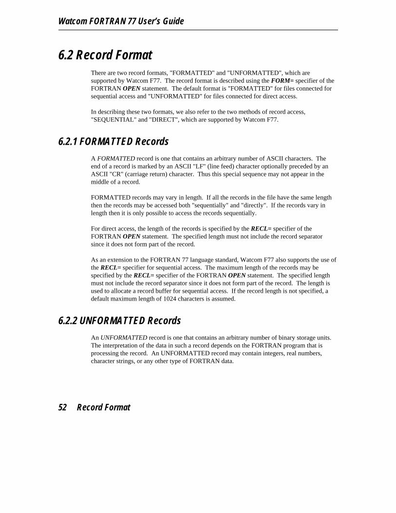
Watcom FORTRAN 77 User’s Guide
6.2 Record FormatThere are two record formats, "FORMATTED" and "UNFORMATTED", which aresupported by Watcom F77. The record format is described using the FORM= specifier of theFORTRAN OPEN statement. The default format is "FORMATTED" for files connected forsequential access and "UNFORMATTED" for files connected for direct access.
In describing these two formats, we also refer to the two methods of record access,"SEQUENTIAL" and "DIRECT", which are supported by Watcom F77.
6.2.1 FORMATTED Records
A FORMATTED record is one that contains an arbitrary number of ASCII characters. Theend of a record is marked by an ASCII "LF" (line feed) character optionally preceded by anASCII "CR" (carriage return) character. Thus this special sequence may not appear in themiddle of a record.
FORMATTED records may vary in length. If all the records in the file have the same lengththen the records may be accessed both "sequentially" and "directly". If the records vary inlength then it is only possible to access the records sequentially.
For direct access, the length of the records is specified by the RECL= specifier of theFORTRAN OPEN statement. The specified length must not include the record separatorsince it does not form part of the record.
As an extension to the FORTRAN 77 language standard, Watcom F77 also supports the use ofthe RECL= specifier for sequential access. The maximum length of the records may bespecified by the RECL= specifier of the FORTRAN OPEN statement. The specified lengthmust not include the record separator since it does not form part of the record. The length isused to allocate a record buffer for sequential access. If the record length is not specified, adefault maximum length of 1024 characters is assumed.
6.2.2 UNFORMATTED Records
An UNFORMATTED record is one that contains an arbitrary number of binary storage units.The interpretation of the data in such a record depends on the FORTRAN program that isprocessing the record. An UNFORMATTED record may contain integers, real numbers,character strings, or any other type of FORTRAN data.
52 Record Format

Watcom FORTRAN 77 File Handling
UNFORMATTED records may also vary in length. If all records in the file have the samelength then the records may be accessed both "sequentially" and "directly". If the recordsvary in length then it is only possible to access the records sequentially.
When a file containing UNFORMATTED records is accessed sequentially, each record mustbegin and end with a descriptor that contains the length of the record. The length of therecord is represented in 32 bits or 4 bytes (INTEGER*4). The UNFORMATTED records of afile which are written using sequential access will be automatically supplied with theappropriate length descriptors. When such a file is read, it is assumed that each record has theappropriate length descriptors.
Depending on the record length, the output produced by a single unformatted sequentialWRITE statement may cause multiple records to be written. As previously mentioned, eachrecord begins and ends with a length descriptor. The length descriptors for the first recordcontain the length of the record. The length descriptors for the remaining records contain thelength of the record with the high bit (bit 31) set to one. In this way, an unformattedsequential file can be viewed as a number of logical records (a logical record corresponding tothe output produced by a WRITE statement) with each logical record composed of a numberof physical records. Files created in this way cannot be accessed directly unless each logicalrecord is composed of a single physical record and each record is the same size.
As an extension to the FORTRAN 77 language standard, Watcom F77 also supports the use ofthe RECL= specifier for sequential access. The maximum length of the records may bespecified by the RECL= specifier of the FORTRAN OPEN statement. The specified lengthmust not include the length descriptors since they do not form part of the record. The lengthis used to allocate a record buffer for sequential access. If the record length is not specified, adefault maximum length of 1024 characters is assumed.
When a file containing UNFORMATTED records is accessed directly, each record must bethe same length. In this case, the length of the records is specified by the RECL= specifier ofthe FORTRAN OPEN statement. If the file was originally created with sequential access thenthe specified length must include any length descriptors which form part of the record. In thedirect access mode, no interpretation is placed on any of the data in an UNFORMATTEDrecord and the programmer must account for any record length descriptors which may formpart of the record.
Any records which are written using direct access must include record length descriptors if thefile is to be accessed sequentially at a later time. As an alternative, you may specifyRECORDTYPE=’VARIABLE’ in the FORTRAN OPEN statement. This specifier is anextension to the FORTRAN 77 language standard and will cause length descriptors to begenerated automatically. In this case, the record length should not include the record lengthdescriptors.
Record Format 53

Watcom FORTRAN 77 User’s Guide
6.2.3 Files with no Record Structure
Certain files, for example a file created by a program written in another language, do not haveany internal record structure that matches any of the record structures supported by WatcomF77. These files are simply streams of data. There are two ways in which these files can beprocessed.
1. You can use unformatted direct access. In this case, the value specified by theRECL= specifier in the OPEN statement determines the amount of data read orwritten by a READ or WRITE statement.
2. Alternatively, you can use unformatted sequential access. In this case, the amountof data read or written to the file is determined by the items in the input/output listof the READ or WRITE statement. When using unformatted sequential access,you must specify RECORDTYPE=’FIXED’ to indicate that no record boundariesare present. Otherwise, the default value of ’VARIABLE’ will be used.
6.3 Attributes of FilesThe file system does not retain any information on the contents of a file. Unlike moresophisticated file systems, it cannot report whether a file consists of fixed-length orvariable-length records, how records are delimited in a file, the maximum length of therecords, etc. Therefore, we have provided a mechanism which will allow you to specifyadditional information about a file. This mechanism should be used when the defaultassumptions about records in a file are not true for the file in question.
The RECORDTYPE= specifier of the FORTRAN OPEN statement can be used to specifyadditional information about the type of records in the file. This specifier is an extension tothe FORTRAN 77 language standard.
The RECL= specifier of the FORTRAN OPEN statement can be used to specify additionalinformation about the length of records in the file. When used with sequential access, thisspecifier is an extension to the FORTRAN 77 language standard.
The CARRIAGECONTROL= specifier of the FORTRAN OPEN statement can be used tospecify additional information about the handling of ASA carriage control characters for anoutput file. This specifier is an extension to the FORTRAN 77 language standard.
The BLOCKSIZE= specifier of the FORTRAN OPEN statement can be used to specify thesize of the internal input/output buffer. A buffer reduces the number of system input/outputcalls during input/output to a particular file and hence improves the overall performance of a
54 Attributes of Files

Watcom FORTRAN 77 File Handling
program. The default buffer size is 4K. This specifier is an extension to the FORTRAN 77language standard.
The following sections describe the attributes of records supported by the Watcom F77run-time system.
6.3.1 Record Type
The RECORDTYPE= specifier of the FORTRAN OPEN statement can be used to specifyadditional information about the type of records in the file. This specifier is an extension tothe FORTRAN 77 language standard. The following types may be specified.
RECORDTYPE=’TEXT’RECORDTYPE=’VARIABLE’RECORDTYPE=’FIXED’
TEXT indicates that the file contains variable-length or fixed-length records of ASCIIcharacters separated by an ASCII "LF" (line feed) character optionally precededwith an ASCII "CR" (carriage return) character. By default, the Watcom F77run-time system assumes that FORMATTED records are of TEXT format inboth the sequential and direct access modes.
By default, the Watcom F77 run-time system uses variable-length record TEXTfiles to implement FORMATTED records in the sequential access mode. Ofcourse, all records may be the same length. The record separator is not includedin calculating the maximum size of records in the file.
By default, the Watcom F77 run-time system uses fixed-length record TEXTfiles to implement FORMATTED records in the direct access mode. Eachrecord must be the same length. The record separator is not included incalculating the size of records in the file.
VARIABLE indicates that the file contains variable-length or fixed-length records in whichspecial descriptors are employed to describe the length of each record. Thelength of each record is contained in a doubleword (INTEGER*4 item) at thebeginning and end of the record. These descriptors determine the bounds of therecords.
By default, the Watcom F77 run-time system uses VARIABLE format files toimplement UNFORMATTED records in the sequential access mode. Thelength descriptors are required to support the FORTRAN BACKSPACEstatement since no other method exists for determining the bounds of avariable-length unformatted record in a file.
Attributes of Files 55

Watcom FORTRAN 77 User’s Guide
FIXED indicates that the file contains no extra information that determines the recordstructure. If the file is a direct access file, the value specified by the RECL=specifier determines the size of each record in the file.
By default, the Watcom F77 run-time system uses FIXED format files toimplement UNFORMATTED records in the direct access mode.
If you specify FIXED with an unformatted sequential file, the size of the recordsis determined by the items in the input/output list.
6.3.2 Record Size
When access is direct, the record length must be specified in the RECL= specifier of theFORTRAN OPEN statement.
OPEN( UNIT=1, FILE=’TEST.DAT’, ACCESS=’DIRECT’, RECL=size, ... )
As an extension to the FORTRAN 77 language standard, the record length may also bespecified when the access is sequential. This should be done whenever access is "sequential"and the maximum record length is greater than the default.
OPEN( UNIT=1, FILE=’TEST.DAT’, ACCESS=’SEQUENTIAL’, RECL=size, ... )
The record length specified by size should not include record separators such as CR and LF,nor should it include record length descriptors when sequentially accessing a file containingunformatted records. However, for all files, records longer than the size specified will betruncated. The default record size is 1024. The maximum record size is 65535 for the 16-bitrun-time system. Since record buffers are allocated in the dynamic storage region, the sizewill be restricted to the amount of dynamic storage available.
6.3.3 Print File Attributes
When the first character of each record written to a file will contain an ASA (AmericanStandards Association) carriage control character, the CARRIAGECONTROL= specifier ofthe FORTRAN OPEN statement should be used. This specifier is an extension to theFORTRAN 77 language standard. The ASA character is used for vertical spacing control.The valid characters and their interpretation are:
56 Attributes of Files
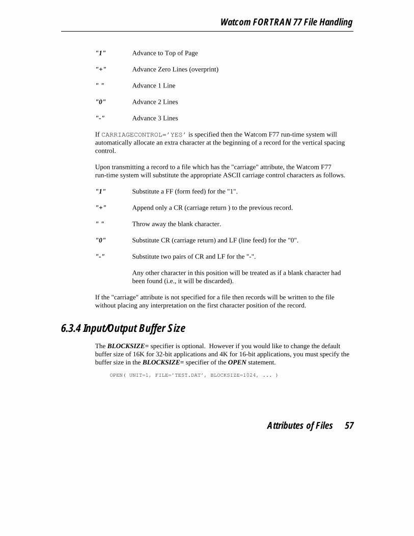
Watcom FORTRAN 77 File Handling
"1" Advance to Top of Page
"+" Advance Zero Lines (overprint)
" " Advance 1 Line
"0" Advance 2 Lines
"-" Advance 3 Lines
If CARRIAGECONTROL=’YES’ is specified then the Watcom F77 run-time system willautomatically allocate an extra character at the beginning of a record for the vertical spacingcontrol.
Upon transmitting a record to a file which has the "carriage" attribute, the Watcom F77run-time system will substitute the appropriate ASCII carriage control characters as follows.
"1" Substitute a FF (form feed) for the "1".
"+" Append only a CR (carriage return ) to the previous record.
" " Throw away the blank character.
"0" Substitute CR (carriage return) and LF (line feed) for the "0".
"-" Substitute two pairs of CR and LF for the "-".
Any other character in this position will be treated as if a blank character hadbeen found (i.e., it will be discarded).
If the "carriage" attribute is not specified for a file then records will be written to the filewithout placing any interpretation on the first character position of the record.
6.3.4 Input/Output Buffer Size
The BLOCKSIZE= specifier is optional. However if you would like to change the defaultbuffer size of 16K for 32-bit applications and 4K for 16-bit applications, you must specify thebuffer size in the BLOCKSIZE= specifier of the OPEN statement.
OPEN( UNIT=1, FILE=’TEST.DAT’, BLOCKSIZE=1024, ... )
Attributes of Files 57
Watcom FORTRAN 77 User’s Guide
6.3.5 File Sharing
On systems that support multi-tasking or networking, it is possible for for a file to be accessedsimultaneously by more that one process. There are two specifiers in the OPEN statementthat can be used to control the way in which files are shared between processes.
The ACTION= specifier indicates the way in which the file is initially accessed. That is, theway in which the first process to open the file accesses the file. The values allowed for theACTION= specifier are the following.
’READ’ the file is opened for read-only access
’WRITE’ the file is opened for write-only access
’READWRITE’ the file is opened for both read and write access
The SHARE= specifier can be used to indicate the manner in which subsequent processes areallowed to access the file while the file is open. The values allowed for the SHARE=specifier are the following.
’COMPAT’ no other process may open the file
’DENYRW’ other processes are denied read and write access
’DENYWR’ other process are denied write access (allowed read-only access)
’DENYRD’ other process are denied read access (allowed write-only access)
’DENYNONE’ other processes are allowed read and write access
Let us consider the following scenario. Suppose you want several processes to read a file andprevent any process that is reading the file from changing its contents. We first must establishthe method of access for the first process that opens the file. In this case, we want read-onlyaccess so the ACTION=’READ’ specifier must be used. Next, we must establish the methodof access for subsequent processes. In our example, we do not want any process to makechanges to the file. Therefore, we use the SHARE=’DENYWR’ specifier. The file would beopened using the following OPEN statement.
OPEN( UNIT=1, FILE=’TEST.DAT’, ACTION=’READ’, SHARE=’DENYWR’, ... )
58 Attributes of Files
Watcom FORTRAN 77 File Handling
6.4 File Names in the FAT File SystemThe FAT file system is supported by DOS and OS/2. OS/2 also supports the HighPerformance File System (HPFS) which will be discussed in a later section. File namingconventions are used to form file designations in a given file system. The file designation fora FAT file system has the following form.
[d:][path]filename[.ext]
[] The square brackets denote items which are optional.
d: is the drive name. If omitted, the default drive is assumed.
Examples of drive names are: A:, B:, C:, and D:.
path is called a "path" specification. The path may be used to refer to files that arestored in sub-directories of the disk. The complete file specification (includingdrive, path and file name) cannot exceed 143 characters.
Some examples of path specifications are: \plot\\bench\tools\\fortran\pgms\
Your operating system manuals can tell you more about directories: how tocreate them, how to store files in them, how to specify a path, etc.
filename is the main part of the file’s name. The filename can contain up to 8 characters.If more than 8 characters are used, only the first 8 are meaningful. For example,"COUNTRIES" and "COUNTRIE" are treated as the same name for a file.
ext is an optional extension consisting of 1 to 3 characters (e.g., DOC). If anextension is specified, it is separated from the filename by a period. Extensionsare normally used to indicate the type of information stored in the file. Forexample, a file extension of FOR is a common convention for FORTRANprograms.
File Names in the FAT File System 59

Watcom FORTRAN 77 User’s Guide
Note: The file specification is case insensitive in that upper and lower case letters can beused interchangeably.
6.4.1 Special DOS Device Names
Certain file names are reserved for devices. These special device names are: CON the console (or terminal)AUX the serial portCOM1 another name for the serial portCOM2 a second serial portPRN the parallel printerLPT1 another name for the printerLPT2 a second parallel printerLPT3 a third parallel printerNUL nonexistent device
When using one of these special device names, no other part of the file designation should bespecified. A common mistake is to attempt to create a disk file such as PRN.DAT and attemptto write records to it. If you do not have a parallel printer attached to your PC, there may be along delay before the output operation times out.
6.4.2 Examples of FAT File Specifications
The following are some examples of valid file specifications.
1. The following file designation refers to a file in the current directory of the defaultdisk.
OPEN( UNIT=1, FILE=’DATA.FIL’, ... )
2. The following file designation refers to a print file in the current directory of driveC:. ASA carriage control characters will be converted to the appropriate ASCIIcontrol codes.
OPEN( UNIT=2, FILE=’C:REPORT.LST’,CARRIAGECONTROL=’YES’, ... )
3. The file specification below indicates that the file is to have fixed format records oflength 80.
60 File Names in the FAT File System
Watcom FORTRAN 77 File Handling
OPEN( UNIT=3, FILE=’FINAL.TST’,RECL=80, RECORDTYPE=’FIXED’, ... )
4. The file specification below indicates that the file is to have variable format recordsof maximum length 145.
OPEN( UNIT=4, FILE=’TERM.RPT’,RECL=145, RECORDTYPE=’VARIABLE’, ... )
5. The file designation below indicates that the file resides in the RECORDS directoryof drive B:.
OPEN( UNIT=5, FILE=’B:\RECORDS\CUSTOMERS.DAT’, ... )
Note that the trailing "S" in the file name will be ignored. Thus the followingdesignation is equivalent.
OPEN( UNIT=5, FILE=’B:\RECORDS\CUSTOMER.DAT’, ... )
6. The file designation below refers to the second serial port.
OPEN( UNIT=6, FILE=’COM2’, ... )
7. The file designation below refers to a second parallel printer.
OPEN( UNIT=7, FILE=’LPT2’, ... )
6.5 File Names in the High Performance File SystemOS/2, in addition to supporting the FAT file system, also supports the High Performance FileSystem (HPFS). The rules for forming file names in the High Performance File System aredifferent from those used to form file names in the FAT file system. In HPFS, file names anddirectory names can be up to 254 characters in length. However, the complete path (includingdrive, directories and file name) cannot exceed 259 characters. The period is a valid file namecharacter and can appear in a file name or directory name as many times as required; HPFSfile names do not require file extensions as in the FAT file system. However, manyapplications still use the period to denote file extensions.
The HPFS preserves case in file names only in directory listings but ignores case in filesearches and other system operations. For example, a directory cannot have more than onefile whose names differ only in case.
File Names in the High Performance File System 61

Watcom FORTRAN 77 User’s Guide
6.5.1 Special OS/2 Device Names
The OS/2 operating system has reserved certain file names for character devices. Thesespecial device names are:
CLOCK$ ClockCOM1 First serial portCOM2 Second serial portCOM3 Third serial portCOM4 Fourth serial portCON Console keyboard and screenKBD$ KeyboardLPT1 First parallel printerLPT2 Second parallel printerLPT3 Third parallel printerMOUSE$ MouseNUL Nonexistent (dummy) devicePOINTER$ Pointer draw device (mouse screen support)PRN The default printer, usually LPT1SCREEN$ Screen
When using one of these special device names, no other part of the file designation should bespecified.
6.5.2 Examples of HPFS File Specifications
The following are some examples of valid file specifications.
1. The following file designation refers to a file in the current directory of the defaultdisk.
OPEN( UNIT=1, FILE=’DATA.FIL’, ... )
2. The following file designation refers to a print file in the current directory of driveC:. ASA carriage control characters will be converted to the appropriate ASCIIcontrol codes.
OPEN( UNIT=2, FILE=’C:REPORT.LST’,CARRIAGECONTROL=’YES’, ... )
3. The file specification below indicates that the file is to have fixed format records oflength 80.
OPEN( UNIT=3, FILE=’FINAL.TST’,RECL=80, RECORDTYPE=’FIXED’, ... )
62 File Names in the High Performance File System

Watcom FORTRAN 77 File Handling
4. The file specification below indicates that the file is to have variable format recordsof maximum length 145.
OPEN( UNIT=4, FILE=’TERM.RPT’,RECL=145, RECORDTYPE=’VARIABLE’, ... )
5. The file designation below indicates that the file resides in the RECORDS directoryof drive B:.
OPEN( UNIT=5, FILE=’B:\RECORDS\CUSTOMERS.DAT’, ... )
Note that the trailing "S" in the file name is not ignored as is the case in a FAT filesystem.
6. The file designation below refers to the second serial port.
OPEN( UNIT=6, FILE=’COM2’, ... )
7. The file designation below refers to a second parallel printer.
OPEN( UNIT=7, FILE=’LPT2’, ... )
6.6 Establishing Connections Between Units and FilesUsing Watcom F77, FORTRAN unit numbers may range from 0 to 999. Input/outputstatements such as READ and WRITE refer to files by a unit number. All input/outputstatements except OPEN, CLOSE, and INQUIRE must refer to a unit that is connected to afile. The Watcom F77 run-time system automatically establishes the connection of a unit to afile if no connection previously existed. Any connection between a unit and a file that isestablished before execution begins is called a preconnection.
The Watcom F77 run-time system defines a preconnection of the unit designated by "*" to thestandard input and output devices (by this we generally mean the keyboard and screen of thepersonal computer but input/output can be redirected from/to a file using the standardinput/output redirectors "<" and ">" on the command line). This preconnection cannot bealtered in any way. Unit "*" is explicitly or implicitly referred to by the following inputstatements:
READ, ...READ *, ...READ format-spec, ...READ(*,...) ...READ(UNIT=*,...) ...
Establishing Connections Between Units and Files 63
Watcom FORTRAN 77 User’s Guide
Unit "*" is explicitly or implicitly referred to by the following output statements: PRINT, ...PRINT *, ...PRINT format-spec, ...WRITE(*,...) ...WRITE(UNIT=*,...) ...
The Watcom F77 run-time system also defines a preconnection of unit 5 to the standard inputdevice (by this we generally mean the keyboard of the personal computer but input can beredirected from a file using the standard input redirector "<" on the command line).
The Watcom F77 run-time system also defines a preconnection of unit 6 to the standardoutput device (by this we generally mean the screen of the personal computer but output canbe redirected to a file using the standard output redirector ">" on the command line).
For all other allowable units, a default preconnection between unit number "nnn" and the fileFORNNN is assumed when no connection between a unit and a file has been established. nnnis a three-digit FORTRAN unit number. Unit 0 is "000", unit 1 is "001", unit 2 is "002", andso on. There is no file extension in this case. In other words, a default file name isconstructed for any unit number for which no other connection has been established.Input/output statements of the following forms refer to these units.
CLOSE(nnn,...) OPEN(nnn,...)CLOSE(UNIT=nnn,...) OPEN(UNIT=nnn,...)BACKSPACE nnn READ(nnn,...)BACKSPACE(nnn) READ(UNIT=nnn,...)BACKSPACE(UNIT=nnn) REWIND nnnENDFILE nnn REWIND(nnn)ENDFILE(nnn) REWIND(UNIT=nnn)ENDFILE(UNIT=nnn) WRITE(nnn,...) ...INQUIRE(nnn,...) WRITE(UNIT=nnn,...) ...INQUIRE(UNIT=nnn,...)
Of course, it is unlikely that one would be satisfied with using such undistinguished file namessuch as FOR000, FOR001, and so on. Therefore, the Watcom F77 run-time system providesadditional ways of establishing a preconnection between a FORTRAN UNIT and a file.
The Watcom F77 run-time system supports the use of the "SET" command to establish aconnection between a unit and a file. The "SET" command is used to create, modify andremove "Environment Variables". The "SET" command must be issued before running aprogram. The format for a preconnection using the "SET" command is:
SET unit=file spec
64 Establishing Connections Between Units and Files

Watcom FORTRAN 77 File Handling
where description:
unit is a FORTRAN unit number in the range 0 to 999.
If this form of the "SET" command is used then FORTRAN unit number unit ispreconnected to the specified file. FORTRAN input/output statements whichrefer to the unit number will access the records in the specified file.
file_spec is the file specification of the preconnected file.
Here are some sample "SET" commands.
Example:C>set 1=input.datC>set 2=output.datC>set 3=d:\database\customer.fil
The above example establishes the following preconnections:
1. Between unit 1 and the file INPUT.DAT which resides (or will reside) in thecurrent directory.
2. Between unit 2 and the file OUTPUT.DAT which resides (or will reside) in thecurrent directory.
3. Between unit 3 and the file D:\DATABASE\CUSTOMER.FIL which resides (orwill reside) in another disk and directory.
Any FORTRAN input/output statements which refer to units 1, 2 or 3 will act upon one ofthese 3 data files.
Notes:
1. The "SET" command must be issued before running the program.
2. No spaces should be placed before or after the "=" in the "SET" command. Thefollowing two examples are quite distinct from each other:
Establishing Connections Between Units and Files 65
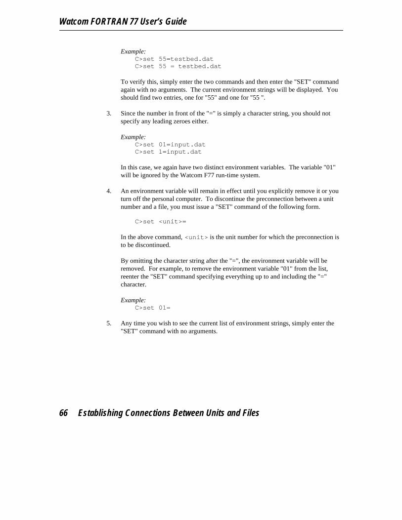
Watcom FORTRAN 77 User’s Guide
Example:C>set 55=testbed.datC>set 55 = testbed.dat
To verify this, simply enter the two commands and then enter the "SET" commandagain with no arguments. The current environment strings will be displayed. Youshould find two entries, one for "55" and one for "55 ".
3. Since the number in front of the "=" is simply a character string, you should notspecify any leading zeroes either.
Example:C>set 01=input.datC>set 1=input.dat
In this case, we again have two distinct environment variables. The variable "01"will be ignored by the Watcom F77 run-time system.
4. An environment variable will remain in effect until you explicitly remove it or youturn off the personal computer. To discontinue the preconnection between a unitnumber and a file, you must issue a "SET" command of the following form.
C>set <unit>=
In the above command, <unit> is the unit number for which the preconnection isto be discontinued.
By omitting the character string after the "=", the environment variable will beremoved. For example, to remove the environment variable "01" from the list,reenter the "SET" command specifying everything up to and including the "="character.
Example:C>set 01=
5. Any time you wish to see the current list of environment strings, simply enter the"SET" command with no arguments.
66 Establishing Connections Between Units and Files

Watcom FORTRAN 77 File Handling
Example:C>setPROMPT=$d $t $p$ $n$gCOMSPEC=d:\dos\command.comPATH=G:\;E:\CMDS;C:\WATCOM\BIN;D:\DOS;D:\BINLIB=c:\watcom\lib286\dos1=input.dat2=output.dat3=d:\database\customer.fil
6. An alternative to preconnecting files is provided by the FORTRAN OPENstatement which allows files to be connected at execution time.
7. The preconnection of units 5 and 6 may be overridden using preconnectionspecifications or the FORTRAN OPEN statement. The precedence of a connectionbetween a unit number and a file is as follows:
Precedence: User option:
Lowest Preconnection Specifications
Highest OPEN statement
In other words, the OPEN statement overrides a preconnection.
6.7 A Preconnection TutorialIn this section, we will look at some examples of how to establish the link between a file and aFORTRAN unit.
Exhibit 1:
Consider the following example which reads pairs of numbers from a file and writes out thenumbers and their sum.
* File ’IODEMO.FOR’10 READ( 1, *, END=99 ) X1, X2
WRITE( 6, 20 ) X1, X2, X1 + X2GO TO 10
20 FORMAT( 3F6.2 )99 END
A Preconnection Tutorial 67
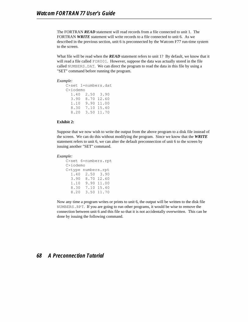
Watcom FORTRAN 77 User’s Guide
The FORTRAN READ statement will read records from a file connected to unit 1. TheFORTRAN WRITE statement will write records to a file connected to unit 6. As wedescribed in the previous section, unit 6 is preconnected by the Watcom F77 run-time systemto the screen.
What file will be read when the READ statement refers to unit 1? By default, we know that itwill read a file called FOR001. However, suppose the data was actually stored in the filecalled NUMBERS.DAT. We can direct the program to read the data in this file by using a"SET" command before running the program.
Example:C>set 1=numbers.datC>iodemo
1.40 2.50 3.903.90 8.70 12.601.10 9.90 11.008.30 7.10 15.408.20 3.50 11.70
Exhibit 2:
Suppose that we now wish to write the output from the above program to a disk file instead ofthe screen. We can do this without modifying the program. Since we know that the WRITEstatement refers to unit 6, we can alter the default preconnection of unit 6 to the screen byissuing another "SET" command.
Example:C>set 6=numbers.rptC>iodemoC>type numbers.rpt
1.40 2.50 3.903.90 8.70 12.601.10 9.90 11.008.30 7.10 15.408.20 3.50 11.70
Now any time a program writes or prints to unit 6, the output will be written to the disk fileNUMBERS.RPT. If you are going to run other programs, it would be wise to remove theconnection between unit 6 and this file so that it is not accidentally overwritten. This can bedone by issuing the following command.
68 A Preconnection Tutorial

Watcom FORTRAN 77 File Handling
Example:C>set 6=
You should also do the same for unit 1.
Exhibit 3:
Must we always use "SET" commands to establish the connection between a unit and a file?Suppose that you want to run the program quite often and that you do not want to issue "SET"commands every time. We can do this by modifying the program to include FORTRANOPEN statements.
* File ’IODEMO.FOR’
OPEN( 1, FILE=’NUMBERS.DAT’ )OPEN( 6, FILE=’NUMBERS.RPT’ )
10 READ( 1, *, END=99 ) X1, X2WRITE( 6, 20 ) X1, X2, X1 + X2GO TO 10
20 FORMAT( 3F6.2 )99 END
This is an example of a connection that is established at execution time. The connection thatis established by the OPEN statement overrides any preconnection that we might haveestablished using a "SET" command. We say that the OPEN statement has a higherprecedence. However, even the OPEN statement does not have the final word on which fileswill be accessed. You may wish to read the next section on the Watcom F77 run-time systemlogical file name support to find out why this is so.
6.8 Logical File Name SupportThe Watcom F77 run-time system supports logical or symbolic file names using the "SET"command. The "SET" command may be used to define a logical file name and itscorresponding actual file name. The format for defining a logical file name is as follows:
SET name=file spec
where description:
name is any character string. The letters in "name" may be specified in upper or lowercase. Lower case letters are treated as if they had been specified in upper case.Thus "SYSINPUT" and "sysinput" are equivalent. Note, however, that blankcharacters must not be specified before and after the "=" character.
Logical File Name Support 69
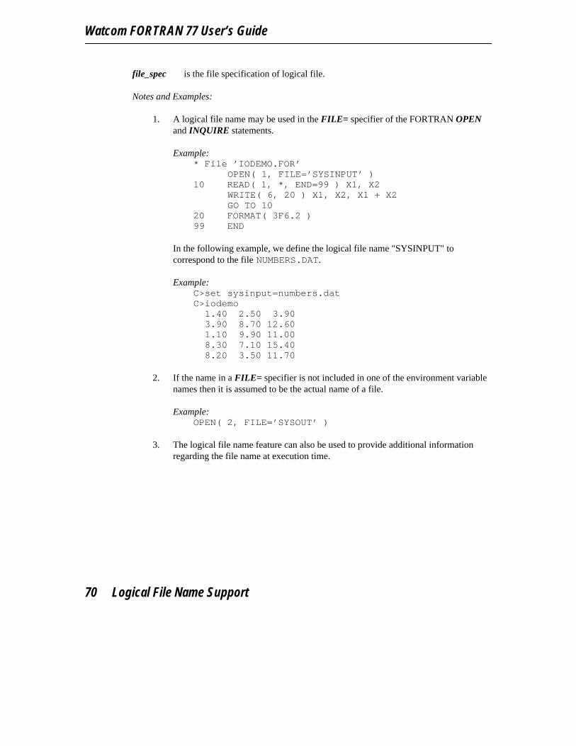
Watcom FORTRAN 77 User’s Guide
file_spec is the file specification of logical file.
Notes and Examples:
1. A logical file name may be used in the FILE= specifier of the FORTRAN OPENand INQUIRE statements.
Example:* File ’IODEMO.FOR’
OPEN( 1, FILE=’SYSINPUT’ )10 READ( 1, *, END=99 ) X1, X2
WRITE( 6, 20 ) X1, X2, X1 + X2GO TO 10
20 FORMAT( 3F6.2 )99 END
In the following example, we define the logical file name "SYSINPUT" tocorrespond to the file NUMBERS.DAT.
Example:C>set sysinput=numbers.datC>iodemo
1.40 2.50 3.903.90 8.70 12.601.10 9.90 11.008.30 7.10 15.408.20 3.50 11.70
2. If the name in a FILE= specifier is not included in one of the environment variablenames then it is assumed to be the actual name of a file.
Example:OPEN( 2, FILE=’SYSOUT’ )
3. The logical file name feature can also be used to provide additional informationregarding the file name at execution time.
70 Logical File Name Support

Watcom FORTRAN 77 File Handling
Example:* File ’IODEMO.FOR’
OPEN( 1, FILE=’NUMBERS.DAT’ )10 READ( 1, *, END=99 ) X1, X2
WRITE( 6, 20 ) X1, X2, X1 + X2GO TO 10
20 FORMAT( 3F6.2 )99 END
In the following example, the actual location (and name) of the fileNUMBERS.DAT is described through the use of an environment variable.
Example:C>set numbers.dat=b:\data\input.datC>iodemo
As you can see, a logical file name can resemble an actual file name.
Of course, the entire file name could have been specified in the FORTRANprogram.
Example:OPEN( 1, FILE=’B:\DATA\INPUT.DAT’ )
4. Only one level of lookup is performed.
Example:* File ’IODEMO.FOR’
OPEN( 1, FILE=’SYSINPUT’ )10 READ( 1, *, END=99 ) X1, X2
WRITE( 6, 20 ) X1, X2, X1 + X2GO TO 10
20 FORMAT( 3F6.2 )99 END
This is illustrated by the following commands.
Logical File Name Support 71
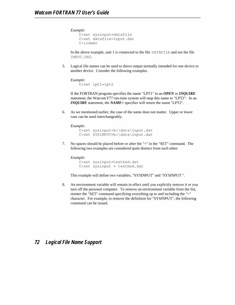
Watcom FORTRAN 77 User’s Guide
Example:C>set sysinput=datafileC>set datafile=input.datC>iodemo
In the above example, unit 1 is connected to the file DATAFILE and not the fileINPUT.DAT.
5. Logical file names can be used to direct output normally intended for one device toanother device. Consider the following examples.
Example:C>set lpt1=lpt2
If the FORTRAN program specifies the name "LPT1" in an OPEN or INQUIREstatement, the Watcom F77 run-time system will map this name to "LPT2". In anINQUIRE statement, the NAME= specifier will return the name "LPT2".
6. As we mentioned earlier, the case of the name does not matter. Upper or lowercase can be used interchangeably.
Example:C>set sysinput=b:\data\input.datC>set SYSINPUT=b:\data\input.dat
7. No spaces should be placed before or after the "=" in the "SET" command. Thefollowing two examples are considered quite distinct from each other:
Example:C>set sysinput=testbed.datC>set sysinput = testbed.dat
This example will define two variables, "SYSINPUT" and "SYSINPUT ".
8. An environment variable will remain in effect until you explicitly remove it or youturn off the personal computer. To remove an environment variable from the list,reenter the "SET" command specifying everything up to and including the "="character. For example, to remove the definition for "SYSINPUT", the followingcommand can be issued.
72 Logical File Name Support
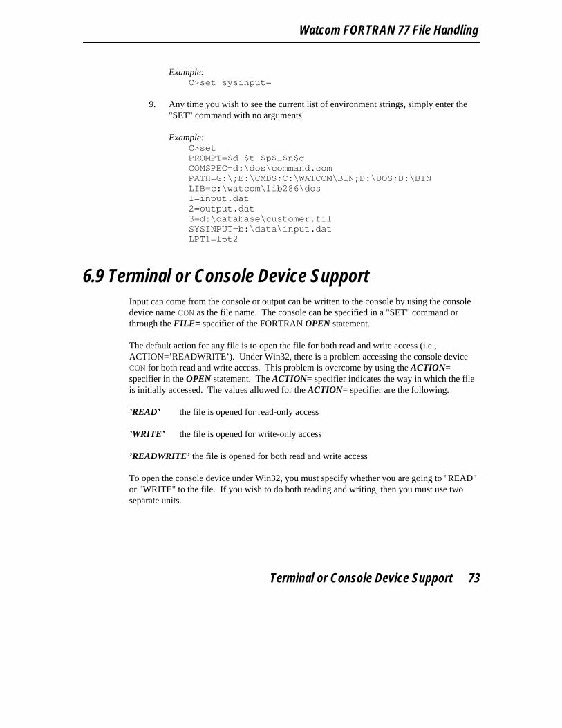
Watcom FORTRAN 77 File Handling
Example:C>set sysinput=
9. Any time you wish to see the current list of environment strings, simply enter the"SET" command with no arguments.
Example:C>setPROMPT=$d $t $p$ $n$gCOMSPEC=d:\dos\command.comPATH=G:\;E:\CMDS;C:\WATCOM\BIN;D:\DOS;D:\BINLIB=c:\watcom\lib286\dos1=input.dat2=output.dat3=d:\database\customer.filSYSINPUT=b:\data\input.datLPT1=lpt2
6.9 Terminal or Console Device SupportInput can come from the console or output can be written to the console by using the consoledevice name CON as the file name. The console can be specified in a "SET" command orthrough the FILE= specifier of the FORTRAN OPEN statement.
The default action for any file is to open the file for both read and write access (i.e.,ACTION=’READWRITE’). Under Win32, there is a problem accessing the console deviceCON for both read and write access. This problem is overcome by using the ACTION=specifier in the OPEN statement. The ACTION= specifier indicates the way in which the fileis initially accessed. The values allowed for the ACTION= specifier are the following.
’READ’ the file is opened for read-only access
’WRITE’ the file is opened for write-only access
’READWRITE’ the file is opened for both read and write access
To open the console device under Win32, you must specify whether you are going to "READ"or "WRITE" to the file. If you wish to do both reading and writing, then you must use twoseparate units.
Terminal or Console Device Support 73

Watcom FORTRAN 77 User’s Guide
Example:OPEN( UNIT=1, FILE=’CON’, ACTION=’READ’)OPEN( UNIT=2, FILE=’CON’, ACTION=’WRITE’)
The console can be treated as a carriage control device. This is requested by using theCARRIAGECONTROL=’YES’ specifier of the FORTRAN OPEN statement.
Example:OPEN( UNIT=1, FILE=’CON’, CARRIAGECONTROL=’YES’ )
Carriage control handling is described in the section entitled "Print File Attributes" on page56.
The console is not capable of supporting carriage control in a fashion identical to a printer.For example, overprinting of records on the console is destructive in that the previouscharacters are erased.
End of file is signalled by first pressing the Ctrl/Z key combination and then the line enteringkey. End of file may be handled by using the END= specification of the FORTRAN READstatement.
Example:READ( UNIT=*, FMT=*, END=100 ) X, Y...
100 code to handle "End of File"
End of file may also be handled by using the IOSTAT= specifier of the FORTRAN READstatement.
Example:READ( UNIT=*, FMT=*, IOSTAT=IOS ) X, YIF( IOS .NE. 0 )THENcode to handle "End of File"ENDIF
74 Terminal or Console Device Support

Watcom FORTRAN 77 File Handling
6.10 Printer Device SupportOutput can be written to a printer by using a printer device name as the file name. A printercan be specified in a "SET" command or through the FILE= specifier of the FORTRANOPEN statement. Several device names may be used:
PRN or LPT1LPT2LPT3
The printer can be treated as a carriage control device. This is requested by using theCARRIAGECONTROL=’YES’ specifier of the FORTRAN OPEN statement.
Example:OPEN( UNIT=1, FILE=’PRN’, CARRIAGECONTROL=’YES’ )
Carriage control handling is described in the section entitled "Print File Attributes" on page56.
6.11 Serial Device SupportOutput can be written to a serial port by using a serial device name as the file name. A serialdevice can be specified in a "SET" command or through the FILE= specifier of theFORTRAN OPEN statement. Three device names may be used:
AUX or COM1COM2
The serial device can be treated as a carriage control device. This is requested by using theCARRIAGECONTROL=’YES’ specifier of the FORTRAN OPEN statement.
Example:OPEN( UNIT=1, FILE=’COM1’, CARRIAGECONTROL=’YES’ )
Carriage control handling is described in the section entitled "Print File Attributes" on page56.
To set serial characteristics such as speed, parity, and word length, the "MODE" commandmay be used.
Serial Device Support 75
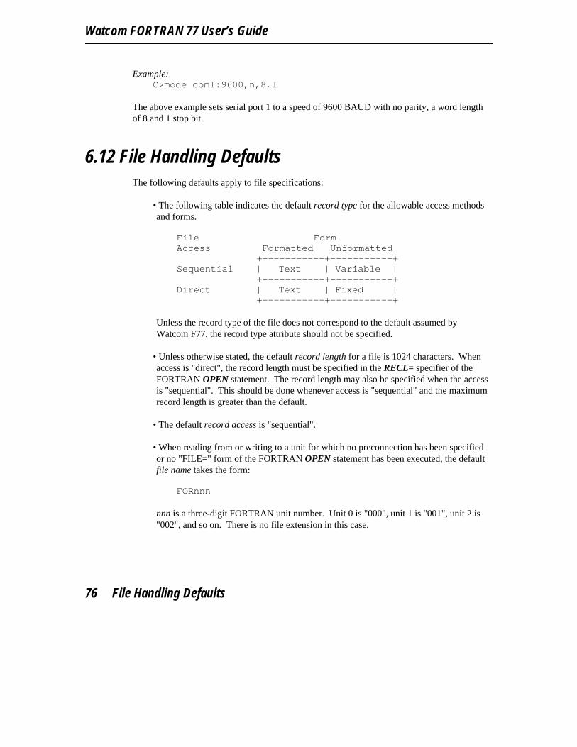
Watcom FORTRAN 77 User’s Guide
Example:C>mode com1:9600,n,8,1
The above example sets serial port 1 to a speed of 9600 BAUD with no parity, a word lengthof 8 and 1 stop bit.
6.12 File Handling DefaultsThe following defaults apply to file specifications:
• The following table indicates the default record type for the allowable access methodsand forms.
File FormAccess Formatted Unformatted
+-----------+-----------+Sequential | Text | Variable |
+-----------+-----------+Direct | Text | Fixed |
+-----------+-----------+
Unless the record type of the file does not correspond to the default assumed byWatcom F77, the record type attribute should not be specified.
• Unless otherwise stated, the default record length for a file is 1024 characters. Whenaccess is "direct", the record length must be specified in the RECL= specifier of theFORTRAN OPEN statement. The record length may also be specified when the accessis "sequential". This should be done whenever access is "sequential" and the maximumrecord length is greater than the default.
• The default record access is "sequential".
• When reading from or writing to a unit for which no preconnection has been specifiedor no "FILE=" form of the FORTRAN OPEN statement has been executed, the defaultfile name takes the form:
FORnnn
nnn is a three-digit FORTRAN unit number. Unit 0 is "000", unit 1 is "001", unit 2 is"002", and so on. There is no file extension in this case.
76 File Handling Defaults
Watcom FORTRAN 77 File Handling
• If the connection between a unit number and a file is discontinued through use of theFORTRAN CLOSE statement, the same rule for constructing a file name will apply onthe next attempt to read from or write to the specified unit.
File Handling Defaults 77

Watcom FORTRAN 77 User’s Guide
78 File Handling Defaults

7 The Watcom F77 Subprogram Library
Watcom FORTRAN 77 includes additional FORTRAN subprograms which can be calledfrom programs compiled by Watcom F77. The following sections describe thesesubprograms.
7.1 Subroutine FEXITThe subroutine FEXIT allows an application to terminate execution with a return code. Itrequires one argument of type INTEGER that represents the value to be returned to thesystem.
Example:INCLUDE ’FSUBLIB.FI’CALL FEXIT( -1 )END
Notes:
1. The FORTRAN include file FSUBLIB.FI, located in the\WATCOM\SRC\FORTRAN directory, contains typing and calling information forthis subprogram. The \WATCOM\SRC\FORTRAN directory should be included inthe FINCLUDE environment variable so that the compiler can locate the includefile.
7.2 INTEGER Function FGETCMDThe INTEGER function FGETCMD allows an application to obtain the command line fromwithin an executing program.
The function FGETCMD requires one argument of type CHARACTER and returns the lengthof the command line.
INTEGER Function FGETCMD 79

Watcom FORTRAN 77 User’s Guide
Example:INCLUDE ’FSUBLIB.FI’INTEGER CMDLENCHARACTER*128 CMDLIN
CMDLEN = FGETCMD( CMDLIN )PRINT *, ’Command length = ’, CMDLENPRINT *, ’Command line = ’, CMDLINEND
Notes:
1. The FORTRAN include file FSUBLIB.FI, located in the\WATCOM\SRC\FORTRAN directory, contains typing and calling information forthis subprogram. The \WATCOM\SRC\FORTRAN directory should be included inthe FINCLUDE environment variable so that the compiler can locate the includefile.
2. If the argument to FGETCMD is not long enough then only the first part of thecommand line is returned.
7.3 INTEGER Function FGETENVThe INTEGER function FGETENV allows an application to obtain the value of anenvironment string from within an executing program.
The function FGETENV requires two arguments of type CHARACTER. The first argument isthe character string to look for. FGETENV places the associated environment string value inthe second argument and returns the length of the environment string. If no such string isdefined, the length returned is zero.
Example:INCLUDE ’FSUBLIB.FI’INTEGER STRLENCHARACTER*80 STRVAL
STRLEN = FGETENV( ’PATH’, STRVAL )PRINT *, ’Environment string length = ’, STRLENPRINT *, ’Environment string value = ’, STRVALEND
80 INTEGER Function FGETENV

The Watcom F77 Subprogram Library
Notes:
1. The FORTRAN include file FSUBLIB.FI, located in the\WATCOM\SRC\FORTRAN directory, contains typing and calling information forthis subprogram. The \WATCOM\SRC\FORTRAN directory should be included inthe FINCLUDE environment variable so that the compiler can locate the includefile.
2. If the second argument to FGETENV is not long enough then only the first part ofthe value is returned.
7.4 INTEGER Function FILESIZEThe INTEGER function FILESIZE allows an application to determine the size of a fileconnected to a specified unit.
The function FILESIZE requires one argument of type INTEGER, the unit number andreturns the size, in bytes, of the file. If no file is connected to the specified unit, a value of -1is returned.
Example:INCLUDE ’FSUBLIB.FI’
OPEN( UNIT=1, FILE=’SAMPLE.FIL’ )PRINT *, FILESIZE( 1 )END
Notes:
1. The FORTRAN include file FSUBLIB.FI, located in the\WATCOM\SRC\FORTRAN directory, contains typing and calling information forthis subprogram. The \WATCOM\SRC\FORTRAN directory should be included inthe FINCLUDE environment variable so that the compiler can locate the includefile.
INTEGER Function FILESIZE 81

Watcom FORTRAN 77 User’s Guide
7.5 Subroutine FINTRThe subroutine FINTR allows the user to execute any software interrupt from a FORTRAN77 program.
Note: This subroutine is only supported by the DOS and Windows libraries.
The subroutine FINTR requires two arguments.
1. The first argument is an interrupt number. The subroutine FINTR will generate thesoftware interrupt given by the first argument. The type of this argument must beINTEGER.
2. The second argument is an INTEGER array of ten elements.
When FINTR is called, the array contains the values to be assigned to the registers prior toissuing the software interrupt. When control is returned from FINTR, it contains the valuesof the registers after the software interrupt has completed. The registers are mapped onto thearray REGS as follows.
31 0
REGS(1) EAXREGS(2) EBXREGS(3) ECXREGS(4) EDXREGS(5) EBPREGS(6) ESIREGS(7) EDIREGS(8) FS | DSREGS(9) GS | ESREGS(10) eflags
For 16-bit systems (e.g., 8088, 8086, 186, 286), only the low-order 16 bits of each registercontain meaningful results.
82 Subroutine FINTR

The Watcom F77 Subprogram Library
31 0
REGS(1) AXREGS(2) BXREGS(3) CXREGS(4) DXREGS(5) BPREGS(6) SIREGS(7) DIREGS(8) DSREGS(9) ESREGS(10) flags
The file DOS.FI, located in the \WATCOM\SRC\FORTRAN\DOS directory, defines a set ofequivalences for ease of use. The contents of this file are reproduced below.
* Define registers: These correspond to the element of an* array which is to contain the values of the registers.
integer*4 regd(10), regs(10)integer*2 regw(2*10)integer*1 regb(4*4)
integer*4 EAX,EBX,ECX,EDX,EBP,EDI,ESI,EFLAGSinteger*2 AX,BX,CX,DX,BP,DI,SI,DS,ES,FS,GS,FLAGSinteger*1 AH,AL,BH,BL,CH,CL,DH,DLequivalence (regd,regs),(regd,regw),(regd,regb),
1(EAX,regd(1)), (EBX,regd(2)), (ECX,regd(3)), (EDX,regd(4)),2(EBP,regd(5)), (EDI,regd(6)), (ESI,regd(7)), (EFLAGS,regd(10)),3(AX,regw(1)), (BX,regw(3)), (CX,regw(5)), (DX,regw(7)),4(BP,regw(9)), (DI,regw(11)), (SI,regw(13)), (DS,regw(15)),5(FS,regw(16)), (ES,regw(17)), (GS,regw(18)), (FLAGS,regw(19)),6(AL,regb(1)), (AH,regb(2)), (BL,regb(5)), (BH,regb(6)),7(CL,regb(9)), (CH,regb(10)), (DL,regb(13)), (DH,regb(14))
The following is extracted from the "CALENDAR" program. It demonstrates the use of theFINTR subroutine.
Subroutine FINTR 83
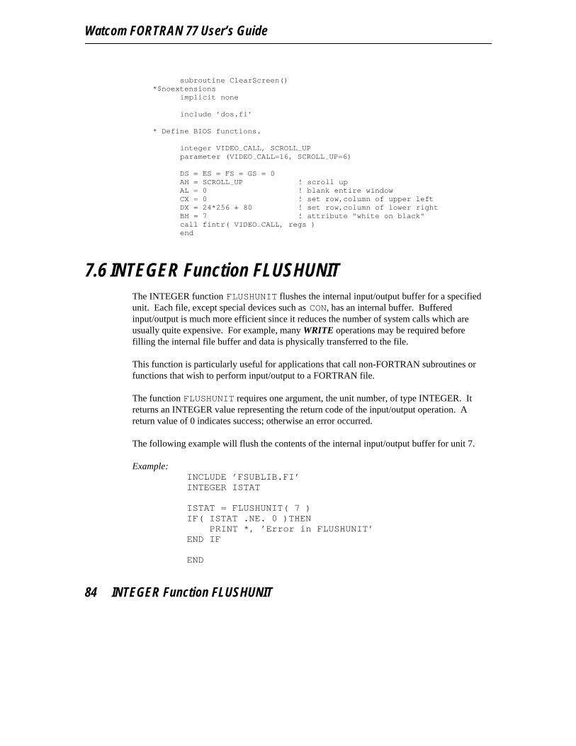
Watcom FORTRAN 77 User’s Guide
subroutine ClearScreen()
*$noextensionsimplicit none
include ’dos.fi’
* Define BIOS functions.
integer VIDEO CALL, SCROLL UPparameter (VIDEO CALL=16, SCROLL UP=6)
DS = ES = FS = GS = 0AH = SCROLL UP ! scroll upAL = 0 ! blank entire windowCX = 0 ! set row,column of upper leftDX = 24*256 + 80 ! set row,column of lower rightBH = 7 ! attribute "white on black"call fintr( VIDEO CALL, regs )end
7.6 INTEGER Function FLUSHUNITThe INTEGER function FLUSHUNIT flushes the internal input/output buffer for a specifiedunit. Each file, except special devices such as CON, has an internal buffer. Bufferedinput/output is much more efficient since it reduces the number of system calls which areusually quite expensive. For example, many WRITE operations may be required beforefilling the internal file buffer and data is physically transferred to the file.
This function is particularly useful for applications that call non-FORTRAN subroutines orfunctions that wish to perform input/output to a FORTRAN file.
The function FLUSHUNIT requires one argument, the unit number, of type INTEGER. Itreturns an INTEGER value representing the return code of the input/output operation. Areturn value of 0 indicates success; otherwise an error occurred.
The following example will flush the contents of the internal input/output buffer for unit 7.
Example:INCLUDE ’FSUBLIB.FI’INTEGER ISTAT
ISTAT = FLUSHUNIT( 7 )IF( ISTAT .NE. 0 )THEN
PRINT *, ’Error in FLUSHUNIT’END IF
END
84 INTEGER Function FLUSHUNIT
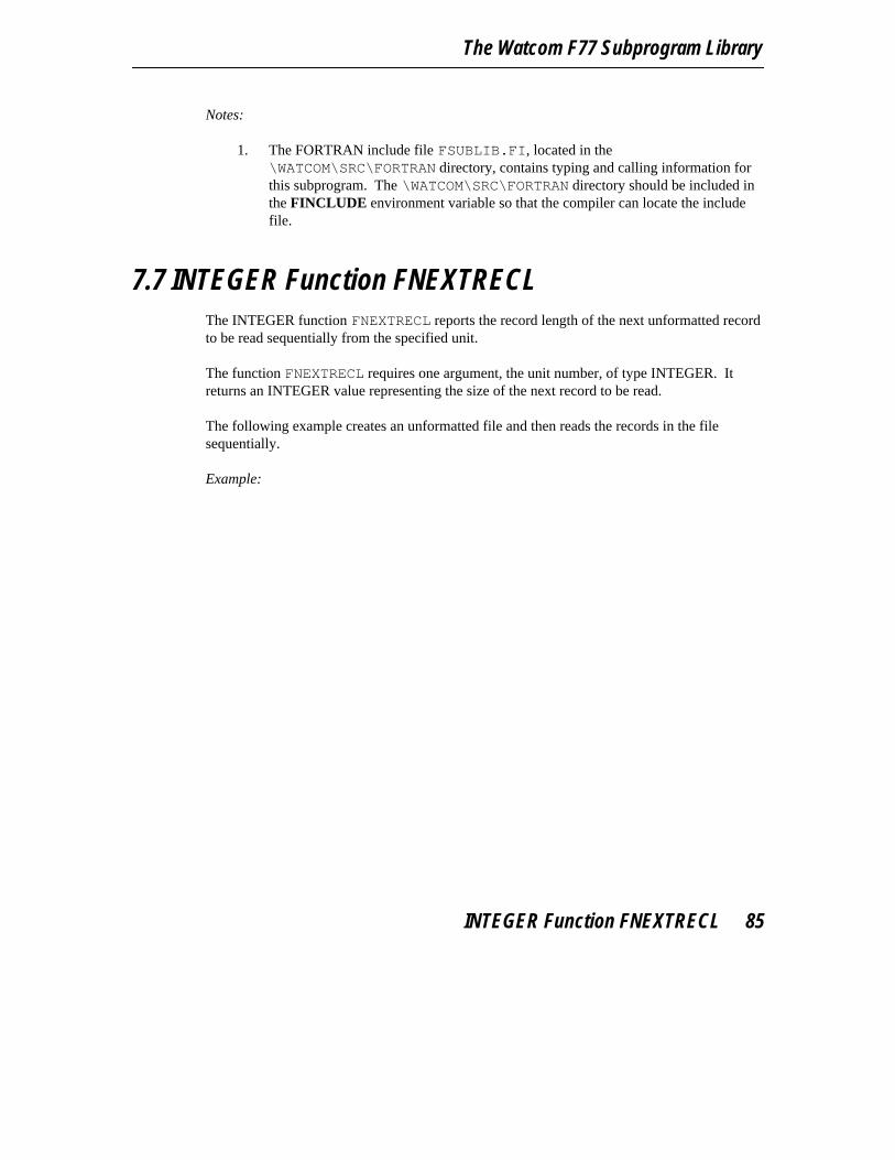
The Watcom F77 Subprogram Library
Notes:
1. The FORTRAN include file FSUBLIB.FI, located in the\WATCOM\SRC\FORTRAN directory, contains typing and calling information forthis subprogram. The \WATCOM\SRC\FORTRAN directory should be included inthe FINCLUDE environment variable so that the compiler can locate the includefile.
7.7 INTEGER Function FNEXTRECLThe INTEGER function FNEXTRECL reports the record length of the next unformatted recordto be read sequentially from the specified unit.
The function FNEXTRECL requires one argument, the unit number, of type INTEGER. Itreturns an INTEGER value representing the size of the next record to be read.
The following example creates an unformatted file and then reads the records in the filesequentially.
Example:
INTEGER Function FNEXTRECL 85

Watcom FORTRAN 77 User’s Guide
INCLUDE ’FSUBLIB.FI’
CHARACTER*80 INPUT
OPEN(UNIT=2, FILE=’UNFORM.TXT’, FORM=’UNFORMATTED’,& ACCESS=’SEQUENTIAL’ )WRITE( UNIT=2 ) ’A somewhat longish first record’WRITE( UNIT=2 ) ’A short second record’WRITE( UNIT=2 ) ’A very, very much longer third
record’CLOSE( UNIT=2 )
OPEN(UNIT=2, FILE=’UNFORM.TXT’, FORM=’UNFORMATTED’,& ACCESS=’SEQUENTIAL’ )
I = FNEXTRECL( 2 )PRINT *, ’Record length=’, IREAD( UNIT=2 ) INPUT(1:I)PRINT *, INPUT(1:I)
I = FNEXTRECL( 2 )PRINT *, ’Record length=’, IREAD( UNIT=2 ) INPUT(1:I)PRINT *, INPUT(1:I)
I = FNEXTRECL( 2 )PRINT *, ’Record length=’, IREAD( UNIT=2 ) INPUT(1:I)PRINT *, INPUT(1:I)CLOSE( UNIT=2 )END
Notes:
1. The FORTRAN include file FSUBLIB.FI, located in the\WATCOM\SRC\FORTRAN directory, contains typing and calling information forthis subprogram. The \WATCOM\SRC\FORTRAN directory should be included inthe FINCLUDE environment variable so that the compiler can locate the includefile.
86 INTEGER Function FNEXTRECL

The Watcom F77 Subprogram Library
7.8 INTEGER Function FSIGNALThe INTEGER function FSIGNAL allows your application to respond to certain events thatoccur during execution.
Event Meaning
SIGBREAK an interactive attention (Ctrl/Break on keyboard) is signalled
SIGFPE an erroneous floating-point operation occurs (such as division by zero,overflow and underflow)
SIGILL illegal instruction encountered
SIGINT an interactive attention (Ctrl/C on keyboard) is signalled
SIGSEGV an illegal memory reference is detected
SIGTERM a termination request is sent to the program
SIGIDIVZ integer division by zero
SIGIOVFL integer overflow
The function FSIGNAL requires two arguments. The first argument is an INTEGERargument and must be one of the events described above. The second argument, called thehandler, is one of the following.
1. a subprogram that is called when the event occurs2. the value SIG_DFL, causing the default action to be taken when the event occurs3. the value SIG_IGN, causing the event to be ignored
FSIGNAL returns SIG_ERR if the request could not be processed, or the previous eventhandler.
INTEGER Function FSIGNAL 87

Watcom FORTRAN 77 User’s Guide
Example:INCLUDE ’FSIGNAL.FI’
EXTERNAL BREAK HANDLERLOGICAL BREAK FLAGCOMMON BREAK FLAGBREAK FLAG = .FALSE.CALL FSIGNAL( SIGBREAK, BREAK HANDLER )WHILE( .NOT. VOLATILE( BREAK FLAG ) ) CONTINUEPRINT *, ’Program Interrupted’END
SUBROUTINE BREAK HANDLER()LOGICAL BREAK FLAGCOMMON BREAK FLAGBREAK FLAG = .TRUE.END
Notes:
1. The FORTRAN include file FSIGNAL.FI contains typing and calling informationfor FSIGNAL and should be included when using this function. This file is locatedin the \WATCOM\SRC\FORTRAN directory. The \WATCOM\SRC\FORTRANdirectory should be included in the FINCLUDE environment variable so that thecompiler can locate the include file.
2. The intrinsic function VOLATILE is used to indicate that the reference to thevariable break flag is volatile. A volatile reference prevents the compiler fromcaching a variable in a register. In this case, we want to retrieve the value ofbreak flag from memory each time the loop is iterated.
7.9 INTEGER Function FSPAWNThe INTEGER function FSPAWN allows an application to run another program as asubprocess. When the program completes, execution is returned to the invoking application.There must be enough available free memory to start the subprocess.
The function FSPAWN requires two arguments of type CHARACTER. The first argument is acharacter string representing the name of the program to be run. The string must end in aNULL character (i.e., a character with the binary value 0).
The second argument is a character string argument list to be passed to the program. The firstcharacter of the second argument must contain, in binary, the length of the remainder of the
88 INTEGER Function FSPAWN

The Watcom F77 Subprogram Library
argument list. For example, if the argument is the string "HELLO" then the first characterwould be CHAR(5) and the remaining characters would be "HELLO" (see the examplebelow).
FSPAWN returns an INTEGER value representing the status of subprocess execution. If thevalue is negative then the program could not be run. If the value is positive then the valuerepresents the program’s return code.
Example:INCLUDE ’FSUBLIB.FI’INTEGER CMDLEN, STATUSCHARACTER CMD*128, CMDLIN*128
* COMSPEC will tell us where DOS ’COMMAND.COM’ is hidingCMDLEN = FGETENV( ’COMSPEC’, CMD )CMD(CMDLEN+1:CMDLEN+1) = CHAR( 0 )
CMDLIN = ’/c dir *.for’CMDLIN(13:13) = CHAR( 0 )
STATUS = FSPAWN( CMD, CMDLIN )PRINT *, ’Program status = ’, STATUSEND
Notes:
1. The FORTRAN include file FSUBLIB.FI, located in the\WATCOM\SRC\FORTRAN directory, contains typing and calling information forthis subprogram. The \WATCOM\SRC\FORTRAN directory should be included inthe FINCLUDE environment variable so that the compiler can locate the includefile.
2. The INTEGER function FSYSTEM, which is described in a later section,implements a more general form of the example given above. We recommend itsuse.
7.10 INTEGER Function FSYSTEMThe INTEGER function FSYSTEM allows an application to run another program or executean operating system command.
The function FSYSTEM requires one argument of type CHARACTER. This argumentrepresents a operating system command or a program name together with any arguments.
INTEGER Function FSYSTEM 89
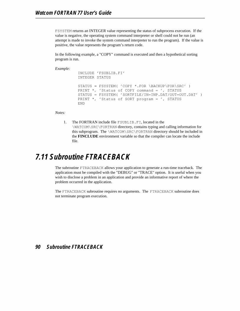
Watcom FORTRAN 77 User’s Guide
FSYSTEM returns an INTEGER value representing the status of subprocess execution. If thevalue is negative, the operating system command interpreter or shell could not be run (anattempt is made to invoke the system command interpreter to run the program). If the value ispositive, the value represents the program’s return code.
In the following example, a "COPY" command is executed and then a hypothetical sortingprogram is run.
Example:INCLUDE ’FSUBLIB.FI’INTEGER STATUS
STATUS = FSYSTEM( ’COPY *.FOR \BACKUP\FOR\SRC’ )PRINT *, ’Status of COPY command = ’, STATUSSTATUS = FSYSTEM( ’SORTFILE/IN=INP.DAT/OUT=OUT.DAT’ )PRINT *, ’Status of SORT program = ’, STATUSEND
Notes:
1. The FORTRAN include file FSUBLIB.FI, located in the\WATCOM\SRC\FORTRAN directory, contains typing and calling information forthis subprogram. The \WATCOM\SRC\FORTRAN directory should be included inthe FINCLUDE environment variable so that the compiler can locate the includefile.
7.11 Subroutine FTRACEBACKThe subroutine FTRACEBACK allows your application to generate a run-time traceback. Theapplication must be compiled with the "DEBUG" or "TRACE" option. It is useful when youwish to disclose a problem in an application and provide an informative report of where theproblem occurred in the application.
The FTRACEBACK subroutine requires no arguments. The FTRACEBACK subroutine doesnot terminate program execution.
90 Subroutine FTRACEBACK
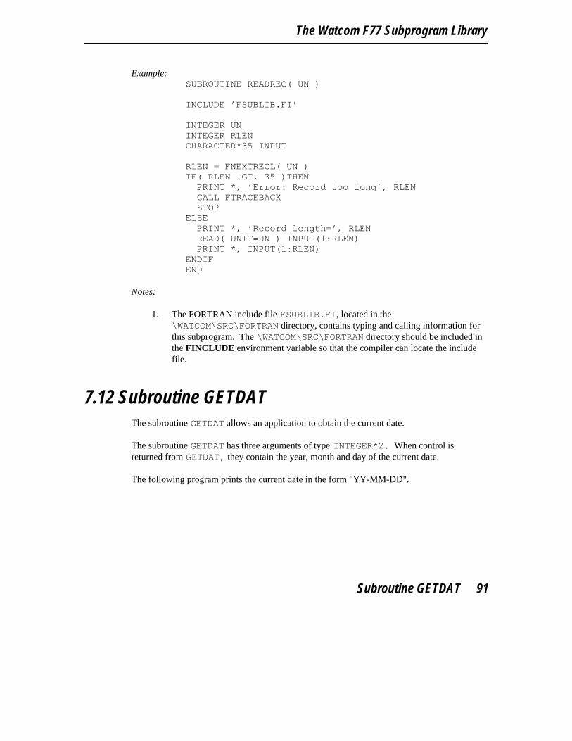
The Watcom F77 Subprogram Library
Example:SUBROUTINE READREC( UN )
INCLUDE ’FSUBLIB.FI’
INTEGER UNINTEGER RLENCHARACTER*35 INPUT
RLEN = FNEXTRECL( UN )IF( RLEN .GT. 35 )THEN
PRINT *, ’Error: Record too long’, RLENCALL FTRACEBACKSTOP
ELSEPRINT *, ’Record length=’, RLENREAD( UNIT=UN ) INPUT(1:RLEN)PRINT *, INPUT(1:RLEN)
ENDIFEND
Notes:
1. The FORTRAN include file FSUBLIB.FI, located in the\WATCOM\SRC\FORTRAN directory, contains typing and calling information forthis subprogram. The \WATCOM\SRC\FORTRAN directory should be included inthe FINCLUDE environment variable so that the compiler can locate the includefile.
7.12 Subroutine GETDATThe subroutine GETDAT allows an application to obtain the current date.
The subroutine GETDAT has three arguments of type INTEGER*2. When control isreturned from GETDAT, they contain the year, month and day of the current date.
The following program prints the current date in the form "YY-MM-DD".
Subroutine GETDAT 91
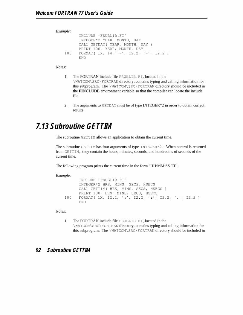
Watcom FORTRAN 77 User’s Guide
Example:INCLUDE ’FSUBLIB.FI’INTEGER*2 YEAR, MONTH, DAYCALL GETDAT( YEAR, MONTH, DAY )PRINT 100, YEAR, MONTH, DAY
100 FORMAT( 1X, I4, ’-’, I2.2, ’-’, I2.2 )END
Notes:
1. The FORTRAN include file FSUBLIB.FI, located in the\WATCOM\SRC\FORTRAN directory, contains typing and calling information forthis subprogram. The \WATCOM\SRC\FORTRAN directory should be included inthe FINCLUDE environment variable so that the compiler can locate the includefile.
2. The arguments to GETDAT must be of type INTEGER*2 in order to obtain correctresults.
7.13 Subroutine GETTIMThe subroutine GETTIM allows an application to obtain the current time.
The subroutine GETTIM has four arguments of type INTEGER*2. When control is returnedfrom GETTIM, they contain the hours, minutes, seconds, and hundredths of seconds of thecurrent time.
The following program prints the current time in the form "HH:MM:SS.TT".
Example:INCLUDE ’FSUBLIB.FI’INTEGER*2 HRS, MINS, SECS, HSECSCALL GETTIM( HRS, MINS, SECS, HSECS )PRINT 100, HRS, MINS, SECS, HSECS
100 FORMAT( 1X, I2.2, ’:’, I2.2, ’:’, I2.2, ’.’, I2.2 )END
Notes:
1. The FORTRAN include file FSUBLIB.FI, located in the\WATCOM\SRC\FORTRAN directory, contains typing and calling information forthis subprogram. The \WATCOM\SRC\FORTRAN directory should be included in
92 Subroutine GETTIM

The Watcom F77 Subprogram Library
the FINCLUDE environment variable so that the compiler can locate the includefile.
2. The arguments to GETTIM must be of type INTEGER*2 in order to obtain correctresults.
7.14 INTEGER Function GROWHANDLESThe INTEGER function GROWHANDLES allows an application to increase the maximumnumber of files that can be opened. It requires one argument of type INTEGER representingthe maximum number of files that can be opened and returns an INTEGER value representingthe actual limit. The actual limit may differ from the specified limit. For example, memoryconstraints or system parameters may be such that the request cannot be satisfied.
The following example attempts to increase the limit on the number of open files to sixty-four.
Example:INCLUDE ’FSUBLIB.FI’INTEGER NEW LIMIT
NEW LIMIT = GROWHANDLES( 64 )
END
Notes:
1. The FORTRAN include file FSUBLIB.FI, located in the\WATCOM\SRC\FORTRAN directory, contains typing and calling information forthis subprogram. The \WATCOM\SRC\FORTRAN directory should be included inthe FINCLUDE environment variable so that the compiler can locate the includefile.
7.15 Functions IARGC and IGETARGThe function IARGC allows an application to determine the number of arguments (includingthe program name) used to invoke the program. The function IGETARG can be used toretrieve an argument.
Arguments supplied to a program are assigned indices. Argument zero is the program name,argument one is the first argument, etc. The function IGETARG requires two arguments. Thefirst argument is the index of the argument to retrieve and is of type INTEGER. The second
Functions IARGC and IGETARG 93

Watcom FORTRAN 77 User’s Guide
argument is of type CHARACTER and is used to return the argument. The size of theargument (number of characters) is returned.
Example:INCLUDE ’FSUBLIB.FI’CHARACTER*128 ARGINTEGER ARGC, ARGLEN
ARGC = IARGC()ARGLEN = IGETARG( 0, ARG )PRINT *, ’Program name is ’, ARG(1:ARGLEN)DO I = 1, ARGC - 1
ARGLEN = IGETARG( I, ARG )PRINT ’(A, I2, 2A)’, ’Argument ’, I, ’ is ’,
1 ARG(1:ARGLEN)END DOEND
Notes:
1. The FORTRAN include file FSUBLIB.FI, located in the\WATCOM\SRC\FORTRAN directory, contains typing and calling information forthis subprogram. The \WATCOM\SRC\FORTRAN directory should be included inthe FINCLUDE environment variable so that the compiler can locate the includefile.
7.16 Math Error FunctionsMath error functions are called when an error is detected in a math library function. Forexample, if the second argument to the AMOD intrinsic function is zero, a math error functionwill be called. A number of math error functions are defined in the FORTRAN run-timelibraries and perform default actions when an error is detected. These actions typicallyproduce an error message to the screen.
It is possible to replace the FORTRAN run-time library version of the math error functionswith your own versions. The file MATHERR.FOR located in the\WATCOM\SRC\FORTRAN directory can be used as a template for defining your own matherror functions. The following functions represent the set of math error functions.
1. The function imath2err is called for math functions of type INTEGER thattake two arguments of type INTEGER. The first argument represents the errorinformation and is an argument of type INTEGER that is passed by value. Thesecond argument is a pointer to the first argument passed to the math function and
94 Math Error Functions

The Watcom F77 Subprogram Library
the third argument is a pointer to the second argument passed to the math function.The error function returns a value that is then used as the return value for the mathfunction.
2. The function amath1err is called for math functions of type REAL that takeone argument of type REAL. The first argument represents the error informationand is an argument of type INTEGER that is passed by value. The secondargument is a pointer to the argument passed to the math function. The errorfunction returns a value that is then used as the return value for the math function.
3. The function amath2err is called for math functions of type REAL that taketwo arguments of type REAL. The first argument represents the error informationand is an argument of type INTEGER that is passed by value. The secondargument is a pointer to the first argument passed to the math function and the thirdargument is a pointer to the second argument passed to the math function. Theerror function returns a value that is then used as the return value for the mathfunction.
4. The function math1err is called for math functions of type DOUBLEPRECISION that take one argument of type DOUBLE PRECISION. The firstargument represents the error information and is an argument of type INTEGERthat is passed by value. The second argument is a pointer to the argument passed tothe math function. The error function returns a value that is then used as the returnvalue for the math function.
5. The function math2err is called for math functions of type DOUBLEPRECISION that take two arguments of type DOUBLE PRECISION. The firstargument represents the error information and is an argument of type INTEGERthat is passed by value. The second argument is a pointer to the first argumentpassed to the math function and the third argument is a pointer to the secondargument passed to the math function. The error function returns a value that isthen used as the return value for the math function.
6. The function zmath2err is called for math functions of type COMPLEX thattake two arguments of type COMPLEX. The first argument represents the errorinformation and is an argument of type INTEGER that is passed by value. Thesecond argument is a pointer to the first argument passed to the math function andthe third argument is a pointer to the second argument passed to the math function.The error function returns a value that is then used as the return value for the mathfunction.
7. The function qmath2err is called for math functions of type DOUBLECOMPLEX that take two arguments of type DOUBLE COMPLEX. The firstargument represents the error information and is an argument of type INTEGERthat is passed by value. The second argument is a pointer to the first argumentpassed to the math function and the third argument is a pointer to the secondargument passed to the math function. The error function returns a value that isthen used as the return value for the math function.
Math Error Functions 95

Watcom FORTRAN 77 User’s Guide
The include file MATHCODE.FI is included by the file MATHERR.FOR and is located in the\WATCOM\SRC\FORTRAN directory. It defines the information that is contained in the errorinformation argument that is passed to all math error functions.
7.17 INTEGER Function SEEKUNITThe INTEGER function SEEKUNIT permits seeking to a particular byte offset within a fileconnected to a FORTRAN unit. The file must be opened with the following attributes:
FORM=’UNFORMATTED’ACCESS=’SEQUENTIAL’RECORDTYPE=’FIXED’
The function SEEKUNIT requires three arguments of type INTEGER, the unit number, theoffset to seek, and the type of positioning to do. The seek positioning may be absolute(indicated by 0) or relative to the current position (indicated by 1). It returns an INTEGERvalue representing the new offset in the file. A returned value of -1 indicates that the functioncall failed.
This function is particularly useful for applications that wish to change the input/outputposition for a file connected to a unit.
The following example will set the current input/output position of the file connected to thespecified unit.
Example:EXTERNAL SEEKUNITINTEGER SEEKUNITINTEGER SEEK SET, SEEK CURPARAMETER (SEEK SET=0, SEEK CUR=1)
INTEGER POSITIONCHARACTER*80 RECORD
OPEN( UNIT=8, FILE=’file’, FORM=’UNFORMATTED’,1 ACCESS=’SEQUENTIAL’, RECORDTYPE=’FIXED’ )POSITION = SEEKUNIT( 8, 10, SEEK SET )IF( POSITION .NE. -1 )THEN
PRINT *, ’New position is’, POSITIONREAD( UNIT=8 ) RECORDPRINT *, RECORD
ENDIFEND
96 INTEGER Function SEEKUNIT
The Watcom F77 Subprogram Library
Notes:
1. The FORTRAN include file FSUBLIB.FI, located in the\WATCOM\SRC\FORTRAN directory, contains typing and calling information forthis subprogram. The \WATCOM\SRC\FORTRAN directory should be included inthe FINCLUDE environment variable so that the compiler can locate the includefile.
2. A value of -1 is returned if the requested positioning cannot be done.
7.18 INTEGER Function SETJMP/SubroutineLONGJMP
The INTEGER function SETJMP saves the current executing environment, making it possibleto restore that environment by subsequently calling the LONGJMP subroutine. For example, itis possible to implement error handling by using SETJMP to record the point to which areturn will occur following an error. When an error is detected in a called subprogram, thatsubprogram uses LONGJMP to jump back to the recorded position. The original subprogramwhich called SETJMP must still be active (it cannot have returned to the subprogram whichcalled it).
The SETJMP function requires one argument. The argument is a structure of type jmp bufand is used to save the current environment. The return value is an integer and is zero wheninitially called. It is non-zero if the return is the result of a call to the LONGJMP subroutine.An IF statement is often used to handle these two cases. This is demonstrated in thefollowing example.
Example:
INTEGER Function SETJMP/Subroutine LONGJMP 97

Watcom FORTRAN 77 User’s Guide
include ’fsignal.fi’include ’setjmp.fi’record /jmp buf/ jmp bufcommon jmp bufexternal break handlerinteger rccall fsignal( SIGBREAK, break handler )rc = setjmp( jmp buf )if( rc .eq. 0 )then
call do it()else
print *, ’abnormal termination:’, rcendifend
subroutine do it()loopend loopend
subroutine break handler()include ’setjmp.fi’record /jmp buf/ jmp bufcommon jmp bufcall longjmp( jmp buf, -1 )end
Notes:
1. The FORTRAN include file SETJMP.FI contains typing and calling informationfor SETJMP and LONGJMP and must be included. Similarly, FSIGNAL.FI mustbe included when using the FSIGNAL function. These files are located in the\WATCOM\SRC\FORTRAN directory. The \WATCOM\SRC\FORTRAN directoryshould be included in the FINCLUDE environment variable so that the compilercan locate these include files.
7.19 INTEGER Function SETSYSHANDLEThe INTEGER function SETSYSHANDLE allows an application to set the system file handlefor a specified unit.
The function SETSYSHANDLE requires an argument of type INTEGER, the unit number, andan argument of type INTEGER*2, the handle, and returns an INTEGER value representing
98 INTEGER Function SETSYSHANDLE

The Watcom F77 Subprogram Library
the success or fail status of the function call. A returned value of -1 indicates that the functioncall failed and 0 indicates that the function call succeeded.
This function is particularly useful for applications that wish to set the system file handle for aunit. The system file handle may have been obtained from a non-FORTRAN subroutine orfunction.
The following example will set the system file handle for a paricular unit.
Example:INCLUDE ’FSUBLIB.FI’INTEGER STDIN, STDOUTPARAMETER (STDIN=0, STDOUT=1)
OPEN( UNIT=8, FORM=’FORMATTED’ )I = SYSHANDLE( 8 )PRINT *, ’Old handle was’, II = SETSYSHANDLE( 8, STDOUT )IF( I .EQ. 0 )THEN
WRITE( UNIT=8, FMT=* ) ’Output to UNIT 8 which is stdout’ENDIFEND
Notes:
1. The FORTRAN include file FSUBLIB.FI, located in the\WATCOM\SRC\FORTRAN directory, contains typing and calling information forthis subprogram. The \WATCOM\SRC\FORTRAN directory should be included inthe FINCLUDE environment variable so that the compiler can locate the includefile.
2. A value of -1 is returned if the unit is not connected to a file.
3. Units 5 and 6 are preconnected to the standard input and standard output devicesrespectively.
7.20 INTEGER*2 Function SYSHANDLEThe INTEGER*2 function SYSHANDLE allows an application to obtain the system file handlefor a specified unit.
The function SYSHANDLE requires one argument of type INTEGER, the unit number. andreturns an INTEGER*2 value representing the system file handle.
INTEGER*2 Function SYSHANDLE 99
Watcom FORTRAN 77 User’s Guide
This function is particularly useful for applications that wish to pass the system file handle tonon-FORTRAN subroutines or functions that wish to perform input/output to a FORTRAN 77file.
The following example will print the system file handles for the standard input and standardoutput devices.
Example:INCLUDE ’FSUBLIB.FI’
PRINT *, ’Unit 5 file handle is’, SYSHANDLE( 5 )PRINT *, ’Unit 6 file handle is’, SYSHANDLE( 6 )END
Notes:
1. The FORTRAN include file FSUBLIB.FI, located in the\WATCOM\SRC\FORTRAN directory, contains typing and calling information forthis subprogram. The \WATCOM\SRC\FORTRAN directory should be included inthe FINCLUDE environment variable so that the compiler can locate the includefile.
2. A value of -1 is returned if the unit is not connected to a file.
3. Units 5 and 6 are preconnected to the standard input and standard output devicesrespectively.
7.21 REAL Function URANDThe REAL function URAND returns pseudo-random numbers in the range (0,1).
The function URAND requires one argument of type INTEGER, the initial seed. The seed cancontain any integer value. URAND returns a REAL value which is a pseudo-random numberin the range (0.0,1.0).
In the following example, 100 random numbers are printed.
100 REAL Function URAND

The Watcom F77 Subprogram Library
Example:REAL URANDINTEGER SEED
SEED = 75347DO I = 1, 100
PRINT *, URAND( SEED )ENDDOEND
Notes:
1. Upon each invocation of URAND, the seed argument is updated by the randomnumber generator. Therefore, the argument must not be a constant and, once theseed value has been set, it must not be modified by the programmer.
7.22 Default Windowing FunctionsThe functions described in the following sections provide the capability to manipulateattributes of various windows created by Watcom’s default windowing system for MicrosoftWindows 3.x, Windows 95, Windows NT, and IBM OS/2. A simple default windowingFORTRAN application can be built using the following command(s):
16-bit Windows C>wfl [fn1] [fn2] ... /bw /windows /l=windows
32-bit Windows C>wfl386 [fn1] [fn2] ... /bw /l=win386C>wbind -n [fn1]
32-bit Windows NT or Windows 95C>wfl386 [fn1] [fn2] ... /bw /l=nt win
32-bit OS/2 Presentation ManagerC>wfl386 [fn1] [fn2] ... /bw /l=os2v2 pm
Note: At present, a restriction in Windows NT prevents you from opening the consoledevice (CON) for both read and write access. Therefore, it is not possible toopen additional windows for both input and output under Windows NT. Theymust be either read-only or write-only windows.
Default Windowing Functions 101
Watcom FORTRAN 77 User’s Guide
7.22.1 dwfDeleteOnClose integer function dwfDeleteOnClose( unit )integer unit
The dwfDeleteOnClose function tells the console window that it should close itself when thecorresponding file is closed. The argument unit is the unit number associated with theopened console.
This function is one of the support functions that can be called from an application usingWatcom’s default windowing support.
The dwfDeleteOnClose function returns 1 if it was successful and 0 if not.
Example:PROGRAM mainINCLUDE ’FSUBLIB.FI’
INTEGER rcCHARACTER response
rc = dwfSetAboutDlg( ’Hello World About Dialog’,1 ’About Hello World’//CHAR(13)//2 ’Copyright 1994 by WATCOM’//CHAR(13) )rc = dwfSetAppTitle( ’Hello World Application Title’ )rc = dwfSetConTitle( 5, ’Hello World Console Title’ )PRINT *, ’Hello World’OPEN( unit=3, file=’CON’ )rc = dwfSetConTitle( 3, ’Hello World Second Console Title’ )rc = dwfDeleteOnClose( 3 )WRITE( unit=3, fmt=* ) ’Hello to second console’WRITE( unit=3, fmt=* ) ’Press Enter to close this console’READ( unit=3, fmt=’(A)’, end=100, err=100 ) response
100 CLOSE( unit=3 )END
7.22.2 dwfSetAboutDlg integer function dwfSetAboutDlg( title, text )character*(*) titlecharacter*(*) text
The dwfSetAboutDlg function sets the "About" dialog box of the default windowing system.The argument title is a character string that will replace the current title. If title isCHAR(0) then the title will not be replaced. The argument text is a character string whichwill be placed in the "About" box. To get multiple lines, embed a new line character(CHAR(13)) after each logical line in the string. If text is CHAR(0), then the current text inthe "About" box will not be replaced.
102 Default Windowing Functions

The Watcom F77 Subprogram Library
This function is one of the support functions that can be called from an application usingWatcom’s default windowing support.
The dwfSetAboutDlg function returns 1 if it was successful and 0 if not.
Example:PROGRAM mainINCLUDE ’FSUBLIB.FI’
INTEGER rcCHARACTER response
rc = dwfSetAboutDlg( ’Hello World About Dialog’,1 ’About Hello World’//CHAR(13)//2 ’Copyright 1994 by WATCOM’//CHAR(13) )rc = dwfSetAppTitle( ’Hello World Application Title’ )rc = dwfSetConTitle( 5, ’Hello World Console Title’ )PRINT *, ’Hello World’OPEN( unit=3, file=’CON’ )rc = dwfSetConTitle( 3, ’Hello World Second Console Title’ )rc = dwfDeleteOnClose( 3 )WRITE( unit=3, fmt=* ) ’Hello to second console’WRITE( unit=3, fmt=* ) ’Press Enter to close this console’READ( unit=3, fmt=’(A)’, end=100, err=100 ) response
100 CLOSE( unit=3 )END
7.22.3 dwfSetAppTitle integer function dwfSetAppTitle( title )character*(*) title
The dwfSetAppTitle function sets the main window’s title. The argument title is acharacter string that will replace the current title.
This function is one of the support functions that can be called from an application usingWatcom’s default windowing support.
The dwfSetAppTitle function returns 1 if it was successful and 0 if not.
Default Windowing Functions 103

Watcom FORTRAN 77 User’s Guide
Example:PROGRAM mainINCLUDE ’FSUBLIB.FI’
INTEGER rcCHARACTER response
rc = dwfSetAboutDlg( ’Hello World About Dialog’,1 ’About Hello World’//CHAR(13)//2 ’Copyright 1994 by WATCOM’//CHAR(13) )rc = dwfSetAppTitle( ’Hello World Application Title’ )rc = dwfSetConTitle( 5, ’Hello World Console Title’ )PRINT *, ’Hello World’OPEN( unit=3, file=’CON’ )rc = dwfSetConTitle( 3, ’Hello World Second Console Title’ )rc = dwfDeleteOnClose( 3 )WRITE( unit=3, fmt=* ) ’Hello to second console’WRITE( unit=3, fmt=* ) ’Press Enter to close this console’READ( unit=3, fmt=’(A)’, end=100, err=100 ) response
100 CLOSE( unit=3 )END
7.22.4 dwfSetConTitle integer function dwfSetConTitle( unit, title )integer unitcharacter*(*) title
The dwfSetConTitle function sets the console window’s title which corresponds to the unitnumber passed to it. The argument unit is the unit number associated with the openedconsole. The argument title is the character string that will replace the current title.
This function is one of the support functions that can be called from an application usingWatcom’s default windowing support.
The dwfSetConTitle function returns 1 if it was successful and 0 if not.
104 Default Windowing Functions
The Watcom F77 Subprogram Library
Example:PROGRAM mainINCLUDE ’FSUBLIB.FI’
INTEGER rcCHARACTER response
rc = dwfSetAboutDlg( ’Hello World About Dialog’,1 ’About Hello World’//CHAR(13)//2 ’Copyright 1994 by WATCOM’//CHAR(13) )rc = dwfSetAppTitle( ’Hello World Application Title’ )rc = dwfSetConTitle( 5, ’Hello World Console Title’ )PRINT *, ’Hello World’OPEN( unit=3, file=’CON’ )rc = dwfSetConTitle( 3, ’Hello World Second Console Title’ )rc = dwfDeleteOnClose( 3 )WRITE( unit=3, fmt=* ) ’Hello to second console’WRITE( unit=3, fmt=* ) ’Press Enter to close this console’READ( unit=3, fmt=’(A)’, end=100, err=100 ) response
100 CLOSE( unit=3 )END
7.22.5 dwfShutDown integer function dwfShutDown()
The dwfShutDown function shuts down the default windowing I/O system. The applicationwill continue to execute but no windows will be available for output. Care should beexercised when using this function since any subsequent output may cause unpredictableresults.
When the application terminates, it will not be necessary to manually close the main window.
This function is one of the support functions that can be called from an application usingWatcom’s default windowing support.
The dwfShutDown function returns 1 if it was successful and 0 if not.
Default Windowing Functions 105

Watcom FORTRAN 77 User’s Guide
Example:PROGRAM mainINCLUDE ’FSUBLIB.FI’
INTEGER rcCHARACTER response
rc = dwfSetAboutDlg( ’Hello World About Dialog’,1 ’About Hello World’//CHAR(13)//2 ’Copyright 1994 by WATCOM’//CHAR(13) )rc = dwfSetAppTitle( ’Hello World Application Title’ )rc = dwfSetConTitle( 5, ’Hello World Console Title’ )PRINT *, ’Hello World’OPEN( unit=3, file=’CON’ )rc = dwfSetConTitle( 3, ’Hello World Second Console Title’ )rc = dwfDeleteOnClose( 3 )WRITE( unit=3, fmt=* ) ’Hello to second console’WRITE( unit=3, fmt=* ) ’Press Enter to close this console’READ( unit=3, fmt=’(A)’, end=100, err=100 ) response
100 CLOSE( unit=3 )rc = dwfShutDown()
* do more computing that does not involve console input/output* .* .* .
END
7.22.6 dwfYield integer function dwf veld()
The dwfYield function yields control back to the operating system, thereby giving otherprocesses a chance to run.
This function is one of the support functions that can be called from an application usingWatcom’s default windowing support.
The dwfYield function returns 1 if it was successful and 0 if not.
106 Default Windowing Functions

The Watcom F77 Subprogram Library
Example:PROGRAM mainINCLUDE ’FSUBLIB.FI’
INTEGER rcCHARACTER responseINTEGER i
rc = dwfSetAboutDlg( ’Hello World About Dialog’,1 ’About Hello World’//CHAR(13)//2 ’Copyright 1994 by WATCOM’//CHAR(13) )rc = dwfSetAppTitle( ’Hello World Application Title’ )rc = dwfSetConTitle( 5, ’Hello World Console Title’ )PRINT *, ’Hello World’OPEN( unit=3, file=’CON’ )rc = dwfSetConTitle( 3, ’Hello World Second Console Title’ )rc = dwfDeleteOnClose( 3 )WRITE( unit=3, fmt=* ) ’Hello to second console’WRITE( unit=3, fmt=* ) ’Press Enter to close this console’READ( unit=3, fmt=’(A)’, end=100, err=100 ) response
100 CLOSE( unit=3 )
DO i = 0, 1000rc = dwfYield()
* do CPU-intensive calculation* .* .* .
ENDDOPRINT *, i
END
Default Windowing Functions 107
Watcom FORTRAN 77 User’s Guide
108 Default Windowing Functions
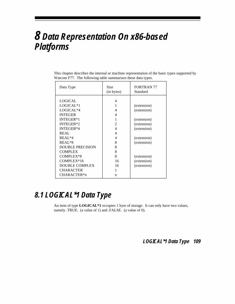
8 Data Representation On x86-basedPlatforms
This chapter describes the internal or machine representation of the basic types supported byWatcom F77. The following table summarizes these data types.
Data Type Size FORTRAN 77(in bytes) Standard
LOGICAL 4LOGICAL*1 1 (extension)LOGICAL*4 4 (extension)INTEGER 4INTEGER*1 1 (extension)INTEGER*2 2 (extension)INTEGER*4 4 (extension)REAL 4REAL*4 4 (extension)REAL*8 8 (extension)DOUBLE PRECISION 8COMPLEX 8COMPLEX*8 8 (extension)COMPLEX*16 16 (extension)DOUBLE COMPLEX 16 (extension)CHARACTER 1CHARACTER*n n
8.1 LOGICAL*1 Data TypeAn item of type LOGICAL*1 occupies 1 byte of storage. It can only have two values,namely .TRUE. (a value of 1) and .FALSE. (a value of 0).
LOGICAL*1 Data Type 109

Watcom FORTRAN 77 User’s Guide
8.2 LOGICAL and LOGICAL*4 Data TypesAn item of type LOGICAL or LOGICAL*4 occupies 4 bytes of storage. It can only havetwo values, namely .TRUE. (a value of 1) and .FALSE. (a value of 0).
8.3 INTEGER*1 Data TypeAn item of type INTEGER*1 occupies 1 byte of storage. Its value is in the following range.An integer n can be represented in 1 byte if
-128 <= n <= 127
8.4 INTEGER*2 Data TypeAn item of type INTEGER*2 occupies 2 bytes of storage. An integer n can be represented in2 bytes if
-32768 <= n <= 32767
8.5 INTEGER and INTEGER*4 Data TypesAn item of type INTEGER or INTEGER*4 occupies 4 bytes of storage (one numeric storageunit). An integer n can be represented in 4 bytes if
-2147483648 <= n <= 2147483647
8.6 REAL and REAL*4 Data TypesAn item of type REAL or REAL*4 is an approximate representation of a real number andoccupies 4 bytes (one numeric storage unit). If m is the magnitude of a real number x, then xcan be approximated if
-126 128
2 <= m < 2
or in more approximate terms if
110 REAL and REAL*4 Data Types
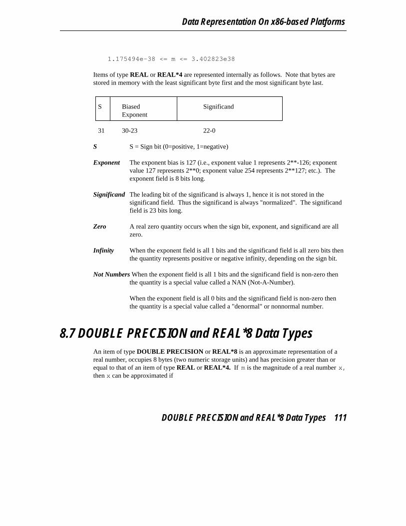
Data Representation On x86-based Platforms
1.175494e-38 <= m <= 3.402823e38
Items of type REAL or REAL*4 are represented internally as follows. Note that bytes arestored in memory with the least significant byte first and the most significant byte last.
S Biased SignificandExponent
31 30-23 22-0
S S = Sign bit (0=positive, 1=negative)
Exponent The exponent bias is 127 (i.e., exponent value 1 represents 2**-126; exponentvalue 127 represents 2**0; exponent value 254 represents 2**127; etc.). Theexponent field is 8 bits long.
Significand The leading bit of the significand is always 1, hence it is not stored in thesignificand field. Thus the significand is always "normalized". The significandfield is 23 bits long.
Zero A real zero quantity occurs when the sign bit, exponent, and significand are allzero.
Infinity When the exponent field is all 1 bits and the significand field is all zero bits thenthe quantity represents positive or negative infinity, depending on the sign bit.
Not Numbers When the exponent field is all 1 bits and the significand field is non-zero thenthe quantity is a special value called a NAN (Not-A-Number).
When the exponent field is all 0 bits and the significand field is non-zero thenthe quantity is a special value called a "denormal" or nonnormal number.
8.7 DOUBLE PRECISION and REAL*8 Data TypesAn item of type DOUBLE PRECISION or REAL*8 is an approximate representation of areal number, occupies 8 bytes (two numeric storage units) and has precision greater than orequal to that of an item of type REAL or REAL*4. If m is the magnitude of a real number x,then x can be approximated if
DOUBLE PRECISION and REAL*8 Data Types 111

Watcom FORTRAN 77 User’s Guide
-1022 1024
2 <= m < 2
or in more approximate terms if 2.2250738585072e-308 <= m <= 1.79769313486232e308
Items of type DOUBLE PRECISION or REAL*8 are represented internally as follows.Note that bytes are stored in memory with the least significant byte first and the mostsignificant byte last.
S Biased SignificandExponent
63 62-52 51-0
S S = Sign bit (0=positive, 1=negative)
Exponent The exponent bias is 1023 (i.e., exponent value 1 represents 2**-1022; exponentvalue 1023 represents 2**0; exponent value 2046 represents 2**1023; etc.).The exponent field is 11 bits long.
Significand The leading bit of the significand is always 1, hence it is not stored in thesignificand field. Thus the significand is always "normalized". The significandfield is 52 bits long.
Zero A double precision zero quantity occurs when the sign bit, exponent, andsignificand are all zero.
Infinity When the exponent field is all 1 bits and the significand field is all zero bits thenthe quantity represents positive or negative infinity, depending on the sign bit.
Not Numbers When the exponent field is all 1 bits and the significand field is non-zero thenthe quantity is a special value called a NAN (Not-A-Number).
When the exponent field is all 0 bits and the significand field is non-zero thenthe quantity is a special value called a "denormal" or nonnormal number.
112 DOUBLE PRECISION and REAL*8 Data Types
Data Representation On x86-based Platforms
8.8 COMPLEX, COMPLEX*8, and DOUBLE COMPLEXData Types
An item of type COMPLEX or COMPLEX*8 is an approximate representation of a complexnumber. The representation is an ordered pair of real numbers, the first representing the realpart of the complex number and the second representing the imaginary part of the complexnumber. Each item of type COMPLEX or COMPLEX*8 occupies 8 bytes (two consecutivenumeric storage units), the first being the real part and the second the imaginary part. Theapproximation of the real and imaginary parts of a complex number is the same degree ofapproximation used for items of type REAL.
8.9 COMPLEX*16 Data TypeAn item of type COMPLEX*16 is an approximate representation of a complex number. Therepresentation is an ordered pair of real numbers, the first representing the real part of thecomplex number and the second representing the imaginary part of the complex number.Each item of type COMPLEX*16 occupies 16 bytes (four consecutive numeric storageunits), the first two being the real part and the last two the imaginary part. The approximationof the real and imaginary parts of a complex number is the same degree of approximation usedfor items of type DOUBLE PRECISION.
8.10 CHARACTER Data TypeAn item of type CHARACTER represents a sequence of characters. Each character occupies1 byte of storage (1 character storage unit). The length of an item of type CHARACTER isthe number of characters it contains. Each character is assigned an integer that represents itsposition. Characters are numbered from 1 to n starting from the left, n being the number ofcharacters.
Items of type CHARACTER are represented by a string descriptor. A string descriptor hasthe following format.
CHARACTER Data Type 113

Watcom FORTRAN 77 User’s Guide
Offset
0 pointer to data
4 length of data
The pointer to the actual data is a 32-bit offset in the default data segment. The length isrepresented as a 32-bit unsigned integer.
8.11 Storage Organization of Data TypesThe following illustrates the relative size of the data types in terms of bytes. LOGICAL isequivalent to LOGICAL*4, INTEGER is equivalent to INTEGER*4, DOUBLEPRECISION is equivalent to REAL*8, and COMPLEX is equivalent to COMPLEX*8. Ifthe "short" option is used, LOGICAL is equivalent to LOGICAL*1 and INTEGER isequivalent to INTEGER*2.
Offset 0 1 2 3 4 5 6 7 8 9 10 11 12 13 14 15
in bytes
LOGICAL*1
LOGICAL*4
INTEGER*1
INTEGER*2
INTEGER*4
REAL*4
REAL*8
COMPLEX*8 real imaginary
COMPLEX*16 real part imaginary part
114 Storage Organization of Data Types
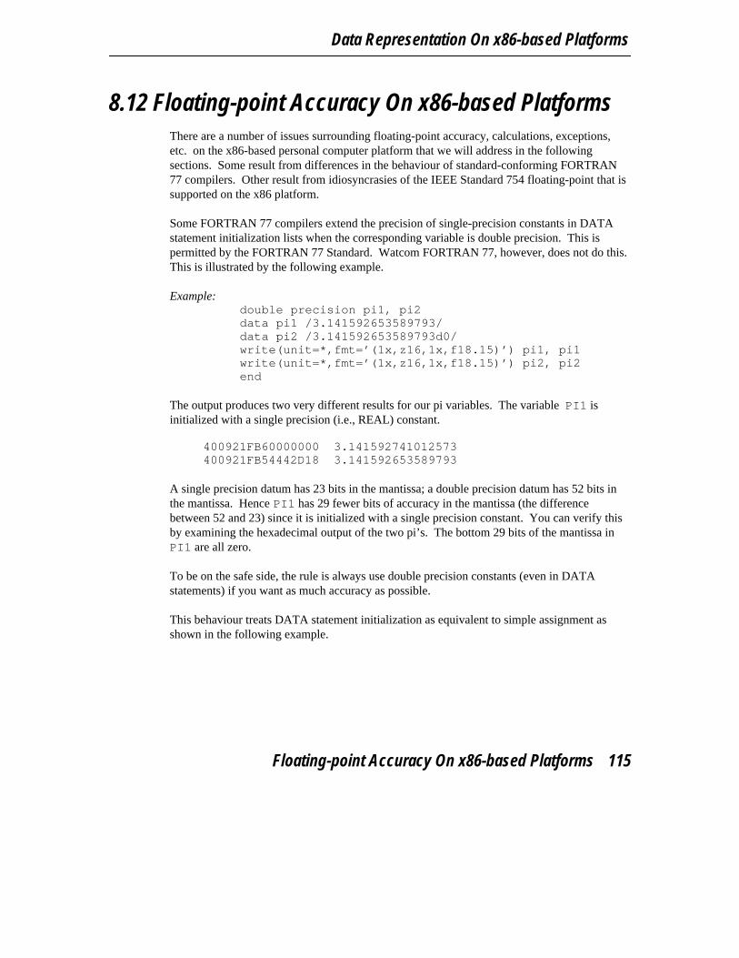
Data Representation On x86-based Platforms
8.12 Floating-point Accuracy On x86-based PlatformsThere are a number of issues surrounding floating-point accuracy, calculations, exceptions,etc. on the x86-based personal computer platform that we will address in the followingsections. Some result from differences in the behaviour of standard-conforming FORTRAN77 compilers. Other result from idiosyncrasies of the IEEE Standard 754 floating-point that issupported on the x86 platform.
Some FORTRAN 77 compilers extend the precision of single-precision constants in DATAstatement initialization lists when the corresponding variable is double precision. This ispermitted by the FORTRAN 77 Standard. Watcom FORTRAN 77, however, does not do this.This is illustrated by the following example.
Example:double precision pi1, pi2data pi1 /3.141592653589793/data pi2 /3.141592653589793d0/write(unit=*,fmt=’(1x,z16,1x,f18.15)’) pi1, pi1write(unit=*,fmt=’(1x,z16,1x,f18.15)’) pi2, pi2end
The output produces two very different results for our pi variables. The variable PI1 isinitialized with a single precision (i.e., REAL) constant.
400921FB60000000 3.141592741012573400921FB54442D18 3.141592653589793
A single precision datum has 23 bits in the mantissa; a double precision datum has 52 bits inthe mantissa. Hence PI1 has 29 fewer bits of accuracy in the mantissa (the differencebetween 52 and 23) since it is initialized with a single precision constant. You can verify thisby examining the hexadecimal output of the two pi’s. The bottom 29 bits of the mantissa inPI1 are all zero.
To be on the safe side, the rule is always use double precision constants (even in DATAstatements) if you want as much accuracy as possible.
This behaviour treats DATA statement initialization as equivalent to simple assignment asshown in the following example.
Floating-point Accuracy On x86-based Platforms 115

Watcom FORTRAN 77 User’s Guide
Example:double precision pi1, pi2pi1 = 3.141592653589793pi2 = 3.141592653589793d0write(unit=*,fmt=’(1x,z16,1x,f18.15)’) pi1, pi1write(unit=*,fmt=’(1x,z16,1x,f18.15)’) pi2, pi2end
The output follows: 400921FB60000000 3.141592741012573400921FB54442D18 3.141592653589793
A second consideration is illustrated by the next example. On some computer architectures,there is no difference in the exponent range between single and double precisionfloating-point representation. One such architecture is the IBM mainframe computer (e.g.,IBM System/370). When a double precision result is assigned to a single precision (REAL)variable, only precision in the mantissa is lost.
The x86 platform uses the IEEE Standard 754 floating-point representation. In thisrepresentation, the range of exponent values is greater in double precision than in singleprecision. As described in the section entitled "REAL and REAL*4 Data Types" on page 110,the range for single precision (REAL, REAL*4) numbers is:
1.175494e-38 <= m <= 3.402823e38
On the other hand, the range for double precision (DOUBLE PRECISION, REAL*8) numbersis:
2.2250738585072e-308 <= m <= 1.79769313486232e308
Double precision is described in the section entitled "DOUBLE PRECISION and REAL*8Data Types" on page 111. So you can see that a number like 1.0E234 can easily berepresented in double precision but not in single precision since the maximum positiveexponent value for single precision is 38.
8.13 Floating-point Exceptions On x86-basedPlatforms
The following types of exceptions can be enabled/disabled on PC’s with an 80x87floating-point unit (either a real FPU or a true emulator).
116 Floating-point Exceptions On x86-based Platforms
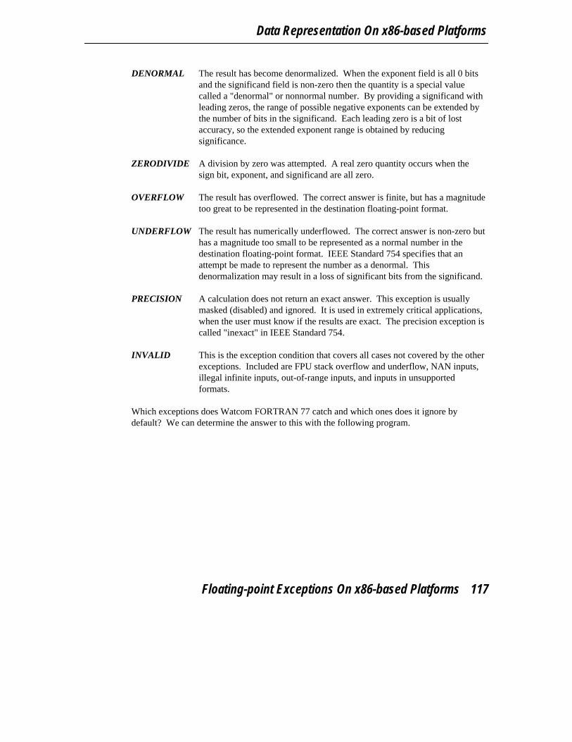
Data Representation On x86-based Platforms
DENORMAL The result has become denormalized. When the exponent field is all 0 bitsand the significand field is non-zero then the quantity is a special valuecalled a "denormal" or nonnormal number. By providing a significand withleading zeros, the range of possible negative exponents can be extended bythe number of bits in the significand. Each leading zero is a bit of lostaccuracy, so the extended exponent range is obtained by reducingsignificance.
ZERODIVIDE A division by zero was attempted. A real zero quantity occurs when thesign bit, exponent, and significand are all zero.
OVERFLOW The result has overflowed. The correct answer is finite, but has a magnitudetoo great to be represented in the destination floating-point format.
UNDERFLOW The result has numerically underflowed. The correct answer is non-zero buthas a magnitude too small to be represented as a normal number in thedestination floating-point format. IEEE Standard 754 specifies that anattempt be made to represent the number as a denormal. Thisdenormalization may result in a loss of significant bits from the significand.
PRECISION A calculation does not return an exact answer. This exception is usuallymasked (disabled) and ignored. It is used in extremely critical applications,when the user must know if the results are exact. The precision exception iscalled "inexact" in IEEE Standard 754.
INVALID This is the exception condition that covers all cases not covered by the otherexceptions. Included are FPU stack overflow and underflow, NAN inputs,illegal infinite inputs, out-of-range inputs, and inputs in unsupportedformats.
Which exceptions does Watcom FORTRAN 77 catch and which ones does it ignore bydefault? We can determine the answer to this with the following program.
Floating-point Exceptions On x86-based Platforms 117

Watcom FORTRAN 77 User’s Guide
* This program uses the C Library routine " control87"* to obtain the math coprocessor exception mask.
implicit noneinclude ’fsignal.fi’
character*8 statusinteger fp cw, bits
fp cw = control87( 0, 0 )bits = IAND( fp cw, MCW EM )print ’(a,1x,z4)’, ’Interrupt exception mask’, bitsprint *,’Invalid operation exception ’, status(bits, EM INVALID)print *,’Denormalized exception ’, status(bits, EM DENORMAL)print *,’Divide by 0 exception ’, status(bits, EM ZERODIVIDE)print *,’Overflow exception ’, status(bits, EM OVERFLOW)print *,’Underflow exception ’, status(bits, EM UNDERFLOW)print *,’Precision exception ’, status(bits, EM PRECISION)end
character*8 function status( bits, mask )integer bits, mask
if( IAND(bits,mask) .eq. 0 ) thenstatus = ’enabled’
elsestatus = ’disabled’
endifend
If you compile and run this program, the following output is produced. Interrupt exception mask 0032Invalid operation exception enabledDenormalized exception disabledDivide by 0 exception enabledOverflow exception enabledUnderflow exception disabledPrecision exception disabled
So, by default, the Watcom FORTRAN 77 run-time system will catch "invalid operation","divide by 0", and "overflow" exceptions. It ignores "denormal", "underflow", and"precision" exceptions. Thus calculations that produce very small results trend towards zero.Also, calculations that produce inexact results (a very common occurrence in floating-pointcalculations) are allowed to continue.
Suppose that you were interested in flagging calculations that result in denormalized orunderflowed results. To do this, we need to enable both DENORMAL and UNDERFLOWexceptions. This following program illustrates how to do this.
118 Floating-point Exceptions On x86-based Platforms

Data Representation On x86-based Platforms
*$ifdef 386*$ifdef stack conventions*$pragma aux clear87 "!"*$else*$pragma aux clear87 "! "*$endif*$else*$pragma aux clear87 "! "*$endif
implicit noneinclude ’fsignal.fi’
character*8 statusinteger fp cw, fp mask, bits
* get rid of any errors so we don’t cause an instant exceptioncall clear87
* fp mask determines the bits to enable and/or disablefp mask = 0
1 + EM DENORMAL2 + EM UNDERFLOW
* fp cw determines whether to enable(0) or disable(1)* (in this case, nothing is disabled)
fp cw = ’0000’x
fp cw = control87( fp cw, fp mask )
bits = IAND( fp cw, MCW EM )print ’(a,1x,z4)’, ’Interrupt exception mask’, bitsprint *,’Invalid operation exception ’, status(bits, EM INVALID)print *,’Denormalized exception ’, status(bits, EM DENORMAL)print *,’Divide by 0 exception ’, status(bits, EM ZERODIVIDE)print *,’Overflow exception ’, status(bits, EM OVERFLOW)print *,’Underflow exception ’, status(bits, EM UNDERFLOW)print *,’Precision exception ’, status(bits, EM PRECISION)end
character*8 function status( bits, mask )integer bits, mask
if( IAND(bits,mask) .eq. 0 ) thenstatus = ’enabled’
elsestatus = ’disabled’
endifend
If you compile and run this program, the following output is produced.
Floating-point Exceptions On x86-based Platforms 119

Watcom FORTRAN 77 User’s Guide
Interrupt exception mask 0020Invalid operation exception enabledDenormalized exception enabledDivide by 0 exception enabledOverflow exception enabledUnderflow exception enabledPrecision exception disabled
8.14 Compiler Options Relating to Floating-pointLet us take the program that we developed in the previous section and test it out. If youintroduce the variable FLT to the program and calculate the expression "2e-38 x 2e-38", youwould expect to see 0.0 printed when underflow exceptions are disabled and a run-timediagnostic when underflow exceptions are enabled. The statements that you would add areshow in the following.
real flt
flt=2e-38print *, flt*flt
* code to enable exceptions goes here
print *, flt*flt
end
If you compile the modified program with default options and run it, the result is as follows.
0.0000000Interrupt exception mask 0020Invalid operation exception enabledDenormalized exception enabledDivide by 0 exception enabledOverflow exception enabledUnderflow exception enabledPrecision exception disabled
0.0000000
This is not what we expected. Evaluation of the second expression did not produce therun-time diagnostic that we expected. The reason this happened is related to the compiler’sprocessing of the source code. By default, the compiler optimized the generated code byevaluating the expression "2e-38 x 2e-38" at compile time producing 0.0 as the result (due tothe underflow).
120 Compiler Options Relating to Floating-point

Data Representation On x86-based Platforms
flt=2e-38print *, flt*flt
reduces to
print *, 2e-28*2e-38
which further reduces to
print *, 0.0
Recompile the program using the "OP" option and run it. The result is as follows.
0.0000000Interrupt exception mask 0020Invalid operation exception enabledDenormalized exception enabledDivide by 0 exception enabledOverflow exception enabledUnderflow exception enabledPrecision exception disabled*ERR* KO-03 floating-point underflow
The use of the "OP" option will force the result to be stored in memory after each FORTRANstatement is executed. Thus, the source code is not optimized across statements.Compile-time versus run-time evaluation of expressions can lead to different results. It isvery instructive to compile and then run your application with a variety of compile-timeoptions to see the effect of optimizations. See the chapter entitled "Watcom FORTRAN 77Compiler Options" on page 5 for more information on compiler options.
Before we end this section, there is another important aspect of floating-point exceptions toconsider. A floating-point exception is triggered upon the execution of the next FPUinstruction following the one that caused the exception.
implicit none
real*4 areal*8 b
b=12.0d123a=b*bb=1.0a=b/2.0print *, a, bend
Compile this program with the "OP" and "DEBUG" options and then run it. The result isdisplayed next.
Compiler Options Relating to Floating-point 121
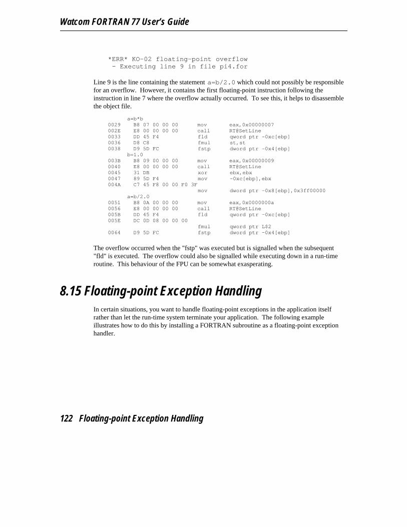
Watcom FORTRAN 77 User’s Guide
*ERR* KO-02 floating-point overflow- Executing line 9 in file pi4.for
Line 9 is the line containing the statement a=b/2.0 which could not possibly be responsiblefor an overflow. However, it contains the first floating-point instruction following theinstruction in line 7 where the overflow actually occurred. To see this, it helps to disassemblethe object file.
a=b*b
0029 B8 07 00 00 00 mov eax,0x00000007002E E8 00 00 00 00 call RT@SetLine0033 DD 45 F4 fld qword ptr -0xc[ebp]0036 D8 C8 fmul st,st0038 D9 5D FC fstp dword ptr -0x4[ebp]
b=1.0003B B8 09 00 00 00 mov eax,0x000000090040 E8 00 00 00 00 call RT@SetLine0045 31 DB xor ebx,ebx0047 89 5D F4 mov -0xc[ebp],ebx004A C7 45 F8 00 00 F0 3F
mov dword ptr -0x8[ebp],0x3ff00000a=b/2.0
0051 B8 0A 00 00 00 mov eax,0x0000000a0056 E8 00 00 00 00 call RT@SetLine005B DD 45 F4 fld qword ptr -0xc[ebp]005E DC 0D 08 00 00 00
fmul qword ptr L$20064 D9 5D FC fstp dword ptr -0x4[ebp]
The overflow occurred when the "fstp" was executed but is signalled when the subsequent"fld" is executed. The overflow could also be signalled while executing down in a run-timeroutine. This behaviour of the FPU can be somewhat exasperating.
8.15 Floating-point Exception HandlingIn certain situations, you want to handle floating-point exceptions in the application itselfrather than let the run-time system terminate your application. The following exampleillustrates how to do this by installing a FORTRAN subroutine as a floating-point exceptionhandler.
122 Floating-point Exception Handling
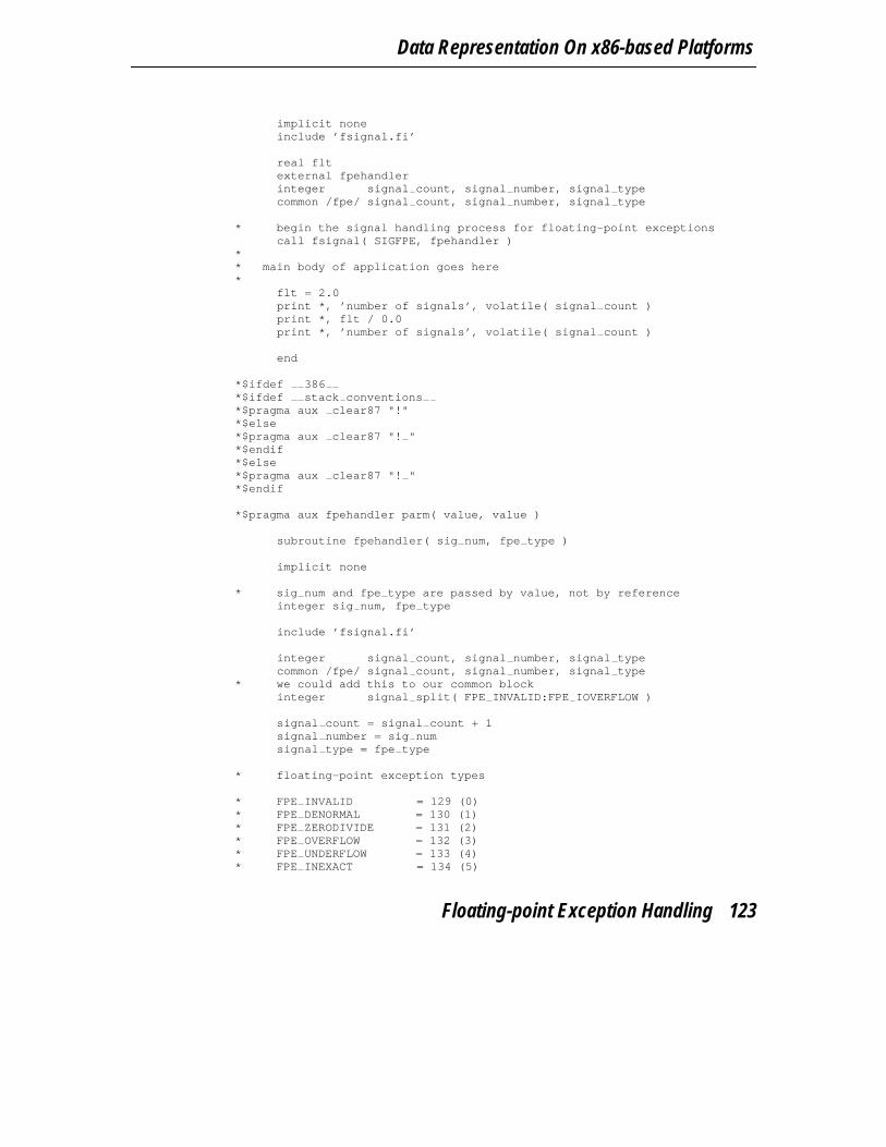
Data Representation On x86-based Platforms
implicit noneinclude ’fsignal.fi’
real fltexternal fpehandlerinteger signal count, signal number, signal typecommon /fpe/ signal count, signal number, signal type
* begin the signal handling process for floating-point exceptionscall fsignal( SIGFPE, fpehandler )
** main body of application goes here*
flt = 2.0print *, ’number of signals’, volatile( signal count )print *, flt / 0.0print *, ’number of signals’, volatile( signal count )
end
*$ifdef 386*$ifdef stack conventions*$pragma aux clear87 "!"*$else*$pragma aux clear87 "! "*$endif*$else*$pragma aux clear87 "! "*$endif
*$pragma aux fpehandler parm( value, value )
subroutine fpehandler( sig num, fpe type )
implicit none
* sig num and fpe type are passed by value, not by referenceinteger sig num, fpe type
include ’fsignal.fi’
integer signal count, signal number, signal typecommon /fpe/ signal count, signal number, signal type
* we could add this to our common blockinteger signal split( FPE INVALID:FPE IOVERFLOW )
signal count = signal count + 1signal number = sig numsignal type = fpe type
* floating-point exception types
* FPE INVALID = 129 (0)* FPE DENORMAL = 130 (1)* FPE ZERODIVIDE = 131 (2)* FPE OVERFLOW = 132 (3)* FPE UNDERFLOW = 133 (4)* FPE INEXACT = 134 (5)
Floating-point Exception Handling 123
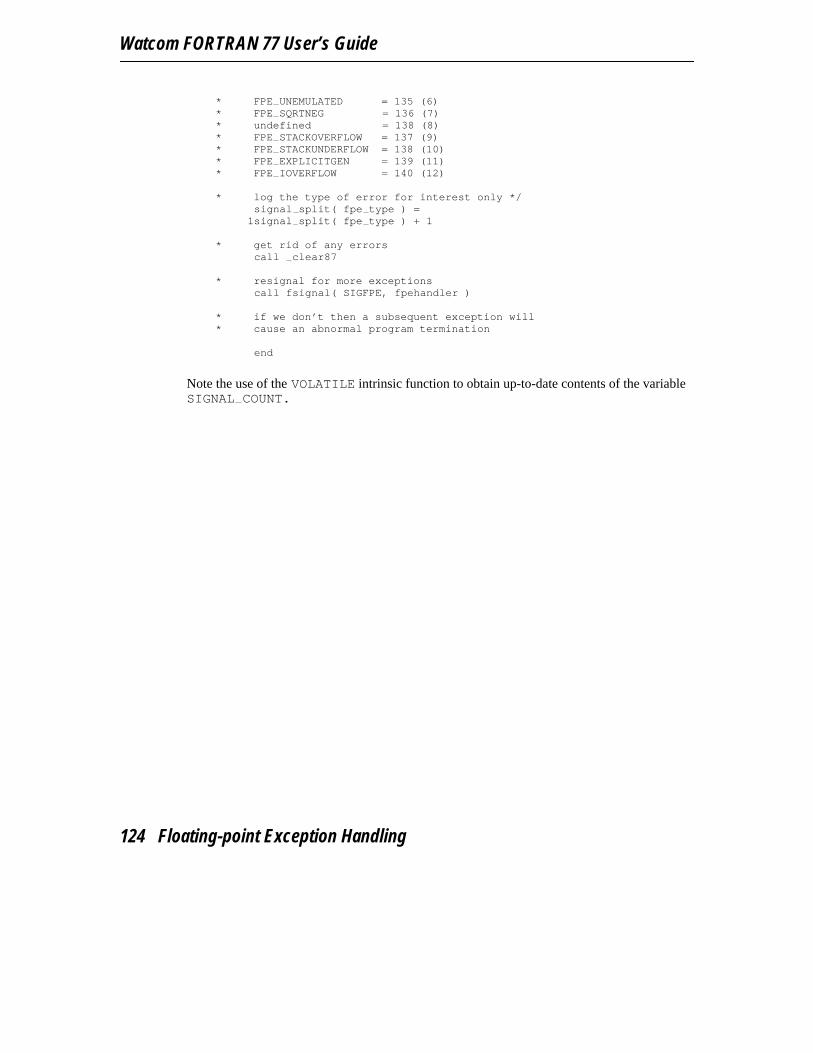
Watcom FORTRAN 77 User’s Guide
* FPE UNEMULATED = 135 (6)* FPE SQRTNEG = 136 (7)* undefined = 138 (8)* FPE STACKOVERFLOW = 137 (9)* FPE STACKUNDERFLOW = 138 (10)* FPE EXPLICITGEN = 139 (11)* FPE IOVERFLOW = 140 (12)
* log the type of error for interest only */signal split( fpe type ) =
1signal split( fpe type ) + 1
* get rid of any errorscall clear87
* resignal for more exceptionscall fsignal( SIGFPE, fpehandler )
* if we don’t then a subsequent exception will* cause an abnormal program termination
end
Note the use of the VOLATILE intrinsic function to obtain up-to-date contents of the variableSIGNAL COUNT.
124 Floating-point Exception Handling

16-bit Topics

16-bit Topics
126

9 16-bit Memory Models
9.1 IntroductionThis chapter describes the various 16-bit memory models supported by Watcom F77. Eachmemory model is distinguished by two properties; the code model used to implementsubprogram calls and the data model used to reference data.
9.2 16-bit Code ModelsThere are two code models;
1. the small code model and2. the big code model.
A small code model is one in which all calls to subprograms are made with near calls. In anear call, the destination address is 16 bits and is relative to the segment value in segmentregister CS. Hence, in a small code model, all code comprising your program, includinglibrary subprograms, must be less than 64K. Watcom F77 does not support the small codemodel.
A big code model is one in which all calls to subprograms are made with far calls. In a farcall, the destination address is 32 bits (a segment value and an offset relative to the segmentvalue). This model allows the size of the code comprising your program to exceed 64K.
9.3 16-bit Data ModelsThere are three data models;
1. the small data model,2. the big data model and3. the huge data model.
16-bit Data Models 127
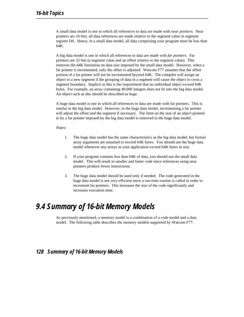
16-bit Topics
A small data model is one in which all references to data are made with near pointers. Nearpointers are 16 bits; all data references are made relative to the segment value in segmentregister DS. Hence, in a small data model, all data comprising your program must be less than64K.
A big data model is one in which all references to data are made with far pointers. Farpointers are 32 bits (a segment value and an offset relative to the segment value). Thisremoves the 64K limitation on data size imposed by the small data model. However, when afar pointer is incremented, only the offset is adjusted. Watcom F77 assumes that the offsetportion of a far pointer will not be incremented beyond 64K. The compiler will assign anobject to a new segment if the grouping of data in a segment will cause the object to cross asegment boundary. Implicit in this is the requirement that no individual object exceed 64Kbytes. For example, an array containing 40,000 integers does not fit into the big data model.An object such as this should be described as huge.
A huge data model is one in which all references to data are made with far pointers. This issimilar to the big data model. However, in the huge data model, incrementing a far pointerwill adjust the offset and the segment if necessary. The limit on the size of an object pointedto by a far pointer imposed by the big data model is removed in the huge data model.
Notes:
1. The huge data model has the same characteristics as the big data model, but formalarray arguments are assumed to exceed 64K bytes. You should use the huge datamodel whenever any arrays in your application exceed 64K bytes in size.
2. If your program contains less than 64K of data, you should use the small datamodel. This will result in smaller and faster code since references using nearpointers produce fewer instructions.
3. The huge data model should be used only if needed. The code generated in thehuge data model is not very efficient since a run-time routine is called in order toincrement far pointers. This increases the size of the code significantly andincreases execution time.
9.4 Summary of 16-bit Memory ModelsAs previously mentioned, a memory model is a combination of a code model and a datamodel. The following table describes the memory models supported by Watcom F77.
128 Summary of 16-bit Memory Models
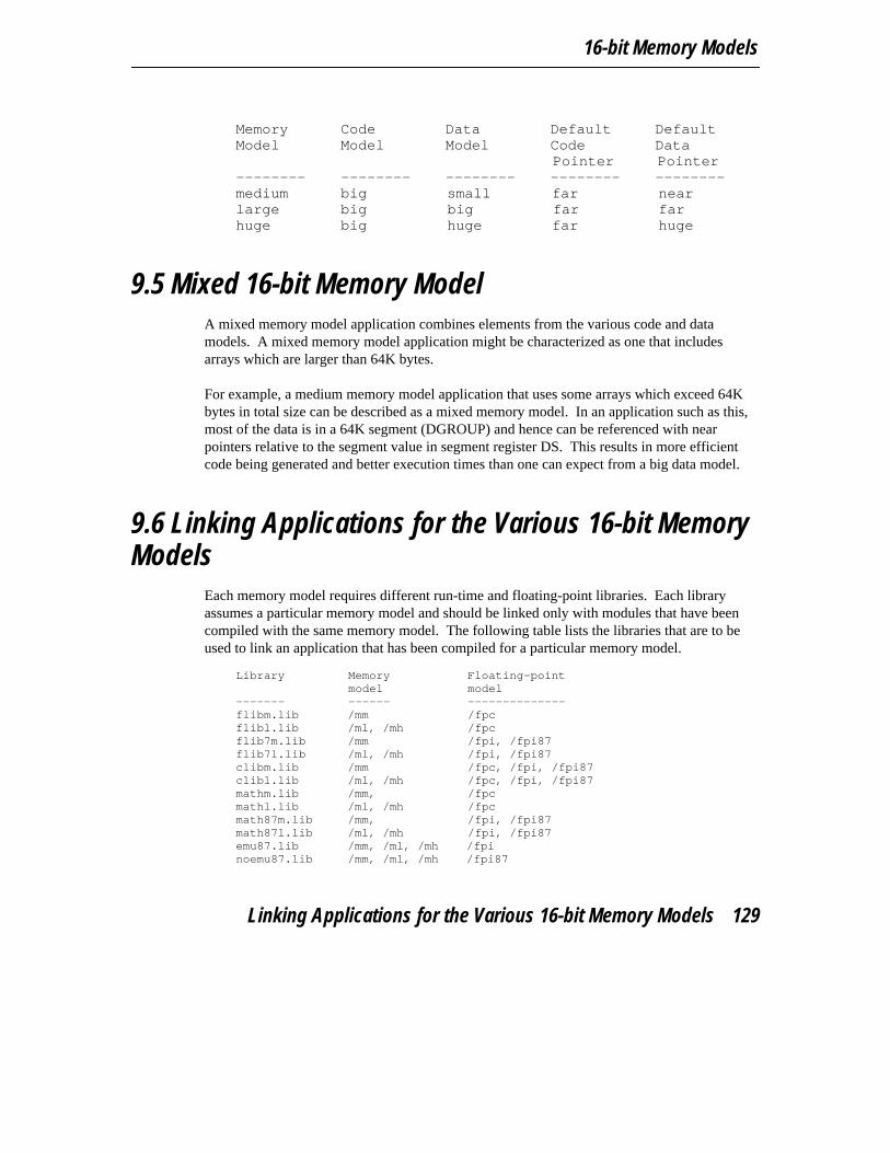
16-bit Memory Models
Memory Code Data Default DefaultModel Model Model Code Data
Pointer Pointer-------- -------- -------- -------- --------medium big small far nearlarge big big far farhuge big huge far huge
9.5 Mixed 16-bit Memory ModelA mixed memory model application combines elements from the various code and datamodels. A mixed memory model application might be characterized as one that includesarrays which are larger than 64K bytes.
For example, a medium memory model application that uses some arrays which exceed 64Kbytes in total size can be described as a mixed memory model. In an application such as this,most of the data is in a 64K segment (DGROUP) and hence can be referenced with nearpointers relative to the segment value in segment register DS. This results in more efficientcode being generated and better execution times than one can expect from a big data model.
9.6 Linking Applications for the Various 16-bit MemoryModels
Each memory model requires different run-time and floating-point libraries. Each libraryassumes a particular memory model and should be linked only with modules that have beencompiled with the same memory model. The following table lists the libraries that are to beused to link an application that has been compiled for a particular memory model.
Library Memory Floating-point
model model------- ------ --------------flibm.lib /mm /fpcflibl.lib /ml, /mh /fpcflib7m.lib /mm /fpi, /fpi87flib7l.lib /ml, /mh /fpi, /fpi87clibm.lib /mm /fpc, /fpi, /fpi87clibl.lib /ml, /mh /fpc, /fpi, /fpi87mathm.lib /mm, /fpcmathl.lib /ml, /mh /fpcmath87m.lib /mm, /fpi, /fpi87math87l.lib /ml, /mh /fpi, /fpi87emu87.lib /mm, /ml, /mh /fpinoemu87.lib /mm, /ml, /mh /fpi87
Linking Applications for the Various 16-bit Memory Models 129
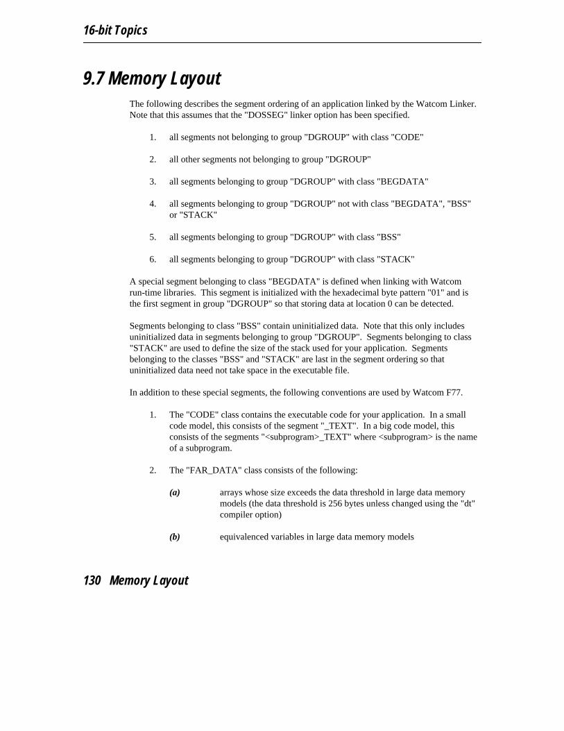
16-bit Topics
9.7 Memory LayoutThe following describes the segment ordering of an application linked by the Watcom Linker.Note that this assumes that the "DOSSEG" linker option has been specified.
1. all segments not belonging to group "DGROUP" with class "CODE"
2. all other segments not belonging to group "DGROUP"
3. all segments belonging to group "DGROUP" with class "BEGDATA"
4. all segments belonging to group "DGROUP" not with class "BEGDATA", "BSS"or "STACK"
5. all segments belonging to group "DGROUP" with class "BSS"
6. all segments belonging to group "DGROUP" with class "STACK"
A special segment belonging to class "BEGDATA" is defined when linking with Watcomrun-time libraries. This segment is initialized with the hexadecimal byte pattern "01" and isthe first segment in group "DGROUP" so that storing data at location 0 can be detected.
Segments belonging to class "BSS" contain uninitialized data. Note that this only includesuninitialized data in segments belonging to group "DGROUP". Segments belonging to class"STACK" are used to define the size of the stack used for your application. Segmentsbelonging to the classes "BSS" and "STACK" are last in the segment ordering so thatuninitialized data need not take space in the executable file.
In addition to these special segments, the following conventions are used by Watcom F77.
1. The "CODE" class contains the executable code for your application. In a smallcode model, this consists of the segment "_TEXT". In a big code model, thisconsists of the segments "<subprogram>_TEXT" where <subprogram> is the nameof a subprogram.
2. The "FAR_DATA" class consists of the following:
(a) arrays whose size exceeds the data threshold in large data memorymodels (the data threshold is 256 bytes unless changed using the "dt"compiler option)
(b) equivalenced variables in large data memory models
130 Memory Layout
10 16-bit Assembly LanguageConsiderations
10.1 IntroductionThis chapter will deal with the following topics.
1. The memory layout of a program compiled by Watcom F77.
2. The method for passing arguments and returning values.
3. The two methods for passing floating-point arguments and returning floating-pointvalues.
One method is used when one of the Watcom F77 "fpi", "fpi87" or "fpi387" optionsis specified for the generation of in-line 80x87 instructions. When the "fpi" optionis specified, an 80x87 emulator is included from a math library if the applicationincludes floating-point operations. When the "fpi87" or "fpi387" option is usedexclusively, the 80x87 emulator will not be included.
The other method is used when the Watcom F77 "fpc" option is specified. In thiscase, the compiler generates calls to floating-point support routines in the alternatemath libraries.
An understanding of the Intel 80x86 architecture is assumed.
10.2 Calling ConventionsThe following sections describe the method used by Watcom F77 to pass arguments.
The FORTRAN 77 language specifically requires that arguments be passed by reference.This means that instead of passing the value of an argument, its address is passed. This allowsa called subprogram to modify the value of the actual arguments. The following illustrates themethod used to pass arguments.
Calling Conventions 131
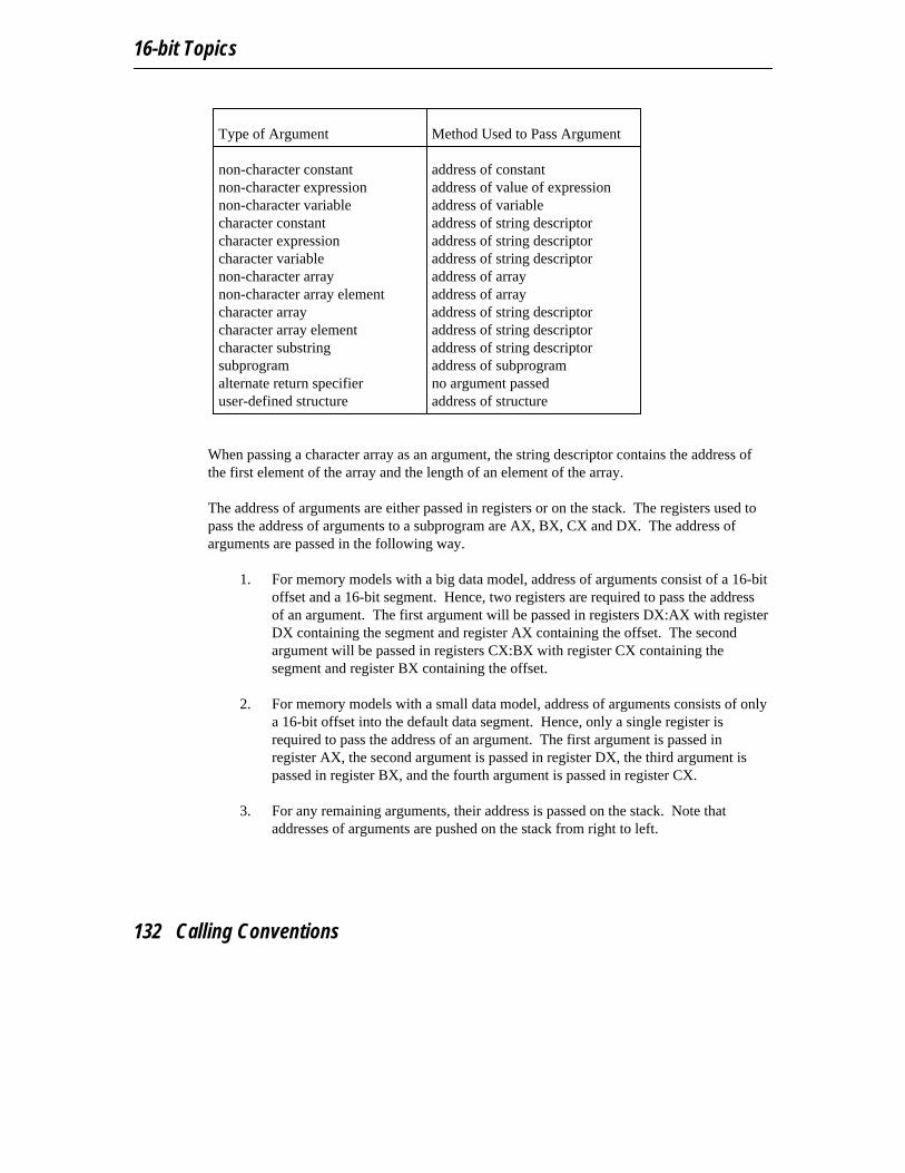
16-bit Topics
Type of Argument Method Used to Pass Argument
non-character constant address of constantnon-character expression address of value of expressionnon-character variable address of variablecharacter constant address of string descriptorcharacter expression address of string descriptorcharacter variable address of string descriptornon-character array address of arraynon-character array element address of arraycharacter array address of string descriptorcharacter array element address of string descriptorcharacter substring address of string descriptorsubprogram address of subprogramalternate return specifier no argument passeduser-defined structure address of structure
When passing a character array as an argument, the string descriptor contains the address ofthe first element of the array and the length of an element of the array.
The address of arguments are either passed in registers or on the stack. The registers used topass the address of arguments to a subprogram are AX, BX, CX and DX. The address ofarguments are passed in the following way.
1. For memory models with a big data model, address of arguments consist of a 16-bitoffset and a 16-bit segment. Hence, two registers are required to pass the addressof an argument. The first argument will be passed in registers DX:AX with registerDX containing the segment and register AX containing the offset. The secondargument will be passed in registers CX:BX with register CX containing thesegment and register BX containing the offset.
2. For memory models with a small data model, address of arguments consists of onlya 16-bit offset into the default data segment. Hence, only a single register isrequired to pass the address of an argument. The first argument is passed inregister AX, the second argument is passed in register DX, the third argument ispassed in register BX, and the fourth argument is passed in register CX.
3. For any remaining arguments, their address is passed on the stack. Note thataddresses of arguments are pushed on the stack from right to left.
132 Calling Conventions

16-bit Assembly Language Considerations
10.2.1 Processing Function Return Values with no 80x87
The way in which function values are returned is also dependent on the data type of thefunction. The following describes the method used to return function values.
1. LOGICAL*1 values are returned in register AL.
2. LOGICAL*4 values are returned in registers DX:AX.
3. INTEGER*1 values are returned in register AL.
4. INTEGER*2 values are returned in register AX.
5. INTEGER*4 values are returned in registers DX:AX.
6. REAL*4 values are returned in registers DX:AX.
7. REAL*8 values are returned in registers AX:BX:CX:DX.
8. For COMPLEX*8 functions, space is allocated on the stack by the caller for thereturn value. Register SI is set to point to the destination of the result. The calledfunction places the result at the location pointed to by register SI.
9. For COMPLEX*16 functions, space is allocated on the stack by the caller for thereturn value. Register SI is set to point to the destination of the result. The calledfunction places the result at the location pointed to by register SI.
10. For CHARACTER functions, an additional argument is passed. This argument isthe address of the string descriptor for the result. Note that the address of the stringdescriptor can be passed in any of the registers that are used to pass actualarguments.
11. For functions that return a user-defined structure, space is allocated on the stack bythe caller for the return value. Register SI is set to point to the destination of theresult. The called function places the result at the location pointed to by register SI.Note that a structure of size 1, 2 or 4 bytes is returned in register AL, AX orDX:AX respectively.
Calling Conventions 133
16-bit Topics
10.2.2 Processing Function Return Values Using an 80x87
The following describes the method used to return function values when your application iscompiled using the "fpi87" or "fpi" option.
1. For REAL*4 functions, the result is returned in floating-point register ST(0).2. For REAL*8 functions, the result is returned in floating-point register ST(0).3. All other function values are returned in the way described in the previous section.
10.2.3 Processing Alternate Returns
Alternate returns are processed by the caller and are only allowed in subroutines. The calledsubroutine places the value specified in the RETURN statement in register AX. Note that thevalue returned in register AX is ignored if there are no alternate return specifiers in the actualargument list.
10.2.4 Alternate Method of Passing Character Arguments
As previously described, character arguments are passed using string descriptors. Recall thata string descriptor contains a pointer to the actual character data and the length of thecharacter data. When passing character data, both a pointer and length are required by thesubprogram being called. When using a string descriptor, this information can be passedusing a single argument, namely the pointer to the string descriptor.
An alternate method of passing character arguments is also supported and is selected when the"nodescriptor" option is specified. In this method, the pointer to the character data and thelength of the character data are passed as two separate arguments. The character argumentlengths are appended to the end of the actual argument list.
Let us consider the following example. INTEGER A, CCHARACTER B, DCALL SUB( A, B, C, D )
In the above example, the first argument is of type INTEGER, the second argument is of typeCHARACTER, the third argument is of type INTEGER, and the fourth argument is of typeCHARACTER. If the character arguments were passed by descriptor, the argument list wouldresemble the following.
1. The first argument would be the address of A.2. The second argument would be the address of the string descriptor for B.
134 Calling Conventions
16-bit Assembly Language Considerations
3. The third argument would be the address of C.4. The fourth argument would be the address of the string descriptor for D.
If we specified the "nodescriptor" option, the argument list would be as follows.
1. The first argument would be the address of A.2. The second argument would be the address of the character data for B.3. The third argument would be the address of C.4. The fourth argument would be the address of the character data for D.5. A hidden argument for the length of B would be the fifth argument.6. A hidden argument for the length of D would be the sixth argument.
Note that the arguments corresponding to the length of the character arguments are passed asINTEGER*2 arguments.
10.2.4.1 Character Functions
By default, when a character function is called, a hidden argument is passed at the end of theactual argument list. This hidden argument is a pointer to the string descriptor used for thereturn value of the character function. When the alternate method of passing characterarguments is specified by using the "nodescriptor" option, the string descriptor for the returnvalue is passed to the function as two hidden arguments, similar to the way characterarguments were passed. However the two hidden arguments for the return value of thecharacter function are placed at the beginning of the actual argument list. The first argumentis the the pointer to the storage immediately followed by the size of the storage.
10.3 Memory LayoutThe following describes the segment ordering of an application linked by the Watcom Linker.Note that this assumes that the "DOSSEG" linker option has been specified.
1. all segments not belonging to group "DGROUP" with class "CODE"
2. all other segments not belonging to group "DGROUP"
3. all segments belonging to group "DGROUP" with class "BEGDATA"
4. all segments belonging to group "DGROUP" not with class "BEGDATA", "BSS"or "STACK"
5. all segments belonging to group "DGROUP" with class "BSS"
Memory Layout 135

16-bit Topics
6. all segments belonging to group "DGROUP" with class "STACK"
A special segment belonging to class "BEGDATA" is defined when linking with Watcomrun-time libraries. This segment is initialized with the hexadecimal byte pattern "01" and isthe first segment in group "DGROUP" so that storing data at location 0 can be detected.
Segments belonging to class "BSS" contain uninitialized data. Note that this only includesuninitialized data in segments belonging to group "DGROUP". Segments belonging to class"STACK" are used to define the size of the stack used for your application. Segmentsbelonging to the classes "BSS" and "STACK" are last in the segment ordering so thatuninitialized data need not take space in the executable file.
In addition to these special segments, the following conventions are used by Watcom F77.
1. The "CODE" class contains the executable code for your application. In a smallcode model, this consists of the segment "_TEXT". In a big code model, thisconsists of the segments "<subprogram>_TEXT" where <subprogram> is the nameof a subprogram.
2. The "FAR_DATA" class consists of the following:
(a) arrays whose size exceeds the data threshold in large data memorymodels (the data threshold is 256 bytes unless changed using the "dt"compiler option)
(b) equivalenced variables in large data memory models
10.4 Writing Assembly Language SubprogramsWhen writing assembly language subprograms, use the following guidelines.
1. All used registers must be saved on entry and restored on exit except those used topass arguments and return values. Note that segment registers only have to besaved and restored if you are compiling your application with the "sr" option.
2. The direction flag must be clear before returning to the caller.
3. In a small code model, any segment containing executable code must belong to thesegment "_TEXT" and the class "CODE". The segment "_TEXT" must have a"combine" type of "PUBLIC". On entry, register CS contains the segment addressof the segment "_TEXT". In a big code model there is no restriction on the namingof segments which contain executable code.
136 Writing Assembly Language Subprograms

16-bit Assembly Language Considerations
4. In a small data model, segment register DS contains the segment address of thedefault data segment (group "DGROUP"). In a big data model, segment registerSS (not DS) contains the segment address of the default data segment (group"DGROUP").
5. When writing assembly language subprograms for the small code model, you mustdeclare them as "near". If you wish to write assembly language subprograms forthe big code model, you must declare them as "far".
6. Use the ".8087" pseudo-op so that floating-point constants are in the correct format.
7. The called subprogram must remove arguments that were passed on the stack in the"ret" instruction.
8. In general, when naming segments for your code or data, you should follow theconventions described in the section entitled "Memory Layout" in this chapter.
Consider the following example.
INTEGER HRS, MINS, SECS, HSECSCALL GETTIM( HRS, MINS, SECS, HSECS )PRINT 100, HRS, MINS, SECS, HSECS
100 FORMAT( 1X,I2.2,’:’,I2.2,’:’,I2.2,’.’,I2.2 )END
GETTIM is an assembly language subroutine that gets the current time. It requires fourinteger arguments. The arguments are passed by reference so that the subroutine can returnthe hour, minute, seconds and hundredths of a second for the current time. These argumentswill be passed to GETTIM in the following way.
1. The address of the first argument will be passed in registers DX:AX.2. The address of the second argument will be passed in registers CX:BX.3. The address of the third argument will be passed on the stack.4. The address of the fourth argument will be passed on the stack.
The following is an assembly language subprogram which implements GETTIM.
Large Memory Model (big code, big data) GETTIM TEXT segment byte public ’CODE’
assume CS:GETTIM TEXT
Writing Assembly Language Subprograms 137

16-bit Topics
public GETTIMGETTIM proc far
push DI ; save register(s)push ES ; ...push DS ; ...push BP ; get addressability to argumentsmov BP,SP ; ...mov ES,DX ; ES:DI points to hoursmov DI,AX ; ...mov DS,CX ; DS:BX points to minutesmov AH,2ch ; set DOS "get time" functionint 21h ; issue DOS function callmov AL,CH ; get hourscbw ; ...mov ES:[DI],AX ; return hourssub AX,AX ; ...mov ES:2[DI],AX ; ...mov AL,CL ; get minutescbw ; ...mov [BX],AX ; return minutessub AX,AX ; ...mov 2[BX],AX ; ...mov DS,14[BP] ; get address of secondsmov DI,12[BP] ; ...mov AL,DH ; get secondscbw ; ...mov [DI],AX ; return secondssub AX,AX ; ...mov 2[DI],AX ; ...mov DS,18[BP] ; get address of ticksmov DI,16[BP] ; ...mov AL,DL ; get tickscbw ; ...cwd ; ...mov [DI],AX ; return ticksmov 2[DI],DX ; ...pop BP ; restore register(s)pop DS ; ...pop ES ; ...pop DI ; ...ret 8 ; return
GETTIM endpGETTIM TEXT ends
end
Notes:
1. Two arguments were passed on the stack so a "ret 8" instruction is used to return tothe caller.
2. Registers AX, BX, CX and DX were not saved and restored since they were used topass arguments. However, registers DS, ES, DI and BP were modified in thesubprogram and hence must be saved and restored.
138 Writing Assembly Language Subprograms
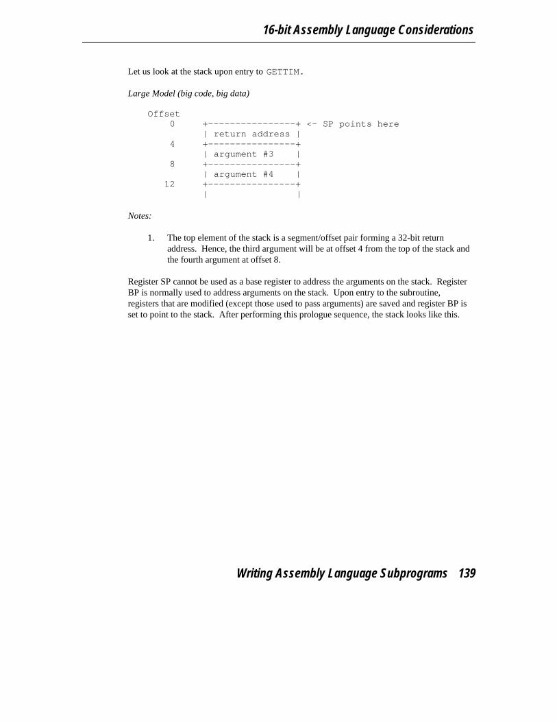
16-bit Assembly Language Considerations
Let us look at the stack upon entry to GETTIM.
Large Model (big code, big data) Offset
0 +----------------+ <- SP points here| return address |
4 +----------------+| argument #3 |
8 +----------------+| argument #4 |
12 +----------------+| |
Notes:
1. The top element of the stack is a segment/offset pair forming a 32-bit returnaddress. Hence, the third argument will be at offset 4 from the top of the stack andthe fourth argument at offset 8.
Register SP cannot be used as a base register to address the arguments on the stack. RegisterBP is normally used to address arguments on the stack. Upon entry to the subroutine,registers that are modified (except those used to pass arguments) are saved and register BP isset to point to the stack. After performing this prologue sequence, the stack looks like this.
Writing Assembly Language Subprograms 139

16-bit Topics
Large Model (big code, big data) Offset
0 +----------------+ <- BP and SP point here| saved BP |
2 +----------------+| saved DS |
4 +----------------+| saved ES |
6 +----------------+| saved DI |
8 +----------------+| return address |
12 +----------------+| argument #3 |
16 +----------------+| argument #4 |
20 +----------------+| |
As the above diagram shows, the third argument is at offset 12 from register BP and the fourthargument is at offset 16.
10.4.1 Returning Values from Assembly Language Functions
The following illustrates the way function values are to be returned from assembly languagefunctions.
1. A LOGICAL*1 function. L1 TEXT segment byte public ’CODE’
assume CS:L1 TEXTpublic L1
L1 proc farmov AL,1ret
L1 endpL1 TEXT ends
end
2. A LOGICAL*4 function. L4 TEXT segment byte public ’CODE’
assume CS:L4 TEXTpublic L4
L4 proc farmov AX,0
140 Writing Assembly Language Subprograms
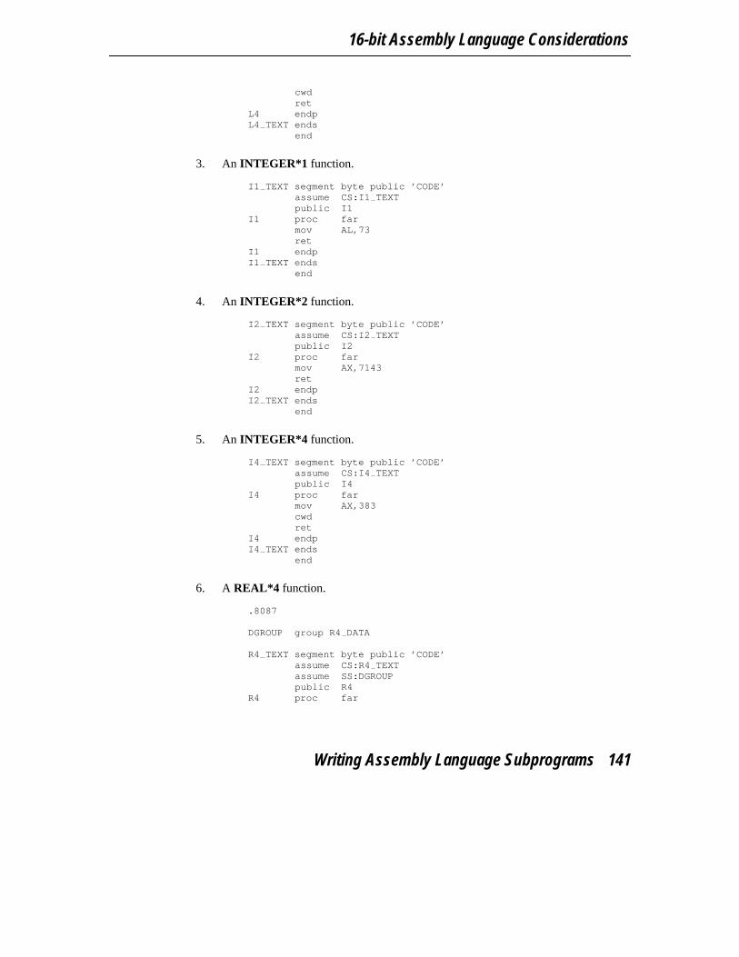
16-bit Assembly Language Considerations
cwdret
L4 endpL4 TEXT ends
end
3. An INTEGER*1 function. I1 TEXT segment byte public ’CODE’
assume CS:I1 TEXTpublic I1
I1 proc farmov AL,73ret
I1 endpI1 TEXT ends
end
4. An INTEGER*2 function. I2 TEXT segment byte public ’CODE’
assume CS:I2 TEXTpublic I2
I2 proc farmov AX,7143ret
I2 endpI2 TEXT ends
end
5. An INTEGER*4 function. I4 TEXT segment byte public ’CODE’
assume CS:I4 TEXTpublic I4
I4 proc farmov AX,383cwdret
I4 endpI4 TEXT ends
end
6. A REAL*4 function. .8087
DGROUP group R4 DATA
R4 TEXT segment byte public ’CODE’assume CS:R4 TEXTassume SS:DGROUPpublic R4
R4 proc far
Writing Assembly Language Subprograms 141
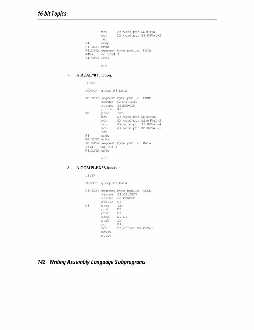
16-bit Topics
mov AX,word ptr SS:R4Valmov DX,word ptr SS:R4Val+2ret
R4 endpR4 TEXT endsR4 DATA segment byte public ’DATA’R4Val dd 1314.3R4 DATA ends
end
7. A REAL*8 function. .8087
DGROUP group R8 DATA
R8 TEXT segment byte public ’CODE’assume CS:R8 TEXTassume SS:DGROUPpublic R8
R8 proc farmov DX,word ptr SS:R8Valmov CX,word ptr SS:R8Val+2mov BX,word ptr SS:R8Val+4mov AX,word ptr SS:R8Val+6ret
R8 endpR8 TEXT endsR8 DATA segment byte public ’DATA’R8Val dq 103.3R8 DATA ends
end
8. A COMPLEX*8 function. .8087
DGROUP group C8 DATA
C8 TEXT segment byte public ’CODE’assume CS:C8 TEXTassume SS:DGROUPpublic C8
C8 proc farpush DIpush ESxchg DI,SIpush SSpop ESmov SI,offset SS:C8Valmovswmovsw
142 Writing Assembly Language Subprograms

16-bit Assembly Language Considerations
movswmovswpop ESpop DIret
C8 endpC8 TEXT ends
C8 DATA segment byte public ’DATA’C8Val dd 2.2
dd 2.2C8 DATA ends
end
9. A COMPLEX*16 function. .8087
DGROUP group C16 DATA
C16 TEXT segment byte public ’CODE’assume CS:C16 TEXTassume SS:DGROUPpublic C16
C16 proc farpush DIpush ESpush CXxchg DI,SIpush SSpop ESmov SI,offset SS:C16Valmov CX,8repe movswpop CXpop ESpop DIret
C16 endpC16 TEXT ends
C16 DATA segment byte public ’DATA’C16Val dq 3.3
dq 3.3C16 DATA ends
end
10. A CHARACTER function. CHR TEXT segment byte public ’CODE’
assume CS:CHR TEXTpublic CHR
CHR proc farpush DI
Writing Assembly Language Subprograms 143

16-bit Topics
push ESmov ES,DXmov DI,AXles DI,ES:[DI]mov byte ptr ES:[DI],’F’pop ESpop DIret
CHR endpCHR TEXT ends
end
11. A function returning a user-defined structure. DGROUP group STRUCT DATA
STRUCT TEXT segment byte public ’CODE’assume CS:STRUCT TEXTassume SS:DGROUPpublic C16
STRUCT proc farpush DIpush ESpush CXxchg DI,SIpush SSpop ESmov SI,offset SS:StructValmov CX,4repe movswpop CXpop ESpop DIret
STRUCT endpSTRUCT TEXT ends
STRUCT DATA segment byte public ’DATA’StructVal dd 7
dd 3STRUCT DATA ends
end
If you are using an 80x87 to return floating-point values, only assembly language functions oftype REAL*4 and REAL*8 need to be modified.
1. A REAL*4 function using an 80x87.
144 Writing Assembly Language Subprograms

16-bit Assembly Language Considerations
.8087
DGROUP group R4 DATA
R4 TEXT segment byte public ’CODE’assume CS:R4 TEXTassume SS:DGROUPpublic R4
R4 proc farfld dword ptr SS:R4Valret
R4 endpR4 TEXT endsR4 DATA segment byte public ’DATA’R4Val dd 1314.3R4 DATA ends
end
2. A REAL*8 function using an 80x87. .8087
DGROUP group R8 DATA
R8 TEXT segment byte public ’CODE’assume CS:R8 TEXTassume SS:DGROUPpublic R8
R8 proc farfld qword ptr SS:R8Valret
R8 endpR8 TEXT endsR8 DATA segment byte public ’DATA’R8Val dq 103.3R8 DATA ends
end
Notes:
1. The ".8087" pseudo-op must be specified so that all floating-point constants aregenerated in 8087 format.
2. When returning values on the stack, remember to use a segment override to thestack segment (SS).
The following is an example of a Watcom F77 program calling the above assembly languagesubprograms.
Writing Assembly Language Subprograms 145
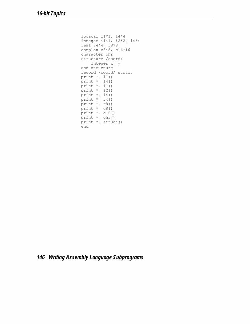
16-bit Topics
logical l1*1, l4*4integer i1*1, i2*2, i4*4real r4*4, r8*8complex c8*8, c16*16character chrstructure /coord/
integer x, yend structurerecord /coord/ structprint *, l1()print *, l4()print *, i1()print *, i2()print *, i4()print *, r4()print *, r8()print *, c8()print *, c16()print *, chr()print *, struct()end
146 Writing Assembly Language Subprograms

11 16-bit Pragmas
11.1 IntroductionA pragma is a compiler directive that provides the following capabilities.
• Pragmas can be used to direct the Watcom F77 code generator to emit specializedsequences of code for calling functions which use argument passing and value returntechniques that differ from the default used by Watcom F77.
• Pragmas can be used to describe attributes of functions (such as side effects) that arenot possible at the FORTRAN 77 language level. The code generator can use thisinformation to generate more efficient code.
• Any sequence of in-line machine language instructions, including DOS and BIOSfunction calls, can be generated in the object code.
Pragmas are specified in the source file using the pragma directive. The following notation isused to describe the syntax of pragmas.
keywords A keyword is shown in a mono-spaced courier font.
program-item A program-item is shown in a roman bold-italics font. A program-item is asymbol name or numeric value supplied by the programmer.
punctuation A punctuation character shown in a mono-spaced courier font must beentered as is.
A punctuation character shown in a roman bold-italics font is used to describesyntax. The following syntactical notation is used.
[abc] The item abc is optional.
{abc} The item abc may be repeated zero or more times.
a|b|c One of a, b or c may be specified.
Introduction 147
16-bit Topics
a ::= b The item a is defined in terms of b.
(a) Item a is evaluated first.
The following classes of pragmas are supported.
• pragmas that specify default libraries
• pragmas that provide auxiliary information used for code generation
11.2 Using Pragmas to Specify Default LibrariesDefault libraries are specified in special object module records. Library names are extractedfrom these special records by the Watcom Linker. When unresolved references remain afterprocessing all object modules specified in linker "FILE" directives, these default libraries aresearched after all libraries specified in linker "LIBRARY" directives have been searched.
By default, that is if no library pragma is specified, the Watcom F77 compiler generates, inthe object file defining the main program, default libraries corresponding to the memorymodel and floating-point model used to compile the file. For example, if you have compiledthe source file containing the main program for the medium memory model and thefloating-point calls floating-point model, the library "flibm" will be placed in the object file.
If you wish to add your own default libraries to this list, you can do so with a library pragma.Consider the following example.
*$pragma library mylib
The name "mylib" will be added to the list of default libraries specified in the object file.
If you wish to specify more than one library in a library pragma you must separate them withspaces as in the following example.
*$pragma library mylib \watcom\lib286\dos\graph.lib*$pragma library mylib \watcom\lib386\dos\graph.lib
If no libraries are specified as in the following example, *$pragma library
the run-time libraries corresponding to the memory and floating-point models used to compilethe file will be generated.
148 Using Pragmas to Specify Default Libraries

16-bit Pragmas
11.3 Auxiliary PragmasThe following sections describe the capabilities provided by auxiliary pragmas.
The backslash character (’\’) is used to continue a pragma on the next line. Text following thebackslash character is ignored. The line continuing the pragma must start with a commentcharacter (’c’, ’C’ or ’*’).
11.3.1 Specifying Symbol Attributes
Auxiliary pragmas are used to describe attributes that affect code generation. Initially, thecompiler defines a default set of attributes. Each auxiliary pragma refers to one of thefollowing.
1. a symbol (such as a variable or function)2. the default set of attributes defined by the compiler
When an auxiliary pragma refers to a particular symbol, a copy of the current set of defaultattributes is made and merged with the attributes specified in the auxiliary pragma. Theresulting attributes are assigned to the specified symbol and can only be changed by anotherauxiliary pragma that refers to the same symbol.
When "default" is specified instead of a symbol name, the attributes specified by the auxiliarypragma change the default set of attributes. The resulting attributes are used by all symbolsthat have not been specifically referenced by a previous auxiliary pragma.
Note that all auxiliary pragmas are processed before code generation begins. Consider thefollowing example.
code in which symbol x is referenced*$pragma aux y <attrs 1>code in which symbol y is referencedcode in which symbol z is referenced*$pragma aux default <attrs 2>*$pragma aux x <attrs 3>
Auxiliary attributes are assigned to x, y and z in the following way.
1. Symbol x is assigned the initial default attributes merged with the attributesspecified by <attrs 2> and <attrs 3>.
Auxiliary Pragmas 149

16-bit Topics
2. Symbol y is assigned the initial default attributes merged with the attributesspecified by <attrs 1>.
3. Symbol z is assigned the initial default attributes merged with the attributesspecified by <attrs 2>.
11.3.2 Alias Names
When a symbol referred to by an auxiliary pragma includes an alias name, the attributes of thealias name are also assumed by the specified symbol.
There are two methods of specifying alias information. In the first method, the symbolassumes only the attributes of the alias name; no additional attributes can be specified. Thesecond method is more general since it is possible to specify an alias name as well asadditional auxiliary information. In this case, the symbol assumes the attributes of the aliasname as well as the attributes specified by the additional auxiliary information.
The simple form of the auxiliary pragma used to specify an alias is as follows.
*$pragma aux ( sym, alias )
where description:
sym is any valid FORTRAN 77 identifier.
alias is the alias name and is any valid FORTRAN 77 identifier.
Consider the following example. *$pragma aux value args parm (value) *$pragma aux ( rtn, value args )
The routine rtn assumes the attributes of the alias name push args which specifies thatthe arguments to rtn are passed by value.
The general form of an auxiliary pragma that can be used to specify an alias is as follows.
150 Auxiliary Pragmas

16-bit Pragmas
*$pragma aux ( alias ) sym aux_attrs
where description:
alias is the alias name and is any valid FORTRAN 77 identifier.
sym is any valid FORTRAN 77 identifier.
aux_attrs are attributes that can be specified with the auxiliary pragma.
Consider the following example. *$pragma aux WC "* " parm (value)*$pragma aux (WC) rtn1*$pragma aux (WC) rtn2*$pragma aux (WC) rtn3
The routines rtn1, rtn2 and rtn3 assume the same attributes as the alias name WC whichdefines the calling convention used by the Watcom C compiler. Whenever calls are made tortn1, rtn2 and rtn3, the Watcom C calling convention will be used. Note thatarguments must be passed by value. By default, Watcom F77 passes arguments by reference.
Note that if the attributes of WC change, only one pragma needs to be changed. If we had notused an alias name and specified the attributes in each of the three pragmas for rtn1, rtn2and rtn3, we would have to change all three pragmas. This approach also reduces theamount of memory required by the compiler to process the source file.
WARNING! The alias name WC is just another symbol. If WC appeared in your sourcecode, it would assume the attributes specified in the pragma for WC.
11.3.3 Predefined Aliases
A number of symbols are predefined by the compiler with a set of attributes that describe aparticular calling convention. These symbols can be used as aliases. The following is a list ofthese symbols.
Auxiliary Pragmas 151

16-bit Topics
__cdecl cdecl defines the calling convention used by Microsoft compilers.
__pascal pascal defines the calling convention used by OS/2 1.x and Windows 3.xAPI functions.
The following describes the attributes of the above alias names.
11.3.3.1 Predefined "__cdecl" Alias *$pragma aux cdecl " *" \c parm caller [] \c value struct float struct routine [ax] \c modify [ax bx cx dx es]
Notes:
1. All symbols are preceded by an underscore character.
2. Arguments are pushed on the stack from right to left. That is, the last argument ispushed first. The calling routine will remove the arguments from the stack.
3. Floating-point values are returned in the same way as structures. When a structureis returned, the called routine allocates space for the return value and returns apointer to the return value in register AX.
4. Registers AX, BX, CX and DX, and segment register ES are not saved and restoredwhen a call is made.
11.3.3.2 Predefined "__pascal" Alias *$pragma aux pascal "^" \c parm reverse routine [] \c value struct float struct caller [] \c modify [ax bx cx dx es]
Notes:
1. All symbols are mapped to upper case.
2. Arguments are pushed on the stack in reverse order. That is, the first argument ispushed first, the second argument is pushed next, and so on. The routine beingcalled will remove the arguments from the stack.
152 Auxiliary Pragmas

16-bit Pragmas
3. Floating-point values are returned in the same way as structures. When a structureis returned, the caller allocates space on the stack. The address of the allocatedspace will be pushed on the stack immediately before the call instruction. Uponreturning from the call, register AX will contain address of the space allocated forthe return value.
4. Registers AX, BX, CX and DX, and segment register ES are not saved and restoredwhen a call is made.
11.3.4 Alternate Names for Symbols
The following form of the auxiliary pragma can be used to describe the mapping of a symbolfrom its source form to its object form.
*$pragma aux sym obj_name
where description:
sym is any valid FORTRAN 77 identifier.
obj_name is any character string enclosed in double quotes.
When specifying obj name, the asterisk character (’*’) has a special meaning; it is aplaceholder for the upper case version of sym.
In the following example, the name "myrtn" will be replaced by "MYRTN_" in the object file. *$pragma aux myrtn "* "
In the following example, the name "myvar" will be replaced by "_MYVAR" in the objectfile.
*$pragma aux myvar " *"
The default mapping for all symbols can also be changed as illustrated by the followingexample.
*$pragma aux default " * "
The above auxiliary pragma specifies that all names will be prefixed and suffixed by anunderscore character (’_’).
Auxiliary Pragmas 153
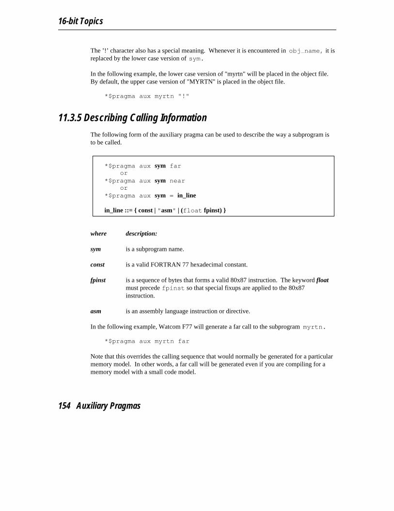
16-bit Topics
The ’!’ character also has a special meaning. Whenever it is encountered in obj name, it isreplaced by the lower case version of sym.
In the following example, the lower case version of "myrtn" will be placed in the object file.By default, the upper case version of "MYRTN" is placed in the object file.
*$pragma aux myrtn "!"
11.3.5 Describing Calling Information
The following form of the auxiliary pragma can be used to describe the way a subprogram isto be called.
*$pragma aux sym faror
*$pragma aux sym nearor
*$pragma aux sym = in_line
in_line ::= { const | "asm" | (float fpinst) }
where description:
sym is a subprogram name.
const is a valid FORTRAN 77 hexadecimal constant.
fpinst is a sequence of bytes that forms a valid 80x87 instruction. The keyword floatmust precede fpinst so that special fixups are applied to the 80x87instruction.
asm is an assembly language instruction or directive.
In the following example, Watcom F77 will generate a far call to the subprogram myrtn. *$pragma aux myrtn far
Note that this overrides the calling sequence that would normally be generated for a particularmemory model. In other words, a far call will be generated even if you are compiling for amemory model with a small code model.
154 Auxiliary Pragmas
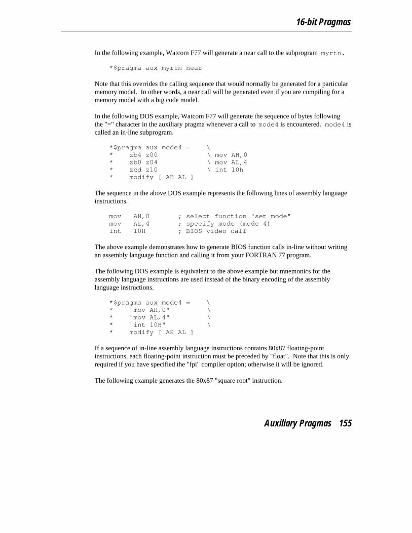
16-bit Pragmas
In the following example, Watcom F77 will generate a near call to the subprogram myrtn. *$pragma aux myrtn near
Note that this overrides the calling sequence that would normally be generated for a particularmemory model. In other words, a near call will be generated even if you are compiling for amemory model with a big code model.
In the following DOS example, Watcom F77 will generate the sequence of bytes followingthe "=" character in the auxiliary pragma whenever a call to mode4 is encountered. mode4 iscalled an in-line subprogram.
*$pragma aux mode4 = \* zb4 z00 \ mov AH,0* zb0 z04 \ mov AL,4* zcd z10 \ int 10h* modify [ AH AL ]
The sequence in the above DOS example represents the following lines of assembly languageinstructions.
mov AH,0 ; select function "set mode"mov AL,4 ; specify mode (mode 4)int 10H ; BIOS video call
The above example demonstrates how to generate BIOS function calls in-line without writingan assembly language function and calling it from your FORTRAN 77 program.
The following DOS example is equivalent to the above example but mnemonics for theassembly language instructions are used instead of the binary encoding of the assemblylanguage instructions.
*$pragma aux mode4 = \* "mov AH,0" \* "mov AL,4" \* "int 10H" \* modify [ AH AL ]
If a sequence of in-line assembly language instructions contains 80x87 floating-pointinstructions, each floating-point instruction must be preceded by "float". Note that this is onlyrequired if you have specified the "fpi" compiler option; otherwise it will be ignored.
The following example generates the 80x87 "square root" instruction.
Auxiliary Pragmas 155
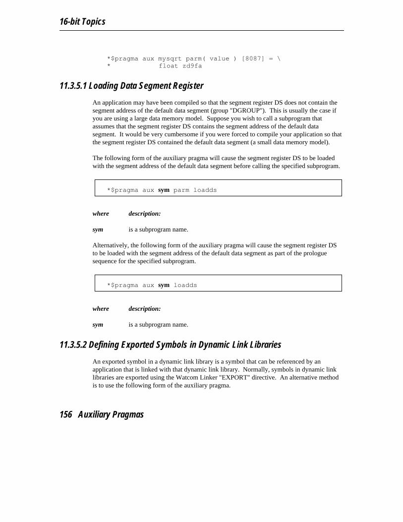
16-bit Topics
*$pragma aux mysqrt parm( value ) [8087] = \* float zd9fa
11.3.5.1 Loading Data Segment Register
An application may have been compiled so that the segment register DS does not contain thesegment address of the default data segment (group "DGROUP"). This is usually the case ifyou are using a large data memory model. Suppose you wish to call a subprogram thatassumes that the segment register DS contains the segment address of the default datasegment. It would be very cumbersome if you were forced to compile your application so thatthe segment register DS contained the default data segment (a small data memory model).
The following form of the auxiliary pragma will cause the segment register DS to be loadedwith the segment address of the default data segment before calling the specified subprogram.
*$pragma aux sym parm loadds
where description:
sym is a subprogram name.
Alternatively, the following form of the auxiliary pragma will cause the segment register DSto be loaded with the segment address of the default data segment as part of the prologuesequence for the specified subprogram.
*$pragma aux sym loadds
where description:
sym is a subprogram name.
11.3.5.2 Defining Exported Symbols in Dynamic Link Libraries
An exported symbol in a dynamic link library is a symbol that can be referenced by anapplication that is linked with that dynamic link library. Normally, symbols in dynamic linklibraries are exported using the Watcom Linker "EXPORT" directive. An alternative methodis to use the following form of the auxiliary pragma.
156 Auxiliary Pragmas

16-bit Pragmas
*$pragma aux sym export
where description:
sym is a subprogram name.
11.3.5.3 Defining Windows Callback Functions
When compiling a Microsoft Windows application, you must use the "windows" option sothat special prologue/epilogue sequences are generated. Furthermore, callback functionsrequire larger prologue/epilogue sequences than those generated when the "windows"compiler option is specified. The following form of the auxiliary pragma will cause acallback prologue/epilogue sequence to be generated for a callback function when compiledusing the "windows" option.
*$pragma aux sym export
where description:
sym is a callback function name.
11.3.6 Describing Argument Information
Using auxiliary pragmas, you can describe the calling convention that Watcom F77 is to usefor calling subprograms. This is particularly useful when interfacing to subprograms thathave been compiled by other compilers or subprograms written in other programminglanguages.
The general form of an auxiliary pragma that describes argument passing is the following.
Auxiliary Pragmas 157
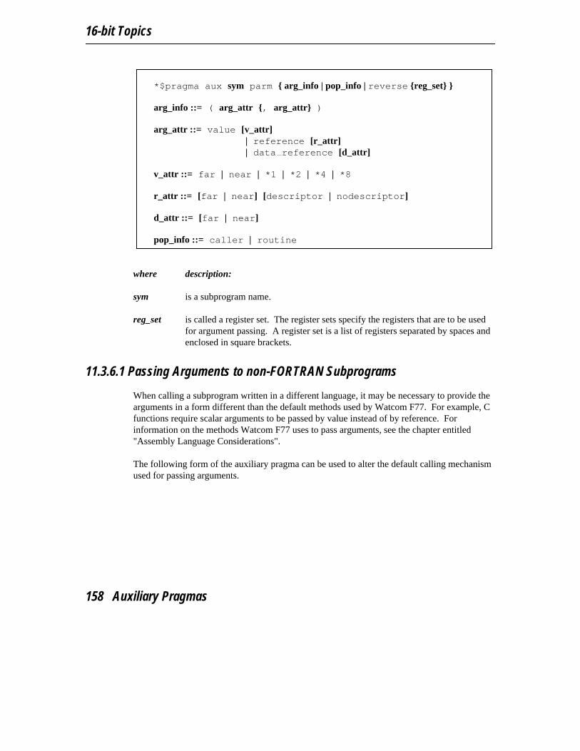
16-bit Topics
*$pragma aux sym parm { arg_info | pop_info | reverse {reg_set} }
arg_info ::= ( arg_attr {, arg_attr} )
arg_attr ::= value [v_attr]| reference [r_attr]| data reference [d_attr]
v_attr ::= far | near | *1 | *2 | *4 | *8
r_attr ::= [far | near] [descriptor | nodescriptor]
d_attr ::= [far | near]
pop_info ::= caller | routine
where description:
sym is a subprogram name.
reg_set is called a register set. The register sets specify the registers that are to be usedfor argument passing. A register set is a list of registers separated by spaces andenclosed in square brackets.
11.3.6.1 Passing Arguments to non-FORTRAN Subprograms
When calling a subprogram written in a different language, it may be necessary to provide thearguments in a form different than the default methods used by Watcom F77. For example, Cfunctions require scalar arguments to be passed by value instead of by reference. Forinformation on the methods Watcom F77 uses to pass arguments, see the chapter entitled"Assembly Language Considerations".
The following form of the auxiliary pragma can be used to alter the default calling mechanismused for passing arguments.
158 Auxiliary Pragmas

16-bit Pragmas
*$pragma aux sym parm ( arg_attr {, arg_attr} )
arg_attr ::= value [v_attr]| reference [r_attr]| data reference [d_attr]
v_attr ::= far | near | *1 | *2 | *4 | *8
r_attr ::= [far | near] [descriptor | nodescriptor]
d_attr ::= [far | near]
where description:
sym is a subprogram name.
REFERENCE specifies that arguments are to be passed by reference. For non-characterarguments, the address is a pointer to the data. For character arguments, theaddress is a pointer to a string descriptor. See the chapter entitled "AssemblyLanguage Considerations" for a description of a string descriptor. This is thedefault calling mechanism. If "NEAR" or "FAR" is specified, a near pointer orfar pointer is passed regardless of the memory model used at compile-time.
If the "DESCRIPTOR" attribute is specified, a pointer to the string descriptor ispassed. This is the default. If the "NODESCRIPTOR" attribute is specified, apointer to the the actual character data is passed instead of a pointer to the stringdescriptor.
DATA_REFERENCE specifies that arguments are to be passed by data reference. Fornon-character items, this is identical to passing by reference. For characteritems, a pointer to the actual character data (instead of the string descriptor) ispassed. If "NEAR" or "FAR" is specified, a near pointer or far pointer is passedregardless of the memory model used at compile-time.
VALUE specifies that arguments are to be passed by value. Character arguments aretreated specially when passed by value. Instead of passing a pointer to a stringdescriptor, a pointer to the actual character data is passed. See the chapterentitled "Assembly Language Considerations" for a description of a stringdescriptor.
Auxiliary Pragmas 159

16-bit Topics
Notes:
1. Arrays and subprograms are always passed by reference, regardless of the argumentattribute specified.
2. When character arguments are passed by reference, the address of a stringdescriptor is passed. The string descriptor contains the address of the actualcharacter data and the number of characters. When character arguments are passedby value or data reference, the address of the actual character data is passed insteadof the address of a string descriptor. Character arguments are passed by value byspecifying the "VALUE" or "DATA_REFERENCE" attribute. If "NEAR" or"FAR" is specified, a near pointer or far pointer to the character data is passedregardless of the memory model used at compile-time.
3. When complex arguments are passed by value, the real part and the imaginary partare passed as two separate arguments.
4. When an argument is a user-defined structure and is passed by value, a copy of thestructure is made and passed as an argument.
5. For scalar arguments, arguments of type INTEGER*1, INTEGER*2,INTEGER*4, REAL or DOUBLE PRECISION, a length specification can bespecified when the "VALUE" attribute is specified to pass the argument by value.This length specification refers to the size of the argument; the compiler willconvert the actual argument to a type that matches the size. For example, if anargument of type REAL is passed to a subprogram that has an argument attributeof "VALUE*8", the argument will be converted to DOUBLE PRECISION. If anargument of type DOUBLE PRECISION is passed to a subprogram that has anargument attribute of "VALUE*4", the argument will be converted to REAL. If anargument of type INTEGER*4 is passed to a subprogram that has an argumentattribute of "VALUE*2" or VALUE*1, the argument will be converted toINTEGER*2 or INTEGER*1. If an argument of type INTEGER*2 is passed toa subprogram that has an argument attribute of "VALUE*4 or VALUE*1", theargument will be converted to INTEGER*4 or INTEGER*1. If an argument oftype INTEGER*1 is passed to a subprogram that has an argument attribute of"VALUE*4 or VALUE*2", the argument will be converted to INTEGER*4 orINTEGER*2.
6. If the number of arguments exceeds the number of entries in the argument-attributelist, the last attribute will be assumed for the remaining arguments.
Consider the following example.
160 Auxiliary Pragmas
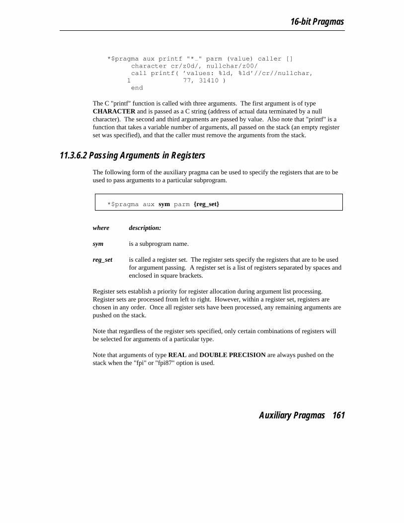
16-bit Pragmas
*$pragma aux printf "* " parm (value) caller []
character cr/z0d/, nullchar/z00/call printf( ’values: %ld, %ld’//cr//nullchar,
1 77, 31410 )end
The C "printf" function is called with three arguments. The first argument is of typeCHARACTER and is passed as a C string (address of actual data terminated by a nullcharacter). The second and third arguments are passed by value. Also note that "printf" is afunction that takes a variable number of arguments, all passed on the stack (an empty registerset was specified), and that the caller must remove the arguments from the stack.
11.3.6.2 Passing Arguments in Registers
The following form of the auxiliary pragma can be used to specify the registers that are to beused to pass arguments to a particular subprogram.
*$pragma aux sym parm {reg_set}
where description:
sym is a subprogram name.
reg_set is called a register set. The register sets specify the registers that are to be usedfor argument passing. A register set is a list of registers separated by spaces andenclosed in square brackets.
Register sets establish a priority for register allocation during argument list processing.Register sets are processed from left to right. However, within a register set, registers arechosen in any order. Once all register sets have been processed, any remaining arguments arepushed on the stack.
Note that regardless of the register sets specified, only certain combinations of registers willbe selected for arguments of a particular type.
Note that arguments of type REAL and DOUBLE PRECISION are always pushed on thestack when the "fpi" or "fpi87" option is used.
Auxiliary Pragmas 161
16-bit Topics
DOUBLE PRECISIONArguments of type DOUBLE PRECISION, when passed by value, can only bepassed in the following register combination: AX:BX:CX:DX. For example, ifthe following register set was specified for a routine having an argument of typeDOUBLE PRECISION,
[AX BX SI DI]
the argument would be pushed on the stack since a valid register combinationfor 8-byte arguments is not contained in the register set. Note that this methodfor passing arguments of type DOUBLE PRECISION is supported only whenthe "fpc" option is used. Note that this argument passing method does notinclude arguments of type COMPLEX*8 or user-defined structures whose sizeis 8 bytes when these arguments are passed by value.
far pointer A far pointer can only be passed in one of the following register pairs: DX:AX,CX:BX, CX:AX, CX:SI, DX:BX, DI:AX, CX:DI, DX:SI, DI:BX, SI:AX,CX:DX, DX:DI, DI:SI, SI:BX, BX:AX, DS:CX, DS:DX, DS:DI, DS:SI,DS:BX, DS:AX, ES:CX, ES:DX, ES:DI, ES:SI, ES:BX or ES:AX. Forexample, if a far pointer is passed to a function with the following register set,
[ES BP]
the argument would be pushed on the stack since a valid register combinationfor a far pointer is not contained in the register set. Far pointers are used to passarguments by reference in a big data memory model.
INTEGER*4, REALThe only registers that will be assigned to 4-byte arguments (e.g., arguments oftype INTEGER*4, when passed by value) are: DX:AX, CX:BX, CX:AX,CX:SI, DX:BX, DI:AX, CX:DI, DX:SI, DI:BX, SI:AX, CX:DX, DX:DI, DI:SI,SI:BX and BX:AX. For example, if the following register set was specified fora routine with one argument of type INTEGER*4,
[ES DI]
the argument would be pushed on the stack since a valid register combinationfor 4-byte arguments is not contained in the register set. Note that this argumentpassing method includes arguments of type REAL but only when the "fpc"option is used.
INTEGER*2The only registers that will be assigned to 2-byte arguments (e.g., arguments oftype INTEGER*2 when passed by value or arguments passed by reference in a
162 Auxiliary Pragmas

16-bit Pragmas
small data memory model) are: AX, BX, CX, DX, SI and DI. For example, ifthe following register set was specified for a routine with one argument of typeINTEGER*2,
[BP]
the argument would be pushed on the stack since a valid register combinationfor 2-byte arguments is not contained in the register set.
INTEGER*1Arguments whose size is 1 byte (e.g., arguments of type INTEGER*1 whenpassed by value) are promoted to 2 bytes and are then assigned registers as ifthey were 2-byte arguments.
others Arguments that do not fall into one of the above categories cannot be passed inregisters and are pushed on the stack. Once an argument has been assigned aposition on the stack, all remaining arguments will be assigned a position on thestack even if all register sets have not yet been exhausted.
Notes:
1. The default register set is [AX BX CX DX].
2. Specifying registers AH and AL is equivalent to specifying register AX.Specifying registers DH and DL is equivalent to specifying register DX.Specifying registers CH and CL is equivalent to specifying register CX. Specifyingregisters BH and BL is equivalent to specifying register BX.
3. If you are compiling for a memory model with a small data model, any registercombination containing register DS becomes illegal. In a small data model,segment register DS must remain unchanged as it points to the program’s datasegment.
Consider the following example. *$pragma aux myrtn parm (value) \* [ax bx cx dx] [bp si]
Suppose myrtn is a routine with 3 arguments each of type INTEGER. Note that thearguments are passed by value.
1. The first argument will be passed in the register pair DX:AX.2. The second argument will be passed in the register pair CX:BX.
Auxiliary Pragmas 163
16-bit Topics
3. The third argument will be pushed on the stack since BP:SI is not a valid registerpair for arguments of type INTEGER.
It is possible for registers from the second register set to be used before registers from the firstregister set are used. Consider the following example.
*$pragma aux myrtn parm (value) \* [ax bx cx dx] [si di]
Suppose myrtn is a routine with 3 arguments, the first of type INTEGER and the secondand third of type INTEGER. Note that all arguments are passed by value.
1. The first argument will be passed in the register AX.2. The second argument will be passed in the register pair CX:BX.3. The third argument will be passed in the register set DI:SI.
Note that registers are no longer selected from a register set after registers are selected fromsubsequent register sets, even if all registers from the original register set have not beenexhausted.
An empty register set is permitted. All subsequent register sets appearing after an emptyregister set are ignored; all remaining arguments are pushed on the stack.
Notes:
1. If a single empty register set is specified, all arguments are passed on the stack.
2. If no register set is specified, the default register set [AX BX CX DX] is used.
11.3.6.3 Forcing Arguments into Specific Registers
It is possible to force arguments into specific registers. Suppose you have a subprogram, say"mycopy", that copies data. The first argument is the source, the second argument is thedestination, and the third argument is the length to copy. If we want the first argument to bepassed in the register SI, the second argument to be passed in register DI and the thirdargument to be passed in register CX, the following auxiliary pragma can be used.
*$pragma aux mycopy parm (value) \* [DI] [SI] [CX]
character*10 dstcall mycopy( dst, ’0123456789’, 10 )...end
164 Auxiliary Pragmas
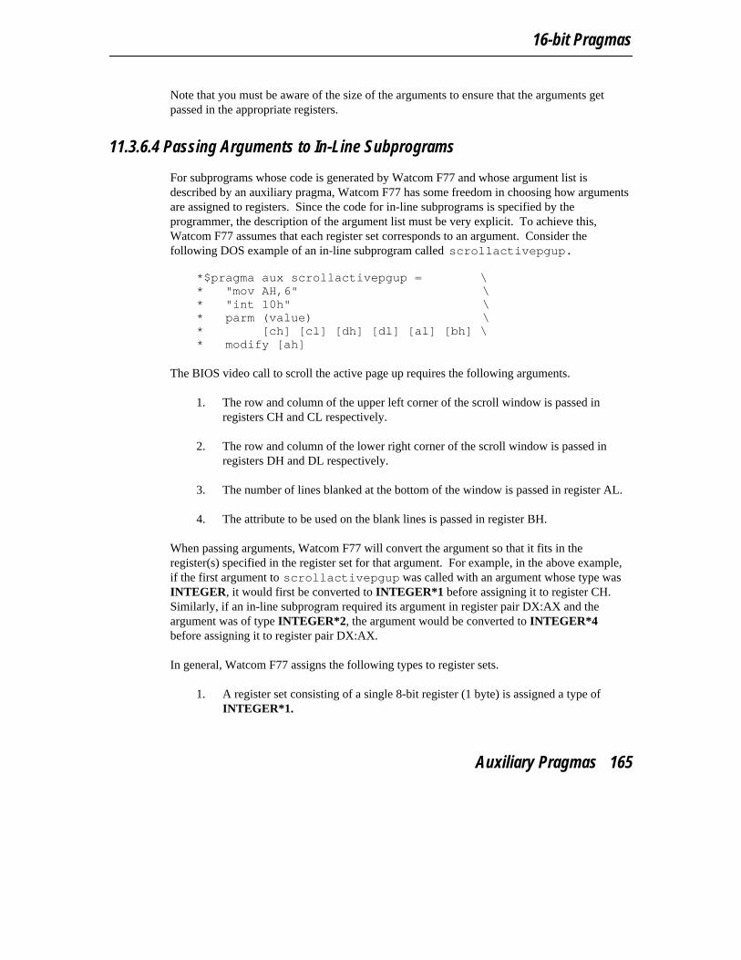
16-bit Pragmas
Note that you must be aware of the size of the arguments to ensure that the arguments getpassed in the appropriate registers.
11.3.6.4 Passing Arguments to In-Line Subprograms
For subprograms whose code is generated by Watcom F77 and whose argument list isdescribed by an auxiliary pragma, Watcom F77 has some freedom in choosing how argumentsare assigned to registers. Since the code for in-line subprograms is specified by theprogrammer, the description of the argument list must be very explicit. To achieve this,Watcom F77 assumes that each register set corresponds to an argument. Consider thefollowing DOS example of an in-line subprogram called scrollactivepgup.
*$pragma aux scrollactivepgup = \* "mov AH,6" \* "int 10h" \* parm (value) \* [ch] [cl] [dh] [dl] [al] [bh] \* modify [ah]
The BIOS video call to scroll the active page up requires the following arguments.
1. The row and column of the upper left corner of the scroll window is passed inregisters CH and CL respectively.
2. The row and column of the lower right corner of the scroll window is passed inregisters DH and DL respectively.
3. The number of lines blanked at the bottom of the window is passed in register AL.
4. The attribute to be used on the blank lines is passed in register BH.
When passing arguments, Watcom F77 will convert the argument so that it fits in theregister(s) specified in the register set for that argument. For example, in the above example,if the first argument to scrollactivepgup was called with an argument whose type wasINTEGER, it would first be converted to INTEGER*1 before assigning it to register CH.Similarly, if an in-line subprogram required its argument in register pair DX:AX and theargument was of type INTEGER*2, the argument would be converted to INTEGER*4before assigning it to register pair DX:AX.
In general, Watcom F77 assigns the following types to register sets.
1. A register set consisting of a single 8-bit register (1 byte) is assigned a type ofINTEGER*1.
Auxiliary Pragmas 165

16-bit Topics
2. A register set consisting of a single 16-bit register (2 bytes) is assigned a type ofINTEGER*2.
3. A register set consisting of two 16-bit registers (4 bytes) is assigned a type ofINTEGER*4.
4. A register set consisting of four 16-bit registers (8 bytes) is assigned a type ofDOUBLE PRECISION.
If the size of an integer argument is larger than the size specified by the register set, theargument will be truncated to the required size. If the size of an integer argument is smallerthan the size specified by the register set, the argument will be padded (to the left) with zeros.
11.3.6.5 Removing Arguments from the Stack
The following form of the auxiliary pragma specifies who removes from the stack argumentsthat were pushed on the stack.
*$pragma aux sym parm (caller | routine)
where description:
sym is a subprogram name.
"caller" specifies that the caller will pop the arguments from the stack; "routine" specifies thatthe called routine will pop the arguments from the stack. If "caller" or "routine" is omitted,"routine" is assumed unless the default has been changed in a previous auxiliary pragma, inwhich case the new default is assumed.
Consider the following example. It describes the pragma required to call the C "printf"function.
*$pragma aux printf "* " parm (value) caller []
character cr/z0d/, nullchar/z00/call printf( ’value is %ld’//cr//nullchar,
1 7143 )end
The first argument must be passed as a C string, a pointer to the actual character dataterminated by a null character. By default, the address of a string descriptor is passed forarguments of type CHARACTER. See the chapter entitled "Assembly LanguageConsiderations" for more information on string descriptors. The second argument is of type
166 Auxiliary Pragmas
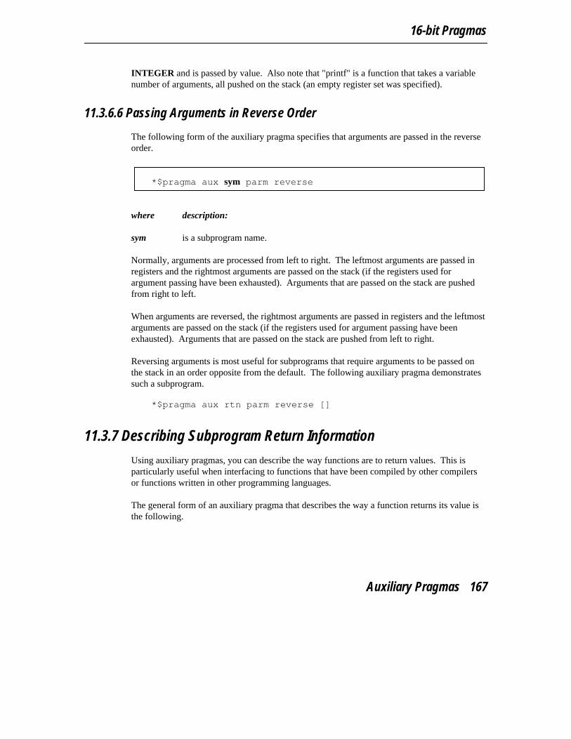
16-bit Pragmas
INTEGER and is passed by value. Also note that "printf" is a function that takes a variablenumber of arguments, all pushed on the stack (an empty register set was specified).
11.3.6.6 Passing Arguments in Reverse Order
The following form of the auxiliary pragma specifies that arguments are passed in the reverseorder.
*$pragma aux sym parm reverse
where description:
sym is a subprogram name.
Normally, arguments are processed from left to right. The leftmost arguments are passed inregisters and the rightmost arguments are passed on the stack (if the registers used forargument passing have been exhausted). Arguments that are passed on the stack are pushedfrom right to left.
When arguments are reversed, the rightmost arguments are passed in registers and the leftmostarguments are passed on the stack (if the registers used for argument passing have beenexhausted). Arguments that are passed on the stack are pushed from left to right.
Reversing arguments is most useful for subprograms that require arguments to be passed onthe stack in an order opposite from the default. The following auxiliary pragma demonstratessuch a subprogram.
*$pragma aux rtn parm reverse []
11.3.7 Describing Subprogram Return Information
Using auxiliary pragmas, you can describe the way functions are to return values. This isparticularly useful when interfacing to functions that have been compiled by other compilersor functions written in other programming languages.
The general form of an auxiliary pragma that describes the way a function returns its value isthe following.
Auxiliary Pragmas 167

16-bit Topics
*$pragma aux sym value {no8087 | reg_set | struct_info} struct_info ::= struct {float | struct | (routine | caller) | reg_set}
where description:
sym is a function name.
reg_set is called a register set. The register sets specify the registers that are to be usedfor argument passing. A register set is a list of registers separated by spaces andenclosed in square brackets.
11.3.7.1 Returning Subprogram Values in Registers
The following form of the auxiliary pragma can be used to specify the registers that are to beused to return a function’s value.
*$pragma aux sym value reg_set
where description:
sym is a subprogram name.
reg_set is a register set.
Note that the method described below for returning values of type REAL or DOUBLEPRECISION is supported only when the "fpc" option is used.
Depending on the type of the return value, only certain registers are allowed in reg_set.
1-byte For 1-byte return values, only the following registers are allowed: AL, AH, DL,DH, BL, BH, CL or CH. If no register set is specified, register AL will be used.
2-byte For 2-byte return values, only the following registers are allowed: AX, DX, BX,CX, SI or DI. If no register set is specified, register AX will be used.
4-byte For 4-byte return values (except far pointers), only the following register pairsare allowed: DX:AX, CX:BX, CX:AX, CX:SI, DX:BX, DI:AX, CX:DI, DX:SI,DI:BX, SI:AX, CX:DX, DX:DI, DI:SI, SI:BX or BX:AX. If no register set is
168 Auxiliary Pragmas

16-bit Pragmas
specified, registers DX:AX will be used. This form of the auxiliary pragma islegal for functions of type REAL when using the "fpc" option only.
far pointer For functions that return far pointers, the following register pairs are allowed:DX:AX, CX:BX, CX:AX, CX:SI, DX:BX, DI:AX, CX:DI, DX:SI, DI:BX,SI:AX, CX:DX, DX:DI, DI:SI, SI:BX, BX:AX, DS:CX, DS:DX, DS:DI, DS:SI,DS:BX, DS:AX, ES:CX, ES:DX, ES:DI, ES:SI, ES:BX or ES:AX. If noregister set is specified, the registers DX:AX will be used.
8-byte For 8-byte return values (including functions of type DOUBLE PRECISION),only the following register combination is allowed: AX:BX:CX:DX. If noregister set is specified, the registers AX:BX:CX:DX will be used. This form ofthe auxiliary pragma is legal for functions of type DOUBLE PRECISIONwhen using the "fpc" option only.
Notes:
1. An empty register set is not allowed.
2. If you are compiling for a memory model which has a small data model, any of theabove register combinations containing register DS becomes illegal. In a smalldata model, segment register DS must remain unchanged as it points to theprogram’s data segment.
11.3.7.2 Returning Structures and Complex Numbers
Typically, structures and complex numbers are not returned in registers. Instead, the callerallocates space on the stack for the return value and sets register SI to point to it. The calledroutine then places the return value at the location pointed to by register SI.
Complex numbers are not scalars but rather an ordered pair of real numbers. One can alsoview complex numbers as a structure containing two real numbers.
The following form of the auxiliary pragma can be used to specify the register that is to beused to point to the return value.
*$pragma aux sym value struct (caller|routine) reg_set
Auxiliary Pragmas 169

16-bit Topics
where description:
sym is a subprogram name.
reg_set is a register set.
"caller" specifies that the caller will allocate memory for the return value. The address of thememory allocated for the return value is placed in the register specified in the register set bythe caller before the function is called. If an empty register set is specified, the address of thememory allocated for the return value will be pushed on the stack immediately before the calland will be returned in register AX by the called routine. It is assumed that the memory forthe return value is allocated from the stack segment (the stack segment is contained insegment register SS).
"routine" specifies that the called routine will allocate memory for the return value. Uponreturning to the caller, the register specified in the register set will contain the address of thereturn value. An empty register set is not allowed.
Only the following registers are allowed in the register set: AX, DX, BX, CX, SI or DI. Notethat in a big data model, the address in the return register is assumed to be in the segmentspecified by the value in the SS segment register.
If the size of the structure being returned is 1, 2 or 4 bytes, it will be returned in registers. Thereturn register will be selected from the register set in the following way.
1. A 1-byte structure will be returned in one of the following registers: AL, AH, DL,DH, BL, BH, CL or CH. If no register set is specified, register AL will be used.
2. A 2-byte structure will be returned in one of the following registers: AX, DX, BX,CX, SI or DI. If no register set is specified, register AX will be used.
3. A 4-byte structure will be returned in one of the following register pairs: DX:AX,CX:BX, CX:AX, CX:SI, DX:BX, DI:AX, CX:DI, DX:SI, DI:BX, SI:AX, CX:DX,DX:DI, DI:SI, SI:BX or BX:AX. If no register set is specified, register pairDX:AX will be used.
The following form of the auxiliary pragma can be used to specify that structures whose sizeis 1, 2 or 4 bytes are not to be returned in registers. Instead, the caller will allocate space onthe stack for the structure return value and point register SI to it.
170 Auxiliary Pragmas

16-bit Pragmas
*$pragma aux sym value struct struct
where description:
sym is a subprogram name.
11.3.7.3 Returning Floating-Point Data
There are a few ways available for specifying how the value for a function whose type isREAL or DOUBLE PRECISION is to be returned.
The following form of the auxiliary pragma can be used to specify that function return valueswhose type is REAL or DOUBLE PRECISION are not to be returned in registers. Instead,the caller will allocate space on the stack for the return value and point register SI to it.
*$pragma aux sym value struct float
where description:
sym is a function name.
In other words, floating-point values are to be returned in the same way complex numbers arereturned.
The following form of the auxiliary pragma can be used to specify that function return valueswhose type is REAL or DOUBLE PRECISION are not to be returned in 80x87 registerswhen compiling with the "fpi" or "fpi87" option. Instead, the value will be returned in 80x86registers. This is the default behaviour for the "fpc" option. Function return values whosetype is REAL will be returned in registers DX:AX. Function return values whose type isDOUBLE PRECISION will be returned in registers AX:BX:CX:DX. This is the defaultmethod for the "fpc" option.
*$pragma aux sym value no8087
Auxiliary Pragmas 171

16-bit Topics
where description:
sym is a function name.
The following form of the auxiliary pragma can be used to specify that function return valueswhose type is REAL or DOUBLE PRECISION are to be returned in ST(0) when compilingwith the "fpi" or "fpi87" option. This form of the auxiliary pragma is not legal for the "fpc"option.
*$pragma aux sym value [8087]
where description:
sym is a function name.
11.3.8 A Subprogram that Never Returns
The following form of the auxiliary pragma can be used to describe a subprogram that doesnot return to the caller.
*$pragma aux sym aborts
where description:
sym is a subprogram name.
Consider the following example. *$pragma aux exitrtn aborts
...call exitrtn()end
exitrtn is defined to be a function that does not return. For example, it may call exit toreturn to the system. In this case, Watcom F77 generates a "jmp" instruction instead of a"call" instruction to invoke exitrtn.
172 Auxiliary Pragmas
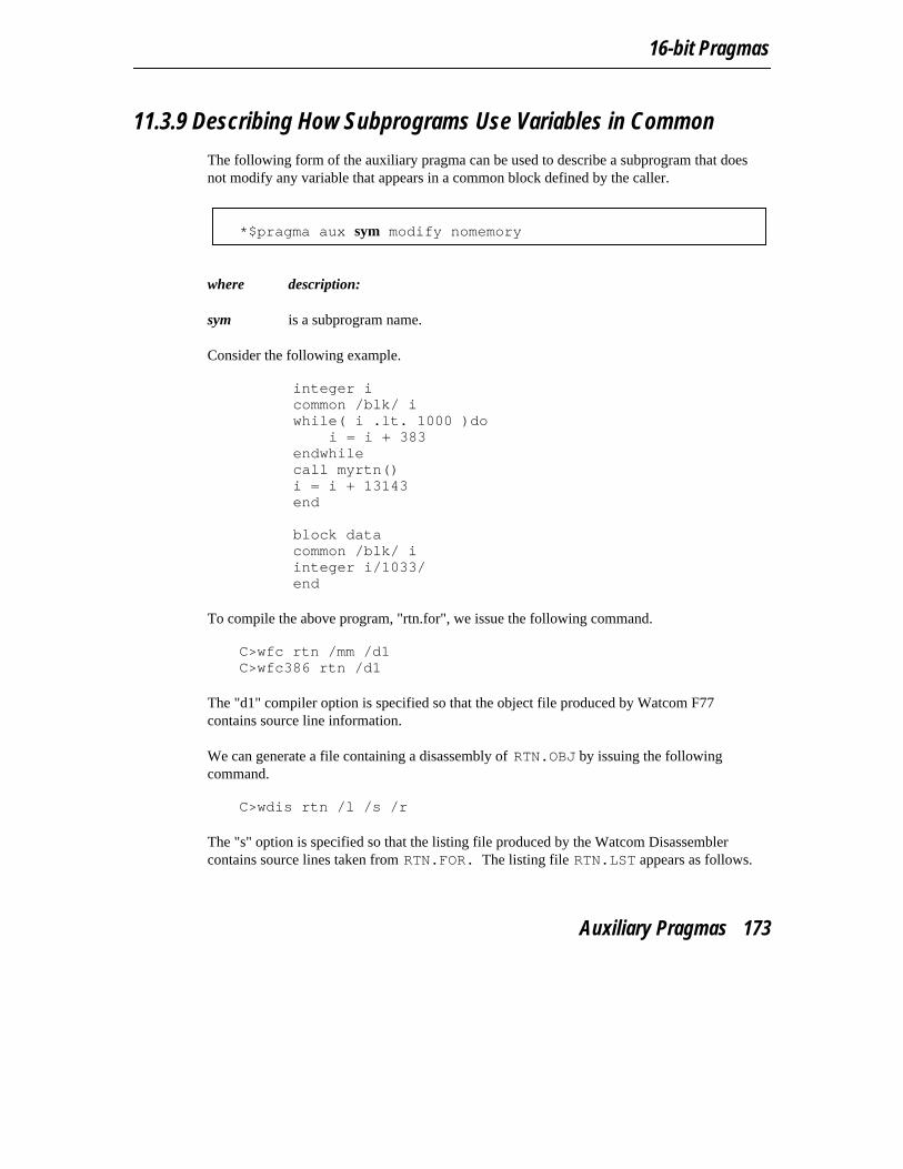
16-bit Pragmas
11.3.9 Describing How Subprograms Use Variables in Common
The following form of the auxiliary pragma can be used to describe a subprogram that doesnot modify any variable that appears in a common block defined by the caller.
*$pragma aux sym modify nomemory
where description:
sym is a subprogram name.
Consider the following example.
integer icommon /blk/ iwhile( i .lt. 1000 )do
i = i + 383endwhilecall myrtn()i = i + 13143end
block datacommon /blk/ iinteger i/1033/end
To compile the above program, "rtn.for", we issue the following command. C>wfc rtn /mm /d1C>wfc386 rtn /d1
The "d1" compiler option is specified so that the object file produced by Watcom F77contains source line information.
We can generate a file containing a disassembly of RTN.OBJ by issuing the followingcommand.
C>wdis rtn /l /s /r
The "s" option is specified so that the listing file produced by the Watcom Disassemblercontains source lines taken from RTN.FOR. The listing file RTN.LST appears as follows.
Auxiliary Pragmas 173
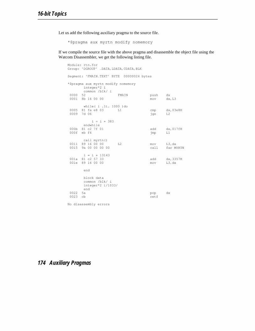
16-bit Topics
Let us add the following auxiliary pragma to the source file. *$pragma aux myrtn modify nomemory
If we compile the source file with the above pragma and disassemble the object file using theWatcom Disassembler, we get the following listing file.
Module: rtn.forGroup: ’DGROUP’ DATA,LDATA,CDATA,BLK
Segment: ’FMAIN TEXT’ BYTE 00000024 bytes
*$pragma aux myrtn modify nomemoryinteger*2 icommon /blk/ i
0000 52 FMAIN push dx0001 8b 16 00 00 mov dx,L3
while( i .lt. 1000 )do0005 81 fa e8 03 L1 cmp dx,03e8H0009 7d 06 jge L2
i = i + 383endwhile
000b 81 c2 7f 01 add dx,017fH000f eb f4 jmp L1
call myrtn()0011 89 16 00 00 L2 mov L3,dx0015 9a 00 00 00 00 call far MYRTN
i = i + 13143001a 81 c2 57 33 add dx,3357H001e 89 16 00 00 mov L3,dx
end
block datacommon /blk/ iinteger*2 i/1033/end
0022 5a pop dx0023 cb retf
No disassembly errors
174 Auxiliary Pragmas
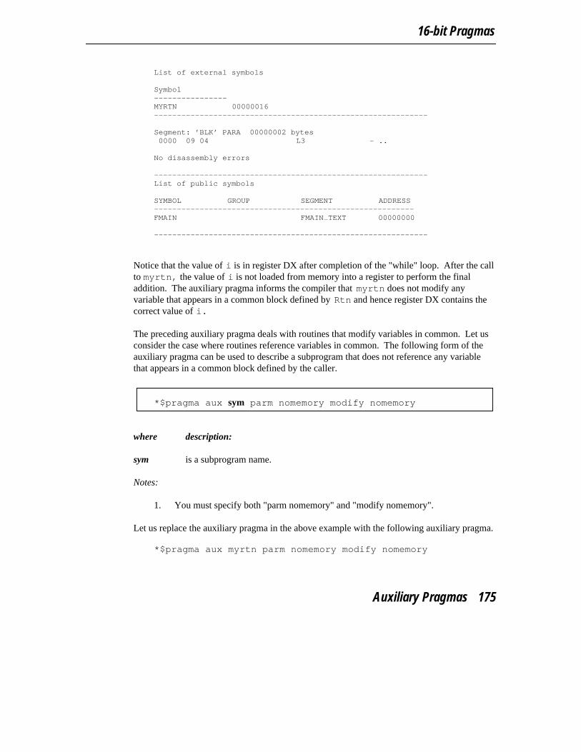
16-bit Pragmas
List of external symbols
Symbol----------------MYRTN 00000016------------------------------------------------------------
Segment: ’BLK’ PARA 00000002 bytes0000 09 04 L3 - ..
No disassembly errors
------------------------------------------------------------List of public symbols
SYMBOL GROUP SEGMENT ADDRESS---------------------------------------------------------FMAIN FMAIN TEXT 00000000
------------------------------------------------------------
Notice that the value of i is in register DX after completion of the "while" loop. After the callto myrtn, the value of i is not loaded from memory into a register to perform the finaladdition. The auxiliary pragma informs the compiler that myrtn does not modify anyvariable that appears in a common block defined by Rtn and hence register DX contains thecorrect value of i.
The preceding auxiliary pragma deals with routines that modify variables in common. Let usconsider the case where routines reference variables in common. The following form of theauxiliary pragma can be used to describe a subprogram that does not reference any variablethat appears in a common block defined by the caller.
*$pragma aux sym parm nomemory modify nomemory
where description:
sym is a subprogram name.
Notes:
1. You must specify both "parm nomemory" and "modify nomemory".
Let us replace the auxiliary pragma in the above example with the following auxiliary pragma. *$pragma aux myrtn parm nomemory modify nomemory
Auxiliary Pragmas 175
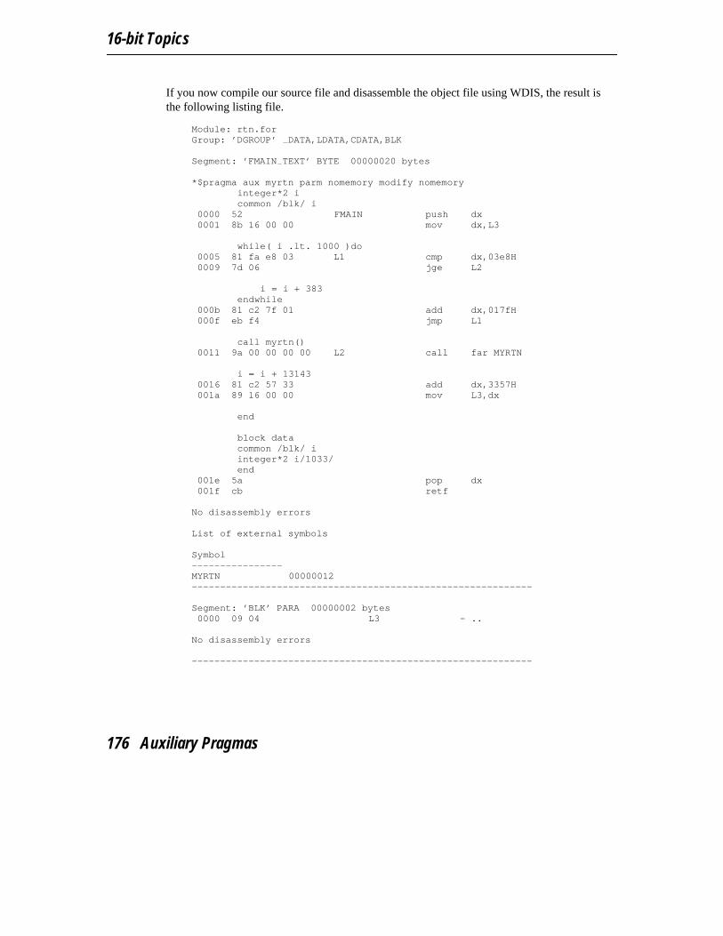
16-bit Topics
If you now compile our source file and disassemble the object file using WDIS, the result isthe following listing file.
Module: rtn.forGroup: ’DGROUP’ DATA,LDATA,CDATA,BLK
Segment: ’FMAIN TEXT’ BYTE 00000020 bytes
*$pragma aux myrtn parm nomemory modify nomemoryinteger*2 icommon /blk/ i
0000 52 FMAIN push dx0001 8b 16 00 00 mov dx,L3
while( i .lt. 1000 )do0005 81 fa e8 03 L1 cmp dx,03e8H0009 7d 06 jge L2
i = i + 383endwhile
000b 81 c2 7f 01 add dx,017fH000f eb f4 jmp L1
call myrtn()0011 9a 00 00 00 00 L2 call far MYRTN
i = i + 131430016 81 c2 57 33 add dx,3357H001a 89 16 00 00 mov L3,dx
end
block datacommon /blk/ iinteger*2 i/1033/end
001e 5a pop dx001f cb retf
No disassembly errors
List of external symbols
Symbol----------------MYRTN 00000012------------------------------------------------------------
Segment: ’BLK’ PARA 00000002 bytes0000 09 04 L3 - ..
No disassembly errors
------------------------------------------------------------
176 Auxiliary Pragmas
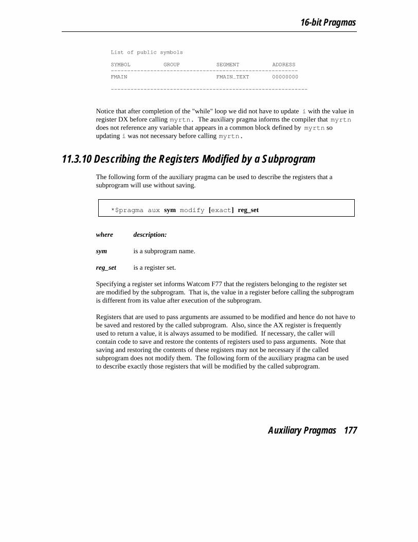
16-bit Pragmas
List of public symbols
SYMBOL GROUP SEGMENT ADDRESS---------------------------------------------------------FMAIN FMAIN TEXT 00000000
------------------------------------------------------------
Notice that after completion of the "while" loop we did not have to update i with the value inregister DX before calling myrtn. The auxiliary pragma informs the compiler that myrtndoes not reference any variable that appears in a common block defined by myrtn soupdating i was not necessary before calling myrtn.
11.3.10 Describing the Registers Modified by a Subprogram
The following form of the auxiliary pragma can be used to describe the registers that asubprogram will use without saving.
*$pragma aux sym modify [exact] reg_set
where description:
sym is a subprogram name.
reg_set is a register set.
Specifying a register set informs Watcom F77 that the registers belonging to the register setare modified by the subprogram. That is, the value in a register before calling the subprogramis different from its value after execution of the subprogram.
Registers that are used to pass arguments are assumed to be modified and hence do not have tobe saved and restored by the called subprogram. Also, since the AX register is frequentlyused to return a value, it is always assumed to be modified. If necessary, the caller willcontain code to save and restore the contents of registers used to pass arguments. Note thatsaving and restoring the contents of these registers may not be necessary if the calledsubprogram does not modify them. The following form of the auxiliary pragma can be usedto describe exactly those registers that will be modified by the called subprogram.
Auxiliary Pragmas 177
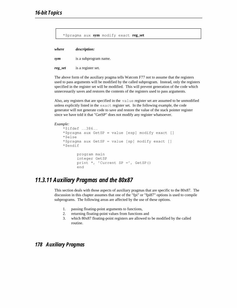
16-bit Topics
*$pragma aux sym modify exact reg_set
where description:
sym is a subprogram name.
reg_set is a register set.
The above form of the auxiliary pragma tells Watcom F77 not to assume that the registersused to pass arguments will be modified by the called subprogram. Instead, only the registersspecified in the register set will be modified. This will prevent generation of the code whichunnecessarily saves and restores the contents of the registers used to pass arguments.
Also, any registers that are specified in the value register set are assumed to be unmodifiedunless explicitly listed in the exact register set. In the following example, the codegenerator will not generate code to save and restore the value of the stack pointer registersince we have told it that "GetSP" does not modify any register whatsoever.
Example:*$ifdef 386*$pragma aux GetSP = value [esp] modify exact []*$else*$pragma aux GetSP = value [sp] modify exact []*$endif
program maininteger GetSPprint *, ’Current SP =’, GetSP()end
11.3.11 Auxiliary Pragmas and the 80x87
This section deals with those aspects of auxiliary pragmas that are specific to the 80x87. Thediscussion in this chapter assumes that one of the "fpi" or "fpi87" options is used to compilesubprograms. The following areas are affected by the use of these options.
1. passing floating-point arguments to functions,2. returning floating-point values from functions and3. which 80x87 floating-point registers are allowed to be modified by the called
routine.
178 Auxiliary Pragmas
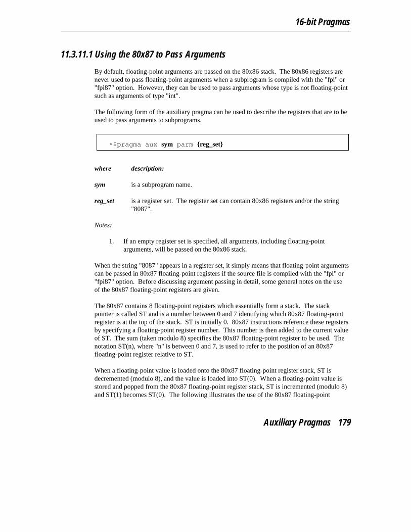
16-bit Pragmas
11.3.11.1 Using the 80x87 to Pass Arguments
By default, floating-point arguments are passed on the 80x86 stack. The 80x86 registers arenever used to pass floating-point arguments when a subprogram is compiled with the "fpi" or"fpi87" option. However, they can be used to pass arguments whose type is not floating-pointsuch as arguments of type "int".
The following form of the auxiliary pragma can be used to describe the registers that are to beused to pass arguments to subprograms.
*$pragma aux sym parm {reg_set}
where description:
sym is a subprogram name.
reg_set is a register set. The register set can contain 80x86 registers and/or the string"8087".
Notes:
1. If an empty register set is specified, all arguments, including floating-pointarguments, will be passed on the 80x86 stack.
When the string "8087" appears in a register set, it simply means that floating-point argumentscan be passed in 80x87 floating-point registers if the source file is compiled with the "fpi" or"fpi87" option. Before discussing argument passing in detail, some general notes on the useof the 80x87 floating-point registers are given.
The 80x87 contains 8 floating-point registers which essentially form a stack. The stackpointer is called ST and is a number between 0 and 7 identifying which 80x87 floating-pointregister is at the top of the stack. ST is initially 0. 80x87 instructions reference these registersby specifying a floating-point register number. This number is then added to the current valueof ST. The sum (taken modulo 8) specifies the 80x87 floating-point register to be used. Thenotation ST(n), where "n" is between 0 and 7, is used to refer to the position of an 80x87floating-point register relative to ST.
When a floating-point value is loaded onto the 80x87 floating-point register stack, ST isdecremented (modulo 8), and the value is loaded into ST(0). When a floating-point value isstored and popped from the 80x87 floating-point register stack, ST is incremented (modulo 8)and ST(1) becomes ST(0). The following illustrates the use of the 80x87 floating-point
Auxiliary Pragmas 179
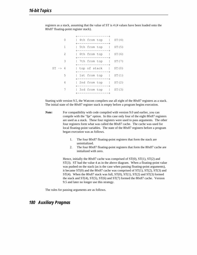
16-bit Topics
registers as a stack, assuming that the value of ST is 4 (4 values have been loaded onto the80x87 floating-point register stack).
+----------------+
0 | 4th from top | ST(4)+----------------+
1 | 5th from top | ST(5)+----------------+
2 | 6th from top | ST(6)+----------------+
3 | 7th from top | ST(7)+----------------+
ST -> 4 | top of stack | ST(0)+----------------+
5 | 1st from top | ST(1)+----------------+
6 | 2nd from top | ST(2)+----------------+
7 | 3rd from top | ST(3)+----------------+
Starting with version 9.5, the Watcom compilers use all eight of the 80x87 registers as a stack.The initial state of the 80x87 register stack is empty before a program begins execution.
Note: For compatibility with code compiled with version 9.0 and earlier, you cancompile with the "fpr" option. In this case only four of the eight 80x87 registersare used as a stack. These four registers were used to pass arguments. The otherfour registers form what was called the 80x87 cache. The cache was used forlocal floating-point variables. The state of the 80x87 registers before a programbegan execution was as follows.
1. The four 80x87 floating-point registers that form the stack areuninitialized.
2. The four 80x87 floating-point registers that form the 80x87 cache areinitialized with zero.
Hence, initially the 80x87 cache was comprised of ST(0), ST(1), ST(2) andST(3). ST had the value 4 as in the above diagram. When a floating-point valuewas pushed on the stack (as is the case when passing floating-point arguments),it became ST(0) and the 80x87 cache was comprised of ST(1), ST(2), ST(3) andST(4). When the 80x87 stack was full, ST(0), ST(1), ST(2) and ST(3) formedthe stack and ST(4), ST(5), ST(6) and ST(7) formed the 80x87 cache. Version9.5 and later no longer use this strategy.
The rules for passing arguments are as follows.
180 Auxiliary Pragmas

16-bit Pragmas
1. If the argument is not floating-point, use the procedure described earlier in thischapter.
2. If the argument is floating-point, and a previous argument has been assigned aposition on the 80x86 stack (instead of the 80x87 stack), the floating-pointargument is also assigned a position on the 80x86 stack. Otherwise proceed to thenext step.
3. If the string "8087" appears in a register set in the pragma, and if the 80x87 stack isnot full, the floating-point argument is assigned floating-point register ST(0) (thetop element of the 80x87 stack). The previous top element (if there was one) isnow in ST(1). Since arguments are pushed on the stack from right to left, theleftmost floating-point argument will be in ST(0). Otherwise the floating-pointargument is assigned a position on the 80x86 stack.
Consider the following example. *$pragma aux myrtn parm (value) [8087];
real xdouble precision yinteger*2 iinteger jx = 7.7i = 7y = 77.77j = 77call myrtn( x, i, y, j )end
myrtn is an assembly language subprogram that requires four arguments. The first argumentof type REAL (4 bytes), the second argument is of type INTEGER*2 (2 bytes), the thirdargument is of type DOUBLE PRECISION (8 bytes) and the fourth argument is of typeINTEGER*4 (4 bytes). These arguments will be passed to myrtn in the following way.
1. Since "8087" was specified in the register set, the first argument, being of typeREAL, will be passed in an 80x87 floating-point register.
2. The second argument will be passed on the stack since no 80x86 registers werespecified in the register set.
3. The third argument will also be passed on the stack. Remember the following rule:once an argument is assigned a position on the stack, all remaining arguments willbe assigned a position on the stack. Note that the above rule holds even though
Auxiliary Pragmas 181
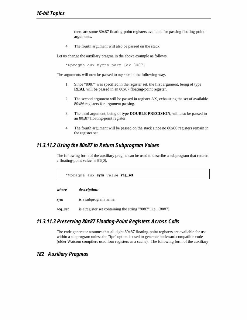
16-bit Topics
there are some 80x87 floating-point registers available for passing floating-pointarguments.
4. The fourth argument will also be passed on the stack.
Let us change the auxiliary pragma in the above example as follows. *$pragma aux myrtn parm [ax 8087]
The arguments will now be passed to myrtn in the following way.
1. Since "8087" was specified in the register set, the first argument, being of typeREAL will be passed in an 80x87 floating-point register.
2. The second argument will be passed in register AX, exhausting the set of available80x86 registers for argument passing.
3. The third argument, being of type DOUBLE PRECISION, will also be passed inan 80x87 floating-point register.
4. The fourth argument will be passed on the stack since no 80x86 registers remain inthe register set.
11.3.11.2 Using the 80x87 to Return Subprogram Values
The following form of the auxiliary pragma can be used to describe a subprogram that returnsa floating-point value in ST(0).
*$pragma aux sym value reg_set
where description:
sym is a subprogram name.
reg_set is a register set containing the string "8087", i.e. [8087].
11.3.11.3 Preserving 80x87 Floating-Point Registers Across Calls
The code generator assumes that all eight 80x87 floating-point registers are available for usewithin a subprogram unless the "fpr" option is used to generate backward compatible code(older Watcom compilers used four registers as a cache). The following form of the auxiliary
182 Auxiliary Pragmas

16-bit Pragmas
pragma specifies that the floating-point registers in the 80x87 cache may be modified by thespecified subprogram.
*$pragma aux sym modify reg_set
where description:
sym is a subprogram name.
reg_set is a register set containing the string "8087", i.e. [8087].
This instructs Watcom F77 to save any local variables that are located in the 80x87 cachebefore calling the specified routine.
Auxiliary Pragmas 183

16-bit Topics
184 Auxiliary Pragmas

32-bit Topics

32-bit Topics
186

12 32-bit Memory Models
12.1 IntroductionThis chapter describes the various 32-bit memory models supported by Watcom F77. Eachmemory model is distinguished by two properties; the code model used to implementsubprogram calls and the data model used to reference data.
12.2 32-bit Code ModelsThere are two code models;
1. the small code model and2. the big code model.
A small code model is one in which all calls to subprograms are made with near calls. In anear call, the destination address is 32 bits and is relative to the segment value in segmentregister CS. Hence, in a small code model, all code comprising your program, includinglibrary subprograms, must be less than 4GB.
A big code model is one in which all calls to subprograms are made with far calls. In a farcall, the destination address is 48 bits (a 16-bit segment value and a 32-bit offset relative tothe segment value). This model allows the size of the code comprising your program toexceed 4GB.
Note: If your program contains less than 4GB of code, you should use a memory modelthat employs the small code model. This will result in smaller and faster code since nearcalls are smaller instructions and are processed faster by the CPU.
32-bit Code Models 187

32-bit Topics
12.3 32-bit Data ModelsThere are two data models;
1. the small data model and2. the big data model.
A small data model is one in which all references to data are made with near pointers. Nearpointers are 32 bits; all data references are made relative to the segment value in segmentregister DS. Hence, in a small data model, all data comprising your program must be less than4GB.
A big data model is one in which all references to data are made with far pointers. Farpointers are 48 bits (a 16-bit segment value and a 32-bit offset relative to the segment value).This removes the 4GB limitation on data size imposed by the small data model. However,when a far pointer is incremented, only the offset is adjusted. Watcom F77 assumes that theoffset portion of a far pointer will not be incremented beyond 4GB. The compiler will assignan object to a new segment if the grouping of data in a segment will cause the object to cross asegment boundary. Implicit in this is the requirement that no individual object exceed 4GB.
Note: If your program contains less than 4GB of data, you should use the small datamodel. This will result in smaller and faster code since references using near pointersproduce fewer instructions.
12.4 Summary of 32-bit Memory ModelsAs previously mentioned, a memory model is a combination of a code model and a datamodel. The following table describes the memory models supported by Watcom F77.
188 Summary of 32-bit Memory Models
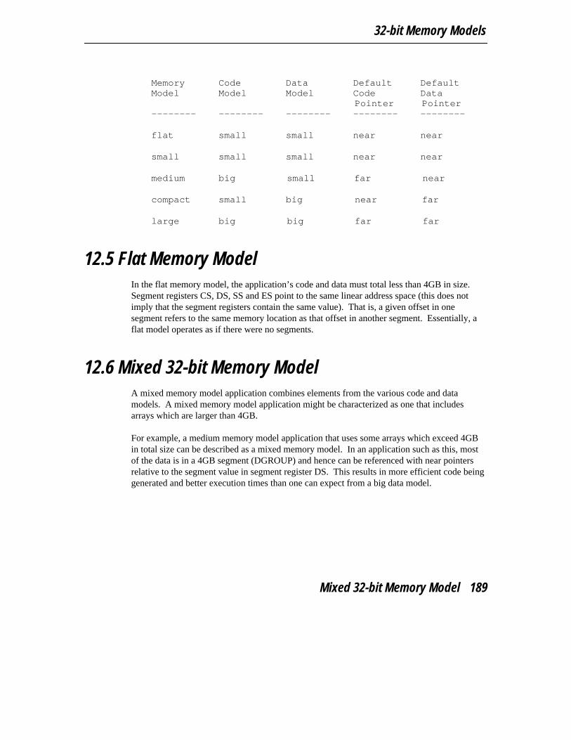
32-bit Memory Models
Memory Code Data Default DefaultModel Model Model Code Data
Pointer Pointer-------- -------- -------- -------- --------
flat small small near near
small small small near near
medium big small far near
compact small big near far
large big big far far
12.5 Flat Memory ModelIn the flat memory model, the application’s code and data must total less than 4GB in size.Segment registers CS, DS, SS and ES point to the same linear address space (this does notimply that the segment registers contain the same value). That is, a given offset in onesegment refers to the same memory location as that offset in another segment. Essentially, aflat model operates as if there were no segments.
12.6 Mixed 32-bit Memory ModelA mixed memory model application combines elements from the various code and datamodels. A mixed memory model application might be characterized as one that includesarrays which are larger than 4GB.
For example, a medium memory model application that uses some arrays which exceed 4GBin total size can be described as a mixed memory model. In an application such as this, mostof the data is in a 4GB segment (DGROUP) and hence can be referenced with near pointersrelative to the segment value in segment register DS. This results in more efficient code beinggenerated and better execution times than one can expect from a big data model.
Mixed 32-bit Memory Model 189

32-bit Topics
12.7 Linking Applications for the Various 32-bitMemory Models
Each memory model requires different run-time and floating-point libraries. Each libraryassumes a particular memory model and should be linked only with modules that have beencompiled with the same memory model. The following table lists the libraries that are to beused to link an application that has been compiled for a particular memory model. Currently,only libraries for the flat/small memory model are provided. The following table lists therun-time libraries used by FORTRAN 77 and the compiler options that cause their use.
1. The "Library" column specified the library name.2. The "Memory model" column indicates the compiler options that specify the
memory model of the library.3. The "Floating-point column" indicates the compiler options that specify the
floating-point model of the library.4. The "Calling convention" column indicates the compiler option that specifies the
calling convention of the library (register-based or stack-based). Library Memory Floating-point Calling
model model convention------- ------ -------------- ----------flib.lib /mf, /ms /fpcflibs.lib /mf, /ms /fpc /scflib7.lib /mf, /ms /fpi, /fpi87flib7s.lib /mf, /ms /fpi, /fpi87 /scclib3r.lib /mf, /ms /fpc, /fpi, /fpi87clib3r.lib /mf, /ms /fpc, /fpi, /fpi87 /scmath387r.lib /mf, /ms /fpi, /fpi87math387s.lib /mf, /ms /fpi, /fpi87 /scmath3r.lib /mf, /ms /fpcmath3s.lib /mf, /ms /fpc /scemu387.lib /mf, /ms /fpinoemu387.lib /mf, /ms /fpi87
12.8 Memory LayoutThe following describes the segment ordering of an application linked by the Watcom Linker.Note that this assumes that the "DOSSEG" linker option has been specified.
1. all "USE16" segments. These segments are present in applications that execute inboth real mode and protected mode. They are first in the segment ordering so thatthe "REALBREAK" option of the "RUNTIME" directive can be used to separatethe real-mode part of the application from the protected-mode part of the
190 Memory Layout

32-bit Memory Models
application. Currently, the "RUNTIME" directive is valid for Phar Lap executablesonly.
2. all segments not belonging to group "DGROUP" with class "CODE"
3. all other segments not belonging to group "DGROUP"
4. all segments belonging to group "DGROUP" with class "BEGDATA"
5. all segments belonging to group "DGROUP" not with class "BEGDATA", "BSS"or "STACK"
6. all segments belonging to group "DGROUP" with class "BSS"
7. all segments belonging to group "DGROUP" with class "STACK"
Segments belonging to class "BSS" contain uninitialized data. Note that this only includesuninitialized data in segments belonging to group "DGROUP". Segments belonging to class"STACK" are used to define the size of the stack used for your application. Segmentsbelonging to the classes "BSS" and "STACK" are last in the segment ordering so thatuninitialized data need not take space in the executable file.
In addition to these special segments, the following conventions are used by Watcom F77.
1. The "CODE" class contains the executable code for your application. In a smallcode model, this consists of the segment "_TEXT". In a big code model, thisconsists of the segments "<subprogram>_TEXT" where <subprogram> is the nameof a subprogram.
2. The "FAR_DATA" class consists of the following:
(a) arrays whose size exceeds the data threshold in large data memorymodels (the data threshold is 256 bytes unless changed using the "dt"compiler option)
(b) equivalenced variables in large data memory models
Memory Layout 191

32-bit Topics
192 Memory Layout

13 32-bit Assembly LanguageConsiderations
13.1 IntroductionThis chapter will deal with the following topics.
1. The memory layout of a program compiled by Watcom F77.
2. The method for passing arguments and returning values.
3. The two methods for passing floating-point arguments and returning floating-pointvalues.
One method is used when one of the Watcom F77 "fpi", "fpi87" or "fpi287" optionsis specified for the generation of in-line 80x87 instructions. When the "fpi" optionis specified, an 80x87 emulator is included from a math library if the applicationincludes floating-point operations. When the "fpi87" or "fpi287" option is usedexclusively, the 80x87 emulator will not be included.
The other method is used when the Watcom F77 "fpc" option is specified. In thiscase, the compiler generates calls to floating-point support routines in the alternatemath libraries.
An understanding of the Intel 80x86 architecture is assumed.
13.2 Calling ConventionsThe following sections describe the method used by Watcom F77 to pass arguments.
The FORTRAN 77 language specifically requires that arguments be passed by reference.This means that instead of passing the value of an argument, its address is passed. This allowsa called subprogram to modify the value of the actual arguments. The following illustrates themethod used to pass arguments.
Calling Conventions 193
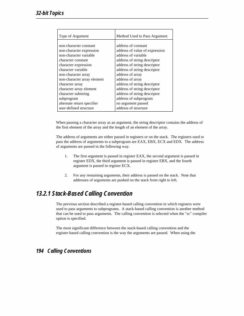
32-bit Topics
Type of Argument Method Used to Pass Argument
non-character constant address of constantnon-character expression address of value of expressionnon-character variable address of variablecharacter constant address of string descriptorcharacter expression address of string descriptorcharacter variable address of string descriptornon-character array address of arraynon-character array element address of arraycharacter array address of string descriptorcharacter array element address of string descriptorcharacter substring address of string descriptorsubprogram address of subprogramalternate return specifier no argument passeduser-defined structure address of structure
When passing a character array as an argument, the string descriptor contains the address ofthe first element of the array and the length of an element of the array.
The address of arguments are either passed in registers or on the stack. The registers used topass the address of arguments to a subprogram are EAX, EBX, ECX and EDX. The addressof arguments are passed in the following way.
1. The first argument is passed in register EAX, the second argument is passed inregister EDX, the third argument is passed in register EBX, and the fourthargument is passed in register ECX.
2. For any remaining arguments, their address is passed on the stack. Note thataddresses of arguments are pushed on the stack from right to left.
13.2.1 Stack-Based Calling Convention
The previous section described a register-based calling convention in which registers wereused to pass arguments to subprograms. A stack-based calling convention is another methodthat can be used to pass arguments. The calling convention is selected when the "sc" compileroption is specified.
The most significant difference between the stack-based calling convention and theregister-based calling convention is the way the arguments are passed. When using the
194 Calling Conventions

32-bit Assembly Language Considerations
stack-based calling conventions, no registers are used to pass arguments. Instead, allarguments are passed on the stack.
13.2.2 Processing Function Return Values with no 80x87
The way in which function values are returned is also dependent on the data type of thefunction. The following describes the method used to return function values.
1. LOGICAL*1 values are returned in register AL.
2. LOGICAL*4 values are returned in register EAX.
3. INTEGER*1 values are returned in register AL.
4. INTEGER*2 values are returned in register AX.
5. INTEGER*4 values are returned in register EAX.
6. REAL*4 values are returned in register EAX.
7. REAL*8 values are returned in registers EDX:EAX.
8. For COMPLEX*8 functions, space is allocated on the stack by the caller for thereturn value. Register ESI is set to point to the destination of the result. The calledfunction places the result at the location pointed to by register ESI.
9. For COMPLEX*16 functions, space is allocated on the stack by the caller for thereturn value. Register ESI is set to point to the destination of the result. The calledfunction places the result at the location pointed to by register ESI.
10. For CHARACTER functions, an additional argument is passed. This argument isthe address of the string descriptor for the result. Note that the address of the stringdescriptor can be passed in any of the registers that are used to pass actualarguments.
11. For functions that return a user-defined structure, space is allocated on the stack bythe caller for the return value. Register ESI is set to point to the destination of theresult. The called function places the result at the location pointed to by registerESI. Note that a structure of size 1, 2 or 4 bytes is returned in register AL, AX orEAX respectively.
Calling Conventions 195

32-bit Topics
Note: The way in which a function returns its value does not change when the stack-basedcalling convention is used.
13.2.3 Processing Function Return Values Using an 80x87
The following describes the method used to return function values when your application iscompiled using the "fpi87" or "fpi" option.
1. For REAL*4 functions, the result is returned in floating-point register ST(0).2. For REAL*8 functions, the result is returned in floating-point register ST(0).3. All other function values are returned in the way described in the previous section.
Note: When the stack-based calling convention is used, floating-point values are notreturned using the 80x87. REAL*4 values are returned in register EAX. REAL*8 valuesare returned in registers EDX:EAX.
13.2.4 Processing Alternate Returns
Alternate returns are processed by the caller and are only allowed in subroutines. The calledsubroutine places the value specified in the RETURN statement in register EAX. Note thatthe value returned in register EAX is ignored if there are no alternate return specifiers in theactual argument list.
Note: The way in which a alternate returns are processed does not change when thestack-based calling convention is used.
13.2.5 Alternate Method of Passing Character Arguments
As previously described, character arguments are passed using string descriptors. Recall thata string descriptor contains a pointer to the actual character data and the length of thecharacter data. When passing character data, both a pointer and length are required by thesubprogram being called. When using a string descriptor, this information can be passedusing a single argument, namely the pointer to the string descriptor.
196 Calling Conventions

32-bit Assembly Language Considerations
An alternate method of passing character arguments is also supported and is selected when the"nodescriptor" option is specified. In this method, the pointer to the character data and thelength of the character data are passed as two separate arguments. The character argumentlengths are appended to the end of the actual argument list.
Let us consider the following example. INTEGER A, CCHARACTER B, DCALL SUB( A, B, C, D )
In the above example, the first argument is of type INTEGER, the second argument is of typeCHARACTER, the third argument is of type INTEGER, and the fourth argument is of typeCHARACTER. If the character arguments were passed by descriptor, the argument list wouldresemble the following.
1. The first argument would be the address of A.2. The second argument would be the address of the string descriptor for B.3. The third argument would be the address of C.4. The fourth argument would be the address of the string descriptor for D.
If we specified the "nodescriptor" option, the argument list would be as follows.
1. The first argument would be the address of A.2. The second argument would be the address of the character data for B.3. The third argument would be the address of C.4. The fourth argument would be the address of the character data for D.5. A hidden argument for the length of B would be the fifth argument.6. A hidden argument for the length of D would be the sixth argument.
Note that the arguments corresponding to the length of the character arguments are passed asINTEGER*4 arguments.
13.2.5.1 Character Functions
By default, when a character function is called, a hidden argument is passed at the end of theactual argument list. This hidden argument is a pointer to the string descriptor used for thereturn value of the character function. When the alternate method of passing characterarguments is specified by using the "nodescriptor" option, the string descriptor for the returnvalue is passed to the function as two hidden arguments, similar to the way characterarguments were passed. However the two hidden arguments for the return value of thecharacter function are placed at the beginning of the actual argument list. The first argumentis the the pointer to the storage immediately followed by the size of the storage.
Calling Conventions 197

32-bit Topics
13.3 Memory LayoutThe following describes the segment ordering of an application linked by the Watcom Linker.Note that this assumes that the "DOSSEG" linker option has been specified.
1. all "USE16" segments. These segments are present in applications that execute inboth real mode and protected mode. They are first in the segment ordering so thatthe "REALBREAK" option of the "RUNTIME" directive can be used to separatethe real-mode part of the application from the protected-mode part of theapplication. Currently, the "RUNTIME" directive is valid for Phar Lap executablesonly.
2. all segments not belonging to group "DGROUP" with class "CODE"
3. all other segments not belonging to group "DGROUP"
4. all segments belonging to group "DGROUP" with class "BEGDATA"
5. all segments belonging to group "DGROUP" not with class "BEGDATA", "BSS"or "STACK"
6. all segments belonging to group "DGROUP" with class "BSS"
7. all segments belonging to group "DGROUP" with class "STACK"
Segments belonging to class "BSS" contain uninitialized data. Note that this only includesuninitialized data in segments belonging to group "DGROUP". Segments belonging to class"STACK" are used to define the size of the stack used for your application. Segmentsbelonging to the classes "BSS" and "STACK" are last in the segment ordering so thatuninitialized data need not take space in the executable file.
In addition to these special segments, the following conventions are used by Watcom F77.
1. The "CODE" class contains the executable code for your application. In a smallcode model, this consists of the segment "_TEXT". In a big code model, thisconsists of the segments "<subprogram>_TEXT" where <subprogram> is the nameof a subprogram.
2. The "FAR_DATA" class consists of the following:
198 Memory Layout

32-bit Assembly Language Considerations
(a) arrays whose size exceeds the data threshold in large data memorymodels (the data threshold is 256 bytes unless changed using the "dt"compiler option)
(b) equivalenced variables in large data memory models
13.4 Writing Assembly Language SubprogramsWhen writing assembly language subprograms, use the following guidelines.
1. All used registers must be saved on entry and restored on exit except those used topass arguments and return values. Note that segment registers only have to besaved and restored if you are compiling your application with the "sr" option.
2. The direction flag must be clear before returning to the caller.
3. In a small code model, any segment containing executable code must belong to thesegment "_TEXT" and the class "CODE". The segment "_TEXT" must have a"combine" type of "PUBLIC". On entry, register CS contains the segment addressof the segment "_TEXT". In a big code model there is no restriction on the namingof segments which contain executable code.
4. In a small data model, segment register DS contains the segment address of thedefault data segment (group "DGROUP"). In a big data model, segment registerSS (not DS) contains the segment address of the default data segment (group"DGROUP").
5. When writing assembly language subprograms for the small code model, you mustdeclare them as "near". If you wish to write assembly language subprograms forthe big code model, you must declare them as "far".
6. Use the ".8087" pseudo-op so that floating-point constants are in the correct format.
7. The called subprogram must remove arguments that were passed on the stack in the"ret" instruction.
8. In general, when naming segments for your code or data, you should follow theconventions described in the section entitled "Memory Layout" in this chapter.
Consider the following example.
Writing Assembly Language Subprograms 199

32-bit Topics
INTEGER HRS, MINS, SECS, HSECSCALL GETTIM( HRS, MINS, SECS, HSECS )PRINT 100, HRS, MINS, SECS, HSECS
100 FORMAT( 1X,I2.2,’:’,I2.2,’:’,I2.2,’.’,I2.2 )END
GETTIM is an assembly language subroutine that gets the current time. It requires fourinteger arguments. The arguments are passed by reference so that the subroutine can returnthe hour, minute, seconds and hundredths of a second for the current time. These argumentswill be passed to GETTIM in the following way.
1. The address of the first argument will be passed in register EAX.2. The address of the second argument will be passed in register EDX.3. The address of the third argument will be passed in register EBX.4. The address of the fourth argument will be passed in register ECX.
The following is an assembly language subprogram which implements GETTIM.
Small or Flat Memory Model (small code, small data) TEXT segment byte public ’CODE’
assume CS: TEXTpublic GETTIM
GETTIM proc nearpush EAX ; save registers modified bypush ECX ; ... DOS function callpush EDX ; ...mov AH,2ch ; set DOS "get time" functionint 21h ; issue DOS function callmovzx EAX,DH ; get secondsmov [EBX],EAX ; return secondspop EBX ; get address of minutesmovzx EAX,CL ; get minutesmov [EBX],EAX ; return minutespop EBX ; get address of ticksmovzx EAX,DL ; get ticksmov [EBX],EAX ; return tickspop EBX ; get address of hoursmovzx EAX,CH ; get hoursmov [EBX],EAX ; return hoursret ; return
GETTIM endpTEXT ends
end
200 Writing Assembly Language Subprograms
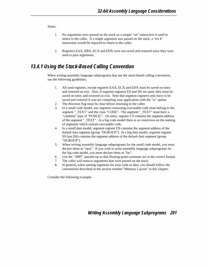
32-bit Assembly Language Considerations
Notes:
1. No arguments were passed on the stack so a simple "ret" instruction is used toreturn to the caller. If a single argument was passed on the stack, a "ret 4"instruction would be required to return to the caller.
2. Registers EAX, EBX, ECX and EDX were not saved and restored since they wereused to pass arguments.
13.4.1 Using the Stack-Based Calling Convention
When writing assembly language subprograms that use the stack-based calling convention,use the following guidelines.
1. All used registers, except registers EAX, ECX and EDX must be saved on entryand restored on exit. Also, if segment registers ES and DS are used, they must besaved on entry and restored on exit. Note that segment registers only have to besaved and restored if you are compiling your application with the "sr" option.
2. The direction flag must be clear before returning to the caller.3. In a small code model, any segment containing executable code must belong to the
segment "_TEXT" and the class "CODE". The segment "_TEXT" must have a"combine" type of "PUBLIC". On entry, register CS contains the segment addressof the segment "_TEXT". In a big code model there is no restriction on the namingof segments which contain executable code.
4. In a small data model, segment register DS contains the segment address of thedefault data segment (group "DGROUP"). In a big data model, segment registerSS (not DS) contains the segment address of the default data segment (group"DGROUP").
5. When writing assembly language subprograms for the small code model, you mustdeclare them as "near". If you wish to write assembly language subprograms forthe big code model, you must declare them as "far".
6. Use the ".8087" pseudo-op so that floating-point constants are in the correct format.7. The caller will remove arguments that were passed on the stack.8. In general, when naming segments for your code or data, you should follow the
conventions described in the section entitled "Memory Layout" in this chapter.
Consider the following example.
Writing Assembly Language Subprograms 201
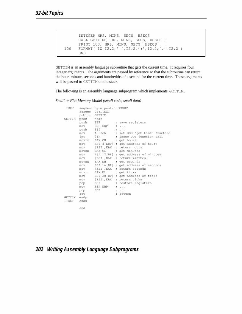
32-bit Topics
INTEGER HRS, MINS, SECS, HSECSCALL GETTIM( HRS, MINS, SECS, HSECS )PRINT 100, HRS, MINS, SECS, HSECS
100 FORMAT( 1X,I2.2,’:’,I2.2,’:’,I2.2,’.’,I2.2 )END
GETTIM is an assembly language subroutine that gets the current time. It requires fourinteger arguments. The arguments are passed by reference so that the subroutine can returnthe hour, minute, seconds and hundredths of a second for the current time. These argumentswill be passed to GETTIM on the stack.
The following is an assembly language subprogram which implements GETTIM.
Small or Flat Memory Model (small code, small data) TEXT segment byte public ’CODE’
assume CS: TEXTpublic GETTIM
GETTIM proc nearpush EBP ; save registersmov EBP,ESP ; ...push ESI ; ...mov AH,2ch ; set DOS "get time" functionint 21h ; issue DOS function callmovzx EAX,CH ; get hoursmov ESI,8[EBP] ; get address of hoursmov [ESI],EAX ; return hoursmovzx EAX,CL ; get minutesmov ESI,12[BP] ; get address of minutesmov [ESI],EAX ; return minutesmovzx EAX,DH ; get secondsmov ESI,16[BP] ; get address of secondsmov [ESI],EAX ; return secondsmovzx EAX,DL ; get ticksmov ESI,20[BP] ; get address of ticksmov [ESI],EAX ; return tickspop ESI ; restore registersmov ESP,EBP ; ...pop EBP ; ...ret ; return
GETTIM endpTEXT ends
end
202 Writing Assembly Language Subprograms

32-bit Assembly Language Considerations
Notes:
1. The four arguments that were passed on the stack will be removed by the caller.
2. Registers ESI and EBP were saved and restored since they were used in GETTIM.
Let us look at the stack upon entry to GETTIM. Offset
0 +----------------+ <- ESP points here| return address |
4 +----------------+| argument #1 |
8 +----------------+| argument #2 |
12 +----------------+| argument #3 |
16 +----------------+| argument #4 |
20 +----------------+| |
Notes:
1. The top element of the stack is a the 32-bit return address. The first argument is atoffset 4 from the top of the stack, the second argument at offset 8, the thirdargument at offset 12, and the fourth argument at offset 16.
Register EBP is normally used to address arguments on the stack. Upon entry to thesubroutine, registers that are modified (except registers EAX, ECX and EDX) are saved andregister EBP is set to point to the stack. After performing this prologue sequence, the stacklooks like this.
Writing Assembly Language Subprograms 203

32-bit Topics
Offset from EBP
-4 +----------------+ <- ESP point here| saved ESI |
0 +----------------+ <- EBP point here| saved EBP |
4 +----------------+| return address |
8 +----------------+| argument #1 |
12 +----------------+| argument #2 |
16 +----------------+| argument #3 |
20 +----------------+| argument #4 |
24 +----------------+| |
As the above diagram shows, the first argument is at offset 8 from register EBP, the secondargument is at offset 12, the third argument is at offset 16, and the fourth argument is at offset20.
13.4.2 Returning Values from Assembly Language Functions
The following illustrates the way function values are to be returned from assembly languagefunctions.
Note: The way in which a function returns its value does not change when the stack-basedcalling convention is used.
1. A LOGICAL*1 function. TEXT segment byte public ’CODE’
assume CS: TEXTpublic L1
L1 proc nearmov AL,1ret
L1 endpTEXT ends
end
2. A LOGICAL*4 function.
204 Writing Assembly Language Subprograms

32-bit Assembly Language Considerations
TEXT segment byte public ’CODE’
assume CS: TEXTpublic L4
L4 proc nearmov EAX,0ret
L4 endpTEXT ends
end
3. An INTEGER*1 function. TEXT segment byte public ’CODE’
assume CS: TEXTpublic I1
I1 proc nearmov AL,73ret
I1 endpTEXT ends
end
4. An INTEGER*2 function. TEXT segment byte public ’CODE’
assume CS: TEXTpublic I2
I2 proc nearmov AX,7143ret
I2 endpTEXT ends
end
5. An INTEGER*4 function. TEXT segment byte public ’CODE’
assume CS: TEXTpublic I4
I4 proc nearmov EAX,383ret
I4 endpTEXT ends
end
6. A REAL*4 function.
Writing Assembly Language Subprograms 205

32-bit Topics
.8087
DGROUP group R4 DATA
TEXT segment byte public ’CODE’assume CS: TEXTassume DS:DGROUPpublic R4
R4 proc nearmov EAX,dword ptr R4Valret
R4 endpTEXT ends
R4 DATA segment byte public ’DATA’R4Val dd 1314.3R4 DATA ends
end
7. A REAL*8 function. .8087
DGROUP group R8 DATA
TEXT segment byte public ’CODE’assume CS: TEXTassume DS:DGROUPpublic R8
R8 proc nearmov EAX,dword ptr R8Valmov EDX,dword ptr R8Val+4ret
R8 endpTEXT ends
R8 DATA segment byte public ’DATA’R8Val dq 103.3R8 DATA ends
end
8. A COMPLEX*8 function. .8087
DGROUP group C8 DATA
TEXT segment byte public ’CODE’assume CS: TEXTassume DS:DGROUPpublic C8
206 Writing Assembly Language Subprograms

32-bit Assembly Language Considerations
C8 proc nearpush EAXmov EAX,C8Valmov [ESI],EAXmov EAX,C8Val+4mov 4[ESI],EAXpop EAXret
C8 endpTEXT ends
C8 DATA segment byte public ’DATA’C8Val dd 2.2
dd 2.2C8 DATA ends
end
9. A COMPLEX*16 function. .8087
DGROUP group C16 DATA
TEXT segment byte public ’CODE’assume CS: TEXTassume DS:DGROUPpublic C16
C16 proc nearpush EAXmov EAX,dword ptr C16Valmov [ESI],EAXmov EAX,dword ptr C16Val+4mov 4[ESI],EAXmov EAX,dword ptr C16Val+8mov 8[ESI],EAXmov EAX,dword ptr C16Val+12mov 12[ESI],EAXpop EAXret
C16 endpTEXT ends
C16 DATA segment byte public ’DATA’C16Val dq 3.3
dq 3.3C16 DATA ends
end
10. A CHARACTER function. TEXT segment byte public ’CODE’
assume CS: TEXTpublic CHR
CHR proc nearpush EAX
Writing Assembly Language Subprograms 207
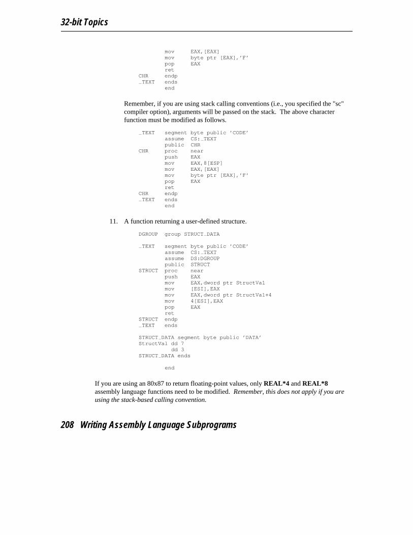
32-bit Topics
mov EAX,[EAX]mov byte ptr [EAX],’F’pop EAXret
CHR endpTEXT ends
end
Remember, if you are using stack calling conventions (i.e., you specified the "sc"compiler option), arguments will be passed on the stack. The above characterfunction must be modified as follows.
TEXT segment byte public ’CODE’
assume CS: TEXTpublic CHR
CHR proc nearpush EAXmov EAX,8[ESP]mov EAX,[EAX]mov byte ptr [EAX],’F’pop EAXret
CHR endpTEXT ends
end
11. A function returning a user-defined structure. DGROUP group STRUCT DATA
TEXT segment byte public ’CODE’assume CS: TEXTassume DS:DGROUPpublic STRUCT
STRUCT proc nearpush EAXmov EAX,dword ptr StructValmov [ESI],EAXmov EAX,dword ptr StructVal+4mov 4[ESI],EAXpop EAXret
STRUCT endpTEXT ends
STRUCT DATA segment byte public ’DATA’StructVal dd 7
dd 3STRUCT DATA ends
end
If you are using an 80x87 to return floating-point values, only REAL*4 and REAL*8assembly language functions need to be modified. Remember, this does not apply if you areusing the stack-based calling convention.
208 Writing Assembly Language Subprograms
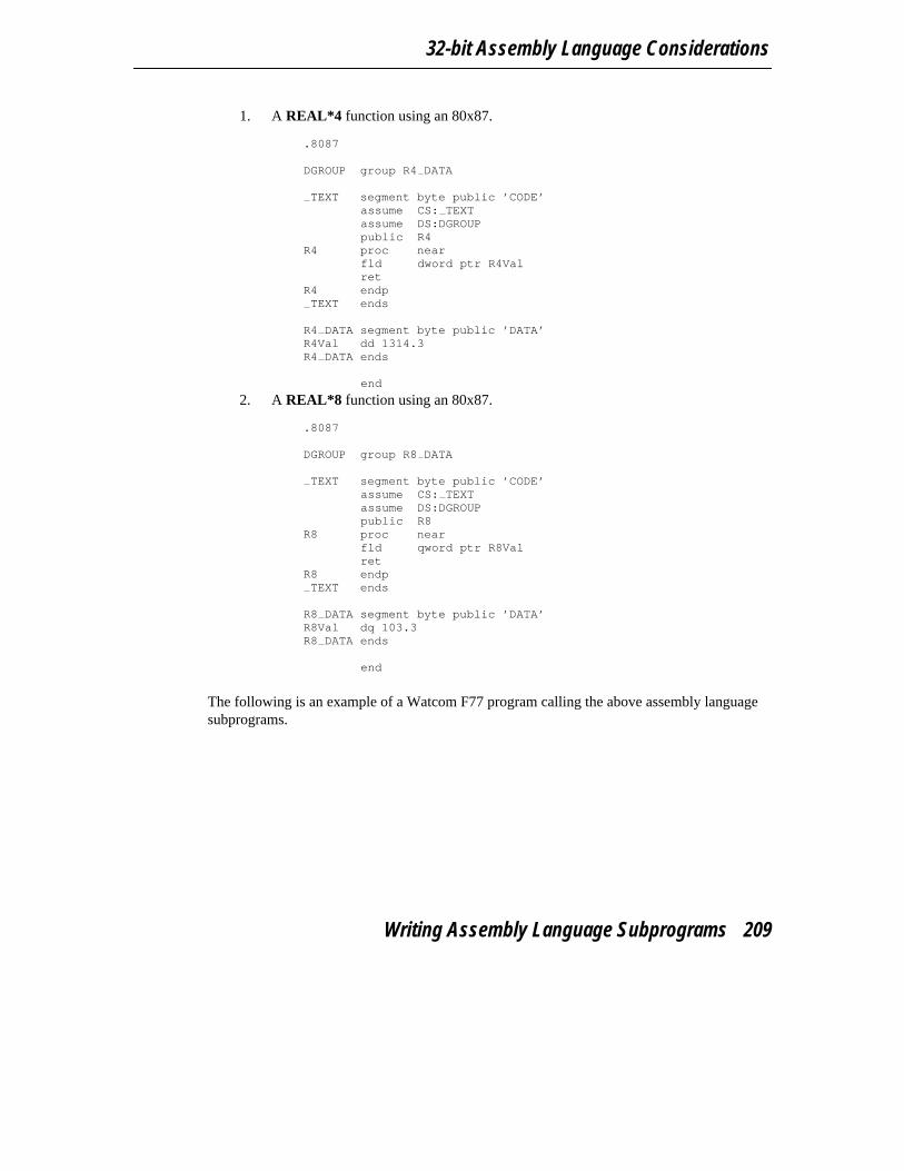
32-bit Assembly Language Considerations
1. A REAL*4 function using an 80x87. .8087
DGROUP group R4 DATA
TEXT segment byte public ’CODE’assume CS: TEXTassume DS:DGROUPpublic R4
R4 proc nearfld dword ptr R4Valret
R4 endpTEXT ends
R4 DATA segment byte public ’DATA’R4Val dd 1314.3R4 DATA ends
end
2. A REAL*8 function using an 80x87. .8087
DGROUP group R8 DATA
TEXT segment byte public ’CODE’assume CS: TEXTassume DS:DGROUPpublic R8
R8 proc nearfld qword ptr R8Valret
R8 endpTEXT ends
R8 DATA segment byte public ’DATA’R8Val dq 103.3R8 DATA ends
end
The following is an example of a Watcom F77 program calling the above assembly languagesubprograms.
Writing Assembly Language Subprograms 209

32-bit Topics
logical l1*1, l4*4integer i1*1, i2*2, i4*4real r4*4, r8*8complex c8*8, c16*16character chrstructure /coord/
integer x, yend structurerecord /coord/ structprint *, l1()print *, l4()print *, i1()print *, i2()print *, i4()print *, r4()print *, r8()print *, c8()print *, c16()print *, chr()print *, struct()end
210 Writing Assembly Language Subprograms
14 32-bit Pragmas
14.1 IntroductionA pragma is a compiler directive that provides the following capabilities.
• Pragmas can be used to direct the Watcom F77 code generator to emit specializedsequences of code for calling functions which use argument passing and value returntechniques that differ from the default used by Watcom F77.
• Pragmas can be used to describe attributes of functions (such as side effects) that arenot possible at the FORTRAN 77 language level. The code generator can use thisinformation to generate more efficient code.
• Any sequence of in-line machine language instructions, including DOS and BIOSfunction calls, can be generated in the object code.
Pragmas are specified in the source file using the pragma directive. The following notation isused to describe the syntax of pragmas.
keywords A keyword is shown in a mono-spaced courier font.
program-item A program-item is shown in a roman bold-italics font. A program-item is asymbol name or numeric value supplied by the programmer.
punctuation A punctuation character shown in a mono-spaced courier font must beentered as is.
A punctuation character shown in a roman bold-italics font is used to describesyntax. The following syntactical notation is used.
[abc] The item abc is optional.
{abc} The item abc may be repeated zero or more times.
a|b|c One of a, b or c may be specified.
Introduction 211
32-bit Topics
a ::= b The item a is defined in terms of b.
(a) Item a is evaluated first.
The following classes of pragmas are supported.
• pragmas that specify default libraries
• pragmas that provide auxiliary information used for code generation
14.2 Using Pragmas to Specify Default LibrariesDefault libraries are specified in special object module records. Library names are extractedfrom these special records by the Watcom Linker. When unresolved references remain afterprocessing all object modules specified in linker "FILE" directives, these default libraries aresearched after all libraries specified in linker "LIBRARY" directives have been searched.
By default, that is if no library pragma is specified, the Watcom F77 compiler generates, inthe object file defining the main program, default libraries corresponding to the memorymodel and floating-point model used to compile the file. For example, if you have compiledthe source file containing the main program for the flat memory model and the floating-pointcalls floating-point model, the library "flib" will be placed in the object file.
If you wish to add your own default libraries to this list, you can do so with a library pragma.Consider the following example.
*$pragma library mylib
The name "mylib" will be added to the list of default libraries specified in the object file.
If you wish to specify more than one library in a library pragma you must separate them withspaces as in the following example.
*$pragma library mylib \watcom\lib286\dos\graph.lib*$pragma library mylib \watcom\lib386\dos\graph.lib
If no libraries are specified as in the following example, *$pragma library
the run-time libraries corresponding to the memory and floating-point models used to compilethe file will be generated.
212 Using Pragmas to Specify Default Libraries
32-bit Pragmas
14.3 Auxiliary PragmasThe following sections describe the capabilities provided by auxiliary pragmas.
The backslash character (’\’) is used to continue a pragma on the next line. Text following thebackslash character is ignored. The line continuing the pragma must start with a commentcharacter (’c’, ’C’ or ’*’).
14.3.1 Specifying Symbol Attributes
Auxiliary pragmas are used to describe attributes that affect code generation. Initially, thecompiler defines a default set of attributes. Each auxiliary pragma refers to one of thefollowing.
1. a symbol (such as a variable or function)2. the default set of attributes defined by the compiler
When an auxiliary pragma refers to a particular symbol, a copy of the current set of defaultattributes is made and merged with the attributes specified in the auxiliary pragma. Theresulting attributes are assigned to the specified symbol and can only be changed by anotherauxiliary pragma that refers to the same symbol.
When "default" is specified instead of a symbol name, the attributes specified by the auxiliarypragma change the default set of attributes. The resulting attributes are used by all symbolsthat have not been specifically referenced by a previous auxiliary pragma.
Note that all auxiliary pragmas are processed before code generation begins. Consider thefollowing example.
code in which symbol x is referenced*$pragma aux y <attrs 1>code in which symbol y is referencedcode in which symbol z is referenced*$pragma aux default <attrs 2>*$pragma aux x <attrs 3>
Auxiliary attributes are assigned to x, y and z in the following way.
1. Symbol x is assigned the initial default attributes merged with the attributesspecified by <attrs 2> and <attrs 3>.
Auxiliary Pragmas 213
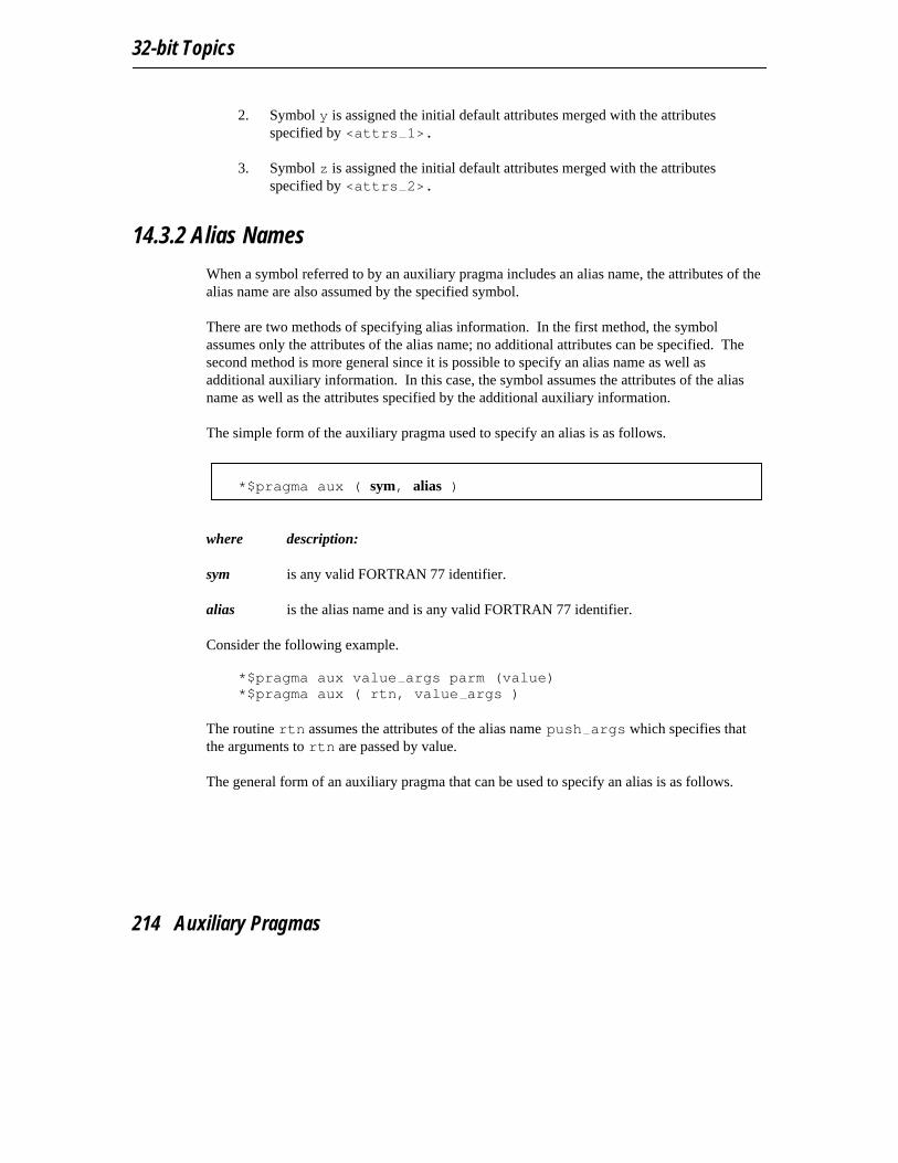
32-bit Topics
2. Symbol y is assigned the initial default attributes merged with the attributesspecified by <attrs 1>.
3. Symbol z is assigned the initial default attributes merged with the attributesspecified by <attrs 2>.
14.3.2 Alias Names
When a symbol referred to by an auxiliary pragma includes an alias name, the attributes of thealias name are also assumed by the specified symbol.
There are two methods of specifying alias information. In the first method, the symbolassumes only the attributes of the alias name; no additional attributes can be specified. Thesecond method is more general since it is possible to specify an alias name as well asadditional auxiliary information. In this case, the symbol assumes the attributes of the aliasname as well as the attributes specified by the additional auxiliary information.
The simple form of the auxiliary pragma used to specify an alias is as follows.
*$pragma aux ( sym, alias )
where description:
sym is any valid FORTRAN 77 identifier.
alias is the alias name and is any valid FORTRAN 77 identifier.
Consider the following example. *$pragma aux value args parm (value) *$pragma aux ( rtn, value args )
The routine rtn assumes the attributes of the alias name push args which specifies thatthe arguments to rtn are passed by value.
The general form of an auxiliary pragma that can be used to specify an alias is as follows.
214 Auxiliary Pragmas

32-bit Pragmas
*$pragma aux ( alias ) sym aux_attrs
where description:
alias is the alias name and is any valid FORTRAN 77 identifier.
sym is any valid FORTRAN 77 identifier.
aux_attrs are attributes that can be specified with the auxiliary pragma.
Consider the following example. *$pragma aux WC "* " parm (value)*$pragma aux (WC) rtn1*$pragma aux (WC) rtn2*$pragma aux (WC) rtn3
The routines rtn1, rtn2 and rtn3 assume the same attributes as the alias name WC whichdefines the calling convention used by the Watcom C compiler. Whenever calls are made tortn1, rtn2 and rtn3, the Watcom C calling convention will be used. Note thatarguments must be passed by value. By default, Watcom F77 passes arguments by reference.
Note that if the attributes of WC change, only one pragma needs to be changed. If we had notused an alias name and specified the attributes in each of the three pragmas for rtn1, rtn2and rtn3, we would have to change all three pragmas. This approach also reduces theamount of memory required by the compiler to process the source file.
WARNING! The alias name WC is just another symbol. If WC appeared in your sourcecode, it would assume the attributes specified in the pragma for WC.
14.3.3 Predefined Aliases
A number of symbols are predefined by the compiler with a set of attributes that describe aparticular calling convention. These symbols can be used as aliases. The following is a list ofthese symbols.
Auxiliary Pragmas 215
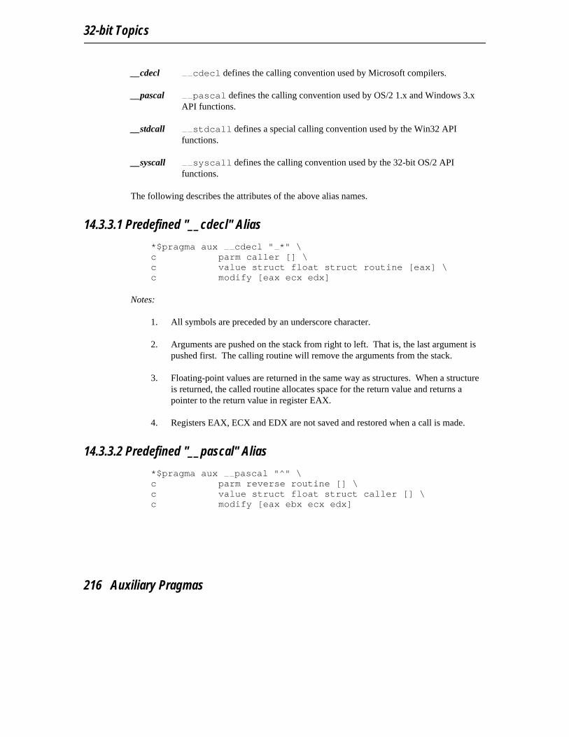
32-bit Topics
__cdecl cdecl defines the calling convention used by Microsoft compilers.
__pascal pascal defines the calling convention used by OS/2 1.x and Windows 3.xAPI functions.
__stdcall stdcall defines a special calling convention used by the Win32 APIfunctions.
__syscall syscall defines the calling convention used by the 32-bit OS/2 APIfunctions.
The following describes the attributes of the above alias names.
14.3.3.1 Predefined "__cdecl" Alias *$pragma aux cdecl " *" \c parm caller [] \c value struct float struct routine [eax] \c modify [eax ecx edx]
Notes:
1. All symbols are preceded by an underscore character.
2. Arguments are pushed on the stack from right to left. That is, the last argument ispushed first. The calling routine will remove the arguments from the stack.
3. Floating-point values are returned in the same way as structures. When a structureis returned, the called routine allocates space for the return value and returns apointer to the return value in register EAX.
4. Registers EAX, ECX and EDX are not saved and restored when a call is made.
14.3.3.2 Predefined "__pascal" Alias *$pragma aux pascal "^" \c parm reverse routine [] \c value struct float struct caller [] \c modify [eax ebx ecx edx]
216 Auxiliary Pragmas
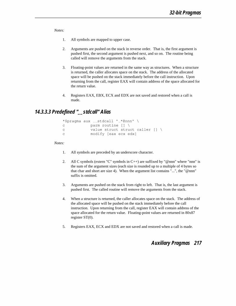
32-bit Pragmas
Notes:
1. All symbols are mapped to upper case.
2. Arguments are pushed on the stack in reverse order. That is, the first argument ispushed first, the second argument is pushed next, and so on. The routine beingcalled will remove the arguments from the stack.
3. Floating-point values are returned in the same way as structures. When a structureis returned, the caller allocates space on the stack. The address of the allocatedspace will be pushed on the stack immediately before the call instruction. Uponreturning from the call, register EAX will contain address of the space allocated forthe return value.
4. Registers EAX, EBX, ECX and EDX are not saved and restored when a call ismade.
14.3.3.3 Predefined "__stdcall" Alias *$pragma aux stdcall " *@nnn" \c parm routine [] \c value struct struct caller [] \c modify [eax ecx edx]
Notes:
1. All symbols are preceded by an underscore character.
2. All C symbols (extern "C" symbols in C++) are suffixed by "@nnn" where "nnn" isthe sum of the argument sizes (each size is rounded up to a multiple of 4 bytes sothat char and short are size 4). When the argument list contains "...", the "@nnn"suffix is omitted.
3. Arguments are pushed on the stack from right to left. That is, the last argument ispushed first. The called routine will remove the arguments from the stack.
4. When a structure is returned, the caller allocates space on the stack. The address ofthe allocated space will be pushed on the stack immediately before the callinstruction. Upon returning from the call, register EAX will contain address of thespace allocated for the return value. Floating-point values are returned in 80x87register ST(0).
5. Registers EAX, ECX and EDX are not saved and restored when a call is made.
Auxiliary Pragmas 217

32-bit Topics
14.3.3.4 Predefined "__syscall" Alias *$pragma aux syscall "*" \c parm caller [] \c value struct struct caller [] \c modify [eax ecx edx]
Notes:
1. Symbols names are not modified, that is, they are not adorned with leading ortrailing underscores.
2. Arguments are pushed on the stack from right to left. That is, the last argument ispushed first. The calling routine will remove the arguments from the stack.
3. When a structure is returned, the caller allocates space on the stack. The address ofthe allocated space will be pushed on the stack immediately before the callinstruction. Upon returning from the call, register EAX will contain address of thespace allocated for the return value. Floating-point values are returned in 80x87register ST(0).
4. Registers EAX, ECX and EDX are not saved and restored when a call is made.
14.3.4 Alternate Names for Symbols
The following form of the auxiliary pragma can be used to describe the mapping of a symbolfrom its source form to its object form.
*$pragma aux sym obj_name
where description:
sym is any valid FORTRAN 77 identifier.
obj_name is any character string enclosed in double quotes.
When specifying obj name, the asterisk character (’*’) has a special meaning; it is aplaceholder for the upper case version of sym.
In the following example, the name "myrtn" will be replaced by "MYRTN_" in the object file.
218 Auxiliary Pragmas
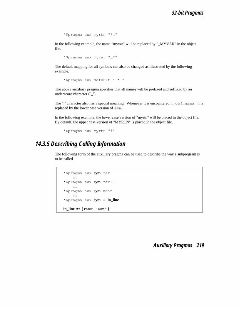
32-bit Pragmas
*$pragma aux myrtn "* "
In the following example, the name "myvar" will be replaced by "_MYVAR" in the objectfile.
*$pragma aux myvar " *"
The default mapping for all symbols can also be changed as illustrated by the followingexample.
*$pragma aux default " * "
The above auxiliary pragma specifies that all names will be prefixed and suffixed by anunderscore character (’_’).
The ’!’ character also has a special meaning. Whenever it is encountered in obj name, it isreplaced by the lower case version of sym.
In the following example, the lower case version of "myrtn" will be placed in the object file.By default, the upper case version of "MYRTN" is placed in the object file.
*$pragma aux myrtn "!"
14.3.5 Describing Calling Information
The following form of the auxiliary pragma can be used to describe the way a subprogram isto be called.
*$pragma aux sym faror
*$pragma aux sym far16or
*$pragma aux sym nearor
*$pragma aux sym = in_line
in_line ::= { const | "asm" }
Auxiliary Pragmas 219
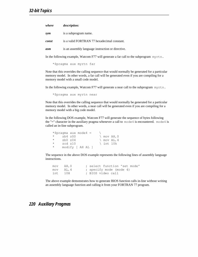
32-bit Topics
where description:
sym is a subprogram name.
const is a valid FORTRAN 77 hexadecimal constant.
asm is an assembly language instruction or directive.
In the following example, Watcom F77 will generate a far call to the subprogram myrtn. *$pragma aux myrtn far
Note that this overrides the calling sequence that would normally be generated for a particularmemory model. In other words, a far call will be generated even if you are compiling for amemory model with a small code model.
In the following example, Watcom F77 will generate a near call to the subprogram myrtn. *$pragma aux myrtn near
Note that this overrides the calling sequence that would normally be generated for a particularmemory model. In other words, a near call will be generated even if you are compiling for amemory model with a big code model.
In the following DOS example, Watcom F77 will generate the sequence of bytes followingthe "=" character in the auxiliary pragma whenever a call to mode4 is encountered. mode4 iscalled an in-line subprogram.
*$pragma aux mode4 = \* zb4 z00 \ mov AH,0* zb0 z04 \ mov AL,4* zcd z10 \ int 10h* modify [ AH AL ]
The sequence in the above DOS example represents the following lines of assembly languageinstructions.
mov AH,0 ; select function "set mode"mov AL,4 ; specify mode (mode 4)int 10H ; BIOS video call
The above example demonstrates how to generate BIOS function calls in-line without writingan assembly language function and calling it from your FORTRAN 77 program.
220 Auxiliary Pragmas
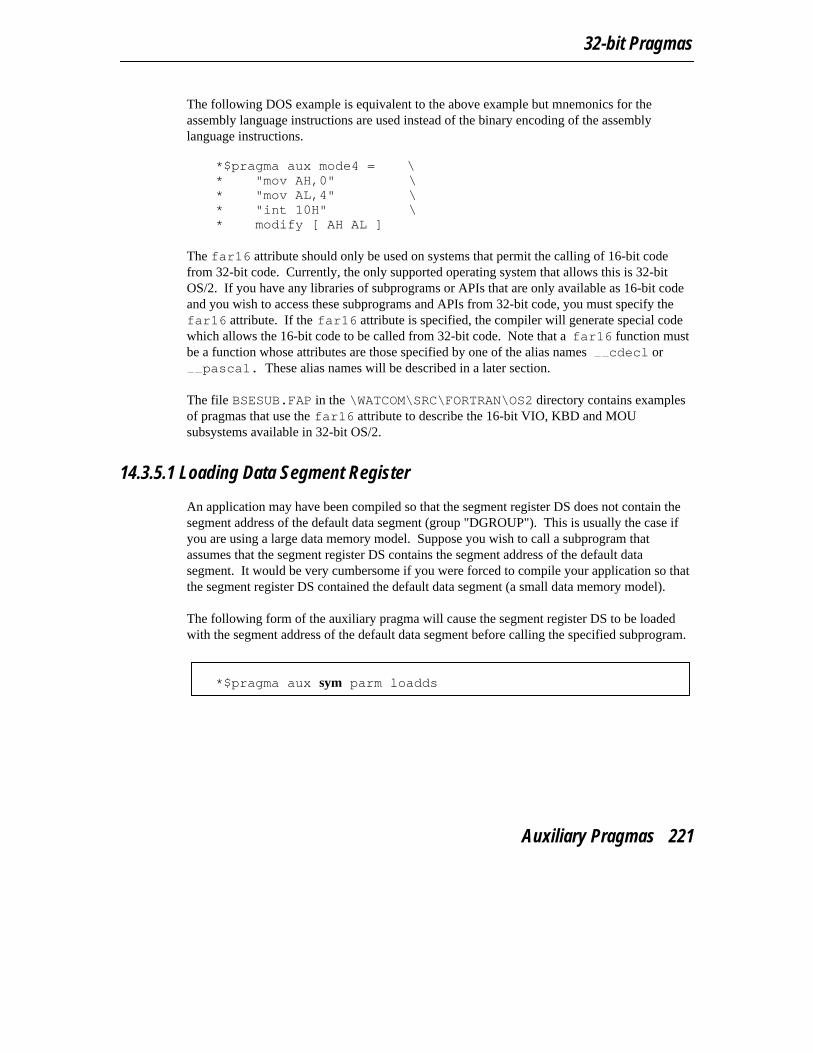
32-bit Pragmas
The following DOS example is equivalent to the above example but mnemonics for theassembly language instructions are used instead of the binary encoding of the assemblylanguage instructions.
*$pragma aux mode4 = \* "mov AH,0" \* "mov AL,4" \* "int 10H" \* modify [ AH AL ]
The far16 attribute should only be used on systems that permit the calling of 16-bit codefrom 32-bit code. Currently, the only supported operating system that allows this is 32-bitOS/2. If you have any libraries of subprograms or APIs that are only available as 16-bit codeand you wish to access these subprograms and APIs from 32-bit code, you must specify thefar16 attribute. If the far16 attribute is specified, the compiler will generate special codewhich allows the 16-bit code to be called from 32-bit code. Note that a far16 function mustbe a function whose attributes are those specified by one of the alias names cdecl orpascal. These alias names will be described in a later section.
The file BSESUB.FAP in the \WATCOM\SRC\FORTRAN\OS2 directory contains examplesof pragmas that use the far16 attribute to describe the 16-bit VIO, KBD and MOUsubsystems available in 32-bit OS/2.
14.3.5.1 Loading Data Segment Register
An application may have been compiled so that the segment register DS does not contain thesegment address of the default data segment (group "DGROUP"). This is usually the case ifyou are using a large data memory model. Suppose you wish to call a subprogram thatassumes that the segment register DS contains the segment address of the default datasegment. It would be very cumbersome if you were forced to compile your application so thatthe segment register DS contained the default data segment (a small data memory model).
The following form of the auxiliary pragma will cause the segment register DS to be loadedwith the segment address of the default data segment before calling the specified subprogram.
*$pragma aux sym parm loadds
Auxiliary Pragmas 221

32-bit Topics
where description:
sym is a subprogram name.
Alternatively, the following form of the auxiliary pragma will cause the segment register DSto be loaded with the segment address of the default data segment as part of the prologuesequence for the specified subprogram.
*$pragma aux sym loadds
where description:
sym is a subprogram name.
14.3.5.2 Defining Exported Symbols in Dynamic Link Libraries
An exported symbol in a dynamic link library is a symbol that can be referenced by anapplication that is linked with that dynamic link library. Normally, symbols in dynamic linklibraries are exported using the Watcom Linker "EXPORT" directive. An alternative methodis to use the following form of the auxiliary pragma.
*$pragma aux sym export
where description:
sym is a subprogram name.
14.3.6 Describing Argument Information
Using auxiliary pragmas, you can describe the calling convention that Watcom F77 is to usefor calling subprograms. This is particularly useful when interfacing to subprograms thathave been compiled by other compilers or subprograms written in other programminglanguages.
The general form of an auxiliary pragma that describes argument passing is the following.
222 Auxiliary Pragmas

32-bit Pragmas
*$pragma aux sym parm { arg_info | pop_info | reverse {reg_set} }
arg_info ::= ( arg_attr {, arg_attr} )
arg_attr ::= value [v_attr]| reference [r_attr]| data reference [d_attr]
v_attr ::= far | near | *1 | *2 | *4 | *8
r_attr ::= [far | near] [descriptor | nodescriptor]
d_attr ::= [far | near]
pop_info ::= caller | routine
where description:
sym is a subprogram name.
reg_set is called a register set. The register sets specify the registers that are to be usedfor argument passing. A register set is a list of registers separated by spaces andenclosed in square brackets.
14.3.6.1 Passing Arguments to non-FORTRAN Subprograms
When calling a subprogram written in a different language, it may be necessary to provide thearguments in a form different than the default methods used by Watcom F77. For example, Cfunctions require scalar arguments to be passed by value instead of by reference. Forinformation on the methods Watcom F77 uses to pass arguments, see the chapter entitled"Assembly Language Considerations".
The following form of the auxiliary pragma can be used to alter the default calling mechanismused for passing arguments.
Auxiliary Pragmas 223
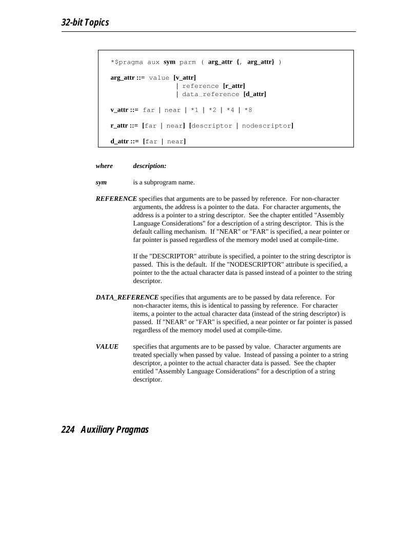
32-bit Topics
*$pragma aux sym parm ( arg_attr {, arg_attr} )
arg_attr ::= value [v_attr]| reference [r_attr]| data reference [d_attr]
v_attr ::= far | near | *1 | *2 | *4 | *8
r_attr ::= [far | near] [descriptor | nodescriptor]
d_attr ::= [far | near]
where description:
sym is a subprogram name.
REFERENCE specifies that arguments are to be passed by reference. For non-characterarguments, the address is a pointer to the data. For character arguments, theaddress is a pointer to a string descriptor. See the chapter entitled "AssemblyLanguage Considerations" for a description of a string descriptor. This is thedefault calling mechanism. If "NEAR" or "FAR" is specified, a near pointer orfar pointer is passed regardless of the memory model used at compile-time.
If the "DESCRIPTOR" attribute is specified, a pointer to the string descriptor ispassed. This is the default. If the "NODESCRIPTOR" attribute is specified, apointer to the the actual character data is passed instead of a pointer to the stringdescriptor.
DATA_REFERENCE specifies that arguments are to be passed by data reference. Fornon-character items, this is identical to passing by reference. For characteritems, a pointer to the actual character data (instead of the string descriptor) ispassed. If "NEAR" or "FAR" is specified, a near pointer or far pointer is passedregardless of the memory model used at compile-time.
VALUE specifies that arguments are to be passed by value. Character arguments aretreated specially when passed by value. Instead of passing a pointer to a stringdescriptor, a pointer to the actual character data is passed. See the chapterentitled "Assembly Language Considerations" for a description of a stringdescriptor.
224 Auxiliary Pragmas
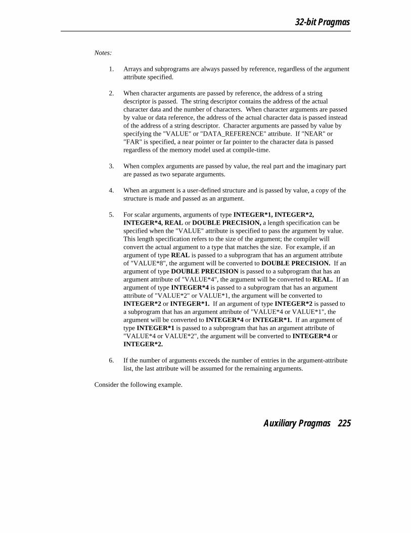
32-bit Pragmas
Notes:
1. Arrays and subprograms are always passed by reference, regardless of the argumentattribute specified.
2. When character arguments are passed by reference, the address of a stringdescriptor is passed. The string descriptor contains the address of the actualcharacter data and the number of characters. When character arguments are passedby value or data reference, the address of the actual character data is passed insteadof the address of a string descriptor. Character arguments are passed by value byspecifying the "VALUE" or "DATA_REFERENCE" attribute. If "NEAR" or"FAR" is specified, a near pointer or far pointer to the character data is passedregardless of the memory model used at compile-time.
3. When complex arguments are passed by value, the real part and the imaginary partare passed as two separate arguments.
4. When an argument is a user-defined structure and is passed by value, a copy of thestructure is made and passed as an argument.
5. For scalar arguments, arguments of type INTEGER*1, INTEGER*2,INTEGER*4, REAL or DOUBLE PRECISION, a length specification can bespecified when the "VALUE" attribute is specified to pass the argument by value.This length specification refers to the size of the argument; the compiler willconvert the actual argument to a type that matches the size. For example, if anargument of type REAL is passed to a subprogram that has an argument attributeof "VALUE*8", the argument will be converted to DOUBLE PRECISION. If anargument of type DOUBLE PRECISION is passed to a subprogram that has anargument attribute of "VALUE*4", the argument will be converted to REAL. If anargument of type INTEGER*4 is passed to a subprogram that has an argumentattribute of "VALUE*2" or VALUE*1, the argument will be converted toINTEGER*2 or INTEGER*1. If an argument of type INTEGER*2 is passed toa subprogram that has an argument attribute of "VALUE*4 or VALUE*1", theargument will be converted to INTEGER*4 or INTEGER*1. If an argument oftype INTEGER*1 is passed to a subprogram that has an argument attribute of"VALUE*4 or VALUE*2", the argument will be converted to INTEGER*4 orINTEGER*2.
6. If the number of arguments exceeds the number of entries in the argument-attributelist, the last attribute will be assumed for the remaining arguments.
Consider the following example.
Auxiliary Pragmas 225

32-bit Topics
*$pragma aux printf "* " parm (value) caller []
character cr/z0d/, nullchar/z00/call printf( ’values: %ld, %ld’//cr//nullchar,
1 77, 31410 )end
The C "printf" function is called with three arguments. The first argument is of typeCHARACTER and is passed as a C string (address of actual data terminated by a nullcharacter). The second and third arguments are passed by value. Also note that "printf" is afunction that takes a variable number of arguments, all passed on the stack (an empty registerset was specified), and that the caller must remove the arguments from the stack.
14.3.6.2 Passing Arguments in Registers
The following form of the auxiliary pragma can be used to specify the registers that are to beused to pass arguments to a particular subprogram.
*$pragma aux sym parm {reg_set}
where description:
sym is a subprogram name.
reg_set is called a register set. The register sets specify the registers that are to be usedfor argument passing. A register set is a list of registers separated by spaces andenclosed in square brackets.
Register sets establish a priority for register allocation during argument list processing.Register sets are processed from left to right. However, within a register set, registers arechosen in any order. Once all register sets have been processed, any remaining arguments arepushed on the stack.
Note that regardless of the register sets specified, only certain combinations of registers willbe selected for arguments of a particular type.
Note that arguments of type REAL and DOUBLE PRECISION are always pushed on thestack when the "fpi" or "fpi87" option is used.
226 Auxiliary Pragmas

32-bit Pragmas
DOUBLE PRECISIONArguments of type DOUBLE PRECISION, when passed by value, can only bepassed in one of the following register pairs: EDX:EAX, ECX:EBX,ECX:EAX, ECX:ESI, EDX:EBX, EDI:EAX, ECX:EDI, EDX:ESI, EDI:EBX,ESI:EAX, ECX:EDX, EDX:EDI, EDI:ESI, ESI:EBX or EBX:EAX. Forexample, if the following register set was specified for a routine having anargument of type DOUBLE PRECISION,
[EBP EBX]
the argument would be pushed on the stack since a valid register combinationfor 8-byte arguments is not contained in the register set. Note that this methodfor passing arguments of type DOUBLE PRECISION is supported only whenthe "fpc" option is used. Note that this argument passing method does notinclude arguments of type COMPLEX*8 or user-defined structures whose sizeis 8 bytes when these arguments are passed by value.
far pointer A far pointer can only be passed in one of the following register pairs:DX:EAX, CX:EBX, CX:EAX, CX:ESI, DX:EBX, DI:EAX, CX:EDI, DX:ESI,DI:EBX, SI:EAX, CX:EDX, DX:EDI, DI:ESI, SI:EBX, BX:EAX, FS:ECX,FS:EDX, FS:EDI, FS:ESI, FS:EBX, FS:EAX, GS:ECX, GS:EDX, GS:EDI,GS:ESI, GS:EBX, GS:EAX, DS:ECX, DS:EDX, DS:EDI, DS:ESI, DS:EBX,DS:EAX, ES:ECX, ES:EDX, ES:EDI, ES:ESI, ES:EBX or ES:EAX. Forexample, if a far pointer is passed to a function with the following register set,
[ES EBP]
the argument would be pushed on the stack since a valid register combinationfor a far pointer is not contained in the register set. Far pointers are used to passarguments by reference in a big data memory model.
INTEGER The only registers that will be assigned to 4-byte arguments (e.g., arguments oftype INTEGER when passed by value or arguments passed by reference in asmall data memory model) are: EAX, EBX, ECX, EDX, ESI and EDI. Forexample, if the following register set was specified for a routine with oneargument of type INTEGER,
[EBP]
the argument would be pushed on the stack since a valid register combinationfor 4-byte arguments is not contained in the register set. Note that this argumentpassing method also includes arguments of type REAL but only when the "fpc"option is used.
Auxiliary Pragmas 227
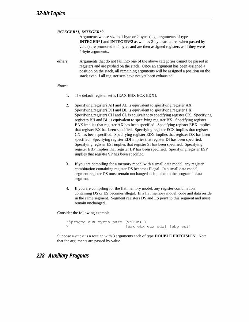
32-bit Topics
INTEGER*1, INTEGER*2Arguments whose size is 1 byte or 2 bytes (e.g., arguments of typeINTEGER*1 and INTEGER*2 as well as 2-byte structures when passed byvalue) are promoted to 4 bytes and are then assigned registers as if they were4-byte arguments.
others Arguments that do not fall into one of the above categories cannot be passed inregisters and are pushed on the stack. Once an argument has been assigned aposition on the stack, all remaining arguments will be assigned a position on thestack even if all register sets have not yet been exhausted.
Notes:
1. The default register set is [EAX EBX ECX EDX].
2. Specifying registers AH and AL is equivalent to specifying register AX.Specifying registers DH and DL is equivalent to specifying register DX.Specifying registers CH and CL is equivalent to specifying register CX. Specifyingregisters BH and BL is equivalent to specifying register BX. Specifying registerEAX implies that register AX has been specified. Specifying register EBX impliesthat register BX has been specified. Specifying register ECX implies that registerCX has been specified. Specifying register EDX implies that register DX has beenspecified. Specifying register EDI implies that register DI has been specified.Specifying register ESI implies that register SI has been specified. Specifyingregister EBP implies that register BP has been specified. Specifying register ESPimplies that register SP has been specified.
3. If you are compiling for a memory model with a small data model, any registercombination containing register DS becomes illegal. In a small data model,segment register DS must remain unchanged as it points to the program’s datasegment.
4. If you are compiling for the flat memory model, any register combinationcontaining DS or ES becomes illegal. In a flat memory model, code and data residein the same segment. Segment registers DS and ES point to this segment and mustremain unchanged.
Consider the following example. *$pragma aux myrtn parm (value) \* [eax ebx ecx edx] [ebp esi]
Suppose myrtn is a routine with 3 arguments each of type DOUBLE PRECISION. Notethat the arguments are passed by value.
228 Auxiliary Pragmas
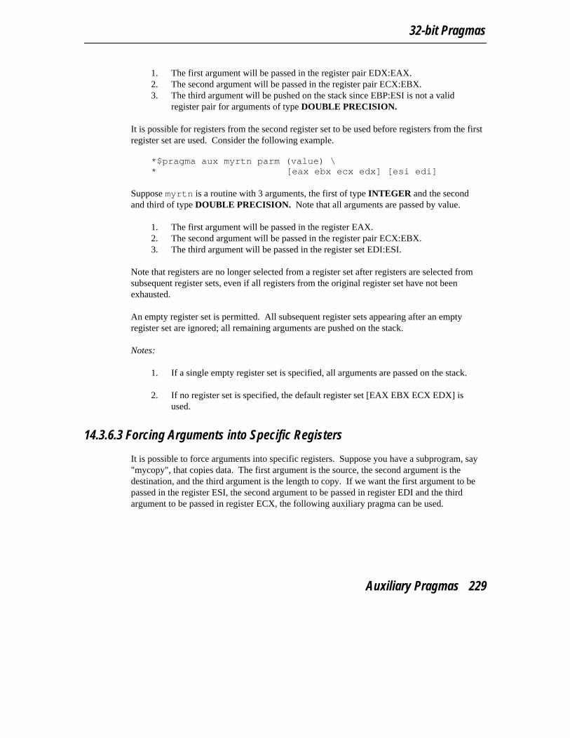
32-bit Pragmas
1. The first argument will be passed in the register pair EDX:EAX.2. The second argument will be passed in the register pair ECX:EBX.3. The third argument will be pushed on the stack since EBP:ESI is not a valid
register pair for arguments of type DOUBLE PRECISION.
It is possible for registers from the second register set to be used before registers from the firstregister set are used. Consider the following example.
*$pragma aux myrtn parm (value) \* [eax ebx ecx edx] [esi edi]
Suppose myrtn is a routine with 3 arguments, the first of type INTEGER and the secondand third of type DOUBLE PRECISION. Note that all arguments are passed by value.
1. The first argument will be passed in the register EAX.2. The second argument will be passed in the register pair ECX:EBX.3. The third argument will be passed in the register set EDI:ESI.
Note that registers are no longer selected from a register set after registers are selected fromsubsequent register sets, even if all registers from the original register set have not beenexhausted.
An empty register set is permitted. All subsequent register sets appearing after an emptyregister set are ignored; all remaining arguments are pushed on the stack.
Notes:
1. If a single empty register set is specified, all arguments are passed on the stack.
2. If no register set is specified, the default register set [EAX EBX ECX EDX] isused.
14.3.6.3 Forcing Arguments into Specific Registers
It is possible to force arguments into specific registers. Suppose you have a subprogram, say"mycopy", that copies data. The first argument is the source, the second argument is thedestination, and the third argument is the length to copy. If we want the first argument to bepassed in the register ESI, the second argument to be passed in register EDI and the thirdargument to be passed in register ECX, the following auxiliary pragma can be used.
Auxiliary Pragmas 229

32-bit Topics
*$pragma aux mycopy parm (value) \* [EDI] [ESI] [ECX]
character*10 dstcall mycopy( dst, ’0123456789’, 10 )...end
Note that you must be aware of the size of the arguments to ensure that the arguments getpassed in the appropriate registers.
14.3.6.4 Passing Arguments to In-Line Subprograms
For subprograms whose code is generated by Watcom F77 and whose argument list isdescribed by an auxiliary pragma, Watcom F77 has some freedom in choosing how argumentsare assigned to registers. Since the code for in-line subprograms is specified by theprogrammer, the description of the argument list must be very explicit. To achieve this,Watcom F77 assumes that each register set corresponds to an argument. Consider thefollowing DOS example of an in-line subprogram called scrollactivepgup.
*$pragma aux scrollactivepgup = \* "mov AH,6" \* "int 10h" \* parm (value) \* [ch] [cl] [dh] [dl] [al] [bh] \* modify [ah]
The BIOS video call to scroll the active page up requires the following arguments.
1. The row and column of the upper left corner of the scroll window is passed inregisters CH and CL respectively.
2. The row and column of the lower right corner of the scroll window is passed inregisters DH and DL respectively.
3. The number of lines blanked at the bottom of the window is passed in register AL.
4. The attribute to be used on the blank lines is passed in register BH.
When passing arguments, Watcom F77 will convert the argument so that it fits in theregister(s) specified in the register set for that argument. For example, in the above example,if the first argument to scrollactivepgup was called with an argument whose type wasINTEGER, it would first be converted to INTEGER*1 before assigning it to register CH.Similarly, if an in-line subprogram required its argument in register EAX and the argument
230 Auxiliary Pragmas
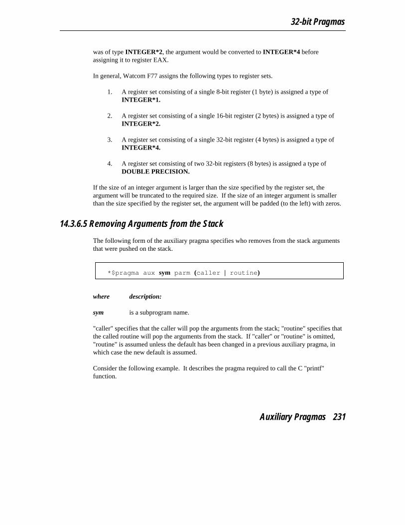
32-bit Pragmas
was of type INTEGER*2, the argument would be converted to INTEGER*4 beforeassigning it to register EAX.
In general, Watcom F77 assigns the following types to register sets.
1. A register set consisting of a single 8-bit register (1 byte) is assigned a type ofINTEGER*1.
2. A register set consisting of a single 16-bit register (2 bytes) is assigned a type ofINTEGER*2.
3. A register set consisting of a single 32-bit register (4 bytes) is assigned a type ofINTEGER*4.
4. A register set consisting of two 32-bit registers (8 bytes) is assigned a type ofDOUBLE PRECISION.
If the size of an integer argument is larger than the size specified by the register set, theargument will be truncated to the required size. If the size of an integer argument is smallerthan the size specified by the register set, the argument will be padded (to the left) with zeros.
14.3.6.5 Removing Arguments from the Stack
The following form of the auxiliary pragma specifies who removes from the stack argumentsthat were pushed on the stack.
*$pragma aux sym parm (caller | routine)
where description:
sym is a subprogram name.
"caller" specifies that the caller will pop the arguments from the stack; "routine" specifies thatthe called routine will pop the arguments from the stack. If "caller" or "routine" is omitted,"routine" is assumed unless the default has been changed in a previous auxiliary pragma, inwhich case the new default is assumed.
Consider the following example. It describes the pragma required to call the C "printf"function.
Auxiliary Pragmas 231

32-bit Topics
*$pragma aux printf "* " parm (value) caller []
character cr/z0d/, nullchar/z00/call printf( ’value is %ld’//cr//nullchar,
1 7143 )end
The first argument must be passed as a C string, a pointer to the actual character dataterminated by a null character. By default, the address of a string descriptor is passed forarguments of type CHARACTER. See the chapter entitled "Assembly LanguageConsiderations" for more information on string descriptors. The second argument is of typeINTEGER and is passed by value. Also note that "printf" is a function that takes a variablenumber of arguments, all pushed on the stack (an empty register set was specified).
14.3.6.6 Passing Arguments in Reverse Order
The following form of the auxiliary pragma specifies that arguments are passed in the reverseorder.
*$pragma aux sym parm reverse
where description:
sym is a subprogram name.
Normally, arguments are processed from left to right. The leftmost arguments are passed inregisters and the rightmost arguments are passed on the stack (if the registers used forargument passing have been exhausted). Arguments that are passed on the stack are pushedfrom right to left.
When arguments are reversed, the rightmost arguments are passed in registers and the leftmostarguments are passed on the stack (if the registers used for argument passing have beenexhausted). Arguments that are passed on the stack are pushed from left to right.
Reversing arguments is most useful for subprograms that require arguments to be passed onthe stack in an order opposite from the default. The following auxiliary pragma demonstratessuch a subprogram.
*$pragma aux rtn parm reverse []
232 Auxiliary Pragmas
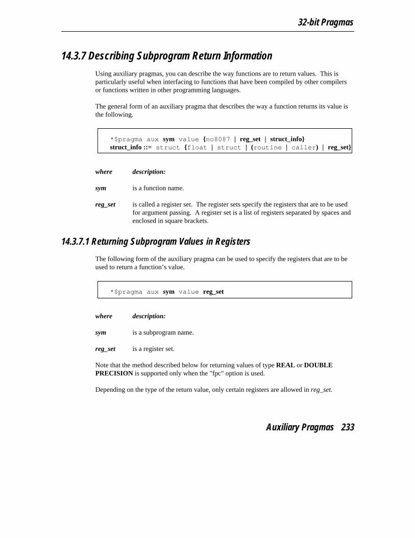
32-bit Pragmas
14.3.7 Describing Subprogram Return Information
Using auxiliary pragmas, you can describe the way functions are to return values. This isparticularly useful when interfacing to functions that have been compiled by other compilersor functions written in other programming languages.
The general form of an auxiliary pragma that describes the way a function returns its value isthe following.
*$pragma aux sym value {no8087 | reg_set | struct_info} struct_info ::= struct {float | struct | (routine | caller) | reg_set}
where description:
sym is a function name.
reg_set is called a register set. The register sets specify the registers that are to be usedfor argument passing. A register set is a list of registers separated by spaces andenclosed in square brackets.
14.3.7.1 Returning Subprogram Values in Registers
The following form of the auxiliary pragma can be used to specify the registers that are to beused to return a function’s value.
*$pragma aux sym value reg_set
where description:
sym is a subprogram name.
reg_set is a register set.
Note that the method described below for returning values of type REAL or DOUBLEPRECISION is supported only when the "fpc" option is used.
Depending on the type of the return value, only certain registers are allowed in reg_set.
Auxiliary Pragmas 233
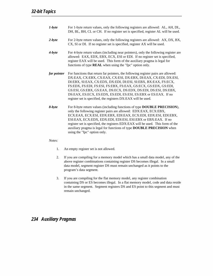
32-bit Topics
1-byte For 1-byte return values, only the following registers are allowed: AL, AH, DL,DH, BL, BH, CL or CH. If no register set is specified, register AL will be used.
2-byte For 2-byte return values, only the following registers are allowed: AX, DX, BX,CX, SI or DI. If no register set is specified, register AX will be used.
4-byte For 4-byte return values (including near pointers), only the following register areallowed: EAX, EDX, EBX, ECX, ESI or EDI. If no register set is specified,register EAX will be used. This form of the auxiliary pragma is legal forfunctions of type REAL when using the "fpc" option only.
far pointer For functions that return far pointers, the following register pairs are allowed:DX:EAX, CX:EBX, CX:EAX, CX:ESI, DX:EBX, DI:EAX, CX:EDI, DX:ESI,DI:EBX, SI:EAX, CX:EDX, DX:EDI, DI:ESI, SI:EBX, BX:EAX, FS:ECX,FS:EDX, FS:EDI, FS:ESI, FS:EBX, FS:EAX, GS:ECX, GS:EDX, GS:EDI,GS:ESI, GS:EBX, GS:EAX, DS:ECX, DS:EDX, DS:EDI, DS:ESI, DS:EBX,DS:EAX, ES:ECX, ES:EDX, ES:EDI, ES:ESI, ES:EBX or ES:EAX. If noregister set is specified, the registers DX:EAX will be used.
8-byte For 8-byte return values (including functions of type DOUBLE PRECISION),only the following register pairs are allowed: EDX:EAX, ECX:EBX,ECX:EAX, ECX:ESI, EDX:EBX, EDI:EAX, ECX:EDI, EDX:ESI, EDI:EBX,ESI:EAX, ECX:EDX, EDX:EDI, EDI:ESI, ESI:EBX or EBX:EAX. If noregister set is specified, the registers EDX:EAX will be used. This form of theauxiliary pragma is legal for functions of type DOUBLE PRECISION whenusing the "fpc" option only.
Notes:
1. An empty register set is not allowed.
2. If you are compiling for a memory model which has a small data model, any of theabove register combinations containing register DS becomes illegal. In a smalldata model, segment register DS must remain unchanged as it points to theprogram’s data segment.
3. If you are compiling for the flat memory model, any register combinationcontaining DS or ES becomes illegal. In a flat memory model, code and data residein the same segment. Segment registers DS and ES point to this segment and mustremain unchanged.
234 Auxiliary Pragmas
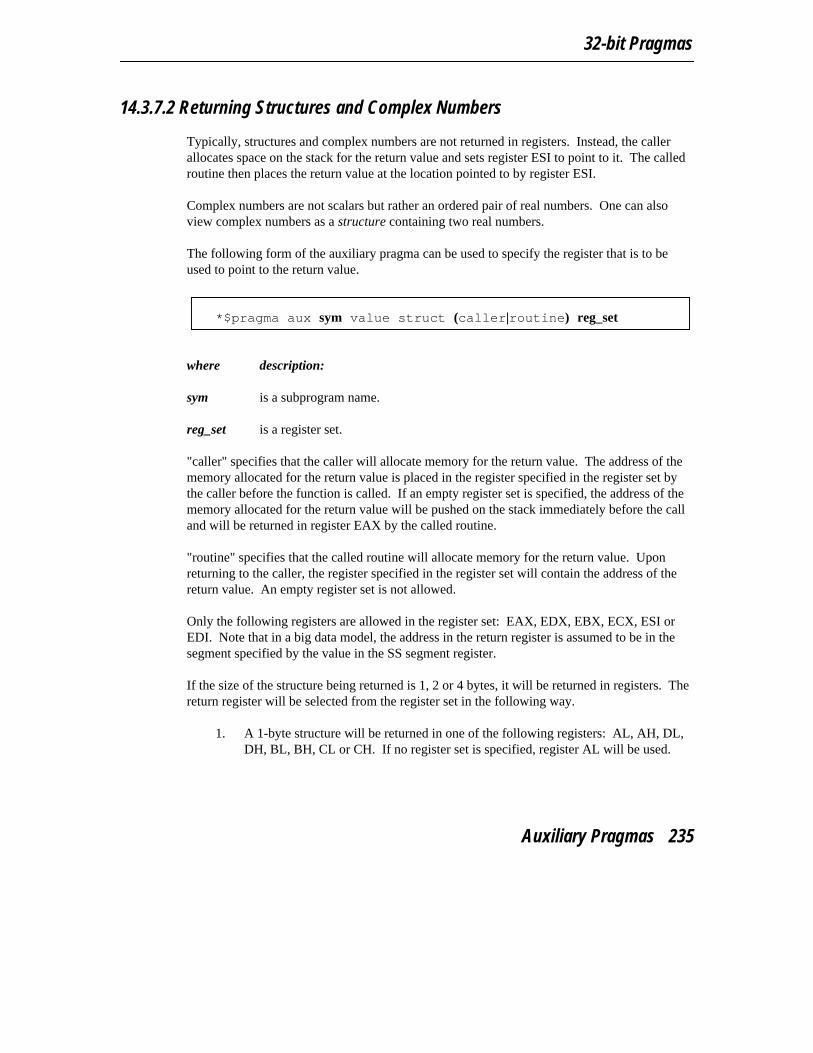
32-bit Pragmas
14.3.7.2 Returning Structures and Complex Numbers
Typically, structures and complex numbers are not returned in registers. Instead, the callerallocates space on the stack for the return value and sets register ESI to point to it. The calledroutine then places the return value at the location pointed to by register ESI.
Complex numbers are not scalars but rather an ordered pair of real numbers. One can alsoview complex numbers as a structure containing two real numbers.
The following form of the auxiliary pragma can be used to specify the register that is to beused to point to the return value.
*$pragma aux sym value struct (caller|routine) reg_set
where description:
sym is a subprogram name.
reg_set is a register set.
"caller" specifies that the caller will allocate memory for the return value. The address of thememory allocated for the return value is placed in the register specified in the register set bythe caller before the function is called. If an empty register set is specified, the address of thememory allocated for the return value will be pushed on the stack immediately before the calland will be returned in register EAX by the called routine.
"routine" specifies that the called routine will allocate memory for the return value. Uponreturning to the caller, the register specified in the register set will contain the address of thereturn value. An empty register set is not allowed.
Only the following registers are allowed in the register set: EAX, EDX, EBX, ECX, ESI orEDI. Note that in a big data model, the address in the return register is assumed to be in thesegment specified by the value in the SS segment register.
If the size of the structure being returned is 1, 2 or 4 bytes, it will be returned in registers. Thereturn register will be selected from the register set in the following way.
1. A 1-byte structure will be returned in one of the following registers: AL, AH, DL,DH, BL, BH, CL or CH. If no register set is specified, register AL will be used.
Auxiliary Pragmas 235

32-bit Topics
2. A 2-byte structure will be returned in one of the following registers: AX, DX, BX,CX, SI or DI. If no register set is specified, register AX will be used.
3. A 4-byte structure will be returned in one of the following registers: EAX, EDX,EBX, ECX, ESI or EDI. If no register set is specified, register EAX will be used.
The following form of the auxiliary pragma can be used to specify that structures whose sizeis 1, 2 or 4 bytes are not to be returned in registers. Instead, the caller will allocate space onthe stack for the structure return value and point register ESI to it.
*$pragma aux sym value struct struct
where description:
sym is a subprogram name.
14.3.7.3 Returning Floating-Point Data
There are a few ways available for specifying how the value for a function whose type isREAL or DOUBLE PRECISION is to be returned.
The following form of the auxiliary pragma can be used to specify that function return valueswhose type is REAL or DOUBLE PRECISION are not to be returned in registers. Instead,the caller will allocate space on the stack for the return value and point register ESI to it.
*$pragma aux sym value struct float
where description:
sym is a function name.
In other words, floating-point values are to be returned in the same way complex numbers arereturned.
The following form of the auxiliary pragma can be used to specify that function return valueswhose type is REAL or DOUBLE PRECISION are not to be returned in 80x87 registerswhen compiling with the "fpi" or "fpi87" option. Instead, the value will be returned in 80x86registers. This is the default behaviour for the "fpc" option. Function return values whosetype is REAL will be returned in register EAX. Function return values whose type is
236 Auxiliary Pragmas
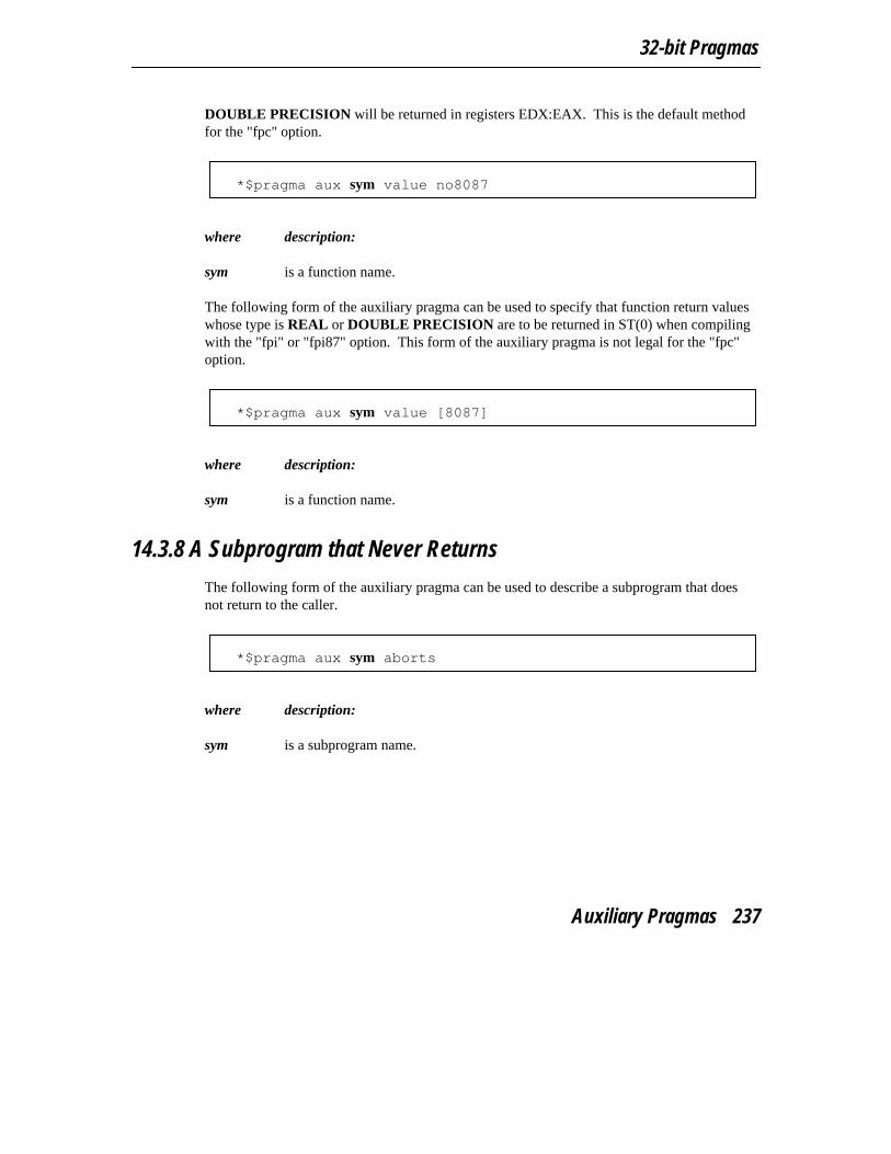
32-bit Pragmas
DOUBLE PRECISION will be returned in registers EDX:EAX. This is the default methodfor the "fpc" option.
*$pragma aux sym value no8087
where description:
sym is a function name.
The following form of the auxiliary pragma can be used to specify that function return valueswhose type is REAL or DOUBLE PRECISION are to be returned in ST(0) when compilingwith the "fpi" or "fpi87" option. This form of the auxiliary pragma is not legal for the "fpc"option.
*$pragma aux sym value [8087]
where description:
sym is a function name.
14.3.8 A Subprogram that Never Returns
The following form of the auxiliary pragma can be used to describe a subprogram that doesnot return to the caller.
*$pragma aux sym aborts
where description:
sym is a subprogram name.
Auxiliary Pragmas 237

32-bit Topics
Consider the following example. *$pragma aux exitrtn aborts
...call exitrtn()end
exitrtn is defined to be a function that does not return. For example, it may call exit toreturn to the system. In this case, Watcom F77 generates a "jmp" instruction instead of a"call" instruction to invoke exitrtn.
14.3.9 Describing How Subprograms Use Variables in Common
The following form of the auxiliary pragma can be used to describe a subprogram that doesnot modify any variable that appears in a common block defined by the caller.
*$pragma aux sym modify nomemory
where description:
sym is a subprogram name.
Consider the following example.
integer icommon /blk/ iwhile( i .lt. 1000 )do
i = i + 383endwhilecall myrtn()i = i + 13143end
block datacommon /blk/ iinteger i/1033/end
To compile the above program, "rtn.for", we issue the following command. C>wfc rtn /mm /d1C>wfc386 rtn /d1
238 Auxiliary Pragmas

32-bit Pragmas
The "d1" compiler option is specified so that the object file produced by Watcom F77contains source line information.
We can generate a file containing a disassembly of RTN.OBJ by issuing the followingcommand.
C>wdis rtn /l /s /r
The "s" option is specified so that the listing file produced by the Watcom Disassemblercontains source lines taken from RTN.FOR. The listing file RTN.LST appears as follows.
Module: rtn.forGroup: ’DGROUP’ DATA,LDATA,CDATA,BLK
Segment: ’FMAIN TEXT’ BYTE USE32 00000036 bytes
integer icommon /blk/ i
0000 52 FMAIN push edx0001 8b 15 00 00 00 00 mov edx,L3
while( i .lt. 1000 )do0007 81 fa e8 03 00 00 L1 cmp edx,000003e8H000d 7d 08 jge L2
i = i + 383endwhile
000f 81 c2 7f 01 00 00 add edx,0000017fH0015 eb f0 jmp L1
call myrtn()0017 89 15 00 00 00 00 L2 mov L3,edx001d e8 00 00 00 00 call MYRTN0022 8b 15 00 00 00 00 mov edx,L3
i = i + 131430028 81 c2 57 33 00 00 add edx,00003357H002e 89 15 00 00 00 00 mov L3,edx
end
block datacommon /blk/ iinteger i/1033/end
0034 5a pop edx0035 c3 ret
No disassembly errors
Auxiliary Pragmas 239
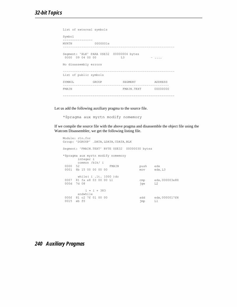
32-bit Topics
List of external symbols
Symbol----------------MYRTN 0000001e------------------------------------------------------------
Segment: ’BLK’ PARA USE32 00000004 bytes0000 09 04 00 00 L3 - ....
No disassembly errors
------------------------------------------------------------List of public symbols
SYMBOL GROUP SEGMENT ADDRESS---------------------------------------------------------FMAIN FMAIN TEXT 00000000
------------------------------------------------------------
Let us add the following auxiliary pragma to the source file. *$pragma aux myrtn modify nomemory
If we compile the source file with the above pragma and disassemble the object file using theWatcom Disassembler, we get the following listing file.
Module: rtn.forGroup: ’DGROUP’ DATA,LDATA,CDATA,BLK
Segment: ’FMAIN TEXT’ BYTE USE32 00000030 bytes
*$pragma aux myrtn modify nomemoryinteger icommon /blk/ i
0000 52 FMAIN push edx0001 8b 15 00 00 00 00 mov edx,L3
while( i .lt. 1000 )do0007 81 fa e8 03 00 00 L1 cmp edx,000003e8H000d 7d 08 jge L2
i = i + 383endwhile
000f 81 c2 7f 01 00 00 add edx,0000017fH0015 eb f0 jmp L1
240 Auxiliary Pragmas

32-bit Pragmas
call myrtn()0017 89 15 00 00 00 00 L2 mov L3,edx001d e8 00 00 00 00 call MYRTN
i = i + 131430022 81 c2 57 33 00 00 add edx,00003357H0028 89 15 00 00 00 00 mov L3,edx
end
block datacommon /blk/ iinteger i/1033/end
002e 5a pop edx002f c3 ret
No disassembly errors
List of external symbols
Symbol----------------MYRTN 0000001e------------------------------------------------------------
Segment: ’BLK’ PARA USE32 00000004 bytes0000 09 04 00 00 L3 - ....
No disassembly errors
------------------------------------------------------------List of public symbols
SYMBOL GROUP SEGMENT ADDRESS---------------------------------------------------------FMAIN FMAIN TEXT 00000000
------------------------------------------------------------
Notice that the value of i is in register EDX after completion of the "while" loop. After thecall to myrtn, the value of i is not loaded from memory into a register to perform the finaladdition. The auxiliary pragma informs the compiler that myrtn does not modify anyvariable that appears in a common block defined by Rtn and hence register EDX contains thecorrect value of i.
The preceding auxiliary pragma deals with routines that modify variables in common. Let usconsider the case where routines reference variables in common. The following form of theauxiliary pragma can be used to describe a subprogram that does not reference any variablethat appears in a common block defined by the caller.
Auxiliary Pragmas 241
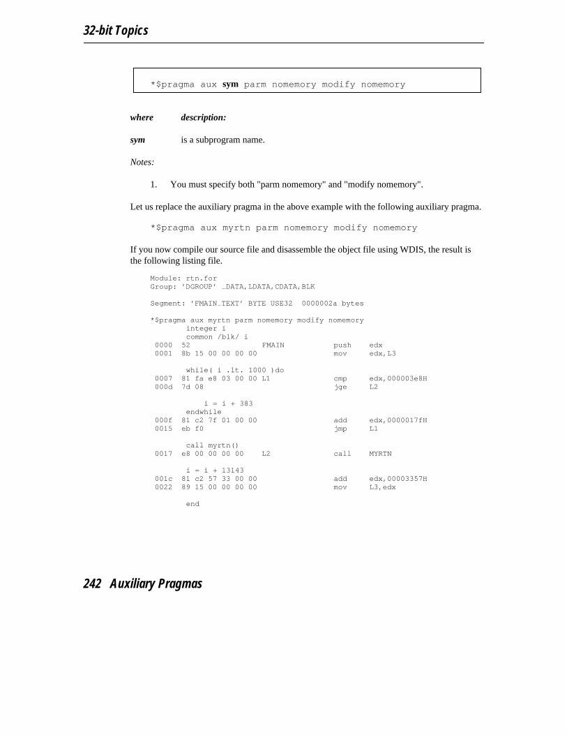
32-bit Topics
*$pragma aux sym parm nomemory modify nomemory
where description:
sym is a subprogram name.
Notes:
1. You must specify both "parm nomemory" and "modify nomemory".
Let us replace the auxiliary pragma in the above example with the following auxiliary pragma. *$pragma aux myrtn parm nomemory modify nomemory
If you now compile our source file and disassemble the object file using WDIS, the result isthe following listing file.
Module: rtn.forGroup: ’DGROUP’ DATA,LDATA,CDATA,BLK
Segment: ’FMAIN TEXT’ BYTE USE32 0000002a bytes
*$pragma aux myrtn parm nomemory modify nomemoryinteger icommon /blk/ i
0000 52 FMAIN push edx0001 8b 15 00 00 00 00 mov edx,L3
while( i .lt. 1000 )do0007 81 fa e8 03 00 00 L1 cmp edx,000003e8H000d 7d 08 jge L2
i = i + 383endwhile
000f 81 c2 7f 01 00 00 add edx,0000017fH0015 eb f0 jmp L1
call myrtn()0017 e8 00 00 00 00 L2 call MYRTN
i = i + 13143001c 81 c2 57 33 00 00 add edx,00003357H0022 89 15 00 00 00 00 mov L3,edx
end
242 Auxiliary Pragmas

32-bit Pragmas
block datacommon /blk/ iinteger i/1033/end
0028 5a pop edx0029 c3 ret
No disassembly errors
List of external symbols
Symbol----------------MYRTN 00000018------------------------------------------------------------
Segment: ’BLK’ PARA USE32 00000004 bytes0000 09 04 00 00 L3 - ....
No disassembly errors
------------------------------------------------------------List of public symbols
SYMBOL GROUP SEGMENT ADDRESS---------------------------------------------------------FMAIN FMAIN TEXT 00000000
------------------------------------------------------------
Notice that after completion of the "while" loop we did not have to update i with the value inregister EDX before calling myrtn. The auxiliary pragma informs the compiler that myrtndoes not reference any variable that appears in a common block defined by myrtn soupdating i was not necessary before calling myrtn.
14.3.10 Describing the Registers Modified by a Subprogram
The following form of the auxiliary pragma can be used to describe the registers that asubprogram will use without saving.
*$pragma aux sym modify [exact] reg_set
Auxiliary Pragmas 243
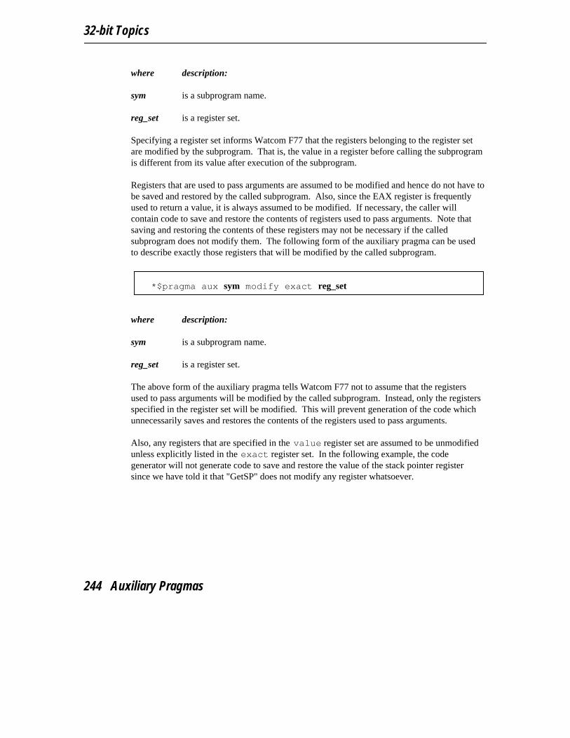
32-bit Topics
where description:
sym is a subprogram name.
reg_set is a register set.
Specifying a register set informs Watcom F77 that the registers belonging to the register setare modified by the subprogram. That is, the value in a register before calling the subprogramis different from its value after execution of the subprogram.
Registers that are used to pass arguments are assumed to be modified and hence do not have tobe saved and restored by the called subprogram. Also, since the EAX register is frequentlyused to return a value, it is always assumed to be modified. If necessary, the caller willcontain code to save and restore the contents of registers used to pass arguments. Note thatsaving and restoring the contents of these registers may not be necessary if the calledsubprogram does not modify them. The following form of the auxiliary pragma can be usedto describe exactly those registers that will be modified by the called subprogram.
*$pragma aux sym modify exact reg_set
where description:
sym is a subprogram name.
reg_set is a register set.
The above form of the auxiliary pragma tells Watcom F77 not to assume that the registersused to pass arguments will be modified by the called subprogram. Instead, only the registersspecified in the register set will be modified. This will prevent generation of the code whichunnecessarily saves and restores the contents of the registers used to pass arguments.
Also, any registers that are specified in the value register set are assumed to be unmodifiedunless explicitly listed in the exact register set. In the following example, the codegenerator will not generate code to save and restore the value of the stack pointer registersince we have told it that "GetSP" does not modify any register whatsoever.
244 Auxiliary Pragmas
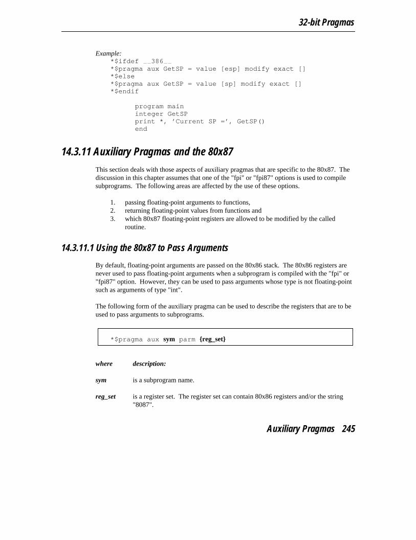
32-bit Pragmas
Example:*$ifdef 386*$pragma aux GetSP = value [esp] modify exact []*$else*$pragma aux GetSP = value [sp] modify exact []*$endif
program maininteger GetSPprint *, ’Current SP =’, GetSP()end
14.3.11 Auxiliary Pragmas and the 80x87
This section deals with those aspects of auxiliary pragmas that are specific to the 80x87. Thediscussion in this chapter assumes that one of the "fpi" or "fpi87" options is used to compilesubprograms. The following areas are affected by the use of these options.
1. passing floating-point arguments to functions,2. returning floating-point values from functions and3. which 80x87 floating-point registers are allowed to be modified by the called
routine.
14.3.11.1 Using the 80x87 to Pass Arguments
By default, floating-point arguments are passed on the 80x86 stack. The 80x86 registers arenever used to pass floating-point arguments when a subprogram is compiled with the "fpi" or"fpi87" option. However, they can be used to pass arguments whose type is not floating-pointsuch as arguments of type "int".
The following form of the auxiliary pragma can be used to describe the registers that are to beused to pass arguments to subprograms.
*$pragma aux sym parm {reg_set}
where description:
sym is a subprogram name.
reg_set is a register set. The register set can contain 80x86 registers and/or the string"8087".
Auxiliary Pragmas 245
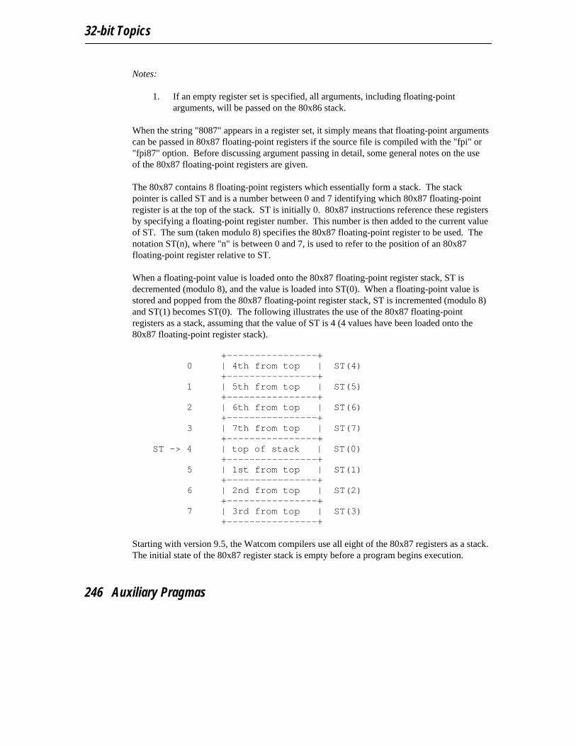
32-bit Topics
Notes:
1. If an empty register set is specified, all arguments, including floating-pointarguments, will be passed on the 80x86 stack.
When the string "8087" appears in a register set, it simply means that floating-point argumentscan be passed in 80x87 floating-point registers if the source file is compiled with the "fpi" or"fpi87" option. Before discussing argument passing in detail, some general notes on the useof the 80x87 floating-point registers are given.
The 80x87 contains 8 floating-point registers which essentially form a stack. The stackpointer is called ST and is a number between 0 and 7 identifying which 80x87 floating-pointregister is at the top of the stack. ST is initially 0. 80x87 instructions reference these registersby specifying a floating-point register number. This number is then added to the current valueof ST. The sum (taken modulo 8) specifies the 80x87 floating-point register to be used. Thenotation ST(n), where "n" is between 0 and 7, is used to refer to the position of an 80x87floating-point register relative to ST.
When a floating-point value is loaded onto the 80x87 floating-point register stack, ST isdecremented (modulo 8), and the value is loaded into ST(0). When a floating-point value isstored and popped from the 80x87 floating-point register stack, ST is incremented (modulo 8)and ST(1) becomes ST(0). The following illustrates the use of the 80x87 floating-pointregisters as a stack, assuming that the value of ST is 4 (4 values have been loaded onto the80x87 floating-point register stack).
+----------------+
0 | 4th from top | ST(4)+----------------+
1 | 5th from top | ST(5)+----------------+
2 | 6th from top | ST(6)+----------------+
3 | 7th from top | ST(7)+----------------+
ST -> 4 | top of stack | ST(0)+----------------+
5 | 1st from top | ST(1)+----------------+
6 | 2nd from top | ST(2)+----------------+
7 | 3rd from top | ST(3)+----------------+
Starting with version 9.5, the Watcom compilers use all eight of the 80x87 registers as a stack.The initial state of the 80x87 register stack is empty before a program begins execution.
246 Auxiliary Pragmas
32-bit Pragmas
Note: For compatibility with code compiled with version 9.0 and earlier, you cancompile with the "fpr" option. In this case only four of the eight 80x87 registersare used as a stack. These four registers were used to pass arguments. The otherfour registers form what was called the 80x87 cache. The cache was used forlocal floating-point variables. The state of the 80x87 registers before a programbegan execution was as follows.
1. The four 80x87 floating-point registers that form the stack areuninitialized.
2. The four 80x87 floating-point registers that form the 80x87 cache areinitialized with zero.
Hence, initially the 80x87 cache was comprised of ST(0), ST(1), ST(2) andST(3). ST had the value 4 as in the above diagram. When a floating-point valuewas pushed on the stack (as is the case when passing floating-point arguments),it became ST(0) and the 80x87 cache was comprised of ST(1), ST(2), ST(3) andST(4). When the 80x87 stack was full, ST(0), ST(1), ST(2) and ST(3) formedthe stack and ST(4), ST(5), ST(6) and ST(7) formed the 80x87 cache. Version9.5 and later no longer use this strategy.
The rules for passing arguments are as follows.
1. If the argument is not floating-point, use the procedure described earlier in thischapter.
2. If the argument is floating-point, and a previous argument has been assigned aposition on the 80x86 stack (instead of the 80x87 stack), the floating-pointargument is also assigned a position on the 80x86 stack. Otherwise proceed to thenext step.
3. If the string "8087" appears in a register set in the pragma, and if the 80x87 stack isnot full, the floating-point argument is assigned floating-point register ST(0) (thetop element of the 80x87 stack). The previous top element (if there was one) isnow in ST(1). Since arguments are pushed on the stack from right to left, theleftmost floating-point argument will be in ST(0). Otherwise the floating-pointargument is assigned a position on the 80x86 stack.
Consider the following example.
Auxiliary Pragmas 247

32-bit Topics
*$pragma aux myrtn parm (value) [8087];
real xdouble precision yinteger iinteger jx = 7.7i = 7y = 77.77j = 77call myrtn( x, i, y, j )end
myrtn is an assembly language subprogram that requires four arguments. The first argumentof type REAL (4 bytes), the second argument is of type INTEGER (4 bytes), the thirdargument is of type DOUBLE PRECISION (8 bytes) and the fourth argument is of typeINTEGER*4 (4 bytes). These arguments will be passed to myrtn in the following way.
1. Since "8087" was specified in the register set, the first argument, being of typeREAL, will be passed in an 80x87 floating-point register.
2. The second argument will be passed on the stack since no 80x86 registers werespecified in the register set.
3. The third argument will also be passed on the stack. Remember the following rule:once an argument is assigned a position on the stack, all remaining arguments willbe assigned a position on the stack. Note that the above rule holds even thoughthere are some 80x87 floating-point registers available for passing floating-pointarguments.
4. The fourth argument will also be passed on the stack.
Let us change the auxiliary pragma in the above example as follows. *$pragma aux myrtn parm [eax 8087]
The arguments will now be passed to myrtn in the following way.
1. Since "8087" was specified in the register set, the first argument, being of typeREAL will be passed in an 80x87 floating-point register.
2. The second argument will be passed in register EAX, exhausting the set ofavailable 80x86 registers for argument passing.
248 Auxiliary Pragmas

32-bit Pragmas
3. The third argument, being of type DOUBLE PRECISION, will also be passed inan 80x87 floating-point register.
4. The fourth argument will be passed on the stack since no 80x86 registers remain inthe register set.
14.3.11.2 Using the 80x87 to Return Subprogram Values
The following form of the auxiliary pragma can be used to describe a subprogram that returnsa floating-point value in ST(0).
*$pragma aux sym value reg_set
where description:
sym is a subprogram name.
reg_set is a register set containing the string "8087", i.e. [8087].
14.3.11.3 Preserving 80x87 Floating-Point Registers Across Calls
The code generator assumes that all eight 80x87 floating-point registers are available for usewithin a subprogram unless the "fpr" option is used to generate backward compatible code(older Watcom compilers used four registers as a cache). The following form of the auxiliarypragma specifies that the floating-point registers in the 80x87 cache may be modified by thespecified subprogram.
*$pragma aux sym modify reg_set
where description:
sym is a subprogram name.
reg_set is a register set containing the string "8087", i.e. [8087].
This instructs Watcom F77 to save any local variables that are located in the 80x87 cachebefore calling the specified routine.
Auxiliary Pragmas 249

32-bit Topics
250 Auxiliary Pragmas

Appendices

Appendices
252

Use of Environment Variables
A. Use of Environment Variables
In the Watcom FORTRAN 77 software development package, a number of environmentvariables are used. This appendix summarizes their use with a particular component of thepackage.
A.1 FINCLUDEThe FINCLUDE environment variable describes the location of the Watcom FORTRAN 77include files. This variable is used by Watcom FORTRAN 77.
SET FINCLUDE=[d:][path];[d:][path]...
The FINCLUDE environment string is like the PATH string in that you can specify one ormore directories separated by semicolons (";").
A.2 LIBThe use of the WATCOM environment variable and the Watcom Linker "SYSTEM"directive is recommended over the use of this environment variable.
The LIB environment variable is used to select the libraries that will be used when theapplication is linked. This variable is used by the Watcom Linker (WLINK.EXE). The LIBenvironment string is like the PATH string in that you can specify one or more directoriesseparated by semicolons (";").
If you have the 286 development system, 16-bit applications can be linked for DOS,Microsoft Windows, OS/2, and QNX depending on which libraries are selected. If you havethe 386 development system, 32-bit applications can be linked for DOS Extender systems,Microsoft Windows and QNX.
LIB 253
Appendices
A.3 LIBDOSThe use of the WATCOM environment variable and the Watcom Linker "SYSTEM"directive is recommended over the use of this environment variable.
If you are developing a DOS application, the LIBDOS environment variable must include thelocation of the 16-bit Watcom F77 DOS library files (files with the ".lib" filename extension).This variable is used by the Watcom Linker (WLINK.EXE). The default installation directoryfor the 16-bit Watcom F77 DOS libraries is \WATCOM\LIB286\DOS.
Example:C>set libdos=c:\watcom\lib286\dos
A.4 LIBWINThe use of the WATCOM environment variable and the Watcom Linker "SYSTEM"directive is recommended over the use of this environment variable.
If you are developing a 16-bit Microsoft Windows application, the LIBWIN environmentvariable must include the location of the 16-bit Watcom F77 Windows library files (files withthe ".lib" filename extension). This variable is used by the Watcom Linker (WLINK.EXE). Ifyou are developing a 32-bit Microsoft Windows application, see the description of theLIBPHAR environment variable. The default installation directory for the 16-bit WatcomF77 Windows libraries is \WATCOM\LIB286\WIN.
Example:C>set libwin=c:\watcom\lib286\win
A.5 LIBOS2The use of the WATCOM environment variable and the Watcom Linker "SYSTEM"directive is recommended over the use of this environment variable.
If you are developing an OS/2 application, the LIBOS2 environment variable must includethe location of the 16-bit Watcom F77 OS/2 library files (files with the ".lib" filenameextension). This variable is used by the Watcom Linker (WLINK.EXE). The defaultinstallation directory for the 16-bit Watcom F77 OS/2 libraries is \WATCOM\LIB286\OS2.The LIBOS2 environment variable must also include the directory of the OS/2DOSCALLS.LIB file which is usually \OS2.
254 LIBOS2

Use of Environment Variables
Example:C>set libos2=c:\watcom\lib286\os2;c:\os2
A.6 LIBPHARThe use of the WATCOM environment variable and the Watcom Linker "SYSTEM"directive is recommended over the use of this environment variable.
If you are developing a 32-bit Windows or DOS Extender application, the LIBPHARenvironment variable must include the location of the 32-bit Watcom F77 DOS Extenderlibrary files or the 32-bit Watcom F77 Windows library files (files with the ".lib" filenameextension). This variable is used by the Watcom Linker (WLINK.EXE). The defaultinstallation directory for the 32-bit Watcom F77 DOS Extender libraries is\WATCOM\LIB386\DOS. The default installation directory for the 32-bit Watcom F77Windows libraries is \WATCOM\LIB386\WIN.
Example:C>set libphar=c:\watcom\lib386\dos
orC>set libphar=c:\watcom\lib386\win
A.7 NO87The NO87 environment variable is checked by the Watcom FORTRAN 77 run-time librariesthat include floating-point emulation support. Normally, these libraries will detect thepresence of a numeric data processor (80x87) and use it. If you have a numeric data processorin your system but you wish to test a version of your application that will use floating-pointemulation, you can define the NO87 environment variable. Using the "SET" command,define the environment variable as follows:
SET NO87=1
Now, when you run your application, the 80x87 will be ignored. To undefine theenvironment variable, enter the command:
SET NO87=
NO87 255

Appendices
A.8 PATHThe PATH environment variable is used by DOS "COMMAND.COM" or OS/2 "CMD.EXE"to locate programs.
PATH [d:][path];[d:][path]...
The PATH environment variable should include the disk and directory of the WatcomFORTRAN 77 binary program files when using Watcom FORTRAN 77 and its related tools.
If your host system is DOS:
The default installation directory for 16-bit Watcom F77 and 32-bit Watcom F77 DOSbinaries is called \WATCOM\BINW.
Example:C>path c:\watcom\binw;c:\dos;c:\windows
If your host system is OS/2:
The default installation directories for 16-bit Watcom F77 and 32-bit Watcom F77 OS/2binaries are called \WATCOM\BINP and \WATCOM\BINW.
Example:[C:\]path c:\watcom\binp;c:\watcom\binw
If your host system is Windows NT:
The default installation directories for 16-bit Watcom F77 and 32-bit Watcom F77 WindowsNT binaries are called \WATCOM\BINNT and \WATCOM\BINW.
Example:C>path c:\watcom\binnt;c:\watcom\binw
The PATH environment variable is also used by the following programs in the describedmanner.
1. Watcom Compile and Link to locate the 16-bit Watcom F77 and 32-bit WatcomF77 compilers and the Watcom Linker.
2. "WD.EXE" to locate programs and debugger command files.
256 PATH
Use of Environment Variables
A.9 TMPThe TMP environment variable describes the location (disk and path) for temporary filescreated by the 16-bit Watcom F77 and 32-bit Watcom F77 compilers and the Watcom Linker.
SET TMP=[d:][path]
Normally, Watcom FORTRAN 77 will create temporary spill files in the current directory.However, by defining the TMP environment variable to be a certain disk and directory, youcan tell Watcom FORTRAN 77 where to place its temporary files. The same is true of theWatcom Linker temporary file.
Consider the following definition of the TMP environment variable.
Example:C>set tmp=d:\watcom\tmp
The Watcom FORTRAN 77 compiler and Watcom Linker will create its temporary files inD:\WATCOM\TMP.
A.10 WATCOMIn order for the Watcom Linker to locate the 16-bit Watcom F77 and 32-bit Watcom F77library files, the WATCOM environment variable should be defined. The WATCOMenvironment variable is used to locate the libraries that will be used when the application islinked. The default directory for 16-bit Watcom F77 and 32-bit Watcom F77 files is"\WATCOM".
Example:C>set watcom=c:\watcom
A.11 WCLThe WCL environment variable can be used to specify commonly-used WFL options.
SET WCL=/option1 /option2 ...
These options are processed before options specified on the command line. The followingexample defines the default options to be "mm" (compile code for medium memory model),
WCL 257

Appendices
"d1" (include line number debug information in the object file), and "ox" (compile formaximum number of code optimizations).
Example:C>set wcl=/mm /d1 /ox
Once the WCL environment variable has been defined, those options listed become thedefault each time the WFL command is used.
A.12 WCL386The WCL386 environment variable can be used to specify commonly-used WFL386 options.
SET WCL386=/option1 /option2 ...
These options are processed before options specified on the command line. The followingexample defines the default options to be "3s" (compile code for stack-based argumentpassing convention), "d1" (include line number debug information in the object file), and "ox"(compile for maximum number of code optimizations).
Example:C>set wcl386=/3s /d1 /ox
Once the WCL386 environment variable has been defined, those options listed become thedefault each time the WFL386 command is used.
A.13 WCGMEMORYThe WCGMEMORY environment variable may be used to request a report of the amount ofmemory used by the compiler’s code generator for its work area.
Example:C>set WCGMEMORY=?
When the memory amount is "?" then the code generator will report how much memory wasused to generate the code.
It may also be used to instruct the compiler’s code generator to allocate a fixed amount ofmemory for a work area.
258 WCGMEMORY

Use of Environment Variables
Example:C>set WCGMEMORY=128
When the memory amount is "nnn" then exactly "nnnK" bytes will be used. In the aboveexample, 128K bytes is requested. If less than "nnnK" is available then the compiler will quitwith a fatal error message. If more than "nnnK" is available then only "nnnK" will be used.
There are two reasons why this second feature may be quite useful. In general, the morememory available to the code generator, the more optimal code it will generate. Thus, for twopersonal computers with different amounts of memory, the code generator may producedifferent (although correct) object code. If you have a software quality assurance requirementthat the same results (i.e., code) be produced on two different machines then you should usethis feature. To generate identical code on two personal computers with different memoryconfigurations, you must ensure that the WCGMEMORY environment variable is setidentically on both machines.
The second reason where this feature is useful is on virtual memory paging systems (e.g.,OS/2) where an unlimited amount of memory can be used by the code generator. If a verylarge module is being compiled, it may take a very long time to compile it. The codegenerator will continue to allocate more and more memory and cause an excessive amount ofpaging. By restricting the amount of memory that the code generator can use, you can reducethe amount of time required to compile a routine.
A.14 WDThe WD environment variable can be used to specify commonly-used Watcom Debuggeroptions. This environment variable is not used by the Windows version of the debugger,WDW.
SET WD=/option1 /option2 ...
These options are processed before options specified on the command line. The followingexample defines the default options to be "noinvoke" (do not execute the PROFILE.DBGfile) and "reg=10" (retain up to 10 register sets while tracing).
WD 259

Appendices
Example:C>set wd=/noinvoke /reg#10
Once the WD environment variable has been defined, those options listed become the defaulteach time the WD command is used.
A.15 WDWThe WDW environment variable can be used to specify commonly-used Watcom Debuggeroptions. This environment variable is used by the Windows version of the debugger, WDW.
SET WDW=/option1 /option2 ...
These options are processed before options specified in the WDW prompt dialogue box. Thefollowing example defines the default options to be "noinvoke" (do not execute thePROFILE.DBG file) and "reg=10" (retain up to 10 register sets while tracing).
Example:C>set wdw=/noinvoke /reg#10
Once the WDW environment variable has been defined, those options listed become thedefault each time the WDW command is used.
A.16 WFCThe WFC environment variable can be used to specify commonly-used Watcom F77 options.
SET WFC=/option1 /option2 ...
These options are processed before options specified on the command line. The followingexample defines the default options to be "d1" (include line number debug information in theobject file) and "om" (compile with math optimizations).
260 WFC
Use of Environment Variables
Example:C>set wfc=/d1 /om
Once the WFC environment variable has been defined, those options listed become thedefault each time the WFC command is used.
A.17 WFC386The WFC386 environment variable can be used to specify commonly-used Watcom F77options.
SET WFC386=/option1 /option2 ...
These options are processed before options specified on the command line. The followingexample defines the default options to be "d1" (include line number debug information in theobject file) and "om" (compile with math optimizations).
Example:C>set wfc386=/d1 /om
Once the WFC386 environment variable has been defined, those options listed become thedefault each time the WFC386 command is used.
A.18 WFLThe WFL environment variable can be used to specify commonly-used WFL options.
SET WFL=/option1 /option2 ...
These options are processed before options specified on the command line. The followingexample defines the default options to be "mm" (compile code for medium memory model),"d1" (include line number debug information in the object file), and "ox" (defaultoptimizations).
WFL 261

Appendices
Example:C>set wfl=/mm /d1 /ox
Once the WFL environment variable has been defined, those options listed become thedefault each time the WFL command is used.
A.19 WFL386The WFL386 environment variable can be used to specify commonly-used WFL386 options.
SET WFL386=/option1 /option2 ...
These options are processed before options specified on the command line. The followingexample defines the default options to be "mf" (flat memory model), "d1" (include linenumber debug information in the object file), and "ox" (default optimizations).
Example:C>set wfl386=/mf /d1 /ox
Once the WFL386 environment variable has been defined, those options listed become thedefault each time the WFL386 command is used.
A.20 WLANGThe WLANG environment variable can be used to control which language is used to displaydiagnostic and program usage messages by various Watcom software tools. The twocurrently-supported values for this variable are "English" or "Japanese".
SET WLANG=EnglishSET WLANG=Japanese
Alternatively, a numeric value of 0 (for English) or 1 (for Japanese) can be specified.
262 WLANG

Use of Environment Variables
Example:C>set wlang=0
By default, Japanese messages are displayed when the current codepage is 932 and Englishmessages are displayed otherwise. Normally, use of the WLANG environment variableshould not be required.
WLANG 263

Appendices
264 WLANG

Watcom F77 Diagnostic Messages
B. Watcom F77 Diagnostic Messages
The Watcom FORTRAN 77 compiler checks for errors both at compile time and executiontime.
Compile time errors may result from incorrect program syntax, violations of the rules of thelanguage, underflow and overflow as a result of evaluation of expressions, etc. Three types ofmessages are issued:
EXTENSION *EXT* - This indicates that the programmer has used a feature which is strictlyan extension of the FORTRAN 77 language definition. Such extensions maynot be accepted by other FORTRAN 77 compilers.
WARNING *WRN* - This indicates that a possible problem has been detected by thecompiler. For example, an unlabelled executable statement which follows anunconditional transfer of control can never be executed and so the compiler willissue a message about this condition.
ERROR *ERR* - This indicates that some error was detected which must be corrected bythe programmer.
An object file will be created as long as no ERROR type messages are issued.
Execution or run time errors may result from arithmetic underflow or overflow, input/outputerrors, etc. An execution time error causes the program to cease execution.
Consider the following program, named "DEMO1.FOR", which contains errors.
Watcom F77 Diagnostic Messages 265

Appendices
Example:* This program demonstrates the following features of* Watcom’s FORTRAN 77 compiler:** 1. Extensions to the FORTRAN 77 standard are flagged.** 2. Compile time error diagnostics are extensive. As many* errors as possible are diagnosed.** 3. Warning messages are displayed where potential problems* can arise.*
PROGRAM MAINDIMENSION A(10)DO I=1,10
A(I) = II = I + 1
ENDLOOPGO TO 30J = J + 1
30 END
If we compile this program with the "extensions" option, the following output appears on thescreen.
C>wfc demo1 /extenWATCOM FORTRAN 77/16 Optimizing Compiler Version 11.0 2000/07/16 09:22:47Copyright by WATCOM International Corp. 1984, 2000. All rights reserved.WATCOM is a trademark of Sybase, Inc. and its subsidiaries.demo1.for(14): *EXT* DO-05 this DO loop form is not FORTRAN 77 standarddemo1.for(16): *ERR* DO-07 column 13, DO variable cannot be redefined
while DO loop is activedemo1.for(17): *ERR* SP-19 ENDLOOP statement does not match with DO
statementdemo1.for(19): *WRN* ST-08 this statement will never be executed due
to the preceding branchdemo1.for: 9 statements, 0 bytes, 1 extensions, 1 warnings, 2 errors
The diagnostic messages consist of the following information:
1. the name of the file being compiled,2. the line number of the line containing the error (in parentheses),3. a message type of either extension (*EXT*), error (*ERR*) or warning (*WRN*),4. a message class and number (e.g., ST-08), and5. text explaining the nature of the error.
In the above example, the first error occurred on line 16 of the file "DEMO1.FOR". Errornumber DO-07 was diagnosed. The second error occurred on line 17 of the file"DEMO1.FOR". Error number SP-20 was diagnosed. The other errors are informationalmessages that do not prevent the successful compilation of the source file.
266 Watcom F77 Diagnostic Messages

Watcom F77 Diagnostic Messages
The following is a list of all messages produced by Watcom F77 followed by a briefdescription. Run-time messages (messages displayed during execution) are also presented.The messages contain references to %s and %d. They represent strings that are substituted byWatcom F77 to make the error message more exact. %d represents a string of digits; %s anystring, usually a symbolic name such as AMOUNT, a type such as INTEGER, or a symbolclass such as SUBROUTINE. An error message may contain more than one reference to %d.In such a case, the description will reference them as %dn where n is the occurrence of %d inthe error message. The same is true for references to %s.
Subprogram Arguments
AR-01 invalid number of arguments to intrinsic function %s1
The number of actual arguments specified in the argument list for the intrinsicfunction %s1 does not agree with the dummy argument list. Consult theLanguage Reference for information on intrinsic functions and their arguments.
AR-02 dummy argument %s1 appears more than once
The same dummy argument %s1 is named more than once in the dummyargument list.
AR-12 dummy argument %s1 must not appear before definition of ENTRY %s2
The dummy argument %s1 has appeared in an executable statement before itsappearance in the definition of %s2 in an ENTRY statement. This is illegal.
Block Data Subprograms
BD-01 %s1 was initialized in a block data subprogram but is not in COMMON
The variable or array element, %s1, was initialized in a BLOCK DATAsubprogram but was not specified in a named COMMON block.
BD-02 %s1 statement is not permitted in a BLOCK DATA subprogram
The statement, %s1, is not allowed in a BLOCK DATA subprogram. The onlystatements which are allowed to appear are: IMPLICIT, PARAMETER,DIMENSION, COMMON, SAVE, EQUIVALENCE, DATA, END, and typestatements.
Watcom F77 Diagnostic Messages 267

Appendices
Source Format and Contents
CC-01 invalid character encountered in source input
The indicated statement contains an invalid character. Valid characters are:letters, digits, $, *, ., +, −, /, :, =, (, ), !, %, ’, and ,(comma). Any character maybe used inside a character or hollerith string.
CC-02 invalid character in statement number columns
A column in columns 1 to 5 of the indicated statement contains a non-digitcharacter. Columns 1 to 5 contain the statement number label. It is made up ofdigits from 0 to 9 and is greater than 0 and less than or equal to 99999.
CC-03 character in continuation column, but no statement to continue
The character in column 6 indicates that this line is a continuation of theprevious statement but there is no previous statement to continue.
CC-04 character encountered is not FORTRAN 77 standard
A non-standard character was encountered in the source input stream. This ismost likely caused by the use of lower case letters.
CC-05 columns 1-5 in a continuation line must be blank
When column 6 is marked as a continuation statement to the previous line,columns 1 to 5 must be left blank.
CC-06 more than 19 continuation lines is not FORTRAN 77 standard
More than 19 continuation lines is an extension to the FORTRAN 77 language.
CC-07 end-of-line comment is not FORTRAN 77 standard
End-of-line comments are an extension to the FORTRAN 77 language.End-of-line comments start with the exclamation mark (!) character.
CC-08 D in column 1 is not FORTRAN 77 standard
A "D" in column 1 signifies a debug statement that is compiled when the"__debug__" macro symbol is defined. If the "__debug__" macro symbol is notdefined, the statement is ignored. The "c$define" compiler directive or the"define" compiler option can be used to define the "__debug__" macro symbol.
268 Watcom F77 Diagnostic Messages

Watcom F77 Diagnostic Messages
CC-09 too many continuation lines
The limit on the number of continuation lines has been reached. This limitdepends on the size of each continuation line. A minimum of 61 continuationlines is permitted. If the "xline" option is used, a minimum of 31 continuationlines is permitted.
COMMON Blocks
CM-01 %s1 already in COMMON
The variable or array name, %s1, has already been specified in this or anotherCOMMON block.
CM-02 initializing %s1 in COMMON outside of block data subprogram is not FORTRAN77 standard
The symbol %s1, in a named COMMON block, has been initialized outside of ablock data subprogram. This is an extension to the FORTRAN 77 language.
CM-03 character and non-character data in COMMON is not FORTRAN 77 standard
The FORTRAN 77 standard specifies that a COMMON block cannot containboth numeric and character data. Allowing COMMON blocks to contain bothnumeric and character data is an extension to the FORTRAN 77 standard.
CM-04 COMMON block %s1 has been defined with a different size
The COMMON block %s1 has been defined with a different size in anothersubprogram. A named COMMON block must define the same amount ofstorage units where ever named.
CM-05 named COMMON block %s1 appears in more than one BLOCK DATA subprogram
The named COMMON block, %s1, may not appear in more than one BLOCKDATA subprogram.
CM-06 blank COMMON block has been defined with a different size
The blank COMMON block has been defined with a different size in anothersubprogram. This is legal but a warning message is issued.
Watcom F77 Diagnostic Messages 269

Appendices
Constants
CN-01 DOUBLE PRECISION COMPLEX constants are not FORTRAN 77 standard
Double precision complex numbers are an extension to the FORTRAN 77language. The indicated number is a complex number and at least one of theparts, real or imaginary, is a double precision constant. Both real and imaginaryparts will be double precision.
CN-02 invalid floating-point constant %s1
The floating-point constant %s1 is invalid. Refer to the chapter entitled "Names,Data Types and Constants" in the Language Reference.
CN-03 zero length character constants are not allowed
FORTRAN 77 does not allow character constants of length 0 (i.e., an emptystring).
CN-04 invalid hexadecimal/octal constant
An invalid hexadecimal or octal constant was specified. Hexadecimal constantscan only contain digits or the letters ’a’ through ’f’ and ’A’ through ’F’. Octalconstants can only contain the digits ’0’ through ’7’.
CN-05 hexadecimal/octal constant is not FORTRAN 77 standard
Hexadecimal and octal constants are extensions to the FORTRAN 77 standard.
Compiler Options
CO-01 %s1 is already being included
An attempt has been made to include a file that is currently being included in theprogram.
CO-02 ’%s1’ option cannot take a NO prefix
The compiler option %s1, cannot have the NO prefix specified. The NO prefixis used to negate an option. Certain options, including all options that require avalue cannot have a NO prefix.
CO-03 expecting an equals sign following the %s1 option
270 Watcom F77 Diagnostic Messages
Watcom F77 Diagnostic Messages
The compiler option %s1, requires an equal sign to be between the optionkeyword and its associated value.
CO-04 the ’%s1’ option requires a number
The compiler option %s1 and an equal sign has been detected but the requiredassociated value is missing.
CO-05 option ’%s1’ not recognized - ignored
The option %s1 is not a recognized compiler option and has been ignored.Consult the User’s Guide for a complete list of compiler options.
CO-06 ’%s1’ option not allowed in source input stream
The option %s1 can only be specified on the command line. Consult the User’sGuide for a description of which options are allowed in the source input stream.
CO-07 nesting level exceeded for compiler directives
Use of the C$IFDEF or C$IFNDEF compiler directives has caused themaximum nesting level to be exceeded. The maximum nesting level is 16.
CO-08 mismatching compiler directives
This error message is issued if, for example, a C$ENDIF directive is used and nomatching C$IFDEF or C$IFNDEF precedes it. Incorrect nesting of C$IFDEF,C$IFNDEF, C$ELSE and C$ENDIF directives will also cause this message tobe issued.
Compiler Errors
CP-01 program abnormally terminated
This message is issued during the execution of the program. If you are runningWATFOR-77, this message indicates that an internal error has occurred in thecompiler. Please report this error and any other helpful information about theprogram being compiled to Watcom so that the problem can be fixed.
If you are running an application compiled by the Watcom FORTRAN 77optimizing compiler, this message may indicate a problem with the compiler or aproblem with your program. Try compiling your application with the "debug"option. This causes the generation of run-time checking code to validate, forexample, array subscripts and will help ensure that your program is not in error.
Watcom F77 Diagnostic Messages 271

Appendices
CP-02 argument %d1 incompatible with register
The register specified in an auxiliary pragma for argument number %d1 isinvalid.
CP-03 subprogram %s1 has invalid return register
The register specified in an auxiliary pragma for the return value of function%s1 is invalid. This error is issued when, for example, an auxiliary pragma isused to specify EAX as the return register for a double precision function.
CP-04 low on memory - unable to fully optimize %s1
There is not enough memory for the code generator to fully optimizesubprogram %s1.
CP-05 internal compiler error %d1
This error is an internal code generation error. Please report the specifiedinternal compiler error number and any other helpful information about theprogram being compiled to Watcom so that the problem can be fixed.
CP-06 illegal register modified by %s1
An illegal register was said to be modified by %s1 in the auxiliary pragma for%s1. In a 32-bit flat memory model, the base pointer register EBP and segmentregisters CS, DS, ES, and SS cannot be modified. In small data models, the basepointer register (32-bit EBP or 16-bit BP) and segment registers CS, DS, and SScannot be modified. In large data models, the base pointer register (32-bit EBPor 16-bit BP) and segment registers CS, and SS cannot be modified.
CP-07 %s1
The message specified by %s1 indicates an error during the code generationphase. The most probable cause is an invalid instruction in the in-line assemblycode specified in an auxiliary pragma.
CP-08 fatal: %s1
The specified error indicates that the code generator has been abnormallyterminated. This message will be issued if any internal limit is reached or akeyboard interrupt sequence is pressed during the code generation phase.
272 Watcom F77 Diagnostic Messages

Watcom F77 Diagnostic Messages
CP-09 dynamic memory not freed
This message indicates an internal compiler error. Please report this error andany other helpful information about the program being compiled to Watcom sothat the problem can be fixed.
CP-10 freeing unowned dynamic memory
This message indicates an internal compiler error. Please report this error andany other helpful information about the program being compiled to Watcom sothat the problem can be fixed.
CP-11 The automatic equivalence containing %s1 exceeds 32K limit
In 16-bit environments, the size of an equivalence on the stack must not exceed32767 bytes.
CP-12 The return value of %s1 exceeds 32K limit
In 16-bit environments, the size of the return value of a function must not exceed32767 bytes.
CP-13 The automatic variable %s1 exceeds 32K limit
In 16-bit environments, the size of any variable on the stack must not exceed32767 bytes.
Character Variables
CV-01 CHARACTER variable %s1 with length (*) not allowed in this expression
The length of the result of evaluating the expression is indeterminate. One ofthe operands has an indeterminate length and the result is being assigned to atemporary.
CV-02 character variable %s1 with length (*) must be a subprogram argument
The character variable %s1 with a length specification (*) can only be used todeclare dummy arguments in the subprogram. The length of a dummy argumentassumes the length of the corresponding actual argument.
Watcom F77 Diagnostic Messages 273
Appendices
Data Initialization
DA-01 implied DO variable %s1 must be an integer variable
The implied DO variable %s1 must be declared as a variable of type INTEGERor must have an implicit INTEGER type.
DA-02 repeat specification must be a positive integer
The repeat specification in the constant list of the DATA statement must be anunsigned positive integer.
DA-03 %s1 appears in an expression but is not an implied DO variable
The variable %s1 is used to express the array elements in the DATA statementbut the variable is not used as an implied DO variable.
DA-04 %s1 in blank COMMON block cannot be initialized
A blank or unnamed COMMON block is a COMMON statement with the blockname omitted. The entries in blank COMMON blocks cannot be initializedusing DATA statements.
DA-05 data initialization with hexadecimal constant is not FORTRAN 77 standard
Data initialization with hexadecimal constants is an extension to the FORTRAN77 language.
DA-06 cannot initialize %s1 %s2
Symbol %s2 was used as a %s1. It is illegal for such a symbol to be initializedin a DATA statement. The DATA statement can only be used to initializevariables, arrays, array elements, and substrings.
DA-07 data initialization in %s1 statement is not FORTRAN 77 standard
Data initialization in type specification statements is an extension to theFORTRAN 77 language. These include: CHARACTER, COMPLEX,DOUBLE PRECISION, INTEGER, LOGICAL, and REAL.
DA-08 not enough constants for list of variables
There are not enough constants specified to initialize all of the names listed inthe DATA statement.
274 Watcom F77 Diagnostic Messages
Watcom F77 Diagnostic Messages
DA-10 too many constants for list of variables
There are too many constants specified to initialize the names listed in theDATA statement.
DA-12 cannot initialize %s1 variable %s2 with %s3 constant
The constant of type %s3 cannot be used to initialize the variable %s2 of type%s1.
Dimensioned Variables
DM-01 using %s1 incorrectly in dimension expression
The name used as a dimension declarator has been previously declared as type%s1 and cannot be used as a dimension declarator. A dimension declarator mustbe an integer expression.
DO-loops
DO-01 statement number %d1 already defined in line %d2 - DO loop is backwards
The statement number to indicate the end of the DO control structure has beenused previously in the program unit and cannot be used to terminate the DOloop. The terminal statement named in the DO statement must follow the DOstatement.
DO-02 %s1 statement not allowed at termination of DO range
A non-executable statement cannot be used as the terminal statement of a DOloop. These statements include: all declarative statements, ADMIT, AT END,BLOCK DATA, CASE, DO, ELSE, ELSE IF, END, END AT END, ENDBLOCK, END GUESS, END IF, END LOOP, END SELECT, END WHILE,ENTRY, FORMAT, FUNCTION, assigned GO TO, unconditional GO TO,GUESS, arithmetic and block IF, LOOP, OTHERWISE, PROGRAM,RETURN, SAVE, SELECT, STOP, SUBROUTINE, UNTIL, and WHILE.
DO-03 improper nesting of DO loop
A nested DO loop has not been properly terminated before the termination of theouter DO loop.
DO-04 ENDDO cannot terminate DO loop with statement label
Watcom F77 Diagnostic Messages 275

Appendices
The ENDDO statement can only terminate a DO loop in which no statementlabel was specified in the defining DO statement.
DO-05 this DO loop form is not FORTRAN 77 standard
As an extension to FORTRAN 77, the following forms of the DO loop are alsosupported.
1. A DO loop with no statement label specified in the defining DOstatement.
2. The DO WHILE form of the DO statement.
DO-06 expecting comma or DO variable
The item following the DO keyword and the terminal statement-label (if present)must be either a comma or a DO variable. A DO variable is an integer, real ordouble precision variable name. The DO statement syntax is as follows:
DO <tsl> <,> DO-var = ex, ex <, ex>
DO-07 DO variable cannot be redefined while DO loop is active
The DO variable named in the DO statement cannot have its value altered by astatement in the DO loop structure.
Equivalence and/or Common
EC-01 equivalencing %s1 has caused extension of COMMON block %s2 to the left
The name %s1 has been equivalenced to a name in the COMMON block %s2.This relationship has caused the storage of the COMMON block to be extendedto the left. FORTRAN 77 does not allow a COMMON block to be extended inthis way.
EC-02 %s1 and %s2 in COMMON are equivalenced to each other
The names %s1 and %s2 appear in different COMMON blocks and eachoccupies its own piece of storage and therefore cannot be equivalenced.
276 Watcom F77 Diagnostic Messages

Watcom F77 Diagnostic Messages
END Statement
EN-01 missing END statement
The END statement for a PROGRAM, SUBROUTINE, FUNCTION or BLOCKDATA subprogram was not found before the next subprogram or the end of thesource input stream.
Equal Sign
EQ-01 target of assignment is illegal
The target of an assignment statement, an input/output status specifier in aninput/output statement, or an inquiry specifier in an INQUIRE statement, isillegal. The target in any of the above cases must be a variable name, arrayelement, or a substring name.
EQ-02 cannot assign value to %s1
An attempt has been made to assign a value to a symbol with class %s1. Forexample, an array name cannot be the target of an assignment statement. Thiserror may also be issued when an illegal target is used for the input/output statusspecifier in an input/output statement or an inquiry specifier in an INQUIREstatement.
EQ-03 illegal use of equal sign
An equal sign has been found in the statement but the statement is not anassignment statement.
EQ-04 multiple assignment is not FORTRAN 77 standard
More than one equal sign has been found in the assignment statement.
EQ-05 expecting equals sign
The equal sign is missing or misplaced. The PARAMETER statement uses anequal sign to equate a symbolic name to the value of a constant expression. TheI/O statements use an equal sign to equate the appropriate values to the variousspecifiers. The DO statement uses an equal sign to assign the initial value to theDO variable.
Watcom F77 Diagnostic Messages 277
Appendices
Equivalenced Variables
EV-01 %s1 has been equivalenced to 2 different relative positions
The storage unit referenced by %s1 has been equivalenced to two differentstorage units starting in two different places. One name cannot be associated totwo different values at the same time.
EV-02 EQUIVALENCE list must contain at least 2 names
The list of names to make a storage unit equivalent to several names mustcontain at least two names.
EV-03 %s1 incorrectly subscripted in %s2 statement
The name %s1 has been incorrectly subscripted in a %s2 statement.
EV-04 incorrect substring of %s1 in %s2 statement
An attempt has been made to incorrectly substring %s1 in a %s2 statement. Forexample, if a CHARACTER variable was declared to be of length 4 then (2:5)would be an invalid substring expression.
EV-05 equivalencing CHARACTER and non-CHARACTER data is not FORTRAN 77standard
Equivalencing numeric and character data is an extension to the FORTRAN 77language.
EV-06 attempt to substring %s1 in EQUIVALENCE statement but type is %s2
An attempt has been made to substring the symbolic name %s1 in anEQUIVALENCE statement but the type of the name is %s2 and should be oftype CHARACTER.
Exponentiation
EX-01 zero**J where J <= 0 is not allowed
Zero cannot be raised to a power less than or equal to zero.
EX-02 X**Y where X < 0.0, Y is not of type INTEGER, is not allowed
When X is less than zero, Y may only be of type INTEGER.
278 Watcom F77 Diagnostic Messages
Watcom F77 Diagnostic Messages
EX-03 (0,0)**Y where Y is not real is not allowed
In complex exponentiation, when the base is zero, the exponent may only be areal number or a complex number whose imaginary part is zero.
ENTRY Statement
EY-01 type of entry %s1 does not match type of function %s2
If the type of a function is CHARACTER or a user-defined STRUCTURE, thenthe type of all entry names must match the type of the function name.
EY-02 ENTRY statement not allowed within structured control blocks
FORTRAN 77 does not allow an ENTRY statement to appear between the startand end of a control structure.
EY-03 size of entry %s1 does not match size of function %s2
The name %s1 found in an ENTRY statement must be declared to be the samesize as that of the function name. If the name of the function or the name of anyentry point has a length specification of (*), then all such entries must have alength specification of (*) otherwise they must all have a length specification ofthe same integer value.
Format
FM-01 missing delimiter in format string, comma assumed
The omission of a comma between the descriptors listed in a format string is anextension to the FORTRAN 77 language. Care should be taken when omittingthe comma since the assumed separation may not occur in the intended place.
FM-02 missing or invalid constant
An unsigned integer constant was expected with the indicated edit descriptor butwas not correctly placed or was missing.
FM-03 Ew.dDe format code is not FORTRAN 77 standard
The edit descriptor Ew.dDe is an extension to the FORTRAN 77 language.
FM-04 missing decimal point
Watcom F77 Diagnostic Messages 279

Appendices
The indicated edit descriptor must have a decimal point and an integer toindicate the number of decimal positions. These edit descriptors include: F, E,D and G.
FM-05 missing or invalid edit descriptor in format string
In the format string, two delimiters were found in succession with no validdescriptor in between.
FM-06 unrecognizable edit descriptor in format string
An edit descriptor has been found in the format string that is not a valid code.Valid codes are: apostrophe (’), I, F, E, D, G, L, A, Z, H, T, TL, TR, X, /, :, S,SP, SS, P, BN, B, $, and \.
FM-07 invalid repeat specification
The indicated repeatable edit descriptor is invalid. The forms of repeatable editdescriptors are: Iw, Iw.m, Fw.d, Ew.d, Ew.dEe, Dw.d, Gw.d, Gw.dEe, Lw, A,Aw, Ew.dDe, and Zw where w and e are positive unsigned integer constants,and d and m are unsigned integer constants.
FM-08 $ or \ format code is not FORTRAN 77 standard
The non-repeatable edit descriptors $ and \ are extensions to the FORTRAN 77language.
FM-09 invalid field modifier
The indicated edit descriptor for a field is incorrect. Consult the LanguageReference for the correct form of the edit descriptor.
FM-10 expecting end of FORMAT statement but found more text
The right parenthesis was encountered in the FORMAT statement to terminatethe statement and more text was found on the line.
FM-11 repeat specification not allowed for this format code
A repeat specification was found in front of a format code that is a nonrepeatableedit descriptor. These include: apostrophe, H, T, TL, TR, X, /, :, S, SP, SS, P,BN, BZ, $,and \.
280 Watcom F77 Diagnostic Messages
Watcom F77 Diagnostic Messages
FM-12 no statement number on FORMAT statement
The FORMAT statement must have a statement label. This statement number isused by I/O statements to reference the FORMAT statement.
FM-13 no closing quote on apostrophe edit descriptor
The closing quote of an apostrophe edit descriptor was not found.
FM-14 field count greater than 256 is invalid
The repeat specification of the indicated edit descriptor is greater than themaximum allowed of 256.
FM-15 invalid field width specification
The width specifier on the indicated edit descriptor is invalid.
FM-16 Z format code is not FORTRAN 77 standard
The Z (hexadecimal format) repeatable edit descriptor is an extension to theFORTRAN 77 language.
FM-17 FORMAT statement exceeds allotted storage size
The maximum allowable size of a FORMAT statement has exceeded. Thestatement must be split into two or more FORMAT statements.
FM-18 format specification not allowed on input
A format specification, in the FORMAT statement, is not allowed to be used asan input specification. Valid specifications include: T, TL,TR, X, /, :, P, BN,BZ, I, F, E, D, G, L, A, and Z.
FM-19 FORMAT missing repeatable edit descriptor
An attempt has been made to read or write a piece of data without a validrepeatable edit descriptor. All data requires a repeatable edit descriptor in theformat. The forms of repeatable edit descriptors are: Iw, Iw.m, Fw.d, Ew.d,Ew.dEe, Dw.d, Gw.d, Gw.dEe, Lw, A, Aw, Ew.dDe, and Zw where w and e arepositive unsigned integer constants, and d and m are unsigned integer constants.
FM-20 missing constant before X edit descriptor, 1 assumed
Watcom F77 Diagnostic Messages 281

Appendices
The omission of the constant before an X edit descriptor in a formatspecification is an extension to the FORTRAN 77 language.
FM-21 Ew.dQe format code is not FORTRAN 77 standard
The edit descriptor Ew.dQe is an extension to the FORTRAN 77 language.
FM-22 Qw.d format code is not FORTRAN 77 standard
The edit descriptor Qw.d is an extension to the FORTRAN 77 language.
GOTO and ASSIGN Statements
GO-01 %s1 statement label may not appear in ASSIGN statement but did in line %d2
The statement label in the ASSIGN statement in line %d2 references a %s1statement. The statement label in the ASSIGN statement must appear in thesame program unit and must be that of an executable statement or a FORMATstatement.
GO-02 ASSIGN of statement number %d1 in line %d2 not allowed
The statement label %d1 in the ASSIGN statement is used in the line %d2 whichreferences a non-executable statement. A statement label must appear in thesame program unit as the ASSIGN statement and must be that of an executablestatement or a FORMAT statement.
GO-03 expecting TO
The keyword TO is missing or misplaced in the ASSIGN statement.
Hollerith Constants
HO-01 hollerith constant is not FORTRAN 77 standard
Hollerith constants are an extension to the FORTRAN 77 language.
HO-02 not enough characters for hollerith constant
The number of characters following the H or h is not equal to the constantpreceding the H or h. A hollerith constant consists of a positive unsigned integerconstant n followed by the letter H or h followed by a string of exactly ncharacters.
282 Watcom F77 Diagnostic Messages

Watcom F77 Diagnostic Messages
IF Statements
IF-01 ELSE block must be the last block in block IF
Another ELSE IF block has been found after the ELSE block. The ELSE blockmust be the last block in an IF block. The form of the block IF is as follows:
IF (logical expression) THEN [:block-label]
{statement}{ ELSE IF
{statement} }[ELSE
{statement} ]ENDIF
IF-02 expecting THEN
The keyword THEN is missing or misplaced in the block IF statement. Theform of the block IF is as follows:
IF (logical expression) THEN [:block-label]
{statement}{ ELSE IF
{statement} }[ELSE
{statement} ]ENDIF
I/O Lists
IL-01 missing or invalid format/FMT specification
A valid format specification is required on all READ and WRITE statements.The format specification is specified by:
[FMT=] <format identifier>
<format identifier> is one of the following: statement label, integervariable-name, character array-name, character expression, or *.
IL-02 the UNIT may not be an internal file for this statement
An internal file may only be referenced in a READ or WRITE statement. Aninternal file may not be referenced in a BACKSPACE, CLOSE, ENDFILE,INQUIRE, OPEN, or REWIND statement.
Watcom F77 Diagnostic Messages 283

Appendices
IL-03 %s1 statement cannot have %s2 specification
The I/O statement %s1 may not have the control information %s2 specified.
IL-04 variable must have a size of 4
The variable used as a specifier in an I/O statement must be of size 4 but anothersize was specified. These include the EXIST, OPENED, RECL, IOSTAT,NEXTREC, and NUMBER. The name used in the ASSIGN statement must alsobe of size 4 but a different size was specified.
IL-05 missing or unrecognizable control list item %s1
A control list item %s1 was encountered in an I/O statement and is not a validcontrol list item for that statement, or a control list item was expected and wasnot found.
IL-06 attempt to specify control list item %s1 more than once
The control list item %s1 in the indicated I/O statement, has been named morethan once.
IL-07 implied DO loop has no input/output list
The implied DO loop specified in the I/O statement does not correspond with avariable or expression in the input/output list.
IL-08 list-directed input/output with internal files is not FORTRAN 77 standard
List-directed input/output with internal files is an extension to the FORTRAN 77language.
IL-09 FORTRAN 77 standard requires an asterisk for list-directed formatting
An optional asterisk for list-directed formatting is an extension to theFORTRAN 77 language. The standard FORTRAN 77 language specifies that anasterisk is required.
IL-10 missing or improper unit identification
The control specifier, UNIT, in the I/O statement is either missing or identifiesan improper unit. The unit specifier specifies an external unit or internal file.The external unit identifier is a non-negative integer expression or an asterisk.
284 Watcom F77 Diagnostic Messages
Watcom F77 Diagnostic Messages
The internal file identifier is character variable, character array, character arrayelement, or character substring.
IL-11 missing unit identification or file specification
An identifier to specifically identify the required file is missing. The UNITspecifier is used to identify the external unit or internal file. The FILE specifierin the INQUIRE and OPEN statements is used to identify the file name.
IL-12 asterisk unit identifier not allowed in %s1 statement
The BACKSPACE, CLOSE, ENDFILE, INQUIRE, OPEN, and REWINDstatements require the external unit identifier be an unsigned positive integerfrom 0 to 999.
IL-13 cannot have both UNIT and FILE specifier
There are two valid forms of the INQUIRE statement; INQUIRE by FILE andINQUIRE by UNIT. Both of these specifiers cannot be specified in the samestatement.
IL-14 internal files require sequential access
An attempt has been made to randomly access an internal file. Internal files mayonly be accessed sequentially.
IL-15 END specifier with REC specifier is not FORTRAN 77 standard
The FORTRAN 77 standard specifies that an end-of-file condition can onlyoccur with a file connected for sequential access or an internal file. The RECspecifier indicates that the file is connected for direct access. This extensionallows the programmer to detect an end-of-file condition when reading therecords sequentially from a file connected for direct access.
IL-16 %s1 specifier in i/o list is not FORTRAN 77 standard
The specified i/o list item is provided as an extension to the FORTRAN 77language.
IL-17 i/o list is not allowed with NAMELIST-directed format
An i/o list is not allowed when the format specification is a NAMELIST.
Watcom F77 Diagnostic Messages 285

Appendices
IL-18 non-character array as format specifier is not FORTRAN 77 standard
A format specifier must be of type character unless it is an array name.Allowing a non-character array name is an extension to the FORTRAN 77standard.
IMPLICIT Statements
IM-01 illegal range of characters
In the IMPLICIT statement, the first letter in the range of characters must besmaller in the collating sequence than the second letter in the range.
IM-02 letter can only be implicitly declared once
The indicated letter has been named more than once in this or a previousIMPLICIT statement. A letter may only be named once.
IM-03 unrecognizable type
The type declared in the IMPLICIT statement is not one of INTEGER, REAL,DOUBLE PRECISION, COMPLEX, LOGICAL or CHARACTER.
IM-04 (*) length specifier in an IMPLICIT statement is not FORTRAN 77 standard
A character length specified of (*) in an IMPLICIT statement is an extension tothe FORTRAN 77 language.
IM-05 IMPLICIT NONE allowed once or not allowed with other IMPLICIT statements
The IMPLICIT NONE statement must be the only IMPLICIT statement in theprogram unit in which it appears. Only one IMPLICIT NONE statement isallowed in a program unit.
Input/Output
IO-01 BACKSPACE statement requires sequential access mode
The file connected to the unit specified in the BACKSPACE statement has notbeen opened for sequential access.
IO-02 input/output is already active
286 Watcom F77 Diagnostic Messages

Watcom F77 Diagnostic Messages
An attempt has been made to read or write a record when there is an alreadyactive read or write in progress. The execution of a READ or WRITE statementhas caused transfer to a function that contains a READ or WRITE statement.
IO-03 ENDFILE statement requires sequential access mode
The specified external unit identifier must be connected for sequential access butwas connected for direct access.
IO-04 formatted connection requires formatted input/output statements
The FORM specifier in the OPEN statement specifies FORMATTED and thesubsequent READ and/or WRITE statement does not use formatted I/O. If theFORM specifier has been omitted and access is SEQUENTIAL thenFORMATTED is assumed. If the access is DIRECT then UNFORMATTED isassumed.
IO-05 unformatted connection requires unformatted input/output statements
The FORM specifier in the OPEN statement specifies UNFORMATTED andthe subsequent READ and/or WRITE statement uses formatted I/O. If theFORM specifier has been omitted and access is SEQUENTIAL thenFORMATTED is assumed. If the access is DIRECT then UNFORMATTED isassumed.
IO-06 REWIND statement requires sequential access
The external unit identifier is not connected to a sequential file. The REWINDstatement positions to the first record in the file.
IO-07 bad character in input field
The data received from the record in a file does not match the type of the inputlist item.
IO-08 BLANK specifier requires FORM specifier to be ’FORMATTED’
In the OPEN statement, the BLANK specifier may only be used when theFORM specifier has the value of FORMATTED. The BLANK specifierindicates whether blanks are treated as zeroes or ignored.
IO-09 system file error - %s1
Watcom F77 Diagnostic Messages 287

Appendices
A system error has occurred while attempting to access a file. The I/O systemerror message is displayed.
IO-10 format specification does not match data type
A format specification in the FMT specifier or FORMAT statement specifiesdata of one type and the variable list specifies data of a different type.
IO-11 input item does not match the data type of list variable
In the READ statement, the data type of a variable listed is not of the same datatype in the data file. For example, non-digit character data being read into aninteger item.
IO-12 internal file is full
The internal file is full of data. If a file is a variable then the file may onlycontain one record. If the file is a character array then there can be one recordfor each array element.
IO-13 RECL specifier is invalid
In the OPEN statement, the record length specifier must be a positive integerexpression.
IO-14 invalid STATUS specifier in CLOSE statement
The STATUS specifier can only have a value of KEEP or DELETE. If theSTATUS in the OPEN statement is SCRATCH then the KEEP status on theCLOSE statement cannot be used.
IO-15 unit specified is not connected
The unit number specified in the I/O statement has not been previouslyconnected.
IO-16 attempt to perform data transfer past end of file
An attempt has been made to read or write data after the end of file has beenread or written.
IO-17 invalid RECL specifier/ACCESS specifier combination
288 Watcom F77 Diagnostic Messages

Watcom F77 Diagnostic Messages
In the OPEN statement, if the ACCESS specifier is DIRECT then the RECLspecifier must be given.
IO-18 REC specifier required in direct access input/output statements
In the OPEN statement, the ACCESS specified was DIRECT. All subsequentinput/output statements for that file must use the REC specifier to indicate whichrecord to access.
IO-19 REC specifier not allowed in sequential access input/output statements
In the OPEN statement, the ACCESS specified was SEQUENTIAL. The RECspecifier may not be used in subsequent I/O statements for that file. The RECspecifier is used to indicate which record to access when access is DIRECT.
IO-20 %s1 specifier may not change in a subsequent OPEN statement
The %s1 specifier may not be changed on a subsequent OPEN statement for thesame file, in the same program. Only the BLANK specifier may be changed.
IO-21 invalid STATUS specifier for given file
In the OPEN statement, the STATUS specifier does not match with the actualfile status: OLD means the file must exist, NEW means the file must not exist.If the STATUS specifier is omitted, UNKNOWN is assumed.
IO-22 invalid STATUS specifier/FILE specifier combination
In the OPEN statement, if the STATUS is SCRATCH, the FILE specifier cannotbe used. If the STATUS is NEW or OLD, the FILE specifier must be given.
IO-23 record size exceeded during unformatted input/output
This error is issued when the size of an i/o list item exceeds the maximum recordsize of the file. The record size can be specified using the RECL= specified inthe OPEN statement.
IO-24 unit specified does not exist
The external unit identifier specified in the input/output statement has not yetbeen connected. Use preconnection or the OPEN statement to connect a file tothe external unit identifier.
Watcom F77 Diagnostic Messages 289
Appendices
IO-25 REC specifier is invalid
The REC specifier must be an unsigned positive integer.
IO-26 UNIT specifier is invalid
The UNIT specifier must be an unsigned integer between 0 and 999 inclusive.
IO-27 formatted record or format edit descriptor is too large for record size
This error is issued when the amount of formatted data in a READ, WRITE orPRINT statement exceeds the maximum record size of the file. The record sizecan be specified using the RECL= specified in the OPEN statement.
IO-28 illegal ’%s1=’ specifier
In the OPEN or CLOSE statement the value associated with the %s1 specifier isnot a valid value. In the OPEN statement, STATUS may only be one of OLD,NEW, SCRATCH or UNKNOWN; ACCESS may only be one ofSEQUENTIAL, APPEND or DIRECT; FORM may only be one ofFORMATTED or UNFORMATTED; CARRIAGECONTROL may only be oneof YES or NO; RECORDTYPE may only be one of FIXED, TEXT orVARIABLE; ACTION may only be one of READ, WRITE or READ/WRITE;and BLANK may only be one of NULL, or ZERO. In the CLOSE statement theSTATUS may only be one of KEEP or DELETE.
IO-29 invalid CARRIAGECONTROL specifier/FORM specifier combination
The CARRIAGECONTROL specifier is only allowed with formatted i/ostatements.
IO-30 i/o operation not consistent with file attributes
An attempt was made to read from a file that was opened withACTION=WRITE or write to a file that was opened with ACTION=READ.This message is also issued if you attempt to write to a read-only file or readfrom a write-only file.
IO-31 symbol %s1 not found in NAMELIST
During NAMELIST-directed input, a symbol was specified that does not belongto the NAMELIST group specified in the i/o statement.
290 Watcom F77 Diagnostic Messages

Watcom F77 Diagnostic Messages
IO-32 syntax error during NAMELIST-directed input
Bad input was encountered during NAMELIST-directed input. Data must be ina special form during NAMELIST-directed input.
IO-33 subscripting error during NAMELIST-directed i/o
An array was incorrectly subscripted during NAMELIST-directed input.
IO-34 substring error during NAMELIST-directed i/o
An character array element or variable was incorrectly substrung duringNAMELIST-directed input.
IO-35 BLOCKSIZE specifier is invalid
In the OPEN statement, the block size specifier must be a positive integerexpression.
IO-36 invalid operation for files with no record structure
An attempt has been made to perform an i/o operation on a file that requires arecord structure. For example, it is illegal to use a BACKSPACE statement for afile that has no record structure.
IO-37 integer overflow converting character data to integer
An overflow has occurred while converting the character data read to its internalrepresentation as an integer.
IO-38 range exceeded converting character data to floating-point
An overflow or underflow has occurred while converting the character data readto its internal representation as a floating-point number.
Program Termination
KO-01 floating-point divide by zero
An attempt has been made to divide a number by zero in a floating-pointexpression.
KO-02 floating-point overflow
Watcom F77 Diagnostic Messages 291
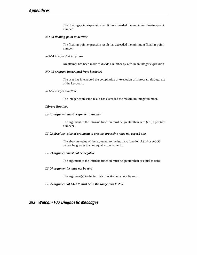
Appendices
The floating-point expression result has exceeded the maximum floating-pointnumber.
KO-03 floating-point underflow
The floating-point expression result has exceeded the minimum floating-pointnumber.
KO-04 integer divide by zero
An attempt has been made to divide a number by zero in an integer expression.
KO-05 program interrupted from keyboard
The user has interrupted the compilation or execution of a program through useof the keyboard.
KO-06 integer overflow
The integer expression result has exceeded the maximum integer number.
Library Routines
LI-01 argument must be greater than zero
The argument to the intrinsic function must be greater than zero (i.e., a positivenumber).
LI-02 absolute value of argument to arcsine, arccosine must not exceed one
The absolute value of the argument to the intrinsic function ASIN or ACOScannot be greater than or equal to the value 1.0.
LI-03 argument must not be negative
The argument to the intrinsic function must be greater than or equal to zero.
LI-04 argument(s) must not be zero
The argument(s) to the intrinsic function must not be zero.
LI-05 argument of CHAR must be in the range zero to 255
292 Watcom F77 Diagnostic Messages

Watcom F77 Diagnostic Messages
The argument to the intrinsic function CHAR must be in the range 0 to 255inclusive. CHAR returns the character represented by an 8-bit pattern.
LI-06 %s1 intrinsic function cannot be passed 2 complex arguments
The second argument to the intrinsic function CMPLX and DCMPLX cannot bea complex number.
LI-07 argument types must be the same for the %s1 intrinsic function
The second argument to the intrinsic function CMPLX or DCMPLX must be ofthe same type as the first argument. The second argument may only be usedwhen the first argument is of type INTEGER, REAL or DOUBLE PRECISION.
LI-08 expecting numeric argument, but %s1 argument was found
The argument to the intrinsic function, INT, REAL, DBLE, CMPLX, orDCMPLX was of type %s1 and a numeric argument was expected.
LI-09 length of ICHAR argument greater than one
The length of the argument to the intrinsic function ICHAR must be of typeCHARACTER and length of 1. ICHAR converts a character to its integerrepresentation.
LI-10 cannot pass %s1 as argument to intrinsic function
The item %s1 cannot be used as an argument to an intrinsic function. Onlyconstants, simple variables, array elements, and substrung array elements may beused as arguments.
LI-11 intrinsic function requires argument(s)
An attempt has been made to invoke an intrinsic function and no actualarguments were listed.
LI-12 %s1 argument type is invalid for this generic function
The type of the argument used in the generic intrinsic function is not correct.
LI-13 this intrinsic function cannot be passed as an argument
Watcom F77 Diagnostic Messages 293

Appendices
Only the specific name of the intrinsic function can be used as an actualargument. The generic name may not be used. When the generic and intrinsicnames are the same, use the INTRINSIC statement.
LI-14 expecting %s1 argument, but %s2 argument was found
An argument of type %s2 was passed to a function but an argument of type %s1was expected.
LI-15 intrinsic function was assigned wrong type
The declared type of an intrinsic function does not agree with the actual type.
LI-16 intrinsic function %s1 is not FORTRAN 77 standard
The specified intrinsic function is provided as an extension to the FORTRAN 77language.
LI-17 argument to ALLOCATED intrinsic function must be an allocatable array orcharacter*(*) variable
The argument to the intrinsic function ALLOCATED must be an allocatablearray or character*(*) variable.
LI-18 invalid argument to ISIZEOF intrinsic function
The argument to the intrinsic function ISIZEOF must be a user-defined structurename, a symbol name, or a constant.
Mixed Mode
MD-01 relational operator has a logical operand
The operands of a relational expression must either be both arithmetic or bothcharacter expressions. The operand indicated is a logical expression.
MD-02 mixing DOUBLE PRECISION and COMPLEX types is not FORTRAN 77 standard
The mixing of items of type DOUBLE PRECISION and COMPLEX in anexpression is an extension to the FORTRAN 77 language.
MD-03 operator not expecting %s1 operands
294 Watcom F77 Diagnostic Messages
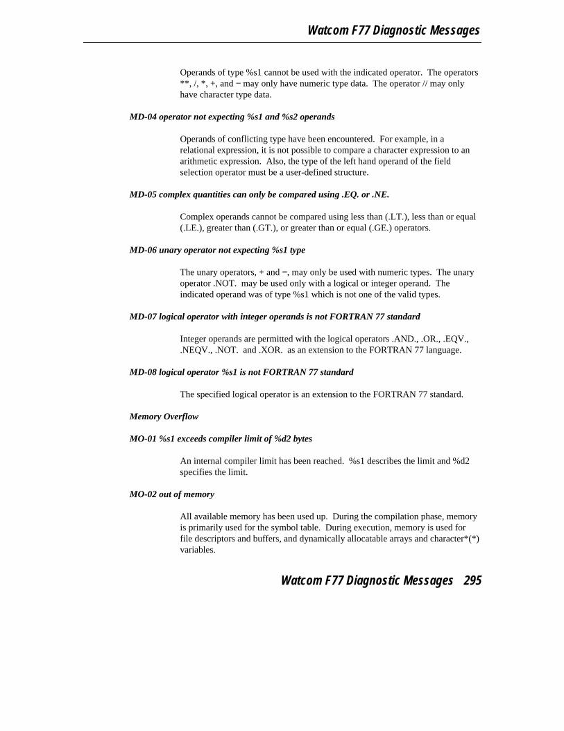
Watcom F77 Diagnostic Messages
Operands of type %s1 cannot be used with the indicated operator. The operators**, /, *, +, and − may only have numeric type data. The operator // may onlyhave character type data.
MD-04 operator not expecting %s1 and %s2 operands
Operands of conflicting type have been encountered. For example, in arelational expression, it is not possible to compare a character expression to anarithmetic expression. Also, the type of the left hand operand of the fieldselection operator must be a user-defined structure.
MD-05 complex quantities can only be compared using .EQ. or .NE.
Complex operands cannot be compared using less than (.LT.), less than or equal(.LE.), greater than (.GT.), or greater than or equal (.GE.) operators.
MD-06 unary operator not expecting %s1 type
The unary operators, + and −, may only be used with numeric types. The unaryoperator .NOT. may be used only with a logical or integer operand. Theindicated operand was of type %s1 which is not one of the valid types.
MD-07 logical operator with integer operands is not FORTRAN 77 standard
Integer operands are permitted with the logical operators .AND., .OR., .EQV.,.NEQV., .NOT. and .XOR. as an extension to the FORTRAN 77 language.
MD-08 logical operator %s1 is not FORTRAN 77 standard
The specified logical operator is an extension to the FORTRAN 77 standard.
Memory Overflow
MO-01 %s1 exceeds compiler limit of %d2 bytes
An internal compiler limit has been reached. %s1 describes the limit and %d2specifies the limit.
MO-02 out of memory
All available memory has been used up. During the compilation phase, memoryis primarily used for the symbol table. During execution, memory is used forfile descriptors and buffers, and dynamically allocatable arrays and character*(*)variables.
Watcom F77 Diagnostic Messages 295
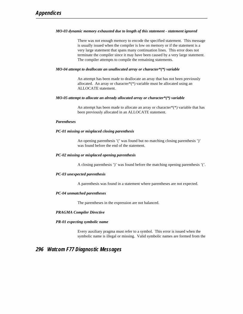
Appendices
MO-03 dynamic memory exhausted due to length of this statement - statement ignored
There was not enough memory to encode the specified statement. This messageis usually issued when the compiler is low on memory or if the statement is avery large statement that spans many continuation lines. This error does notterminate the compiler since it may have been caused by a very large statement.The compiler attempts to compile the remaining statements.
MO-04 attempt to deallocate an unallocated array or character*(*) variable
An attempt has been made to deallocate an array that has not been previouslyallocated. An array or character*(*) variable must be allocated using anALLOCATE statement.
MO-05 attempt to allocate an already allocated array or character*(*) variable
An attempt has been made to allocate an array or character*(*) variable that hasbeen previously allocated in an ALLOCATE statement.
Parentheses
PC-01 missing or misplaced closing parenthesis
An opening parenthesis ’(’ was found but no matching closing parenthesis ’)’was found before the end of the statement.
PC-02 missing or misplaced opening parenthesis
A closing parenthesis ’)’ was found before the matching opening parenthesis ’(’.
PC-03 unexpected parenthesis
A parenthesis was found in a statement where parentheses are not expected.
PC-04 unmatched parentheses
The parentheses in the expression are not balanced.
PRAGMA Compiler Directive
PR-01 expecting symbolic name
Every auxiliary pragma must refer to a symbol. This error is issued when thesymbolic name is illegal or missing. Valid symbolic names are formed from the
296 Watcom F77 Diagnostic Messages

Watcom F77 Diagnostic Messages
following characters: a dollar sign, an underscore, digits and any letter of thealphabet. The first character of a symbolic name must be alphabetic, a dollarsign, or an underscore.
PR-02 illegal size specified for VALUE attribute
The VALUE argument attribute of an auxiliary pragma contains in illegal lengthspecification. Valid length specifications are 1, 2, 4 and 8.
PR-03 illegal argument attribute
An illegal argument attribute was specified. Valid argument attributes areVALUE, REFERENCE, or DATA_REFERENCE.
PR-04 continuation line must contain a comment character in column 1
When continuing a line of an auxiliary pragma directive, the continued line mustend with a back-slash (’\’) character and the continuation line must begin with acomment character (’c’, ’C’ or ’*’) in column 1.
PR-05 expecting ’%s1’ near ’%s2’
A syntax error was found while processing a PRAGMA directive. %s1identifies the expected information and %s2 identifies where in the pragma theerror occurred.
PR-06 in-line byte sequence limit exceeded
The limit on the number of bytes of code that can be generated in-line using a anauxiliary pragma has been exceeded. The limit is 127 bytes.
PR-07 illegal hexadecimal data in byte sequence
An illegal hexadecimal constant was encountered while processing a in-line bytesequence of an auxiliary pragma. Valid hexadecimal constants in an in-line bytesequence must begin with the letter Z or z and followed by a string ofhexadecimal digits.
PR-08 symbol ’%s1’ in in-line assembly code cannot be resolved
The symbol %s1, referenced in an assembly language instruction in an auxiliarypragma, could not be resolved.
Watcom F77 Diagnostic Messages 297
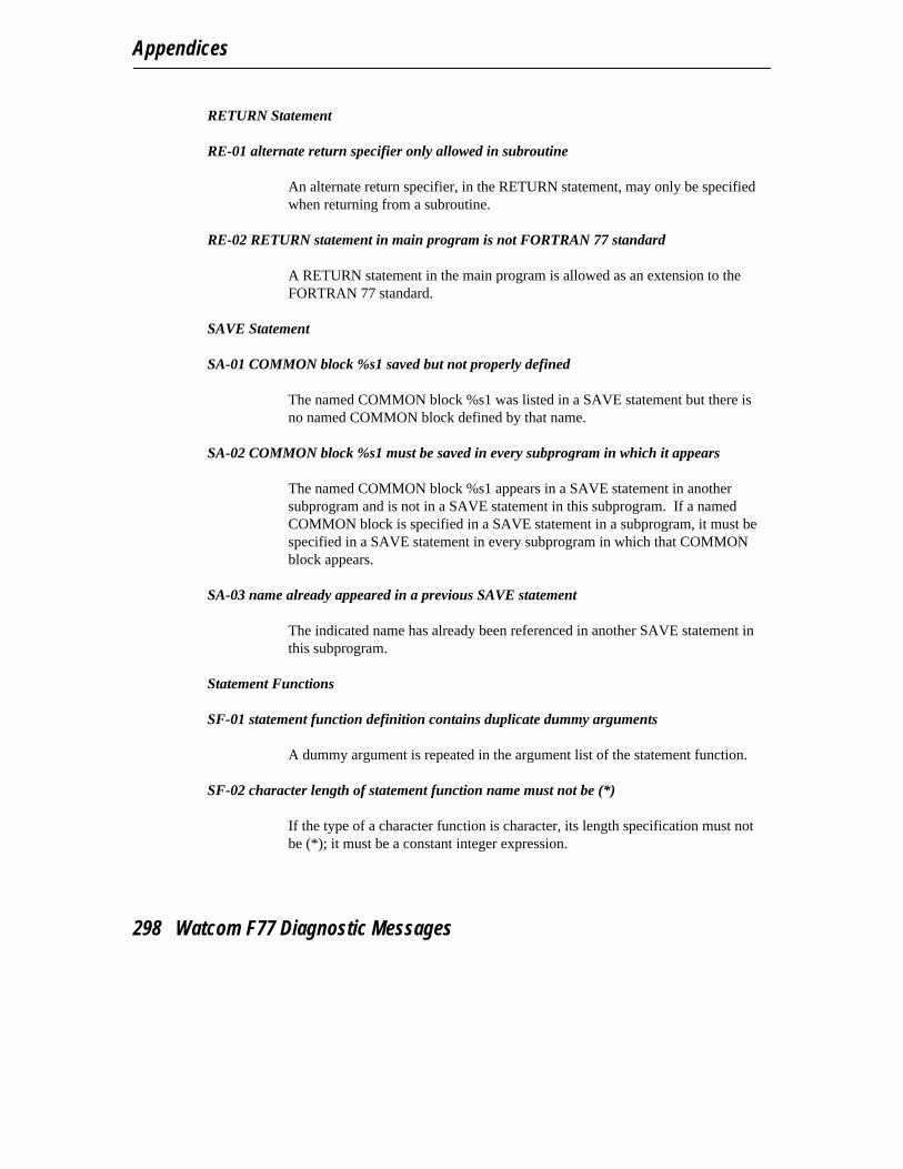
Appendices
RETURN Statement
RE-01 alternate return specifier only allowed in subroutine
An alternate return specifier, in the RETURN statement, may only be specifiedwhen returning from a subroutine.
RE-02 RETURN statement in main program is not FORTRAN 77 standard
A RETURN statement in the main program is allowed as an extension to theFORTRAN 77 standard.
SAVE Statement
SA-01 COMMON block %s1 saved but not properly defined
The named COMMON block %s1 was listed in a SAVE statement but there isno named COMMON block defined by that name.
SA-02 COMMON block %s1 must be saved in every subprogram in which it appears
The named COMMON block %s1 appears in a SAVE statement in anothersubprogram and is not in a SAVE statement in this subprogram. If a namedCOMMON block is specified in a SAVE statement in a subprogram, it must bespecified in a SAVE statement in every subprogram in which that COMMONblock appears.
SA-03 name already appeared in a previous SAVE statement
The indicated name has already been referenced in another SAVE statement inthis subprogram.
Statement Functions
SF-01 statement function definition contains duplicate dummy arguments
A dummy argument is repeated in the argument list of the statement function.
SF-02 character length of statement function name must not be (*)
If the type of a character function is character, its length specification must notbe (*); it must be a constant integer expression.
298 Watcom F77 Diagnostic Messages
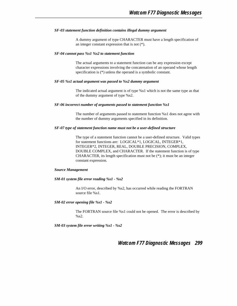
Watcom F77 Diagnostic Messages
SF-03 statement function definition contains illegal dummy argument
A dummy argument of type CHARACTER must have a length specification ofan integer constant expression that is not (*).
SF-04 cannot pass %s1 %s2 to statement function
The actual arguments to a statement function can be any expression exceptcharacter expressions involving the concatenation of an operand whose lengthspecification is (*) unless the operand is a symbolic constant.
SF-05 %s1 actual argument was passed to %s2 dummy argument
The indicated actual argument is of type %s1 which is not the same type as thatof the dummy argument of type %s2.
SF-06 incorrect number of arguments passed to statement function %s1
The number of arguments passed to statement function %s1 does not agree withthe number of dummy arguments specified in its definition.
SF-07 type of statement function name must not be a user-defined structure
The type of a statement function cannot be a user-defined structure. Valid typesfor statement functions are: LOGICAL*1, LOGICAL, INTEGER*1,INTEGER*2, INTEGER, REAL, DOUBLE PRECISION, COMPLEX,DOUBLE COMPLEX, and CHARACTER. If the statement function is of typeCHARACTER, its length specification must not be (*); it must be an integerconstant expression.
Source Management
SM-01 system file error reading %s1 - %s2
An I/O error, described by %s2, has occurred while reading the FORTRANsource file %s1.
SM-02 error opening file %s1 - %s2
The FORTRAN source file %s1 could not be opened. The error is described by%s2.
SM-03 system file error writing %s1 - %s2
Watcom F77 Diagnostic Messages 299
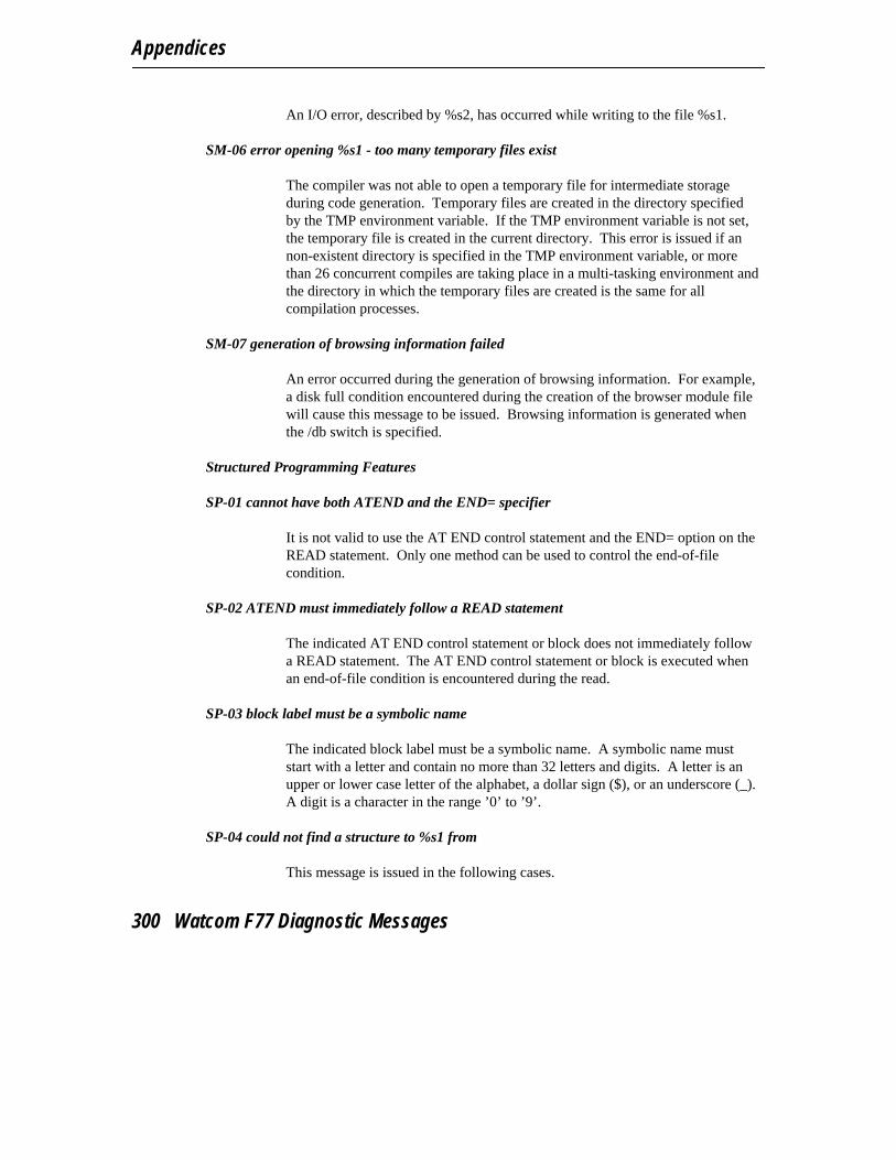
Appendices
An I/O error, described by %s2, has occurred while writing to the file %s1.
SM-06 error opening %s1 - too many temporary files exist
The compiler was not able to open a temporary file for intermediate storageduring code generation. Temporary files are created in the directory specifiedby the TMP environment variable. If the TMP environment variable is not set,the temporary file is created in the current directory. This error is issued if annon-existent directory is specified in the TMP environment variable, or morethan 26 concurrent compiles are taking place in a multi-tasking environment andthe directory in which the temporary files are created is the same for allcompilation processes.
SM-07 generation of browsing information failed
An error occurred during the generation of browsing information. For example,a disk full condition encountered during the creation of the browser module filewill cause this message to be issued. Browsing information is generated whenthe /db switch is specified.
Structured Programming Features
SP-01 cannot have both ATEND and the END= specifier
It is not valid to use the AT END control statement and the END= option on theREAD statement. Only one method can be used to control the end-of-filecondition.
SP-02 ATEND must immediately follow a READ statement
The indicated AT END control statement or block does not immediately followa READ statement. The AT END control statement or block is executed whenan end-of-file condition is encountered during the read.
SP-03 block label must be a symbolic name
The indicated block label must be a symbolic name. A symbolic name muststart with a letter and contain no more than 32 letters and digits. A letter is anupper or lower case letter of the alphabet, a dollar sign ($), or an underscore (_).A digit is a character in the range ’0’ to ’9’.
SP-04 could not find a structure to %s1 from
This message is issued in the following cases.
300 Watcom F77 Diagnostic Messages

Watcom F77 Diagnostic Messages
1. There is no control structure to QUIT from. The QUIT statement willtransfer control to the statement following the currently active controlstructure or return from a REMOTE BLOCK if no other controlstructures are active within the REMOTE BLOCK.
2. There is no control structure to EXIT from. The EXIT statement isused to exit a loop-processing structure such as DO, DO WHILE,WHILE and LOOP, to return from a REMOTE BLOCK regardless ofthe number of active control structures within the REMOTE BLOCK,or to transfer control from a GUESS or ADMIT block to thestatement following the ENDGUESS statement.
3. There is no active looping control structure from which a CYCLEstatement can be used. A CYCLE statement can only be used withina DO, DO WHILE, WHILE and LOOP control structure.
SP-05 REMOTE BLOCK is not allowed in the range of any control structure
An attempt has been made to define a REMOTE BLOCK inside a controlstructure. Control structures include IF, LOOP, WHILE, DO, SELECT andGUESS. When a REMOTE BLOCK definition is encountered during execution,control is transferred to the statement following the corresponding END BLOCKstatement.
SP-06 the SELECT statement must be followed immediately by a CASE statement
The statement immediately after the SELECT statement must be a CASEstatement. The SELECT statement allows one of a number of blocks of code(case blocks) to be selected for execution by means of an integer expression inthe SELECT statement.
SP-07 cases are overlapping
The case lists specified in the CASE statements in the SELECT control structureare in conflict. Each case list must specify a unique integer constant expressionor range.
SP-08 select structure requires at least one CASE statement
In the SELECT control structure, there must be at least one CASE statement.
SP-09 cannot branch to %d1 from outside control structure in line %d2
Watcom F77 Diagnostic Messages 301

Appendices
The statement in line %d2 passes control to the statement %d1 in a controlstructure. Control may only be passed out of a control structure or to anotherplace in that control structure. Control structures include DO, GUESS, IF,LOOP, SELECT, and WHILE.
SP-10 cannot branch to %d1 inside structure on line %d2
The statement attempts to pass control to statement %d1 in line %d2 which is ina control structure. Control may only be passed out of a control structure or toanother place in that control structure. Control structures include DO, GUESS,IF, LOOP, SELECT, and WHILE.
SP-11 low end of range exceeds the high end
The first number, the low end of the range, is greater than the second number,the high end of the range.
SP-12 default case block must follow all case blocks
The default case block in the SELECT control structure must be the last caseblock. A case block may not follow the default case block.
SP-13 attempt to branch out of a REMOTE BLOCK
An attempt has been made to transfer execution control out of a REMOTEBLOCK. A REMOTE BLOCK may only be terminated with the END BLOCKstatement. Execution of a REMOTE BLOCK is similar in concept to executionof a subroutine.
SP-14 attempt to EXECUTE undefined REMOTE BLOCK %s1
The REMOTE BLOCK %s1 referenced in the EXECUTE statement does notexist in the current program unit. A REMOTE BLOCK is local to the programunit in which it is defined and may not be referenced from another program unit.
SP-15 attempted to use REMOTE BLOCK recursively
An attempt was made to execute a REMOTE BLOCK which was already active.
SP-16 cannot RETURN from subprogram within a REMOTE BLOCK
An illegal attempt has been made to execute a RETURN statement within aREMOTE BLOCK in a subprogram.
302 Watcom F77 Diagnostic Messages
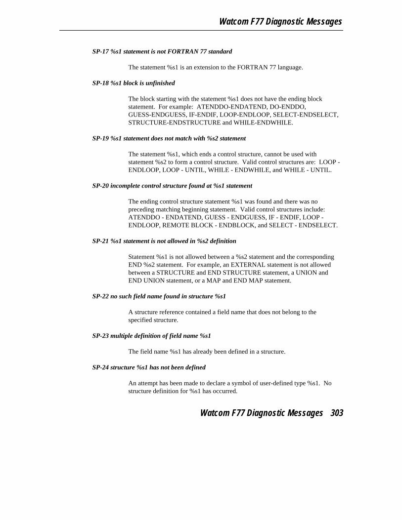
Watcom F77 Diagnostic Messages
SP-17 %s1 statement is not FORTRAN 77 standard
The statement %s1 is an extension to the FORTRAN 77 language.
SP-18 %s1 block is unfinished
The block starting with the statement %s1 does not have the ending blockstatement. For example: ATENDDO-ENDATEND, DO-ENDDO,GUESS-ENDGUESS, IF-ENDIF, LOOP-ENDLOOP, SELECT-ENDSELECT,STRUCTURE-ENDSTRUCTURE and WHILE-ENDWHILE.
SP-19 %s1 statement does not match with %s2 statement
The statement %s1, which ends a control structure, cannot be used withstatement %s2 to form a control structure. Valid control structures are: LOOP -ENDLOOP, LOOP - UNTIL, WHILE - ENDWHILE, and WHILE - UNTIL.
SP-20 incomplete control structure found at %s1 statement
The ending control structure statement %s1 was found and there was nopreceding matching beginning statement. Valid control structures include:ATENDDO - ENDATEND, GUESS - ENDGUESS, IF - ENDIF, LOOP -ENDLOOP, REMOTE BLOCK - ENDBLOCK, and SELECT - ENDSELECT.
SP-21 %s1 statement is not allowed in %s2 definition
Statement %s1 is not allowed between a %s2 statement and the correspondingEND %s2 statement. For example, an EXTERNAL statement is not allowedbetween a STRUCTURE and END STRUCTURE statement, a UNION andEND UNION statement, or a MAP and END MAP statement.
SP-22 no such field name found in structure %s1
A structure reference contained a field name that does not belong to thespecified structure.
SP-23 multiple definition of field name %s1
The field name %s1 has already been defined in a structure.
SP-24 structure %s1 has not been defined
An attempt has been made to declare a symbol of user-defined type %s1. Nostructure definition for %s1 has occurred.
Watcom F77 Diagnostic Messages 303

Appendices
SP-25 structure %s1 has already been defined
The specified structure has already been defined as a structure.
SP-26 structure %s1 must contain at least one field
Structures must contain at least one field definition.
SP-27 recursion detected in definition of structure %s1
Structure %s1 has been defined recursively. For example, it is illegal forstructure X to contain a field that is itself a structure named X.
SP-28 illegal use of structure %s1 containing union
Structures containing unions cannot be used in formatted I/O statements or datainitialized.
SP-29 allocatable arrays cannot be fields within structures
An allocatable array cannot appear as a field name within a structure definition.
SP-30 an integer conditional expression is not FORTRAN 77 standard
A conditional expression is the expression that is evaluated and checked todetermine a path of execution. A conditional expression can be found in an IFor WHILE statement. FORTRAN 77 requires that the conditional expression bea logical expression. As an extension, an integer expression is also allowed.When an integer expression is used, it is converted to a logical expression bycomparing the value of the integer expression to zero.
SP-31 %s1 statement must be used within %s2 definition
The statement identified by %s1 must appear within a definition identified by%s2.
Subprograms
SR-01 name can only appear in an EXTERNAL statement once
A function/subroutine name appears more than once in an EXTERNALstatement.
304 Watcom F77 Diagnostic Messages

Watcom F77 Diagnostic Messages
SR-02 character function %s1 may not be called since size was declared as (*)
In the declaration of the character function name, the length was defined to be(*). The (*) length specification is only allowed for external functions, dummyarguments or symbolic character constants.
SR-03 %s1 can only be used an an argument to a subroutine
The specified class of an argument must only be passed to a subroutine. Forexample, an alternate return specifier is illegal as a subscript or an argument to afunction.
SR-04 name cannot appear in both an INTRINSIC and EXTERNAL statement
The same name appears in an INTRINSIC statement and in an EXTERNALstatement.
SR-05 expecting a subroutine name
The subroutine named in the CALL statement does not define a subroutine. Asubroutine is declared in a SUBROUTINE statement.
SR-06 %s1 statement not allowed in main program
The main program can contain any statements except a FUNCTION,SUBROUTINE, BLOCK DATA, or ENTRY statement. A SAVE statement isallowed but has no effect in the main program. A RETURN statement in themain program is an extension to the FORTRAN 77 language.
SR-07 not an intrinsic FUNCTION name
A name in the INTRINSIC statement is not an intrinsic function name. Refer tothe Language Reference for a complete list of the intrinsic functions.
SR-08 name can only appear in an INTRINSIC statement once
An intrinsic function name appears more than once in the intrinsic function list.
SR-09 subprogram recursion detected
An attempt has been made to recursively invoke a subprogram, that is, to invokean already active subprogram.
Watcom F77 Diagnostic Messages 305

Appendices
SR-10 two main program units in the same file
There are two places in the program that signify the start of a main program.The PROGRAM statement or the first statement that is not enclosed by aPROGRAM, FUNCTION, SUBROUTINE or BLOCK DATA statementspecifies the main program start.
SR-11 only one unnamed %s1 is allowed in an executable program
There may only be one unnamed BLOCK DATA subprogram or main programin an executable program.
SR-12 function referenced as a subroutine
An attempt has been made to invoke a function using the CALL statement.
Subscripts and Substrings
SS-01 substringing of function or statement function return value is not FORTRAN 77standard
The character value returned from a CHARACTER function or statementfunction cannot be substrung. Only character variable names and array elementnames may be substrung.
SS-02 substringing valid only for character variables and array elements
An attempt has been made to substring a name that is not defined to be of typeCHARACTER and is neither a variable nor an array element.
SS-03 subscript expression out of range %s1 does not exist
An attempt has been made to reference an element in an array that is out ofbounds of the declared array size. The array element %s1 does not exist.
SS-04 substring expression (%d1:%d2) is out of range
An expression in the substring is larger than the string length or less than thevalue 1. The substring expression must be one in which
1 <= %d1 <= %d2 <= len
306 Watcom F77 Diagnostic Messages

Watcom F77 Diagnostic Messages
Statements and Statement Numbers
ST-01 statement number %d1 has already been defined in line %d2
The two statements, in line %d2 and the current line, in the current program unithave the same statement label number, namely %d1.
ST-02 statement function definition appears after first executable statement
There is a statement function definition after the first executable statement in theprogram unit. Statement function definitions must follow specificationstatements and precede executable statements. Check that the statement functionname is not an undeclared array name.
ST-03 %s1 statement must not be branched to but was in line %d2
Line %d2 passed execution control down to the statement %s1. Thespecification statements, ADMIT, AT END, BLOCK DATA, CASE, ELSE,ELSE IF, END AT END, END BLOCK, END DO, END LOOP, ENDSELECT, END WHILE, ENTRY, FORMAT, FUNCTION, OTHERWISE,PROGRAM, QUIT, REMOTE BLOCK, SAVE, SUBROUTINE, and UNTILstatements may not have control of execution transferred to it.
ST-04 branch to statement %d1 in line %d2 not allowed
An attempt has been made to pass execution control up to the statement labelled%d1 in line %d2. The specification statements, ADMIT, AT END, BLOCKDATA, CASE, ELSE, ELSE IF, END AT END, END BLOCK, END DO, ENDLOOP, END SELECT, END WHILE, ENTRY, FORMAT, FUNCTION,OTHERWISE, PROGRAM, QUIT, REMOTE BLOCK, SAVE,SUBROUTINE, and UNTIL statements may not have control of executiontransferred to it.
ST-05 specification statement must appear before %s1 is initialized
The variable %s1 has been initialized in a specification statement. A COMMONor EQUIVALENCE statement then references the variable. The COMMON orEQUIVALENCE statement must appear before the item can be initialized. Usethe DATA statement to initialize data in this case.
ST-06 statement %d1 was referenced as a FORMAT statement in line %d2
The statement in line %d2 references statement label %d1 as a FORMATstatement. The statement at that label is not a FORMAT statement.
Watcom F77 Diagnostic Messages 307

Appendices
ST-07 IMPLICIT statement appears too late
The current IMPLICIT statement is out of order. The IMPLICIT statement maybe interspersed with the PARAMETER statement but must appear before otherspecification statements.
ST-08 this statement will never be executed due to the preceding branch
Because execution control will always be passed around the indicated statement,the statement will never be executed.
ST-09 expecting statement number
The keyword GOTO or ASSIGN has been detected and the next part of thestatement was not a statement number as was expected.
ST-10 statement number %d1 was not used as a FORMAT statement in line %d2
The statement at line %d2 with statement number %d1 is not a FORMATstatement but the current statement uses statement number %d1 as if it labelled aFORMAT statement.
ST-11 specification statement appears too late
The indicated specification statement appears after a statement functiondefinition or an executable statement. All specification statements must appearbefore these types of statements.
ST-12 %s1 statement not allowed after %s2 statement
The statement %s1 cannot be the object of a %s2 statement. %s2 represents alogical IF or WHILE statement. These statements include: specificationstatements, ADMIT, AT END, CASE, DO, ELSE, ELSE IF END, END ATEND, END BLOCK, END DO, END GUESS, ENDIF, END LOOP, ENDSELECT, END WHILE, ENTRY, FORMAT, FUNCTION, GUESS, logical IF,block IF, LOOP, OTHERWISE, PROGRAM, REMOTE BLOCK, SAVE,SELECT, SUBROUTINE, UNTIL, and WHILE.
ST-13 statement number must be 99999 or less
The statement label number specified in the indicated statement has more than 5digits.
308 Watcom F77 Diagnostic Messages

Watcom F77 Diagnostic Messages
ST-14 statement number cannot be zero
The statement label number specified in the indicated statement is zero.Statement label numbers must be greater than 0 and less than or equal to 99999.
ST-15 this statement could branch to itself
The indicated statement refers to a statement label number which appears on thestatement itself and therefore could branch to itself, creating an endless loop.
ST-16 missing statement number %d1 - used in line %d2
A statement with the statement label number %d1 does not exist in the currentprogram unit. The statement label number is referenced in line %d2 of theprogram unit.
ST-17 undecodeable statement or misspelled word %s1
The statement cannot be identified as an assignment statement or any other typeof FORTRAN statement. The first word of a FORTRAN statement must be astatement keyword or the statement must be an assignment statement.
ST-18 statement %d1 will never be executed due to the preceding branch
The statement with the statement label number of %d1 will never be executedbecause the preceding statement will always pass execution control around thestatement and no other reference is made to the statement label.
ST-19 expecting keyword or symbolic name
The first character of a statement is not an alphabetic. The first word of astatement must be a statement keyword or a symbolic name. Symbolic namesmust start with a letter (upper case or lower case), a dollar sign ($) or anunderscore (_).
ST-20 number in %s1 statement is longer than 5 digits
The number in the PAUSE or STOP statement is longer than 5 digits.
ST-21 position of DATA statement is not FORTRAN 77 standard
The FORTRAN 77 standard requires DATA statements to appear after allspecification statements. As an extension to the standard, Watcom FORTRAN77 allows DATA statements to appear before specification statements. Note that
Watcom F77 Diagnostic Messages 309
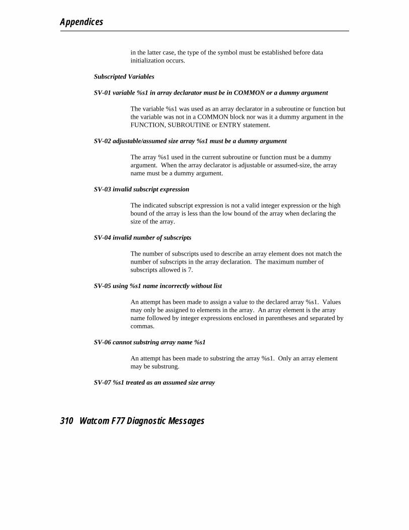
Appendices
in the latter case, the type of the symbol must be established before datainitialization occurs.
Subscripted Variables
SV-01 variable %s1 in array declarator must be in COMMON or a dummy argument
The variable %s1 was used as an array declarator in a subroutine or function butthe variable was not in a COMMON block nor was it a dummy argument in theFUNCTION, SUBROUTINE or ENTRY statement.
SV-02 adjustable/assumed size array %s1 must be a dummy argument
The array %s1 used in the current subroutine or function must be a dummyargument. When the array declarator is adjustable or assumed-size, the arrayname must be a dummy argument.
SV-03 invalid subscript expression
The indicated subscript expression is not a valid integer expression or the highbound of the array is less than the low bound of the array when declaring thesize of the array.
SV-04 invalid number of subscripts
The number of subscripts used to describe an array element does not match thenumber of subscripts in the array declaration. The maximum number ofsubscripts allowed is 7.
SV-05 using %s1 name incorrectly without list
An attempt has been made to assign a value to the declared array %s1. Valuesmay only be assigned to elements in the array. An array element is the arrayname followed by integer expressions enclosed in parentheses and separated bycommas.
SV-06 cannot substring array name %s1
An attempt has been made to substring the array %s1. Only an array elementmay be substrung.
SV-07 %s1 treated as an assumed size array
310 Watcom F77 Diagnostic Messages
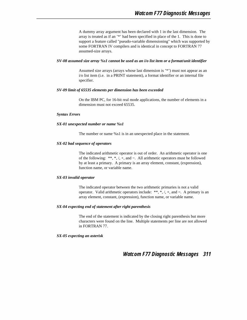
Watcom F77 Diagnostic Messages
A dummy array argument has been declared with 1 in the last dimension. Thearray is treated as if an ’*’ had been specified in place of the 1. This is done tosupport a feature called "pseudo-variable dimensioning" which was supported bysome FORTRAN IV compilers and is identical in concept to FORTRAN 77assumed-size arrays.
SV-08 assumed size array %s1 cannot be used as an i/o list item or a format/unit identifier
Assumed size arrays (arrays whose last dimension is ’*’) must not appear as ani/o list item (i.e. in a PRINT statement), a format identifier or an internal filespecifier.
SV-09 limit of 65535 elements per dimension has been exceeded
On the IBM PC, for 16-bit real mode applications, the number of elements in adimension must not exceed 65535.
Syntax Errors
SX-01 unexpected number or name %s1
The number or name %s1 is in an unexpected place in the statement.
SX-02 bad sequence of operators
The indicated arithmetic operator is out of order. An arithmetic operator is oneof the following: **, *, /, +, and −. All arithmetic operators must be followedby at least a primary. A primary is an array element, constant, (expression),function name, or variable name.
SX-03 invalid operator
The indicated operator between the two arithmetic primaries is not a validoperator. Valid arithmetic operators include: **, *, /, +, and −. A primary is anarray element, constant, (expression), function name, or variable name.
SX-04 expecting end of statement after right parenthesis
The end of the statement is indicated by the closing right parenthesis but morecharacters were found on the line. Multiple statements per line are not allowedin FORTRAN 77.
SX-05 expecting an asterisk
Watcom F77 Diagnostic Messages 311

Appendices
The next character of the statement should be an asterisk but another characterwas found instead.
SX-06 expecting colon
A colon (:) was expecting but not found. For example, the colon separating thelow and high bounds of a character substring was not found.
SX-07 expecting colon or end of statement
On a control statement, a word was found at the end of the statement that cannotbe related to the statement. The last word on several of the control statementsmay be a block label. All block labels must be preceded by a colon (:).
SX-08 missing comma
A comma was expected and is missing. There must be a comma after thestatement keyword AT END when a statement follows. A comma must occurbetween the two statement labels in the GO TO statement. A comma must occurbetween the expressions in the DO statement. A comma must occur between thenames listed in the DATA statement and specification statements. A commamust occur between the specifiers in I/O statements.
SX-09 expecting end of statement
The end of the statement was expected but more words were found on the lineand cannot be associated to the statement. FORTRAN 77 only allows for onestatement per line.
SX-10 expecting integer variable
The name indicated in the statement must be of type INTEGER but is not.
SX-11 expecting %s1 name
A name with the characteristic %s1 was expected at the indicated place in thestatement but is missing.
SX-12 expecting an integer
The length specifier, as in the IMPLICIT statement, must be an integer constantor an integer constant expression. The repeat specifier of the value to beassigned to the variables, as in the DATA statement, must be an integer constantor an integer constant expression.
312 Watcom F77 Diagnostic Messages
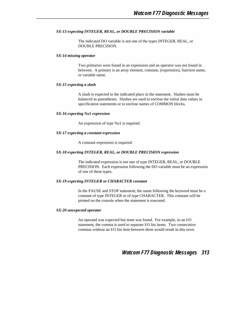
Watcom F77 Diagnostic Messages
SX-13 expecting INTEGER, REAL, or DOUBLE PRECISION variable
The indicated DO variable is not one of the types INTEGER, REAL, orDOUBLE PRECISION.
SX-14 missing operator
Two primaries were found in an expression and an operator was not found inbetween. A primary is an array element, constant, (expression), function name,or variable name.
SX-15 expecting a slash
A slash is expected in the indicated place in the statement. Slashes must bebalanced as parentheses. Slashes are used to enclose the initial data values inspecification statements or to enclose names of COMMON blocks.
SX-16 expecting %s1 expression
An expression of type %s1 is required.
SX-17 expecting a constant expression
A constant expression is required.
SX-18 expecting INTEGER, REAL, or DOUBLE PRECISION expression
The indicated expression is not one of type INTEGER, REAL, or DOUBLEPRECISION. Each expression following the DO variable must be an expressionof one of these types.
SX-19 expecting INTEGER or CHARACTER constant
In the PAUSE and STOP statement, the name following the keyword must be aconstant of type INTEGER or of type CHARACTER. This constant will beprinted on the console when the statement is executed.
SX-20 unexpected operator
An operand was expected but none was found. For example, in an I/Ostatement, the comma is used to separate I/O list items. Two consecutivecommas without an I/O list item between them would result in this error.
Watcom F77 Diagnostic Messages 313
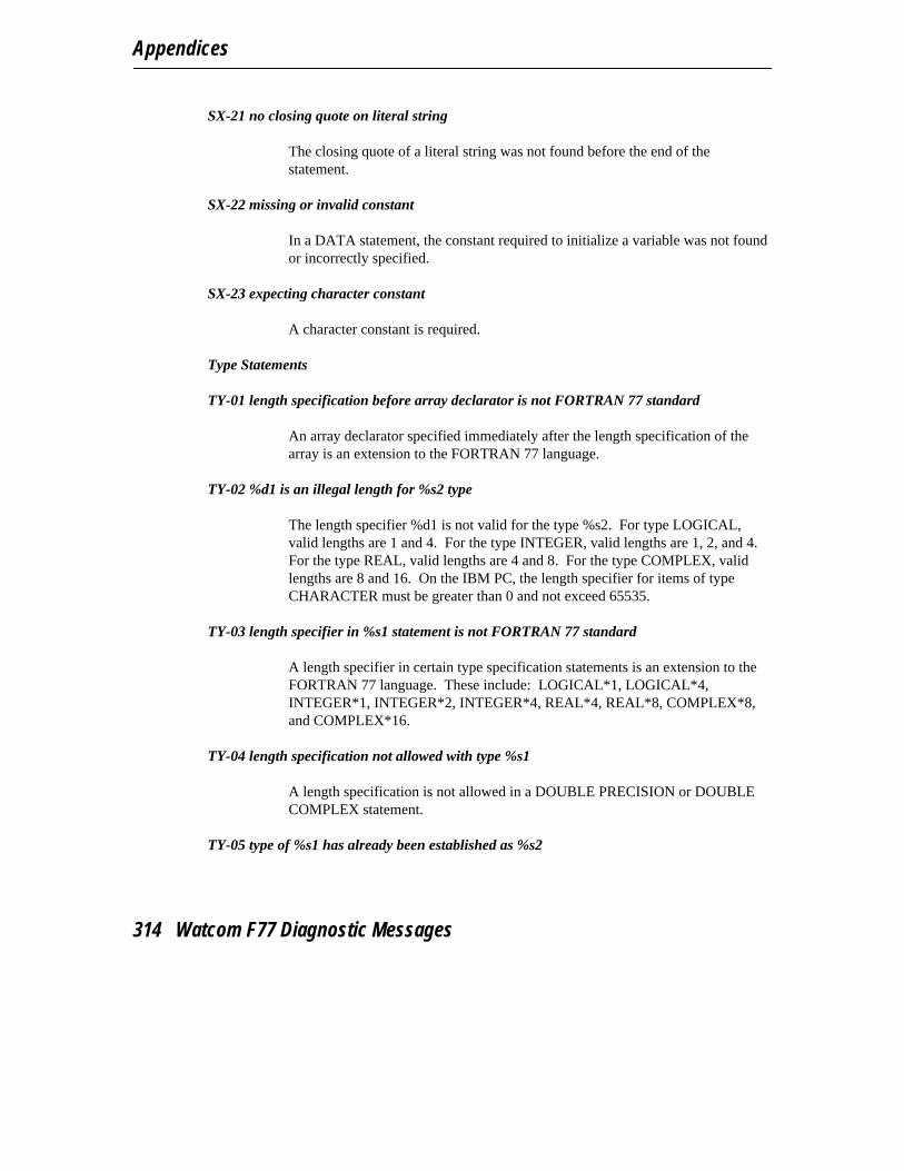
Appendices
SX-21 no closing quote on literal string
The closing quote of a literal string was not found before the end of thestatement.
SX-22 missing or invalid constant
In a DATA statement, the constant required to initialize a variable was not foundor incorrectly specified.
SX-23 expecting character constant
A character constant is required.
Type Statements
TY-01 length specification before array declarator is not FORTRAN 77 standard
An array declarator specified immediately after the length specification of thearray is an extension to the FORTRAN 77 language.
TY-02 %d1 is an illegal length for %s2 type
The length specifier %d1 is not valid for the type %s2. For type LOGICAL,valid lengths are 1 and 4. For the type INTEGER, valid lengths are 1, 2, and 4.For the type REAL, valid lengths are 4 and 8. For the type COMPLEX, validlengths are 8 and 16. On the IBM PC, the length specifier for items of typeCHARACTER must be greater than 0 and not exceed 65535.
TY-03 length specifier in %s1 statement is not FORTRAN 77 standard
A length specifier in certain type specification statements is an extension to theFORTRAN 77 language. These include: LOGICAL*1, LOGICAL*4,INTEGER*1, INTEGER*2, INTEGER*4, REAL*4, REAL*8, COMPLEX*8,and COMPLEX*16.
TY-04 length specification not allowed with type %s1
A length specification is not allowed in a DOUBLE PRECISION or DOUBLECOMPLEX statement.
TY-05 type of %s1 has already been established as %s2
314 Watcom F77 Diagnostic Messages

Watcom F77 Diagnostic Messages
The indicated name %s1 has already been declared to have a different type,namely %s2. The name %s1 cannot be used in this specification statement.
TY-06 type of %s1 has not been declared
The indicated name %s1 has not been declared. This message is only issuedwhen the IMPLICIT NONE specification statement is used.
TY-07 %s1 of type %s2 is illegal in %s3 statement
The symbol %s1 with type %s2 cannot be used in statement %s3. For example,a symbol of type STRUCTURE cannot be used in a PARAMETER statement.
Variable Names
VA-01 illegal use of %s1 name %s2 in %s3 statement
The name %s2 has been defined as %s1 and cannot be used as a name in thestatement %s3.
VA-02 symbolic name %s1 is longer than 6 characters
Symbolic names greater than 6 characters is an extension to the FORTRAN 77language. The maximum length is 32 characters.
VA-03 %s1 has already been defined as a %s2
The name %s1 has been previously defined as a %s2 in another statement andcannot be redefined as specified in the indicated statement.
VA-04 %s1 %s2 has not been defined
The name %s2 has been referenced to be a %s1 but has not been defined as suchin the program unit.
VA-05 %s1 is an unreferenced symbol
The name %s1 has been defined but not referenced.
VA-06 %s1 already belongs to this NAMELIST group
The name %s1 can only appear in a NAMELIST group once. However, a namecan belong to multiple NAMELIST groups.
Watcom F77 Diagnostic Messages 315
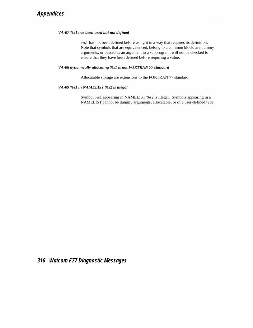
Appendices
VA-07 %s1 has been used but not defined
%s1 has not been defined before using it in a way that requires its definition.Note that symbols that are equivalenced, belong to a common block, are dummyarguments, or passed as an argument to a subprogram, will not be checked toensure that they have been defined before requiring a value.
VA-08 dynamically allocating %s1 is not FORTRAN 77 standard
Allocatable storage are extensions to the FORTRAN 77 standard.
VA-09 %s1 in NAMELIST %s2 is illegal
Symbol %s1 appearing in NAMELIST %s2 is illegal. Symbols appearing in aNAMELIST cannot be dummy arguments, allocatable, or of a user-defined type.
316 Watcom F77 Diagnostic Messages

Index
3 B
__386__ 12 BACKSPACE 55BD option 11BD-01 267BD-02 267big code model 127, 187Abig data model 128, 188BINNT directory 256BINP directory 256
aborts (pragma) 172, 237 BINW directory 256ACCESS= 51 BIOS call 165, 230ACTION= 58, 73 BLOCKSIZE= 54, 57addressing arguments 139, 203 BM option 11alias name (pragma) 150, 214 BOUNDS option 11alias names buffer size 57
__cdecl 152, 216 BW option 11__pascal 152, 216__stdcall 216__syscall 216
ALIGN option 10 CAR-01 267AR-02 267AR-12 267argument list (pragma) 157, 222 callback functions 157arguments 79, 93 calling conventions 131, 193
passing by data reference 159, 224 calling information (pragma) 154, 219passing by reference 159, 224 calling subprogramspassing by value 159, 224 far 154, 219removing from the stack 166, 231 near 154, 219
arguments on the stack 164, 229 CARRIAGECONTROL= 54, 56assembler subprograms CC option 11
subroutine FINTR 82 CC-01 268AUTOEXEC.BAT 31 CC-02 268AUTOMATIC option 10 CC-03 268AUX 60 CC-04 268auxiliary pragma 149, 213 CC-05 268
CC-06 268CC-07 268CC-08 268CC-09 269
317

Index
__cdecl 152, 216, 221 compiler 29__cdecl alias name 152, 216 compiler directivesCHARACTER data type 113 define 12, 46CHINESE option 11 eject 44class else 48
CODE 130, 136, 191, 198 elseifdef 48FAR_DATA 130, 136, 191, 198 elseifndef 48
CLOCK$ 62 endif 47CLOSE 63, 77 ifdef 47CM-01 269 ifndef 47CM-02 269 include 44CM-03 269 pragma 46CM-04 269 undefine 46CM-05 269 compiler options 5CM-06 269 compiler options summary 5CN-01 270 compilingCN-02 270 command line format 29CN-03 270 COMPLEX data type 113CN-04 270 COMPLEX*16 data type 113CN-05 270 COMPLEX*8 data type 113CO-01 270 CON 60, 62CO-02 270 Win32 73CO-03 270 conditional compilation 12, 43CO-04 271 CONFIG.SYS 31CO-05 271 connection precedence 67CO-06 271 console device 73CO-07 271 CP-01 271CO-08 271 CP-02 272CODE class 130, 136, 191, 198 CP-03 272code generation CP-04 272
memory requirements 258 CP-05 272code models CP-06 272
big 127, 187 CP-07 272small 127, 187 CP-08 272
CODE option 11 CP-09 273COM1 60, 62 CP-10 273COM2 60, 62 CP-11 273COM3 62 CP-12 273COM4 62 CP-13 273command line 79, 93 Ctrl/Break 87command line format 29 CV-01 273compact memory model 188 CV-02 273COMPAT 58compile time 259
318

Index
traceback 12debugging macroD __debug__ 49-50debugging statements 49default libraries
using pragmas 148, 212D in column 1 49default memory model 20, 21D1 option 11default options 8D2 option 11default windowingDA-01 274
dwfDeleteOnClose 102DA-02 274dwfSetAboutDlg 102DA-03 274dwfSetAppTitle 103DA-04 274dwfSetConTitle 104DA-05 274dwfShutDown 105DA-06 274dwfYield 106DA-07 274
defaultsDA-08 274file name 64, 76DA-10 275record access 76DA-12 275record length 76data modelsrecord type 76big 128, 188
DEFINE compiler directive 46huge 128DEFINE=<macro> option 12small 128, 188DENYNONE 58data typesDENYRD 58CHARACTER 113DENYRW 58COMPLEX 113DENYWR 58COMPLEX*16 113DEPENDENCY option 12COMPLEX*8 113descriptor option 13, 134, 197DOUBLE PRECISION 111deviceINTEGER 110
AUX 60INTEGER*1 110CLOCK$ 62INTEGER*2 110COM1 60, 62INTEGER*4 110COM2 60, 62LOGICAL 110COM3 62LOGICAL*1 109COM4 62LOGICAL*4 110CON 60, 62REAL 110console 73REAL*4 110KBD$ 62REAL*8 111LPT1 60, 62DEBUG option 12LPT2 60, 62debuggingLPT3 60, 62bounds check 11-12MOUSE$ 62d1 11NUL 60, 62d2 12POINTER$ 62
319
Index
printer 75 EJECT compiler directive 44PRN 60, 62 ELSE compiler directive 48SCREEN$ 62 ELSEIFDEF compiler directive 48serial 75 ELSEIFNDEF compiler directive 48
device names 60, 62 emu87.lib 41diagnostic messages EN-01 277
language 262 END= 74diagnostics ENDIF compiler directive 47
error 33 English diagnostic messages 262warning 33 environment stringWatcom F77 32 # 30
DISK option 13 = substitute 30DLL applications 11, 27 environment variable 64DM-01 275 environment variablesDO-01 275 FINCLUDE 18, 45, 79-81, 85-86, 88-94,DO-02 275 97-100, 253DO-03 275 LIB 253DO-04 275 LIBDOS 254DO-05 276 LIBOS2 254DO-06 276 LIBPHAR 254-255DO-07 276 LIBWIN 254DOS subdirectory 37 NO87 41, 255DOSCALLS.LIB 254 PATH 45, 253, 256DOSPML.LIB 39 TMP 257DOSPMM.LIB 39 use 253DOUBLE PRECISION data type 111 WATCOM 253-255, 257drive name 59 WCGMEMORY 258-259DT=<size> option 13 WCL 257-258dwfDeleteOnClose function 102 WCL386 258dwfSetAboutDlg function 102 WD 259-260dwfSetAppTitle function 103 WDW 260dwfSetConTitle function 104 WFC 30, 32, 260-261dwfShutDown function 105 WFC386 30, 261dwfYield function 106 WFL 261-262dynamic link library applications 11, 27 WFL386 262
WLANG 262-263EQ-01 277EQ-02 277EQ-03 277EEQ-04 277EQ-05 277error file
EC-01 276 .ERR 32EC-02 276 ERROR message 265
320
Index
ERRORFILE option 13 file nameEV-01 278 case sensitivity 60EV-02 278 default 64, 76EV-03 278 file naming 51EV-04 278 file sharing 58EV-05 278 FILE= 70, 73, 75EV-06 278 filename 59EX-01 278 FILESIZE 81EX-02 278 FINCLUDE environment variable 18, 45, 79-81,EX-03 279 85-86, 88-94, 97-100, 253execute a program 89 FINTR subroutine 82exiting with return code 79 FIXED 56EXPLICIT option 13 FIXED record type 56export (pragma) 156-157, 222 flat memory model 188exporting symbols in dynamic link libraries 156, flat model
222 libraries 38, 190extension 59 float 154EXTENSION message 265 floating-pointEXTENSIONS option 14 consistency of options 15-16EY-01 279 option 15EY-02 279 FLUSHUNIT function 84EY-03 279 FM-01 279EZ option 14 FM-02 279
FM-03 279FM-04 279FM-05 280FM-06 280FFM-07 280FM-08 280FM-09 280
far (pragma) 154, 219 FM-10 280far call 127, 187 FM-11 280far16 221 FM-12 281far16 (pragma) 219 FM-13 281FAR_DATA class 130, 136, 191, 198 FM-14 281FAT file system 59 FM-15 281FDIV bug 17 FM-16 281FEXIT subroutine 79 FM-17 281FGETCMD function 79 FM-18 281FGETENV function 80 FM-19 281file connection 63 FM-20 281file defaults 76 FM-21 282file designation 59 FM-22 282file handling 51 FNEXTRECL function 85
321

Index
FO=<obj_default> option 14 __GROFORM= 52 stack growing 26FORMAT option 14 GROWHANDLES function 93FORMATTED 55 GSFLOATS option 17formatted record 52FORTRAN 77 libraries
flat 38huge 38 Hin-line 80x87 instructions 38large 38medium 38
HC option 18small 38HD option 18FORTRAN librariesheader fileflat 190
including 35small 190searching 44FP2 option 16
HO-01 282FP3 option 16HO-02 282FP5 option 16HPFS file system 59, 61FP6 option 16huge data model 128FPC option 15huge memory model 128FPD option 17huge modelFPI option 15
libraries 38FPI87 option 15HW option 18__fpi__ 12
FPR option 17FSFLOATS option 17FSIGNAL function 87 IFSPAWN function 88FSYSTEM function 89FTRACEBACK subroutine 90
__i86__ 12IARGC function 93IF 97G IF-01 283IF-02 283IFDEF compiler directive 47IFNDEF compiler directive 47general protection fault 27IGETARG function 93GETDAT subroutine 91IL-01 283GETTIM subroutine 92IL-02 283GO-01 282IL-03 284GO-02 282IL-04 284GO-03 282IL-05 284GPF 27
322

Index
IL-06 284 IO-01 286IL-07 284 IO-02 286IL-08 284 IO-03 287IL-09 284 IO-04 287IL-10 284 IO-05 287IL-11 285 IO-06 287IL-12 285 IO-07 287IL-13 285 IO-08 287IL-14 285 IO-09 287IL-15 285 IO-10 288IL-16 285 IO-11 288IL-17 285 IO-12 288IL-18 286 IO-13 288IM-01 286 IO-14 288IM-02 286 IO-15 288IM-03 286 IO-16 288IM-04 286 IO-17 288IM-05 286 IO-18 289IMPLICIT NONE 14 IO-19 289in-line 80x87 floating-point instructions 155 IO-20 289in-line 80x87 instructions IO-21 289
libraries 38 IO-22 289in-line assembly IO-23 289
in pragmas 154, 219 IO-24 289in-line assembly language instructions IO-25 290
using mnemonics 155, 221 IO-26 290in-line subprograms 155, 220 IO-27 290in-line subprograms (pragma) 165, 230 IO-28 290INCLIST option 18 IO-29 290INCLUDE 44-45 IO-30 290
directive 35 IO-31 290header file 35 IO-32 291source file 35 IO-33 291
INCLUDE compiler directive 44 IO-34 291include file IO-35 291
searching 44 IO-36 291INCPATH option 18, 45 IO-37 291increased precision 28 IO-38 291INQUIRE 63, 70, 72 IOSTAT= 74INTEGER data type 110 IPROMOTE option 18INTEGER*1 data type 110INTEGER*2 data type 110INTEGER*4 data type 110invoking Watcom FORTRAN 77 29
323
Index
LI-11 293LI-12 293J LI-13 293LI-14 294LI-15 294LI-16 294Japanese diagnostic messages 262LI-17 294JAPANESE option 19LI-18 294LIB environment variable 253LIBDOS environment variable 254LIBINFO option 19KLIBOS2 environment variable 254LIBPHAR environment variable 254-255library path 257LIBWIN environment variable 254KBD$ 62LIST option 20KO-01 291loadds (pragma) 156, 221KO-02 291loading DS before calling a subprogram 156, 221KO-03 292loading DS in prologue sequence of a subprogramKO-04 292
156, 222KO-05 292LOGICAL data type 110KO-06 292logical file name 69KOREAN option 19
device remapping 72display 73extended file names 70
LOGICAL*1 data type 109LLOGICAL*4 data type 110LONGJMP subroutine 97LPT1 60, 62
language 262 LPT2 60, 62large memory model 128, 188 LPT3 60, 62large model
libraries 38LFWITHFF option 19LI-01 292 MLI-02 292LI-03 292LI-04 292
macros 12LI-05 292predefined 12LI-06 293
MANGLE option 20LI-07 293math coprocessor 41LI-08 293
option 15LI-09 293math error functions 94LI-10 293
324
Index
MC option 20MD-01 294 NMD-02 294MD-03 294MD-04 295MD-05 295 NAME= 72MD-06 295 near (pragma) 154, 219MD-07 295 near call 127, 187MD-08 295 NETWARE subdirectory 37medium memory model 128, 188 no8087 (pragma) 167, 233medium model NO87 environment variable 41, 255
libraries 38 NT subdirectory 37memory layout 130, 135, 190, 198 NUL 60, 62memory model 31 numeric data processor 41memory models option 15
16-bit 12732-bit 187compact 188flat 188-189 Ohuge 128large 128, 188libraries 129, 190medium 128, 188 OB option 21mixed 129, 189 OBP option 21small 188 OC option 21
MF option 20 OD option 22MH option 21 ODO option 22mixed memory model 129, 189 OF option 22ML option 21 OH option 23MM option 21 OI option 23MO-01 295 OK option 23MO-02 295 OL option 23MO-03 296 OL+ option 23MO-04 296 OM option 23MO-05 296 ON option 23modify exact (pragma) 177, 243-244 OP option 24modify nomemory (pragma) 173, 175, 238, 241 OPEN 51-58, 63, 67, 69-70, 72-76modify reg_set (pragma) 183, 249 options 5MOUSE$ 62 0 10, 5MS option 21 1 10, 5multi-threaded applications 11, 26-27 2 10, 5
3 10, 54 10, 55 10, 5
325

Index
6 10, 5 JAPANESE 19, 6ALIGN 10, 5 KOREAN 19, 6AUTOMATIC 10, 5 LFWITHFF 19, 6BD 11, 5 LIBINFO 19, 6BM 11, 5 LIST 20, 6BOUNDS 11, 5 m? 38BW 11, 5 MANGLE 20, 6CC 11, 6 MC 20, 6CHINESE 11, 6 MF 20, 7CODE 11, 6 MH 21, 7D1 11, 6 ML 21, 7D2 11, 6 MM 21, 7DEBUG 12, 6 MS 21, 7define 6 OB 21, 7DEFine=<macro> 12, 46 OBP 21, 7DEPENDENCY 12, 6 OC 21, 7descriptor 13, 6, 134, 197 OD 22, 7DISK 13, 6 ODO 22, 7dt 6 OF 22, 7DT=<size> 13 OH 23, 7ERRORFILE 13, 6 OI 23, 7EXPLICIT 13, 6 OK 23, 7EXTENSIONS 14, 6 OL 23, 7EZ 14, 6 OL+ 23, 7fo 6 OM 23, 7FO=<obj_default> 14 ON 23, 7FORMAT 14, 6 OP 24, 7FP2 16, 6 OR 24, 7FP3 16, 6 OS 25, 7FP5 16, 6 OT 25, 7FP6 16, 6 OX 25, 7fpc 15, 6, 41 PRINT 25, 7FPD 17, 6 QUIET 25, 7fpi 15, 6, 40-41 REFERENCE 25, 7fpi87 15, 6, 41 RESOURCE 25, 7FPR 17, 6 SAVE 26, 7FSFLOATS 17, 6 SC 26, 7GSFLOATS 17, 6 SEPCOMMA 26, 7HC 18, 6 SG 26, 7HD 18, 6 SHORT 27, 7HW 18, 6 SR 27, 7INCLIST 18, 6 SSFLOATS 27, 7INCPATH 18, 6 STACK 27, 7IPROMOTE 18, 6 SYNTAX 27, 7
326

Index
TERMINAL 27, 7 PR-01 296TRACE 27, 7 PR-02 297TYPE 27, 7 PR-03 297WARNINGS 27, 7 PR-04 297WILD 28, 7 PR-05 297WINDOWS 28, 8 PR-06 297XFLOAT 28, 8 PR-07 297XLINE 28, 8 PR-08 297
options summary 5 pragma 147, 211OR option 24 PRAGMA compiler directive 46OS option 25 pragmasOS/2 = const 154, 219
DOSCALLS.LIB 254 aborts 172, 237OS2 subdirectory 37 alias name 150, 214OT option 25 alternate name 153, 218overview of contents 3 auxiliary 149, 213OX option 25 calling information 154, 219
describing argument lists 157, 222describing return value 167, 233export 156-157, 222far 154, 219Pfar16 219in-line assembly 154, 219in-line subprograms 165, 230
parm (pragma) 161, 226 loadds 156, 221parm caller (pragma) 166, 231 modify exact 177, 243-244parm nomemory (pragma) 175, 241 modify nomemory 173, 175, 238, 241parm reg_set (pragma) 179, 245 modify reg_set 183, 249parm reverse (pragma) 167, 232 near 154, 219parm routine (pragma) 166, 231 no8087 167, 233__pascal 152, 216, 221 notation used to describe 147, 211__pascal alias name 152, 216 parm 161, 226passing arguments 132, 194 parm caller 166, 231
in 80x87 registers 179, 246 parm nomemory 175, 241in registers 132, 194 parm reg_set 179, 245
passing arguments by value 151, 215 parm reverse 167, 232path 59 parm routine 166, 231PATH environment variable 45, 253, 256 specifying default libraries 148, 212PC-01 296 struct caller 167, 169, 233, 235PC-02 296 struct float 167, 171, 233, 236PC-03 296 struct routine 167, 169, 233, 235PC-04 296 value 167-169, 171, 233, 235-236Pentium bug 17 value [8087] 172, 237POINTER$ 62 value no8087 171, 237
327
Index
value reg_set 182, 249 record size 56preconnecting files 67 record type 55preconnection 63, 67 default 76predefined macros RECORDTYPE
__386__ 12, 50 FIXED 56__fpi__ 12, 50 TEXT 55__i86__ 12, 49 VARIABLE 55__stack_conventions__ 12, 50 RECORDTYPE= 54-55
predictable code size 258 REFERENCE option 25print file 56 RESOURCE option 25PRINT option 25 RETURN 134, 196printer device 75 return code 79PRN 60, 62 return value (pragma) 167, 233
Q S
QUIET option 25 SA-01 298SA-02 298SA-03 298SAVE 26SAVE option 26RSC option 26SCREEN$ 62SEEKUNIT function 96
random number generator 100 segmentRE-01 298 _TEXT 130, 136, 191, 198RE-02 298 segment ordering 130, 135, 190, 198READ 54, 63, 68, 74 SEPCOMMA option 26REAL data type 110 serial device 75REAL*4 data type 110 SET 30REAL*8 data type 111 FINCLUDE environment variable 45RECL= 52-54, 56, 76 NO87 environment variable 41record SET command 64, 69
formatted 52 SETJMP function 97unformatted 52 SETSYSHANDLE function 98
record access 51 SF-01 298default 76 SF-02 298
record format 52 SF-03 299record length SF-04 299
default 76 SF-05 299
328

Index
SF-06 299 SP-25 304SF-07 299 SP-26 304SG option 26 SP-27 304SHARE= 58 SP-28 304short option 27, 114 SP-29 304side effects of subprograms 173, 238 SP-30 304SM-01 299 SP-31 304SM-02 299 SR option 27SM-03 299 SR-01 304SM-06 300 SR-02 305SM-07 300 SR-03 305small code model 127, 187 SR-04 305small data model 128, 188 SR-05 305small memory model 188 SR-06 305small model SR-07 305
libraries 38, 190 SR-08 305software quality assurance 259 SR-09 305source file SR-10 306
including 35 SR-11 306searching 44 SR-12 306
SP-01 300 SS-01 306SP-02 300 SS-02 306SP-03 300 SS-03 306SP-04 300 SS-04 306SP-05 301 SSFLOATS option 27SP-06 301 ST-01 307SP-07 301 ST-02 307SP-08 301 ST-03 307SP-09 301 ST-04 307SP-10 302 ST-05 307SP-11 302 ST-06 307SP-12 302 ST-07 308SP-13 302 ST-08 308SP-14 302 ST-09 308SP-15 302 ST-10 308SP-16 302 ST-11 308SP-17 303 ST-12 308SP-18 303 ST-13 308SP-19 303 ST-14 309SP-20 303 ST-15 309SP-21 303 ST-16 309SP-22 303 ST-17 309SP-23 303 ST-18 309SP-24 303 ST-19 309
329
Index
ST-20 309 SV-07 310ST-21 309 SV-08 311stack growing 26 SV-09 311
__GRO 26 SX-01 311STACK option 27 SX-02 311stack size 10 SX-03 311stack-based calling convention 194, 196, 204, 208 SX-04 311
writing assembly language subprograms 201 SX-05 311__stack_conventions__ 12 SX-06 312stacking arguments 164, 229 SX-07 312__stdcall 216 SX-08 312__stdcall alias name 216 SX-09 312string descriptor 113 SX-10 312struct caller (pragma) 167, 169, 233, 235 SX-11 312struct float (pragma) 167, 171, 233, 236 SX-12 312struct routine (pragma) 167, 169, 233, 235 SX-13 313subprograms SX-14 313
FEXIT subroutine 79 SX-15 313FGETCMD function 79 SX-16 313FGETENV function 80 SX-17 313FILESIZE 81 SX-18 313FLUSHUNIT function 84 SX-19 313FNEXTRECL function 85 SX-20 313FSIGNAL function 87 SX-21 314FSPAWN function 88 SX-22 314FSYSTEM function 89 SX-23 314FTRACEBACK subroutine 90 symbol attributes 149, 213function IARGC 93 SYNTAX option 27function IGETARG 93 __syscall 216GROWHANDLES function 93 __syscall alias name 216LONGJMP subroutine 97 SYSHANDLE function 99math error functions 94 system initializationSEEKUNIT function 96 Windows NT 31SETJMP function 97 system initialization fileSETSYSHANDLE function 98 AUTOEXEC.BAT 31subroutine GETDAT 91 CONFIG.SYS 31subroutine GETTIM 92SYSHANDLE function 99
SV-01 310SV-02 310 TSV-03 310SV-04 310SV-05 310
terminal device 73SV-06 310
330
Index
TERMINAL option 27 function URAND 100TEXT 55 GROWHANDLES function 93TEXT record type 55 LONGJMP subroutine 97_TEXT segment 130, 136, 191, 198 math error functions 94TMP environment variable 257 SEEKUNIT function 96TRACE option 27 SETJMP function 97TY-01 314 SETSYSHANDLE function 98TY-02 314 subroutine FINTR 82TY-03 314 subroutine GETDAT 91TY-04 314 subroutine GETTIM 92TY-05 314 SYSHANDLE function 99TY-06 315TY-07 315TYPE option 27
V
UVA-01 315VA-02 315VA-03 315
UNDEFINE compiler directive 46 VA-04 315UNFORMATTED 55-56 VA-05 315unformatted record 52 VA-06 315UNIT 64 VA-07 316unit * 63 VA-08 316unit 5 64 VA-09 316unit 6 64 value (pragma) 167-169, 171, 233, 235-236unit connection 63 value [8087] (pragma) 172, 237URAND function 100 value no8087 (pragma) 171, 237USE16 segments 190, 198 value reg_set (pragma) 182, 249utility subprograms VARIABLE 55
FEXIT subroutine 79 VARIABLE record type 55FGETCMD function 79FGETENV function 80FILESIZE 81FLUSHUNIT function 84 WFNEXTRECL function 85FSIGNAL function 87FSPAWN function 88
WARNING message 265FSYSTEM function 89WARNINGS option 27FTRACEBACK subroutine 90WATCOM environment variable 253-255, 257function IARGC 93WCGMEMORY environment variable 258-259function IGETARG 93
331
Index
WCL environment variable 257-258WCL386 environment variable 258WD environment variable 259-260WDW environment variable 260WFC environment variable 30, 32, 260-261WFC386 environment variable 30, 261WFL environment variable 261-262WFL386 environment variable 262WILD option 28WIN subdirectory 37Win32
CON 73Windows NT
system initialization 31WINDOWS option 28Windows SDK
Microsoft 39WINDOWS.LIB 39WLANG environment variable 262-263WRITE 53-54, 63, 68, 84
X
XFLOAT option 28XLINE option 28
332