Warning! Warning! Warning! Letters Learning Tools (for Investigators and others)

Potential dangers from accidents during installation and use are divided into the following three categories. Closely observe these warnings, they are critical to your safety.
Prohibited DisconnectPower Ground Be sure to do
WARNING: If the information in this manual is not followed exactly, a fire or explosion may result causing property damage, personal injury or death.
NORITZ AMERICA CORPORATION Installation Manual
TANKLESS GAS WATER HEATER NR83DVC (GQ-2457WS-FFA US) (Indoor Installation)
DANGER indicates an imminently hazardous situation which, if not avoided, will result in death or serious injury.
WARNING indicates a potentially hazardous situation which, if not avoided, could result in death or serious injury.
CAUTION indicates a potentially hazardous situation which, if not avoided, may result in minor or moderate injury.
DANGERWARNINGCAUTION
SBB80JW-1Rev. 05/16
Requests to Installers• In order to use the water heater safely, read this installation manual carefully, and follow the in-
stallation instructions.• Failures and damage caused by erroneous work or work not as instructed in this manual are not
covered by the warranty.• Check that the installation was done properly in accordance with this Installation Manual upon
completion.• After completing installation, please either place this Installation Manual in a plastic pouch and
attach it to the side of the water heater (or the inside of the pipe cover or recess box if applicable), or hand it to the customer to retain for future reference. Also, be sure to fill in all of the required items on the warranty and to hand the warranty to the customer along with the Owner's Guide.
CAUTION
*SBB80JW*
Low NOx Approved by
SCAQMD14 ng/J or 20 ppm(Natural Gas Only)
FOR USE IN RESIDENTIAL OR MANUFACTURED HOME APPLICATIONS.Installation must conform with local codes, or in the absence of local codes, the National Fuel Gas Code, ANSI Z223.1/NFPA 54- latest edition and/or the Natural Gas and Propane Installation Code CSA B149.1 - latest edition.When applicable, installation must conform with the Manufactured Home Construction and Safety Standard, Title 24 CFR, Part 3280 or the Canadian Standard CAN/CSA-Z240 MH Mobile Homes, Series M86.Noritz America reserves the right to discontinue, or change at any time, the designs and/or specifications of its products without notice.

�
1. Included Accessories The following accessories are included with the unit.Check for any missing items before starting installation.
Q’tyShapePart
1each
Part Shape Q’ty
5
2. Optional Accessories The accessories listed below are not included with the units, but may be necessary for installation.
Q’tyShapePartPart Shape Q’ty
1
Quick Connect Cord(QC-2) 1
1Isolation Valves*
(includes pressure relief valve)
Pipe Cover(PC-2S)
Owner's Guide, Warranty,Installation Manual
(this document)
Part No. Description
4"-CVP-4STR12"-CVP-12STR24"-CVP-24STR36"-CVP-36STR
Adjustable
Part No. Description
CVT-S
Wall Flange-Female Model
Horizontal TerminationFlange Elbow
Part No. Description
CRCAI-1-F CAIP
Support Strap
CVP-45ELB
CRF-P
Standard Horizontal Kit
FP-5-OUT
CRF-20
Part No. Description
Roof Flashing(Adapter A)
CRFB-55
Adjustable90 Elbow
90 Elbow
Straight StraightTermination
11"-CVP-11ADJ16"-CVP-16ADJ40"-CVP-40ADJ
Rain Cap
CWF-F
Air Intake pipe
Roof Flashing(Cap)
Roof Flashing(Base)
CVP-90ELBSS5-2
Roof Flashing(Adapter B)
CRFA-4045 Elbow
Plate
CVP-90ADJELB** CWF-90ELB**Horizontal Kit - CVK-H-FVertical Kit - CVK-H2-F
Note: Additional vent pieces are available; consult the latest product catalogue for details.
Anchoring Screw
* Isolation valves are necessary for flushing the Heat Exchanger. They allow for easy flushing of the system. ** "Male to Male Adapter (CVP-ADAPT-M2M)" is necessary for using "Adjustable 90°Elbow (CPV-
90ADJELB)" and "Horizontal Termination Flange Elbow (CWF-90ELB)".
Male to Male Adapter
CVP-ADAPT-M2M
3
G
Quick Connect Cord
Gas Supply Piping
Cold Water Supply
Hot Water
Remote Controller
*1
Cord Connector
Cord Connector
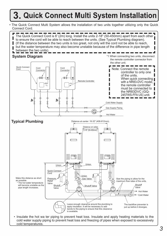
3. Quick Connect Multi System Installation• The Quick Connect Multi System allows the installation of two units together utilizing only the Quick
Connect Cord.
The Quick Connect Cord is 6' (2m) long. Install the units 2-18" (50-450mm) apart from each other to ensure the cord will be able to reach between the units. (See Typical Plumbing diagram). (If the distance between the two units is too great, not only will the cord not be able to reach,but the water temperature may also become unstable because of the difference in pipe length between the two units).
*1 When connecting two units, disconnect the remote controller connector from the other unit.
Note: Connect the remote controller to only one of the units.
When quick connecting with a NR83-DVC model,
the remote controller must be connected to the NR83DVC (GQ-2457WS-FFA US) unit.
System Diagram
• Insulate the hot wa ter piping to prevent heat loss. Insulate and apply heating materials to the cold water supply piping to prevent heat loss and freezing of pipes when exposed to excessively cold temperatures.
Size the piping to allow for themaximum flow rates of the units.
Distance at center: 16-32" (406-812mm).
Union
Hot Water
Shutoff Valve
Cold Water
Distance on sides2-18" (50-450mm).
Union
Quick ConnectCord
PressureReliefValve
ShutoffValve
UnionGas Valve
Shutoff Valve
Leave enough clearance around the plumbing to apply insulation. It will be necessary to add bends to the piping to ensure that this clearance is available.
Make this distance as short as possible. * The hot water temperature will become unstable as the pipe length increases.
The backflow preventer isput up before it diverges.
Typical Plumbing
�
180,000
151,200
2.2
2.5" 2.5"
2.2
172,000
144,500
180,000 BTU18,000 BTU
1824.01.0 2.5"
10.5"689
ANSI Z21.10.3-2014/CSA 4.3-2014
15 1502
NR83DVC (GQ-2457WS-FFA US)
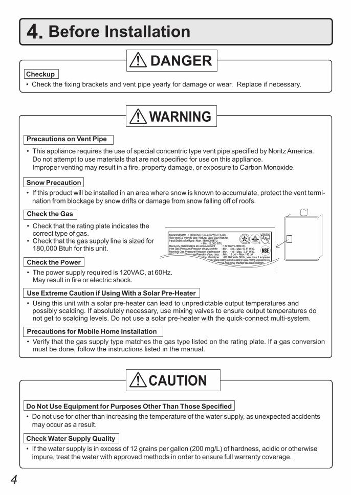
4. Before Installation
Checkup• Check the fixing brackets and vent pipe yearly for damage or wear. Replace if necessary.
DANGER
Do Not Use Equipment for Purposes Other Than Those Specified• Do not use for other than increasing the temperature of the water supply, as unexpected accidents
may occur as a result.
Check Water Supply Quality• If the water supply is in excess of 12 grains per gallon (200 mg/L) of hardness, acidic or otherwise
impure, treat the water with approved methods in order to ensure full warranty coverage.
WARNING
CAUTION
Check the Gas
• Check that the rating plate indicates the correct type of gas.• Check that the gas supply line is sized for 180,000 Btuh for this unit.
Check the Power• The power supply required is 120VAC, at 60Hz. May result in fire or electric shock.
Use Extreme Caution if Using With a Solar Pre-Heater• Using this unit with a solar pre-heater can lead to unpredictable output temperatures and possibly scalding. If absolutely necessary, use mixing valves to ensure output temperatures do
not get to scalding levels. Do not use a solar pre-heater with the quick-connect multi-system.
Precautions for Mobile Home Installation• Verify that the gas supply type matches the gas type listed on the rating plate. If a gas conversion
must be done, follow the instructions listed in the manual.
Precautions on Vent Pipe
• This appliance requires the use of special concentric type vent pipe specified by Noritz America. Do not attempt to use materials that are not specified for use on this appliance.
Improper venting may result in a fire, property damage, or exposure to Carbon Monoxide.
Snow Precaution• If this product will be installed in an area where snow is known to accumulate, protect the vent termi-
nation from blockage by snow drifts or damage from snow falling off of roofs.

�
5. Choosing Installation Site* Locate the appliance in an area where leakage from the unit or connections will not result in damage
to the area adjacent to the appliance or to the lower floors of the structure. When such installation locations cannot be avoided, a suitable drain pan, adequately drained, must be installed under the appliance. The pan must not restrict combustion air flow.
* As with any water heating appliance, the potential for leakage at some time in the life of the product does exist. The manufacturer will not be responsible for any water damage that may occur.
• Locate the vent terminal so that there are no obstacles around the termination and so that exhaust can't accumulate. Do not enclose the termination with corrugated metal or other materials.
• Avoid places where fires are common, such as those where gasoline, benzene and adhesives are handled, or places in which corrosive gases (ammonia, chlorine, sulfur, ethylene compounds, acids) are present.
Using the incorrect voltage may result in fire or cracking.
• Avoid installation in places where dust or debris will accumulate.Dust may accumulate and reduce the performance of the unit's fan. This can result in incomplete combustion.
• Avoid installation in places where special chemical agents (e.g., hair spray or spray detergent) are used.
Ignition failures and malfunction may occur as a result.
• Carbon Monoxide Poisoning Hazard. Do not install this water heater in a recreational vehicle or on a boat.
• The manufacturer does not recommend installing the water heater in an attic due to safety issues.
If you install the water heater in an attic:• Make sure the unit will have enough combustion air and proper ventilation.• Keep the area around the water heater clean. Dust may accumulate and
reduce the performance of the unit's fan. This can result in incomplete combustion.
• Place the unit for easy access for service and maintenance.• A drain pan, or other means of protection against water damage, is
required to be installed under the water heater in case of leaks.
Prohibited
DANGER
WARNING

�
• Avoid installation above gas ranges or stoves.
• Avoid installation between the kitchen fan and stove. If oily fumes or a large amount of steam are present in the installation location, take measures to prevent the fumes and steam from entering in the equipment.
• Install in a location where the exhaust gas flow will not be af-fected by fans or range hoods.
• Take care that noise and exhaust gas will not affect neighbors. Avoid installation on common walls as the unit will make some operational noises while it is running.
• Before installing, make sure that the exhaust flue termination will have the proper clearances according to the National Fuel Gas Code (ANSI Z223.1-latest edition) or the Natural Gas and Propane Installation Code (CSA B149.1).
State of California: The water heater must be braced, anchored or strapped to avoid moving during an earthquake. Contact local utilities for code requirements in your area or call: 1-866-766-7489 and re-quest instructions.
Be sure to do
Prohibited
Prohibited
CAUTION
The Commonwealth of Massachusetts: The water heater can be used for hot water only and not in a combination of domestic and space heating.
For Venting Manufacturers Requirements, see websites or phone numbers listed below:
Noritz N-Vent www.noritz.com
• The water heater is designed for indoor installation only. Never install it outdoors or in a bathroom, it may be damaged or a fire may be caused.
• Consult with the customer concerning the location of installation.• Install the water heater in an area that allows for the proper clearances
to combustible and noncombustible construction. Consult the rating plate on the appliance for proper clearances.
• Do not install the water heater in a place where it may be threatened by falling objects, such as under shelves.
• The water heater must be installed in a place where supply and exhaust pipes can be installed as directed.
• Do not install the water heater where the exhaust will blow on outer walls or material not resistant to heat. Also consider the surrounding trees and animals.
The heat and moisture from the water heater may cause discoloration of walls and resinous materials, or corrosion of aluminum materials.
Prohibited

�
6. Installation Clearances
Before installing, check for the following:Install in accordance with relevant building and mechanical codes, as well as any local, state or national regulations, or in the absence of local and state codes, to the National Fuel Gas Code ANSI Z223.1/NFPA 54 – latest edition. In Canada, see the Natural Gas and Propane Installation Code CSA B149.1 - latest edition for detailed requirements.
WARNING
Item
Dis
tanc
e fro
m c
ombu
stib
les
• Maintain the following clearances from both combustible and non-combustible materials.
Check Illustration
• If possible, leave 8" (200mm) or more on either side of the unit to facilitate inspection.
• If possible, leave 24" (600mm) or more in front of the unit to facilitate maintenance and service if necessary.
• If possible, leave 3" (75mm) or more above and below the vent pipe to facilitate inspection and repair if necessary.
Sec
urin
g of
spa
ce fo
r re
pair/
insp
ectio
n
24" (600mm) or more
8" (200mm) or more
Distance from the side
12" (300mm) or more
2" (50mm) or more
3" (75mm) or more
3" (75mm) or more
4" (100mm) or more
8" (200mm) or more

�
7. Installation Securing to the wall
Clearance Requirements from Vent Terminations to Building Openings* All clearance requirements are in accordance with ANSI Z21.10.3 and the National Fuel Gas Code,
ANSI Z223.1 and in Canada, in accordance with the Natural Gas and Propane Installation Code CSA B149.1.
DescriptionRef
A= Clearance above grade, veranda, porch, deck, or balcony
B=Clearance to window or door that may be opened
C= Clearance to permanently closed window
D=
Vertical clearance to ventilated soffit located above the terminal within a horizontal distance of 2 feet (61 cm) from the center line of the terminal
*
E= Clearance to unventilated soffit *F= Clearance to outside corner *G= Clearance to inside corner *
H= Clearance to each side of center line extended above meter/regulator assembly
3 ft (91 cm) within a height15 ft (4.6 m) above themeter/regulator assembly
I= Clearance to service regulator vent outlet 3 ft (91 cm)
J=Clearance to nonmechanical air supply inlet to building or the combustion air inlet to any other appliance
K= Clearance to a mechanical air supply inlet 6 ft (1.83 m)
L= Clearance above paved sidewalk or paved driveway located on public propertyClearance under veranda, porch, deck, or balcony
7 ft (2.13 m)†
M=
1 In accordance with the current CSA B149.1 Natural Gas and Propane Installation Code2 In accordance with the current ANSI Z223.1 / NFPA 54 National Fuel Gas Code† A vent shall not terminate directly above a sidewalk or paved driveway that is located between two single family dwellings and serves both dwellings.‡ Permitted only if veranda, porch, deck, or balcony is fully open on a minimum of two sides beneath the floor.* Clearance in accordance with local installation codes and the requirements of the gas supplier. Clearance to opposite wall is 24 inches (60 cm).
12 in (30 cm)‡
*
12 in (30 cm)
36 in (91 cm)
*
***
*
*
*
*
3 ft (91 cm) above if within10 ft (3 m) horizontally
*
12 in (30 cm)
12 in (30 cm)
12 in (30 cm)36 in (91 cm)
US Direct VentInstallations 2
Canadian Direct VentInstallations 1
Vent Terminal
D
E
B
B
F
B
A
G
H
IC B
M
KJ
B
B
L
Air Supply InletArea Where Terminalis Not Permitted
A

�
IllustrationCheck
6. Drill holes for the remaining four screws.
7. Hang the unit again by the first screw, and then insert and tighten the remaining four screws.
8. Take waterproofing measures so that water does not enter the building from screws mounting the device.
• Make sure the unit is installed securely so that it will not fall or move due to vibrations or earthquakes.
• The distance between the unit and the wall can be adjusted within the range of 0.4 - 1.8" (10 - 46mm). Adjust the brackets as necessary to accommodate the vent system (factory default is 0.4" (10mm)).
1. Loosen the four screws in the mounting bracket (upper), match the desired mark to the back of the unit, and then tighten the screws.
2. Loosen the four screws in the mounting bracket (lower) and secure it in the same position as the upper mounting bracket.
3. Drill a single screw hole, making sure to hit a stud.4. Insert and tighten the screw and hang the unit by
the upper wall mounting bracket.5. Determine the positions for the remaining four screws
(two for the top bracket and two for the bottom), and remove the unit.
• The weight of the device will be applied to the wall. If the strength of the wall is not suffi-cient, reinforcement must be done to prevent the transfer of vibration.
• Do not drop or apply unnecessary force to the device when installing. Internal parts may be damaged and may become highly dangerous.
• Install the unit on a vertical wall and ensure that it is level.
Loca
ting
Scr
ew H
oles
Mou
ntin
gSt
ructu
re
• When installing with bare hands, take caution to not inflict injury.
• Be careful not to hit electrical wiring, gas, or water piping while drilling holes.
Item
CAUTION
Be sure to do
Mounting Bracket(upper)
Anchoring Screw
Location of Screw Hole
Locating Screw Holes
Inst
alla
tions
at E
leva
tions
Ab
ove
2,00
0 ft.
(610
m).
• Adjust the dip switches as illustrated in the table to the right if this water heater is installed at an altitude of 2000 ft. (610m) or higher.
• Disconnect power to the water heater before chang-ing the dip switches. Failure to perform this step will result in a "73" code displayed on the remote control-ler and a cease in operation. If this occurs, discon-nect, then reconnect power to the water heater to reset the system.
Note : Please refer to page 27 for the location of the dip switch bank.
0.4 - 1.8"(10 - 46mm)
mounting bracket (upper)
mounting bracket (lower)
mark (0.4" (10mm) intervals)
* Do not change any other dipswitches.
* High elevation adjustment.
65
2,001 - 4,000 ft (611 - 1,220m)
0 - 2,000 ft (0 - 610m)
ON= OFF=
4,001 - 6,000 ft (1,221 - 1,830m)
6,001 - 8,000 ft (1,831 - 2,440m)

10
> 3" (75mm)(20-75mm)0.8"-3" < 0.8"
(20mm)
Straight Termination Installation Precautions. Note the following vent terminal installation requirements.• Do not install the vent terminal indoors
• Install the vent terminal with a downward slope
upwardslope
downwardslope
• Install with the proper length protruding through the wall • Avoid storing hazardous objects near the terminal
Gasoline
Gas
Proper installation. The red line can be seen, but not more than 2.2" (55mm) from the wall.
Vent terminalVent terminal
not farenough
too far
Snow drift Tree
• Avoid installing the terminal where obstacles will block it
• Do not cover the vent terminal with any type of protective screen or enclosure. Blocked terminals can cause abnor-mal combustion resulting in undesired performance from the water heater.
8. Vent Pipe Installation
• This appliance requires the use of special concentric type vent pipe specified by Noritz America. Do not attempt to use materials that are not specified for use on this appliance.
WARNING
Be sure to do
CARBON MONOXIDE POISONINGFollow all vent system requirements in accordance with relevant local or state regulation, or, in the absence of local or state code, in the U.S. to the National Fuel Gas Code ANSI Z233.1/NFPA 54 – latest edition, and in Canada, in accordance with the Natural Gas and Propane Installation Code CSA B149.1 – latest edition.
• Clearance from vent terminal. If multiple units are installed, the concentric vent terminals must be separated
by a minimum of either 12" (300mm) horizontally or 60" (1.5m) vertically.
Vent terminal Vent terminal
12" (300mm) or more
60" (1.5m) or more

11
The power must be unplugged when adjusting the dip switches to switch the airflow amount.
The unit can be adjusted to accommodate longer vent runs; refer to the below table to find the maximum vent length based on the number of elbows. Adjust the dip switches according to the vent condition noted in the tables below.Note: By default, the unit has been set to the " 1 minimum length" condition. When adjusting the dip
switches for longer vent runs, the BTUH input of the appliance will be reduced by up to 7%.
Maximum Vent Length Adjustment Dipswitches
- Two 90 elbows, maximum length = 3 ft (0.9m) (with dip switches set at "minimum length" condition)
- Two 90 elbows, maximum length = 29 ft (9m) (with dip switches set at "maximum length" condition)
[Maximum Vent Length Example]
• Disconnect power to the water heater before changing the dip switches. Failure to perform this step will result in a "73" code displayed on the remote controller and a cease in operation. If this occurs, disconnect, then reconnect power to the water heater to reset the system.
Note : Please refer to page 27 for the location of the dip switch bank.
369
12151821242730323538
0.901.802.703.604.505.406.307.208.109.009.90
10.8011.70
m 10 2 3 4 5 6ftVent length* Elbows
123456789
10111213
Number ofpieces**
12
34
Minimum lengthShort length***
Long length**** Maximum length****
**Table assumes straight vent pieces are 3’ (0.9m) each. Shorter or longer vent pieces may also be used up to the maximum allowed vent length.
*** The BTUH input of the appliance will be reduced by up to 3%.****The BTUH input of the appliance will be reduced by up to 6%.
<Maximum Vent Length Configurations>
* Do not change any other dipswitches.
* Vent length condition.
1 Minimum length
7 8
ON= OFF=
2 Short length
3 Long length
4 Maximum length

12
Drain condensate according to local codes.
HangerStraps
Elbow
Slope ventterminationdownwards
Plate
Termination (CVT-S)
Wall Flange-Female Model
(CWF-F)
Slope ventdownwards
Condensate collector must be used if the total vent run exceeds 3' (0.9m).
Horizontal Vent Termination • Terminate at least 12" (300mm) above grade or above snow line.
• Terminate at least 7' (2.1m) above a public walkway, 6' (1.8m) from the combustion air intake of any appliance, and 3' (0.9m) from any other building opening, gas utility me-ter, service regulator etc.
• Terminate at least 3' (0.9m) above any forced air inlet within 10' (3m), 1' (0.3m) below, 1' (0.3m) horizontally from or 1' (0.3m) above any door, window, or gravity air inlet into any building per National Fuel Gas Code ANSI Z223.1/NFPA 54 or the Natural Gas and Propane Installation Code CSA B149.1.
• Slope the horizontal vent 1/4" (6mm) downwards for every 12" (300mm) towards the unit.
• Slope the vent termination piece downwards towards the terminating wall.
• The integrated condensate collector must be used for total vent runs in excess of 3' (0.9m). Remove the cap from the collector prior to at-taching the drain line.
• In the Commonwealth of Massachusetts a car-bon monoxide detector is required for all side wall horizontally vented gas fuel equipment. Please refer to Technical Bulletin TB 010606 for full installation instructions.
• Connect the vent pipe firmly so that it will pre-vent exhaust gases from leaking.
• Steam or condensed water may drip out of the vent terminal. Dispose of this condensed water according to local codes and in order to prevent injury or property damage.
• If this product will be installed in an area where snow is known to accumulate,protect the vent termination from blockage by snow drifts or damage from snow falling off of roofs.
• Support the vent pipe with hangers at a mini-mum of every 7' (2.1m).
• Make the vertical pipe as short as possible.• Do not common vent or connect more than
one appliance to this venting system.• Terminate at least 12" (300mm) above grade or
snow line.• Terminate at least 7' (2.1m) above a public
walkway.
• Exceeding the maximum vent length is danger-ous and may result in bad combustion.
• Install the vent terminal so that all exhaust is di-rected to and all intake air is taken from outdoors.
• Do not store hazardous or flammable substanc-es near the vent terminal.
• Slope the vent pipe 1/4" (6mm) for every 12" (300mm) either towards the horizontal termination or towards the integrated condensate collector.
When using the condensate collector, create a trap in the drain line and pre-charge it with wa-ter to prevent exhaust gas leakage.
• Maintain the same vent pipe diameter all the way to the end.
• Noritz Concentric vent pipe is approved for use on this appliance with zero clearance to com-bustibles.
• Use only Noritz specified venting products.
WARNING
Be sure to do
CARBON MONOXIDE POISONINGDo not remove the cap from the condensate collector unless it is being used to drain condensate. Without the cap in place, flue products could enter the living space.

13
(Combustible material)
External wall, combustible material.
• Inspection openings are suggested for the vent intake and exhaust pipes if they are installed in an enclosure. These openings should be near the entrance and exit of the vent into the enclosure.
• These openings should be 18" x 18" (450mm x 450mm).
Suggested inspection openings18" x 18" (450mm x 450mm)
When the vent pipe passes through an enclosed space:
Ceiling
Sloping down toward the unit.
Vertical Vent Termination
Drain condensate according to local codes.
HangerStraps
Elbow
Slope ventUpwards
Firestop
Condensate collector must beused if the total vent runexceeds 3' (0.9m).
Elbow
Firestop/Support
Roof Flashing(Base and Adapter)
Rain Cap
Air IntakePipe
5' (1.5m) or more
WARNINGProhibited to install 90 degree adjustableelbow (CVP-90ADJELB) in this portion.Install 90 degree elbow (CVP-90ELB) only.
• Terminate at least 6' (1.8m) from the combus-tion air intake of any appliance, and 3' (0.9m) from any other building opening, gas utility me-ter, service regulator etc.
• Enclose exterior vent systems below the roof line to limit condensation and protect against mechanical failure.
• When the vent penetrates a floor or ceiling and is not running in a fire rated shaft, a firestop and support is required.
• When the vent termination is located not less than 8' (2.4m) from a vertical wall or similar obstruc-tion, terminate above the roof at least 2' (0.6m), but not more than 6' (1.8m), in accordance with the National Fuel Gas Code ANSI Z223.1/NFPA 54 or Natural Gas and Propane Installa-tion Code CSA B149.1.
• Provide vertical support every 7' (2.1m).• Slope the horizontal vent 1/4" for every
12" (300mm) towards the drain tee.• The integrated condensate collector must be
used for total vent runs in excess of 3' (0.9m). Remove the cap prior to attaching the drain tubing.
• When 2 units are installed in a Quick Connect Multi System, maintain a minimum distance of 5' (1.5m) between the vertical terminations.
14
Follow the instructions from the gas supplier.9. Gas Piping
Gas TypeThe gas type indicated on the water heater rating plate (NG or LP) must match the type of gas being supplied to the water heater.
Gas ConversionsIf the gas type supplied does not match the gas type on the rating plate, obtain a replacement unit with the proper gas type. If a gas type conversion must be made, there are conversion kits available for some models. [The conversion kit shall be installed by a qualified service agency in accordance with the manufacturer’s instructions and all applicable codes and requirements of the authority having jurisdiction. The qualified service agency is responsible for the proper installation of this kit. Improper installation of this kit will void the warranty.]
MeterThe gas meter must be sized properly for the water heater and other gas appliances to operate properly. Select a gas meter capable of supplying the entire btuh demand of all gas appliances in the building.
The guidelines and examples we have provided in this manual section are for reference only.The sizing and installation of the gas system for this water heater, as with any gas appliance, is the sole responsibility of the installer. The installer must be professionally trained to do such work and must always follow all local and national codes and regulations. Gas line sizing calculations must be performed for every installation. Please contact Noritz America at 866-766-7489 if you have any questions or concerns.
CAUTION
RegulatorsEnsure that all gas regulators used are operating properly and providing gas pressures within the specified range of the water heater being installed. Excess gas inlet pressure may cause serious accidents.
CAUTION
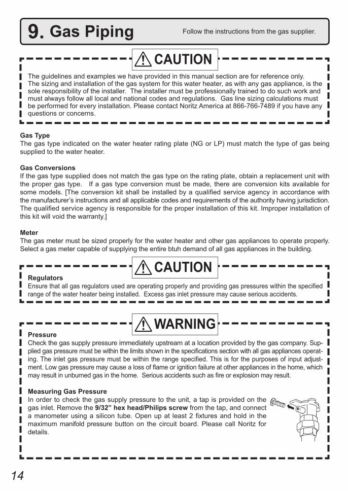
PressureCheck the gas supply pressure immediately upstream at a location provided by the gas company. Sup-plied gas pressure must be within the limits shown in the specifications section with all gas appliances operat-ing. The inlet gas pressure must be within the range specified. This is for the purposes of input adjust-ment. Low gas pressure may cause a loss of flame or ignition failure at other appliances in the home, which may result in unburned gas in the home. Serious accidents such as fire or explosion may result.
Measuring Gas PressureIn order to check the gas supply pressure to the unit, a tap is provided on the gas inlet. Remove the 9/32” hex head/Philips screw from the tap, and connect a manometer using a silicon tube. Open up at least 2 fixtures and hold in the maximum manifold pressure button on the circuit board. Please call Noritz for details.
WARNING

15
Pressure TestThe appliance and its gas connections must be leak tested before placing the appliance in operation. The appliance must be isolated from the gas supply piping system by closing its individual manual shutoff valve during any pressure testing of the gas supply piping system at test pressures equal to or less than ½ psig (3.5 kPa). We do not recommend pressure testing in excess of ½ psig (3.5kPa). If it must be done, the appliance and its individual shutoff valve must be completely disconnected from the gas supply piping system during the test process.
Pipe Sizing/Flexible Connectors A gas shutoff valve must be installed on the supply line. Gas flex lines are not recommended unless the minimum inside diameter is ¾” or greater and the rated capacity of the connector is equal to or greater than the BTU capacity of the water heater. Gas piping shall be in accordance with local utility company requirements and/or in the absence of local codes, use the latest edition of National Fuel Gas Code (NFPA54GC), ANSI Z223.1. Size the gas line according to total btuh demand of the building and length from the meter or regulator so that the following supply pressures are available even at maximum demand.
WARNING
Natural Gas Supply PressureMin 4” WCMax 10.5” WC
LP Gas Supply PressureMin 8” WCMax 14” WC
Reference Tools & Sample Calculations
The tables and samples below are for reference only. The professional sizing and installing the gas line should always run the appropriate calculations before all installations.
CAUTION
Which Table to Use• For NG installations with the initial supply pressure at point of delivery (at the meter, for example) is
less than 8” WC, use the 0.5” WC pressure drop table (Table 1). • For NG installations with the initial supply pressure at point of delivery is greater than or equal to 8”
WC, use the 3.0” pressure drop table (Table 2). • For all LP installation use (Table 3)
The inlet pressure must be at least 5” WC for NG or 8” WC for LP for all appliances in the gas system.If the inlet gas pressure drops below 5” WC for NG or 8” WC for LP, the heater may continue to operate, but the other appliances in the house may experience flame loss or ignition failure, which can result in gas leakage into the home. Refer to the NFPA 54 for details.
Please contact Noritz for details. For corrugated stainless steel tubing (CSST) capacity tables, please consult with the manufacturer.

16
Pipe Size
Length (including fittings)10' 20' 30' 40' 50' 60' 70' 80' 90' 100' 125'
(3m) (6m) (9m) (12m) (15m) (18m) (21m) (24m) (27m) (30m) (38m)3/4" 360 247 199 170 151 137 126 117 110 104 921" 678 466 374 320 284 257 237 220 207 195 173
1 1/4" 1,390 957 768 657 583 528 486 452 424 400 3551 1/2" 2,090 1,430 1,150 985 873 791 728 677 635 600 532
2" 4,020 2,760 2,220 1,900 1,680 1,520 1,400 1,300 1,220 1,160 1,0202 1/2" 6,400 4,400 4,400 3,020 2,680 2,430 2,230 2,080 1,950 1,840 1,630
3" 11,300 7,780 7,780 5,350 4,740 4,290 3,950 3,760 3,450 3,260 2,8904" 23,100 15,900 12,700 10,900 9,660 8,760 8,050 7,490 7,030 6,640 5,890
Table 1. For Less than 8” WC initial supply pressure Maximum Natural Gas Delivery Capacity (0.5” Pressure Drop) [Schedule 40 Metalic Pipe]
Values in Table are in Cubic Feet of Gas per Hour (0.60 Specific Gravity, 0.5” Pressure Drop, inlet pressure less than 2psi). Contact your gas supplier for BTU/Cubic Foot ratings. For simplification of your calculations, 1 Cubic Foot of Gas is approximately equivalent to 1000 BTU.
Table 2. For 8” WC – 10.5” WC initial supply pressure Maximum Natural Gas Delivery Capacity (3.0” Pressure Drop) [Schedule 40 Metalic Pipe]
Values in Table are in Cubic Feet of Gas per Hour (0.60 Specific Gravity, 3.0” Pressure Drop, 8.0” WC or greater supply pressure, inlet pressure less than 2psi). Contact your gas supplier for BTU/Cubic Foot ratings. For simplification of your calculations, 1 Cubic Foot of Gas is approximately equivalent to 1000 BTU.
Instructions1. Size each outlet branch starting from the furthest using the Btuh required and the length from the meter.2. Size each section of the main line using the length to the furthest outlet and the Btuh required by everything after that section.
Sample Gas Line
Sample Calculation - (Using 0.5” WC Pressure Drop Table)Outlet A: 45' (13.5m) (Use 50' (15m)), 50,000 Btuh requires 1/2"Outlet B: 40' (12m), 65,000 Btuh requires 1/2"Section 1: 45' (13.5m) (Use 50' (15m)), 115,000 Btuh requires 3/4"Outlet C: 30' (9m), 35,000 Btuh requires 1/2"Section 2: 45' (13.5m) (Use 50' (15m)), 150,000 Btuh requires 3/4"Outlet D: 25' (7.5m) (Use 30' (9m)), 25,000 Btuh requires 1/2"Section 3: 45' (13.5m) (Use 50' (15m)), 175,000 Btuh requires 1"Outlet E: 25' (7.5m) (Use 30' (9m)), 180,000 Btuh requires 3/4" Section 4: 45' (13.5m) (Use 50' (15m)), 355,000 Btuh requires 1 1/4"Natural Gas
Meter
Noritz Tankless Gas Water Heater(180,000 Btuh)
Clothes Dryer(35,000 Btuh)
Barbecue(50,000 Btuh)
Gas Range Stove(65,000 Btuh)
10' (3m)10' (3m)
10' (3m)
10' (3m)
5' (1.5m)
5' (1.5m)5' (1.5m)
5' (1.5m)5' (1.5m) 5' (1.5m)
Gas Fireplace(25,000 Btuh)
Section 3 Section 2 Section 1
Outlet A
Outlet B
Outlet C
Outlet D
Outlet E
Section 4
Natural GasMeter
Clothes Dryer(35,000 Btuh)
Barbecue(50,000 Btuh)
Gas Range Stove(65,000 Btuh)
10' (3m)10' (3m)
10' (3m)
10' (3m)
5' (1.5m)
5' (1.5m)5' (1.5m)
5' (1.5m)5' (1.5m) 5' (1.5m)
Gas Fireplace(25,000 Btuh)
Instructions1. Size each outlet branch starting from the furthest using the Btuh required and the length from the meter.2. Size each section of the main line using the length to the furthest outlet and the Btuh required by everything after that section.
Sample Gas Line
Sample Calculation (Using 3.0” WC Pressure Drop Table)Outlet A: 45' (13.5m) (Use 50' (15m)), 50,000 Btuh requires 1/2"Outlet B: 40' (12m), 65,000 Btuh requires 1/2"Section 1: 45' (13.5m) (Use 50' (15m)), 115,000 Btuh requires 1/2"Outlet C: 30' (9m), 35,000 Btuh requires 1/2"Section 2: 45' (13.5m) (Use 50' (15m)), 150,000 Btuh requires 1/2"Outlet D: 25' (7.5m) (Use 30' (9m)), 25,000 Btuh requires 1/2"Section 3: 45' (13.5m) (Use 50' (15m)), 175,000 Btuh requires 1/2"Outlet E: 25' (7.5m) (Use 30' (9m)), 180,000 Btuh requires 1/2"Section 4: 45' (13.5m) (Use 50' (15m)), 355,000 Btuh requires 3/4"
Section 3 Section 2 Section 1
Outlet A
Outlet B
Outlet C
Outlet D
Outlet E
Section 4
Noritz Tankless Gas Water Heater(180,000 Btuh)
Pipe Size
Length (including fittings)10' 20' 30' 40' 50' 60' 70' 80' 90' 100' 125'
(3m) (6m) (9m) (12m) (15m) (18m) (21m) (24m) (27m) (30m) (38m)1/2" 454 312 250 214 190 172 158 147 138 131 1163/4" 949 652 524 448 397 360 331 308 289 273 2421" 1,787 1,228 986 844 748 678 624 580 544 514 456
1 1/4" 3,669 2,522 2,025 1,733 1,536 1,392 1,280 1,191 1,118 1,056 9361 1/2" 5,497 3,778 3,034 2,597 2,302 2,085 1,919 1,785 1,675 1,582 1,402
2" 10,588 7,277 5,844 5,001 4,433 4,016 3,695 3,437 3,225 3,046 2,7002 1/2" 16,875 11,598 9,314 7,971 7,065 6,401 5,889 5,479 1,540 4,856 4,303
3" 29,832 20,503 16,465 14,092 12,489 11,316 10,411 9,865 9,087 8,584 7,6084" 43678 30,020 24,107 20,632 18,286 16,569 15,243 14,181 13,305 12,568 11,139

17
Table 3. Maximum Undiluted Propane (LP) Delivery Capacity in Thousands of BtuH (0.5” WC Pressure Drop) [Schedule 40 Metalic Pipe]
For reference only. Please consult gas pipe manufacturer for actual pipe capacities.
Final CheckWhen the installation is complete, verify that inlet gas pressure for the entire gas system does not drop below 5” WC for NG or 8” WC for LP at all appliances. This can be tested by turning on all gas burning appliances including the water heater, then check the inlet pressure at each appliance to verify all appliances are receiving a minimum of 5” WC for NG or 8” WC for LP. If all appliances are not receiving the minimum inlet pressure the gas piping system may need to be changed.
CAUTION
Pipe Size
Length (including fittings)10' 20' 30' 40' 50' 60' 70' 80' 90' 100' 125' 150' 200'
(3m) (6m) (9m) (12m) (15m) (18m) (21m) (24m) (27m) (30m) (38m) (45m) (60m)1/2" 275 189 152 129 114 103 96 89 83 78 69 63 553/4" 567 393 315 267 237 217 196 185 173 162 146 132 1121" 1,071 732 590 504 448 409 378 346 322 307 275 252 213
1 1/4" 2,205 1,496 1,212 1039 913 834 771 724 677 630 567 511 4401 1/2" 3,307 2,299 1,858 1,559 1,417 1,275 1,181 1,086 1,023 976 866 787 675
2" 6,221 4,331 3,465 2,992 2,646 2,394 2,205 2,047 1,921 1,811 1,606 1,496 1,260

18
10. Water PipingThis appliance is suitable for potable water and space heating applications. Do not use this appliance if any part has been underwater. Immediately call a qualified service technician to inspect the appliance and replace any part of the control system and gas control which has been under water.
If the water heater is installed in a closed water supply system, such as one having a backflow preventer in the cold water supply line, means shall be provided to control thermal expansion. Contact the water supplier or a local plumbing inspector on how to control this situation.
A pressure relief valve must be installed near the hot water outlet that is rated in accordance with and complying with either The Standard for Relief Valves and Automatic Shutoff Devices for Hot Water Supply Systems, ANSI Z21.22, or The ANSI/ASME Boiler and Pressure Vessel Code, Section IV ( Heating Boilers ). This pressure relief valve must be capable of an hourly Btu rated temperature steam discharge of 180,000 Btuh. Multiple valves may be used. The pressure relief capacity must not exceed 150 psig. No valve shall be placed between the relief valve and the water heater. The relief valve must be installed such that the discharge will be conducted to a suitable place for disposal when relief occurs. No reducing coupling or other restriction may be installed in the discharge line. The discharge line must be installed to allow complete drainage of both the valve and the line. If this unit is installed with a separate storage vessel, the separate vessel must have its own temperature and pressure relief valve. This valve must also comply with The Standard for Relief Valves and Automatic Gas Shutoff Devices for Hot Water Supply Systems, ANSI Z21.22. (in the U.S. only). A temperature relief valve is not required, but if one is used, do not install the valve with the probe directly in the flow of water. This may cause unwarranted discharge of the valve.
Piping and components connected to the water heater shall be suitable for use with potable water.Toxic chemicals, such as those used for boiler treatment, shall not be introduced into the potable water.A water heater used to supply potable water may not be connected to any heating system or components previ-ously used with a nonpotable water heating appliance.When water is required in one part of the system at a higher temperature than in the rest of the system, means such as a mixing valve shall be installed to temper the water to reduce the scald hazard.
Installation and service must be performed by a qualified plumber. In the Commonwealth of Massachusetts, this product must be installed by a licensed plumber or gas fitter in accordance with the Massachusetts Plumbing and Fuel Gas Code 248 CMR Sections 2.00 and 5.00. Observe all applicable codes.
• Flush water through the pipe to clean out metal powder, sand and dirt before connecting it.• Perform the following insulation measures for prevention of freezing.
• Take appropriate heat insulation measures (e.g., wrapping with heat insulation materials, using electric heaters) according to the climate of the region to prevent the pipe from freezing.
• Make sure that there are no water leaks from the cold and hot water supply pipes, then insulate the pipes completely.
• Be sure to also completely insulate the water supply valve and the cold and hot water connections on the water heater (refer to the fig-ure on the right).
• Do not cover the water drain plug with insulation so that water in the pipe can be drained. (Refer to the figure in the right.)
• Use a union coupling or flexible pipe for connecting the pipes to reduce the force applied to the piping.• Do not use piping with a diameter smaller than the coupling.• When feed water pressure is too high, insert a depressurizing valve, or take water hammer prevention measure.• Avoid using joints as much as possible to keep the piping simple.• Avoid piping in which an air holdup can occur.• If installing the unit on a roof:• About lower-level hot water supply If the unit is installed on a roof to supply water to the levels below, make sure that the water pressure supplied
to the unit does not drop below 29 psi. It may be necessary to install a pump system to ensure that the water pressure is maintained at this level.
Check the pressure before putting the unit into operation. Failure to supply the proper pressure to the unit may result in noisy operation, shorter lifetime of the unit, and
may cause the unit to shut down frequently.
Completely insulate the water inlet and outlet fittings.
Insulate the water supply valve completely.
Do not cover the water drain plug with insulation so that water in the pipe can be drained.

19
Supply water piping• Do not use PVC, iron, or any piping which has been
treated with chromates, boiler seal or other chemicals.• Mount a check valve and a shut off valve (near the inlet).• In order for the client to use the water heater
comfortably, 98.1 to 491 kPa (14 to 70 PSI) of pressure is needed from the water supply.
Be sure to check the water pressure. If the water pressure is low, the water heater cannot perform to its full capability, and may become a source of trouble for the client.
Drain piping• Expansion water may drop from the pressure
relief valve and wet the floor. If necessary, provide drain piping or use a drain
hose to remove the water.
Hot water piping• Do not use lead, PVC, iron or any piping which
has been treated with chromates, boiler seal or other chemicals.
• The longer the piping, the greater the heat loss. Try to make the piping as short as possible.
• Use mixing valves with low water resistance. Use shower heads with low pressure loss.
• If necessary, use a pump or other means to en-sure that the supply water pressure to the inlet of the heater does not fall below 29 PSI when the maximum amount of water is being demand-ed. Also install a pressure meter on the inlet. If this is not done, local boiling will occur inside the water heater causing abnormal sounds and decreasing the durability of the heat exchanger.
Freeze Prevention• Freezing is prevented within the device automatically unless the outside temperature without wind
is below -30°F (-35°C).• If this model is installed in an area where the outside temperature can approach freezing conditions
of -30°F (-35°C) or below, then additional freeze protection measures must be used. For temporary freeze protection measures, refer to the Owner's Guide.
• The freeze prevention heaters will not prevent the plumbing external to the unit from freezing. Protect this plumbing with insulation, heat tape or electric heaters, solenoids, or pipe covers.
• In order for the freeze prevention heaters to operate, the water heater must have power at all times.
Total Hardness* : 200 mg/L (12 gpg) or lessAluminum : 0.05 to 0.2 mg/L or lessChloride : 250 mg/L or lessCopper : 1 mg/L or lessIron : 0.3 mg/L or lessManganese : 0.05 mg/L or lesspH : 6.5 - 8.5Total Dissolved Solids : 500 mg/L or lessZinc : 5 mg/L or lessSulfate ion : 250 mg/L or less Residual chlorine : 4 mg/L or less* Maximum limit suggested by Noritz.
Damage to the water heater as a result of the below is not covered by the Noritz America Limited Warranty.• Water in excess of 12 gpg (200mg/L) of
hardness • Poor water quality (see table to the right)

20
Water Treatment
Water Treatment System
City Water Supply
PressureReliefValve
Hot Water to Fixtures
Shutoff Valve
Drain
Cold to WaterHeater
Optional Sediment Filter
Water Treatment Device
Shutoff Valve
Type of Water Hardness Level Treatment Device* Flush Frequency**
Soft 0-1 gpg
1-3 gpg
(0-17 mg/L) None None
Slightly Hard (17-51 mg/L) None None
Moderately Hard
Hard
3-7 gpg (51-120 mg/L)
H2Flow or ScaleShieldH2Flow or ScaleShield
Once a Year*** orFlashing the error code****
Once a Year*** orFlashing the error code****
Once a Year*** orFlashing the error code****
Once a Year*** orFlashing the error code****
7-10 gpg (120-171 mg/L)
Very Hard 10-12 gpg (171-200 mg/L)
H2Flow or Water Softener
H2Flow or Water Softener
Extremely Hard
> 12 gpg (> 200 mg/L)
Residential Use Treatment Guidelines
Tankless GasWater Heater
* When selecting a treatment device, you must consult with the device’s spec sheet and installation manual for guidelines and limitations. Not all water supplies are compatible - a water test may be required.** Install Noritz Isolation Valves to allow for flushing.*** Flushing is required if a water treatment device is not installed.**** The error code " " will be flashing in the Display Window. = 1, 2, 3, 4, F # = 0, 1, 2, 3, 4, 5, 6, 7, 8, 9
▲The illustration is an example. Please check with the actual water heater about the position of piping, and form.
If this water heater will be installed in an application where the supply water is hard, the water must be treated with either the Noritz H2Flow or ScaleShield or a water softener. Refer to the below tables for suggested treatment and maintenance measures to be taken based on the water hardness level. If this water heater will be installed in an application where the supply water is hard, Scale Build-up may cause damage to the Heat Exchanger. In this case, this water heater detects Scale Build-up in the Heat Exchanger and then the error code " "* will flash on the Operation Panel. When the error code " "* is displayed, the Heat Exchanger needs to be flushed to prevent damage from Scale Build-up. Refer to the "Procedure for flushing the Heat Exchanger" on page 21 or contact Noritz America for more information. (http://support.noritz.com/ or 866-766-7489)
Damage to the water heater as a result of the items below is not covered by the Noritz America Limited Warranty.• Water in excess of 12 gpg (200mg/L) of hardness • Poor water quality (See the Water Quality List on page 19.)• The water heater has displayed a " " error code indicating Scale Build-up, but the heat exchanger
has not been flushed.
Note: Water softeners may be regulated by the local water jurisdiction, consult with the manufacturer for code, sizing, and installation guidelines; the below diagram is for reference only. For more information about H2Flow and ScaleShield, contact Noritz America at http://support.noritz.com/ or 866-766-7489.
* = 1, 2, 3, 4, F # = 0, 1, 2, 3, 4, 5, 6, 7, 8, 9

21
Procedure for Flushing the Heat Exchanger
If the error code “C #*~C #*” is flashing on the Remote C ** , it meansthere is Scale Build-up in the Heat Exchanger.The Heat Exchanger needs to be flushed*** toremove the Scale Build-up.Damage to the water heater due to Scale Build-up is not covered by the water heater's warranty.To clear the error code “C #*~C #*”, the Heat Exchanger must be flushed.If the error code “C #*” is displayed and flashing on the Remote Controller (or Operation Panel**),please contact Noritz America (866-766-7489).* = 1, 2, 3, 4, F # = 0, 1, 2, 3, 4, 5, 6, 7, 8, 9** NR98DVC(GQ-2857WX-FFA US) and NR83DVC(GQ-2457WS-FFA US) only.*** Connect the “blue connector for flushing” near the Circuit Board when flushing the Heat Exchanger. After connecting it, the water heater is set to “Flushing Mode”.
The preparation of the flushing system1. Close the gas supply valve.2. Close the water inlet valve (V1) and the water outlet valve (V2).3. Connect the one drain hose (H1) to the drain valve (V3), and then the other to the circulating pump.4. Connect the drain hose (H2) to the circulating pump.5. Connect the drain hose (H3) to the drain valve (V4).6. Pour 1 gallon of “ ” and gallon water into the bucket. Noritz recommends “ ” for flushing.7. Place the both drain hoses (H2 and H3) into the bucket filled with the flushing solution.8. Open the both drain valves (V3 and V4).
The water heater must remain connected to electrical powerwhen flushing the Heat Exchanger.
**** Isolation valves may be purchased as an accessory from . They allow for full diagnostic testing and easy flushing of the system
This procedure is only intended for use by a qualified service professional or authorized NoritzService Representative. Any unauthorized use of this procedure may result in voiding thewarranty.Please contact Noritz America (866-766-7489) for additional support.
GasSupply
WaterInlet
WaterOutlet
V1
V3V4H3
H1
Water Heater
Bucket
FlushingSolution
CirculatingPump
H2
Gas SuppyValve
V1
V3V2V4
Continue to connectIsolation valves**** are necessaryfor flushing the Heat Exchanger.
Water Outlet
Water Inlet
V2
If a submersible pump is used,then only 2 hoses will be needed (H1 and H3).

22
Cleaning the Heat ExchangerThe flushing solution needs to be rinsed and cleaned out of the water heater.Below is the way to rinse and clean the flushing solution.1. Remove both drain hoses (H2 and H3) from the bucket. And then place the drain hose (H3) into the sink or outside to drain.2. Close the drain valve (V3) and then open the water inlet valve (V1). Do not open the fresh water outlet valve (V2).3. Clean the water heater with fresh water for 3 minutes or more. (Needs to have enough time to clean the water heater.)
4. Close the drain valve (V4) and then remove the drain hose (H3) from the drain valve (V4).5. Remove the drain hose (H1) from the drain valve (V3).
8. Open the gas supply valve and water outlet valve (V2).9. Check for correct operation of the water heater.
6. Disconnect the “blue connector for flushing” near the Circuit Board. The code “C00” goes out on the Remote Controller.7. Close the Front Cover.
Disconnect
Detects the flow 1 minute passes
Flushing the Heat Exchanger (For Single Unit)1. Open the Front Cover.2. Connect the “blue connector*****” for flushing” near the Circuit Board.
3. Then the code “CCC” is displayed on the 4. Turn on the circulating pump to circulate the flushing solution through the water heater for 1 hour at a rate of 1.5 gallons per minute or more.5. The code “C60” is displayed on the Remote Controller when the water heater detects the flow of the flushing solution. When 1 minute passes, the code “C60” will change to “C59” on the Remote Controller.
6. When 1 hour passes, the code “C00” is flashing on the Remote Controller. Do not disconnect the “blue connector for flushing” .7. Turn off the circulating pump.
***** The connector color is blueand labeled “FLUSH”.
Please check whether the reverse connection of the hose (H1) and (H3) if the display number will not change.In that case, the flow rate of the flushing solution may be under 1.5 gallons per minute.
Flashing
FLUSH
Connect
CCC
CCC C60 C59
C00
Manifold Plate
Circuit Board
Water Heater
Circuit Board
****** LED light is only for “NCC199OD(GQ-C3257WZ US)” and“NCC199DV(GQ-C3257WZ-FF US)”. It is flashing while flushing. When 1 hour passes, LED light is OFF.
LED light is flashing******
Water Heater
WaterDrain Valve NOTE : If NRC111 (GQ-C3257WX ) or NCC199 (GQ-C3257WZ ), is installed,
the unit has a “Water Drain Valve” on the bottom of the water heater.Place a bucket under the water heater to drain water from the "Water Drain Valve". Carefully unscrew the "Water Drain Valve" to rinse flushing solution out of the water heater for about 10 seconds, then close the "Water Drain Valve".
Manifold Plate

23
1. Connect the “blue connector for flushing” of need to be flushed. (The water heater is isolated from Quick Connect Multi system when the “blue connector for flushing” is connected. Not need to disconnect the Connect Cord.)
2.Then the code “CCC” or “FCC” is displayed on the
2. Turn on the circulating pump to circulate the flushing solution through the water heaters for 1 hour at a rate of 1.5 gallons per minute or more. (LED light is flashing while flushing the heat exchanger. See the “ ”.)3. When 1 hour passes, the code “C00” is flashing on the Remote Controller. Do not disconnect the “blue connector for flushing” .
4. Turn off the circulation pump.5. Rinse and clean the flushing solution out of the water heaters in accordance with “ ”. (See the “ ”.)
6. Disconnect the “blue connector for flushing”. The Code “C00” goes out on the Remote Controller.7. Close the Front Covers.8. Open the gas supply valves and water out let valves.9. Check for correct operation of the water heaters.
is displayed when the Main Water Heater's bule connector is connected.
is displayed when the Sub Water Heater's bule connector is connected.
Main Water HeaterSub Water Heater
FLUSH
ConnectCircuit Board
Remote ControllerQuick Connect Cord
CCCFCC
CCC
FCC
Detects the flow
C60 C59 FlashingC00. . .Detects the flow
C60 C59 FlashingC00. . .(Ex. : The display when the both water heaters are flushed at the same time.)
The remaining time of flushing gives indication priority to the connector which is connected later.
Connect
Main Water Heatr'sBlue Connector
CCC C50
Connect
Sub Water Heatr'sBlue Connector
Detects the flow
FCC C60Detects the flow
Flashing
C001 hour passes
Manifold Plate
10 minutes pass
WaterDrain Valve
NOTE : Place a bucket under the water heater to drain water from the "Water Drain Valve". Carefully unscrew the "Water Drain Valve" to rinse flushing solution out of the water heater for about 10 seconds, then close the "Water Drain Valve".
Do not need to disconnect.

24
Recirculation System
Combination Potable Water and Space Heating System
Cold Water Supply
IsolationKit(*4)
Gas SupplyAquastat(*3)
Pump Control Signal(*2)
Relay for Pump(if larger than 85 Watts)
Hot Water
Optional 8-10 Gallon (30-38L)Storage Tank(To alleviate cold water sandwich)
GlobeValve
Pump(*1)
Expansion Tank(Install accordingto local code)
Fixtures
Hot Water Return
R
B
W
Pump
120VAC
105
NeutralGroundLive
S
IsolationKit(*1)
Gas Supply Backflow Preventer(optional)
CheckValve(*3)
Cold WaterSupply
Mixing Valve(*5)
Hot Water
Pump(*2)
Flow Switch(*4)
Fixtures
Air Handler
Use Honeywell Aquastat (Model L6006A or L6006C)
Aquastat Wiring
OptionalExpansion Tank(*6)
Notes:
Notes:
1. Noritz recommends the use of an Isolation Kit with the installation. These kits include an integrated shut-off and service valve with unions and a pressure relief valve.2. Size the pump to provide a maximum of 3 GPM (11.3 L/min.) with a head pressure equal to the loss through the water heater and Air Handler.3. Check valve required if it is not included with the pump.4. Set the flow switch to deactivate the Air Handler when the domestic hot water flow reaches 3 GPM. (11.3 L/min.) Adjust as necessary to prevent cycling. 5. If the system requires water for space heating at a higher temperature than for other uses, means such as a mixing valve shall be provided to temper the water for the other uses to help prevent scalding.6. Expansion tank required if a backflow preventer is installed.
1. Size the pump to provide a maximum of 2 GPM (7.5 L/min.) through the system at 10 ft (3m) of head plus piping losses. Adjust the flow using a globe valve and verify the flow rate with the maintenance monitors.2. Pump Control Signal is the preferred method to control the recirculation pump. For pumps larger than 85W, a relay connection must be used. If the Pump Control Signal is not used, an Aquastat may be used to control the pump.
4. Noritz recommends the use of an Isolation Kit with the installation. These kits include an integrated shut-off and serv- ice valve with unions and a pressure relief valve.
7. The water heater cannot be used for space heating applications only.
3. Set the Aquastat to 10˚F below the set output temperature. An aquastat is the minimum pump control requirement in order to maintain the full recirculation waranty. If it is not installed, the water heater can not detect the Scale Build-up in the Heat Exchanger.
If the Air Handler does not control the water flow automatically, the Scale detection feature will not work.
Tankless GasWater Heater
Tankless GasWater Heater
11. Plumbing Applications

25
Do not connect electrical power to the unit until all electrical wiring has been completed.
Consult a qualified electrician for the electrical work.12. Electrical Wiring
This appliance must be electrically grounded in accordance with local codes, or in the absence of local codes, with the National Electrical Code, ANSI/NFPA 70. In Canada, the latest CSA C22.1 Electrical Code.Caution: Label all wires prior to disconnection when servicing controls. Wiring errors can cause improp-er and dangerous operation.Verify proper operation after servicing.Field wiring to be performed at time of appliance installation.
• The electrical supply required by the water heater is 120VAC at 60 Hz.
The power consumption may be up to 161W or higher if using optional accessories.
Use an appropriate circuit.• Do not disconnect the power supply when not in use. When
the power is off, the freeze prevention in the water heater will not activate, resulting in possible freezing damage.
• Do not let the power cord contact the gas piping.
Tie the redundant power cord out-side the water heater. Putting the redundant length of cord inside the water heater may cause electrical interference and faulty operation.
Disconnect Power
Electrical Shock HazardDo not turn power on until electrical wiring is finished. Disconnect power before servicing. Failure to do so may result in death or serious injury from electrical shock.
WARNING
Electrostatic discharge can affect electronic components. Take precautions to prevent electrostatic discharges from personnel or hand tools during the water heater installation and servicing to pro-tect product’s electronic control.
CAUTION
Ground
• To prevent electrical shock, provide a ground with resistance less than 100 . An electrician should do this work.
Do not connect the ground to the city water or gas piping. Do not tie the ground to a telephone line.
Breaker Installation• Mount a device which shuts off the electrical path automatically (leakage breaker) when electrical
leakage is detected.

26
Changing Other Features
Adjusting the Temperature DisplayNote: The setting must be done within the first 10 minutes of connecting electrical power to the water heater.
Table of Setting ItemsItem No. Item Choices (factory defaults shaded)
12Celsius/Fahrenheit display mode. °F (Fahrenheit) °C (Celsius)
Display Power On/Off Button
Flow Meter Alarm Set buttton
Setting Button
Setting Procedure1. Turn the water heater off by pressing the Power On/Off Button on the remote controller.2. Disconnect, then reconnect electrical power to the water heater.3. Press the Flow Meter Alarm Set Button and hold it in for 2 seconds or more.4. Press the Flow Meter Alarm Set Button until the remote controller displays item number "12".5. Press Setting Button " " or " " to change the display units to either °F or °C.6. To confirm the setting, turn the water heater on by pressing the Power On/Off Button on the
remote controller.
Remote Controller

27
* The water heater has been factory set to allow a maximum temperature setting of 120 °F (50 °C). To access higher temperature settings through the remote controller, follow the below steps.
<When setting the maximum temperature to 130-140 °F (55-60 °C)>1. Turn the water heater off by pressing the ON/OFF button on the remote controller.2. Press and hold the FLOW METER ALARM SET button until a sound is heard (2 sec.) and 120 °F (50 °C)
appears on the display.3. Set the upper limit of the hot-water supply temperature to 130 °F (55 °C) or 140 °F (60 °C) using the UP
and DOWN setting buttons.4. To put the water heater back into operation, press the ON/OFF button on the remote controller. To keep the water heater off, let the unit sit for 30 sec. to return to the original display.
• This unit can be programmed so that it will default to one of three temperatures if the remote controller is removed [140 °F (60 °C), 130 °F (54 °C), 125 °F (52 °C)]. To change the default temperature, adjust the dip switches as described below. The default temperature is 120 °F (50 °C).
1. Disconnect electrical power to the water heater.2. Remove the front cover of the water heater (4 screws).3. Disconnect the remote controller. Adjust the dip switches as illustrated below.4. Replace the front cover of the water heater (4 screws).5. Reconnect electrical power to the water.
Operation Panel
• When changing the temperature, make sure to confirm with the customer that the temperature of the hot water will be very high and that there is a risk of scalding.
• Hot water heater temperatures over 125 °F (52 °C) can cause severe burns instantly or death from scalding.
WARNING
* Do not change any other DIP switches.
* High temperature.
1 2
ON= OFF=
120 F (50 C)
130 F (54 C)125 F (52 C)
140 F (60 C)
Check
Check

28
Connecting the pump control wire
1. Leave enough slack so that the pump control wires will stay connected if the unit is removed from the wall.
2. Remove the front cover of the heater (4 screws).3. Cut off the connector at the end of the pump con-
trol wires.4. Wire the pump control wires through the wiring
throughway and connect them to the wiring inside the pump (this will be the power supply for the pump, do not also connect 120VAC to the pump).
If a large pump is being used (greater than 85W) use the voltage from these wires as the signal to close a normally open relay through which 120VAC will be supplied directly from a wall circuit to the pump.
5. Replace the front cover.
Pump Wiring * This feature is not available when using the Quick Connect Multi System feature.
Relay connection with larger pumps (>85 W)
1. Locate and prepare the pump control wires as described above.2. Choose a suitable installation location for the relay where it will be protected from moisture.3. Connect the pump control wires from the heater to the signal input on the relay.4. Cut one of the electrical supply leads and wire it across the open terminals of the relay.5. Secure all connections and replace the front cover of the heater.
Circulation Pump
120VAC
Relay (ex. Omron G7L2ABUBJCBAC120)Connect to Pump ControlWires in Unit 0
1
2
4
PUM
P
Crimping Terminal
WiringThroughway Supplies Power for
Circulating Pump (Use a Relay for Larger Pumps)
Pump Control Wire Tag

29
Connecting Quick Connect Cord-2
Caution
For Quick Connect Multi System Installationuse part #QC-2 only. (sold separately).
Quick ConnectCord-2
"Quick Connect Cord-2" tag
A B
1.Red2.Black3.White4.Green5.Blue6.Blue
1.Red2.Black3.White4.Green5.Blue6.Blue
1.Red2.Black3.White4.Green5.Blue6.Blue
1.White2.Green3.Red4.Black5.Blue6.Blue
Connecting the Quick Connect Cord to the twounits.1. Turn off the power.2. Remove the front cover of the heater (4 screws).3. Pass the Quick Connect Cord through the wiring
throughway and into the unit.4. Plug the connector on the Quick Connect Cord to
the receptacle inside the unit.5. Attach the ground wire of the Quick Connect Cord
to the terminal block fixing plate. (If the ground wire is not attached, electrical nois
may cause problems).6. Secure the Quick Connect Cord with a clamp.7. Replace the front cover. Wiring Throughway
Coupling Cord
ClampGround wire Connector
Connector
The wire coloring on the Quick Connect Cord-2 willnot be the same as the wire coloring of theconnection plug inside the unit.* The remote controller can be connected to
either unit A or B. Do not connect a remote controller to both units.
* Disconnect the remote controller from either unit A or B prior to installing the Quick Connect Cord.

30
(1) Open a hot water fixture and confirm that the Burner On lamp comes on, and that hot water is being produced. (If necessary, repeat until the air in the gas piping is bled out).* White smoke may be noticed from the exhaust vent during cold weather. However, this is not a
malfunction of the unit.* If an “11” error code appears on the remote controller, turn the unit off and then back on again,
and then open a hot water fixture again.(2) Change the temperature setting on the remote controller and check that the water temperature changes.
• If the water heater does not operate normally, refer to “Troubleshooting” in the Owner's Guide.* After the trial operation, clean the filter in the cold water inlet.<If installed with a quick connect multi-system>• Turn the system power ON with the remote controller.• Slowly open a hot water fixture and check that the units ignite sequentially. Check to see that the
hot water temperature is the same as the temperature displayed on the remote controller (*1)
* If both units do not ignite, switch which unit will ignite first by pressing the Max. or Min. Mani-foldPressure Set Button on the circuit board. (*2)
* If an 11 or F11 error code flashes on the remote controller, hit the Power Button on the remote controller off and on 2 -3 times.
* If (*1) and (*2) cannot be done, the Quick Connect Cord may not be properly connected. Check that the cord is properly connected.
13. Maintenance Periodically check the following to ensure properoperation of the water heater.
• The venting system must be examined periodically by a qualified service technician to check for any leaks or corrosion.
• The burner flame must be checked periodically for a proper blue color and consistency. • If the flame does not appear normal, the burner may need to be cleaned.• If the burner needs to be cleaned, it must be performed by a qualified service technician.• Do not obstruct the flow of combustion and ventilation air.• The pressure relief valve must be operated once a year to ensure that it is functioning properly and
there is no obstruction. Turn the power off to the unit before opening the relief valve, and make sure that water draining out of the valve will not cause any damage.
• If the relief valve discharges periodically, it may be due to thermal expansion in a closed water sys-tem. Contact the water supplier or a local plumbing inspector on how to correct this situation.
Do not plug the relief valve.• See the Owner's Guide for further maintenance.Warning: There is a scald potential if the output temperature is set too high. Should overheating occur, or the gas supply fail to shut off, turn off the manual gas control valve to the appliance. Do not use this appliance if any part has been under water. Immediately call a qualified service techni-
cian to inspect the appliance and to replace any part of the control system and any gas control which has been under water.
Periodically check and clean the filter inside the cold water inlet of the unit.
14. Trial OperationThe installer should test operate the unit, explain tothe customer how to use the unit, and give the ownerthis manual before leaving the installation.
Unit A IgnitesUnit B Doesn't Ignite
Press Max. or Min. ManifoldPressure Set Button on Unit B Unit A Doesn't Ignite
Unit B Ignites
• Preparation ........... (1) Open a hot water fixture to confirm that water is available, and then close the fixture.
(2) Open the gas supply valve. (3) Turn on the power supply. Using the remote controller, turn on the Power
On/Off button (the Operation lamp will turn on).

31
Lighting InstructionsThis water heater does not have a pilot. It is equipped with an ignition device that automatically lights the burner. Do not try to light the burner by hand. 1. Read the safety information in the installation manual or on the front of the water heater. 2. Turn off all electrical power to the unit. 3. Do not attempt to light the burner by hand. 4. Turn the gas control manual valve (external to the unit) clockwise to the off position. 5. Wait five minutes to clear out any gas. If the smell of gas remains, stop, and follow the instruc-
tions on page 3 of Owner's Guide. 6. Turn the gas control manual valve counterclockwise to the on position. 7. Turn on electric power to the unit. 8. The unit will now operate whenever hot water is called for. If the unit will not operate, follow the
shutdown instructions and call a service technician.
Shutdown Instructions1. Stop any water demand.2. Turn off electric power. 3. Turn the gas control manual valve clockwise to the off position.
Should overheating occur, or the gas supply fail to shut off, turn off the manual control valve to the appliance.
Handling after trial operation• If the unit will not be used immediately, close off all gas and water shutoff valves, drain all of
the water out of the unit and the plumbing system to prevent the unit and system from freez-ing, and bleed the gas out of the gas line.
Freezing is not covered by the warranty.
CAUTION
A fire or explosion may result if these instructions are not followed, which may cause lose of life, personal injury or property damage.
WARNING

32
15. Dimensions
<inch(mm)>
(VIEW FROM TOP)
13.2" (336mm)
13.8" (350mm)13.1" (334mm)
Ø5.0" (Ø128mm)Ø3.1" (Ø80mm)
8.6" (219mm)6.3" (159mm)
10.9" (277mm)1.2" (31mm)
5.9" (
150m
m)3.0
" (76
mm)
4.3" (
110m
m)6.7
" (17
1mm)
23.6"
(600
mm)
0.4" - 1.8" (10 - 45mm)
1.1" (28mm)
0.4" - 1.8" (10 - 45mm) 9.4" (240mm)
4.8" (121mm)6 - 0.2" x 0.4" (6 x10mm) OBLONG HOLE
2 - Ø0.5" (Ø 13mm)
5.5" (140mm)3.9" (100mm)2.8"(70mm)1.4" (36mm)
HEIGHT OF EACH FITTINGS FROM BOTTOM OF CASE
24.6"
(626
mm)
22.3"
(567
mm)
1.0" (
26mm
)
4.4" (
113m
m)
HOT WATER OUTLET
COLD WATER INLET
GAS INLET
1.8" (45mm)
1.9" (49mm)
2.2" (56mm)
AIR INLETFLUE COLLAR
CONDENSATE DRAIN
GAS INLET
COLD WATER INLETWATER DRAIN VALVE(WATER FILTER)
HOT WATER OUTLET
WATER DRAIN VALVE
WIRING THROUGHEAYAC120V
HOT WATER OUTLET (3/4")
GAS INLET (3/4")
WIRING THROUGHWAY
COLD WATER INLET (3/4")
AC120V)
4.7" (120mm)3.3" (85mm)2.0" (50mm)
5 - Ø0.5" (Ø 13mm)2 - 0.3" x 0.5" (6.5 x13mm) OBLONG HOLE