VS-606V7 Series Instruction Manual - Bennett Scientific Series Instruction Manual COMPACT...
174
VS-606V7 Series Instruction Manual COMPACT GENERAL-PURPOSE INVERTER (VOLTAGE VECTOR CONTROL)
Transcript of VS-606V7 Series Instruction Manual - Bennett Scientific Series Instruction Manual COMPACT...

VS-606V7 Series Instruction ManualCOMPACT GENERAL-PURPOSE INVERTER(VOLTAGE VECTOR CONTROL)

you
2
PREFACEYASKAWA’s VS-606V7 is such a small and simple inverter; as easy as using a contactor. This instruction manual describes installation, maintenance, inspection, troubleshooting, and specifications of the VS-606V7. Read this instruction manual thoroughly before operation.
YASKAWA ELECTRIC CORPORATION
General Precautions• Some drawings in this manual are shown with the protective covers and shields
removed, in order to describe detail with more clarity. Make sure all covers andshields are replaced before operating this product.
• This manual may be modified when necessary because of improvement to the product, modification, or changes in specifications.Such modifications are denoted by a revised manual No.
• To order a copy of this manual, if your copy has been damaged or lost, contact YASKAWA representative.
• YASKAWA is not responsible for any modification of the product made by the user, doing so will void the warranty.

or
th
or rt
3
NOTES FOR SAFE OPERATIONRead this instruction manual thoroughly before installation, operation, maintenanceinspection of the VS-606V7. In this manual, NOTES FOR SAFE OPERATION are classified as “WARNING” or “CAUTION”.
Indicates a potentially hazardous situation which, if not avoided, could result in deaor serious injury to personnel.
Indicates a potentially hazardous situation which, if not avoided, may result in minormoderate injury to personnel and damage to equipment. It may also be used to aleagainst unsafe practices.
Even items described in may result in a vital accident in some situations. In either case, follow these important notes.
WARNING
CAUTION
NOTE These are steps to be taken to ensure proper operation.
CAUTION

ed ter.
nic
is is
4
Warnings for UL/cUL Marking • Do not connect or disconnect wiring, or perform signal checks while the power
supply is turned ON.• The Inverter internal capacitor is still charged even after the power supply is turn
OFF. To prevent electric shock, disconnect all power before servicing the InverThen, wait at least one minute after the power supply is disconnected and all indicators are OFF.
• Do not perform a withstand voltage test on any part of the Inverter. This electroequipment uses semiconductors and is vulnerable to high voltage.
• Do not remove the Digital Operator or the blank cover unless the power supply turned OFF. Never touch the printed control board (PCB) while the power supplyturned ON.
• The Inverter is not suitable for use on a circuit capable of delivering more than 18,000 RMS symmetrical amperes, 250volts maximum (200V class units) or 18,000 RMS symmetrical amperes, 480volts maximum (400V class units).
CAUTION(Ref. page)
Low voltage wires shall be wired with Class I Wiring. . . . . . . . . . . . . . . . 22

6
8
8
9
5
RECEIVING
MOUNTING
CAUTION(Ref. page)
• Do not install or operate any inverter which is damaged or has missing parts.Failure to observe this caution may result in personal injury or equipment damage . . . . . . . . . . . . . . . . . . . . . . . . . . . . . . . . . . . . . . . . . . . .14-1
CAUTION(Ref. page)
• Lift the cabinet by the cooling fin. When moving the unit, never lift by the plastic case or the terminal covers.Otherwise, the main unit may be dropped causing damage to the unit. . . . . . . 1
• Mount the inverter on nonflammable material (i.e., metal).Failure to observe this caution can result in a fire. . . . . . . . . . . . . . . . . . . . . . . 1
• When mounting units in an enclosure, install a fan or other cooling device (open chassis to keep the intake air temperature below 122°F (50°C).Overheating may cause a fire or damage to the unit. . . . . . . . . . . . . . . . . . . . . 1
• The VS mini generates heat. For effective cooling, mount it vertically.Refer to the figure in “Mounting Dimensions” on page 18.

2
2
5
5
6
WIRING
WARNING(Ref. page)
• Start wiring only after verifying that the power supply is turned OFF.Failure to observe this warning can result in electric shock or fire. . . . . . . . . . . . . . . . . . . . . . . . . . . . . . . . . . . . . . . . . . . . . . . . . . . . . . . . . 2
• Wiring should be performed only by qualified personnel.Failure to observe this warning can result in electric shock or fire. . . . . . . . . . . . . . . . . . . . . . . . . . . . . . . . . . . . . . . . . . . . . . . . . . . . . . . . . 2
• When wiring the emergency stop circuit, check the wiring thoroughly before operation.Failure to observe this warning can result in personal injury. . . . . . . . . . . . . . 22
WARNING(Ref. page)
• Make sure to ground the ground terminal according to the local grounding code.Failure to observe this warning can result in electric shock or fire. . . . . . . . . . . . . . . . . . . . . . . . . . . . . . . . . . . . . . . . . . . . . . . . . . . . . . . . . 2
• For 400V class, to conform to CE requirements, make certain to ground the supply neutral.Failure to observe this warning can result in electric shock or fire. . . . . . . . . . . . . . . . . . . . . . . . . . . . . . . . . . . . . . . . . . . . . . . . . . . . . . . . . 2

5
2
7
CAUTION(Ref. page)
• Verify that the inverter rated voltage coincides with the AC power supply voltage.Failure to observe this caution can result in personal injury or fire.
• Do not perform a withstand voltage test of the inverterIt may cause semi-conductor elements to be damaged.
• To connect a braking resistor, braking resistor unit or braking unit, follow the procedures described in this manual.Improper connection may cause a fire.. . . . . . . . . . . . . . . . . . . . . . . . . . . . . . . 2
• Make sure to tighten terminal screws of the main circuit and the control circuit.Failure to observe this caution can result in a malfunction, damage or a fire. . . . . . . . . . . . . . . . . . . . . . . . . . . . . . . . . . . . . . . . . . . . . . . . . 2
• Never connect the AC main circuit power supply to output terminals U, V and W.The inverter will be damaged and void the warranty. . . . . . . . . . . . . . . . . . . . 22
• Do not connect or disconnect wires or connectors while power is applied to the circuit.Failure to observe this caution can result in personal injury.
• Do not change signals during operationThe machine or the inverter may be damaged.

8
OPERATION
WARNING(Ref. page)
• Only turn ON the input power supply after replacing the digital operator/blank cover (optional).Do not remove the digital operator or the covers while current is flowing.Failure to observe this warning can result in electric shock.
• Never operate the digital operator or dip switches when your hand is wet.Failure to observe this warning can result in electric shock.
• Never touch the terminals while current is flowing, even during inverter stopping.Failure to observe this warning can result in electric shock.
• When the fault retry function is selected, stand clear of the inverter or the load, since it may restart suddenly after being stopped.(Construct machine system, so as to assure safety for personnel, even if the inverter should restart.) Failure to observe this warning can result in personal injury. . . . . . . . . . . . . . . . . . . . . . . . . . . . . . . . . 60
• When continuous operation after power recovery is selected, stand clear of the inverter or the load, since it may restart suddenly after being stopped.(Construct machine system, so as to assure safety for personnel, even if the inverter should restart.) Failure to observe this warning can result in personal injury. . . . . . . . . . . . . . . . . . . . . . . . . . . . . . . . . 55
• Since the digital operator stop button can be disabled by a function setting, install a separate emergency stop switch.Failure to observe this warning can result in personal injury.
• If an alarm is reset with the operation signal ON, the inverter restarts automatically. Only reset the alarm after verifying that the operation signal is OFF.Failure to observe this warning can result in personal injury. . . . . . . . . . . . . . 27

8
7
27
9
OPERATION (Cont.)
MAINTENANCE AND INSPECTION
CAUTION(Ref. page)
• Never touch the heatsink or braking resistor, the temperature is very high.Failure to observe this caution can result in harmful burns to the body.
• Since it is easy to change operation speed from low to high speed, verify the safe working range of the motor and machine before operation.Failure to observe this caution can result in personal injury and machine damage.
• Install a holding brake separately if necessary.Failure to observe this caution can result in personal injury.
• Do not change signals during operation.The machine or the inverter may be damaged.
• All the parameters of the inverter have been preset at the factory. Do not change the settings unnecessarily.The inverter may be damaged. . . . . . . . . . . . . . . . . . . . . . . . . . . . . . . . . . . . . . 2
WARNING(Ref. page)
• Never touch high-voltage terminals in the inverter.Failure to observe this warning can result in an electrical shock. . . . . . . . . . 12
• Disconnect all power before performing maintenance or inspection. Then wait at least one minute after the power supply is disconnected and all LEDs and CHARGE LED are extinguished.The capacitors are still charged and can be dangerous. . . . . . . . . . . . . . . . . . 1

7
7
7
10
Others
WARNING(Ref. page)
• Do not perform withstand voltage test on any part of the VS-606V7.This electronic equipment uses semiconductors and is vulnerable to high voltage. . . . . . . . . . . . . . . . . . . . . . . . . . . . . . . . . . . . . . . . . . . . . . . . . 12
• Only authorized personnel should be permitted to perform maintenance, inspections or parts replacement.[Remove all metal objects (watches, bracelets, etc.) before operation.](Use tools which are insulated against electrical shock.)Failure to observe this warning can result in an electrical shock. . . . . . . . . . 12
CAUTION(Ref. page)
• The control PC board employs CMOS ICs.Do not touch the CMOS elements.They are easily damaged by static electricity.
• Do not connect or disconnect wires, digital operator, connectors, or cooling fan while power is applied to the circuit.Failure to observe this caution can result in personal injury. . . . . . . . . . . . . . 12
WARNING(Ref. page)
• Never modify the product.Failure to observe this warning can result in an electrical shock or personal injury and will void the warranty.

ow
11
WARNING DISPLAYA warning label is displayed on the front cover of the inverter, as shown below. Follthese instructions when handling the inverter.

12
CONTENTS
NOTES FOR SAFE OPERATION . . . . . . . . . . . . . . . . . . . . 31. RECEIVING . . . . . . . . . . . . . . . . . . . . . . . . . . . . . . . . . . 14
• Checking the Name Plate . . . . . . . . . . . . . . . . . . . . . . . . . . . 14
2. IDENTIFYING THE PARTS . . . . . . . . . . . . . . . . . . . . . . 163. MOUNTING . . . . . . . . . . . . . . . . . . . . . . . . . . . . . . . . . . 18
• Choosing a Location to Mount the Inverter . . . . . . . . . . . . . .18• Mounting Dimensions . . . . . . . . . . . . . . . . . . . . . . . . . . . . . . 19• Mounting/Removing Components . . . . . . . . . . . . . . . . . . . . .20
4. WIRING . . . . . . . . . . . . . . . . . . . . . . . . . . . . . . . . . . . . . 22• Wiring Instructions . . . . . . . . . . . . . . . . . . . . . . . . . . . . . . . . .22• Wire and Terminal Screw Sizes . . . . . . . . . . . . . . . . . . . . . . .23• Wiring the Main Circuit. . . . . . . . . . . . . . . . . . . . . . . . . . . . . .25• Wiring the Control Circuit. . . . . . . . . . . . . . . . . . . . . . . . . . . .26• Wiring Inspection . . . . . . . . . . . . . . . . . . . . . . . . . . . . . . . . . .27
5. OPERATING THE INVERTER . . . . . . . . . . . . . . . . . . . . 28• Test Run . . . . . . . . . . . . . . . . . . . . . . . . . . . . . . . . . . . . . . . .28• Operating the Digital Operator. . . . . . . . . . . . . . . . . . . . . . . .30• LED Description. . . . . . . . . . . . . . . . . . . . . . . . . . . . . . . . . . .32• Simple Data Setting . . . . . . . . . . . . . . . . . . . . . . . . . . . . . . . .37
6. PROGRAMMING FEATURES . . . . . . . . . . . . . . . . . . . . 39• Parameter Set-up and Initialization . . . . . . . . . . . . . . . . . . . .39• Using V/f control Mode . . . . . . . . . . . . . . . . . . . . . . . . . . . . . 40• Using Vector Control Mode . . . . . . . . . . . . . . . . . . . . . . . . . . 43• Switching LOCAL/REMOTE Modes . . . . . . . . . . . . . . . . . . .46• Selecting Run/Stop Commands. . . . . . . . . . . . . . . . . . . . . . .47• Setting Operation Condition . . . . . . . . . . . . . . . . . . . . . . . . . 50

13
• Selecting Stopping Method . . . . . . . . . . . . . . . . . . . . . . . . . . 71• Building Interface Circuits with External Devices . . . . . . . . . 73• Setting Frequency by Current Reference Input . . . . . . . . . . . 83• Frequency Reference by Pulse Train Input . . . . . . . . . . . . . . 85• Decreasing Motor Speed Fluctuation . . . . . . . . . . . . . . . . . . 89• Motor Protection . . . . . . . . . . . . . . . . . . . . . . . . . . . . . . . . . . 90• Selecting Cooling Fan Operation. . . . . . . . . . . . . . . . . . . . . . 92• Using MEMOBUS (MODBUS) Communications. . . . . . . . . . 92• Using Parameter Copy Function . . . . . . . . . . . . . . . . . . . . . 116• Unit Selection for Frequency Reference Setting Display. . . 125
7. MAINTENANCE AND INSPECTION . . . . . . . . . . . . . . 127• Periodical Inspection . . . . . . . . . . . . . . . . . . . . . . . . . . . . . . 127• Part Replacement . . . . . . . . . . . . . . . . . . . . . . . . . . . . . . . . 127
8. FAULT DIAGNOSIS AND CORRECTIVE ACTIONS . . 1299. SPECIFICATIONS . . . . . . . . . . . . . . . . . . . . . . . . . . . . 139
• Standard Specifications (200V Class) . . . . . . . . . . . . . . . . . 139• Standard Specifications (400V Class) . . . . . . . . . . . . . . . . . 142• Standard Wiring. . . . . . . . . . . . . . . . . . . . . . . . . . . . . . . . . . 145• Sequence Input Connection with NPN/PNP Transistor . . . . 148• Dimensions . . . . . . . . . . . . . . . . . . . . . . . . . . . . . . . . . . . . . 150• Recommended Peripheral Devices . . . . . . . . . . . . . . . . . . . 153• Parameter List . . . . . . . . . . . . . . . . . . . . . . . . . . . . . . . . . . . 154
APPENDIX . . . . . . . . . . . . . . . . . . . . . . . . . . . . . . . . . . . . 167• CE Conformance . . . . . . . . . . . . . . . . . . . . . . . . . . . . . . . . . 167

kW)
14
1. RECEIVINGAfter unpacking the VS-606V7, check the following:
• Verify that the part numbers match your purchase order or packing slip.• Check the unit for physical damage that may have occurred during shipping.
If any part of VS-606V7 is missing or damaged, call for service immediately.
• Checking the Name PlateU.S. and Canadian Safety Standards for Types of 3-phase, 200VAC, 0.13HP (0.1
MODEL
No. Applicable maximum motor output
OP1 0.13 HP (0.1kW)
OP2 0.25 HP (0.2kW)
OP4 0.5 HP (0.4kW)
OP7 1 HP (0.75kW)
1P5 2 HP (1.5kW)
2P2 3 HP (2.2kW)
3PO 4 HP (3.0kW)
3P7 5 HP (3.7kW)
5P5 7.5 HP (5.5kW)
7P5 10 HP (7.5kW)
No. Voltage Class
B 0.13 HP (0.1kW)
2 0.25 HP (0.2kW)
4 0.5 HP (0.4kW)
No. Specifications
U UL Specification (U.S. Specification)
INVERTER MODEL INPUT SPEC. OUTPUT SPEC. LOT NO. SERIAL NO.
INVERTER
VS-606V7 SERIES
MASSSO FT W ARE
No. Type
A With digital operator (with volume)
B Without digital operator (with volume)
C With digital operator (with volume)
Note: Contact your YASKAWA representative for the type without heatsink.
C I M R - V 7 A U 2 0 P 1

15
2 0 P 1 0
B Single-Phase 200VAC
2 Three-Phase 200VAC
4 Three-Phase 400VAC
No. Applicable maximum motor output
OP1 0.13 HP (0.1kW)
OP2 0.25 HP (0.2kW)
OP4 0.5 HP (0.4kW)
OP7 1 HP (0.75kW)
1P5 2 HP (1.5kW)
2P2 3 HP (2.2kW)
3PO 4 HP (3.0kW)
3P7 5 HP (3.7kW)
5P5 7.5 HP (5.5kW)
7P5 10 HP (7.5kW)
No. Protective structure
0 Open chassis(IP20, IP00) *1
1 Enclosed wall-mounted(NEMA 1) *2
7 Open chassis (IP20)Top-closed type
*1 Code No.s OP1 to 3P7 are IP20. Always remove both top and bottom covers
when using the 5P5 and 7P5 inverters asopen chassis types IP00.
*2 NEMA 1 “OP1” to “3P7” are optional. NEMA 1 “5P5” and “7P5” are standard.
16
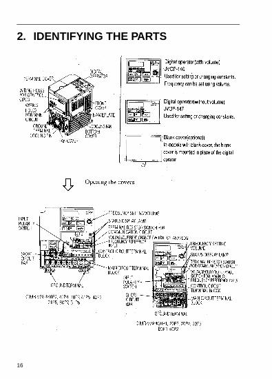
2. IDENTIFYING THE PARTS
) is
17
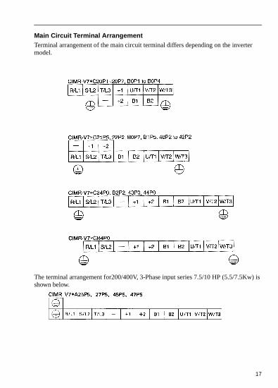
Main Circuit Terminal ArrangementTerminal arrangement of the main circuit terminal differs depending on the invertermodel.
The terminal arrangement for200/400V, 3-Phase input series 7.5/10 HP (5.5/7.5Kwshown below.

n
18
3. MOUNTING• Choosing a Location to Mount the InverterBe sure the inverter is protected from the following conditions:
• Extreme cold and heat. Use only within the ambient temperature range (for opechassis type): 14 to 122°F (-10 to +50°C).
• Rain, moisture.
• Oil sprays, splashes.
• Salt spray.
• Direct sunlight. (Avoid using outdoors).
• Corrosive gases (e.g. sulfurized gas) or liquids.
• Dust or metallic particles in the air.
• Physical shock, vibration.
• Magnetic noise. (Example: welding machines, power devices, etc.)
• High humidity.
• Radioactive substances.
• Combustibles: thinner, solvents, etc.

nd
19
• Mounting DimensionsTo mount the VS 606 V7, dimensions as shown below are required.
Caution!1. The above dimensions are common for both open chassis type (IP00, IP20) a
NEMA 1 type.
2. Always remove both top and bottom covers when using 200/400V, 5.5/7.5Kw(7.5/10 HP) as open chassis type.
Voltage
Max. ApplicableMotor Output
HP (Kw)Length of A
200V Single - phase 3 - phase400V 3 - phase
Less than 5 HP (3.7 Kw)
More than1.18in (30mm)
200V 3 - phase
400V 3 - phase
7.5 HP (5.5 Kw) More than1.97in (50mm)
10 HP (7.5 Kw)
A
aa

20
• Mounting/Removing ComponentsRemoving and Mounting Digital Operator and Covers
NOTE: Mount the inverter after removing the front cover, digital operator and terminal cover.
• Removing front coverUse a screwdriver to loosen the screw on the front cover surface to direction 1 to remove it. Then press the right and left sides to direction 2 and lift the front cover to direction 3.
• Mounting front coverMount the front cover in the reverse order of the above procedure for removal.
• Removing terminal cover when “W” (Width) dimensions are 4.25” (108mm), 5.51” (140mm), or 6.69” (170mm)After removing the front cover, press the right and left sides to direction 1 and lift the terminal cover to direction 2.
.• Removing terminal cover when “W”
(Width) dimensions are 7.09” (180mm) Use a Screwdriver to loosen the screw on the terminal cover surface to direction 1 to remove it. Then press the right and left sides to direction 2 and lift the terminal cover to direction 3.
• Mounting terminal coverMount the terminal cover in the descending order of the above procedure for removal.

21
• Removing digital operatorAfter removing the front cover, lift the upper and lower sides (section A) of the right side of the digital operator to direction 1.
• Mounting digital operatorMount the digital operator in the reverse order of the above procedure for removal.
• Removing bottom cover when “W” (Width) dimensions are 4.25” (108mm), 5.51” (140mm), or 6.69” (170mm)After removing the front cover and the terminal cover, tilt the bottom cover to direction 1 with section A as a supporting point.
• Removing terminal cover when “W” (Width) dimensions are 7.09” (180mm) After removing the terminal cover use a screwdriver to loosen the fastening screw to loosen the fastening screw to direction 1 to remove it.
• Mounting bottom coverMount the bottom cover in the reverse order of the above procedure for removal.

ver
put. inal
de
t
wer
CE
l.
22
4. WIRING• Wiring Instructions(1) Always connect the power input terminals R/L1, S/L2, and T/L3 (R/L1, S/L2 for
single-phase) and power supply via a molded-case circuit breaker (MCCB). Neconnect them to U/T1, V/T2, W/T3.
The single-phase (200V class) inverter can be connected to a 200V 3-phase inHowever, when terminal T/L3 is connected to single-phase, never use the termfor other purposes.
Inverter Power Supply Connection Terminals
(2) Connect the motor wiring to terminals U, V, and W on the main circuit output si(bottom of the inverter).
(3) If the wiring distance between inverter and motor is long, reduce the inverter carrier frequency. For details, refer to “Reducing motor noise or leakage curren(n46)” on page 68.
(4) Control wiring must be less than 164ft(50m) in length and separate from the powiring. Use twisted-pair shielded wire when inputting the frequency signal externally.
(5) Tighten the screws on the main circuit and control circuit terminals.
(6) Do not connect or disconnect wiring, or perform signal check while the power supply is turned ON.
(7) For 400V class inverters, make sure to ground the supply neutral to conform torequirements.
(8) A closed-loop connector should be used when wiring to the main circuit termina
(9) Voltage drop should be considered when determining wire size. Voltage drop can be calculated using the following equation: Phase- to phase voltage drop (V) = √3 wire resistance (Ω/km) x wiring distance (m) x current (A) x 10
Select a wire size so that voltage drop will be less than 2% of the normal ratedvoltage.
200V 3-phase Input Power Supply Specification ProductCIMR-V72
200V Single Input Power Supply Specification Product.CIMR-V7B
400V 3-phase Input Power Supply Specification ProductCIMR-V74
Connect to R/L1, S/L2, T/L3 Connect to R/L1, S/L2 Connect to R/L1, S/L2, T/L3
-3

23
• Wire and Terminal Screw Sizes1. Control Circuit
2. Main Circuit200V Class 3-phase Input Series
Note: The wire size is set for copper wires at 160°F (75°C)
Model Terminal Symbol ScrewTightening
Torquelb • in (N • m)
Wire
Applicable sizeRecommend
size Typemm2 AWG mm2 AWG
Common to
all models
MA, MB, MC M3 4.44 to 5.33(0.5 to 0.6)
twisted wire 0.5 to 1.25single 0.5 to 1.25
20 to 1620 to 16
0.75 18Shielded wire or
equivalentS1 to S7,P1, P2,SC,PC,R+,
R-,S+,S-,FS,FR,FC,AM,AC,RP
M2 1.94 to 2.21(0.22 to 0.25)
twisted wire 0.5 to 0.75single 0.5 to 1.25
20 to 1820 to 16 0.75 18
Model Terminal Symbol Screw
Tightening Torquelb • in
(N • m)
WireApplicable
sizeRecommended
size Typemm2 AWG mm2 AWG
CIMR-V7AA20P1R/L1,S/L2,T/L3,-,+1,+2,B1,B2,U/T1,V/T2,W/T3
M3.57.1 to 8.88(0.8 to 1.0)
0.75 to 218 to
142 14
600V vinyl-
sheathed wire or
equivalent
CIMR-V7AA20P2R/L1,S/L2,T/L3,-,+1,+2,B1,B2,U/T1,V/T2,W/T3
M3.57.1 to 8.88(0.8 to 1.0)
0.75 to 218 to
142 14
CIMR-V7AA20P4R/L1,S/L2,T/L3,-,+1,+2,B1,B2,U/T1,V/T2,W/T3
M3.57.1 to 8.88(0.8 to 1.0)
0.75 to 218 to
142 14
CIMR-V7AA20P7R/L1,S/L2,T/L3,-,+1,+2,B1,B2,U/T1,V/T2,W/T3
M3.57.1 to 8.88(0.8 to 1.0)
0.75 to 218 to
142 14
CIMR-V7AA21P5R/L1,S/L2,-,+1,+2,B1,B2,U/T1,V/T2,W/T3
M410.65 to 13.31
(1.2 to 1.5)2 to 5.5
14 to 10
2 14
CIMR-V7AA22P2R/L1,S/L2,T/L3,-,+1,+2,B1,B2,U/T1,V/T2,W/T3
M410.65 to 13.31
(1.2 to 1.5)2 to 5.5
14 to 10
3.5 12
CIMR-V7AA24POR/L1,S/L2,T/L3,-,+1,+2,B1,B2,U/T1,V/T2,W/T3
M410.65 to 13.31
(1.2 to 1.5)2 to 5.5
14 to 10
5.5 10
CIMR-V7*A25P5R/L1,S/L2,T/L3,-,+1,+2,B1,B2,U/T1,V/T2,W/T3
M522.19(2.5)
5.5 to 8 10 to 8 8 8
CIMR-V7*A27P5R/L1,S/L2,T/L3,-,+1,+2,B1,B2,U/T1,V/T2,W/T3
M522.19(2.5)
5.5 to 8 10 to 8 8 8

24
200V Class Single-phase Input Series
Note: The wire size is set for copper wires at 160°F (75°C)Note: Three-phase input is also available for 0.1 to 0.75kw of single-phase input
series.
400V Class 3-phase Input Series
Note: The wire size is set for copper wires at 160°F (75°C)
Model Terminal Symbol Screw
Tightening Torquelb • in
(N • m)
WireApplicable
sizeRecommended
size Typemm2 AWG mm2 AWG
CIMR-V7AAB0P1R/L1,S/L2,T/L3,-,+1,+2,B1,B2,U/T1,V/T2,W/T3
M3.57.1 to 8.88(0.8 to 1.0)
0.75 to 218 to
142 14
600V vinyl-sheathed wire or
equivalent
CIMR-V7AAB0P2R/L1,S/L2,T/L3,-,+1,+2,B1,B2,U/T1,V/T2,W/T3
M3.57.1 to 8.88(0.8 to 1.0)
0.75 to 218 to
142 14
CIMR-V7AAB0P4R/L1,S/L2,T/L3,-,+1,+2,B1,B2,U/T1,V/T2,W/T3
M3.57.1 to 8.88(0.8 to 1.0)
0.75 to 218 to
142 14
CIMR-V7AAB0P7R/L1,S/L2,T/L3,-,+1,+2,B1,B2,U/T1,V/T2,W/T3
M410.65 to 13.31
(1.2 to 1.5)2 to 5.5
18 to 14
3.5 12
CIMR-V7AAB1P5R/L1,S/L2,T/L3,-,+1,+2,B1,B2,U/T1,V/T2,W/T3
M410.65 to 13.31
(1.2 to 1.5)2 to 5.5
14 to 10
5.5 10
3.5 12
CIMR-V7AAB2P2R/L1,S/L2,T/L3,-,+1,+2,B1,B2,U/T1,V/T2,W/T3
M410.65 to 13.31
(1.2 to 1.5)2 to 5.5
14 to 10
5.5 10
CIMRV7AAB4PO
R/L1,S/L2,T/L3,-,+1,+2,B1,B2,U/T1,V/T2,W/T3 M526.62(3.0)
3.5 to 8 12 to
88 8
M410.65 to 13.31
(1.2 to 1.5)2 to 8
14 to 8
5.5 10
Model Terminal Symbol Screw
Tightening Torquelb • in
(N • m)
WireApplicable
sizeRecommended
size Typemm2 AWG mm2 AWG
CIMR-V7AA40P2R/L1,S/L2,T/L3,-,+1,+2,B1,B2,U/T1,V/T2,W/T3
M410.65 to 13.31
(1.2 to 1.5)2 to 5.5
14 to 10
2 14
600V vinyl-sheathed wire or
equivalent
CIMR-V7AA40P4R/L1,S/L2,T/L3,-,+1,+2,B1,B2,U/T1,V/T2,W/T3
M410.65 to 13.31
(1.2 to 1.5)2 to 5.5
14 to 10
2 14
CIMR-V7AA40P7R/L1,S/L2,T/L3,-,+1,+2,B1,B2,U/T1,V/T2,W/T3
M410.65 to 13.31
(1.2 to 1.5)2 to 5.5
14 to 10
2 14
CIMR-V7AA41P5R/L1,S/L2,T/L3,-,+1,+2,B1,B2,U/T1,V/T2,W/T3
M410.65 to 13.31
(1.2 to 1.5)2 to 5.5
14 to 10
2 14
CIMR-V7AA42P2R/L1,S/L2,T/L3,-,+1,+2,B1,B2,U/T1,V/T2,W/T3
M410.65 to 13.31
(1.2 to 1.5)2 to 5.5
14 to 10
2 14
CIMR-V7AA43P0 R/L1,S/L2,T/L3,-,+1,+2,B1,B2,U/T1,V/T2,W/T3M4
10.65 to 13.31(1.2 to 1.5)
2 to 5.514 to
102 14
3.5 12
CIMR-V7AA44PO R/L1,S/L2,T/L3,-,+1,+2,B1,B2,U/T1,V/T2,W/T3M4
10.65 to 13.31(1.2 to 1.5)
2 to 5.514 to
102 14
3.5 12CIMR-V7*A45P5 R/L1,S/L2,T/L3,-,+1,+2,B1,B2,U/T1,V/T2,W/T3
M412.43 (1.4)
3.5 to 5.512 to
105.5 10
CIMR-V7*A47P5 R/L1,S/L2,T/L3,-,+1,+2,B1,B2,U/T1,V/T2,W/T3M5
22.19(2.5)
5.5 to 812 to
105.5 10

25
• Wiring the Main Circuit
• Main circuit input power supplyConnect the power supply wiring to input terminals L1 (R), N/L2(S) and L3(T) [L1(R), N/L2(S) for single-phase specifications]. Never connect them to U/T1, V/T2, W/T3, B1, B2, -, +1, or +2. Otherwise the inverter may be damaged. Single-phase voltage may be connected to inverter but do not use terminal T/L3 for any other purposes.
• Grounding (Use ground terminal .)
Make sure to ground the ground terminal according to the local grounding code. Never ground the VS-606V7 in common with welding machines, motors, or other electrical equipment.
When several VS-606V7 units are used side by side, ground each unit as shown in examples. Do not loop the ground wires.
NOTE Single-phase (200V class, 0.75kW or less) voltage may be connected to terminal T/L3. Never use the ter-minal with other purposes.
• Braking resistor connection (optional).
To connect the braking resistor, cut the protector on terminals B1 and B2.
To protect the braking resistor from overheating, install a thermal overload relay between the braking resistor and theinverter. This provides a sequence which shuts off the power supply, by a thermal relay trip contact.
Use this same procedure when connectinga braking resistor unit. Refer to page 104.
• Inverter outputConnect the motor terminals to U, V, W.Wiring the main circuit terminals
Pass the cables through wiring hole and connect. Be sure to mount the cover in itsoriginal position.
[Example of 3-phase400V class, 0.37 inverters]
L1 L2 L3

n the
26
• Wiring the Control CircuitOnly basic insulation is provided for the control circuit terminals.
Additional insulation may be necessary in the end product.
• Control Circuit terminalsPass the cable through wiring hole and connect. Be sure to mount all the covers ooriginal position.
* SW1 can be changed according to sequence input signal (S1 to S7) polarity.0V common: NPN side (factory setting)24 common: PNP sideRefer to pages 67 and 76 for SW2
Wiring the control circuit terminals
Insert the wire into the lower part of the terminal block and connect it tightly with a screwdriver.
Wire sheath strip length must be 0.22 in. (5.5mm).
Screwdriver blade width

-
27
Open the front cover and verify that the strip length is 0.22 in. (5.5mm)
• Wiring InspectionAfter completing wiring, check the following:
• Wiring is properly connected.• Wire clippings or screws are not left inside the unit.• Screws are securely tightened.• Bare wires in the terminal do not come in contact with other terminals.
NOTE If the FWD (REV) run command is given during the operation reference selection (n003=1) from the control circuit terminal, the motor will start automaticallyafter the main circuit input power supply is turned ON.

ce l
y as
28
5. OPERATING THE INVERTERInitial setting of control mode selection (n002) is set at V/f control mode.
• Test RunThe inverter operates by setting the frequency (speed).
There are three types of operation modes for the VS-606V7:
1. Run command from the digital operator (local potentiometer/digital setting).
2. Run command from the control circuit terminal.
3. Run command from communications (MEMOBUS communications).
Prior to shipping, the drive is set up to receive run command and frequency referenfrom the operator. Below are instructions for running the VS-606V7 using the digitaoperator JVOP-140 (with local potentiometer) or optional JVOP-147 (without local potentiometer. For instructions on operation, refer to page 37.
Operation reference or frequency reference parameters can be selected separatelshown below.
Name parameter
Operation Reference Selection
N003 = 0 --- Enables operator RUN, STOP/RESET= 1 --- Enables control circuit terminal run/stop= 2 --- Enables communications (MEMOBUS communications)= 3 --- Enables communication card (optional)
Frequency Reference Selection
N004 = 0 --- Enables digital operator potentiometer= 1 --- Enables frequency reference 1 (parameter 024)= 2 --- Enables voltage reference (0 to 10V) of control circuit terminal= 3 --- Enables current reference (4 to 20mA) of control circuit terminal= 4 --- Enables current reference (0 to 20mA) of control circuit terminal= 5 --- Enables pulse line reference of control circuit terminal= 6 --- Enables communications (MEMOBUS communications)= 7 --- Enables voltage reference (0 to 10V) of operator circuit terminal= 8 --- Enables current reference (4 to 20 mA) of operator circuit terminal= 9 --- Enables communication card (optional)

29
Status indicator lamp
Operation Check Points• Motor rotates smoothly.• Motor rotates in the correct direction.• Motor does not have abnormal vibration or noise.• Acceleration or deceleration is smooth.• Current matching the load flows.• Status indicator LED’s and digital operator display are correct.
Operation StepsOperator Display
12-LED Display
Status Indicator LED
1. Turn ON the power supply. 6.00RUN
ALARM
2. Set parameter n004 to 1. 1 RUN
ALARM
3. Set the following parameters. n019 : 15.0 (acceleration time) n020 : 5.0 (deceleration time)
15.0 5.0
RUN
ALARM
4. F/R blinks.Select Forward or reverse run by pressing or key.
Examine the application.(Never select REV when reverse run is prohibited.)
(Forward) or
(Reverse)
RUN
ALARM
5. Set the reference by pressing or key. 60.00 RUN
ALARM
6. Press 0.00 60.0 RUN
ALARM
7. Press STOP to stop. 60.0 00.0 RUN
ALARM
NOTE
F /R
FOUT
: ON : Blinking :OFF: Blinking (Long Blinking)
PRGM
PRGM
FREF
FOUT
F R E F
RUN

of
30
• Operating the Digital OperatorAll functions of the VS-606V7 are set by the digital operator. Below are descriptionsthe display and keypad sections.
Digital Operator JVOP-140

ult
31
Description of Status Indicator LED’sThere are two LED’s on the middle right section of the face of the VS-606V7. The inverter status is indicated by various combinations of ON, BLINKING and OFF LED’s. RUN indicator and status indicator of the button have the same functions.
For details on how the status indicator LED’s function at inverter faults, refer to Section 8 “FAULT DIAGNOSIS AND CORRECTIVE ACTIONS” on page 126. If a fault occurs, the ALARM LED lights.
NOTE The fault can be reset by turning ON the fault reset signal (or pressing key
on the digital operator) with the operation signal OFF or by turning OFF the power supply. If the operation signal is ON, the fault cannot be reset by the fareset signal.
RUN
STOPRESET

32
• LED Description
By pressing on the digital operator, each of the function LED’s can be selected.
The following flowchart describes each function LED.
If the VS-606V7
loses power while in
one of these modes,
it will return to this
mode once power is
restored.

33
Return to
Multi-Function monitor
• Selecting monitor
Press key. When is ON, data can be displayed by selecting monitor No.
[Example] Monitoring Output Voltage Reference
41

when
s.100% or
34
• MonitoringFollowing items can be monitored by U-parameter
parameterNo.
Name Description
U-01Frequency reference
(FREF)*¹ HzFrequency reference can be monitored. (Same as FREF)
U-02Output frequency
(FOUT)*¹ HzOutput frequency can be monitored.(Same as FOUT)
U-03Output current
(IOUT)*¹ HzOutput current can be monitored.(Same as IOUT)
U-04 Output voltage V Output voltage can be monitored.U-05 DC voltage V Main circuit DC voltage can be monitored.
U-06 Input terminal status*2 —Input terminal status of control circuit terminals can be monitored.
U-07 Output terminal status*2 —Output terminal status of control circuit terminals can be monitored.
U-08 Torque monitor %The amount of output torque can be monitored. When V/f control mode is selected, “----” is displayed.
U-09 Fault history (last 4 faults) — Last four fault history is displayed.U-10 Software No. — Software No. can be checked.U-11 Output power*3 kW Output power can be monitored
U-13 Cumulative operation time*4 x10HCumulative operation time can be monitored in units of 10H
U-15 Data reception error*4 —Contents of MEMOBUS communication data reception error can be checked. (contents of transmission register No. 003DH are the same)
U-16 PID feedback*5 % Input 100(%) / Max. output frequency or equivalentU-17 PID input*5 % + 100(%) /+ Max. output frequency U-18 PID output*5 % + 100(%) /+ Max. output frequency
*1 The status indicator LED is not turned ON.
*2 Refer to the next page for input / output terminal status.
*3 The display range is from -99.9kW to 99.99kW. When regenerating. the output power will be displayed in units of 0.01kW -9.99kW or less and in units of 0.1kW when more than -9.99kW. When in the vector control mode, “----” will be displayed.*4 This function only applies to 200/400V class 7.5/10hp (5.5/7.5kW) inverter*5 Displayed in units of 0.1% when less than 100% and in units of 1% when more. The display range is from -999% to 999%.

35

to
36
Fault history display methodWhen U-09 is selected, a four-digit box is displayed. The three digits from the rightshow the fault description, and the digit on the left shows the order of fault (from onefour). Number 1 represents the latest fault, and 2, 3, 4, in ascending order of fault occurrence.
(Example)
(Refer to page 126 for details.)
• Switching fault history
Order of the fault history can be changed by or key.• Clearing fault history
Set parameter n001 to 6 to clear fault history. Display returns to n001 after completion of 6 setting.
Note: parameter initialize (n001 = 10, 11) clears the fault history.
Setting and referring parameters

g
37
• Simple Data SettingDigital setting (Refer to 5, OPERATING THE INVERTER) and potentiometer settinare both available for simple accel/decel operation of the VS-606V7.
Frequency reference by analog voltage is set with initial setting (n004 = 1). For themodel with digital operator (with potentiometer) JVOP-140, factory setting is set byfrequency setting potentiometer (n004=0).
Following is an example in which the function LED’s are used to set frequency reference, acceleration time, deceleration time, and motor direction.
Data setting by frequency setting potentiometer
Status indicator lamp
Operation StepsOperator Display
12-LED Display
Status Indicator LED
1. Turn the potentiometer fully to the left. Then, turn the power ON.
0.00 RUN
ALARM
2. F/R blinks. Select FWD/REV run using keys.
Never select REV when reverse run is prohibited.
FOR or REV
RUN
ALARM
3. Press DSPL to blink FREF. Then press RUN. 0.00 RUN
ALARM
4. Operates the motor by turning the potentiometer to the right. (Frequency reference corresponds to the potentiometer position is displayed.)
If the potentiometer is switched rapidly, the motor also accelerates or decelerates rapidly corresponding to the potentiometer movement. Pay attention
to load status and switch the potentiometer movement.
00.0 to 60.00Minimum output frequency is 1.50Hz
RUN
ALARM
FREF
F/R
FREF
NOTE
FREF
: ON : Blinking :OFF: Blinking (Long Blinking)
NOTE

38
Notes

39
6. PROGRAMMING FEATURESFactory settings of the parameters are shown as in the tables.
• Parameter Set-up and Initialization
The following table describes the data which can be set or read when n001 is set.
Unused parameters among n001 to n179 are not displayed.
* Excluding setting disabled parameters.= Refer to page 70.
(1) The set values of input terminal function selection 1 to 7 (n050 to n056) are the same.
(2) The following conditions are not satisfied in the V/f pattern setting:Max. output frequency (n011) > Max. voltage output frequency (n013) > Mid. output frequency (n014) > Min. output frequency (n016)For details, refer to “Adjusting torque according to application” (V/f pattern set-ting) on page 38.
(3) If the following conditions are not satisfied in the Jump frequency setting:Jump frequency 3 (n085)< Jump frequency 2 (n084)
< Jump frequency 1 (n083)
(4) If Frequency reference lower limit (n034) > Frequency reference upper limit (n033)
(5) If motor rated current (n036) > 150% of inverter rated current
(6) When n018 = 0 and n019 ~ n022 is set to a value greater than 600.0 sec, parameter n018 will automatically be set to 1.
Parameter selection/initialization (n001)
n001 Setting Parameter that can be set Parameter that can be referred0 n001 n001 to n1791 n001 to n049* n001 to n0492 n001 to n079* n001 to n0793 n001 to n119* n001 to n1194 n001 to n179* n001 to n1795 Not used6 Fault history cleared8,9,12,13 Not used10 Initialize 11 Initialize (3-wire sequence)=
NOTE “ ” appears on the LED display for one second and the set data returns to its initial values in the following cases:
40
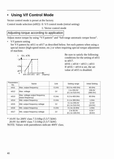
• Using V/f Control ModeVector control mode is preset at the factory.
Control mode selection (n002): 0: V/f control mode (initial setting)
1: Vector control mode
Adjust motor torque by using “V/f pattern” and “full-range automatic torque boost”.
• V/f pattern settingSet V/f pattern by n011 to n017 as described below. Set each pattern when using a special motor (high-speed motor, etc.) or when requiring special torque adjustment of machine.
Be sure to satisfy the following conditions for the setting of n011 to n017.n016 < n014 < n013 < n011If n016 = n014 is set, the set value of n015 is disabled.
Adjusting torque according to application
Parameters No.
Name Unit Setting range Initial Setting
n011 Max. output frequency 0.1Hz 50.0 to 400.0Hz 60.0Hz
n012 Max. voltage 1V1 to 255.0V
(0.1 to 510.0V)230.0V
(460.0V)
n013Max. voltage output frequency (base frequency)
0.1Hz 0.2 to 400.0Hz 60.0Hz
n014 Mid. output frequency 0.1Hz 0.1 to 399.9Hz 1.5Hz
n015 Mid. output frequency voltage 1V0.1 to 255.0V
(0.1 to 510.0V)12.0V
(24.0V)n016 Min. output frequency 0.1Hz 0.1 to 10.0Hz 1.5Hz
n017 Min. output frequency voltage 1V1 to 50.0V
(0.1 to 100.0V)4.3V *(8.6V)
n016 n014 n013 n011 (frequency)
* 10.0V for 200V class 7.5/10hp (5.5/7.5kW) 20.0V for 400V class 7.5/10hp (5.5/7.5kW)NOTE: Values with parentheses indicate 400V class.

41
• Typical setting of V/f patternSet the V/f pattern according to the application as described below. For 400V class, the voltage values (n012, n015, and n017) should be doubled. When running at a frequency exceeding 50Hz/60Hz, change the maximum output frequency (n011).
Note: Be sure to set the maximum output frequency according to the motor char-acteristics
Increasing voltage of V/f pattern increases motor torque, but excessive increase may cause motor over excitation, motor overheat, or vibration.
Note: n012 is to be set to motor rated voltage.
(Factory setting)

42
• Full-range automatic torque boost (when V/f mode is selected. n002=0)Motor torque requirement changes according to load conditions. Full range automatic torque boost adjusts voltage of V/f pattern according to the requirement. The VS-606V7 automatically adjusts the voltage during parameter-speed operation as well as during acceleration.The required torque is calculated by the inverter.This ensures tripless operation and energy-saving effects.
• Operation
Normally, no adjustment is necessary for torque compensation gain (n103 factory setting: 1.0). An excessively high setting of torque compensation gain will result in motor over excitation, and possible inverter faults. If adjustments are necessary, adjust n103 in increments/decrements of 0.1 for optimization. When wiring distance between the inverter and the motor are long it may be necessary to increase the setting of n103. When motor generates vibration, decrease the setting of n103.
Adjustment of torque compensation time parameter (n104) and torque iron loss compensation parameter (n105) are normally not required.
Adjust torque compensation parameter under the following conditions:
• Increase setting when the motor generates vibration.• Reduce setting when motor response is low.
Output voltage Torque compensation gain (n103) Required torque∝ ×
43
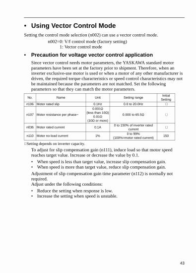
• Using Vector Control ModeSetting the control mode selection (n002) can use a vector control mode.
n002=0: V/f control mode (factory setting)1: Vector control mode
• Precaution for voltage vector control applicationSince vector control needs motor parameters, the YASKAWA standard motor parameters have been set at the factory prior to shipment. Therefore, when an inverter exclusive-use motor is used or when a motor of any other manufacturer is driven, the required torque characteristics or speed control characteristics may not be maintained because the parameters are not matched. Set the following parameters so that they can match the motor parameters.
∗ Setting depends on inverter capacity.
To adjust for slip compensation gain (n111), induce load so that motor speed reaches target value. Increase or decrease the value by 0.1.
• When speed is less than target value, increase slip compensation gain.• When speed is more than target value, reduce slip compensation gain.
Adjustment of slip compensation gain time parameter (n112) is normally not required.Adjust under the following conditions:
• Reduce the setting when response is low.• Increase the setting when speed is unstable.
No. Name Unit Setting rangeInitial
Settingn106 Motor rated slip 0.1Hz 0.0 to 20.0Hz ∗
n107 Motor resistance per phase=
0.001Ω(less than 10Ω)
0.01Ω(10Ω or more)
0.000 to 65.5Ω ∗
n036 Motor rated current 0.1A0 to 150% of inverter rated
current∗
n110 Motor no-load current 1%0 to 99%
(100%=motor rated current)150

44
Select slip compensation status during regeneration
• Motor parameter calculationThe following shows an example of motor parameter calculation:
(1) Motor rated slip (n106)
(2) Motor resistance for one phase (n107)Calculations are based on line-to-line resistance and insulation grade of the motor test report.
(E type insulation) Test report of line-to-line resistance at 75°C (Ω) x 0.92 x 1/2
(B type insulation) Test report of line-to-line resistance at 75°C (Ω) x 0.92 x 1/2
(F type insulation) Test report of line-to-line resistance at 115°C (Ω) x 0.87 x 1/2
(3) Motor rated current (n036)
= Rated current at motor rated frequency (Hz) *1 (A)
(4) Motor no-load current (n110)
*1 Base frequency (Hz) during rated output current. *2 Rated speed (r/min) at base frequency during rated output current.
Set n106 (motor rated slip), n036 (motor rated current), n107 (motor resistance per phase) and n110 (motor no-load current) according to the motor test report.
When connecting a reactor between the inverter and the motor, set n108 to the value of n108 (motor leaking inductance) initial value + externally-mounted reactor inductance. Initial setting should be used unless a reactor is installed.
Unless a reactor is connected, n108 (motor leakage inductance) does not have to be set according to the motor.
N113 Setting Slip Compensation during Regeneration0 Disabled1 Enabled
120 motor rated frequency (Hz)× *1
Number of motor pole--------------------------------------------------------------------------------------------- Motor rated speed (r/min)
*2–
120/Number of motor pole----------------------------------------------------------------------------------------------------------------------------------------------------------------------------=
No-load current (A) at motor rated frequency (Hz)*1
Rated current (A) at motor rated frequency (Hz)*1
---------------------------------------------------------------------------------------------------------- 100%×=

45
• V/f pattern during vector controlSet V/f pattern as follows during vector control.The following examples are for 200V class motors. When using 400V class motors, double voltage settings (n012, n015, n017).
When operating with frequency larger than 60Hz/50Hz, change only maximum output frequency (n011).
= 50Hz
PARAMETER OUTPUT PARAMETER TORQUE VARIABLE OUTPUT

46
• Switching LOCAL/REMOTE ModesThe following functions can be selected by switching the LOCAL or REMOTE mode. To select RUN/STOP commands or frequency reference, change the mode in advance depending on the following applications.
• LOCAL mode:Enables the digital operator for RUN/STOP commands andFWD/REV run commands. Frequency reference can be set by
local potentiometer or .• REMOTE mode: Enables operation reference selection (n003).
• How to select LOCAL/REMOTE modes

47
• Selecting Run/Stop CommandsRefer to Switching LOCAL/REMOTE Modes (Page 44) to select either the LOCAL mode or REMOTE mode.Operation method (RUN / STOP commands, FWD / REV run commands) can be selected by the following method.
• LOCAL Mode
When Lo (local mode) is selected by digital operator ON mode, or when the LOCAL / REMOTE switching function is set and the input terminals are
turned ON, run operation is enabled by the or of the digital operator,
and FWD/REV run is selected by ON mode (using or key).
• REMOTE mode• Select remote mode.
The following two methods are used to select remote mode:
1. Select rE (remote mode) by selection.
2. When the local / remote switching function is selected by multi-function input selection, turn OFF the input terminal to select remote mode.
• Select operation method by setting the parameter n003.n003 =0: Enables the digital operator (same with local mode)
=1: Enables the multi-function input terminal (see fig. below)=2: Enables communications
=3: Enables communication card (optional)
• Example for using the multi-function input terminal as operation reference (two-wire sequence)
Below shows the example of three-wire sequence, (Refer to page 70.)
For example of three-wire sequence, refer to page 70Note: When inverter is operated without the digital operator, always set the
parameter n010 to 0.
)
48
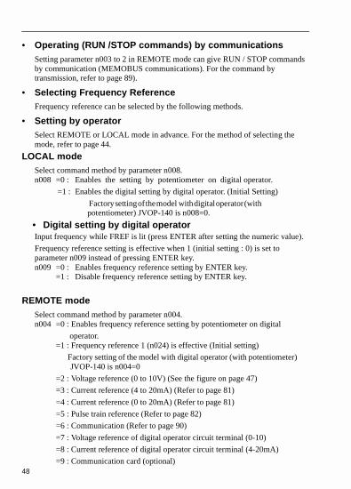
• Operating (RUN /STOP commands) by communicationsSetting parameter n003 to 2 in REMOTE mode can give RUN / STOP commands by communication (MEMOBUS communications). For the command by transmission, refer to page 89).
• Selecting Frequency ReferenceFrequency reference can be selected by the following methods.
• Setting by operatorSelect REMOTE or LOCAL mode in advance. For the method of selecting the mode, refer to page 44.
LOCAL modeSelect command method by parameter n008.n008 =0 : Enables the setting by potentiometer on digital operator.
=1 : Enables the digital setting by digital operator. (Initial Setting)
Factory setting of the model with digital operator (with potentiometer) JVOP-140 is n008=0.
• Digital setting by digital operatorInput frequency while FREF is lit (press ENTER after setting the numeric value).
Frequency reference setting is effective when 1 (initial setting : 0) is set to parameter n009 instead of pressing ENTER key.n009 =0 : Enables frequency reference setting by ENTER key.
=1 : Disable frequency reference setting by ENTER key.
REMOTE modeSelect command method by parameter n004.n004 =0 : Enables frequency reference setting by potentiometer on digital
operator. =1 : Frequency reference 1 (n024) is effective (Initial setting)
Factory setting of the model with digital operator (with potentiometer) JVOP-140 is n004=0
=2 : Voltage reference (0 to 10V) (See the figure on page 47)
=3 : Current reference (4 to 20mA) (Refer to page 81)
=4 : Current reference (0 to 20mA) (Refer to page 81)
=5 : Pulse train reference (Refer to page 82)
=6 : Communication (Refer to page 90)
=7 : Voltage reference of digital operator circuit terminal (0-10)
=8 : Current reference of digital operator circuit terminal (4-20mA)
=9 : Communication card (optional)

49
Example of frequency reference by voltage signal
1)

50
• Setting Operation Conditions
“Reverse run prohibit” setting does not accept a reverse run command from the control circuit terminal or digital operator. This setting is used for applications where a reverse run command can cause problems.
By combining frequency reference and input terminal function selections, up to 16 steps of speed can be set.
8-step speed change
Reverse run prohibit (n006)
Setting Description0 Reverse run enabled1 Reverse run disabled
Multi-step speed selection
n003=1 (operation mode selection)n004=1 (Frequency reference selection)n024=25.0Hz (Frequency reference 1)n025=30.0Hz (Frequency reference 2)n026=35.0Hz (Frequency reference 3)n027=40.0Hz (Frequency reference 4)n028=45.0Hz (Frequency reference 5)n029=50.0Hz (Frequency reference 6)n030=55.0Hz (Frequency reference 7)n031=60.0Hz (Frequency reference 8)
NOTE When all multi-step speed inputs are open, frequency reference selected by parameter n004 (frequency reference selection) becomes effective.
Only when multi-step speed input ref. 1 is closed and n077=1, the effective frequency reference becomes the CN2 analog input signal.
n054=6 (Multi-function contact input terminal 5)n055=7 (Multi-function contact input terminal 6)n056=8 (Multi-function contact input terminal 7)n053=1
n050=1 (Input terminal S1 ) Initial Settingn051=2 (Input terminal S2 ) Initial Settingn052=3 (Input terminal S3) Initial Settingn053=5 (Input terminal S4 ) Initial Settingn054=6 (Input terminal S5 ) Initial Settingn055=7 (Input terminal S6 ) Initial Settingn056=10 (Input terminal S7 ) Change the Setting to 8
51
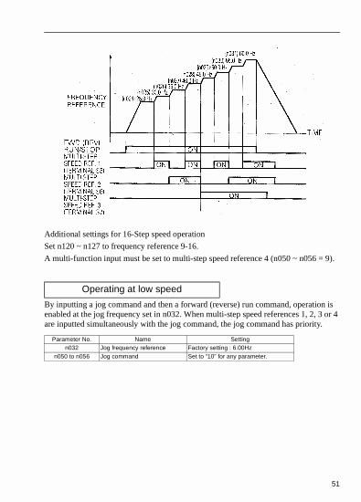
Additional settings for 16-Step speed operation
Set n120 ~ n127 to frequency reference 9-16.
A multi-function input must be set to multi-step speed reference 4 (n050 ~ n056 = 9).
By inputting a jog command and then a forward (reverse) run command, operation is enabled at the jog frequency set in n032. When multi-step speed references 1, 2, 3 or 4 are inputted simultaneously with the jog command, the jog command has priority.
Operating at low speed
Parameter No. Name Settingn032 Jog frequency reference Factory setting : 6.00Hz
n050 to n056 Jog command Set to “10” for any parameter.

52
• Adjusting speed setting signalTo provide frequency reference by analog input of control circuit terminal FR and FC, the relationship between analog input and frequency reference can be set.
(a) Analog frequency reference gain (n060)
The frequency reference provided when analog input is 10V(20mA) can be set in units of 1%. (maximum output frequency n011=100%)
∗ Factory setting : 100%
(b) Analog frequency reference bias (n061)
The frequency reference provided when analog input is 0V (4mA or 0mA) can be set in units of 1%. (Maximum output frequency n011=100%)
∗ Factory setting : 0%
Typical setting
• To operate the inverter with frequency reference of 0% to 100% at 0 to 5V input
FREQUENCY REFERENCE

53
• To operate the inverter with frequency reference of 50% to 100% at 0 to 10V input

54
*When “deceleration to a stop” is selected (n005=0).
By setting “Multifunction Input Selection” (either of n050 to n056) to “11 (accel/decel time select)”, accel/decel time is selected by turning ON/OFF the accel/decel time select (terminal S1 to S7).At OFF : n019 (accel time 1)
n020 (decel time 1)At ON : n021 (accel time 2)
n022 (decel time 2)
Adjusting frequency upper and lower limits• Frequency reference upper limit (n033)
Sets the upper limit of the frequency reference in units of 1%.(n011: Maximum output frequency = 100%)Factory setting: 100%
• Frequency reference lower limit (n034)Sets the lower limit of the frequency reference in units of 1%.(n011: Maximum output frequency = 100%)When operating at frequency reference 0, operation is continued at the frequency reference lower limit. However, when frequency reference lower limit is set to less than the minimum output frequency (n016), operation is not performed.Factory setting: 0%
Using two accel/decel times

55
n018 setting
Notes: Parameter n018 can be set during stop. If the numeric value exceeded 600.0 sec. is set for the accel/decel time when n018 = 0 (in units of 0.1 sec.). “1” cannot be set to n018.
• Accel timeSet the time needed for output frequency to reach 100% from 0%.
• Decel timeSet the time needed for output frequency to reach 0% from 100%.
(Maximum output frequency n011 = 100%)
When parameter n081 is set to 1 or 2, operation automatically restarts even if momentary power loss occurs.
* Hold the operation command to continue the operation after recovery from a momentary power loss.
= When 2 is selected, the inverter restarts if power supply voltage recovers while the control power supply is held.No fault signal is output.
No. Name Unit Setting Range Initial settingn019 Accel time 1
Refer to n018
setting
Refer to n018 setting
10.0sn020 Decel time 1 10.0sn021 Accel time 2 10.0sn022 Decel time 2 10.0s
No. Unit Setting Range
n0180
0.1s 0.0 - 999.9s (999.9s or less)1s 1000 - 6000s (1000s or more)
10.01s 0.00 - 99.99s (99.99s or less)0.1s 100.0 - 600.0s (100s or more)
Automatic restart after momentary power loss (n081)
Setting. Description0 Continuous operation after momentary power loss not provided.
1*Continuous operation after power recovery within momentary power loss ride thru time 0.5s.
2*=Continuous operation after power recovery (Fault output not provided)

56
To prevent shock at machine start/stop, accel/decel can be performed in S-curve pattern.
Note: The S-curve characteristics time is the time from accel/decel rate 0 to a reg-ular accel/decel rate determined by the set accel/decel time.
The following time chart shows FWD/REV run switching at deceleration to a stop.
Soft-start characteristics (n023)
Setting S-curve characteristic time0 S-curve characteristic not provided1 0.2 second2 0.5 second3 1.0 second

57
If an excessive load is applied to the machine, the resultant output current increase can be compared to the threshold setting of parameter n098, then output alarm signals to multi-function output terminals MA, MB, P1 and P2.
To output an overtorque detection signal, set output terminal function selection n057 to n059 to “overtorque detection” [Setting:6 (NO contact) or 7 (NC contact)].
∗ Overtorque detection release width (hysterisis) is set at approx. 5% of inverter rated current.
Torque detection

58
• Overtorque detection function selection 1 (n096)
(1) To detect overtorque at accel/decel, set to 3 or 4.
(2) To continue the operation after overtorque detection, set to 1 or 3.
During detection, the operator displays “ ” alarm (blinking).
(3) To halt inverter by a fault at overtorque detection, set to 2 or 4. At detection, the
operator displays “ ” fault (ON).
• Overtorque detection level (n098)Sets the overtorque detection current level in units of 1%. (Inverter rated current = 100%) When detection by torque is selected, motor rated torque becomes 100%.Factory setting: 160%
• Overtorque detection time (n099)If the time when the motor current exceeds the overtorque detection current level (n098) is longer than overtorque detection time (n099), the overtorque detection function operates.Factory setting: 0.1sec.
• Overtorque detection function selection 2 (n097)When vector control mode is selected, overtorque detection can be performed either by output current or by output torque.When V/f control mode is selected, n097 setting becomes invalid, and overtorque is detected by output current.
Setting Description0 Overtorque detection not provided
1Detected during parameter-speed running, and operation continues after detection.
2Detected during parameter-speed running, and operation stops during detection.
3Detected during running, and operation continues after detection.
4Detected during running, and operation stops during detection.
Setting Description0 Detected by output torque1 Detected by output current

59
Effective when either of output terminal function selections n057, n058 or n059 are set to “frequency detection” (setting: 4 or 5). “Frequency detection” turns ON when output frequency is higher or lower than the frequency detection level (n095).
• Frequency detection1
Output frequency > Frequency detection level n095(Set either of n057, n058 or n059 to “4”.)
• Frequency detection2
Output frequency < Frequency detection level n095(Set either of n057, n058 or n059 to “5”.)
Frequency detection (n095)

60
This function allows the prohibition or “jumping” of critical frequencies so that the motor can operate without resonance caused by machine systems. This function is also used for dead band control. Setting the value to 0.00Hz disables this function.
Set prohibited frequency 1, 2 or 3 as follows:
Operation is prohibited within jump frequency range.
However, motor operates smoothly (without jumping) during accel/decel.
Sets the inverter to restart and reset fault detection after a fault occurs.
The number of self-diagnosis and retry attempts can be set at n082 up to 10.
The inverter automatically restarts after the following faults occur:
• OC (over current)• OV (over voltage)
The number of retry attempts are cleared to 0 during the following cases:
(1) If no other fault occurs within 10 minutes after retry
(2) When the fault reset signal is ON after the fault is detected
(3) Power supply is turned OFF
Jump frequencies (n083 to n086)
n083 > n084 > n085If this condition is not satisfied the inverter displays for one second and restores the data to original settings.
Continuing operation by automatic fault reset (n082)

61
• Cumulative Operation Time Selection (n087)
Cumulative operation time setting.
Inverter operating time set with parameter n087 is accumulated by the unit of 10H.
Accumulation starts from the time set with parameter n088.
• Installed Braking Resistor Overheating protection Selection (n165) Set “0” when braking resistor is not connected.
Setting Description
0Inverter power-on time
(Counts the elapsed time that there is an inverter output)
1Inverter running time
(Counts the elapsed time that there is an inverter output.)
Parameter No. Name Unit Setting RangeInitial
Setting
n088 Cumulative operation 1 = 10H 0 to 6550 (65500H) 0 (H)
Setting Description
0 Overheating protection is not provided
1 Overheating protection is provided

62
• Input / Output Open Phase Protection
*1 0% setting - no detection
*2 0.0 sec setting - no detection
• Recommended set values: 7% for n166
10sec. for n167
5% for n168
0.2sec. for n169
Parameters No.
Name UnitSetting Range
Initial Setting
n166Input open-phase
detection level1%
0 to 100% *1 400.0V/100%
(for 200V class)800.0V/100%
(for 400V class)
0%
n167Input open-phase
detection time1 sec. 0 to 255 sec. *2 0 sec.
n168Output open-phase
detection level1%
0 to 100% *1 Inverter rated output current value/100%
0%
n169Output open-phase
detection time0.1 sec. 0.0 to 2.0 sec *2 0.0 sec.

63
• Speed search commandRestarts a coasting motor without stopping it. This function enables smooth switching between motor commercial power supply operation and inverter operation.
Set input terminal function selection (n050 to n056) to “14” (search command from maximum output frequency) or “15” (search command from set frequency).
Build a sequence so that FWD (REV) run command is input at the same time as the search command or after the search command. If the run command is input before the search command, the search command becomes disabled.
• Time chart at search command input
Set declaration time during a speed search at parameter n101. Speed search starts when inverter output current > speed search operation level.This function applies to the 200/400V class 7.5/10hp inverters.

64
To hold acceleration or deceleration, input accel/decel hold command. The output frequency is maintained when the accel/decel hold command is input during acceleration or deceleration.
When the stop command is input during accel/decel prohibition command input, accel/decel hold is released and operation ramps to stop.
Set multi-function input terminal selection (n050 to n056) to 16 (accel/decel hold command).
Holding accel/decel temporarily

65
Selects the function to be monitored at analog output terminals AM-AC.
In initial setting, analog voltage of approx. 10V is output when output frequency (output current) is 100%.
Used to adjust analog output gain.
Set the analog output voltage at 100% of output frequency (output current). Frequency meter displays 0 to 60Hz at 0 to 3V.
Using frequency meter or ammeter (n066)
Setting Description0 Output frequency1 Output current2 Main circuit DC voltage3 Torque monitor4 Output power5 Output voltage reference
Calibrating frequency meter or ammeter (n067)
10V n067 Setting0.30
× 3V=
Output frequency becomes
100% at this value
…

66
Analog output AM-AC can be used as a pulse train output (output frequency monitor).
Set n065 to 1 when using pulse train output.
n065 setting
Pulse train signal can be selected by setting n150.
At the factory setting the pulse of 1440Hz can be output when output frequency is 100%
Pulse monitor output can be adjusted with the parameter n067.
Using analog output (AM-AC) as a pulse train signal output (n065)
Parameters No. Name Unit Setting range Initial Settingn065 Monitor output type selection 1 0,1 0
n065 Setting0 Analog monitor output
1Pulse monitor output
(Output frequency monitor)
n150 Setting Description0 1440Hz / Max. frequency (n011)1 1F: Output frequency x 16 6F: Output frequency x 6
12 12F: Output frequency x 1224 24F: Output frequency x 2436 36F: Output frequency x36

67
Used as a sourcing output
Used as a sinking input
NOTE Peripheral devices must be connected according to the following load conditions when using pulse monitor output. The machine might be damaged when the con-ditions are not satisfied.
Output voltageVRL (V)
Load impendance(kΩ)
+5V 1.5 kΩ or more
+8V 3.5 kΩ or more
+8V 10 kΩ or more
External power supply (V) +12VDC+5%
Sinking current (mA) 16mA or less
68
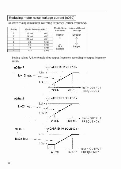
Set inverter output transistor switching frequency (carrier frequency).
Setting values 7, 8, or 9 multiplies output frequency according to output frequency value.
Reducing motor noise leakage current (n080)
Setting Carrier Frequency (kHz)Metallic Noise
from MotorNoise and Current
Leakage7 12 fout (Hz)8 24 fout (Hz)9 36 fout (Hz)1 2.5 (kHz)2 5.0 (kHz)3 7.5 (kHz)4 10.0 (kHz)
Higher
Notaudible
Smaller
Larger
fout = O U TP U TF R E Q U E N C Y
fou t = O U TP U TFR E Q U E N C Y
fout = O U T P U TF R E Q U E N C Y

69
Reducing Motor Noise or Leakage Current (n080)Frequency setting varies according to inverter capacity (kVA).
(1) Reduce continuous output current when changing carrier frequency to 4 (10kHz) for the 200V class (1.5 W or more) and 400V class invert-ers. Refer to the table above for the reduced current.
[Operation Condition]
•Input power supply voltage : 3-phase 200 to 230 V (200V class) Single-Phase 200 to 240V (200V class)3-Phase 380 to 460V (400V class)
•Ambient temperature: 14 to 122ºF (-10 to +50ºC) (Protection structure: open chassis type IP20)
(2) If the wiring distance is long, reduce the inverter carrier frequency as described below
Voltage Class (V)Capacity
(kW)
Initial Setting Maximum Continuous
Output Current (A)
Reduced Current (A)Setting
Carrier Frequency
200 Single-phase 3-
phase
0.1 4 10kHz 0.8
–0.2 4 10kHz 1.60.4 4 10kHz 3.00.7 4 10kHz 5.01.5 3 7.5kHz 8.0 7.02.2 3 7.5kHz 11.0 10.03.7 3 7.5kHz 17.5 16.55.5 3 7.5kHz 25 237.5 3 7.5kHz 33 30
400 3-phase
0.2 3 7.5kHz 1.2 1.00.4 3 7.5kHz 1.8 1.60.7 3 7.5kHz 3.4 3.01.5 3 7.5kHz 4.8 4.02.2 3 7.5kHz 5.5 4.83.0 3 7.5kHz 7.2 6.33.7 3 7.5kHz 8.6 8.15.5 3 7.5kHz 14.8 *7.5 3 7.5kHz 18 17
Wiring Distance between
Inverter and MotorUp to 50m Up to 100m More than 100m
Carrier frequency
(n080 setting)
10kHz or less
(n080=1, 2, 3, 4, 7, 8, 9)
5kHz or less
(n080=1, 2, 7, 8, 9)
2.5kHz or less
(n080=1, 7, 8, 9,)

70
(3) Set carrier frequency (n080) to either 1, 2, 3, 4 when using vector con-trol mode. Do not set to 7, 8, or 9.
(4) Carrier frequency is automatically reduced to 2.5kHz when reducing carrier frequency selection at low speed (n175) is set to 1 and the fol-lowing conditions are satisfied:
Output frequency < 5 Hz
Output current > 110%
Factory setting : 0 (Disabled)
Selects processing when STOP key is pressed during operation either from multi-func-tion input terminal or communications.
Operator stop key selection (n007)
Setting Description
0
STOP key effective when running either from multi-function input terminals or communications. When STOP key is pressed, the inverter stops according to the setting of the parameter n005. At this time, the digital operator displays “ “ alarm (blinking). This stop command is held in the inverter until both forward and reverse run commands are open, or until run command from communications becomes zero.
1STOP key is ineffective when running either from multi-function input terminals or communications.

71
Selects the stopping method suitable for application.
• Deceleration to stopExample: when accel/decel time 1 is selected
Upon termination of the FWD (REV) run command, the motor decelerates at the decel rate determined by the time set to decel time 1 (n020) and DC injection braking is applied immediately before stop. DC injection braking is also applied when the motor decelerates by setting frequency reference lower than minimum output frequency (n016) with FWD (REV) run command ON.
If the decel time is short or the load inertia is large, over voltage (OV) fault may occur at deceleration. In this case, increase the decel time or install a optional braking resistor.
Braking Torque: Without braking resistor: Approx. 20% torque of motor ratingWith braking resistor: Approx. 150% torque of motor rating
Selecting stopping method (n005)
Setting Description0 Deceleration to stop1 Coast to stop
* When frequency reference is changed during running.
.5
.0

72
• Coast to stopExample: when accel/decel time 1 is selected
Upon removal of the FWD (REV) run command, the motor starts coasting.
• DC injection braking current (n089)Sets DC injection braking current in units of 1%. (Inverter rated current=100%)
• DC injection braking time at stop (n090)Sets the DC injection braking time at stopping in units of 0.1 second. When the setting of n090 is 0, DC injection braking is not performed but inverter output is shut OFF at the timing of DC injection braking start.
When coasting to a stop is specified in stopping method selection (n005), DC injection braking at stop does not operate.
Applying DC injection braking
* When frequency reference is changed during running.

73
• Building Interface Circuits with External Devices
Multi-function input terminal S1 to S7 functions can be changed when necessary by setting parameters n051 or n052 respectively. The same value cannot be set to different parameter settings.
* Numbers 1 to 7 are displayed in q corresponding to the terminal number S1 to S7 respectively.
Using input signals
Setting Name Description Ref.
0 FWD/REV run command(3 wire sequence selection) Setting enabled only for n052 74
1 Forward run(2 wire sequence selection) 45
2 Reverse run(2 wire sequence selection) 45
3 External fault (NO contact input) Inverter stops by external fault signal input
Digital operator display is EF D .*–
4 External fault (NC contact input) –
5 Fault Reset Resets the fault. Fault reset not effective with the run signal ON. 50
6 Multi-step speed reference 1 507 Multi-step speed reference 2 508 Multi-step speed reference 3 509 Multi-step speed reference 4 50
10 JOG command 5111 Accel/Decel time select 54
12 External baseblock(NO contact input)
Motor coast to a stop by thissignal input.
Digital operator display is
bb.
–
13 External baseblock(NC contact input) –
14 Search command from maximum frequency Speed search
reference signal
63
15 Search command from set frequency 63
16 Accel/decel hold command 6417 LOCAL/REMOTE selection 46
18 Communication/control circuitterminal selection 78
19 Emergency stop fault(NO contact input)
Inverter stops by emergency stop signal input according to stopping method selection (n005). When frequency coasting to a stop (n005 is set to 1) method is selected, inverter coasts to a stop according to decel time setting 2 (n022).
Digital operator display is sRp
(lit at fault, blinking at alarm).
–
20 Emergency stop alarm(NO contact input) –
21 Emergency stop fault(NC contact input) –
22 Emergency stop alarm(NC contact input) –
23 PID Control cancel 11424 PID integral reset 114
26 Inverter overheat prediction OH3“ “ (Blinking) is displayed on the digital operator by signal input
25 PID intregal hold 114
34 UP/DOWN command Setting enabled only forn056 (terminal S7) 75
35 Self-test Setting enabled only forn056 (terminal S7) 114
74
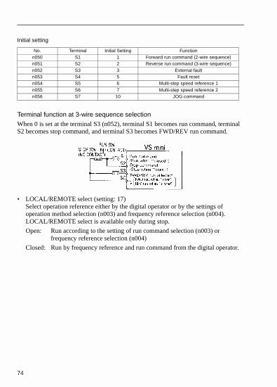
Initial setting
Terminal function at 3-wire sequence selectionWhen 0 is set at the terminal S3 (n052), terminal S1 becomes run command, terminal S2 becomes stop command, and terminal S3 becomes FWD/REV run command.
• LOCAL/REMOTE select (setting: 17)Select operation reference either by the digital operator or by the settings of operation method selection (n003) and frequency reference selection (n004). LOCAL/REMOTE select is available only during stop.
Open: Run according to the setting of run command selection (n003) or frequency reference selection (n004)
Closed: Run by frequency reference and run command from the digital operator.
No. Terminal Initial Setting Functionn050 S1 1 Forward run command (2-wire sequence)n051 S2 2 Reverse run command (3-wire sequence)n052 S3 3 External faultn053 S4 5 Fault resetn054 S5 6 Multi-step speed reference 1n055 S6 7 Multi-step speed reference 2n056 S7 10 JOG command

75
(Example:)Set n003 = 1, n004 = 2, n008 = 0.
Open: Run by frequency reference from multi-function input terminal FR and run command from multi-function input terminals S1 to S7.
Closed: Run by potentiometer frequency reference and run command from the digital operator.
• UP/DOWN command (setting: n056 = 034)With the FWD (REV) run command entered, accel/decel is enabled by inputting the UP or DOWN signals to multi-function input terminals S6 and S7 without changing the frequency reference, so that operation can be performed at the desired speed. When UP/DOWN commands are specified by n056, any function set to n055 becomes disabled; terminal S6 becomes an input terminal for the UP command and terminal S7 for the DOWN command.
Multi-function Input Terminal S6 (UP command)
Closed Open Open Closed
Multi-function Input Terminal S7 (DOWN command)
Open Closed Open Closed
Operation Status Accel Decel Hold Hold

76
Time Chart at UP/DOWN Command Input
77
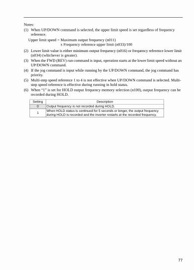
Notes:(1) When UP/DOWN command is selected, the upper limit speed is set regardless of frequency
reference.
(2) Lower limit value is either minimum output frequency (n016) or frequency reference lower limit (n034) (whichever is greater).
(3) When the FWD (REV) run command is input, operation starts at the lower limit speed without an UP/DOWN command.
(4) If the jog command is input while running by the UP/DOWN command, the jog command has priority.
(5) Multi-step speed reference 1 to 4 is not effective when UP/DOWN command is selected. Multi-step speed reference is effective during running in hold status.
(6) When “1” is set for HOLD output frequency memory selection (n100), output frequency can be recorded during HOLD.
Setting Description0 Output frequency is not recorded during HOLD.
1When HOLD status is continued for 5 seconds or longer, the output frequency during HOLD is recorded and the inverter restarts at the recorded frequency.
Upper limit speed = Maximum output frequency (n011)x Frequency reference upper limit (n033)/100

78
• Communication/multi-function input terminal selection input (setting: 18)
Operation can be changed from communication command, or from multi-function input terminal or digital operator command.
Run command from communication and frequency reference are effective when multi-function input terminal for this setting is “closed (register No. 0001H, 0002H).”Run command in LOCAL/REMOTE mode and frequency reference are effective when “Open.”
The input analog signal (0 to 10V or 4mA to 20mA) for the CN2 terminal of the JVOP-140 digital operator can be used as an auxiliary function for the main speed frequency reference input to the control circuit terminals (FR or RP). Refer to the
block diagram on page 111 for details of the input signal.
Multi-function input selection (n077)
Using multi-function analog input (n077, n078, n079)
NOTE When using the signal for the CN2 terminal of the JVOP-140 digital operator’s a multi-function analog input, never use it or the target value or the feedback value of PID control. (PID control is disabled when n128 is set to 0.)
No. Name UnitSetting Range
Initial Setting
n077Multi-functioninput selection
_ 0 to 4 0

79
n077 settingSetting Name Description
0 Disabled The multi-function input is disabled
1
Auxiliary frequency reference (FREF2)
When frequency reference 2 is selected in multi-stepspeed reference, the input analog signal for the CN2 terminal becomes the frequency reference. The n025 setting becomes invalid. Note: Set frequency reference gain to n068 or n071, and frequency reference bias to n069 or no72.
2Frequency reference gain (FGAIN)
Provides gain to main frequency reference.
3
Frequency reference (FBIAS)
Set the FGAIN to parameter n60 or n074 and the FBIAS to parameter n061 or n075 for the main speed frequencyreference. Then, add the FBIAS to the resulting frequency reference.The amount of the FBIAS to be added is set to n79.
4 Frequency detectionAdd the VBIAS to the output voltage after V/f conversion.

80
Analog input level
The VBIAS value to be added is doubled for 400V class inverters.
Frequence reference bias (n077=3) Output voltage bias (n077=4)
FREF2Auxiliary frequency reference (n077=1)
FGAIN Frequency reference gain (n077=2)

81
Multi-function analog input signal selection (n078)
Frequency reference bias setting (n079)
Parameter No. Name UnitSetting Range
Initial Setting
n078 Multi-function analog input signal selection
_
0 = Digital operator terminal (voltage: 0 to 10V) 1 = Digital operator terminal (current: 4 to 20mA)
0
Parameter No. Name UnitSetting Range
Initial Setting
n079 Frequency reference bias setting
%0 to 50
100% / Max. output frequency(n011)
10
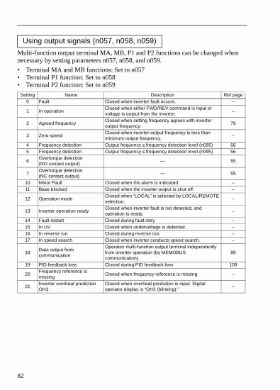
82
Multi-function output terminal MA, MB, P1 and P2 functions can be changed when necessary by setting parameters n057, n058, and n059.
• Terminal MA and MB functions: Set to n057• Terminal P1 function: Set to n058• Terminal P2 function: Set to n059
Using output signals (n057, n058, n059)
Setting Name Description Ref page0 Fault Closed when inverter fault occurs. –
1 In operationClosed when either FWD/REV command is input or voltage is output from the inverter.
–
2 Agreed frequencyClosed when setting frequency agrees with inverter output frequency.
79
3 Zero speedClosed when inverter output frequency is less than minimum output frequency.
–
4 Frequency detection Output frequency ≥ frequency detection level (n095) 565 Frequency detection Output frequency ≤ frequency detection level (n095) 56
6Overtorque detection (NO contact output)
— 55
7Overtorque detection (NC contact output)
— 55
10 Minor Fault Closed when the alarm is indicated. –11 Base blocked Closed when the inverter output is shut off. –
12 Operation modeClosed when “LOCAL” is selected by LOCAL/REMOTE selection.
–
13 Inverter operation readyClosed when inverter fault is not detected, and operation is ready.
–
14 Fault restart Closed during fault retry –15 In UV Closed when undervoltage is detected. –16 In reverse run Closed during reverse run. –17 In speed search Closed when inverter conducts speed search. –
18Data output from communication
Operates multi-function output terminal independently from inverter operation (by MEMOBUS communication).
89
19 PID feedback loss Closed during PID feedback loss 109
20Frequency reference is missing
Closed when frequency reference is missing –
21Inverter overheat prediction OH3
Closed when overheat prediction is input. Digital operator display is “OH3 (blinking).”
–

83
• Setting Frequency by Current Reference Input
Initial setting of multi-function output terminal
NOTE Never input voltage reference to control circuit terminal FR when DIP switch SW2 is switched to “I” side. This could damage the inverter.
No. Terminals Initial Settingn057 MA, MB 0 (fault)n058 P1 1 (in operation)n059 P2 2 (Frequency agreed)
When setting frequency by inputting current reference (4-20mA or 0-20mA) from the control circuit terminal FR, switch the DIP switch SW1 on the control circuit board to “I” side.
SW1 is accessed by removing the digital operator.

84
Current reference selection
After changing DIP switch (V/I switch of SW2) to the “I” side, PRESS on the digital operator, then set the following parameters.
Current reference (4-20mA) parameter n004=3
Current reference (0-20mA) parameter n004=4
Frequency reference gain (n060)/bias (n061) can be set even when current reference input is selected. For details, refer to “Adjusting frequency setting signal” on page 81.
PRGM
Press the digital operator keys to run or stop the inverter. Switch run and stop direction by setting F/R LED.
Set frequency by the analog current signal [0-100% (max frequency)/4-20mA] connected to the control circuit terminal.
Set run/stop and FWD/REV run with switching device connected to the control circuit terminal.
Multi-function input terminals S1 and S2 are set to Forward run / STOP (n050 = 1) and Reverse run/stop (n051 = 2) respectively.
Set frequency by the analog current signal [0-100% (max. frequency)/4-20mA] connected to the control circuit terminal.

85
• Frequency Reference by Pulse Train InputFrequency reference can be set by pulse train input from the multi-function input terminal.
• Input pulse specifications• Low-level voltage: 0.8V or less• High-level voltage: 3.5 to 32V• Duty Cycle: 30 to 70%• Pulse frequency: 0 to 33 kHz
• Frequency reference methodFrequency reference is a value obtained by multiplying the ratio of the maximum input pulse frequency and actual input pulse frequency by the maximum output frequency.
ParameterNo.
Name Unit Setting range Initial Setting
n003 Run command selection 1 0 to 2 0n004 Frequency reference selection 1 0 to 6 0
n149 Pulse train input scaling 1=10Hz 1100 to 3300
(33kHz)2500
(25kHz)
Reference freqInput pulse frequency
Minimum pulse train frequency (n149) 10×----------------------------------------------------------------------------------------------------------------- max output frequency (n011)×=
Run/stop and FWD/REV can be selected by a switch connected to the control circuit terminal.
Frequency setting can be set by pulse train input signal [0 to 100% (maximum frequency)/0 to 33kHz] connected to the multi-function input terminal.

86
Automatically adjusts the output frequency and output current according to the load to continue operation without stalling the motor.
• Stall prevention (current limit) level during acceleration (n093)Sets the stall prevention (current limit) level during acceleration in units of 1% (Inverter rated current = 100%).
Factory setting: 170%
A setting of 200% disables the stall prevention (current limit) during acceleration. During acceleration, if the output current exceeds the value set for n093, acceleration stops and frequency is maintained. When the output current goes down to the value set for n093, acceleration starts.
In the constant horsepower area [output frequency > max. voltage output frequency (n013)], the following equation automatically decreases the stall prevention (current limit) level during acceleration, but the stall prevention level will never go below 40% of n093.
Preventing Motor from Stalling (Current Limit)
* Stops the acceleration to prevent the motor from stalling.
† Release width (hysteresis) of stall prevention during accel is approx. 5% of inverter rated current.

87
• Stall prevention (current limit) level during running (n094)Sets the stall prevention (current limit) level during running in units of 1% (Inverter current = 100%).
• Factory setting: 160%
A setting of 200% disables the stall prevention (current limit) during running.
If the inverter is at speed agree and output current exceeds the value set for n094 for longer than 100msec, deceleration starts.
Deceleration continues until the output current falls below the value set for n094. When this occurs, the inverter will accelerate back up to the set frequency.
Stall prevention accel/decel settings during operation are set either by accel time 1 (n019) and decel time 1 (n020), or accel time 2 (n021) and decel time 2 (n022).
• Stall prevention automatic decrease selection (n115)
The stall prevention level can be increased automatically in the parameter output range.
Stall prevention during operation
Parameter No.
Name Unit Setting RangeInitial
Setting
n115Stall prevention automatic decrease selection
-0=Disabled1=Enabled
0
* Decreases frequency to prevent the motor from stalling.
† At acceleration start, output hysteresis is approx. 5% of inverter rated current.

88
n115 setting
• Accel/decel time selection during stall prevention (n116)With this function, acceleration/deceleration time when moving to prevent stalling during operations can be assigned to the two parameters, n021 and n022.
n116 setting
• Stall prevention (current limit) function during acceleration (n092)To prevent over voltage during deceleration, the inverter automatically extends the deceleration time according to the value of the main circuit DC voltage. When using an optional braking resistor, set n092 to 1.
Setting Function0 The stall prevention level becomes the level set for the parameter n094 in all frequency areas
1
The following shows that the stall prevention level is automatically decreased in the parameter output range (Max. frequency>Max. voltage output frequency).The lower limit is 40% of the set value of n094.
Parameter No.
Name Unit Setting Range Initial Setting
n116Accel/decel time selection during stall prevention
-0=Disabled1=Enabled
0
Setting Function0 Accel/decel time is set by accel/decel time 1or 2.1 Accel/decel time is fixed at accel/decel time 2(n021, n022)
SettingStall prevention (current limit) during
deceleration0 Provided1 Not provided (when braking resistor is mounted

89
• Decreasing Motor Speed Fluctuation
As the load becomes larger, motor speed is reduced and motor slip value is increased. The slip compensating function controls the motor speed at a parameter value even if the load varies.
When inverter output current is equal to the motor rated current (n036), the compensation frequency is added to the output frequency.
Related Parameters
* Differs depending on inverter capacity.
Notes: 1. Slip compensation is not performed in the following condition:Output frequency < minimum output frequency (n016).
2. Slip compensation is not performed during regeneration.
3. Slip compensation is not performed when motor rated current (n036) is set to 0.0A.
Slip compensation (When V/f control mode n002=0)
ParametersNo.
Name Unit Setting RangeInitial
Setting
n036 Motor rated current 0.1A 0 to 150% of inverter rated current *
n111 Slip compensation gain 0.1 0.0 to 2.5 0.0
n110 Motor no-load current 1% 0 to 99% (100% = Motor rated current n036) *
n112Slip compensation primary delay time
0.1s0.0 to 25.5sWhen 0.0s is set, delay time becomes 2.0s.
2.0s
n106 Motor rated slip 0.1Hz 0.0 to 20Hz *
Compensation frequency Motor rated slip (n106)=
Output current Motor no-load current (n110)–
Electronic thermalreference current (n036) Motor no-load current (n110)–---------------------------------------------------------------------------------------------------------------------------------------------------×
Slip compensation gain (n111)×
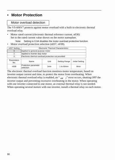
90
• Motor Protection
The VS-606V7 protects against motor overload with a built-in electronic thermal overload relay.
• Motor rated current (electronic thermal reference current, n036)Set to the rated current value shown on the motor nameplate.
Note: Setting to 0.0A disables the motor overload protective function.• Motor overload protection selection (n037, n038).
The electronic thermal overload function monitors motor temperature, based on inverter output current and time, to protect the motor from overheating. When electronic thermal overload relay is enabled, an “ ” error occurs, shutting OFF the inverter output and preventing excessive overheating in the motor. When operating with one inverter connected to one motor, an external thermal relay is not needed. When operating several motors with one inverter, install a thermal relay on each motor.
Motor overload detection
n037 Setting Electronic Thermal Characteristics0 Applied to general-purpose motor1 Applied to inverter duty motor2 Electronic thermal overload protection not provided
Parameters No.
Name Unit Setting Range Initial Setting
n038Protection parameter selection
1min 1 to 60min 8min

91
• General-purpose motor and inverter duty motorInduction motors are classified as general-purpose motors or inverter motors, based on their cooling capabilities. Therefore, the motor overload function operates differently between these two motor types.
Example of 200V class motor
Cooling Effect Torque CharacteristicsElectronic Thermal overload
Gen
eral
-pur
pose
Mot
or
Effective when operated at 50/60Hz from commercial power supply
Base Frequency 60Hz(V/f for 60Hz, 220V Input Voltage)
For low-speed operation, torque must be limited in order to stop motor temperature rise.
error (motor
overload protection) occurs when continuously operated at 50/60Hz or less at 100% load.
Inve
rter
Mo
tor
Effective even when operated at low speed (approx. 6Hz)
Base Frequency 60Hz(V/f for 60Hz, 220V Input Voltage)
Use an inverter motor for continuous operation at low speed.
Electronic thermal overload protection not activated even when continuously operated at 50/60Hz or less at 100% load.

92
• Selecting Cooling Fan OperationIn order to increase lifetime, the cooling fan can be set to operate only when inverter is running.
• Using MEMOBUS (MODBUS) CommunicationsSerial transmission is available with VS-606V7 using programmable controller (MEMOCON series) and MEMOBUS.
• MEMOBUS (MODBUS) communicationsMEMOBUS system is composed of a single master (PLC) and slaves (1 to 31 VS-606V7 units).Communication between master and slave (serial communication) is controlled according to the master program with the master initiating communication and the slave responding.The master sends a signal to one slave at a time. Each slave has a pre-registered address No., and the master specifies the number and conducts signal communication. The slave receives the communications to carry out designated functions and reply to the master.
• Communications specifications
n039 = 0 (factory setting) : Operates only when inverter is running.(Continuous operation for 1 minute after inverter is stopped.)
1 : Operates with power ON.
Interface RS-422, RS485Synchronization Asynchronous (Start-stop synchronization)
Communication parameters
Baud rate: Selected from 2400/4800/9600/19200 bpsData length: 8bit fixedParity: Selected from even/odd/noneStop bits: 1bit fixed
Communication protocol
MEMOBUS (MODBUS) (RTU mode only)
Max. number of inverters that can be connected
31 units (When using RS-485

93
• Communications connection terminalUse the following S+, S-, R+ and R- terminals for MEMOBUS communications. Change the termination resistor as shown below.
At RS-422, RS-485 communications: Turn ON SW2 ON/OFF switch of only the inverter at the termination viewed from the PLC.
• Procedure for communications with PLCThe following shows the procedure for communications with PLC.
(1) Connect the communication cable between the PLC and the VS-606V7 with the power supply turned OFF.
(2) Turn the power ON.
(3) Set the parameters (n151 to n157) required for communication by using the digital operator.
(4) Turn the power OFF once to verify that the digital operator displays have been completely erased.
(5) Turn the power ON again.
(6) Communications with the PLC starts.
Notes: 1. Separate the wiring for communication from the main circuit wiring or other power lines.
2. Use shielded cables for communication wiring; connect the shielded sheath to the ground terminal and terminate the other end to prevent it from being connected (to prevent noise malfunction).
3. When communication is performed through RS-485, connect S+ and R+, S- and R- terminals outside the inverter as shown right side.

94
• Setting necessary parameters for communicationCommunication related parameters must be set for PLC communication. parameters n151 to n157 cannot be set during communication. Always set them prior to performing communication.
* The slave does not respond to the command from the master when set to 0.
Monitoring run status from the PLC, setting/referencing of parameters, fault reset and multi-function input reference can be done regardless of run command or frequency reference selection.
Multi-function input reference from PLC becomes OR with input commands from S1 to S7 multi-function input terminals.
Parameter Name DescriptionInitial
Setting
n003 Run command selection
0 : operator1 : control circuit terminals2 : communication3 : communication card (optional)
0
n004Frequency reference selection
0 : Local potentiometer (digital operator)1 : frequency ref. 1 (n024)2 : control circuit terminals (voltage 0 to 10V)3 : control circuit terminals (current 4 to 20mA)4 : control circuit terminals (current 0 to 20mA)5 : pulse train6 : MEMOBUS communication (Register No. 000211)7 : operator circuit terminals (voltage 0 to 10V)8 : operator circuit terminals (current 4 to 20mA)9 : communication card (optional)
0
n151
Timeover detection selection Monitors transmission time between the receiving the correct data from the PLC (Timeover: 2 sec)
0 : timeover detection (free run stop)1 : timeover detection (coasting to a stop with speed
reduction time 1)2 : timeover detection (coasting to a stop with speed
reduction time 2)3 : timeover detection (continuous operation, warning
display) 4 : timeover detection not provided
0
n152Communication frequencyReference monitor unit selection
0 : 0.1Hz1 : 0:0.1Hz2 : 30000/100% (30000 = max. output frequency)3 : 0.1%
0
n153 Slave address Setting range: 0 to 32* 0
n154 Baud rate selection
0 : 2400 bps1 : 4800 bps2 : 9600 bps3 : 19200 bps
2
n155 Parity selection0 : even parity1 : odd parity2 : no parity
0
n156 Sending waiting time Setting limit: 10 ms to 65 ms setting unit: 1 ms 10 ms
n157 RTS control0 : RTS control 1 : no RTS control (RS-422A 1 to 1 communication)
0
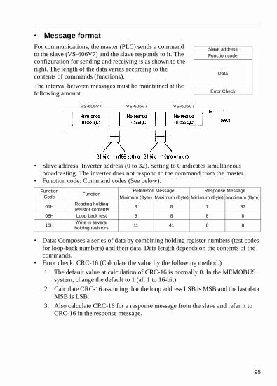
95
• Message formatFor communications, the master (PLC) sends a command to the slave (VS-606V7) and the slave responds to it. The configuration for sending and receiving is as shown to the right. The length of the data varies according to the contents of commands (functions).
The interval between messages must be maintained at the following amount.
• Slave address: Inverter address (0 to 32). Setting to 0 indicates simultaneous broadcasting. The inverter does not respond to the command from the master.
• Function code: Command codes (See below).
• Data: Composes a series of data by combining holding register numbers (test codes for loop-back numbers) and their data. Data length depends on the contents of the commands.
• Error check: CRC-16 (Calculate the value by the following method.)
1. The default value at calculation of CRC-16 is normally 0. In the MEMOBUS system, change the default to 1 (all 1 to 16-bit).
2. Calculate CRC-16 assuming that the loop address LSB is MSB and the last data MSB is LSB.
3. Also calculate CRC-16 for a response message from the slave and refer it to CRC-16 in the response message.
FunctionCode
FunctionReference Message Response Message
Minimum (Byte) Maximum (Byte) Minimum (Byte) Maximum (Byte)
01HReading holding resistor contents
8 8 7 37
08H Loop back test 8 8 8 8
10HWrite in severalholding resistors
11 41 8 8
Slave addressFunction code
Data
Error Check
VS-606V7 VS-606V7 VS-606V7

96
• Read out holding register contents [03H]Reads out the contents of the holding registers with the continuous numbers for the specified quantity. The contents of holding register is divided into the upper 8 bits and the lower 8 bits. They become the data items in response message in the order of numbers.Example: Reads out status signal, fault contents, data link status and frequency reference from the VS-606V7 (slave 2).
* Twice as much as the number of reference message.
• Example of loop-back test [08H]Command message is returned as a response message without being changed. This function is used to check transmission between the master and the slave. Any arbitrary values can be used for test codes or data.Example: Loop-back test of slave 1 and VS-606V7
Reference message(at normal operation)
(For error code 03H, refer to page 99.)
Response message(at normal operation)
Reference message(at fault occurrence)
Slave address 02H
Function code 03H
Start number
Upper 00H
Lower 20H
QuantityUpper 00H
Lower 04H
CRC-16Upper 45H
Lower F0H
Slave address 02H
Function code 03H
Number of data* 08H
First holding resistor
Upper 00H
Lower 65H
Next holding resistor
Upper 00H
Lower 00H
Next holding resistor
Upper 00H
Lower 00H
Next holding resistor
Upper 1H
Lower F4H
CRC-16Upper AFH
Lower 82H
Slave address 02H
Function code 83H
Error code 03H
CRC-16Upper F1H
Lower 31H
Reference message(at normal operation)
Response message(at normal operation)
Reference message(at fault occurrence)
Slave address 01H
Function code 08H
Start number
Upper 00H
Lower 00H
QuantityUpper A5H
Lower 37H
CRC-16Upper DAH
Lower 8DH
Slave address 01H
Function code 08H
Start number
Upper 00H
Lower 00H
QuantityUpper A5H
Lower 37H
CRC-16Upper DAH
Lower 8DH
Slave address 01H
Function code 89H
Error code 01H
CRC-16Upper 86H
Lower 50H

97
• Writing to several holding registers [10H]Specified data are written into the several specified holding registers from the specified number, respectively. Written data must be arranged in a command message in the order of the holding register numbers: from upper eight bits to lower eight bits.
Example: Set forward run at frequency reference 60.0 Hz to slave 1 VS-606V7 from the PLC.
* Sets twice as large as the actual number.
Reference message(at normal operation)
Response message(at normal operation)
Reference message(at fault occurrence)
Slave address 01H
Function code 10H
Start number
Upper 00H
Lower 01H
QuantityUpper 00H
Lower 02H
Number of data* 04H
First Data
Upper 00H
Lower 01H
Next data
Upper 02H
Lower 58H
CRC-16Upper 63H
Lower 39H
Slave address 01H
Function code 10H
Start number
Upper 00H
Lower 01H
QuantityUpper 00H
Lower 02H
CRC-16Upper 10H
Lower 08H
Slave address 01H
Function code 89H
Error code 01H
CRC-16Upper 86H
Lower 50H
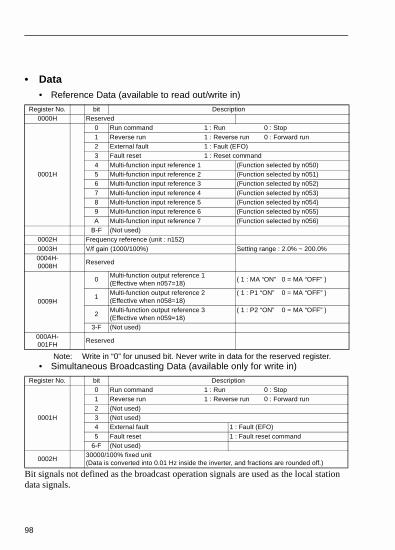
98
• Data• Reference Data (available to read out/write in)
Note: Write in “0” for unused bit. Never write in data for the reserved register.• Simultaneous Broadcasting Data (available only for write in)
Bit signals not defined as the broadcast operation signals are used as the local station data signals.
Register No. bit Description0000H Reserved
0001H
0 Run command 1 : Run 0 : Stop1 Reverse run 1 : Reverse run 0 : Forward run2 External fault 1 : Fault (EFO)3 Fault reset 1 : Reset command4 Multi-function input reference 1 (Function selected by n050)5 Multi-function input reference 2 (Function selected by n051)6 Multi-function input reference 3 (Function selected by n052)7 Multi-function input reference 4 (Function selected by n053)8 Multi-function input reference 5 (Function selected by n054)9 Multi-function input reference 6 (Function selected by n055)A Multi-function input reference 7 (Function selected by n056)
B-F (Not used)0002H Frequency reference (unit : n152)0003H V/f gain (1000/100%) Setting range : 2.0% ~ 200.0%0004H-0008H
Reserved
0009H
0Multi-function output reference 1(Effective when n057=18)
( 1 : MA “ON” 0 = MA “OFF” )
1Multi-function output reference 2(Effective when n058=18)
( 1 : P1 “ON” 0 = MA “OFF” )
2Multi-function output reference 3(Effective when n059=18)
( 1 : P2 “ON” 0 = MA “OFF” )
3-F (Not used)000AH-001FH
Reserved
Register No. bit Description
0001H
0 Run command 1 : Run 0 : Stop1 Reverse run 1 : Reverse run 0 : Forward run2 (Not used)3 (Not used)4 External fault 1 : Fault (EFO)5 Fault reset 1 : Fault reset command
6-F (Not used)
0002H30000/100% fixed unit(Data is converted into 0.01 Hz inside the inverter, and fractions are rounded off.)

99
• Monitor Data (available only for read out)
Register No. bit Description
0020HS
tatu
s si
gnal
0 Run command 1 : Run 0 : Stop1 Reverse run 1 : Reverse run 0 : Forward run2 Inverter operation ready 1 : Ready 0 : Not ready3 Fault 1 : Fault4 Data setting error 1 : Error5 Multi-function output 1 (1 : MA ON 0 : MA OFF)6 Multi-function output 2 (1 : P1 ON 0 : OFF)7 Multi-function output 3 (1 : P2 ON 0 : OFF)
8-F (Not used)
0021H
Fau
lt de
scrip
tion
0 Over current (OC)1 Over voltage (OV)2 Inverter overload (OL2)3 Inverter overheat (OH)4 (Not used)5 (Not used)6 PID Feedback loss (FbL)7 External fault (EF, EFO) Emergency stop (STP)8 Hardware fault (Fxx)9 Motor overload (OL1)A Overtorque detection (OL3)B (Not used)C Power loss (UV1)D Control power fault (UV2)E MEMOBUS communications timeover (CE)F Operator connection (OPR)
0022H
Dat
a lin
k st
atus
0 Data write in1 (Not used)2 (Not used)3 Upper/lower limit fault4 Consistency fault
5-F (Not used)0023H Frequency reference (Unit : n152)0024H Output frequency (Unit : n152)
0025H-026H (Not used)0027H Output current (10/1A)0028H Output voltage reference (1/1V)
0029H
Fau
lt co
nte
nts
0 Load short circuit (SC)1 Ground fault (GF)2 Input open phase (PF)3 Output open phase (LF)4 Installed type braking resistor overheat5 Braking transistor fault (RR)
6-F Not used

Register No. bit Description
002AH
Ala
rm C
onte
nts
0 Operator stop (STP)1 Sequence error (SER)2 FWD - REV command simulation input (EF)3 External baseblock (BB)4 Overtorque detection (OL3)5 Cooling fin overheat (OH)6 Main circuit overvoltage (OV)7 Main circuit undervoltage 8 Cooling fan fault (FAN)9 Communication errorA Option card communication error (BUS)B Not usedC Inverter overheat prediction (OH3)D PID feedback loss (FBL)E Emergency stop (STP)F Communication waiting (CALL)
002BH
Seq
uen
ce in
put
0 Terminal S1 1 : Closed O : Open1 Terminal S2 1 : Closed O : Open2 Terminal S3 1 : Closed O : Open3 Terminal S4 1 : Closed O : Open 4 Terminal S5 1 : Closed O : Open5 Terminal S6 1 : Closed O : Open6 Terminal S7 1 : Closed O : Open
7-F (Not Used)
002CH
Inve
rter
sta
tus
0 Run 1 : Run1 Zero - speed 1 : Zero - speed2 Frequency agreed 1 : Agreed3 Minor fault (Alarm is indicated)4 Frequency detection 1 1: Output frequency ≤ (n095)5 Frequency detection 2 1 : Output frequency ≥ (n095)6 Inverter operation ready 1 : Ready7 Undervoltage detection 1 : Under Voltage detection8 Baseblock 1 : Inverter output base block
9 Frequency reference mode1 : Other than communications0 : Communications
A Run command mode1 : Other than communications0 : Communications
B Overtorque detection 1 : Detection or overtorque faultC (Not used)D Fault restartE Fault (Including MEMOBUS communications timeover) 1 : FaultF MEMOBUS communications timeover 1 : Timeover
002DH
0 MA “ON” 1 : Closed 0 : Open1 P1 “ON” 1 : Closed 0 : Open2 P2 “ON” 1 : Closed 0 : Open
3-F(Not used)
100

101
* Communications error contents are saved until fault reset is input. (Reset is enabled during run.)
Register No. bit Description
02EHIn
vert
er S
tatu
s
0 Frequency ref. loss1 Not used2 Not used3 Not used4 Not used5 Not used6 Not used7 Not used
8 - F Not used002FH-0030H Reserved
0031H Main circuit DC voltage (1/1V)0032H Torque monitor
0033H-0034H Not used0035H Cumulative operation time (I/IH)0036H Not used
Register No. bit Description0037H Output power (1/1W : with sign)0038H PID feedback value (100% / Input equivalent to max. output frequency; 10/1%; without sign)
0039H PID input value (±100% / ± Max. output frequency ; 10/1%; with sign)003AH PID output value (±100% / ± Max. output frequency ; 10/1%; with sign)
003BH-003CH Reserved
003DH
Com
mun
icat
ions
err
or
0 CRC error1 P1 “ON”2 (Not used)3 Parity error4 Overrun error5 Framing error6 Timeover7 (Not used)
003EH-00FFH Reserved

102
• Storing parameters [Enter command] (can be written only.)
When a parameter is written from the PLC by communications, the parameter is written to the parameter data area on the RAM in the VS-606V7. ENTER command is a command to write the parameter data on the RAM to the non-volatile memory in the VS-606V7. Writing data (can be undefined) to register number 0900H during stop executes this ENTER command.
Maximum number of writing times of the non-volatile memory used for VS-606V7 is 100,000; do not execute the ENTER command excessively. When a parameter is changed from the digital operator, the parameter data on the RAM is written to the non-volatile memory without ENTER command.
Register number 0900H is used only for write-in. If this register is readout, register number error (error code: 02H) occurs.
RegisterNumber
Name Contents Setting Range Default
0900HENTER
commandWrite-in parameter data to non-
volatile memory (EEPROM).0000H to FFFFH -

103
Error Codes
* Refer to the parameters list for parameters that can be changed during operation.
Error Code Contents
01HFunction code error• Function code from PLC is other than 03H, 08H or 10H.
02HImproper register number• No register numbers to be accessed have been registered.• ENTER command “0900H” that is an exclusive-use register for write-in was read out.
03H
Improper quantity• The number of data items to be read or write-in is not in the range between 1 and 16.• The number of data items in a message is not the value obtained by multiplying the
quantity by two in the write-in mode.
21HData setting error• A simple upper/lower limit error occurred with control data or parameter write-in.• A parameter setting error occurred when a parameter was written.
22H
Write-in mode error• Attempt to write-in a parameter from PLC was made during running.• Attempt to write-in an ENTER command from PLC was made during running.• Attempt to write-in a parameter from PLC was made during UV occurrence.• Attempt to write-in an ENTER command from PLC was made during UV occurrence.• Attempt to write-in a parameter other than n001=12,13 (initialization) from PLC was
made during “F04” occurrence.• Attempt to write-in a parameter from PLC was made while data were being stored.• Attempt to write-in data exclusive for read-out from PLC was made.

104
• Performing self-testVS-606V7 is provided with a function to perform self-diagnosis for operation check of the serial communication I/F circuit. This function is called self-test. In the self-test, connect the sending terminal with the receiving terminal in the communication section. It assures if the data received by VS-606V7 is not being changed. It also checks if the data can be received normally. Carry out the self-test in the following procedure.
(1) Turn ON the VS-606V7 mini power supply. Set parameter n056 to 35 (self-test).
(2) Turn OFF the VS-606V7 mini power supply.
(3) Make the following wiring with the power supply turned OFF.
(4) Turn the power ON.
Normal operation: Operator displays frequency reference value.
Faulty operation: Operator displays “ ”, fault signal is turned ON and inverter ready signal is turned OFF.
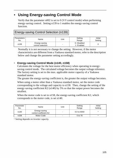
tion
nce.
mes.
the e
105
• Using Energy-saving Control ModeVerify that the parameter n002 is set to 0 (V/f control mode) when performing energy-saving control. Setting n139 to 1 enables the energy-saving control function.
Normally it is not necessary to change the setting. However, if the motor characteristics are different from a Yaskawa standard motor, refer to the descripbelow and change the parameter setting accordingly.
• Energy-saving Control Mode (n140, n158)Calculates the voltage for the best motor efficiency when operating in energy-saving control mode. The calculated voltage becomes the output voltage refereThe factory setting is set to the max. applicable motor capacity of a Yaskawa standard motor.The greater the energy-saving coefficient is, the greater the output voltage beco
When using a motor other than a Yaskawa standard motor, set the motor code corresponding to the voltage and capacity to n158. Then, change the setting ofenergy-saving coefficient K2 (n140) by 5% so that the output power becomes thsmallest.
When the motor code is set to n158, the energy-saving coefficient K2, which corresponds to the motor code, is set n140.
∗ Setting depends on inverter capacity.
Energy-saving Control Selection (n139)
Parameters No.
Name UnitSetting Range
Initial Setting
n139Energy-saving
control selection-
0: Disabled1: Enabled
0
Parameter No.
Name UnitSetting Range
Initial Setting
n140Energy-saving
control coefficient K2- 0.0 to 6550 *
n158 Motor Code - 0 to 70 *

d in e set ad
106
• Energy-saving voltage lower/upper limit (n141, n142, n159, n160) Sets the upper and lower limits of the output voltage. When the value calculatethe energy-saving control mode is larger than the upper limit (or smaller than thlower limit), the value is output as a voltage reference value. The upper limit is to prevent over-excitation, and the lower limit is set to prevent stalls when the lois light. The voltage limit is set for machines using 6Hz/60 Hz. For any voltageother than 6Hz/60Hz, set the (value of the) voltage limit according to linear interpolation. The parameters are set in % for 200V/400V inverters.
*Doubled for the 400V class inverters.
Parameters No.
Name UnitSetting Range
Initial Setting
n141Energy-saving voltage
lower limit (60 Hz)% 0 to 120 50
n142Energy-saving voltage
lower limit (6 Hz)% 0 to 25 12
n159Energy-saving voltage
upper limit (60 Hz)% 0 to 120 120
n160Energy-saving voltage
upper limit (6 Hz)% 0 to 25 16
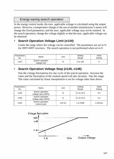
put r will In can
in %
e e.
107
In the energy control mode, the max. applicable voltage is calculated using the outpower. However, a temperature change or the use of another manufacturer’s motochange the fixed parameters, and the max. applicable voltage may not be emitted.the search operation, change the voltage slightly so that the max. applicable voltagebe obtained.
• Search Operation Voltage Limit (n144)Limits the range where the voltage can be controlled. The parameters are set for 200V/400V inverters. The search operation is not performed when set to 0.
• Search Operation Voltage Step (n145, n146)Sets the voltage fluctuations for one cycle of the search operation. Increase thvalue and the fluctuation of the rotation speed will also increase. Sets the rangThe value calculated by linear interpolation is set for voltage other than above.
Energy-saving search operation
Parameters No.
Name UnitSetting Range
Initial Setting
n144Search operation
voltage limit % 0 to 100 0
Parameters No.
Name UnitSetting Range
Initial Setting
n145Search operation
voltage step (100%)% 0.1 to 10.0 0.5
n146Search operation
voltage step (100%)% 0.1 to 10.0 0.2
n143Search operation
control cyclex24 ms 1 to 2000 1 (24ms)
Output voltage

the
108
• Search Operation Power Detection Hold Width (n161)When the power fluctuation is less than this value, the output voltage is held for 3 seconds. Then the search operation mode is activated. Set the hold width in % ofpower which is currently held.
• Power Detection Filter Time Parameter (n162)Response at load change is improved when this value is small. However, at low frequency, unstable rotation will result.
Parameter No.
Name UnitSetting Range
Initial Setting
n161Search operation
voltage limit % 0 to 100 0
Parameter No.
Name UnitSetting Range
Initial Setting
n162Power detection filter
time parameter x 4 ms 0 to 255 5 (20 ms)
Parameter No.
Name UnitSetting Range
Initial Setting
n162Power detection filter
time parameter x 4 ms 0 to 255 5 (20 ms)

t
109
The energy-saving coefficient K2 (n140) is set to a value that corresponds with thamotor code (n158).
Motor Code
Motor Type Voltage Class Capacity Motor Code: n158Energy-saving
coefficient K2: n140
YASKAWAGeneral-purpose Motor
200V
0.1 kW 0 481.70.2 kW 1 356.90.4 kW 2 288.2
0.75 kW 3 223.71.5 kW 4 169.42.2 kW 5 156.83.7 kW 7 122.95.5 kW 9 94.87.5 kW 10 72.7
400V
0.2 kW 21 713.80.4 kW 22 576.4
0.75 kW 23 447.41.5 kW 24 338.82.2 kW 25 313.63.0 kW 26 245.83.7 kW 27 245.85.5 kW 29 189.57.5 kW 30 145.4
YASKAWAInverter Motor
200V
0.1 kW 40 481.70.2 kW 41 356.90.4 kW 42 300.9
0.75 kW 43 224.71.5 kW 44 160.42.2 kW 45 138.93.7 kW 47 106.95.5 kW 49 84.17.5 kW 50 71.7
400V
0.2 kW 61 713.80.4 kW 62 601.8
0.75 kW 63 449.41.5 kW 64 320.82.2 kW 65 277.83.0 kW 66 213.83.7 kW 67 213.85.5 kW 69 168.37.5 kW 70 143.3
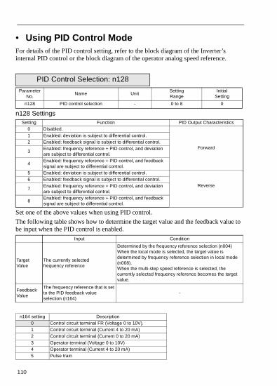
e to
110
• Using PID Control ModeFor details of the PID control setting, refer to the block diagram of the Inverter’s internal PID control or the block diagram of the operator analog speed reference.
n128 Settings
Set one of the above values when using PID control.
The following table shows how to determine the target value and the feedback valube input when the PID control is enabled.
PID Control Selection: n128Parameter
No.Name Unit
Setting Range
Initial Setting
n128 PID control selection - 0 to 8 0
Setting Function PID Output Characteristics0 Disabled.
Forward
1 Enabled: deviation is subject to differential control.2 Enabled: feedback signal is subject to differential control.
3Enabled: frequency reference + PID control, and deviationare subject to differential control.
4Enabled: frequency reference + PID control, and feedback signal are subject to differential control.
5 Enabled: deviation is subject to differential control.
Reverse6 Enabled: feedback signal is subject to differential control.
7Enabled: frequency reference + PID control, and deviationare subject to differential control.
8Enabled: frequency reference + PID control, and feedback signal are subject to differential control.
Input Condition
TargetValue
The currently selected frequency reference
Determined by the frequency reference selection (n004)When the local mode is selected, the target value is determined by frequency reference selection in local mode (n008).When the multi-step speed reference is selected, the currently selected frequency reference becomes the target value.
FeedbackValue
The frequency reference that is set to the PID feedback value selection (n164)
-
n164 setting Description0 Control circuit terminal FR (Voltage 0 to 10V).1 Control circuit terminal (Current 4 to 20 mA)2 Control circuit terminal (Current 0 to 20 mA)3 Operator terminal (Voltage 0 to 10V)4 Operator terminal (Current 4 to 20 mA)5 Pulse train

as
e
r e
a n at ,
=1, l
N2 of
I),
ical
111
Notes: 1. When selecting frequency reference from the control circuit terminal FR the target or feedback value, the V-I switch of SW2 on the control circuit board must be selected depending on the input method (current or voltaginput).
2. Never use the frequency reference from the control circuit terminal FR foboth the target and feedback values. The frequency reference for both thtarget value and the feedback value becomes the same.
(Example)
When the frequency reference from the control circuit terminal FR, with voltage of 0 to 10 V, is selected as the target value and n004=2, and whethe same time the frequency reference from the control circuit terminal FRwith a current of 4 to 20 mA, is selected as the feedback value and n164the feedback value will be set as the frequency reference from the controcircuit terminal FR.
3. When using the analog signal (0 to 10V / 4 to 20mA) which inputs to the Cterminal of the digital operator JVOP-140 as the target or feedback valuePID control, never use it as a multi-analog input. Parameter n077 (multi-function analog input) should be set to 0 (disabled).
• Proportional gain (P), Integral time (I), Differential time (D) (n130, n131, n132)
Adjust the response of the PID control with the proportional gain (P), intregal time (and differential time (D).
Optimize the responsiveness by adjusting it while operating an actual load (mechansystem). Any control (P, I, or D) that is set to zero (0.0, 0.00) will not operate.
Parameter No.
Name UnitSetting Range
Initial Setting
n130 Proportional gain (P) Multiples 0.0 to 25.0 1.0
n131 Intregal Time 1.0s 0.0 to 360.0 1.0
n132 Differential Time (D) 1.0s 0.00 to 2.50 0.00

the
p by too
g e
112
• Intregal (I) Limit (n134)
This parameter prevents the calculated value of the integral control from exceedingfixed amount. There is normally no need to change the setting.
Reduce the setting if there is a risk of load damage, or of the motor going out of stethe inverter’s response when the load suddenly changes. If the setting is reduced much, the target value and the feedback value will not match.
Set this parameter as a percentage of the maximum output frequency with the maximum frequency as 100%.
• PID Offset Adjustment (n133)
Parameter n133 adjusts the PID control offset.
If both the target value and the feedback values are set to zero, adjust the inverteroutput frequency to zero.
• PID Primary Delay Time Parameter (n135)
Parameter n135 is the low-pass filter setting for PID control outputs.
There is normally no need to change the setting.
If the viscous friction of the mechanical system is high or if the rigidity is low causinthe mechanical system to resonate, increase the setting so that it is higher than thresonance frequency period.
Parameter No.
Name UnitSetting Range
Initial Setting
n134 Intregal (I) limit % 0 to 100 100
Parameter No.
Name UnitSetting Range
Initial Setting
n133 PID Offset adjustment % -100 to 10.0 0
Parameter No.
Name UnitSetting Range
Initial Setting
n135 PID primary delay time parameter Seconds 0.0 to 10.0 0.0

113
• PID Output Gain (n163)
This parameter adjusts the output gain.
• PID Feedback Value Adjusting Gain (n129)
Parameter n129 is the gain that adjusts the feedback value.
• PID Feedback Loss Detection (n136, n137, n138)
Parameter No.
Name UnitSetting Range
Initial Setting
n163 PID Output gain Multiples 0.0 to 25.0 1.0
Parameter No.
Name UnitSetting Range
Initial Setting
n129PID feedback value
adjusting gainMultiples 0.0 to 10.0 1.00
Parameter No.
Name UnitSetting Range
Initial Setting
n136Selection of PIDfeedback loss detection
-
0: No detection of PID feedback loss
1: Detection of PIDfeedback loss(Operation continued: FbL alarm)
2: Detection of PID feedback loss(Output shut down: fault)
0
n137PID feedback loss detection level
%0 to 100
100%/Max. output frequency
0
n138PID feedback loss detection time
% 0.0 to 25.5 1.0

114
Int
Inte
gral
Not
e: T
he
inte
gral
can
onl
y be
res
et w
hen
the
inve
rter
is s
topp
ed
or
PID
is c
ance
lled
via
mul
ti-fu
nctio
n in
put.

115

ries,
eters
The
ing
the
ter
he
116
• Using Parameter Copy Function
The VS-606V7 standard digital operator JVOP-140 can store parameters for one inverter. A backup power supply is not necessary since EEPROM is used.
Parameter copy function is possible only for the inverters with the same product sepower supply specifications and control mode (V/f control or vector control).
However, some parameters may not be copied. It is also impossible to copy parambetween VS-606V7 and VSmini J7 inverters.
The prohibition of the reading of parameters from the inverter can be set at n177. parameter data cannot be changed when this parameter is set.
If any alarm occurs during parameter copy, the PRGM will blink and copying will continue.
• Parameter Copy Function Selection (n176)Depending on the setting of n176 for parameter copy function selection, the followfunctions are available:
1. Read all the parameters from the inverter (READ) and store them in EEPROM indigital operator.
2. Copies the parameters stored in the digital operator to the inverter (COPY).
3. Verify that the parameters in the digital operator and the parameters in the inverare the same (VERIFY).
4. Displays the maximum applicable motor capacity and the voltage class of the inverter that has the parameters stored in the digital operator.
5. Displays the software number of the inverter that has the parameters stored in tdigital operator.
Parameter copy function
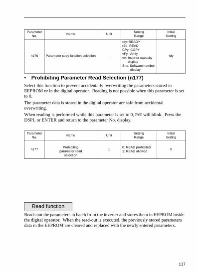
set
e
side ers .
117
• Prohibiting Parameter Read Selection (n177)Select this function to prevent accidentally overwriting the parameters stored in EEPROM or in the digital operator. Reading is not possible when this parameter isto 0.
The parameter data is stored in the digital operator are safe from accidental overwriting.
When reading is performed while this parameter is set to 0, PrE will blink. Press thDSPL or ENTER and return to the parameter No. display.
Reads out the parameters in batch from the inverter and stores them in EEPROM inthe digital operator. When the read-out is executed, the previously stored parametdata in the EEPROM are cleared and replaced with the newly entered parameters
Parameter No.
Name UnitSetting Range
Initial Setting
n176 Parameter copy function selection -
rdy: READYrEd: READCPy: COPYvFy: VerifyvA: Inverter capacity
displaySno: Software number
display
rdy
Parameter No.
Name UnitSetting Range
Initial Setting
n177Prohibiting
parameter readselection
10: READ prohibited1: READ allowed
0
Read function
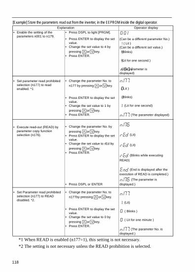
118
[Example] Store the parameters read out from the inverter, in the EEPROM inside the digital operator.
*1 When READ is enabled (n177=1), this setting is not necessary.
*2 The setting is not necessary unless the READ prohibition is selected.
Explanation Operator display• Enable the setting of the
parameters n001 to n179.
• Set parameter read prohibited selection (n177) to read enabled. *1
• Execute read-out (READ) by parameter copy function selection (n176).
• Set Parameter read prohibited selection (n177) to READ disabled. *2.
• Press DSPL to light [PRGM].
• Press ENTER to display the set value.
• Change the set value to 4 by
pressing or key.• Press ENTER.
• Change the parameter No. to
n177 by pressing or key.
• Press ENTER to display the set value.
• Change the set value to 1 by
pressing or key.• Press ENTER.
• Change the parameter No. by
pressing or key.• Press ENTER to display the set
value.• Change the set value to rEd by
pressing or key.• Press ENTER.
• Press DSPL or ENTER
• Change the parameter No. to
n177by pressing or key.
• Press ENTER to display the set value.
• Change the set value to 0 by
pressing or key.• Press ENTER.
(Can be a different parameter No.) ( Lit ) (Can be a different set value.) (Blinks)
(Lit for one second.)
(The parameter is displayed)
( Lit )
(Blinks)
(Lit for one second)
(The parameter displayed)
(Lit)
(Lit)
(Blinks while executing
READ)
(End is displayed after the execution of READ is completed.)
(The parameter is
displayed.)
(Lit)
( Blinks )
( Lit for one minute )
(The parameter No. is displayed.)

is and
ini
), ten.
Writes the parameters stored inside the digital operator in batch to the inverter. Write-in possible only for the inverters with the same product series, power supply specifications control mode (V/f control or vector control). Therefore, writing from 200 V class to 400 V class (or visa versa), from VS-606V7 to VSmJ7 are not possible.Parameter Copy Function Selection (n176), Parameter Read Prohibited Selection (n177Fault history (n178), Inverter Software No. (n179), and hold output frequency are not writ
Following parameters are not written if the inverter capacity is different.
[Example] Write the parameters from EEROM inside the digital operator to the inverter
Copy Function
Parameter No. Name Parameter No. Name
n011 to n017 V/f setting n108 Motor leakage inductance
n036 Motor rated current n109Torque compensation voltage limiter
n080 Carrier frequency n110 Motor no-load current
n105 Torque compensation iron loss n140 Energy-saving coefficient K2
n106 Motor rated slip n158 Motor code
n107 Motor resistance for one phase
Explanation Operator display• Enable the setting of the
parameters n001 to n179.
• Execute write-in (COPY) by Parameter Copy Function Selection (n176).
• Press DSPL to light [PRGM].
• Press ENTER to display the set value.
• Change the set value to 4 by
pressing or key.
• Press ENTER.
• Change the parameter No. to
n176 by pressing or key.• Press ENTER to display the set
value.• Change the set value to CPy by
pressing or key.• Press ENTER.
• Press DSPL or ENTER
(Can be a different parameter No.) ( Lit ) (Can be a different set value.) (Blinks)
(Lit for one second.)
(The parameter No. is displayed)
( Lit )
(Lit)
(Blinks while executing CPY)
(End is displayed after the execution of CPY is completed.)
(The parameter No. is displayed.)
119

ted
120
A setting range check and matching check for the written-in parameters are execuafter the parameters are written from the digital operator to the inverter. If any parameter error is found, the written parameters are discarded and the parametersstored before writing are restored.
When a setting range error is found, the parameter No. where an error occurs is indicated by blinking.
When a matching error is found, ( : a number) is indicated by blinking.

rter,
,
121
Collates the parameters stored in the digital operator with the parameters in the inverter. As well as write-in, VERIFY is possible only for the inverters with same product series, power supply specifications and control mode (V/f control or vectorcontrol).
When the parameters stored in the digital operator correspond to those in the invevFy is displayed by blinking, then End is displayed.
[Example] Collate the parameters stored in EEPROM inside the digital operator
with the parameters in the inverter.
While an unmatched parameter No. is displayed or a parameter value is displayedpressing STOP/RESET interrupts the execution of VERIFY and End is displayed. Pressing DSPL or ENTER returns to the parameter No.
VERIFY function
Explanation Operator display• Enable the setting of the
parameters n001 to n179.
• Execute VERIFY by Parameter Copy Function selection (n176)
• Display the unmatched parameter No.
• Display the parameter value in the inverter.
• Display the parameter value in the digital operator.
• Continue the execution of VERIFY.
• Press DSPL to light [PRGM].
• Press ENTER to display the set value.
• Change the set value to 4 by
pressing or key.• Press ENTER.
• Change the parameter No. to
n176 by pressing or key.• Press ENTER to display the set
value.• Change the set value to vFY by
pressing or key.• Press ENTER.
• Press ENTER.
• Press ENTER.
• Press key.
• Press DSPL or ENTER
(Can be a different parameter No.) ( Lit ) (Can be a different set value.) (Blinks)
(Lit for one second.)
(The parameter is displayed)
(Lit)
(Lit)
(Blinks while executing
VERIFY)
(Blinks) (When n001 is unmatched)
(Blinks)
(Blinks)
(Blinks while executing VERIFY
(End is displayed after the execution of VERIFY is completed.)
(The parameter No. is displayed.)

ed in
The voltage class and maximum applicable motor capacity (whose parameters storthe digital operator are read out) is displayed.[Example] Display the voltage class and maximum applicable motor capacity for the inverter whose parameters stored in EEPROM inside the digital operator.
The following shows the explanation of Inverter Capacity Display
Inverter Capacity Display
Explanation Operator display• Enable the setting of the
parameters n001 to n179.
• Execute Inverter Capacity Display (vA) by parameter copy function selection (n176)
• Press DSPL to light [PRGM].
• Press ENTER to display the set value.
• Change the set value to 4 by
pressing or key.• Press ENTER.
• Change the parameter No. to
n176 by pressing or key.• Press ENTER to display the set
value.
• Change the set value to vA by
pressing or key.• Press ENTER.• Press DSPL or ENTER.
(Can be a different parameter No.) ( Lit ) (Can be a different set value.) (Blinks)
(Lit for one second.)
(The parameter is displayed)
(Lit)
(Lit)
(Lit) (For20P7)*
(The parameter No. is displayed.)
Voltage class
2 Three-phase 200V
b Single-phase 200V
4 Three-phase 400V
Max. applicable motor capacity
200V class 400V class
0.1 0.1kW -
0.2 0.25kW 0.37kW
0.4 0.55kW 0.55kW
0.7 1.1kW 1.1kW
1.5 1.5kW 1.5kW
2.2 2.2kW 2.2kW
3.0 - 3.0kW
4.0 4.0kW 4.0kW
122

re
The software No. (of the inverter whose parameters stored in the digital operator aread out) is displayed.[Example] Display the software No. of the inverter whose parameters stored in EEPROM inside the digital operator.
* Displays Lower 4 digits of the software version.
Software No. Display
Explanation Operator display• Enable the setting of the
parameters n001 to n179.
• Execute Software No. Display (Sno)* by Parameter copy function selection (n176)
• Press DSPL to light [PRGM].• Press ENTER to display the set
value.• Change the set value to 4 by
pressing or key.• Press ENTER.
• Change the parameter No. to
n176 by pressing or key.• Press ENTER to display the set
value.• Change the set value to Sno by
pressing or key.• Press ENTER• Press DSPL or ENTER
(Can be a different parameter No.) ( Lit ) (Can be a different set value.) (Blinks)
(Lit for one second.)
(The parameter is displayed)
(Lit)
(Lit)
(software version: VSP010013)
(The parameter No. is
displayed)
123

124
Display List
Note: While rEd, CPy, or vFy is displayed by blinking, key input on the digital operator is disabled. While rEd, CPy and vFy are not displayed by blinking, pressing DSPL or ENTER redisplays the
parameter No.
Operator display
Description Corrective action
Lit: Setting for parameter copy function selection enabled
-
Lit: READ selectedFlashed: READ under execution
-
Lit: Writing (COPY) selectedBlinks: Writing (COPY) under execution
-
Lit: VERIFY selectedFlashed: VERIFY under execution
-
Lit: Inverter capacity display selected -
Lit: Software No. Display selected -
Lit: READ, COPY (writing), or VERIFY completed
-
Blinks: Attempt to execute READ while Parameter Read Prohibited Selection (n177) is set to 0.
Confirm the necessity to execute READ, then set parameter Read Prohibited selection (n177) to 1 to execute READ.
Blinks: The parameter could not be read properly by READ operation. Or, a main circuit low voltage is detected during READ operation.
Confirm that the main circuit power supply voltage is correct, then re-execute READ.
Blinks: A sumcheck error occurs in the parameter data stored in the digital operator.
The parameter stored in the digital operator cannot be used.Re-execute READ to store the parameters in the digital operator.
Blinks: The password for the connected inverter and that for the parameter data stored in the digital operator do not agree. [EX.]Writing (Copy) from VS-606V7 to Vsmini J7
Check if they are the same product series
Blinks: No parameter data stored in the digital operator.
Execute READ
Blinks: Attempt to execute writing (COPY) or VERIFY between different voltage classes or different control modes
Check each voltage class and control mode.
Blinks: A main circuit low voltage is detected during writing (COPY) operation.
Confirm that the main circuit power supply voltage is correct, then re-execute writing (COPY).
Lit: A sumcheck error occurs in the parameter data stored in the inverter.
Initialize the parameters. If an error occurs again, replace the inverter due to a failure of parameter memory element (EEPROM) in the inverter.
Blinks: Attempt to execute VERIFY between different inverter capacities.
Press ENTER to continue the execution of VERIFY. Press STOP to interupt the execution of VERIFY.
Blinks: A communication error occurs between the inverter and the digital operator.
Check the connection between the inverter and the digital operator.If a communication error occurs during READ operation or writing (COPY) operation, be sure to re-execute READ or COPY.

e of
125
• Unit selection for Frequency Reference Setting/Display
Parameter and monitor display for which selection of unit function is valid
• Function OutlineThe frequency reference, output frequency and the numerical data of frequency reference parameters can be displayed in %, r/min, m/min according to the set valuparameter n035.
• n035 setting
Item Contents
Frequencyreference parameters
Frequency reference 1 to 8 (Parameters n024 to n031)
Jog frequency reference (Parameters n032)
Frequency reference 9 to 16 (parameters n120 to n127)
Monitor display
Frequency reference display (FREF)
Output frequency display (FOUT)
Frequency reference display (U-01)
Output frequency display (U-02)
Parameter No.
Parameter Name DescriptionInitial
Setting
035Unit Selection for frequency Reference Setting / Display
0: in units of 0.01 Hz (less than 100 Hz) 0.1Hz (100 Hz and more)1: in units of r/min (set the number of motor
poles)40 to 3999: in any unit
0
Setting Description
0(Initial value)
• Setting unit: 0.01 Hz (less than 100 Hz), 0.1 Hz (100 Hz and more)• Setting range minFmax (n011) x Frequency reference lower limit (n034) to Fmax (n011) Frequency
reference upper limit (n033), 400 Hz
1
• Setting in units of 0.1% : 100.0 % / Fmax (n011)• Setting range minFrequency reference lower limit (n034) to Frequency reference upper limit (n033),
(400 Hz ÷ Fmax (n011) 100%
2 to 39
• Setting in units of 1 r/min = 120 x Frequency reference (Hz) ÷ n035 (Set the number of motor poles for n035)• Setting range min120 (Fma x (n011) Frequency reference lower limit (n034) ÷ n035~120x
Fmax(n011) x Frequency reference upper limit (n033)) n035, 400Hzx120 P, 9999r/min• Set the display value at 100% of frequency reference (set value of Fmax (n011)) at 1 of
n035.
(Lit)

9,
e
ters
126
Notes:
1. The frequency reference parameters and monitor display data for which this selection of unit function is valid, are stored in the inverter in units of Hz.
The units are converted as follows.
2. The upper limit for each unit is the figure whose fractions below the significant digits are cut off.
(Example) Where the upper limit value for the unit Hz is 60.00 Hz and n035 = 3
120 x 60.00 Hz ÷ 39 = 184.9, accordingly 184 r/min is displayed for thupper limit value.
For the displays other than upper limit value, the fractions below the significantdigits are rounded.
3. To execute VERIFY for parameter COPY function, frequency reference parame(in units of Hz) is applied.
Parameter n035
SettingDescription
40 to
3999
• Set the display value at 100% of frequency reference (set value of Fmax(n011)) at 1st to 4th digit of n035. By a number of 4th digit of n035, set the position of decimal point. By 1st to 4th digit of n035, set a 3-digit figure excluding decimal point. Number of 4th digit. Position of decimal point 40 to 3999
0 1 2 3 0. (Example) To display 20.0 at 100% of frequency reference, set n035 to “1200.”• Setting range min(Lower 3-digits of n035) x Frequency reference lower limit (n034) to (Lower 3-digits
of n035) x Frequency reference upper limit (n033), 400Hz (Lower 3-digits of n035) to Fmax(n011), 999
Max. upper limit value: (Set value ÷ (Lower 3-digits of n035)) x Fmax(n011)< 400Hz
Setting/Display parameter n035 Frequency reference parameters
Data for monitor display
Display
Setting
systemEach unit Units of Hz

nts
127
7. Maintenance and Inspection• Periodical InspectionPeriodically inspect the inverter as described in the following table to prevent accideand to ensure high performance with high-reliability.
• Part ReplacementInverter’s maintenance periods are noted below. Keep them as reference.
Part Replacement Guidelines
Note: Usage conditions are as follows:• Ambient temperature: Yearly average of 30°C.• Load factor: 80% max.• Operating rate: 12 hours max. per day.
Location to Check Check For SolutionTerminal, unit mounting screws, etc.
Connection hardware is properly seated and securely tightened.
Properly seat and tighten hardware.
Cooling fins Built up dust, dirt, and debris
Blow with dry compressed air:
39.2 X 10⁴ to 58.8 X 10⁴ Pa, 57 to 85 psi (4
to 6kg / cm2) pressure.
Printed circuit boardAccumulation of conductive material or oil mist
Blow with dry compressed air:
39.2 X 10⁴ to 58.8 X 10⁴ Pa, 57 to 85 psi (4
to 6kg / cm2) pressure. If dust or oil cannot be removed, replace the inverter unit.
Power elements and smoothing capacitor
Abnormal odor or discoloration Replace the inverter unit.
Cooling fan Abnormal noise or vibration. Cumulative operation time exceeding 20,000 hours.
Replace the cooling fan.
Part Standard Replacement Period Replacement MethodCooling fan 2 to 3 years Replace with new part.
Smoothing capacitor 5 yearsReplace with new part.
(Determine need by inspection).Breaker relays — Determine need by inspection.
Fuses 10 years Replace with new part.Aluminum capacitors on
PCBs5 years
Replace with new board. (Determine need by inspection).

128
Replacement of cooling fan• Inverter of W-dimension (width) 2.68 inches (68mm), 5.51 inches (140mm), 6.69 inches (170mm), and 7.09 inches (180mm).
1. Removal(1) Press the right and left clicks of the fan
cover to direction 1, and then pull them to direction 2 to remove the fan cover from the inverter unit.
(2) Pull the wiring to direction 3 from the fan cover rear face, and remove the protective tube and connector.
(3) Open the left and right sides of the fan cover to remove the cooling fan from cover.
2. Mounting(1) Mount the cooling fan on the fan cover.
The arrow mark to indicate the wind direction of the cooling fan must be in the opposite side to the cover.
(2) Connect the connector and mount the pro-tective tube firmly. Mount the connector joint section on the fan cover rear face.
(3) Mount the fan cover on the inverter. Be sure to mount the right and left clicks of the fan cover on the heatsink.
(4)

s
e).
r to
129
8. Fault Diagnosis and Corrective ActionsThis section describes the alarm and fault displays, explanations for fault conditionand corrective actions to be taken if the VS-606V7 malfunctions.
< Corrective Actions for models with blank cover >1. Input fault reset or cycle the power supply OFF and ON.
2. When a fault cannot be corrected:
(1) Turn the power supply OFF and check the wiring and external circuit (sequenc
(2) Turn the power supply OFF and replace the blank cover with the digital operatodisplay faults. The faults are displayed after turning the power ON.

130
< Corrective Actions of models with digital operator >
Alarm Display and ContentsAlarm Display
Inverter Status
ExplanationCauses and
Corrective ActionsDigital Operator
RUN (Green)ALARM (Red)
Blinking
Warning
Fault contacts do not change state.
UV (Main circuit low voltage)Main circuit DC voltage drops below the low-voltage detection level while the inverter output is OFF. 200V: Stops at main circuit
DC voltage below approx. 200V (160V for single phase)
400V:Stops at main circuit DC voltage below approx. 400V.
(Control supply fault) Control power supply fault is detected while the inverter output is OFF.
Check the following:• Power supply
voltage• Main circuit power
supply wiring is connected.
• Terminal screws are securely tightened.
Blinking
OV (Main circuit over voltage)Main circuit DC voltage exceeds the over voltage detection level while the inverter output is OFF.Detection level:200V class: Approx 410V or more400V class: Approx 820V or more
Check the power supply voltage.
Blinking
OH (Cooling fin overheat)Intake air temperature rises while the inverter output is OFF.
Check the intake air temperature.
Blinking
OH3(Inverter overheating pre-alarm)* signal is input.
Release the input of inverter overheating pre-alarm signal.
Blinking
CAL (MEMOBUS communications waiting)Correct data has not been received from the PLC when the parameters n003 (operation command selection) is 2 or n004 (frequency reference selection) is 6, and power is turned ON.
Check communication devices and transmission signals.
: ON : Blinking : OFF
*Display only applies to 200/400V class. 7.5/10hp(5.5/7.5kW) inverters.

131
Blinking
Warning
Fault contacts do not change state.
OP(parameter setting error when the parameter setting is performed through the MEMOBUS communications)OP1: Two or more values are
set for multi-function input selection. (parameters n050 to n056)
OP2: Relationship among V / f parameters is not correct. (parameters n011, n013, n014, n016)
OP3: Setting value of motor rated current exceeds 150% of inverter rated current. (parameter n036)
OP4: Upper/lower limit of frequency reference is reversed. (parameters n033, n034)
OP5: (parameters n083 to n085)
Check the setting values.
Blinking
OL 3 (Over torque detection)Motor current exceeded the preset value in parameter n098.
Reduce the load and expand the accel/decel time.
Blinking
SER (Sequence error)Inverter receives LOCAL/REMOTE select command or communication/control circuit terminal changing signals from the multi-function terminal while the inverter is outputting.
Check the external circuit (sequence).
Alarm DisplayInverter Status
ExplanationCauses and
Corrective ActionsDigital Operator
RUN (Green)ALARM (Red)

132
Blinking
Warning
Fault contacts do not change state.
BB (External baseblock)Baseblock command at multi-function terminal is active. The inverter output is shut OFF (motor coasting). Temporary condition is cleared when input command is removed.
Check the external circuit (sequence).
Blinking
EF (Simultaneous FWD/REV run commands)When FWD and REV run commands are simultaneously input for over 500ms, the inverter stops according to parameter n005.
Check the external circuit (sequence).
Blinking
STP (Operator function stop) STOP RESET is pressed during running by the control circuit terminals FWD/REV command, or by the run command from communications. The inverter stops according to parameter n005.STP (Emergency stop) Inverter receives emergency stop alarm signal. Inverter stops according to parameter n005.
Open FWD/REV command of control circuit terminals.
Check the external circuit (sequence).
Blinking
FAN (Cooling fan fault)Cooling fan is locked.
Check the following:• Cooling fan• Cooling fan wiring is
not connected.
Blinking
CE (MEMOBUS) communications fault
Check the communication devices or communication signals.
FBL (PID feedback loss detection)PID feedback value drops below the detection level. When PID feedback loss is detected, the inverter operates according to the n136 setting.
Check the mechanical system and correct the cause, or increase the value of n137.
Blinking
Option card communications fault.Communication fault has occurred in a mode that run command and frequency reference are set from the communication option card.
Check the communication devices or communication signals.
Alarm DisplayInverter Status
ExplanationCauses and
Corrective ActionsDigital Operator
RUN (Green)ALARM (Red)
Blinking

Protective Operation
Output is shut OFF and motor coasts to a stop.
OC (Over current)Inverter output current momentarily exceeds approx. 250% of rated current.
• Short circuit or grounding at inverter output side.
• Excessive load WK2
• Extremely rapid accel/decel time (parameters n019 to n022)
• Special motor used• Starting motor during
coasting• Motor of a capacity
greater than the inverter rating has been started.
• Magnetic contactor open/closed at the inverter output side.
(Load Short-circuit)*The Inverter output or load was short circuited.
A short-circuit or ground fault.
⇓Reset the fault correcting its cause.
(Ground Fault)*The ground fault current at the Inverter output exceeded approximately 50% of the Inverter rated output current.
A ground fault occurred at the Inverter output.
⇓Reset the fault after correcting its cause.
OV (Main circuit over voltage)Main circuit DC voltage exceeds the overfatigue detection level because of excessive regenerative energy from the motor.Detection level:200V: Stops at main circuit
DC voltage below approx. 410V
400V: Stops at main circuitDC voltage approx. 820V or more
• Insufficient decel time (parameters n020 and n022)
• Lowering of minus load (elevator, etc.)
⇓• Increase decel time.• Connect optional
braking resistor.
UV1 (Main circuit low voltage)Main circuit DC voltage drops below the low voltage detection level while the inverter output is ON.200V: Stops at main circuit
DC voltage below approx. 200V (160V for single phase)
400V: Stops at main circuitDC voltage approx. 400V or more
• Reduction of input power supply voltage
• Open phase of input supply
• Occurrence of momentary power loss
⇓Check the following:• Power supply
voltage• Main circuit power
supply wiring is connected.
• Terminal screws are securely tightened.
Alarm DisplayInverter Status
ExplanationCauses and
Corrective ActionsDigital Operator
RUN (Green)ALARM (Red)
* Display only applies to 200/400V class,7.5/10Hp, 5.5/7.5 kW inverters.
133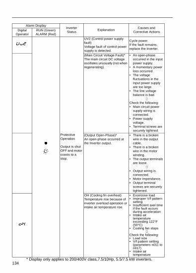
134
Protective Operation
Output is shut OFF and motor coasts to a stop.
UV2 (Control power supply fault)Voltage fault of control power supply is detected.
Cycle power.If the fault remains, replace the inverter.
(Main Circuit Voltage Fault)*The main circuit DC voltage oscillates unusually (not when regenerating).
• An open-phase occurred in the input power supply.
• A momentary power loss occurred.
• The voltage fluctuations in the input power supply are too large.
• The line voltage balance is bad.
⇓Check the following:• Main circuit power
supply wiring is connected.
• Power supply voltage.
• Terminal screws are securely tightned.
(Output Open-Phase)*An open-phase occurred at the Inverter output.
• There is a broken wire in the output cable.
• There is a broken wire in the motor winding.
• The output terminals are loose.
⇓• Output wiring is
connected.• Motor impendance.• Output terminal
screws are securely tightened.
OH (Cooling fin overheat)Temperature rise because of inverter overload operation or intake air temperature rise.
• Excessive load• Improper V/f pattern
setting• Insufficient axel time
if the fault occurs during acceleration
• Intake air temperature exceeding 122°F (50°C)
• Cooling fan stops⇓
Check the following:• Load size• V/f pattern setting
(parameters n011 to n017)
• Intake air temperature
Alarm DisplayInverter Status
ExplanationCauses and
Corrective ActionsDigital Operator
RUN (Green)ALARM (Red)
* Display only applies to 200/400V class,7.5/10Hp, 5.5/7.5 kW inverters.

135
Protective Operation
Output is shut OFF and motor coasts to a stop.
RH (Installed type braking resistor overheating)
The protection function has operated.
• The declaration time is too short.
• The regenerative energy from the motor is too large.
⇓• Increase the
deceleration time.• Reduce the
regenerative load.
(Internal Braking Transistor Fault)The braking transistor is not operating properly.
• Replace the Inverter
OL1 (Motor overload)Motor overload protection operates by built-in electronic thermal overload relay.
• Check the load size or V/f pattern setting (parameters n011 to n017)
• Set the motor rated current shown on the nameplate by parameter n036.
OL2 (Inverter overload)Inverter overload protection operates by built-in electronic thermal overload relay.
• Check the load size or V/f pattern setting (parameters n011 to n017)
• Check the inverter capacity
OL3 (Over torque detection)V/f mode: Inverter output
current exceeded the preset value in parameter n098.
Vector mode: Motor current or torque exceeded the preset value in parameters n097 and n098.
When over torque is detected, inverter performs operation according to the preset setting of parameter n096.
Check the driven machine and correct the cause of the fault, or increase the value of parameter n098 up to the highest value allowed for the machine.
Alarm DisplayInverter Status
ExplanationCauses and
Corrective ActionsDigital Operator
RUN (Green)ALARM (Red)
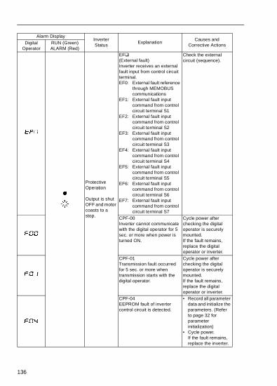
136
Protective Operation
Output is shut OFF and motor coasts to a stop.
EF (External fault)Inverter receives an external fault input from control circuit terminal.EF0: External fault reference
through MEMOBUS communications
EF1: External fault input command from control circuit terminal S1
EF2: External fault input command from control circuit terminal S2
EF3: External fault input command from control circuit terminal S3
EF4: External fault input command from control circuit terminal S4
EF5: External fault input command from control circuit terminal S5
EF6: External fault input command from control circuit terminal S6
EF7: External fault input command from control circuit terminal S7
Check the external circuit (sequence).
CPF-00Inverter cannot communicate with the digital operator for 5 sec. or more when power is turned ON.
Cycle power after checking the digital operator is securely mounted.If the fault remains, replace the digital operator or inverter.
CPF-01Transmission fault occurred for 5 sec. or more when transmission starts with the digital operator.
Cycle power after checking the digital operator is securely mounted.If the fault remains, replace the digital operator or inverter.
CPF-04EEPROM fault of inverter control circuit is detected.
• Record all parameter data and initialize the parameters. (Refer to page 32 for parameter initialization)
• Cycle power.If the fault remains, replace the inverter.
Alarm DisplayInverter Status
ExplanationCauses and
Corrective ActionsDigital Operator
RUN (Green)ALARM (Red)

137
Protective Operation
Output is shut OFF and motor coasts to a stop.
CPF-05AD converter fault is detected
Cycle power.If the fault remains replace the inverter.
CPF-06• Option card connecting
fault• A non-corresponding option
card is connected.
Remove power to the inverter.Check the connection of the digital operator.Verify inverter software number (n179).
CPF-07Operator control circuit (EEPROM or AD converter) fault
Cycle power after checking the digital operator is securely mounted.If the fault remains, replace the digital operator or inverter.
Communication option card self diagnostic error
Option card fault
Replace the option card.Communication option card
model code error
Communication option card DPRAM error
OPR (Operator connecting fault)
Cycle power.If the fault remains, replace the inverter.
CE (MEMOBUS communications fault)
Check the communication devices or communication signals.
Alarm DisplayInverter Status
ExplanationCauses and
Corrective ActionsDigital Operator
RUN (Green)ALARM (Red)
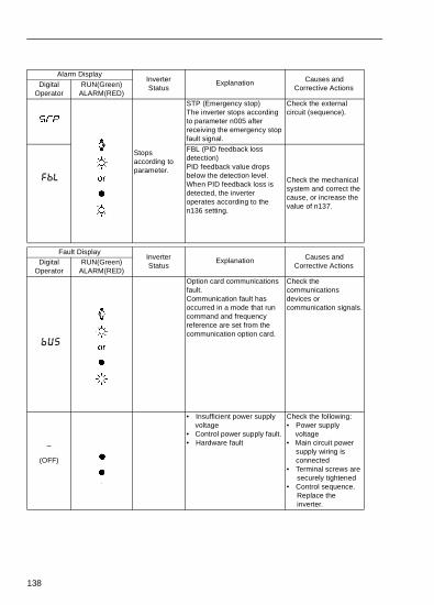
138
Alarm DisplayInverter Status
Explanation Causes and Corrective ActionsDigital
OperatorRUN(Green)
ALARM(RED)
Stops according to parameter.
STP (Emergency stop)The inverter stops according to parameter n005 after receiving the emergency stop fault signal.
Check the external circuit (sequence).
FBL (PID feedback loss detection)PID feedback value drops below the detection level.When PID feedback loss is detected, the inverter operates according to the n136 setting.
Check the mechanical system and correct the cause, or increase the value of n137.
Fault DisplayInverter Status
Explanation Causes and Corrective ActionsDigital
OperatorRUN(Green)
ALARM(RED)Option card communications fault.Communication fault has occurred in a mode that run command and frequency reference are set from the communication option card.
Check the communications devices or communication signals.
_
(OFF)
• Insufficient power supply voltage
• Control power supply fault.• Hardware fault
Check the following:• Power supply
voltage• Main circuit power
supply wiring is connected
• Terminal screws are securely tightened
• Control sequence. Replace the inverter.

139
9. Specifications• Standard Specifications (200V Class)
Voltage Class 200V single- / 3-phase
ModelCIMR-V7*C
3-phase 20P1 20P2 20P4 20P7 21P5 22P2 23P7 25P5 27P5Single-phase B0P1 B0P2 B0P4 B0P7 B1P5 B2P2 B3P7 - -
Max. Applicable Motor Output kW* 0.1 0.25 0.55 1.1 1.5 2.2 3.7 5.5 7.5
Out
put
Ch
arac
teris
tics Inverter Capacity (kVA) 0.3 0.6 1.1 1.9 3.0 4.2 6.7 9.5 13
Rated Output Current (A) 0.8 1.6 3 5 8 11 17.5 25 33
Max. Output Voltage (V)3-phase, 200 to 230V (proportional to input voltage)Single-phase, 200 to 240V (proportional to input voltage)
Max. Output Frequency (Hz) 400 Hz (Programmable)
Input Current (A)
(3-Phase) 1.1 1.9 3.9 6.4 11.0 15.1 24.0 33.0 39.6(Single-Phase) 1.8 3.7 7.4 12.8 20.5 24.0 40.0 - -
Pow
erS
uppl
y
Rated Input Voltage and Frequency
3-phase, 200 to 230V, 50/60HzSingle-phase, 200 to 240V, 50/60Hz
Allowable Voltage Fluctuation -15 to +10%Allowable Frequency Fluctuation ±5%
Co
ntro
l Cha
ract
eris
tics
Control Method Sine wave PWM (V/f control/voltage control selectable)Frequency Control Range 0.1 to 400Hz
Frequency Accuracy (Temperature Change)
Digital reference: ±0.01% (-10 to +50°C)Analog reference: ±0.5% (25±10°C)
Frequency Setting ResolutionDigital reference: 0.01Hz (less than 100Hz) / 0.1Hz (100Hz or more)Analog reference: 1 / 1000 of max. output frequency
Output Frequency Resolution 0.01HzOverload Capacity 150% rated output current for one minute
Frequency Reference Signal0 to 10VDC (20kΩ), 4 to 20mA (250Ω), 0 to 20mA (250Ω) pulse train input, frequency setting potentiometer (Selectable)
Accel/Decel Time0.00 to 6000 sec. (accel/decel time are independently programmed)
Braking Torque
Short-term average deceleration torque‡0.1, 0.25kW (0.13HP, 0.25HP): 150%0.55, 1.1kW (0.5 HP, 1HP): 100%1.5kW (2HP): 50%2.2kW(3HP) or more: 20%Continuous regenerative torque: Approx. 20% (150% with optional braking resistor, braking transistor built-in)
V/f Characteristics Possible to program any V/f pattern
* Based on a standard 4-pole motor for max. applicable motor output.‡ Shows deceleration torque for uncoupled motor decelerating from 60Hz
with the shortest possible deceleration time.

140
Pro
tect
ive
Fun
ctio
ns
Motor Overload Protection Electronic thermal overload relay
Instantaneous OvercurrentMotor coasts to a stop at approx. 250% of inverter rated current
OverloadMotor coasts to a stop after 1 minute at 150% of inverter rated output current
Overvoltage Motor coasts to a stop if DC bus voltage exceed 410V
UndervoltageStops when DC bus voltage is approx. 200V or less (approx. 160V or less for single-phase series)
Momentary Power Loss
Following items are selectable: Not provided (stops if power loss is 15ms or longer), continuous operation if power loss is approx. 0.5s or shorter, continuous operation
Cooling Fin Overheat Protected by electronic circuit
Stall Prevention LevelCan be set individual level during accel/decel, provided/not provided available during coast to a stop
Cooling Fan Fault Protected by electronic circuit (fan lock detection)Ground Fault Protected by electronic circuit (overcurrent level)
Power Charge IndicationON until the DC bus voltage becomes 50V or less. RUN lamp stays ON or digital operator LED stays ON.
Oth
er F
unct
ions
Inpu
t Sig
nals
Multi-function Input
Seven of the following input signals are selectable: Forward/reverse run (3-wire sequence), fault reset, external fault (NO/NC contact input), multi-step speed operation, Jog command, accel/decel time select, external baseblock (NO/NC contact input), speed search command, accel/decel hold command, LOCAL/REMOTE selection, communication/control circuit terminal selection, emergency stop fault emergency stop alarm UP/DOWN command, self test, PID control cancel, PID integral reset/hold
Out
put
Sig
nals
Multi-function Output
Following output signals are selectable (1 NO/NC contact output, 2 photo-coupler outputs): Fault, running, zero speed, at frequency, frequency detection (output frequency ≤ or ≥ set value), during over torque detection, during undervoltage detection, minor error, during baseblock, operation mode, inverter run ready, during fault retry, during UV, during speed search, data output through communication, PID feedback loss detection
Standard Functions
Voltage vector control, full-range automatic torque boost, slip compensation, DC injection braking current/time at start/stop frequency reference bias/gain, MEMOBUS communications (RS-485/422, max. 19.2K bps), PID control, energy-saving control, parameter copy, frequency reference with built-in potentiometerUnit selection for frequency reference setting/display
Voltage Class 200V single- / 3-phase
ModelCIMR-V7*C
3-phase 20P1 20P2 20P4 20P7 21P5 22P2 23P7 25P5 27P5Single-phase B0P1 B0P2 B0P4 B0P7 B1P5 B2P2 B3P7 - -

141
Oth
er F
unc
tions
Dis
play Status Indicator LED RUN and ALARM provided as standard LEDs
Digital Operator (JVOP-140)
Available to monitor frequency reference, output frequency, output current
TerminalsMain circuit: screw terminalsControl circuit: plug-in screw terminal
Wiring Distance between Inverter and Motor
328ft (100m) or less#
EnclosureOpen chassis IP20, Open chassis IP20 (Top-closed type), or enclosed wall-mounted NEMA 1
Cooling Method
Cooling fan is provided for the following models:200V, 0.75kW or larger inverters (3-phase)200V, 1.5kW or larger inverters (single-phase)Others models are self-cooling
Env
iron
men
tal
Con
ditio
ns
Ambient Temperature
Open chassis IP20 : 14 to 122°F (-10 to +50°C)Open chassis IP20 (Top-closed type) and enclosedwall mounted NEMI1. : 14 to 105°F (-10 to +40°C) (not frozen)
Humidity 95% RH or less (non-condensing)Storage Temperature -4 to 140°F (-20 to +60°C)
Location Indoor (free from corrosive gases or dust)Elevation 3280ft (1000m) or less
Vibration Up to 9.8m / S2 (1G) at less than 20Hz, up to 2m / S2 (0.2G) at less than 20 to 50Hz
* Temperature during shipping (for short period)# For details, refer to “Reducing motor noise or leakage current (n080)” on
page 68.
Voltage Class 200V single- / 3-phase
ModelCIMR-V7*C
3-phase 20P1 20P2 20P4 20P7 21P5 22P2 23P7 25P5 27P5Single-phase B0P1 B0P2 B0P4 B0P7 B1P5 B2P2 B3P7 - -

142
• Standard Specifications (400V Class)
Voltage Class 400V 3-phase
ModelCIMR-V7*C
3-phase 40P2 40P4 40P7 41P5 42P2 43P0 43P7 45P5 47P5Single-phase – – – – – – – – –
Max. Applicable Motor Output HP (kW)*
0.5(0.2)
0.75(0.4)
2(0.75)
3(1.5)
3(2.2)
3(3.0)
5(3.7)
7.5(5.5)
10(7.5)
Out
put
Cha
ract
eris
tics Inverter Capacity (kVA) 0.9 1.4 2.6 3.7 4.2 5.5 7.0 11 14
Rated Output Current (A) 1.2 1.8 3.4 4.8 5.5 7.2 9.2 14.8 18Max. Output Voltage (V) 3-phase, 380 to 460V (proportional to input voltage)
Max. Output Frequency (Hz)
400 Hz (Programmable)
Input Current (A)
(3-Phase) 1.6 2.4 4.7 7.0 8.1 10.6 12.0 19.6 23.8
Pow
er
Sup
ply
Rated Input Voltageand Frequency
3-phase, 380 to 460V, 50/60Hz
Allowable Voltage Fluctuation
-15 to +10%
Allowable Frequency Fluctuation
±5%
Con
trol
Cha
ract
eris
tics
Control Method Sine wave PWM (V/f control/voltage control selectable)Frequency Control Range 0.1 to 400Hz
Frequency Accuracy (Temperature Change)
Digital reference: ±0.01%, 14 to 122°F (-10 to +50°C)Analog reference: ±0.5%, 59 to 95°F (25 ±10°C)
Frequency Setting ResolutionDigital reference: 0.01Hz (less than 100Hz) / 0.1Hz (100Hz or more)Analog reference: 1 / 1000 of max. output frequency
Output Frequency Resolution
0.01Hz
Overload Capacity 150% rated output current for one minute
Frequency Reference Signal
0 to 10VDC (20kΩ), 4 to 20mA (250Ω), 0 to 20mA (250Ω) pulse train input, frequency setting potentiometer (Selectable)
Accel/Decel Time0.00 to 6000 sec. (accel/decel time are independently programmed)
Braking Torque
Short-term average deceleration torque‡0.2kW: 150%0.75kW: 100%2HP (1.5kW): 50%3HP (2.2kW) or more: 20%Continuous regenerative torque: Approx. 20% (150% with optional braking resistor, braking transistor built-in)
V/f Characteristics Possible to program any V / f pattern
* Based on a standard 4-pole motor for max. applicable motor output.‡ Shows deceleration torque for uncoupled motor decelerating from 60Hz
with the shortest possible deceleration time.

143
Pro
tect
ive
Fun
ctio
ns
Motor Overload Protection Electronic thermal overload relay
Instantaneous Over CurrentMotor coasts to a stop at approx. 250% of inverter rated current
OverloadMotor coasts to a stop after 1 minute at 150% of inverter rated output current
Over Voltage Motor coasts to a stop if DC bus voltage exceed 820VUnder Voltage Stops when DC bus voltage is approx. 400V or less
Momentary Power LossFollowing items are selectable: Not provided (stops if power loss is 15ms or longer), continuous operation if power loss is approx. 0.5s or shorter, continuous operation
Cooling Fin Overheat Protected by electronic circuit
Stall Prevention LevelCan be set to individual levels during accel/decel, provided/not provided available during coast to a stop
Cooling Fan Fault Protected by electronic circuit (fan lock detection)Ground Fault Protected by electronic circuit (over current level)
Power Charge Indication ON until the DC bus voltage becomes 50V or less.
Other Functions
Inpu
t Sig
nals
Multi-function Input
Seven of the following input signals are selectable: Forward/reverse run (3-wire sequence), fault reset, external fault (NO/NC contact input), multi-step speed operation, Jog command, accel/decel time select, external baseblock (NO/NC contact input), speed search command, accel/decel hold command, LOCAL/REMOTE selection, communication/control circuit terminal selection, emergency stop fault emergency stop alarm, UP/DOWN command, self-test, PID control cancel, PID intregal reset/hold
Out
put
Sig
nals
Multi-function Output
Following output signals are selectable (1 NO/NC contact output, 2 photo-coupler outputs): Fault, running, zero speed, at frequency, frequency detection (output frequency ≤ or ≥ set value), during over torque detection, during under voltage detection, minor error, during baseblock, operation mode, inverter run ready, during fault retry, during UV, during speed search, data output through communication, PID feedback loss detection
Standard Functions
Voltage vector control, full-range automatic torque boost, slip compensation, DC injection braking current/time at start/stop frequency reference bias/gain, MEMOBUS communications (RS-485/422, max. 19.2K bps), PID control, energy-saving control, parameter copy, frequency reference with built-in potentiometer, Unit selection for frequency reference setting/display
* The protection functions at approximately 50% of inverter rated output current.
Voltage Class 400V 3-phase
ModelCIMR-V7*C
3-phase 40P2 40P4 40P7 41P5 42P2 43P0 43P7 45P5 47P5Single-phase – – – – – – – – –

144
Oth
er F
unc
tions
Dis
play Status Indicator LED RUN and ALARM provided as standard LEDs
Digital Operator (JVOP-140)
Available to monitor frequency reference, output frequency, output current
TerminalsMain circuit: screw terminalsControl circuit: plug-in screw terminal
Wiring Distance between Inverter and Motor
328ft (100m) or less#
EnclosureOpen chassis IP20, Open chassis IP20 (Top-closed type), or enclosed wall-mounted NEMA 1
Cooling MethodCooling fan is provided for the following models: 400V, 1.5kW or larger inverters (3-Phase)Others models are self-cooling
Env
iron
men
tal
Con
ditio
ns
Ambient Temperature
Open chassis IP20 : -10 to +50°C (14 to 122°F)Open chassis IP20 (Top-closed type) and enclosedwall mounted NEMA1. : -10 to +40°C (14 to 105°F) (not frozen)
Humidity 95% RH or less (non-condensing)Storage Temperature* -4 to 140°F (-20 to +60°C)
Location Indoor (free from corrosive gases or dust)Elevation 3280ft (1000m) or less
Vibration Up to 9.8m / S2 (1G) at less than 20Hz, up to 2m / S2 (0.2G) at less than 20 to 50Hz
* Temperature during shipping (for short period)# For details, refer to “Reducing motor noise or leakage current (n080)” on
page 68.
Voltage Class 400V 3-phase
ModelCIMR-V7*C
3-phase 40P2 40P4 40P7 41P5 42P2 43P0 43P7 45P5 47P5Single-phase – – – – – – – – –

145
• Standard Wiring
FOR SINGLE-PHASEUSE R\LI AND S\L2
(MAX. 33kHz)
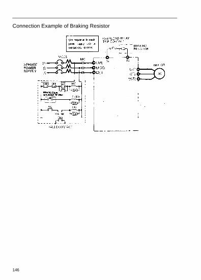
146
Connection Example of Braking Resistor

147
Terminal Description
* DC power supply input terminal is not applied to CE/UL standards.‡ Can be switched to pulse monitor output.
Type Terminal Name Function (Signal Level)M
ain
Circ
uit
R/L1,S/L2,T/L3
AC power supply inputAlways use terminal R/L1, S/L2 for single-phase inverters.Never connect to terminal T/L3.
U/T1,V/T2,W/T3
Inverter output Inverter output
B1, B2 Braking resistor connection Braking resistor connection
+2, +1 DC reactor connectionWhen connecting optional DC reactor, remove the main circuit short-circuit bar between +2 and +1.
+1, (–) DC power supply input DC power supply input (+1: positive –: negative)*
GroundingGrounding 200V: ground to local grounding codes
400V: ground to local grounding codes
Con
tro
l Circ
uit
Inpu
t
Seq
uenc
e
S1 Multi-function input selection 1Factory setting closed: FWD run, open: REV run
Photo-coupler insulation 24VDC, 8mA.
S2 Multi-function input selection 2Factory setting closed: REV run, open: FWD run
S3 Multi-function input selection 3Factory setting: External fault (NO contact)
S4 Multi-function input selection 4 Factory setting: Fault reset
S5 Multi-function input selection 5Factory setting: Multi-step speed reference 1
S6 Multi-function input selection 6Factory setting: Multi-step speed reference 2
S7 Multi-function input selection 7 Factory setting: Jog referenceSC Multi-function input selection common For control signal
Fre
quen
cy r
efer
ence RP Master speed reference pulse
train input 33kHz max.
FS Power for frequency setting +12V (permissible current 20mA max.)
FR Master speed frequency reference 0 to +10VDC (20kΩ) or 4 to 20mA (250kΩ) or 0 to 20mA (250Ω) (1/1000 resolution)
FCFrequency reference common
0V
Out
put
Mul
ti-fu
nctio
n co
ntac
t out
put MA NO contact output
Factory setting: faultContact capability 250VAC 1A or less, 30VDC 1A or less
MB NC contact outputMC Contact output commonP1 Photo-coupler output 1 Factory setting: Run
Photo-coupler output +48VDC, 50mA or less
P2 Photo-coupler output 2Factory setting: Frequency agreed
PCPhoto-coupler output common ‡
0V
AM Analog monitor outputFactory setting:Output frequency 0 to +10V +10VDC, 2mA or less,
8-bit resolutionAC Analog monitor common 0V
Com
mun
icat
ion
Circ
uit
Term
inal
ME
MO
BU
Sco
mm
uni
catio
ns R+ Communications input (+)MEMOBUS communicationRun through RS-485 orRS-422.
RS-485/422MEMOBUS protocol, 19.2 kps max.
R- Communications input (-)S+ Communications output (+)S- Communications output (-)

148
• Sequence input connection with NPN/PNP transistor
Sequence connection with NPN transistor (0V common)
When connecting sequence inputs (S1 to S7)with transistor, turn the rotary switch SW1depending on the polarity (0V common: NPNside, +24V common: PNP side). Factory setting: NPN side

149
Sequence connection with PNP transistor (+24V common)

150
• Dimensions
Fig. 2
D1

151
Dimensions in inches (mm)/mass in lb (kg) /Heat Loss (W)
Voltage class
Capacity HP(kW)
W H D W1 H1 H2 H3 H4 D1 d MassHeat Loss (W)
Fig.Heat-sink
Unit Total
200V3-
phase
0.13 (0.1)
2.68 (68)
5.83 (148)
2.99 (76)
2.20 (56)
4.65 (118)
0.20 (5)
5.04 (128)
0.79(20)
M41.55 (0.7)
3.7 9.3 13.0 1
0.25 (0.2)
2.68 (68)
5.83 (148)
2.99 (76)
2.20 (56)
4.65 (118)
0.20 (5)
5.04 (128)
0.79(20)
M41.55 (0.7)
7.7 10.3 18.0 1
0.5(0.4)
2.68 (68)
5.83 (148)
4.25 (108)
2.20 (56)
4.65 (118)
0.20 (5)
5.04 (128)
0.79(20)
M42.20 (1.0)
15.8 12.3 28.1 1
1 (0.75)
2.68 (68)
5.83 (148)
5.04 (128)
2.20 (56)
4.65 (118)
0.20 (5)
5.04 (128)
0.79(20)
M42.65 (1.2)
28.4 16.7 45.1 1
2 (1.5)
4.25 (108)
5.83 (148)
5.16 (131)
3.78 (96)
4.65 (118)
0.20 (5)
5.04 (128)
0.79(20)
M43.53 (1.6)
53.7 19.1 72.8 2
3 (2.2)
4.25(108)
5.83 (148)
5.51(140)
3.78(96)
4.65(118)
0.20 (5)
5.04 (128)
0.79(20)
M43.75(1.7)
60.4 34.4 94.8 2
5 (3.7)
5.51(140)
5.83(148)
5.63(143)
5.04(128)
4.65(118)
0.20 (5)
5.04 (128)
0.79(20)
M45.30(2.4)
96.7 52.4 149.1 2
7.5(5.5)
7.09(180)
10.24(260)
6.70(170)
6.46(164)
9.61(244)
0.31(8)
2.56(65)
M510.14(4.6)
168.8 87.7 256.5 2
10(7.5)
7.09(180)
10.24(260)
6.70(170)
6.46(164)
9.61(244)
0.31(8)
2.56(65)
M510.58(4.8)
209.6 99.3 308.9 2
200Vsingle-phase
0.13 (0.1)
2.68 (68)
5.83(148)
2.99 (76)
2.20 (56)
4.65 (118)
0.20 (5)
5.04 (128)
0.79(20)
M41.55 (0.6)
3.7 10.4 14.1 1
0.25 (0.2)
2.68 (68)
5.83(148)
2.99 (76)
2.20 (56)
4.65 (118)
0.20 (5)
5.04 (128)
0.79(20)
M41.77 (0.7)
7.7 12.3 20.0 1
0.5 (0.4)
2.68 (68)
5.83(148)
5.16 (131)
2.20 (56)
4.65 (118)
0.20 (5)
5.04 (128)
0.79(20)
M42.43 (1.1)
15.8 16.1 31.9 1
1 (0.75)
4.25 (108)
5.83(148)
5.51 (140)
3.78 (96)
4.65 (118)
0.20 (5)
5.04 (128)
0.79(20)
M43.75 (1.7)
28.4 23.0 51.4 2
2 (1.5)
4.25 (108)
5.83(148)
6.14 (156)
3.78 (96)
4.65 (118)
0.20 (5)
5.04 (128)
0.79(20)
M43.75 (1.7)
53.7 29.1 82.8 2
3 (2.2)
5.51(140)
5.04(128)
6.42(163)
5.04(128)
4.65 (118)
0.20 (5)
2.80(71)
M44.85(2.2)
64.5 49.1 113.6 2
5 (3.7)
6.69(170)
5.04(128)
7.09(180)
6.22(158)
4.65 (118)
0.20 (5)
2.80(71)
M46.39(2.9)
98.2 78.2 176.4 2

152
400V3-
phase
0.5 (0.2)
4.25 (108)
5.83(148)
3.62 (92)
3.78 (96)
4.65 (118)
0.20 (5)
5.04 (128)
0.79(20)
M42.65 (1.2)
9.4 13.7 23.1 2
0.75(0.4)
4.25 (108)
5.83(148)
4.43 (110)
3.78 (96)
4.65 (118)
0.20 (5)
5.04 (128)
0.79(20)
M42.65 (1.2)
15.1 15.0 30.1 2
2 (0.75)
4.25 (108)
5.83(148)
5.51 (140)
3.78 (96)
4.65 (118)
0.20 (5)
5.04 (128)
0.79(20)
M43.75 (1.7)
30.3 24.6 54.9 2
3(1.5)
4.25 (108)
5.83(148)
6.14 (156)
3.78 (96)
4.65 (118)
0.20 (5)
5.04 (128)
0.79(20)
M43.75 (1.7)
45.8 29.9 75.7 2
3 (2.2)
4.25 (108)
5.83(148)
6.14 (156)
3.78 (96)
4.65 (118)
0.20 (5)
5.04 (128)
0.79(20)
M43.75 (1.7)
50.5 32.5 83.0 2
3 (3.0)
5.51(140)
5.83(148)
5.63(143)
5.04 (128)
4.65 (118)
0.20 (5)
5.04 (128)
0.79(20)
M45.30 (2.4)
58.2 37.6 95.8 2
5(3.7)
5.51(140)
5.83(148)
5.63(143)
5.04 (128)
4.65 (118)
0.20 (5)
5.04 (128)
0.79(20)
M45.30(2.4)
73.4 44.5 117.9 2
5(4.0)
5.51(140)
5.83(148)
5.63(143)
5.04 (128)
4.65 (118)
0.20 (5)
5.04 (128)
0.79(20)
M45.30(2.4)
79.9 49.2 129.1 2
7.5(5.5)
7.09(180)
10.24(260)
6.70(170)
6.46(164)
9.61(244)
0.31(8)
2.56(65)
M510.14(4.6)
168.8 87.7 256.5 2
10(7.5)
7.09(180)
10.24(260)
6.70(170)
6.46(164)
9.61(244)
0.31(8)
2.56(65)
M510.58(4.8)
209.6 99.3 308.9 2
Voltage class
Capacity HP(kW)
W H D W1 H1 H2 H3 H4 D1 d MassHeat Loss (W)
Fig.Heat-sink
Unit Total
*200/400V class 7.5/10HP (5.5/7.5kW) inverters can be used as “IP00” if the top and bottom covers are removed.

en /
ne
153
• Recommended Peripheral DevicesIt is recommended that the following peripheral devices should be mounted betwethe AC main circuit power supply and VS-606V7 input terminals R/L1, S/L2, and TL3.
• MCCB (Molded-case circuit breaker)/fuse:Be sure to connect it for wiring protection.
• Magnetic contactor:Mount a surge suppressor on the coil (refer to the table shown below).When using a magnetic contactor to start and stop the inverter, do not exceed ostart per hour.
Recommended MCCB and magnetic contactor, and fuse
• 200V 3-phase
• 200V single-phase
• 400V 3-phase
VS-606V7 modelV7 ∗ ∗20P1
V7 ∗ ∗20P2
V7 ∗ ∗20P4
V7 ∗ ∗20P7
V7 ∗ ∗21P5
V7 ∗ ∗22P2
V7 ∗ ∗23P7
V7 ∗ ∗25P5
V7 ∗ ∗27P5
Capacity (kVA) 0.3 0.6 1.1 1.9 3.0 4.2 6.7 9.5 13.0Rated Output Current (A) 0.8 1.6 3 5 8 11 17.5 25.0 33.0MCCB type NF30(MITSUBISHI)
5A 5A 5A 10A 20A 20A 30A 50A 60A
Magnetic contactor type HI(YASKAWA CONTROL)
HI-7E HI-7E HI-7E HI-7E HI-10-2E HI-10-2E HI-20E HI-30E HI-50E
Fuse (UL Class RK5) 5A 5A 5A 10A 20A 20A 30A 50A 60A
VS-606V7 modelV7 ∗ ∗B0P1
V7 ∗ ∗B0P2
V7 ∗ ∗B0P4
V7 ∗ ∗B0P7
V7 ∗ ∗B1P5
V7 ∗ ∗B2P2
V7 ∗ ∗B3P7
Capacity (kVA) 0.3 0.6 1.1 1.9 3.0 4.2 6.7Rated Output Current (A) 0.8 1.6 3 5 8 11 17.5MCCB type NF30, NF50(MITSUBISHI)
5A 5A 10A 20A 20A 40A 50A
Magnetic contactor type HI(YASKAWA CONTROL)
HI-7E HI-7E HI-7E HI-10-2E HI-15E HI-20E HI-30E
Fuse (UL Class RK5) 5A 5A 10A 20A 20A 40A 50A
VS-606V7 modelV7 ∗ ∗40P2
V7 ∗ ∗40P4
V7 ∗ ∗40P7
V7 ∗ ∗41P5
V7 ∗ ∗42P2
V7 ∗ ∗43P0
V7 ∗ ∗44P0
V7 ∗ ∗45P5
V7 ∗ ∗47P5
Capacity (kVA) 0.9 1.4 2.6 3.7 4.2 5.5 7.0 11.0 14.0Rated Output Current (A) 1.2 1.8 3.4 4.8 5.5 7.2 9.2 14.8 18.0MCCB type NF30, NF50(MITSUBISHI)
5A 5A 5A 10A 10A 20A 20A 30A 30A
Magnetic contactor type HI(YASKAWA CONTROL)
HI-7E HI-7E HI-7E HI-10-2E HI-10-2E HI-10-2E HI-10-2E HI-20E HI-20E
Fuse (UL Class RK5) 5A 5A 5A 10A 10A 20A 20A 30A 30A

sec.
r)
er
ge
r,
154
Surge suppressors
• Ground fault interrupter:Select a ground fault interrupter not affected by high frequencies. To prevent malfunctions, the current should be 200mA or more and the operating time 0.1 or more.Example:• NV series by Mitsubishi Electric Co., Ltd. (manufactured in 1988 and
after)• EGSG series by Fuji Electric Co., Ltd. (manufactured in 1984 and afte
• AC and DC reactor:Install an AC reactor to connect to a power supply transformer of large capacity(600kVA or more) or to improve power factor on the power supply side.
• Noise filter:Use a noise filter exclusively for inverter if radio noise generated from the invertcauses other control devices to malfunction.
For the details of the peripheral devices, refer to the catalog.
• Parameter List
• Addition of parameters accompanied by the upgraded software versionThe parameters marked with #1 and #2 are applicable for the following upgraded software version Nos.:
#1: Applicable for software version No. VSP 010015 or later
#1: Applicable for software version No. VSP 010020 or later
• Parameters that can be changed during operationThe parameters whose numbers are in bold can be changed during operation.
ModelDCR2-
Specifications Code No.
200V to
230V
Large size magnetic contactors 50A22E250VAC
0.5µF 200Ω C002417
Control relaysMY-2, -3 (OMRON)HH-22, -23 (FUJI)MM-2, -4 (OMRON)
10A25C250VAC
0.1µF 100Ω C002482
NOTE (1) Never connect a general LC/RC noise filter to the inverter output circuit.
(2) Do not connect a phase advancing capacitor to the I/O sides and/or a sursuppressor to the output side.
(3) When a magnetic contactor is installed between the inverter and the motodo not turn it ON/OFF during operation.
Surge SuppressorsCoils and relays

155
First Functions (Parameters n001 to n049)
No.
Register No. for Trans-mission
Name Setting RangeSetting
UnitInitial
SettingUser
SettingRef. Page
001 0101HParameter write-inprohibit / initialize
0 to 4, 6, 8, 9, 12, 13
1 1 39
002 0102 Control mode selection (Note 6) 0,1 1
0 (Note 1) (Note 6) 40
003 0103Operation reference selection
0 to 3 1 0 47
004 0104Frequency reference selection
0 to 9 1 1 48
005 0105Stopping method selection
0, 1 1 0 71
006 0106 REV run prohibit 0, 1 1 0 50
007 0107Operation stop enable/disable selection
0, 1 1 0 70
008 0108Frequency reference selection in local mode
0, 1 1 1 (Note 5) 48
009 0109Setting method selection for frequency reference
0, 1 1 0 48
010 010ADetecting selection of operator connecting fault
0, 1 1 0 47
011 010BMaximum output frequency
50.0 to 400.0Hz
0.1Hz 50.0Hz 40
012 010C Maximum voltage 0.1 to 255.0V (0.2 to 510.0)
0.1V200.0V (Note
2) 40
013 010DMaximum voltage output frequency
0.2 to 400.0Hz 0.1Hz 50.0Hz 40
014 010E Mid. output frequency 0.1 to 399.9 0.1Hz 1.3Hz 40
015 010FMid. output frequency voltage
0.1 to 255.0V 0.1V12.0V(Note 2) 40
016 0110Minimum output frequency
0.1 to 10.0Hz 0.1Hz 1.3Hz 40
017 0111Minimum output frequency voltage
0.1 to 50.0V 0.1V12.0V
(Note 2)40
018 0112Accel / decel time setting unit
0,1 1 0 55
019 0113 Acceleration time 1 0.00 to 6000s Depend on
n018 setting10.0s 55
020 0114 Deceleration time 1 0.00 to 6000s Depend on
n018 setting10.0s 55
021 0115 Acceleration time 2 0.00 to 6000s Depend on
n018 setting10.0s 55
022 0116 Deceleration time 2 0.00 to 6000s Depend on
n018 setting10.0s 55
023 0117S-curve accel / decel selection
0 to 3 1 0 56

156
024 0118Frequency reference 1(Master speed frequency reference)
0.00 to 400.0Hz
0.01Hz (less than 100Hz) / 0.1Hz (100Hz
or more)
6.00Hz 50
025 0119 Frequency reference 20.00 to
400.0Hz
0.01Hz (less than 100Hz) / 0.1Hz (100Hz
or more)
0.00Hz 50
026 011A Frequency reference 30.00 to
400.0Hz
0.01Hz (less than 100Hz) / 0.1Hz (100Hz
or more)
0.00Hz 50
027 011B Frequency reference 40.00 to
400.0Hz
0.01Hz (less than 100Hz) / 0.1Hz (100Hz
or more)
0.00Hz 50
028 011C Frequency reference 50.00 to
400.0Hz
0.01Hz (less than 100Hz) / 0.1Hz (100Hz
or more)
0.00Hz 50
029 011D Frequency reference 60.00 to
400.0Hz
0.01Hz (less than 100Hz) / 0.1Hz (100Hz
or more)
0.00Hz 50
030 011E Frequency reference 70.00 to
400.0Hz
0.01Hz (less than 100Hz) / 0.1Hz (100Hz
or more)
0.00Hz 50
031 011F Frequency reference 80.00 to
400.0Hz
0.01Hz (less than 100Hz) / 0.1Hz (100Hz
or more)
0.00Hz 50
032 0120 Jog frequency reference0.00 to
400.0Hz
0.01Hz (less than 100Hz) / 0.1Hz (100Hz
or more)
6.00Hz 51
033 0121Frequency reference upper limit
0 to 110% 1% 100% 54
034 0122Frequency reference lower limit
0 to 110% 1% 0% 54
035 0123Unit Selection for frequency reference setting/display
0 to 3999 1 0 125
036 0124 Motor rated current0 to 150% of inverter rated
current0.1A (Note 3) 90
037 0125Electronic thermal motor protection
0, 1, 2 1 0 90
038 0126Parameter selection at electronic thermal motor protection
1 to 60 min 1 min 8 min 90
039 0127Cooling fan operation selection
0, 1 1 0 92
No.
Register No. for Trans-mission
Name Setting RangeSetting
UnitInitial
SettingUser
SettingRef. Page

157
Second Functions (Parameters n050 to n079)
No.
Register No. for Trans-mission
Name Setting RangeSetting
UnitInitial
SettingUser
SettingRef. Page
050 0132Multi-function input selection 1
1 to 25,26(Note 8)
1 1 74
051 0133Multi-function input selection 2
1 to 25,26(Note 8)
1 2 74
052 0134Multi-function input selection 3
0 to 25,26(Note 8)
1 3 74
053 0135Multi-function input selection 4
1 to 25,26(Note 8)
1 5 74
054 0136Multi-function input selection 5
1 to 25,26(Note 8)
1 6 74
055 0137Multi-function input selection 6
1 to 25,26(Note 8)
1 7 74
056 0138Multi-function input selection 7
1 to 25, 26, 34, 35 (Note 8)
1 10 74
057 0139Multi-function output selection 1
0 to 7, 10 to 19, 20, 21
(Note 8)1 0 82
058 013AMulti-function output selection 2
0 to 7, 10 to 19, 20, 21
(Note 8)1 1 82
059 013BMulti-function output selection 3
0 to 7, 10 to 19, 20, 21
(Note 8)1 2 82
060 013CAnalog frequency reference gain (FR)
0 to 255% 1% 100% 52
061 013DAnalog frequency reference bias (FR)
-100 to 100% 1% 0% 52
062 013EAnalog frequency reference filter time parameter (FR)
0.00 to 2.00s 0.01s 0.10s ---
064 0140Operation select for frequency reference loss (Note 9)
0,1 1 0---
065 0141 Monitor output selection 0,1 1 0 66066 0142 Monitor item selection 0 to 5 1 0 65067 0143 Monitor gain 0.00 to 2.00 0.01 1.00 65
068 0144Analog frequency reference gain(CN2 Vin)
-255 to 255% 1% 100% 79
069 0145Analog frequency reference bias(CN2 Vin)
-100 to 100% 1% 0% 79

158
070 0146Analog frequency reference filter time parameter (CN2 Vin)
0.00 to 2.00s 0.01s 0.10s 79
071 0147Analog frequency reference gain(CN2 Iin)
-255 to 255% 1% 100% 79
072 0148Analog frequency reference bias (CN2 Iin)
-100 to 100% 1% 0% 79
073 0149
Analog frequency reference filter time parameter(CN2 Iin)
0.00 to 2.00s 0.01s 0.01s ---
074 014APulse train frequency reference gain (RP)
0 to 255% 1% 100% 79
075 014BPulse train frequency reference bias (RP)
-100 to 100% 1% 0% 79
076 014CPulse train frequency filter time parameter (RP)
0.00 to 2.00s 0.01s 0.10s ---
077#2
014DMultifunction analog input selection
0 to 4 1 0 78
078#2
014EMultifunction analog input signal selection
0,1 1 0 81
079#2
014FFrequency reference bias (FBIAS) value
0 to 50% 0.1% 10% 81
No.
Register No. for Trans-mission
Name Setting RangeSetting
UnitInitial
SettingUser
SettingRef. Page

Third Functions (Parameters n080 to n119)
No.
Register No. for Trans-mission
Name Setting RangeSetting
UnitInitial
SettingUser
SettingRef. Page
080 0150 Carrier frequency 1 to 4, 7 to 9 1 4 (Note 4) 68
081 0151Operation selection after momentary power loss
0, 1, 2 1 0 55
082 0152 Fault restart 0 to 10 times 1 0 60
083 0153 Jump frequency 10.00 to
400.0Hz
0.01Hz (less than 100Hz) / 0.1Hz (100Hz
or more)
0.00Hz 60
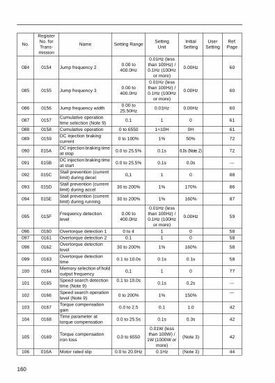
160
084 0154 Jump frequency 20.00 to
400.0Hz
0.01Hz (less than 100Hz) / 0.1Hz (100Hz
or more)
0.00Hz 60
085 0155 Jump frequency 30.00 to
400.0Hz
0.01Hz (less than 100Hz) / 0.1Hz (100Hz
or more)
0.00Hz 60
086 0156 Jump frequency width0.00 to
25.50Hz0.01Hz 0.00Hz 60
087 0157Cumulative operation time selection (Note 9)
0.1 1 0 61
088 0158 Cumulative operation 0 to 6550 1=10H 0H 61
089 0159DC injection braking current
0 to 100% 1% 50% 72
090 015ADC injection braking time at stop
0.0 to 25.5% 0.1s 0.0s (Note 2) 72
091 015BDC injection braking time at start
0.0 to 25.5% 0.1s 0.0s ---
092 015CStall prevention (current limit) during decel
0,1 1 0 88
093 015DStall prevention (current limit) during accel
30 to 200% 1% 170% 86
094 015EStall prevention (current limit) during running
30 to 200% 1% 160% 87
095 015FFrequency detection level
0.00 to 400.0Hz
0.01Hz (less than 100Hz) / 0.1Hz (100Hz
or more)
0.00Hz 59
096 0160 Overtorque detection 1 0 to 4 1 0 58097 0161 Overtorque detection 2 0.1 1 0 58
098 0162Overtorque detection level
30 to 200% 1% 160% 58
099 0163Overtorque detection time
0.1 to 10.0s 0.1s 0.1s 58
100 0164Memory selection of hold output frequency
0,1 1 0 77
101 0165Speed search detection time (Note 9)
0.1 to 10.0s0.1s 0.2s ---
102 0166Speed search operation level (Note 9)
0 to 200% 1% 150%---
103 0167Torque compensation gain
0.0 to 2.5 0.1 1.0 42
104 0168Time parameter at torque compensation
0.0 to 25.5s 0.1s 0.3s 42
105 0169Torque compensation iron loss
0.0 to 6550
0.01W (less than 100W) /
1W (1000W or more)
(Note 3) 42
106 016A Motor rated slip 0.0 to 20.0Hz 0.1Hz (Note 3) 44
No.
Register No. for Trans-mission
Name Setting RangeSetting
UnitInitial
SettingUser
SettingRef. Page

161
107 016BMotor resistance for one-phase
0.000 to 65.50Ω
0.001Ω (less than 10Ω) /
0.01Ω (10Ω or more)
(Note 3) 44
108 016C Motor leak inductance0.00 to
655.0mH
0.01mH (less than 100mH) / 0.1mH (100mH
or more)
(Note 3) 44
No.
Register No. for Trans-mission
Name Setting RangeSetting
UnitInitial
SettingUser
SettingRef. Page

162
Fourth Functions (Parameters n120 to n179)
109 016DTorque compensation voltage limiter
0 to 250% 1% 150% –
110 016E Motor no-load current 0 to 99% 1% (Note 3) 44111 016F Slip compensation gain 0.0 to 2.5 0.1 0.0 89
112 0170Slip compensation primary delay time
0.0 to 25.5s 0.1s 2.0s 89
113 0171Slip compensation selection during regeneration
0,1 1 0 ---
115#2
0173 Stall prevention automatic decrease selection
0,1 1 0 87
116#2
0174Accel/decel time during stall prevention
0,1 1 0 88
No.
Register No. for Trans-mission
Name Setting RangeSetting
UnitInitial
SettingUser
SettingRef. Page
120 0178 Frequency reference 90.00 to
400.0Hz
0.01Hz (less than 100Hz) / 0.1Hz (100Hz
or more)
0.00Hz 51
121 0179 Frequency reference 100.00 to
400.0Hz
0.01Hz (less than 100Hz) / 0.1Hz (100Hz
or more)
0.00Hz 51
122 017A Frequency reference 110.00 to
400.0Hz
0.01Hz (less than 100Hz) / 0.1Hz (100Hz
or more)
0.00Hz 51
123 017B Frequency reference 120.00 to
400.0Hz
0.01Hz (less than 100Hz) / 0.1Hz (100Hz
or more)
0.00Hz 51
124 017C Frequency reference 130.00 to
400.0Hz
0.01Hz (less than 100Hz) / 0.1Hz (100Hz
or more)
0.00Hz 51
125 017D Frequency reference 140.00 to
400.0Hz
0.01Hz (less than 100Hz) / 0.1Hz (100Hz
or more)
0.00Hz 51
126 017E Frequency reference 150.00 to
400.0Hz
0.01Hz (less than 100Hz) / 0.1Hz (100Hz
or more)
0.00Hz 51
No.
Register No. for Trans-mission
Name Setting RangeSetting
UnitInitial
SettingUser
SettingRef. Page

163
127 017F Frequency reference 160.00 to
400.0Hz
0.01Hz (less than 100Hz) / 0.1Hz (100Hz
or more)
0.00Hz 51
128 0180 PID control selection 0 to 8 1 0 110129 0181 PID feedback gain 0.00 to 10.00 0.01 1.00 113130 0182 Proportional gain (P) 0.0 to 25.0 0.1 1.0 111131 0183 Integral time (I) 0.0 to 360.0 0.1s 1.0 111132 0184 Derivative time (D) 0.00 to 2.50 0.01s 0.00 111133 0185 PID offset adjustment -100 to 100% 1% 0% 112134 0186 Integral (I) upper limit -100 to 100% 1% 100% 112
135 0187PID output primary delay parameter time
0.0 to 10.0 0.1s 0.0 112
136 0188PID feedback loss detection selection
0,1,2 1 0 113
137 0189PID feedback loss detection level
0 to 100% 1% 0% 113
138 018APID feedback loss detection time
0.0 to 25.5 0.1s 1.0 113
139 018BEnergy-saving control selection (V/f control mode)
0,1 1 0 105
140 018CEnergy-saving coefficient K2
0.0 to 6550 0.1 (Note 7) 105
141 018DEnergy-saving voltage lower limiter (at 60 Hz)
0 to 120% 1% 50% 106
142 018EEnergy-saving voltage lower limiter (at 6 Hz)
0 to 25% 1% 12% 106
143 018F Power average time 1 to 200 1 = 24ms 1 (24ms) 107
144 0190Search operation voltage limit
0 to 100% 1% 0% 107
145 0191Search operation voltage step (at 100%)
0.1 to 100% 0.1% 0.5% 107
146 0192Search operation voltage step (at 5%)
0.1 to 10.0% 0.1% 0.2% 107
149 0195 Pulse train input scaling 100 to 3300 1 (1 = 10Hz)2500
(25kHz)85
150 0196Pulse monitor output frequency selection
0,1,6,12,24,36 --- 0 66
No.
Register No. for Trans-mission
Name Setting RangeSetting
UnitInitial
SettingUser
SettingRef. Page

164
151 0197Timeover detection selection
0 to 4 1 0 94
152 0198
Setting unit selection of communications frequency reference/frequency monitor
0, 1, 2, 3 1 0 94
153 0199 Slave address 0 to 32 1 0 94154 019A Baud rate selection 0 to 3 1 2 94155 019B Parity selection 0, 1, 2 1 2 94156 019C Send waiting time 10 to 65ms 1ms 10ms 94157 019D RTS control 0, 1 1 0 94
158 019EMotor code (energy-saving control)
0 to 70 1 (Note 7) 105
159 019FEnergy-saving voltage upper limit (at 60Hz)
0 to 120% 1% 120% 106
160 01A0Energy-saving voltage upper limit (at 6Hz)
0 to 25% 1% 16% 106
161 01A1Search operation power detection hold width
0 to 100% 1% 10% 108
162 01A2Power detection filter time parameter
0 to 255 1 = 4 ms 5 (20ms) 108
163 01A3 PID output gain 0.0 to 25.0 0.1 1.0 113164 01A4 PID feedback selection 0 to 5 1 0 110
165 01A5Overheat protect select for installed braking resistor (Note 9)
0,1 1 0 61
166 01A6Input open-phase detection level (Note 9)
0 to 100% 1% 0% ---
167 01A7Input open-phase detection time (Note 9)
0 to 255,s 1,s 0,s ---
168 01A8Output open-phase detection level (Note 9)
0 to 100% 1% 0% ---
169 01A9Input open-phase detection time (Note 9)
0 to 2,0,s 0.1,s 0.0,s ---
175#1#2
01AFReducing carrier frequency selection at low speed
0,1 10
(Note 10)70
176 01B0Parameter copy selection
rdy,rEd,CPyvFy,vA,Sno
--- rdy 116
177 01B1Prohibiting parameter read selection
0,1 1 0 117
178 01B2 Fault history
Stores, displays most
recent 4 alarms
Setting disabled
– 36
179 01B3 Software No.Displays lower-place 4 digits
of software No.
Setting disabled
– –
No.
Register No. for Trans-mission
Name Setting RangeSetting
UnitInitial
SettingUser
SettingRef. Page

165
Notes: 1. Not initialized by parameter initalization.
2. Upper limit and initial setting of setting range are doubled at 400 class.
3. Changes depending on inverter capacity. Refer to the next page.
4. Changes depending on inverter capacity. Refer to page 64.
5. Initial setting of the model with operator JVOP-140 (with potentiometer) is 0. Setting can be set to 1 by parameter initialization.
6. When control mode selection (n002) is changed, initial setting correspondents to the control mode.
7. Changes depend on inverter capacity. Refer to page 101.
8. Setting value only applies to 200/400V class 7.5/10hp (5.5/7.5kW) inverters.
9. Parameter value only applies to 200/400V class 7.5/10hp (5.5/7.5kW) inverters
10. “1” for 200/400V class 7.5/10hp (5.5/7.5kW) inverters
* Values are double with 400V class.
Initial settings that change with inverter capacity
• 200V class 3-phase
No. NameV / f control mode
(n002 = 0)Vector control mode
(n002 = 1)n014 Mid. output frequency 1.3Hz 3.0Hzn015 Mid. output frequency voltage 12.0V* 11.0V*n016 Minimum output frequency 1.3Hz 1.0Hzn017 Minimum output frequency voltage 12V* 4.3V*n104 Torque compensation time parameter 0.3s 0.2sn111 Slip compensation gain 0.0 1.0n112 Slip compensation gain time parameter 2.0s 0.2s
No. Name Unit Factory setting– Inverter capacity kW 0.1kW 0.25kW 0.55kW 1.1kW 1.5kW 2.2kW – 3.7kW 5.5kW 7.5kW
n036 Motor rated current A 0.6 1.1 1.9 3.3 6.2 8.5 – 14.1 19.6 26.6
n105Torque compensation iron loss
W 1.7 3.4 4.2 6.5 11.1 11.8 – 19 28.8 43.9
n106 Motor rated slip Hz 2.5 2.6 2.9 2.5 2.6 2.9 – 3.3 1.5 1.3
n107Motor resistance for one phase*
Ω 17.99 10.28 4.573 2.575 1.233 0.8 – 0.385 0.199 0.111
n108Motor leakage inductance
MH 110.4 56.08 42.21 19.07 13.4 9.81 – 6.34 4.22 2.65
n110Motor no-load current
% 72 73 62 55 45 35 – 32 26 30

166
• 200V class single-phase
• 400V class 3-phase
* Values of motor line-to-line resistance are set to half of the standard value.= Values between V/f mode and Vector control mode.
No. Name Unit Factory setting– Inverter capacity kW 0.1kW 0.25kW 0.55kW 1.1kW 1.5kW 2.2kW – 3.7kW 5.5kW 7.5kW
n036 Motor rated current A 0.6 1.1 1.9 3.3 6.2 8.5 – 14.1 9.8 13.3
n105Torque compensation iron loss
W 1.7 3.4 4.2 6.5 11.1 11.8 – 19 28.8 43.9
n106 Motor rated slip Hz 2.5 2.6 2.9 2.5 2.6 2.9 – 3.3 1.5 1.3
n107Motor resistance for one phase*
Ω 17.99 10.28 4.573 2.575 1.233 0.8 – 0.385 0.797 0.443
n108Motor leak inductance
MH 110.4 56.08 42.21 19.07 13.4 9.81 – 6.34 16.87 10.59
n110Motor no-load current
% 72 73 62 55 45 35 – 32 26 30
No. Name Unit Factory setting– Inverter capacity kW – 0.37kW 0.55kW 1.1kW 1.5kW 2.2kW 3.0kW 3.7kW 5.5kW 7.5kW
n036 Motor rated current A – 0.6 1.0 1.6 3.1 4.2 7.0 7.0 9.8 13.3
n105Torque compensation iron loss
W – 3.4 4.0 6.1 11.0 11.7 19.3 19.3 28.8 43.9
n106 Motor rated slip Hz – 2.5 2.7 2.6 2.5 3.0 3.2 3.2 1.5 1.3
n107Motor resistance for one phase*
Ω – 41.97 19.08 11.22 5.044 3.244 1.514 1.514 0.797 0.443
n108Motor leak inductance
MH – 224.3 168.8 80.76 53.25 40.03 24.84 24.84 16.87 10.59
n110Motor no-load current
% – 73 63 52 45 35 33 33 26 30

tive
and ey its
and ey
167
Appendix - CE ConformanceCE Conformance - Low Voltage Directive (LVD) Compliance
c These circuits are hazardous and are separated from accessibility by protecseparation.
d These circuits are not separated from hazardous circuits by protective separation, but only with basic insulation. These circuits cannot be accessedmust not be interconnected with any circuits which are accessible, unless thare isolated from accessible circuits by supplemental insulation. These circucan be connected only to the following circuits:
30VDC or less (overvoltage category 2)
250 VAC or less (overvoltage category 2)
e These circuits are not separated from hazardous circuits by protective separation, but only with basic insulation. These circuits cannot be accessedmust not be interconnected with any circuits which are accessible, unless thare isolated from accessible circuits by supplemental insulation.

s
r sible. rter
el. le, ected
ts
168
CE Conformance - Electro-Magnetic Compatibility (EMC) Compliance
In order to conform to EMC standards, exclusive-use methods are required for linefilter application, cable shielding and inverter installation. An outline of the methodfollows.
The line filter and the inverter must be mounted on the same metal plate. The filteshould be mounted as close to the inverter as practical. Keep cable as short as posThe metal plate should be securely grounded. The ground of the line filter and invemust be bonded to the metal plate with as much area as possible.
For line power input cable, screened cable is recommended at least within the panThe screen of the cable should be connected to a solid ground. For the motor cabscreened cable (max. 20m) must be used and the screen of the motor cable is connto ground at both ends by a short connection, using as large an area as practical.
For a more detailed explanation, please refer to Making YASKAWA Inverter ProducConfirm with EMC Directive (G-TI#99012-V7).
The following table and figures show the line filter list for EMC standards and the installation/wiring of inverter and line filter.
Line Filter List for EMC Conformance
Recommended Line Filters for VS-606 made by Rasmi Electronics Ltd( 200V single phase )
Rated Voltage: AC 250V single phase
Ambient Temperature: 40°C (max.)
VS-606V7 ModelCurrent
(A)Weight
(kg)Dimension
W×D×H
CIMR-V7AUB0P1
CIMR-V7AUB0P2 RS 1010-V7 10 0.6 71 x 45 x 169
CIMR-V7AUB0P4
CIMR-V7AUB0P7 RS 1020-V7 20 1.0 111 x 50 x 169
CIMR-V7AUB1P5
CIMR-V7AUB2P2 RS 1030-V7 30 1.1 144 x 50 x 174
CIMR-V7AUB3P7 RS 1040-V7 40 1.2 174 x 50 x 174

169
Recommended Line Filters for VS-606V7 made by Rasmi Electronic Ltd( 200 V three phase)
Rated Voltage: AC 250V three phase
Ambient Temperature: 40×C (max.)
Recommended Line Filters for VS-606V7 made by Rasmi Electronic Ltd( 400 V three phase)
Rated Voltage: AC 480V three phase
Ambient Temperature: 40×C (max.)
VS-606V7 ModelCurrent
(A)Weight
(kg)Dimension
W×D×H
CIMR-V7AU20P1
CIMR-V7AU20P2 RS 2010-V7 10 0.8 82 x 50 x 194
CIMR-V7AU20P4
CIMR-V7AU20P7
CIMR-V7AU21P5 RS 2020-V7 16 1.0 111 x 50 x 169
CIMR-V7AU22P2
CIMR-V7AU23P7 RS 2030-V7 26 1.1 144 x 50 x 174
VS-606V7 ModelCurrent
(A)Weight
(kg)Dimension
W×D×H
CIMR-V7AU40P2 RS 3005-V7 5 1.0 111 x 45 x 169
CIMR-V7AU40P4
CIMR-V7AU40P7
CIMR-V7AU41P5 RS 3010-V7 10 1.0 111 x 45 x 169
CIMR-V7AU42P2
CIMR-V7AU43P7 RS 3020-V7 20 1.1 144 x 50 x 174

170
VS-606V7
PE L1 L2/N U V WPE
L1L2/NPEMains
Screendinput cable Footprint
Filter
LoadMotor Cable
screened
L1L2/N
PE
L1L2
PE
FILTER
3~M
Appendix 1.2
Installation of Line Filterand VS-606V7 ( single phase )
PE
VS-606V7
Woven Screened input cabl e
Woven Screened Motor cable

171
VS-606V7
P E L1 L2 L3 U V WP E
L1 L2P E
Mains
Screendinput cable
FootprintFilter
LoadMotor Cable
screened
L1
L2 L3P E
L1L2
P E
FILTER
3~M
Appendix 1.3
Installation of Line Filterand VS-606V7 ( 3 phase )
P E
VS-606V7
L3
L3
Woven Screened input cabl e
Woven Screened Motor cable

nd
re
a /rated er s of E
t all
rred
(e.g. st may
or
The ion tions
the
ted for up . You
172
Safety Warnings and Operating Information for Inverters
IntroductionDepending on their protection rating configuration, parts of inverters can have live, uninsulated ahot surfaces during operation. If housing components, the control unit or terminal covers are removed, incorrect installation and operation can lead to serious injuries and damage to other installations. It is thus absolutely essential to observe all the warnings and instructions in the operating manual. Installation, setup and maintenance should only be performed by properly qualified staff. IEC 364 / Cenelec HD 384 or DIN VDE 0100 and IEC 664 or DIN VDE. The applicable national safety and accident prevention regulations must also be observed.) For the purpose of observance of the safety requirement qualified staff are defined as individuals who afamiliar with the installation, setup and operation of the converters and who have the proper qualifications for this work.
Proper use for intended purposeInverters are designed for installation in electrical systems or machines. A converter installed in machine may only be activated if the machine conforms to the provisions of EU directive 89/392EEC (machine directives). EN 60204 must also be observed. The converter may also only be opeif the requirements of the EMC directive (89/336/EEC) are also satisfied. This frequency convertconforms to the requirements of the low voltage directive, 73/23/EEC. The harmonized standardthe prEN 50178/DIN VDE 0160 series have been applied, in combination with EN 660439-1 / VD06600 Part 500 and EN 60146 / VDE 0558. The specifications on the ratings plate and the specifications and connection requirements described in the documentation must be observed atimes.
Transportation and storageAll instructions for transport, storage and proper handling must be observed. Climatic and environmental conditions must conform to the requirements of prEN 50178.
InstallationThe converters must be installed and cooled in compliance with the regulations outlines and refeto in the documentation. The cooling air flow direction is an important requirement that must be observed. This means that the unit may only be installed and operated in the specified orientationupright). All distances specified must also be observed. The converters must be protected againexcessive stresses. No components may be bent and no distances required for proper insulationbe changed. To prevent the risk of static electricity damage never touch electronic components contacts.
Electrical connectionsAll national safety regulations (e.g. VBG 4) must be observed when working on live equipment. electrical installation of the units must conform to the applicable regulations. For further informatplease refer to the documentation. In particular, please take care to observe all installation instrucregarding proper EMC immunity, e.g. for shielding, earthing, location of filters and cable routing.This also applies for equipment with CE approvals. Compliance with the EMC legislation limits is responsibility of the machine or system manufacturer.
RCCBsFor information on the use of RCCBs with inverters please contact your supplier or Yaskawa representative.
OperationIn some systems it may be necessary to install additional monitoring and protective facilities to comply with the applicable safety and accident prevention regulations. The only changes permitare to the operator software of the inverters. Please note that the capacitors can remain chargedto around 5 minutes after the frequency converter has been disconnected from the power supplyshould thus always wait for a short period before opening the unit and touching the electrical connections.
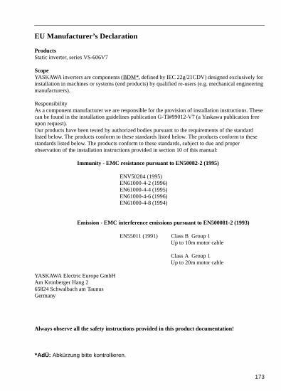
ering
ese e
rd se
173
EU Manufacturer’s Declaration
ProductsStatic inverter, series VS-606V7
ScopeYASKAWA inverters are components (BDM*, defined by IEC 22g/21CDV) designed exclusively for installation in machines or systems (end products) by qualified re-users (e.g. mechanical enginemanufacturers).
ResponsibilityAs a component manufacturer we are responsible for the provision of installation instructions. Thcan be found in the installation guidelines publication G-TI#99012-V7 (a Yaskawa publication freupon request).Our products have been tested by authorized bodies pursuant to the requirements of the standalisted below. The products conform to these standards listed below. The products conform to thestandards listed below. The products conform to these standards, subject to due and proper observation of the installation instructions provided in section 10 of this manual:
Immunity - EMC resistance pursuant to EN50082-2 (1995)
ENV50204 (1995)EN61000-4-2 (1996)EN61000-4-4 (1995)EN61000-4-6 (1996)EN61000-4-8 (1994)
Emission - EMC interference emissions pursuant to EN500081-2 (1993)
EN55011 (1991) Class B Group 1Up to 10m motor cable
Class A Group 1Up to 20m motor cable
YASKAWA Electric Europe GmbHAm Kronberger Hang 265824 Schwalbach am TaunusGermany
Always observe all the safety instructions provided in this product documentation!
*AdÜ: Abkürzung bitte kontrollieren.

YASKAWA ELECTRIC AMERICA, INC.Chicago-Corporate Headquarters 2121 Norman Drive South, Waukegan, IL 60085, U.S.A.Phone: (847) 887-7000 Fax: (847) 887-7310 Internet: http://www.yaskawa.comMOTOMAN INC.805 Liberty Lane, West Carrollton, OH 45449, U.S.A.Phone: (937) 847-6200 Fax: (937) 847-6277YASKAWA ELECTRIC CORPORATIONNew Pier Takeshiba South Tower, 1-16-1, Kaigan, Minatoku, Tokyo, 105-0022, JapanPhone: 81-3-5402-4511 Fax: 81-3-5402-4580 Internet: http://www.yaskawa.co.jpYASKAWA ELETRICO DO BRASIL COMERCIO LTDA.Avenida Fagundes Filho, 620 Bairro Saude Sao Paolo-SP, Brasil CEP: 04304-000Phone: 55-11-5071-2552 Fax: 55-11-5581-8795 E-mail: [email protected] ELECTRIC EUROPE GmbHAm Kronberger Hang 2, 65824 Schwalbach, GermanyPhone: 49-6196-569-300 Fax: 49-6196-888-301MOTOMAN ROBOTICS ABBox 504 S38525, Torsas, SwedenPhone: 46-486-48800 Fax: 46-486-41410MOTOMAN ROBOTEC GmbHKammerfeldstraβe 1, 85391 Allershausen, GermanyPhone: 49-8166-900 Fax: 49-8166-9039YASKAWA ELECTRIC UK LTD.1 Hunt Hill Orchardton Woods Cumbernauld, G68 9LF, Scotland, United KingdomPhone: 44-12-3673-5000 Fax: 44-12-3645-8182YASKAWA ELECTRIC KOREA CORPORATIONPaik Nam Bldg. 901 188-3, 1-Ga Euljiro, Joong-Gu, Seoul, KoreaPhone: 82-2-776-7844 Fax: 82-2-753-2639YASKAWA ELECTRIC (SINGAPORE) PTE. LTD.Head Office: 151 Lorong Chuan, #04-01, New Tech Park Singapore 556741, SINGAPOREPhone: 65-282-3003 Fax: 65-289-3003TAIPEI OFFICE (AND YATEC ENGINEERING CORPORATION)10F 146 Sung Chiang Road, Taipei, TaiwanPhone: 886-2-2563-0010 Fax: 886-2-2567-4677YASKAWA JASON (HK) COMPANY LIMITEDRm. 2909-10, Hong Kong Plaza, 186-191 Connaught Road West, Hong KongPhone: 852-2803-2385 Fax: 852-2547-5773BEIJING OFFICE Room No. 301 Office Building of Beijing International Club,21 Jianguomanwai Avenue, Beijing 100020, ChinaPhone: 86-10-6532-1850 Fax: 86-10-6532-1851SHANGHAI OFFICE 27 Hui He Road Shanghai 200437 ChinaPhone: 86-21-6553-6600 Fax: 86-21-6531-4242SHANGHAI YASKAWA-TONJI M & E CO., LTD.27 Hui He Road Shanghai 200437 ChinaPhone: 86-21-6533-2828 Fax: 86-21-6553-6677BEIJING YASKAWA BEIKE AUTOMATION ENGINEERING CO., LTD.30 Xue Yuan Road, Haidian, Beijing 100083 China Phone: 86-10-6232-9943 Fax: 86-10-6234-5002SHOUGANG MOTOMAN ROBOT CO., LTD.7, Yongchang-North Street, Beijing Economic & Technological Development Area,Beijing 100076 ChinaPhone: 86-10-6788-0551 Fax: 86-10-6788-2878
Yaskawa Electric America, Inc., December 1999 YEA-TOA-S606-11A Printed In U.S.A.