VS-606V7 Series INSTRUCTION MANUAL - · PDF fileVS-606V7 Series INSTRUCTION MANUAL COMPACT...
176
YASKAWA MANUAL NO. TOE-S606-11E VS-606V7 Series INSTRUCTION MANUAL COMPACT GENERAL-PURPOSE INVERTER (VOLTAGE VECTOR CONTROL) Upon receipt of the product and prior to initial operation, read these instructions thoroughly, and retain for future reference.
Transcript of VS-606V7 Series INSTRUCTION MANUAL - · PDF fileVS-606V7 Series INSTRUCTION MANUAL COMPACT...

YASKAWA
MANUAL NO. TOE-S606-11E
VS-606V7 Series
INSTRUCTION MANUALCOMPACT GENERAL-PURPOSE INVERTER(VOLTAGE VECTOR CONTROL)
Upon receipt of the product and prior to initial operation, readthese instructions thoroughly, and retain for future reference.

PREFACE
2
YASKAWA’s VS-606V7 is a small and simple inverter;as easy as using a contactor. This instruction manualdescribes installation, maintenance and inspection,troubleshooting, and specifications of the VS-606V7.Read this instruction manual thoroughly beforeoperation.
YASKAWA ELECTRIC CORPORATION
General Precautions
• Some drawings in this manual are shown with the protective cover orshields removed in order to describe detail with more clarity. Makesure all covers and shields are replaced before operating this product.
• This manual may be modified when necessary because of theimprovement of the product, modification, or changes inspecifications.Such modifications are denoted by a revised manual No.
• To order a copy of this manual, or if your copy has been damaged orlost, contact your YASKAWA representative.
• YASKAWA is not responsible for any modification of the productmade by the user, since that will void the guarantee.

NOTES FOR SAFE OPERATION
Read this instruction manual thoroughly before installation, operation,maintenance or inspection of the VS-606V7. In this manual, NOTES FORSAFE OPERATION are classified as “WARNING” or “CAUTION.”
Indicates a potentially hazardous situation which, if not avoided, couldresult in death or serious injury to personnel.
Indicates a potentially hazardous situation which, if not avoided, may resultin minor or moderate injury to personnel or damage to equipment.It may also be used to alert against unsafe practices.
Even items described in may result in a vital accident in somesituations. In either case, follow these important notes.
: These are steps to be taken to insure proper operation.
CAUTION
3
WARNING
CAUTION
NOTE

4
WARNINGS FOR UL/cUL MARKING• Do not connect or disconnect wiring, or perform signal checks while the
power supply is turned ON.• The Inverter internal capacitor is still charged even after the power supply
is turnd OFF. To prevent electric shock, disconnect all power beforeservicing the Inverter. Then wait at least one minute after the powersupply is disconnected and all indecators are OFF.
• Do not perform a withstand voltage test on any part of the Inverter. Thiselectronic equipment uses semiconductors and is vulnerable to highvoltage.
• Do not remove the Digital Operator or the blank cover unless the powersupply is turned OFF. Never touch the printed control board (PCB) whilethe power supply is turned ON.
• This Inverter is not suitable for use on a circuit capable of delivering morethan 18,000 RMS symmetrical amperes, 250volts maximum (200V classunits) or 18,000 RMS symmetrical amperes, 480volts maximum (400Vclass units).
CAUTION
Use 75°C copper wires or equivalent.
WARNINGS FOR CE MARKINGS• Only basic insulation to meet the requirements of protection class 1 and
overvoltage category II is provided with control circuit terminals.Additional insulation may be necessary in the end product to conform toCE requirements.
• For 400 V class Inverters, make sure to ground the supply neutral toconform to CE requirements.
• For conformance to EMC directives, refer to the relevant manuals for therequirements.Document No. EZZ008389 for Japanese version,Document No. EZZ008390 for English version

5
RECEIVINGCAUTION
(Ref. page)• Do not install or operate any inverter which is damaged or
has missing parts.Failure to observe this caution may result in personal injury or equipment damage.÷÷÷÷÷÷÷÷÷÷÷÷÷÷÷÷÷÷÷÷÷÷÷÷÷÷÷÷÷÷÷÷÷÷÷÷÷÷÷÷16
CAUTION
(Ref. page)
• Lift the cabinet by the cooling fin. When moving the unit, never lift by the plastic case or the terminal covers.Otherwise, the main unit may be dropped causing damage to the unit.÷÷÷÷÷÷÷÷÷÷÷÷÷÷÷÷÷÷÷÷÷÷÷÷÷÷÷÷÷÷÷÷÷÷÷÷÷÷÷÷÷÷÷÷÷÷20
• Mount the inverter on nonflammable material (i.e. metal).Failure to observe this caution can result in a fire.÷÷÷÷÷÷÷÷÷÷÷÷÷÷÷20
• When mounting units in an enclosure, install a fan orother cooling device to keep the intake air temperature below50: (122<) for IP20 (open chassis type), or below 40°C (105°F) for NEMA 1 (TYPE 1), IP20 (Top-closed type).Overheating may cause a fire or damage to the unit.÷÷÷÷÷÷÷÷÷÷÷÷÷21
• The VS-606V7 generates heat. For effective cooling, mount it vertically.Refer to the figure in “Mounting Dimensions” on page 21.
MOUNTING

WIRING
6
WARNING
(Ref. page)
• Only commence wiring after verifying that the powersupply is turned OFF.Failure to observe this warning can result in an electric shock or a fire.÷÷÷÷÷÷÷÷÷÷÷÷÷÷÷÷÷÷÷÷÷÷÷÷÷÷÷÷÷÷÷÷÷÷÷÷÷÷÷÷÷÷÷÷÷÷÷÷÷24
• Wiring should be performed only by qualified personnel.
Failure to observe this warning can result in an electric shock
or a fire.÷÷÷÷÷÷÷÷÷÷÷÷÷÷÷÷÷÷÷÷÷÷÷÷÷÷÷÷÷÷÷÷÷÷÷÷÷÷÷÷÷÷÷÷÷÷÷÷÷24• When wiring the emergency stop circuit, check the wiring
thoroughly before operation.Failure to observe this warning can result in personal injury.÷÷÷÷÷÷24
• Make sure to ground the ground terminal according to the
local grounding code.
Failure to observe this warning can result in an electric shock
or a fire.÷÷÷÷÷÷÷÷÷÷÷÷÷÷÷÷÷÷÷÷÷÷÷÷÷÷÷÷÷÷÷÷÷÷÷÷÷÷÷÷÷÷÷÷÷÷÷÷÷28• For 400V class, make sure to ground the supply neutral.
Failure to observe this warning can result in an electric shock
or a fire.÷÷÷÷÷÷÷÷÷÷÷÷÷÷÷÷÷÷÷÷÷÷÷÷÷÷÷÷÷÷÷÷÷÷÷÷÷÷÷÷÷÷÷÷÷÷÷÷÷28

7
CAUTION
(Ref. page)
• Verify that the inverter rated voltage coincides with theAC power supply voltage.Failure to observe this caution can result in personal injuryor a fire.
• Do not perform a withstand voltage test of the inverter.It may cause semi-conductor elements to be damaged.
• To connect a braking resistor, braking resistor unit orbraking unit, follow the procedures described inthis manual.Improper connection may cause a fire.÷÷÷÷÷÷÷÷÷÷÷÷÷÷÷÷÷÷÷÷÷÷÷÷÷28
• Make sure to tighten terminal screws of the main circuit and the control circuit.Failure to observe this caution can result in a malfunction, damage or a fire.÷÷÷÷÷÷÷÷÷÷÷÷÷÷÷÷÷÷÷÷÷÷÷÷÷÷÷÷÷÷÷÷÷÷÷÷÷÷÷÷÷÷24
• Never connect the AC main circuit power supply tooutput terminals U/T1, V/T2, W/T3.The inverter will be damaged and invalidate theguarantee.÷÷÷÷÷÷÷÷÷÷÷÷÷÷÷÷÷÷÷÷÷÷÷÷÷÷÷÷÷÷÷÷÷÷÷÷÷÷÷÷÷÷÷÷÷÷÷÷24
• Do not connect or disconnect wires or connectors while power is applied to the circuit.Failure to observe this caution can result in personal injury.
• Do not change signals during operation.The machine or the inverter may be damaged.

OPERATION
8
WARNING
(Ref. page)
• Only turn ON the input power supply after replacing the digital operator/blank cover (optional). Do not remove the digital operator or the covers while current is flowing.Failure to observe this warning can result in an electric shock.
• Never operate the digital operator or dip switches whenyour hand is wet.Failure to observe this warning can result in an electric shock.
• Never touch the terminals while current is flowing, even during inverter is stopping.Failure to observe this warning can result in an electric shock.
• When the fault retry function is selected, stand clear of the inverter or the load, since it may restart suddenly after being stopped.(Construct machine system, so as to assure safety for personnel, even if the inverter should restart.) Failure to observe this warning can result in personal injury.÷÷÷÷÷÷÷÷÷÷÷÷÷÷÷÷÷÷÷÷÷÷÷÷÷61
• When continuous operation after power recovery is selected, stand clear of the inverter or the load, since it may restart suddenly after being stopped. (Construct machine system, so as to assure safety for personnel, even if the inverter should restart.) Failure to observe this warning can result in personal injury.÷÷÷÷÷÷÷÷÷÷÷÷÷÷÷÷÷÷÷÷÷÷÷÷÷56
• Since the digital operator stop button can be disabled by a function setting, install a separate emergency stop switch.Failure to observe this warning can result in personal injury.
• If an alarm is reset with the operation signal ON, the inverterrestarts automatically. Only reset the alarm after verifying that the operation signal is OFF.Failure to observe this warning can result in personal injury.÷÷÷÷÷÷÷30

MAINTENANCE AND INSPECTION
9
CAUTION
(Ref. page)
• Never touch the heatsink since the temperature is very high.Failure to observe this caution can result in harmful burns to the body.
• Since it is easy to change operation speed from low tohigh, verify the safe working range of the motor andmachine before operation.Failure to observe this caution can result in personal injury and machine damage.
• Install a holding brake separately if necessary.Failure to observe this caution can result in personal injury.
• If using an Inverter with an elevator, take safety measures on theelevator to prevent the elevator from dropping.Failure to observe this caution can result in personal injury.
• Do not change signals during operation.The machine or the inverter may be damaged.
• All the constants of the inverter have been preset at the factory. Do not change the settings unnecessarily.The inverter may be damaged.÷÷÷÷÷÷÷÷÷÷÷÷÷÷÷÷÷÷÷÷÷÷÷÷÷÷÷÷÷÷÷31
WARNING
• Never touch high-voltage terminals in the inverter.Failure to observe this warning can result in an electrical shock
• Disconnect all power before performing maintenance or inspection.Then wait at least one minute after the power supply is disconnectedand all LEDs and CHARGE LED are extinguished.The capacitors are still charged and can be dangerous.

10
WARNING
• Never modify the product.Failure to observe this warning can result in an electrical shock orpersonal injury and will invalidate the guarantee.
WARNING
(Ref. page)
• Do not perform withstand voltage test on any part of the VS-606V7.This electronic equipment uses semiconductors and is vulnerable to highvoltage.
• Only authorized personnel should be permitted to performmaintenance, inspections or parts replacement.[Remove all metal objects (watches, bracelets, etc.) before operation.] (Use tools which are insulated against electrical shock.)Failure to observe this warning can result in an electric shock.÷÷÷÷÷÷131
CAUTION
(Ref. page)
• The control PC board employs CMOS ICs. Do not touch the CMOS elements. They are easily damaged by static electricity.
• Do not connect or disconnect wires, connectors, or cooling fanwhile power is applied to the circuit.Failure to observe this caution can result in personal injury.÷÷÷÷÷÷÷÷131
Others

WARNING DISPLAYA warning label is displayed on the front cover of the inverter, as shownbelow. Follow these instructions when handling the inverter.
11
PLASTICCASE TOP COVER
NAMEPLATE
STATUSINDICATORLAMP
WARNINGDISPLAY
QUALIFICATION MARK
Warning Display

12
CONTENTSNOTES FOR SAFE OPERATION••••••••••••••••••••••••••••••3
1. RECEIVING•••••••••••••••••••••••••••••••••••••••••••••••••••••••••••••16 Checking the Name Plate ••••••••••••••••••••••••••••••••••••••••••••••16
2. IDENTIFYING THE PARTS••••••••••••••••••••••••••••••••••17
3. MOUNTING•••••••••••••••••••••••••••••••••••••••••••••••••••••••••••••20 Choosing a Location to Mount the Inverter•••••••••••••••••••••••••20
Mounting Dimensions••••••••••••••••••••••••••••••••••••••••••••••••••••21
Mounting/Removing Components ••••••••••••••••••••••••••••••••••••22
4. WIRING••••••••••••••••••••••••••••••••••••••••••••••••••••••••••••••••••••24 Wiring Instructions ••••••••••••••••••••••••••••••••••••••••••••••••••••••••24
Wire and Terminal Screw Sizes•••••••••••••••••••••••••••••••••••••••25
Wiring the Main Circuit ••••••••••••••••••••••••••••••••••••••••••••••••••28
Wiring the Control Circuit •••••••••••••••••••••••••••••••••••••••••••••••29
Wiring Inspection••••••••••••••••••••••••••••••••••••••••••••••••••••••••••30
5. OPERATING THE INVERTER ••••••••••••••••••••••••••••31 Test Run ••••••••••••••••••••••••••••••••••••••••••••••••••••••••••••••••••••31
Selecting rotation direction •••••••••••••••••••••••••••••••••••••••••••••32
Operating the Digital Operator ••••••••••••••••••••••••••••••••••••••••33
LED Description •••••••••••••••••••••••••••••••••••••••••••••••••••••••••••35
Simple Data Setting ••••••••••••••••••••••••••••••••••••••••••••••••••••••40
6. PROGRAMMING FEATURES •••••••••••••••••••••••••••••41 Constant Set-up and Initialization ••••••••••••••••••••••••••••••••••••41
Using V/f Control Mode ••••••••••••••••••••••••••••••••••••••••••••••••••42
Using Vector Control Mode•••••••••••••••••••••••••••••••••••••••••••••45
Switching LOCAL/REMOTE Modes••••••••••••••••••••••••••••••••••48
Selecting Run/Stop Commands••••••••••••••••••••••••••••••••••••••••49
Selecting Frequency Reference•••••••••••••••••••••••••••••••••••••••50
Setting Operation Condition•••••••••••••••••••••••••••••••••••••••••••51
Reverse run prohibit••••••••••••••••••••••••••••••••••••••••••••••••••••51
Multi-step speed selection ••••••••••••••••••••••••••••••••••••••••••••51

13
Operating at low speed •••••••••••••••••••••••••••••••••••••••••••••••52
Adjusting speed setting signal ••••••••••••••••••••••••••••••••••••••53
Adjusting frequency upper and lower limits •••••••••••••••••••••••54
Using four accel/decel times ••••••••••••••••••••••••••••••••••••••••••55
Automatic restart after momentary power loss •••••••••••••••••••56
Soft-start characteristics ••••••••••••••••••••••••••••••••••••••••••••••••57
Torque detection •••••••••••••••••••••••••••••••••••••••••••••••••••••••••58
Frequency detection •••••••••••••••••••••••••••••••••••••••••••••••••••••59
Jump frequencies ••••••••••••••••••••••••••••••••••••••••••••••••••••••••61
Continuing operation by automatic fault reset •••••••••••••••••••••61
Operating coasting motor without trip •••••••••••••••••••••••••••••••62
Holding accel/decel temporarily ••••••••••••••••••••••••••••••••••••••63
Using frequency meter or ammeter ••••••••••••••••••••••••••••••••••64
Calibrating frequency meter or ammeter •••••••••••••••••••••••••••64
Using analog output (AM-AC) as a pulse signal output •••••••••65
Reducing motor noise or leakage current •••••••••••••••••••••••••67
Operator stop key selection •••••••••••••••••••••••••••••••••••••••••••69
Selecting Stopping Method ••••••••••••••••••••••••••••••••••••••••••••70
Selecting stopping method ••••••••••••••••••••••••••••••••••••••••••••70
Applying DC injection braking•••••••••••••••••••••••••••••••••••••••••71
Building Interface Circuits with External Devices •••••••••••••••••72
Using input signals ••••••••••••••••••••••••••••••••••••••••••••••••••••••72
Using multi-function analog input ••••••••••••••••••••••••••••••••••76
Using output signals ••••••••••••••••••••••••••••••••••••••••••••••••••••78
Setting Frequency by Current Reference Input ••••••••••••••••••80
Frequency Reference by Pulse Train Input •••••••••••••••••••82
Preventing Motor from Stalling (Current Limit) •••••••••••••••••••83
Stall prevention during running ••••••••••••••••••••••••••••••••••••84
Decreasing Motor Speed Fluctuation••••••••••••••••••••••••••••••••86
Slip compensation••••••••••••••••••••••••••••••••••••••••••••••••••••••••86
Motor Protection ••••••••••••••••••••••••••••••••••••••••••••••••••••••••••87
Motor overload detection •••••••••••••••••••••••••••••••••••••••••••••••87

14
Selecting Cooling Fan Operation •••••••••••••••••••••••••••••••••••••89
Using MEMOBUS (MODBUS) Communications ••••••••••••••••89
MEMOBUS(MODBUS) communications •••••••••••••••••••••••••••89
Communication specifications ••••••••••••••••••••••••••••••••••••••••90
Communication connection terminal ••••••••••••••••••••••••••••••••90
Procedure for communications with PLC ••••••••••••••••••••••••••90
Setting constants necessary for communication ••••••••••••••••91
Message format •••••••••••••••••••••••••••••••••••••••••••••••••••••••••92
Storing constants [Enter command] ••••••••••••••••••••••••••••••••98
Performing self-test ••••••••••••••••••••••••••••••••••••••••••••••••••••100
Using Energy-saving Control Mode ••••••••••••••••••••••••••••••••101Energy saving search operation•••••••••••••••••••••••••••••••••••••103Motor code ••••••••••••••••••••••••••••••••••••••••••••••••••••••••••••••105
Using PID Control Mode ••••••••••••••••••••••••••••••••••••••••••106Selecting PID control selection ••••••••••••••••••••••••••••••••••••••106PID Control Block Diagram •••••••••••••••••••••••••••••••••••••••••110Operator Analog Speed Reference Block Diagram ••••••••••••111
Using Constant Copy Function ••••••••••••••••••••••••••••••••••••••112Constant copy function ••••••••••••••••••••••••••••••••••••••••••••••••112READ function•••••••••••••••••••••••••••••••••••••••••••••••••••••••••••114COPY function ••••••••••••••••••••••••••••••••••••••••••••••••••••••••••115VERIFY function ••••••••••••••••••••••••••••••••••••••••••••••••••••••••117Inverter capacity display ••••••••••••••••••••••••••••••••••••••••••••••118Software No. display ••••••••••••••••••••••••••••••••••••••••••••••••••119
Unit selection for Frequency Reference Setting/Display •••••121
Selecting Processing for Frequency Reference Loss (n064) •••123
Input/Output Open-phase Detection••••••••••••••••••••••••••••••••124
Undertorque Detection ••••••••••••••••••••••••••••••••••••••••••••••125
Using Inverters for Elevating Machines••••••••••••••••••••••••••••127

15
7. MAINTENANCE AND INSPECTION ••••••••••••••••131 Periodical Inspection ••••••••••••••••••••••••••••••••••••••••••••••••••131 Part Replacement •••••••••••••••••••••••••••••••••••••••••••••••••••••131
8. FAULT DIAGNOSIS •••••••••••••••••••••••••••••••••••••••••••134 Protective and Diagnostic Function •••••••••••••••••••••••••••••••••134
Troubleshooting••••••••••••••••••••••••••••••••••••••••••••••••••••••••••143
9. SPECIFICATION••••••••••••••••••••••••••••••••••••••••••••••••••145 Standard Specifications (200V Class)••••••••••••••••••••••••••••••145
Standard Specifications (400V Class)••••••••••••••••••••••••••••••146
Standard Wiring••••••••••••••••••••••••••••••••••••••••••••••••••••••••••151
Sequence input connection with NPN/PNP transistor••••••••••154
Dimensions/Heat Loss •••••••••••••••••••••••••••••••••••••••••••••••••156
Recommended Peripheral Devices •••••••••••••••••••••••••••••••••158
Constants List ••••••••••••••••••••••••••••••••••••••••••••••••••••••••••••160

1. RECEIVING
After unpacking the VS-606V7, check the following :
Verify that the part numbers match your purchase order or packing slip. Check the unit for physical damage that may have occurred during
shipping.
If any part of VS-606V7 is missing or damaged, call for service immediately.
Checking the Name Plate
16
C I M R — V 7 A C 2 0 P 1
Inverter
VS-606V7 Series
MODEL
No.ABC
TypeWith digital operator (with potentiometer)Without digital operator (with blank cover)With digital operator (without potentiometer)
No. B 2 4
Voltage ClassSingle-phase 200VACThree-phase 200VACThree-phase 400VAC
No. C
SpecificationsEuropean standards
Note: Contact your YASKAWA representatives for the type without heatsink.
2 0 P 1 0SPEC
B24
Single-phase 200VACThree-phase 200VACThree-phase 400VAC
No. Protective structureOpen chassis(IP20)Enclosed wall-mounted*
Open chassis (IP20)Top-closed type
0
1
7
* NEMA 1 (TYPE 1) is optional.
INVERTER MODEL
MASS
INPUT SPEC.OUTPUT SPEC.
LOT NO.SERIAL NO. SOFTWARE NO.
0P10P20P40P71P52P23P04P0
200V class 0.1kW 0.25kW 0.55kW 1.1kW 1.5kW 2.2kW
4.0kW
400V class
0.37kW 0.55kW 1.1kW 1.5kW 2.2kW 3.0kW 4.0kW
Applicable maximum motor output
0P10P20P40P71P52P23P04P0
200V class 0.1kW 0.25kW 0.55kW 1.1kW 1.5kW 2.2kW
4.0kW
400V class
0.37kW 0.55kW 1.1kW 1.5kW 2.2kW 3.0kW 4.0kW
Applicable maximum motor output
Example of 3-phase, 200VAC, 0.1kW (0.13HP)

2. IDENTIFYING THE PARTS
17
Digital operator(with potentiometer)JVOP-140Used for setting orchanging constants.Frequency can be setusing potentiometer.
Digital operator(without potentiometer)JVOP-147Used for setting orchanging constants.
Blank cover In models without adigital operator, theblank cover is mountedin place of the digitaloperator.
DIGITALOPERATOR
FRONTCOVER
NAME PLATE
HEATSINK
FAN COVERCOOLING FAN
GROUNDTERMINAL
TERMINAL COVER
WIRING HOLESFOR CONTROLCIRCUIT
WIRING HOLESFOR MAINCIRCUIT
BOTTOMCOVER
STOPRESET
DSPL
><
RUN
DATAENTER
FREF FOUT IOUT
F/R LO/RE
MNTR
PRGM
MIN MAX
DIGITALOPERATORJVOP-140
STOPRESET
DSPL
><
RUN
DATAENTER
FREF FOUT IOUT
F/R LO/RE
MNTR
PRGM
DIGITALOPERATORJVOP-147
TOP COVER

VS-606V7 inverters with the covers removed
18
11
2212 13 14
1 2 3
OM
RO
N G
5S
2
1
STOPRESET
DSPL
><
RUN
DATAENTER
FREF FOUT IOUT
F/R LO/RE
MNTR
PRGM
MIN MAX
DIGITALOPERATORJVOP-140
SHORT -CIRCUITBAR
FREQUENCY SETTING POTENTIOMETER
STATUS DISPLAY LAMPTERMINAL RESISTOR SWITCH FORCOMMUNICATION CIRCUITVOLTAGE/CURRENT CHANGE SWITCH FOR ANALOG FREQUENCY REFERENCE INPUT
CONTROL CIRCUIT TERMINAL BLOCK
GROUND TERMINAL
MAIN CIRCUIT TERMINAL BLOCK
INPUT POLARITY SWITCH
Example of 3-phase (200V class,1.5kW) inverter
11
2212 13 14
1 2 3
OM
RO
N G
5S
5.5mm
STOPRESET
DSPL
><
RUN
DATAENTER
FREF FOUT IOUT
F/R LO/RE
MNTR
PRGM
MIN MAX
DIGITALOPERATORJVOP-140
GROUND TERMINAL
INPUT POLARITY SWITCH
FREQUENCY SETTING POTENTIOMETERSTATUS DISPLAY LAMPTERMINAL RESISTOR SWITCH FOR COMMUNICATION CIRCUITVOLTAGE/CURRENT CHANGE SWITCH FOR ANALOG FREQUENCY REFERENCE INPUTCONTROL CIRCUIT TERMINAL BLOCK
MAIN CIRCUIT TERMINAL BLOCK
Example of 3-phase (200V class,0.1kW) inverter
SHORT -CIRCUITBAR

Main Circuit Terminal ArrangementTerminal arrangement of the main circuit terminal differs depending on theinverter model.
19
R/L1 S/L2 T/L3
+2 B1 B2
+1 U/T1 V/T2 W/T3
R/L1 S/L2 T/L3 B1 B2 U/T1 V/T2 W/T3
+1 +2
R/L1 S/L2 T/L3 W/T3B2 U/T1 V/T2+1 +2 B1
R/L1 S/L2 W/T3B2 U/T1 V/T2+1 +2 B1
CIMR-V7∗C20P1 to 20P7, B0P1 to B0P4
CIMR-V7∗C21P5, 22P2, B0P7, B1P5, 40P2 to 42P2
CIMR-V7∗C24P0, B2P2, 43P0, 44P0
CIMR-V7∗CB4P0

20
Choosing a Location to Mount the InverterBe sure the inverter is protected from the following conditions :
Extreme cold and heat. Use only within the ambient temperature range :
-10 to +50; (14 to 122,) for IP20 (open chassis type),
-10 to +40˚C (14 to 105˚F) for NEMA 1 (TYPE 1), IP 20 (Top-closed type)
Rain, moisture
Oil sprays, splashes
Salt spray
Direct sunlight. (Avoid using outdoors)
Corrosive gases (e.g. sulfurized gas) or liquids
Dust or metallic particles in the air.
Physical shock, vibration.
Magnetic noise. (Example : welding machines, power devices, etc.)
High humidity.
Radioactive substances.
Combustibles : thinner, solvents, etc.
3. MOUNTING

Mounting Dimensions
To mount the VS-606V7, dimensions as shown below are required.
21
30mm(1.18 in.)
OR MORE
30mm(1.18 in.)
OR MORE AIR100mm (3.94 in.)OR MORE
100mm (3.94 in.)OR MORE
AIR

22
Mounting / Removing Components
• Removing front coverUse a driver to loosen the screwon the front cover surface todirection 1 to remove it. Thenpress the right and left sides todirection 2 and lift the front coverto direction 3.
• Mounting front coverMount the front cover in thedescending order of the aboveprocedure for removal.
• Removing terminal coverAfter removing the front cover,press the right and left sides todirection 1 and lift the terminalcover to direction 2.
• Mounting terminal coverMount the terminal cover in thedescending order of the aboveprocedure for removal.
Removing and Mounting Digital Operator and Covers

23
• Removing digital operatorAfter removing the front cover,lift the upper and lower sides(section A) of the right side of thedigital operator to direction 1.
• Mounting digital operatorMount the digital operator in thedescending order of the aboveprocedure for removal.
• Removing bottom coverAfter removing the front coverand the terminal cover, tilt thebottom cover to direction 1 withsection A as a supporting point.
• Mounting bottom coverMount the bottom cover in thedescending order of the aboveprocedure for removal.

4. WIRING
Wiring Instructions
(1) Always connect the power supply (for main circuit inputs) and powerinput terminals R/L1, S/L2, and T/L3 (R/L1, S/L2 for single-phase) via amolded-case circuit breaker (MCCB) or a fuse. Never connect them toterminals U/T1,V/T2,W/T3, B1, B2, -, +1, or +2. The inverter may bedamaged.Refer to page 148 for Recommended Peripheral Devices.For single-phase inverters, always use terminal R/L1 and S/L2. Never connect to terminal T/L3.
Inverter Power Supply Connection Terminals
200V 3-phase Input Power SupplySpecification ProductCIMR-V7??2???Connect to R/L1,S/L2, T/L3 Connect to R/L1, S/L2
200V Single Input Power Supply Specification Product CIMR-V7??B???
Connect to R/L1, S/L2, T/L3
400V 3-phase Input Power Supply Specification Product CIMR-V7??4???
(2) Connect the motor wiring to terminals U/T1, V/T2, W/T3 on the maincircuit output side (bottom of the inverter).
(3) If the wiring distance between inverter and motor is long, reduce theinverter carrier frequency. For details, refer to “Reducing motor noiseor leakage current (n080)” on page 67.
(4) Control wiring must be less than 50m (164ft) in length and separate fromthe power wiring. Use twisted-pair shielded wire when inputting the fre-quency signal externally.
(5) Tighten the screws on the main circuit and control circuit terminals.
(6) Do not connect or disconnect wiring, or perform signal check while thepower supply is turned ON.
(7) For 400V class inverters, make sure to ground the supply neutral to con-form to CE requirements.
(8) Only basic insulation to meet the requirements of protection class 1 andovervoltage category II is provided with control circuit terminals.Additional insulation may be necessary in the end product to conform toCE requirements.
(9) A closed-loop connector should be used when wiring to the main circuitterminal.
24

25
(10) Voltage drop should be considered when determining wire size.Voltage drop can be calculated using the following equation:
Phase-to phase voltage drop (V) = √3 wire resistance (Ω/km) × wiring distance (m) × current (A) × 10-3
Select a wire size so that voltage drop will be less than 2% of thenormal rated voltage.
Wire and Terminal Screw Sizes
Model
Common to all models
Terminal Symbol
MA, MB, MCS1 to S7,P1,P2,SC,PC,R+,R-S+,S-,FS,FR,FC,AM,AC,RP
Screwtwisted wiresingle
mm2mm2
WireRecommended sizeApplicable size
Applicable size Recommended size
AWGAWG0.5 to 1.250.5 to 1.25
twisted wiresingle
0.5 to 0.750.5 to 1.25
20 to 1620 to 16
20 to 1820 to 16
Shielded wire or
equivalent
1. Control Circuit
Model Terminal Symbol Screw
2. Main Circuit
R/L1,S/L2,T/L3,–,+1,+2,B1,B2,U/T1,V/T2,W/T3
0.8 to 1.0(7.1 to 8.88)
0.8 to 1.0(7.1 to 8.88)
0.8 to 1.0(7.1 to 8.88)
0.8 to 1.0(7.1 to 8.88)
1.2 to 1.5(10.65 to 13.31)
0.75 to 2
0.75 to 2
0.75 to 2
0.75 to 2
2 to 5.5
18 to 14
18 to 14
18 to 14
18 to 14
14 to 10
2
2
2
2
14
14
14
14
600Vvinyl-
sheathedwire or
equivalent
200V Class 3-phase Input Series
Note : The wire size is set for copper wires at 75°C (160°F).
Tightening Torque
N • m (Ib • in)
Tightening TorqueN • m (Ib • in)
M3
M2
Type
mm2
Wire
AWG mm2 AWG Type
0.5 to 0.6(4.44 to 5.33)
0.22 to 0.25(1.94 to 2.21)
0.75
0.75
18
18
5.5 10
CIMR-V7*C20P1
R/L1,S/L2,T/L3,–,+1,+2,B1,B2,U/T1,V/T2,W/T3
CIMR-V7*C20P2
R/L1,S/L2,T/L3,–,+1,+2,B1,B2,U/T1,V/T2,W/T3
CIMR-V7*C20P4
R/L1,S/L2,T/L3,–,+1,+2,B1,B2,U/T1,V/T2,W/T3
CIMR-V7*C20P7
R/L1,S/L2,T/L3,–,+1,+2,B1,B2,U/T1,V/T2,W/T3
CIMR-V7*C24P0
M3.5
M3.5
M3.5
M3.5
M4
1.2 to 1.5(10.65 to 13.31) 2 to 5.5 14 to 10 3.5 12
R/L1,S/L2,T/L3,–,+1,+2,B1,B2,U/T1,V/T2,W/T3
CIMR-V7*C22P2
M4
1.2 to 1.5(10.65 to 13.31) 2 to 5.5 14 to 10
2 14
3.5 12
R/L1,S/L2,T/L3,–,+1,+2,B1,B2,U/T1,V/T2,W/T3
CIMR-V7*C21P5
M4

26
Applicable size Recommended sizeModel Terminal Symbol Screw
R/L1,S/L2,T/L3,–,+1,+2,B1,B2,U/T1,V/T2,W/T3
0.8 to 1.0(7.1 to 8.88)
0.8 to 1.0(7.1 to 8.88)
0.8 to 1.0(7.1 to 8.88)
1.2 to 1.5(10.65 to 13.31)
3.0(26.62)
1.2 to 1.5(10.65 to 13.31)
0.75 to 2
0.75 to 2
0.75 to 2
2 to 5.5
3.5 to 8
2 to 8
18 to 14
18 to 14
18 to 14
14 to 10
12 to 8
14 to 8
2
2
2
3.5
14
14
14
12
600Vvinyl-
sheathedwire or
equivalent
200V Class Single-phase Input Series
Note : 1. The wire size is set for copper wires at 75°C (160°F). 2. Three-phase input is also available for 0.1 to 1.1kW of single-phase input series.
Tightening Torque
N • m (lb • in) mm2
Wire
AWG mm2 AWG Type
8 8
CIMR-V7*CB0P1
R/L1,S/L2,T/L3,–,+1,+2,B1,B2,U/T1,V/T2,W/T3
CIMR-V7*CB0P2
R/L1,S/L2,T/L3,–,+1,+2,B1,B2,U/T1,V/T2,W/T3
CIMR-V7*CB0P4
R/L1,S/L2,T/L3,–,+1,+2,B1,B2,U/T1,V/T2,W/T3
CIMR-V7*CB0P7
R/L1,S/L2,-,+1,+2,B1,B2,U/T1,V/T2,W/T3
CIMR-V7*CB4P0
M3.5
M3.5
M3.5
M4
M5
M4
1.2 to 1.5(10.65 to 13.31) 2 to 5.5 14 to 10 5.5 10
R/L1,S/L2,-,+1,+2,B1,B2,U/T1,V/T2,W/T3
CIMR-V7*CB2P2
M4
1.2 to 1.5(10.65 to 13.31) 2 to 5.5 14 to 10 5.5 10
R/L1,S/L2,–,+1,+2,B1,B2,U/T1,V/T2,W/T3
CIMR-V7*CB1P5
M4
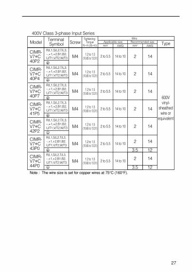
27
Applicable size Recommended sizeModel Terminal Symbol Screw
R/L1,S/L2,T/L3,–,+1,+2,B1,B2,U/T1,V/T2,W/T3
1.2 to 1.5(10.65 to 13.31)
1.2 to 1.5(10.65 to 13.31)
1.2 to 1.5(10.65 to 13.31)
1.2 to 1.5(10.65 to 13.31)
1.2 to 1.5(10.65 to 13.31)
2 to 5.5
2 to 5.5
2 to 5.5
2 to 5.5
2 to 5.5
14 to 10
14 to 10
14 to 10
14 to 10
14 to 10
2
2
2
2
14
14
14
14
600Vvinyl-
sheathedwire or
equivalent
400V Class 3-phase Input Series
Note : The wire size is set for copper wires at 75°C (160°F).
Tightening Torque
N • m (Ib • in) mm2
Wire
AWG mm2 AWG Type
2
3.5
14
12
CIMR-V7*C40P2
R/L1,S/L2,T/L3,–,+1,+2,B1,B2,U/T1,V/T2,W/T3
CIMR-V7*C40P4
R/L1,S/L2,T/L3,–,+1,+2,B1,B2,U/T1,V/T2,W/T3
CIMR-V7*C40P7
R/L1,S/L2,T/L3,–,+1,+2,B1,B2,U/T1,V/T2,W/T3
CIMR-V7*C41P5
R/L1,S/L2,T/L3,–,+1,+2,B1,B2,U/T1,V/T2,W/T3
CIMR-V7*C44P0
M4
M4
M4
M4
M4
1.2 to 1.5(10.65 to 13.31) 2 to 5.5 14 to 10 2
3.5
14
12
R/L1,S/L2,T/L3,–,+1,+2,B1,B2,U/T1,V/T2,W/T3
CIMR-V7*C43P0
M4
1.2 to 1.5(10.65 to 13.31) 2 to 5.5 14 to 10 2 14
R/L1,S/L2,T/L3,–,+1,+2,B1,B2,U/T1,V/T2,W/T3
CIMR-V7*C42P2
M4

Wiring the Main Circuit
28
MCCB orleakagebreaker
L1 L2 L3
Grounding
• Braking resistor connection (optional)To connect the braking resistor, cut theprotector on terminals B1 and B2. To protect the braking resistor fromoverheating, install a thermal overloadrelay between the braking resistor andthe inverter. This provides a sequencewhich shuts off the power supply, by athermal relay trip contact. Use this same procedure whenconnecting a braking resistor unit.Refer to page 152.
• Inverter outputConnect the motor terminals to U/T1,V/T2,W/T3.
• Wiring the main circuit terminalsPass the cables through wiring hole andconnect. Be sure to mount the cover inits original position.
Connect with a Phillips (plus) screwdriver.
GOOD GOOD POOR
[Example of 3-phase,
400V class, 0.37kW
inverters]
• Main circuit input power supply
Always connect the power supply line toinput terminals R/L1, S/L2, and T/L3[R/L1, S/L2 for single-phase inverters].Never connect them to terminalU/T1,V/T2,W/T3, B1, B2, -, +1, or +2.Otherwise the inverter may be damaged.
For single-phase inverters, alwaysuse terminals R/L1 and S/L2. Neverconnect to terminal T/L3.
• Grounding (Use ground terminal .)Make sure to ground the ground terminalaccording to the local groundingcode.Never ground the VS-606V7 in commonwith welding machines, motors, or otherelectrical equipment. When several VS-606V7 units are usedside by side, ground each unit as shownin examples. Do not loop the groundwires.
NOTE

Wiring the Control Circuit
Screwdriver blade width
Insert the wire into the lower part of the terminal block and connect ittightly with a screwdriver.
Wire sheath strip length must be 5.5mm (0.22in.).
29
• Control Circuit terminals
Wiring the control circuit terminals
Only basic insulation is provided for the control circuit terminals.Additional insulation may be necessary in the end product.
* SW1 can be changed according to sequence input signal (S1 to S7) polarity.0V common: NPN side (Initial setting) +24V common: PNP side Refer to pages 154 and 155 for SW1.Refer to pages 80 and 90 for SW2.
Pass the cable through wiring hole and connect. Be sure to mount the coverson the original position.
12 13 14 22
SW1 SW2PNPNPN
OFFV
ON1
2 I
1 2 3 11
MA MB MC
S5MA MBMC
S6 S7 P1 P2CONTACT OUTPUT
R R FS FR FCS2S1 S3 S4 SC PC S S AM AC RP
0.4 mm max(0.016 in.)
2.5 mm max(0.098 in.)
5.5 mm(0.22 in.)

30
Open the front cover and verify that the strip length is 5.5mm (0.22in.).
Wiring Inspection
After completing wiring, check the following :
Wiring is proper.
Wire clippings or screws are not left in the unit.
Screws are securely tightened.
Bare wire in the terminal does not contact other terminals.
If the FWD (REV) run command is given during the run command selection(n003=1) from the control circuit terminal, the motor will start automaticallyafter the main circuit input power supply is turned ON.
NOTE
S5MAMBMC
S6 S7 P1 P2CONTACT OUTPUT
R R FS FR FCS2S1 S3 S4 SC PC
SW1 SW2S S AM AC RP
SCALE
5.5 mm

31
5. OPERATING THE INVERTER
Initial setting of control mode selection (n002) is set at V/f control mode.
Test RunThe inverter operates by setting the frequency (speed).There are four types of operation modes for the VS-606V7 :
1 Run command from the digital operator (potentiometer/digital setting).
2 Run command from the control circuit terminal.
3 Run command from communications (MEMOBUS communications).
4 Run command from communication card (optional)
Prior to shipping, the drive is set up to receive run command and frequencyreference from the operator. Below are instructions for running the VS-606V7 using the digital operator JVOP-147 (without potentiometer). Forinstructions on operation, refer to page 40.
Operation reference or frequency reference constants can be selectedseparately as shown below.
Name
RunCommandSelection
FrequencyReferenceSelection
Constant
n003 = 0 --- Enables operator RUN, STOP/RESET = 1 --- Enables control circuit terminal run/stop = 2 --- Enables communications (MEMOBUS communications) = 3 --- Enables communication card (optional)
n004 = 0 --- Enables operator potentiometer = 1 --- Enables frequency reference 1 (constant n024) = 2 --- Enables voltage reference (0 to 10V) of control circuit terminal = 3 --- Enables current reference (4 to 20mA) of control circuit terminal = 4 --- Enables current reference (0 to 20mA) of control circuit terminal = 5 --- Enables pulse train reference of control circuit terminal = 6 --- Enables communications (MEMOBUS communications) = 7 --- Enables voltage reference (0 to 10V) of operator circuit terminal = 8 --- Enables current reference (4 to 20mA) of operator circuit terminal = 9 --- Enables communication card (optional)

32
Operation Steps
1. Turn ON the power supply.
7. Press to stop. STOP
Operator Display
LEDDisplay
Status IndicatorLED
2. Set constant n004 to 1.
3. Set the following constants.
4. Select forward or reverse run by pressing qor w key.
5. Set the reference by pressing q or w key.
6. Press .
15.05.0
6.00
1
60.00
0.0060.00
FREF
PRGM
FOUT
RUNALARM
RUNALARM
PRGMRUNALARMn019 : 15.0 (acceleration time)
n020 : 5.0 (deceleration time)
Examine the application.(Never select REV when reverse run is prohibited.)
RUN
FOUT
RUNALARM
FREFRUNALARM
RUNALARM
RUNALARM
F/R
60.000.00
(Forward)
(Reverse)
or
Status indicator lamp : Blinking: Blinking (Long Blinking) : OFF
NOTE
: ON
Selecting rotation directionIt is possible to select the direction in which the motor rotates when theFORWARD RUN command is executed.The motor rotates in the opposite direction when the REVERSE RUNcommand is executed.
Operation Check Points Motor rotates smoothly. Motor rotates in the correct direction. Motor does not have abnormal vibration or noise. Acceleration or deceleration is smooth. Current matching the load flows. Status indicator LED’s and digital operator display are correct.
n040 Setting
0
1
Description
The motor rotates in the counterclockwise direction as viewed from the load when the FORWARD RUN command is executed.
The motor rotates in the clockwise direction as viewed from the load when the FORWARD RUN command is executed.

33
Operating the Digital Operator
All functions of the VS-606V7 are set by the digital operator. Below aredescriptions of the display and keypad sections.
DIGITAL OPERATOR JVOP-140
STOPRESET
DSPL
><
RUN
DATAENTER
FREF FOUT IOUT
F/R LO/RE
MNTR
PRGM
DIGITALOPERATORJVOP-140
Function display LED’sLED switches to another function each time DSPL is pressed.The displayed data can be changed.
Press to switch between function LEDs.
Press to enter the constant data. (Displays the constant data when selecting constant no. by PRGM LED.)
Press to increase constant no./data value.
Press to stop the motor. (Press to reset at faults.)
Press to runthe motor.
Data display section Display section
Press to decrease constant no./data value.
Operator CN2 terminal
(Color in parenthesis indicates the color of LED.)
Status indicator(same function with RUN indicator)
FREFFrequency reference
setting/monitoring(GREEN)
FOUTOutput frequency
monitor(GREEN)
IOUTOutput current
monitor(GREEN)
F/ROperator RUN
command FWD/REV selection(GREEN)
PRGMConstant no./data
(RED)
MNTRMulti-function
monitor(GREEN)
LO/RELOCAL/REMOTE
Selection(RED)
CN2-1: Operator circuit terminal (voltage reference)
CN2-2: Operator circuit terminal (current reference)
CN2-3: GND for Operator circuit terminal
(Rear side of the operater)
Details of LEDs
STOPRESET
RUNMIN MAX
Frequency setting potentiometer Changes frequency setting according to the potentiometer.
Display section

34
RUN
ALARM
(Green)
(Red)
Operation ready(During Stop)
Normal
Operation
Ramp to
stop
: ON : BLINKING : OFF: BLINKING (Long Blinking)
NOTE
Description of Status Indicator LEDs
There are two LEDs on the middle right section of the face of the VS-606V7.The inverter status is indicated by various combinations of ON, BLINKINGand OFF LEDs. RUN indicator and status indicator on the RUN buttonhave the same function.
For details on how the status indicator LED’s function at inverter faults,refer to Section 8 “FAULT DIAGNOSIS” on page 134. If a fault occurs,the ALARM LED lights.
The fault can be reset by turning ON the fault reset signal (or pressing
key on the digital operator) with the operation signal OFF or by
turning OFF the power supply. If the operation signal is ON, the fault
cannot be reset by the fault reset signal.
STOPRESET

LED DescriptionBy pressing on the digital operator, each of the function LEDs can be
selected.
The following flowchart describes each function LED.
DSPL
35
If the VS-606V7loses power while inone of these modes,it will return to thismode once power isrestored.
Power ON
FREF
FOUT
IOUT
MNTR
F/R
DSPL
DSPL
DSPL
DSPL
DSPL
Frequency reference setting/monitor (Hz)Sets VS-606V7 operation speed.
Output frequency monitor (Hz)Displays frequency that VS-606V7 is currently outputting.Setting disabled.
Output current monitor (A)Displays current that VS-606V7 is currently outputting.Setting disabled.
Multi-function monitorDescription of the selected monitor is displayed.(Refer to page 36 for details.)
FWD/REV run selectionSets the motor rotation direction when run command is given by the digital operator.Setting can be changed by or key.FO (forward run) EV (reverse run)
<<
Monitor No.U-01: Frequency reference (FREF)U-02: Output frequency (FOUT)U-03: Output current (IOUT) U-04: Output voltage reference (Unit: 1V)U-05: DC voltage (Unit: 1V)U-06: Input terminal statusU-07: Output terminal statusU-08: Torque monitor U-09: Fault historyU-10: Software No.U-11: Output power U-15: Data reception errorU-16: PID feedbackU-17: PID inputU-18: PID output

36
LO/RE
PRGM
DSPL
DSPL
LOCAL / REMOTE Selection
Constant No. / dataSets and changes data using constant No. (Refer to page 39.)
FREFReturn to
This function switches the operation; operation using the digital operator including frequency setting with potentiometer, or that using the input terminals or through communicationsSetting can be changed by or key.
(Local) (Remote)
<<
Multi-Function monitor
Press key. When is ON, datacan be displayed by selecting monitor No.
[Example] Monitoring Output Voltage Reference
DSPL MNTR
MNTR
U - 0 4
ENTER MNTR
2 0 0
DSPL ENTERor
Select U-04 by pressing or key.^
^
Output voltage referenceis displayed.
MNTR
• Selecting monitor
DSPL
IOUT
DSPL
F/R

37
ConstantNo. Name Description
U-01
U-02
U-03
U-04
U-05
U-06
U-07
U-08
U-09
U-10
U-11
U-16
U-17
U-18
Frequency reference(FREF)
Output frequency(FOUT)
Output current(IOUT)
Output voltage
DC voltage
Input terminal status
Output terminal status
Torque monitor
Fault history (last 4 faults)
Software No.
Output power
Hz
Hz
A
V
V
---
---
%
---
---
kW
Frequency reference can be monitored. (Same as FREF)
Output frequency can be monitored. (Same as FOUT)
Output current can be monitored. (Same as IOUT)
Output voltage can be monitored.
Main circuit DC voltage can be monitored.
Input terminal status of control circuit terminalscan be monitored.
Output terminal status of control circuit terminals can be monitored.
The amount of output torque can be monitored.When V/f control mode is selected,“----” is displayed.
Last four fault history is displayed.
Software No. can be checked.
Output power can be monitored.
Input 100(%) / Max. output frequency or equivalent
±100(%)/± Max. output frequercy
±100(%)/± Max. output frequercy
U-15 Data reception error
PID feedback
PID input
PID output
Contents of MEMOBUS communication datareception error can be checked.(contents of transmission register No. 003DH are the same)
---
%
%
%
*1
*1
*1
*2
*2
*3
*4
*5
*5
*5
• MonitoringFollowing items can be monitored by U- constants.
*1 The status indicator LED is not turned ON.
*2 Refer to the next page for input / output terminal status.
*3 The display range is from -99.9kW to 99.99kW.
When regenerating, the output power will be displayed in units of 0.01kW
when -9.99kW or less and in units of 0.1kW when more than -9.99kW.
When in the vector control mode,“----”will be displayed.
*4 Refer to the next page for data reception error.
*5 Displayed in units of 0.1% when less than 100% and in units of 1% when
100% or more. The display range is from -999% to 999%.

Input / Output terminal status
38
1: Terminal S1 is “closed.”
Input terminal status
1: Terminal S2 is “closed.”1: Terminal S3 is “closed.”1: Terminal S4 is “closed.”1: Terminal S5 is “closed.”1: Terminal S6 is “closed.”1: Terminal S7 is “closed.”Not used
1: Terminal MA-MC is “closed.”
Output terminal status
1: Terminal P1-PC is “closed.”1: Terminal P2-PC “closed.”
Not used
1: CRC error
Data reception error display
1: Data length faultNot used1: Parity error1: Over run error1: Framing error1: TimeoverNot used

39
Setting and referring constants
Following shows how to select and change constants.
LO/RE
L O
PRGM
N 0 0 1
DSPL
DSPL
PRGM
N 0 0 3
ENTER PRGM
0
PRGM
1
ENTER
PRGM
1
PRGM
N 0 0 3
FREF
6 0.0 0
REMOTE/LOCALselection
ConstantNo./data
n003Operationreferenceselection
Initial setting:0operator reference
Set to 1Control circuitterminal reference(blinking at changing)
• Setting n003 (Run command selection)
Data setReturn toconstant No.display
Switching fault historyOrder of the fault history can be changed by or key.
Clearing fault historySet constant n001 to 6 to clear fault history. Display returns to n001 aftercompletion of 6 setting.Note: Constant initialize(n001=12,13) clears the fault history.
∨∨
Fault history display methodWhen U-09 is selected, a four-digit box is displayed. The three digits fromthe right show the fault description, and the digit on the left shows the orderof fault (from one to four). Number 1 represents the latest fault, and 2,3,4,in ascending order of fault occurrence.
(Example)<??? •••••• 4-digit numbers
< : Order of fault (1 to 4)??? : Fault description
"---" is displayed if there is no fault.(Refer to page 134 for details.)

Simple Data SettingDigital setting (Refer to 5. OPERATING THE INVERTER) andpotentiometer setting are both available for simple accel/decel operation ofthe VS-606V7.
Digital setting is set at the factory (n004=1). For the model with digitaloperator (with potentiometer) JVOP-140, factory setting is set by frequencysetting potentiometer (n004=0).
Following is an example in which the function LED’s are used to setfrequency reference, acceleration time, deceleration time, and motordirection.
40
Operation Steps OperatorDisplay
12-LEDDisplay
StatusIndicator LED
RUNALARM
Status indicator lamp : ON : Blinking : OFF
1. Turn the potentiometer fully to the left. Then, turn the power ON.
2. F/R blinks. Select FWD/REV run using keys.
Never select REV when reverse run is prohibited.
3. Press DSPL to blink FREF. Then press RUN.
4. Operates the motor by turning thepotentiometer to the right. (Frequency reference corresponds to the potentiometer position is displayed.)
If the potentiometer is switched rapidly, the motor also accelerates or decelerate rapidly corresponding to the potentiometer movement. Pay attention to load status and switch the potentiometer with the speed not to affect motor movement.
0.00
FORorREV
0.00 to 60.00Minimumoutputfrequency is1.50Hz
FREF
RUNALARM
RUNALARM
NOTE
0.00 RUNALARM
F/R
FREF
FREF
NOTE
Data setting by frequency setting potentiometer

6. PROGRAMMING FEATURESFactory settings of the constants are shown as in the tables.
Constant Set-up and Initialization
The following table describes the data which can be set or read when n001is set.Unused constants among n001 to n179 are not displayed.
“ ” appears on the LED display for one second and the set data returns to itsinitial values in the following cases :
(1) The set values of multi-function input selection 1 to 7 (n050 to n056) are the same.(2) If the following conditions are not satisfied in the V/f pattern setting :
Max. output frequency (n011) Max. voltage output frequency (n013)> Mid. output frequency (n014) Min. output frequency (n016)
For details, refer to “Adjusting torque according to application” (V/f pattern setting) on page 42.(3) If the following conditions are not satisfied in the Jump frequency setting :
Jump frequency 3 (n085) Jump frequency 2 (n084) Jump frequency 1 (n083)
(4) If Frequency reference lower limit (n034) Frequency reference upper limit (n033)(5) If motor rated current (n036) 150% of inverter rated current (6) Constant n018 is set to 1 (accel / decel time unit is 0.01sec.) when n018 is set to 0 and the
value exceeding 600.0sec. is set to accel / decel time (n019 to n022).
41
† Refer to page 73.* Excluding setting disabled constants.
n001 Setting
0 n001
Constant that can be set Constant that can be referred
1
2
3
4
5
6
7 to 11
12
13
n001 to n049 *
n001 to n079 *
n001 to n119 *
n001 to n179 *
Not used
Fault history cleared
Not used
Initialize
Initialize (3-wire sequence) †
n001 to n179
n001 to n049
n001 to n079
n001 to n119
n001 to n179
Constant selection/initialization (n001)
NOTE

42
Using V/f Control Mode
V/f control mode is preset at the factory.Control mode selection (n002)= 0: V/f control mode (initial setting)
1: Vector control mode
Adjust motor torque by using “V/f pattern” and “full-range automatic torqueboost”.
• V/f pattern settingSet V/f pattern by n011 to n017 as described below. Set each pattern whenusing a special motor (high-speed motor, etc.) or when requiring specialtorque adjustment of machine.
Be sure to satisfy the followingconditions for the setting of n011 ton017.n016 n014 < n013 n011If n016 = n014 is set, the set value ofn015 is disabled.
Adjusting torque according to application
ConstantsNo.
n011
n012
n013
n014
n015
n016
n017
Max. output frequency
Max. voltage
Max. voltage outputfrequency (base frequency)
Mid. output frequency
Mid. outputfrequency voltage
Min. output frequency
Min. outputfrequency voltage
Name Unit Setting rangeInitial
Setting
0.1Hz
1V
0.1Hz
0.1Hz
1V
0.1Hz
1V
50.0 to 400.0Hz 50.0Hz1 to 255.0V
(0.1 to 510.0V)
0.2 to 400.0Hz
0.1 to 399.9Hz
0.1 to 255.0V(0.1 to 510.0V)0.1 to 10.0Hz1 to 50.0V
(0.1 to 100.0V)
200.0V(400.0V)
50.0Hz
1.3Hz12.0V
(24.0V)1.3Hz12.0V
(24.0V)
V: (VOLTAGE)
n012
n015
n0170
n016 n013n014 n011 (FREQUENCY)f

43
• Typical setting of V/f patternSet the V/f pattern according to the application as described below. For400V class, the voltage values (n012, n015, and n017) should be doubled.When running at a frequency exceeding 50Hz/60Hz, change the maximumoutput frequency (n011).Note :Be sure to set the maximum output frequency according to the motor characteristics.
(1) For general-purpose applications
(2) For fans/pumps
(3) For applications requiring high starting torque
Increasing voltage of V/f pattern increases motor torque, but an excessiveincrease may cause motor overexcitation, motor overheat or vibration.
Note : n012 is to be set to motor rated voltage.
Constantn011n012n013n014n015n016n017
Setting60.0200.060.01.512.01.512.0
Constant Setting60.0200.060.030.050.01.510.0
n011n012n013n014n015n016n017
Constant Setting50.0200.050.025.050.01.310.0
n011n012n013n014n015n016n017
Constant Setting60.0200.060.03.024.01.518.0
n011n012n013n014n015n016n017
Constant Setting50.0200.050.02.524.01.318.0
n011n012n013n014n015n016n017
Motor Specification : 60Hz
Motor Specification : 60Hz Motor Specification : 50Hz
Motor Specification : 60Hz Motor Specification : 50Hz
V200
121.5 60 f
V200
50
121.5 30 60 f
V200
50
101.3 25 50 f
V200
2418
1.5 3 60 f
V200
2418
1.3 2.2 50 f
@@@@@@@@e?@@@@@@@@e?@@h?@@h?@@h?@@h?@@h?@@h?
@@@@@@@@e?@@@@@@@@?e@@@@@@@@e?@@@@@@@@?e@@@@@@@@e?@@@@@@@@?e@@@@@@@@e?@@@@@@@@?e@@@@@@@@e?@@@@@@@@?e@@@@@@@@e?@@@@@@@@?e@@@@@@@@e?@@@@@@@@?e@@@@@@@@e?@@@@@@@@?e@@@@@@@@e?@@@@@@@@?e@@@@@@@@e?@@@@@@@@?e@@@@@@@@e?@@@@@@@@?e@@@@@@@@e?@@@@@@@@?e@@@@@@@@e?@@@@@@@@?e@@@@@@@@e?@@@@@@@@?e@@@@@@@@e?@@@@@@@@?e@@@@@@@@e?@@@@@@@@?e@@@@@@@@e?@@@@@@@@?e@@@@@@@@e?@@@@@@@@?e@@@@@@@@e?@@@@@@@@?e@@@@@@@@e?@@@@@@@@?e@@@@@@@@e?@@@@@@@@?e@@@@@@@@e?@@@@@@@@?e@@@@@@@@e?@@@@@@@@?e@@@@@@@@e?@@@@@@@@?e@@@@@@@@e?@@@@@@@@?e@@@@@@@@e?@@@@@@@@?e@@@@@@@@e?@@@@@@@@?e@@@@@@@@e?@@@@@@@@?e@@@@@@@@e?@@@@@@@@?e@@@@@@@@e?@@@@@@@@?e@@@@@@@@e?@@@@@@@@?e@@@@@@@@e?@@@@@@@@?e@@@@@@@@e?@@@@@@@@?e@@@@@@@@e?@@@@@@@@?e@@@@@@@@e?@@@@@@@@?e@@@@@@@@e?@@@@@@@@e?@@@@@@@@?e@@@@@@@@e?@@@@@@@@?e@@@@@@@@e?@@@@@@@@?e@@@@@@@@e?@@@@@@@@?e@@@@@@@@e?@@@@@@@@?e@@@@@@@@e?@@@@@@@@?e@@@@@@@@e?@@@@@@@@?e@@@@@@@@e?@@@@@@@@?e@@@@@@@@e?@@@@@@@@?e@@@@@@@@e?@@@@@@@@?e@@@@@@@@e?@@@@@@@@?e@@@@@@@@e?@@@@@@@@?e@@@@@@@@e?@@@@@@@@?e@@@@@@@@e?@@@@@@@@?e@@@@@@@@e?@@@@@@@@?e@@@@@@@@e?@@@@@@@@?e@@@@@@@@e?@@@@@@@@?e@@@@@@@@e?@@@@@@@@?e@@@@@@@@e?@@@@@@@@?e@@@@@@@@e?@@@@@@@@?e@@@@@@@@e?@@@@@@@@?e@@@@@@@@e?@@@@@@@@?e@@@@@@@@e?@@@@@@@@?e@@@@@@@@e?@@@@@@@@?e@@@@@@@@e?@@@@@@@@?e@@@@@@@@e?@@@@@@@@?e@@@@@@@@e?@@@@@@@@?e@@@@@@@@e?@@@@@@@@?e@@@@@@@@e?@@@@@@@@?e@@@@@@@@e?@@@@@@@@?e@@@@@@@@e?@@@@@@@@?e@@@@@@@@e?@@@@@@@@?e@@@@@@@@e?@@@@@@@@?e@@@@@@@@e?@@@@@@@@?e@@@@@@@@e?@@@@@@@@?e@@@@@@@@e?
@@@@@@@@@@@@@@@@@@@@@@@@@@@@
@@@@@@@@@@@@@@@@
@@@@@@@@@@@@@@@@
@@@@@@@@@@@@@@@@
@@@@@@@@@@@@@@@@
@@@@@@@@@@@@@@@@
@@@@@@@@@@@@@@@@
@@@@@@@@@@@@@@@@
@@@@@@@@@@@@@@@@
@@@@@@@@@@@@@@@@
@@@@@@@@@@@@@@@@
@@@@@@@@@@@@@@@@
@@@@@@@@@@@@@@@@
@@@@@@@@@@@@@@@@
@@@@@@@@@@@@@@@@
@@@@@@@@@@@@@@@@
@@@@@@@@@@@@@@@@
@@@@@@@@@@@@@@@@
@@@@@@@@@@@@@@@@
@@@@@@@@@@@@@@@@
@@@@@@@@@@@@@@@@
@@@@@@@@@@@@@@@@
@@@@@@@@@@@@@@@@
@@@@@@@@@@@@@@@@
@@@@@@@@@@@@@@@@
@@@@@@@@@@@@@@@@
@@@@@@@@@@@@@@@@
@@@@@@@@@@@@@@@@
@@@@@@@@@@@@@@@@
@@@@@@@@@@@@@@@@
@@@@@@@@@@@@@@@@
@@@@@@@@@@@@@@@@
@@@@@@@@@@@@@@@@
@@@@@@@@@@@@@@@@
@@@@@@@@@@@@@@@@
@@@@@@@@@@@@@@@@
@@@@@@@@@@@@@@@@
@@@@@@@@@@@@@@@@
@@@@@@@@@@@@@@@@
@@@@@@@@@@@@@@@@
@@@@@@@@@@@@@@@@
@@@@@@@@@@@@@@@@
@@@@@@@@@@@@@@@@
@@@@@@@@@@@@@@@@
@@@@@@@@@@@@@@@@
@@@@@@@@@@@@@@@@
@@@@@@@@@@@@@@@@
@@@@@@@@@@@@@@@@
@@@@@@@@@@@@@@@@
@@@@@@@@@@@@@@@@
@@@@@@@@@@@@@@@@
?@@?@@?@@?@@?@@?@@
?@@@@@@@@?@@@@@@@@
?@@@@@@@@?e@@@@@@@@e?@@@@@@@@?e@@@@@@@@e?@@@@@@@@?e@@@@@@@@e?@@@@@@@@?e@@@@@@@@e?@@@@@@@@?e@@@@@@@@e?@@@@@@@@?e@@@@@@@@e?@@@@@@@@?e@@@@@@@@e?@@@@@@@@?e@@@@@@@@e?@@@@@@@@?e@@@@@@@@e?@@@@@@@@?e@@@@@@@@e?@@@@@@@@?e@@@@@@@@e?@@@@@@@@?e@@@@@@@@e?@@@@@@@@?e@@@@@@@@e?@@@@@@@@?e@@@@@@@@e?@@@@@@@@?e@@@@@@@@e?@@@@@@@@?e@@@@@@@@e?@@@@@@@@?e@@@@@@@@e?@@@@@@@@?e@@@@@@@@e?@@@@@@@@?e@@@@@@@@e?@@@@@@@@?e@@@@@@@@e?@@@@@@@@?e@@@@@@@@e?@@@@@@@@?e@@@@@@@@e?@@@@@@@@?e@@@@@@@@e?@@@@@@@@?e@@@@@@@@e?@@@@@@@@?e@@@@@@@@e?@@@@@@@@?e@@@@@@@@e?@@@@@@@@?e@@@@@@@@e?@@@@@@@@?e@@@@@@@@e?@@@@@@@@?e@@@@@@@@e?@@@@@@@@?e@@@@@@@@e?@@@@@@@@?e@@@@@@@@e?@@@@@@@@?e@@@@@@@@e?@@@@@@@@?e@@@@@@@@e?@@@@@@@@?e@@@@@@@@e?@@@@@@@@?e@@@@@@@@e?@@@@@@@@?@@@@@@@@?e@@@@@@@@e?@@@@@@@@?e@@@@@@@@e?@@@@@@@@?e@@@@@@@@e?@@@@@@@@?e@@@@@@@@e?@@@@@@@@?e@@@@@@@@e?@@@@@@@@?e@@@@@@@@e?@@@@@@@@?e@@@@@@@@e?@@@@@@@@?e@@@@@@@@e?@@@@@@@@?e@@@@@@@@e?@@@@@@@@?e@@@@@@@@e?@@@@@@@@?e@@@@@@@@e?@@@@@@@@?e@@@@@@@@e?@@@@@@@@?e@@@@@@@@e?@@@@@@@@?e@@@@@@@@e?@@@@@@@@?e@@@@@@@@e?@@@@@@@@?e@@@@@@@@e?@@@@@@@@?e@@@@@@@@e?@@@@@@@@?e@@@@@@@@e?@@@@@@@@?e@@@@@@@@e?@@@@@@@@?e@@@@@@@@e?@@@@@@@@?e@@@@@@@@e?@@@@@@@@?e@@@@@@@@e?@@@@@@@@?e@@@@@@@@e?@@@@@@@@?e@@@@@@@@e?@@@@@@@@?e@@@@@@@@e?@@@@@@@@?e@@@@@@@@e?@@@@@@@@?e@@@@@@@@e?@@@@@@@@?e@@@@@@@@e?@@@@@@@@?e@@@@@@@@e?@@@@@@@@?e@@@@@@@@e?@@@@@@@@?e@@@@@@@@e?@@@@@@@@?e@@@@@@@@e?@@@@@@@@?e@@@@@@@@e?@@@@@@@@?e@@@@@@@@e?@@@@@@@@?e@@@@@@@@e?@@@@@@@@
@@g@@g@@g@@g@@g@@g@@@@@@@@@@@@@@@@
@@@@@@@@@@@@@@@@
@@@@@@@@@@@@@@@@
@@@@@@@@@@@@@@@@
@@@@@@@@@@@@@@@@
@@@@@@@@@@@@@@@@
@@@@@@@@@@@@@@@@
@@@@@@@@@@@@@@@@
@@@@@@@@@@@@@@@@
@@@@@@@@@@@@@@@@
@@@@@@@@@@@@@@@@
@@@@@@@@@@@@@@@@
@@@@@@@@@@@@@@@@
@@@@@@@@@@@@@@@@
@@@@@@@@@@@@@@@@
@@@@@@@@@@@@@@@@
@@@@@@@@@@@@@@@@
@@@@@@@@@@@@@@@@
@@@@@@@@@@@@@@@@
@@@@@@@@@@@@@@@@
@@@@@@@@@@@@@@@@
@@@@@@@@@@@@@@@@
@@@@@@@@@@@@@@@@
@@@@@@@@@@@@@@@@
@@@@@@@@@@@@@@@@
@@@@@@@@@@@@@@@@
@@@@@@@@@@@@@@@@
@@@@@@@@@@@@@@@@
@@@@@@@@@@@@@@@@
@@@@@@@@@@@@@@@@
@@@@@@@@@@@@@@@@
@@@@@@@@@@@@@@@@
@@@@@@@@@@@@@@@@
@@@@@@@@@@@@@@@@
@@@@@@@@@@@@@@@@
@@@@@@@@@@@@@@@@
@@@@@@@@@@@@@@@@
@@@@@@@@@@@@@@@@
@@@@@@@@@@@@@@@@
@@@@@@@@@@@@@@@@
@@@@@@@@@@@@@@@@
@@@@@@@@@@@@@@@@
@@@@@@@@@@@@@@@@
@@@@@@@@@@@@@@@@
@@@@@@@@@@@@@@@@
@@@@@@@@@@@@@@@@
@@@@@@@@@@@@@@@@
@@@@@@@@@@@@@@@@
@@@@@@@@@@@@@@@@
@@@@@@@@@@@@@@@@
@@@@@@@@@@@@@@@@
Constant Setting50.0200.050.01.312.01.312.0
n011n012n013n014n015n016n017
Motor Specification : 50Hz(Factory setting)
V200
121.3 50 f

44
• Full-range automatic torque boost (when V/f mode is selected; n002=0)Motor torque requirement changes according to load conditions. Full-range automatic torque boost adjusts voltage of V/f pattern according tothe requirement. The VS-606V7 automatically adjusts the voltage duringconstant-speed operation as well as during acceleration. The required torque is calculated by the inverter. This ensures tripless operation and energy-saving effects.
Operation
Normally, no adjustment is necessary for torque compensation gain (n103factory setting : 1.0). When the wiring distance between the inverter and themotor is long, or when the motor generates vibration, change the automatictorque boost gain. In these cases, set the V/f pattern (n011 to n017).
Adjustment of torque compensation time constant (n104) and torquecompensation iron loss (n105) are normally not required.
Adjust torque compensation time constant under the following conditions:• Increase the setting when the motor generates vibration.• Reduce the setting when response is low.
Output voltage Torque compensation gain (n103) Required torque
f (FREQUENCY)
Required torque Increase voltageV(VOLTAGE)

Using Vector Control ModeSetting the control mode selection (n002) can use a vector control mode.
n002 = 0: V/f control mode (factory setting)1: Vector control mode
Precaution for voltage vector control applicationSince vector control needs motor constants, the YASKAWA standard motor constants have been set at the factory prior to shipment. Therefore,when an inverter exclusive-use motor is used or when a motor of anyother manufacturer is driven the required torque characteristics orspeed control characteristics may not be maintained because theconstants are not matched. Set the following constants so that they canmatch the motor constants.
No.
n106
n107
n036
n110
Name
Motor rated slip
Line to neutral (per phase)
Motor rated current
Motor no-load current
Unit
0.1Hz
0.1A
1%
0.001Ω(less than 10Ω)
0.01Ω(10Ω or more)
Setting range
0.0 to 20.0Hz
0.000 to 65.50Ω
0 to 150% of inverterrated current
0 to 99%(100%=motor rated current)
Initialsetting
*
*
*
* Setting depends on inverter capacity.
*
Adjustment of touque compensation gain (n103) and torquecompensation time constants (n104) is normally not required.
Adjust torque compensation time constant under the followingconditions:• Increase the setting when the motor generates vibration.• Reduce the setting when response is low.
To adjust for slip compensation gain (n111), induce load so that motorspeed reaches target value. Increase or decrease the value by 0.1.• When speed is less than target value, increase slip compensation
gain.• When speed is more than target value, reduce slip compensation
gain.
Adjustment of slip compensation time constant (n112) is normally notrequired.
Adjust under the following conditions:• Reduce the setting when response is low.• Increase the setting when speed is unstable.
45

46
Motor constant calculation
Following show an example of motor constant calculation.
Set n106 (motor rated slip), n036 (motor rated current), n107 (Line toneutral (per phase)) and n110 (motor no-load current) according to themotor test report.To connect a reactor between the inverter and the motor, set n108 to thevalue of “n108 (motor leakage inductance) initial value plus externally-mounted reactor inductance.„ Unless a reactor is connected, n108 (motorleakage inductance) does not have to be set according to the motor.
(1) Motor rated slip (n106)
120 × motor rated frequency (Hz)*1
Number of motor pole – Motor rated speed (r/min)*2
120 / Number of motor pole=
*1 Base frequency (Hz) during constant output control*2 Rated speed (r/min) at base frequency during constant output control
(3) Motor rated current (n036)
= Rated current at motor rated frequency (Hz)*1 (A)
Calculations are based on line-to-line resistance and insulation grade of the motor test report.
(E type insulation) Test report of line-to-line resistance at 75°C (Ω) × 0.92 ×
(B type insulation) Test report of line-to-line resistance at 75°C (Ω) × 0.92 ×
(F type insulation) Test report of line-to-line resistance at 115°C (Ω) × 0.87 ×
(2) Line to neutral (per phase) (n107)
× 100 (%)
(4) Motor no-load current (n110)
=No-load current (A) at motor rated frequency (Hz)*1
Rated current (A) at motor rated frequency (Hz)*1
21
21
21
n113 Setting
Select slip compensation status during regeneration:
01
Slip correction during regenerative operationDisabledEnabled
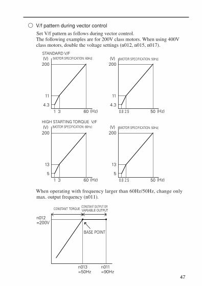
V/f pattern during vector control
Set V/f pattern as follows during vector control.The following examples are for 200V class motors. When using 400Vclass motors, double the voltage settings (n012, n015, n017).
47
200
11
4.31 3 60 (Hz)
(V)STANDARD V/F [MOTOR SPECIFICATION: 60Hz]
200
11
4.30.8 2.5 50 (Hz)
(V) [MOTOR SPECIFICATION: 50Hz]
200
13
51 3
n013=50Hz
n012=200V
n011=90Hz
BASE POINT
60 (Hz)
(V)HIGH STARTING TORQUE V/F [MOTOR SPECIFICATION: 60Hz]
200
13
50.8 2.5 50 (Hz)
(V) [MOTOR SPECIFICATION: 50Hz]
CONSTANT TORQUECONSTANT OUTPUT OR VARIABLE OUTPUT
When operating with frequency larger than 60Hz/50Hz, change only max. output frequency (n011).

48
How to select LOCAL/REMOTE modes
When LOCAL/REMOTEswitching function is notset for multi-functioninput selection
When LOCAL/REMOTEswitching function is setat multi-function inputselection
LOCAL mode REMOTE mode
(When 17 is set toany of constantsn050 to n056)
(When 17 is not setto any of constantsn050 to n056)
Switching LOCAL/REMOTE ModesThe following functions can be selected by switching the LOCAL orREMOTE mode. To select RUN/STOP commands or frequencyreference, change the mode in advance depending on the followingapplications.
• LOCAL mode: Enables the digital operator for RUN/STOPcommands and FWD/REV run commands.Frequency reference can be set by potentiometer or
.
• REMOTE mode: Enables run command selection (n003).
FREF
Set multi-functioninput terminal isturned OFF.
Set multi-functioninput terminal isturned ON.
Select rE for
operator
selection.LO/RE
Select Lo foroperator
selection.LO/RE

49
Selecting Run/Stop CommandsRefer to Switching LOCAL / REMOTE Modes (page 48) to selecteither the LOCAL mode or REMOTE mode.Operation method (RUN / STOP commands, FWD / REV runcommands) can be selected by the following method.
LOCAL modeWhen Lo (local mode) is selected for digital operator ON mode, or when LOCAL / REMOTE switching function is set and the inputterminals are turned ON, run operation is enabled by the or ofthe digital operator, and FWD/REV run is enabled by ON mode(using or key).
REMOTE mode• Select remote mode.
There are following two methods to select remote mode.1. Select rE (remote mode) for selection.2. When the local / remote switching function is selected for multi-
function input selection, turn OFF the input terminal to select remotemode.
• Select operation method by setting the constant n003.n003=0: Enables the digital operator (same with local mode)
=1: Enables the multi-function input terminal (see fig. below)=2: Enables communications (refer to page 89)=3: Enables communication card (optional)
• Example for using the multi-function input terminal as operationreference (two-wire sequence)
For example of three-wire sequence, refer to page 73.Note: When inverter is operated without the digital operator, always set
the constant n010 to 0.
LO / RE
>< F / R
RUNSTP
LO / RE
IM
S1S2SC
FWD RUN/STOPREV RUN/STOP
n003 : 1 (Initial setting : 0)n050 : 1 (Initial setting)n051 : 2 (Initial setting)

Operating (RUN / STOP commands) by communicationsSetting constant n003 to 2 in REMOTE mode can give RUN / STOPcommands by communication (MEMOBUS communications). For thecommand by communications, refer to page 89)
Selecting Frequency ReferenceFrequency reference can be selected by the following methods.
Setting by operatorSelect REMOTE or LOCAL mode in advance. For the method forselecting the mode, refer to page 48.
LOCAL modeSelect command method by constant n008.n008=0 : Enables the setting by potentiometer on digital operator.
=1 : Enables the digital setting by digital operator (Initial setting). Factory setting of the model with digital operator (with poten-tiometer) JVOP-140 is n008=0.
• Digital setting by digital operatorInput frequency while FREF is lit (press ENTER after setting the numericvalue).Frequency reference setting is effective when 1 (Initial setting : 0) is setto constant n009 instead of pressing ENTER key.n009=0 : Enables frequency reference setting by ENTER key.
=1 : Disables frequency reference setting by ENTER key.
REMOTE modeSelect command method by constant n004.n004=0 : Enables frequency reference setting by potentiometer on digital
operator.=1 : Frequency reference 1 (n024) is effective (Initial setting)
Factory setting of the model with digital operator (with poten-tiometer) JVOP-140 is n004=0.
=2 : Voltage reference (0 to 10V) (See the figure on page 51)=3 : Current reference (4 to 20mA) (Refer to page 80)=4 : Current reference (0 to 20mA) (Refer to page 80)=5 : Pulse train reference (Refer to page 82)=6 : Communication (Refer to page 89)=7 : Voltage reference of digital operator circuit terminal (0 to10)=8 : Current reference of digital operator circuit terminal (4 to 20mA)=9 : Communication card (optional)
50

By combining frequency reference and input terminal function selections,up to 16 steps of speed can be set.
8-step speed changen003=1 (operation mode selection ) n054=6 (Multi-function contact input terminal 5)n004=1 (Frequency reference selection ) n055=7 (Multi-function contact input terminal 6)n024=25.0Hz (Frequency reference 1) n056=8 (Multi-function contact input terminal 7)n025=30.0Hz (Frequency reference 2) n053=1n026=35.0Hz (Frequency reference 3)n027=40.0Hz (Frequency reference 4)n028=45.0Hz (Frequency reference 5)n029=50.0Hz (Frequency reference 6)n030=55.0Hz (Frequency reference 7)n031=60.0Hz (Frequency reference 8)
51
IMFS
FRFC(0V)
2KΩ
MASTER SPEEDFREQUENCY REFERENECE
(0 TO +10V)
FREQUENCY SETTING POWER +12V, 20mA
n004 = 2 (initial setting : 1)
Setting Operation Conditions
“Reverse run prohibit” setting does not accept a reverse run command fromthe control circuit terminal or digital operator. This setting is used forapplications where a reverse run command can cause problems.
Reverse run prohibit (n006)
Multi-step speed selection
Setting Description
0
1
Reverse run enabled.
Reverse run disabled.
NOTE
n050=1 (Input terminal S1) Initial Settingn051=2 (Input terminal S2) Initial Settingn052=3 (Input terminal S3) Initial Settingn053=5 (Input terminal S4) Initial Settingn054=6 (Input terminal S5) Initial Settingn055=7 (Input terminal S6) Initial Settingn056=10 (Input terminal S7) Change the setting
to 8.
FWDRUN/STOP
REV RUN/STOP
EXTERNAL FAULT
FAULT RESET
MULTI-STEPSPEED REF 1MULTI-STEPSPEED REF 2MULTI-STEPSPEED REF 3
S1S2S5
S6
S7S3S4
SCWhen all multi-functionreference inputs are OFF,frequency reference selectedby constant n004 (frequencyreference selection) becomeseffective.
Example of frequency reference by voltage signal

52
ON
ONON ON ON
ONON
ON
TIME
(n031) 60.0 Hz(n030) 55.0 Hz
(n029) 50.0 Hz(n028) 45.0 Hz
(n027) 40.0 Hz(n026) 35.0 Hz
(n025) 30.0 Hz(n024) 25.0 HzFREQUENCY
REFERENCE
FWD (REV) RUN/STOP
MULTI-STEP SPEED REF. 1(TERMINAL S5)MULTI-STEP SPEED REF. 2(TERMINAL S6)MULTI-STEP SPEED REF. 3(TERMINAL S7)
By inputting a jog command and then a forward (reverse) run command,operation is enabled at the jog frequency set in n032. When multi-stepspeed references 1, 2, 3 or 4 are input simultaneously with the jogcommand, the jog command has priority.
Operating at low speed
Constant No.
n032
n050 to n056
Setting
Initial setting : 6.00Hz
Set to “10” for any constant.
Name
Jog frequency
Jog reference
16-Step speed operationSet frequency reference 9-16 to n120-127.Set input terminal to multi-step speed reference for multi-function inputselection.

53
To provide frequency reference by analog input of control circuit terminal FRor FC, the relationship between analog input and frequency reference can beset.
FREQURNCY REFERENCE
0V(4mA)(0mA)
10V(20mA)(20mA)
MAX. OUTPUT FREQUENCYGAIN100
MAX. OUTPUT FREQUENCYBIAS100
( ) indicates the value when current
reference input is selected.
(a) Analog frequency reference gain (n060)
The frequency reference provided when analog input is 10V (20mA) canbe set in units of 1%. (Max. output frequency n011=100%)
* Factory setting : 100%
(b) Analog frequency reference bias (n061)
The frequency reference provided when analog input is 0V (4mA or0mA) can be set in units of 1%. (Max. output frequency n011=100%)
* Factory setting : 0%
Typical Setting
• To operate the inverter with frequency reference of 0% to 100% at 0 to 5V input
MAX. FREQUENCY (100%)
0%0V 5V 10V
Gain n060 = 200Bias n061 = 0
Adjusting speed setting signal

54
Adjusting frequency upper and lower limits
• Frequency reference upper limit (n033) Sets the upper limit of the frequency referencein units of 1%.(n011: Max. output frequency = 100%)Factory setting: 100%
• Frequency reference lower limit (n034) Sets the lower limit of the frequency referencein units of 1%.(n011: Max. output frequency = 100%)When operating at frequency reference 0,operation is continued at the frequencyreference lower limit.However, when frequency reference lowerlimit is set to less than the minimum outputfrequency (n016), operation is not performed.Factory setting: 0%
INTERNALFREQUENCYREFERENCE
FREQUENCYUPPER LIMIT(n033)
SET FREQUENCY REFERENCE
FREQUENCYLOWER LIMIT(n034)
• To operate the inverter with frequency reference of50% to 100% at 0 to 10V input
MAX. FREQUENCY (100%)
50%
0V 10V
Gain n060 = 100Bias n061 = 50

55
Using four accel/decel times
* When “deceleration to a stop” is selected (n005 = 0).
By setting any of the multi-function input selections (n050 to n056) to 11(acceleration/deceleration time selection (1)) or 27 (acceleration/deceleration timeselection 2), acceleration/deceleration time can be selected by ON/OFFcombinations of acceleration/deceleration time selection (1) andacceleration/deceleration time selection 2 (terminals S1 to S7).
OUTPUTFREQUENCY
ACCEL TIME 1(n019)
DECEL TIME 1(n020)
ACCEL TIME 2(n021)
DECEL TIME 2(n022)
DECELTIME 3*(n042)
DECEL TIME 4*(n044)
ACCEL TIME 3(n041)
ACCEL TIME 4(n043)
TIMEON
ON
FORWARD (REVERSE) RUN COMMANDMULTI-STEP SPEED REFERENCEACCEL/DECEL TIMESELECTION(1)ACCEL/DECEL TIMESELECTION(2)
ON ON
ON
Name Unit Setting range Initial setting
10.0s
10.0s
10.0s
10.0s
10.0s
10.0s
10.0s
10.0s
Acceleration time 1
Deceleration time 1
Acceleration time 2
Deceleration time 2
Acceleration time 3
Deceleration time 3
Acceleration time 4
Deceleration time 4
No.
n019
n020
n021
n022
n041
n042
n043
n044
Refer ton018
setting
Refer ton018
setting
Dependson n018setting.
(See the next table.)
Dependson n018setting.
(See the next table.)
Acceleration/DecelerationTime Selection (1)
Acceleration/DecelerationTime Selection 2
OFF OFF
ON OFF
OFF ON
ON ON
Acceleration Time
Acceleration time 1 (n019)
Acceleration time 2 (n021)
Acceleration time 3 (n041)
Acceleration time 4 (n043)
Deceleration Time
Deceleration time 1 (n020)
Deceleration time 2 (n022)
Deceleration time 3 (n042)
Deceleration time 4 (n044)
The combinations of acceleration/deceleration time selection settings are shown below.

When constant n081 is set to 0 or 1, operation automatically restarts even ifmomentary power loss occurs.
* Hold the operation signal to continue the operation after recovery from a momentary power
loss.
† When 2 is selected, the inverter restarts if power supply voltage recovers while the controlpower supply is held . No fault signal is output.
56
Notes: Constant n018 can be set during stop.If the value exceeding 600.0 s is set for the accel/decel time when n018 = 0 (in units of 0.1 s), “1” cannot be set to n018.
Unit Setting rangeNo.
n018
0
1
0.1s
0.01s
1s
0.1s
0.0-999.9s (999.9s or less)
1000-6000s (1000s or more)
0.00-99.99s (99.99s or less)
100.0-600.0s (100s or more)
• Accel timeSet the time needed for output frequency to reach 100% from 0%.
• Decel timeSet the time needed for output frequency to reach 0% from 100%.
(Max. output frequency n011 = 100%)
Automatic restart after momentarypower loss (n081)
Setting DescriptionContinuous operation after momentary power loss not provided 0
1*
2*†
Continuous operation after power recovery within momentary power loss ridethru time 0.5s
Setting Description
0
2*†
Continuous operation after power recovery within
Continuous operation after power recovery (Fault output not provided)
n018 setting

57
To prevent shock at machine start/stop, accel/decel can be performed in S-curve pattern.
Note : S-curve characteristic time is the time from accel/decel rate 0 to a regular accel/decelrate determined by the set accel/decel time.
Soft-start characteristics (n023)
Setting
0
1
2
3
S-curve selection
S-curve characteristic not provided
0.2 s
0.5 s
1.0 s
FREQUENCYREFERENCE
OUTPUTFREQUENCY
S-CURVE CHARACTERISTIC TIME (Tsc)
OUTPUTFREQUENCY
TIME
The following time chart shows FWD/REV run switching at deceleration toa stop.
DC INJECTION BRAKING TIME AT STOPn090MIN. OUTPUT FREQUENCY
MIN. OUTPUT FREQUENCY n016
DECELERATION
DECELERATIONACCELERATION
FORWARD RUN COMMANDREVERSE RUN COMMAND
OUTPUT FREQUENCY
S-curve characteristics in
ACCELERATION
n016

58
Torque detection
If an excessive load is applied to the machine, output current increase can bedetected to output alarm signals to multi-function output terminals MA, MB,P1 and P2.
To output an overtorque detection signal, set output terminal functionselection n057 to n059 to “overtorque detection” [ Setting:6 (NO contact) or7 (NC contact)].
* Overtorque detection release width (hysterisis) is set at approx. 5% of inverterrated current.
TIME
n099n099ONON
MOTOR CURRENT
n098
MULTI-FUNCTION OUTPUT SIGNAL(OVERTORQUE DETECTION SIGNAL)TERMINAL MA, MB, P1, P2
* *

59
• Overtorque detection function selection 1 (n096)
(1) To detect overtorque at accel/decel, set to 3 or 4.
(2) To continue the operation after overtorque detection, set to 1 or 3.During detection, the operator displays “OL3” alarm (blinking).
(3) To halt the inverter by a fault at overtorque detection, set to 2 or 4. Atdetection, the operator displays “OL3” fault (ON).
• Overtorque detection level (n098)
Sets the overtorque detection current level in units of 1%. (Inverter ratedcurrent = 100%) When detection by torque is selected, motor rated torquebecomes 100%.Factory setting: 160%
• Overtorque detection time (n099)
If the time when motor current exceeds the overtorque detection level(n098) is longer than overtorque detection time (n099), the overtorquedetection function operates.Factory setting : 0.1sec.
• Overtorque/Undertorque detection function selection 2 (n097)
When vector control mode is selected, it is possible to select whetherovertorque/undertorque detection is performed by output current or outputtorque. When V/f control mode is selected, the n097 setting becomes invalid, andovertorque/undertorque is detected by output current.
Overtorque detection not providedDetected during constant-speed running, and operation continues after detection.
Setting
0
1
2
3
4
Description
Detected during constant-speed running, and operation stops during detection.Detected during running, and operation continues after detection.Detected during running, and operation stops during detection.
Setting
0
1
Description
Overtorque/undertorque detected by output torque.
Overtorque/undertorque detected by output current.

Effective when either of output terminal function selections n057, n058 orn059 are set to “frequency detection” (setting: 4 or 5). “Frequencydetection” turns ON when output frequency is higher or lower than thesetting of frequency detection (n095).
• Frequency detection 1 Output frequency Frequency detection level n095 (Set either of n057, n058 or n059 to “4”.)
60
Frequency detection (n095)
FREQUENCY DETECTION LEVEL [Hz] (n095)
OUTPUT FREQUENCY
FREQUENCY DETECTION SIGNAL
RELEASE WIDTH –2Hz
ON
FREQUENCY DETECTION LEVEL (Hz)(n095)OUTPUT
FREQUENCY
FREQUENCY DETECTION SIGNAL
ONON
RELEASE WIDTH+2Hz
• Frequency detection 2 Output frequency Frequency detection level n095 (Set either of n057, n058, n059 to “5”.)

This function allows the prohibition or “jumping” of critical frequencies sothat the motor can operate without resonance caused by machine systems.This function is also used for dead band control. Setting the value to 0.00Hzdisables this function.Set prohibited frequency 1, 2 or 3 as follows :
Operation is prohibited within jump frequency range.However, motor operates without jumping during accel/decel.
Sets the inverter to restart and reset fault detection after a fault occurs.The number of self-diagnosis and retry attempts can be set at n082 up to 10.The inverter automatically restarts after the following faults occur :
OC (overcurrent)
OV (overvoltage)
The number of retry attempts are cleared to 0 in the following cases :
(1) If no other fault occurs within 10 minutes after retry
(2) When the fault reset signal is ON after the fault is detected
(3) Power supply is turned OFF
61
Jump frequencies (n083 to n086)
Continuing operation by automatic fault reset (n082)
n083 n084 n085
If this condition is not satisfiedthe inverter displays for
one second and restores thedata to original settings.
OUTPUT FREQUENCY
FREQUENCY REFERENCE
n086
n086
n083
n084
n085n086

To operate coasting motor without trip, use the speed search command orDC injection braking at start.
• Speed search command
Restarts a coasting motor without stopping it. This function enablessmooth switching between motor commercial power supply operation andinverter operation.
Set multi-function input selection (n050 to n056) to “14” (search commandfrom maximum output frequency) or “15” (search command from setfrequency).
Build a sequence so that FWD (REV) run command is input at the sametime as the search command or after the search command. If the runcommand is input before the search command, the search commandbecomes disabled.
• Time chart at search command input
The deceleration time for speed search operation can be set in n101.If the setting is 0, however, an initial value of 2.0s will be used.The speed search starts when the inverter’s output current is greater than orequal to the speed search operation level (n102).
• DC injection braking at start (n089, n091) Restarts a coasting motor after stopping it. Set the DC injection brakingtime at start in n091 in units of 0.1 second. Set DC injection brakingcurrent in n089 in units of 1% (inverter ratedcurrent =100%). When the setting of n091 is“0”, DC injection braking is not performedand acceleration starts from the minimumoutput frequency.When n089 is set to 0, acceleration starts fromthe minimum output frequency after thebaseblocking for n091 setting time.
62
Operating coasting motor without trip
ON
ON
FWD (REV) RUN COMMAND
SEARCH COMMAND
OUTPUT FREQUENCY
AGREED SPEEDDETECTIONMAX. OUTPUT FREQUENCY OR
FREQUENCY REFERENCE ATRUN COMMAND INPUT
MIN. BASEBLOCKTIME (0.5s)
SPEED SEARCH OPERATION
MIN. OUTPUTFREQUENCYn016
n091DC INJECTION BRAKINGTIME AT START

63
To hold acceleration or deceleration, input accel/decel hold command. Theoutput frequency is maintained when the accel/decel hold command is inputduring acceleration or deceleration.
When the stop command is input during accel/decel prohibition commandinput, accel/decel hold is released and operation ramps to stop.
Set multi-function input selection (n050 to n056) to 16 (accel/decelprohibit).
Time chart at accel/decel hold command input
Note : When the FWD (REV) run command is input along with the accel/decel hold command,the motor does not operate. However, when frequency reference lower limit (n034) isset greater than or equal to min. output frequency (n016), the motor operates atfrequency reference lower limit (n034).
Holding accel/decel temporarily
FWD (REV)RUN COMMAND
ACCEL/DECELHOLD COMMAND
FREQUENCYREFERENCEOUTPUTFREQUENCYFREQUENCYAGREEDSIGNAL
ON
ONONON
ON
ON

10V = 3V n067 Setting
0.30 ···
Output frequency becomes 100% at this value.
Selects to output either output frequency or output current to analog outputterminals AM-AC for monitoring.
Used to adjust analog output gain.
Set the analog output voltage at 100% of output frequency (output current).Frequency meter displays 0 to 60Hz at 0 to 3V.
64
Using frequency meter or ammeter (n066)
SettingSetting Description
Output frequency
Output current
Main circuit DC voltage
Torque monitor
Output power
Output voltage reference
Frequency reference monitor
0
1
2
3
4
5
6
Calibrating frequency meter or ammeter (n067)
AM
AC0 TO 10VDC
FREQUENCY METER
FM
OUTPUT FREQUENCY(OUTPUT CURRENT) Analog monitor gain
can be set by n067100%
0 3VANALOG OUTPUT
OUTPUT FREQUENCY(OUTPUT CURRENT)
100%
n067=0.30
n067=1.00FACTORY SETTING
ANALOG OUTPUT3V 10V
AM
AC
FREQUENCY METER/AMMETER(3V 1mA FULL-SCALE)
FM
n067
In initial setting, analog voltage of approx. 10V is output when outputfrequency (output current) is 100%.

65
Analog output AM-AC can be used as a pulse train output
(output frequency monitor, frequency reference monitor).
Set n065 to 1 when using pulse train output.
n065 setting
Constant No.
n065 setting
0
1
Analog monitor output
Pulse monitor output( Output frequency monitor )
n065 Monitor output type 1 0,1 0
Name Unit Setting range Initial setting
Description
Pulse train signal can be selected by setting n150.
n150 setting Description
0
1
6
12
24
36
40
41
42
43
44
45
1440Hz / Max. frequency (n011)
1F: Output frequency × 16F: Output frequency × 612F: Output frequency × 12
24F: Output frequency × 24
36F: Output frequency × 36
1440Hz / Max. frequency (n011)
1F: Output frequency × 16F: Output frequency × 612F: Output frequency × 12
24F: Output frequency × 24
36F: Output frequency × 36
Output frequencymonitor
Frequency referencemonitor
Output frequency
Pulse monitor output
Pulse
Using analog output(AM-AC) as a pulse train signal output (n065)
At the factory setting, the pulse of 1440Hz can be output when output
frequency is 100%.

Peripheral devices must be connected according to the following loadconditions when using pulse monitor output. The machine might damage when the conditions are not satisfied.
66
Output voltageVRL ( V )
Load impedance( kΩ )
+8V
+10V
3.5 kΩ or more
+5V 1.5 kΩ or more
10k Ω or more
Used as a sourcing output
External power supply ( V ) +12VDC ±5%
Sinking current ( mA ) 16mA or less
Used as a sinking input
Load impedance
External power supply
Load impedance
Sink current
NOTE

67
Set inverter output transistor switching frequency (carrier frequency).
Reducing motor noise or leakage current (n080)
Setting
7
8
9
1
2
3
4
Carrier Frequency (kHz)
12 fout
24 fout
36 fout
2.5
5.0
7.5
10.0
Metallic Noise from Motor
Noise and Current Leakage
Higher
Notaudible
Smaller
Larger
(Hz)
(Hz)
(Hz)
(kHz)
(kHz)
(kHz)
(kHz)
Setting values 7, 8, or 9 multiplies output frequency according to outputfrequency value.
fc=CARRIER FREQUENCY
2.5kHz
1.0kHz
83.3Hz 208.3Hzfout=OUTPUT FREQUENCY
fc=12 fout
fc=CARRIER FREQUENCY
2.5kHz
1.0kHz
41.6Hz 104.1Hzfout=OUTPUT FREQUENCY
fc=24 fout
fc=CARRIER FREQUENCY
2.5kHz
1.0kHz
27.7Hz 69.4Hzfout=OUTPUT FREQUENCY
fc=36 fout
n080=7
n080=8
n080=9

68
Factory setting varies according to inverter capacity (kVA).
Voltage Class(V)
Capacity(kW)
Initial Setting
Setting CarrierFrequency
Maximum ContinuousOutput Current
(A)
Reduced Current(A)
200Single-phase3-phase
4003-phase
0.10.250.551.11.52.24.00.370.551.11.52.23.04.0
44443333333333
10kHz10kHz10kHz10kHz7.5kHz7.5kHz7.5kHz7.5kHz7.5kHz7.5kHz7.5kHz7.5kHz7.5kHz7.5kHz
0.81.63.05.08.011.017.51.21.83.44.85.57.29.2
----
7.010.016.51.01.63.04.04.86.38.1
NOTE(1) Reduce continuous output current when changing carrier
frequency to 4 (10 kHz) for the 200V class (1.5kW or more)and 400V class inverters. Refer to the table above for thereduced current.[Operation Condition]• Input power supply voltage :
3-phase 200 to 230V (200V class)Single-phase 200 to 240V (200V class)3-phase 380 to 460V (400V class)
• Ambient temperature : -10 to +50°C (14 to 122°F)(Protection structure: open chassis type IP20)
: -10 to +40°C (14 to 105°F)(Protection structure: top-closed typeIP20, enclosed wall-mounted typeNEMA 1 (TYPE 1))
(2) If the wiring distance is long, reduce the inverter carrierfrequency as described below.
Wiring Distance between Inverter and Motor Up to 50m Up to 100m More than 100m
Carrier frequency(n080 setting)
10kHz or less(n080=1,2,3,4,
7,8,9)
5kHz or less(n080=1,2,
7,8,9)
2.5kHz or less(n080=1,
7,8,9,)

Selects processing when STOP key is pressed during operation either frommulti-function input terminal or communications.
69
Operator stop key selection (n007)
Setting DescriptionSetting Description
0
STOP key ineffective when running either from multi-function inputterminals or communications.
1
STOP key effective when running either from multi-function input terminals or communications. When STOP key is pressed, the inverter stops according to the setting of constant n005. At this time, the digital operator displays “S P” alarm (blinking). This stop command is held in the inverter until both forward and reverse run commands are open, or unitl run command from communications becomes zero.
(3) Set carrier frequency selection (n080) to either 1, 2, 3, 4when using vector control mode. Do not set to 7, 8, or 9.
(4) Carrier frequency is automatically reduced to 2.5kHz whenReducing carrier frequency selection at low speed ( n175 ) isset to 1 and the following conditions are satisfied:
Output frequency ≤– 5HzOutput current ≥– 110%
Factory setting : 0 ( Disabled )

Selecting Stopping Method
Selects the stopping method suitable for application.
• Deceleration to stopExample when accel/decel time 1 is selected
Upon termination of the FWD (REV) run command, the motor deceleratesat the decel rate determined by the time set to deceleration time 1 (n020) andDC injection braking is applied immediately before stop. DC injectionbraking is also applied when the motor decelerates by setting frequencyreference lower than min. output frequency (n016) with FWD (REV) runcommand ON. If the decel time is short or the load inertia is large,overvoltage (OV) fault may occur at deceleration. In this case, increase thedecel time or install a optional braking resistor.
Braking torque : Without braking resistor : Approx. 20% torque of motor ratingWith braking resistor: Approx. 150% torque of motorrating
70
Selecting stopping method (n005)
SettingSetting Description
Deceleration to stop
Coast to stop
0
1
OUTPUTFREQUENCY
ACCELTIME 1(n019)
DECELTIME 1(n020)
DECEL TIME 1(n020)
MIN. OUTPUT FREQUENCY(FREQUENCY ATDC INJECTION BRAKINGSTART)n16(FACTORY SETTING: 1.5Hz)
DC INJECTION BRAKINGTIME AT STOP (n090)(FACTORY SETTING: 0.5s)
TIMEFWD (REV)RUNCOMMAND ON
**
* When frequency reference is changed during running.

71
• Coast to stopExample when accel/decel time 1 is selected
Upon removal of the FWD (REV) run command, the motor starts coasting.
• DC injection braking current (n089)Sets DC injection braking current in units of 1%. (Inverter rated current=100%)
• DC injection braking time at stop (n090) Sets the DC injection braking time at stopping in units of 0.1 second.When the setting of n090 is 0, DC injection braking is not performed butinverter output is shut OFF at the timing of DC injection braking start.
When coasting to a stop is specified in stopping method selection (n005),DC injection braking at stop does not operate.
Applying DC injection braking
* When frequency reference is changed during running.
OUTPUTFREQUENCY
ACCELTIME 1(n019)
DECEL TIME 1(n020) COAST TO
STOP
TIME
FWD (REV)RUN COMMAND ON
**
n016 MIN. OUTPUTFREQUENCY
n090DC INJECTION BRAKINGTIME AT STOP

72
Building Interface Circuits with External Devices
Multi-function input terminal S1 to S7 functions can be changed whennecessary by setting constants n050 to n056 respectively. The same valuecannot be set to different constant settings.
* Numbers 1 to 7 is displayed in corresponding to the terminal numbers S1 to S7 respectively.
Using input signals
Setting Name Description Ref.
0123456789101112131415161718
19
20
21
22
23242526273435
FWD/REV run command(3-wire sequence selection)
Forward run(2-wire sequence selection)
Reverse run(2-wire sequence selection)
External fault (NC contact input)
Fault resetMulti-step speed reference 1Multi-step speed reference 2Multi-step speed reference 3
Multi-step speed reference 4
External fault (NO contact input)
JOG commandAccel/decel time select 1
External baseblock(NO contact input)External baseblock(NC contact input)
Search command frommaximum frequency
Search command fromset frequency
Accel/decel hold command
LOCAL/REMOTE selectionCommunication/ control circuit
terminal selectionEmergency stop fault
(NO contact input)
Emergency stop alarm(NO contact input)
Emergency stop fault(NC contact input)
Emergency stop alarm(NC contact input)
UP/DOWN command
PID integral resetPID integral hold
PID contorol cancel
Self-test
Setting enabled only for n052
Inverter stops by external faultsignal input.
Digital operator display is"EF?".
Motor coast to a stop by thissignal input.
Digital operator display is"BB".
Resets the fault. Fault reset noteffective with the run signal ON.
Setting enabled only for n056 (terminal S7)
Setting enabled only for n056 (terminal S7)
Speed search reference signal
Inverter stops by emergency stop signal input according to stopping method selection (n005). When frequency coasting to a stop (n005 is set to 1) method is selected, inverter coasts to a stop according to decel time setting 2 (n022).Digital operator display is .(lit at fault, blinking at alarm)
734949--
51515151515255--
6262634875
-
-
-
-
110110110
-5574100
Inverter overheat alert (OH3)Accel/decel time select 2
When the inverter overheat signal turns ON, OH3 is displayed at the Digital Operator.

Initial setting
73
No. Terminal Initial Setting
n050
n051
n052
n053
n054
n055
n056
S1
S2
S3
S4
S5
S6
S7
1
2
3
5
6
7
10
Function
Forward run command (2-wire sequence)
Reverse run command (3-wire sequence)
External fault
Fault reset
Multi-step speed reference 1
Multi-step speed reference 2
JOG command
Terminal function at 3-wire sequence selectionWhen 0 is set at the terminal S3 (n052), terminal S1 becomes run command,terminal S2 becomes stop command, and terminal S3 becomes FWD/REVrun command.
• LOCAL/REMOTE selection (setting: 17)Select operation reference either by the digital operator or by the settings ofrun command selection (n003) and frequency reference selection (n004).LOCAL/REMOTE select is available only during stop.
Open : Run according to the setting of run command selection (n003) orfrequency reference selection (n004).
Closed : Run by frequency reference and run command from the digitaloperator.
Run command(Run when “closed”)Stop command(Stop when “open”)FWD/REV run selection FWD run when “open” REV run when “closed”
STOP SW(NC CONTACT)
RUN SW(NO CONTACT)
S1S2S3SC ( )
VS-606V7

74
HD1 D1 D1 D1U U UH H H H H HD D D
FWD RUNUP COMMAND S6
DOWN COMMAND S7
UPPER LIMIT SPEED
LOWER LIMIT SPEEDOUTPUT FREQUENCY
FREQUENCY AGREEDSIGNAL
U = UP (accelerating) statusD = DOWN (decelerating) statusH = HOLD (constant speed) statusU1 = UP status, clamping at upper limit speedD1 = DOWN status, clamping at lower limit speed
(Example) Set n003 = 1, n004 = 2, n008 = 0.
Open : Run by frequency reference from multi-function inputterminal FR and run command from multi-functioninput terminals S1 to S7.
Closed : Run by potentiometer frequency reference and runcommand from the digital operator.
• UP/DOWN command (setting: n056 = 034)
With the FWD (REV) run command entered, accel/decel is enabled byinputting the UP or DOWN signals to multi-function input terminals S6and S7 without changing the frequency reference, so that operation can beperformed at the desired speed. When UP/DOWN commands arespecified by n056, any function set to n055 becomes disabled; terminal S6becomes an input terminal for the UP command and terminal S7 for theDOWN command.
Multi-function Input Terminal S6 (UP command)
Operation Status
Closed
Open
Accel Decel Hold
Multi-function Input Terminal S7 (DOWN command)
Open
Closed
Hold
Open
Open
Closed
Closed
Time Chart at UP/DOWN Command Input

75
Notes :1. When UP/DOWN command is selected, the upper limit speed is set regardless of frequency
reference. Upper limit speed = Maximum output frequency (n011)
Frequency reference upper limit (n033)/1002. Lower limit value is either minimum output frequency (n016) or frequency reference lower
limit (n034) (whichever is larger.).3. When the FWD (REV) run command is input, operation starts at the lower limit speed
without an UP/DOWN command. 4. If the jog command is input while running by the UP/DOWN command, the jog command
has priority.5. Multi-step speed reference 1 to 4 is not effective when UP/DOWN command is selected.
Multi-step speed reference is effective during running in hold status.6. When “1” is set for HOLD output frequency memory selection (n100), output frequency can
be recorded during HOLD.
Setting DescriptionSetting
0
1
Output frequency is not recorded during HOLD.
When HOLD status is continued for 5 seconds or longer, the output frequency during HOLD is recorded and the inverter restarts at the recorded frequency.
• Communication/multi-function input terminal selection input (setting: 18)Operation can be changed from communication command, or from multi-function input terminal or digital operator command.Run command from communication and frequency reference are effectivewhen multi-function input terminal for this setting is “closed (register No.0001H, 0002H).”Run command in LOCAL/REMOTE mode and frequency reference areeffective when “Open.”

The input analog signal (0 to 10V or 4mA to 20mA) for the CN2terminal of the JVOP-140 digital operator can be used as an auxiliaryfunction for the main speed frequency reference input to the controlcircuit terminals (FR or RP). Refer to the block diagram on page111for details of the input signal.
When using the signal for the CN2 terminal of the JVOP-140 digital operator asa multi-function analog input, never use it for the target value or the feedbackvalue of PID control. (PID control is disabled when n128 is set to 0.)
76
Using multi-function analog input ( n077, n078, n079 )
Multi-function input selection (n077)
n077 settingSetting Function Description
0
1
2
Disabled The multi-function input is desabled.
When frequency reference 2 is selected in multi-step speed reference, the inputanalog signal for the CN2 terminal becomes the frequency reference. Then025 setting becomes invalid.Note: Set frequency reference gain to n068 or n071, and frequency reference bias to n069 or n072.
Auxiliary frequency reference (FREF2)
Set the FGAIN to constant n060 or n074and the FBIAS to constant n061 or n075for the main speed frequency reference. Then, multiply the resulting frequency reference by the FGAIN.
Frequency reference gain(FGAIN)
3
Set the FGAIN to constant n060 or n074 and the FBIAS to constant n061 or n075 for the main speed frequency reference. Then, add the FBIAS to the resulting frequency reference.The amount of the FBIAS to be added is set to n79.
Frequency reference bias(FBIAS)
4Add the VBIAS to the output voltage after V/f conversion.
Output voltage bias(VBIAS)
No.
n077
Name
Multi-function input selection
Unit
–
SettingRange
0 to 4 0
InitialSetting
NOTE

Analog input level
77
1 Auxiliary frequency reference (n077=1)
100%=Max. output frequency(n011)
FREF2
100%
0%0V
(4mA)10V
(20mA)
2 Frequency reference gain (n077=2)
FGAIN
2.00
1.00
00V
(4mA)5V 10V
(20mA)
4 Output voltage bias (n077=4)
The VBIAS value to be added is doubled for 400V class inverters.
VBIAS
100%
0%0V
(4mA)10V
(20mA)
3 Frequence reference bias (n077=3)
FBIAS
n079
-n079
0% 0V (4mA)
10V(20mA)
5V
Constant No.
n078
Name Unit SettingRange
InitialSetting
Multi-function analog input signal selection
0= Digital operator terminal(voltage: 0 to 10V)1= Digital operator terminal(current 4 to 20mA)
1 0
Multi-function analog input signal selection (n078)
Constant No.
n079
Name Unit SettingRange
InitialSetting
Frequency referencebias setting
0 to 50100% / Max. output frequency (n011)
% 10
Frequency reference bias setting (n079)

78
Multi-function output terminal MA, MB, P1 and P2 functions can bechanged when necessary by setting constants n057, n058, and n059.
• Terminal MA and MB functions: Set to n057• Terminal P1 function: Set to n058• Terminal P2 function: Set to n059
Using output signals (n057, n058, n059)
Setting Name Description
0
1
2
3
4
5
6
7
8
9
10
Fault
Frequency detection 1
Overtorque detection(NO contact output)
Closed when the alarm is indicated.Closed when the inverter output is shut off.Closed when “LOCAL” is selectedby LOCAL/REMOTE selection.
Frequency detection 2
Overtorque detection(NC contact output)Undertorque detection(NO contact output)Undertorque detection(NC contact output)
11
141516
2021
12372
17
18
19
Minor faultBase blocked
Operation mode
Inverter operation ready
Fault restartIn UV
In reverse run
In speed search
Data output fromcommunication
Output frequency frequency detection level (n095)
Output frequency frequency detection level (n095)
Closed when inverter fault is not detected,and operation is ready.
Closed during fault retryClosed when undervoltage is detected.
Closed during reverse run.
Closed when inverter conductsspeed search.Operates multi-function output terminal independently from inverter operation (by MEMOBUS communication)
<=
>=
12
13
----
----
----
----
Ref.page
-
-
79
-
60
60
58
58
125
125
-
-
-
-
-
-
-
-
89
PID feedback loss Closed during PID feedback loss 109
Closed when inverter fault occurs.
Closed when either FWD/REV command is input or voltage is outout from the inverter.Closed when setting frequency agrees with inverter output frequency.
Closed when inverter output frequency is less than minimum output frequency.
In operation
Zero speed
Agreed frequency
Frequency reference loss
Inverter overheat alert
Closed during frequency reference loss
Closed during inverter overheat alert

79
• Frequency agreed signal (setting=2)
DETECTION WIDTH±2Hz
OUTPUT FREQUNENCY
FREQUENCY AGREED SIGNAL ON
RELEASE WIDTH
±4Hz
No.n057n058n059
TerminalsMA, MB
P1P2
Initial Setting0 (fault)1 (in operation)2 (Frequency agreed)
Initial setting of multi-function output terminal

Setting Frequency by Current Reference Input
Never input voltage reference to control circuit terminal FR when DIPswitch SW2 is switched to “I” side. The inverter might be damaged.
80
11
2212 13 14
1 2 3
OM
RO
N G
5S
2
1
STOPRESET
DSPL>
<RUN
DATAENTER
FREF FOUT IOUT
F/R LO/RE
MNTR
PRGM
MIN MAX
DIGITALOPERATORJVOP-140
V
SW2SW2
When setting frequency by inputtingcurrent reference (4-20mA or 0-20mA)from the control circuit terminal FR,switch the DIP switch SW1 on thecontrol circuit board to “I” side.SW1 is accessed by removing the digitaloperator.
NOTE

81
• Setting : n003 = 0Press the digital operator keys to run or stop theinverter. Switch run and stop direction bysetting F/R LED.
Set frequency by the analog current signal [0-100% ( max. frequency ) / 4-20mA] connectedto the control circuit terminal.
• Setting : n003 = 1Switch run/stop and FWD/REV run withswitching device connected to the control circuitterminal.Multi-function input terminals S1 and S2 are setto Forward run / STOP (n050 = 1) and Reverserun / stop (n051 = 2) respectively.
Set frequency by the analog current signal [0-100% ( max. frequency ) / 4-20mA] connectedto the control circuit terminal.
Frequency reference gain (n060)/bias (n061) can be set even when currentreference input is selected. For details, refer to “Adjusting frequency settingsignal” on page 53.
Current reference selectionAfter changing DIP switch (V-I switch of SW2) to the “I” side, PRESS
on the digital operator, then set the following constants.Current reference ( 4 to 20mA ).... constant n004 = 3Current reference ( 0 to 20mA ).... constant n004 = 4
PRGM
STOPRESET
DSPL
><
RUN
DATAENTER
FREF FOUT IOUT
F/R LO/RE
MNTR
PRGM
MIN MAX
DIGITALOPERATORJVOP-140 IM
FSFRFC
CURRENTREFERENCE
4-20mAOR
0-20mA(n004=3 OR 4)
IM
FSFRFC
S1S2SC
CURRENTREFERENCE
FWD RUN/STOPREV RUN/STOP
4-20mAOR
0-20mA(n004=3 OR 4)

Frequency Reference by Pulse Train InputFrequency reference can be set by pulse train input from the multi-function inputterminal.
• Input pulse specifications
• Low-level voltage: 0.8V or less
• High-level voltage: 3.5 to 32V
• H duty: 30 to 70%
• Pulse frequency: 0 to 33 kHz
• Frequency reference method
Frequency reference is a value obtained by multiplying the ratio of themaximum input pulse frequency and actual input pulse frequency by themaximum output frequency.
82
Reference frequency = Maximum pulse train frequency (n149) × 10
× Maximum output frequency (n011)Input pulse frequency
ConstantNo. Name Setting range Initial settingUnit
1
1
1
n003 Run command selection 0 to 3 0
n004 Frequency reference selection 0 to 9 1
n149 Pulse train input scaling1=10Hz
100 to 3300( 33kHz )
2500( 25kHz )
Run/stop and FWD/REV canbe selected by a switchconnected to the control circuitterminal.
Frequency setting can be setby pulse train input signal [0 to100% (maximum frequency)/0 to 33kHz] connected to themulti-function input terminal.
IM
FORWARD RUN/STOPREVERSE RUN/STOP
S1S2SC
RP
FCPULSEREFERENCEDEVICE

83
Preventing Motor from Stalling (Current Limit)
Automatically adjusts the output frequency and output current according tothe load to continue operation without stalling the motor.
• Stall prevention (current limit) level during acceleration (n093)Sets the stall prevention (current limit) level during acceleration in units of1%. (Inverter rated current = 100%)
Factory setting: 170%
A setting of 200% disables the stall prevention (current limit) duringacceleration. During acceleration, if the output current exceeds the valueset for n093, acceleration stops and frequency is maintained. When theoutput current goes down to the value set for n093, acceleration starts.
*Stops the acceleration to prevent the motorfrom stalling.
†Release width (hysteresis) of stallprevention during accel is approx. 5% ofinverter rated current.
In the constant output area [output frequency > max. voltage outputfrequency (n013)], following equation automatically decreases the stallprevention (current limit) level during acceleration.
Stall prevention (current limit)level during accel (n093)
Max. voltage output frequency (n013)=
Stall prevention (current limit) level during accel in constant output area
Output frequency
*
MOTOR CURRENT
n093
OUTPUTFREQUENCY
TIME
TIME*
Maximum voltage output frequency n013
Output frequency
Stall prevention during accel (n093)
Stall prevention limit during accel (40% of n093)
Stall prevention level during acceleration

• Stall prevention (current limit) level during running (n094)Sets the stall prevention (current limit) level during running in units of 1%.(Inverter rated current = 100%)
Factory setting: 160%
A setting of 200% disables the stall prevention (current limit) duringrunning.If stall prevention action current at agreed speed exceeds the value set forn094 for longer than 100msec, deceleration starts.When the output current exceeds the value set for n094, decelerationcontinues. When the output current goes down to the value set for n094,acceleration starts, up to the set frequency.Stall prevention accel/decel settings during operation are set either bycurrently-selected acceleration time 1 (n019) and deceleration time 1(n020), or acceleration time 2 (n021) and deceleration time 2 (n022).
*Decreases frequency to prevent the motorfrom stalling.
†At acceleration start, output current hysterisisis approx. 5% of inverter rated current.
• Stall Prevention automatic decreace selection (n115)The stall prevention level can be decreased automatically in the constantoutput range.
84
*
MOTOR CURRENT
n094
OUTPUTFREQUENCY
TIME
TIME
100msec
†
Stall prevention during operation
ConstantNo.
Name
n115
Unit
- 0
SettingRange
InitialSetting
Stall prevention automatic decrease selection
0=Disabled1=Enabled

85
Setting
0
1
ProvidedNot Provided (when brakingresistor mounted)
Stall prevention during deceleration
SETDECELTIME
TIME
Controls the decelerationtime to prevent overvoltage fault.
FRE
QU
EN
CY
• Stall prevention during deceleration (n092)To prevent overvoltage during deceleration, the inverter automaticallyextends the deceleration time according to the value of main circuit DCvoltage. When using an optional braking resistor, set n092 to 1.
Setting
0
1
ContestNo.
SettingRange
Accel/decel time selection during stallprevention
InitialSetting
Function
The stall prevention level becomes the level set for the constant n094 in all frequency areas.
The following shows that the stall prevention level is automatically decreased in the constant output range (Max. frequency>Max.voltage output frequency).The lower limit is 40% of the set value of n094.
Accel/decel time selection during stall prevention (n116)With this function, acceleration/deceleration time when moving to prevent stalling during operations can be assigned to the two constants, n021 and n022.
n116
Setting Function01
Accel / decel time is set by accel / decel time 1 or 2.Accel/decel time is fixed at accel/decel time 2(n021, n022)
0
Name Unit
- 0 = Disabled1 = Enabled
n116 Setting
n115 Setting
max. voltage output frequency n013output frequency
Operation level
Constant output area
Operation level =
n094 x
Lower limit
n094
40% of n094
n013 Output frequency
•

Decreasing Motor Speed Fluctuation
As the load becomes larger, motor speed is reduced and motor slip value isincreased. The slip compensating function controls the motor speed at aconstant value even if the load varies.When inverter output current is equal to the motor rated current (n036), thecompensation frequency is added to the output frequency.
Related constants
* Differs depending on inverter capacity.
Notes : 1. Slip compensation is not performed in the following condition:Output frequency < minimum output frequency (n016)
2. Slip compensation is not performed during regeneration.3. Slip compensation is not performed when motor rated current (n036) is set to 0.0A.
86
Slip compensation ( When n002 is set to 0 )
Compensation frequency = Motor rated slip (n106)Output current – Motor no-load current (n110)
Motor rated current (n036) Motor no-load current (n110)–
Slip compensation gain (n111)
ConstantsNo.
n036
n111
n110
Motor rated current
Slip compensation gain
Motor no-loadcurrent
Name Unit Setting rangeInitial
Setting
0.1A
0.1
1%
0 to 150% of inverter rated current
0.0 to 2.5
0 to 99% (100%=Motor rated currentn036)
0.0
*
*
n112 Slip compensationtime constant
0.1s0.0 to 25.5s When 0.0s is set, delay time becomes 2.0s 2.0s
n106 Motor rated slip 0.1Hz 0.0 to 20Hz *

87
Motor Protection
The VS-606V7 protects against motor overload with a built-in electronicthermal overload relay.
• Motor rated current (elctronic thermal reference current, n036)Set to the rated current value shown on the motor nameplate.
Note : Setting to 0.0A disables the motor overload protective function.
• Motor overload protection selection (n037, n038)
The electronic thermal overload function monitors motor temperature, basedon inverter output current and time, to protect the motor from overheating.When electronic thermal overload relay is enabled, an “OL1” erroroccurs, shutting OFF the inverter output and preventing excessiveoverheating in the motor. When operating with one inverter connected toone motor, an external thermal relay is not needed. When operating severalmotors with one inverter, install a thermal relay on each motor.
Motor overload detection
0
1
2
Applied to general-purpose motor
Applied to inverter motor
Electronic thermal overload protection not provided
ConstantsNo.
Name Unit Setting Range Initial Setting
n038 Electronic thermal motorprotection time constant setting
1min 1 to 60min 8min
n037 Setting Electronic Thermal Characteristics

• General-purpose motor and inverter motorInduction motors are classified as general-purpose motors or invertermotors, based on their cooling capabilities. Therefore, the motor overloadfunction operates differently between these two motor types.
Example of 200V class motor
88
Gen
eral
-pur
pose
Mot
orIn
vert
er M
otor
Cooling Effect Torque Characteristics Electronic Thermaloverload
Effective whenoperated at 50/60Hz fromcommercialpower supply.
Effective evenwhen operated atlow speed(approx. 6Hz)
Base Frequency 60Hz(V/f for 60Hz, 220V Input Voltage)
For low-speed operation, torquemust be limited in order to stopmotor temperature rise.
Base Frequency 60Hz(V/f for 60Hz, 220V Input Voltage)
Use an inverter motor forcontinuous operation at low speed.
“OL1 ” error (motoroverload protection)occurs whencontinuouslyoperated at 50/60Hzor less at 100% load.
Electronic thermaloverload protection not activated even when continuously operated at 50/60Hz or less at 100% load.
60 SEC SHORT-TERM
CONTINUOUSRATING
180155140
100805538
03 20 60 120
TORQUE(%)
OPERATION FREQUENCY (Hz)
180
150
100
5538
06 60 120
TORQUE(%)
OPERATION FREQUENCY (Hz)
60 SEC SHORT-TERM
CONTINUOUSRATING

Selecting Cooling Fan OperationIn order to increase lifetime, the cooling fan can be set to operate only wheninverter is running.n039 = 0 (Initial setting) : Operates only when inverter is running
(Continues operation for 1 minute afterinverter is stopped.)
= 1 : Operates with power ON
Using MEMOBUS (MODBUS) CommunicationsSerial communication is available with VS-606V7 using programmable controller(MEMOCON series) and MEMOBUS. Refer to MEMOBUS Instruction Manual(Manual No.: TOEZ-C736-70.1) for details of communications.
MEMOBUS (MODBUS) communicationsMEMOBUS system is composed of a single master (PLC) and slaves (1to 31 VS-606V7 units).Communication between master and slave (serial communication) iscontrolled according to the master program with the master initiatingcommunication and the slave responding.The master sends a signal to one slave at a time. Each slave has a pre-registered address No., and the master specifies the number and conductsignal communications. The slave receives the communications to carryout designated functions and reply to the master.
Communications specifications
89
MEMOCON Series
Example of RS-485communication
VS-606V7 VS-606V7 VS-606V7
InterfaceSynchronization
Communicationparameters
CommunicationprotocolMax. number ofinverters that can beconnected
RS-422, RS-485Asynchronous (Start-stop synchronization)Baud rate : Selected from 2400/4800/9600/19200 bpsData length : 8bit fixedParity : Selected from even/odd/noneStop bits : 1bit fixed
MEMOBUS (MODBUS) (RTU mode only)
31 units (When using RS-485)

90
Communications connection terminalUse the following S+, S-, R+ and R- terminals for MEMOBUScommunications. Change the termination resistor as shown below.At RS-422, RS-485 communications: Turn ON SW2 ON/OFF
switch of only the inverter at the termination viewed from the PLC.
Procedure for communications with PLCThe following shows the procedure for communications with PLC.1. Connect the communication cable between the PLC and the VS-606V7
with the power supply turned OFF.2. Turn the power ON.3. Set the constants (n151 to n157) required for communication by using
the digital operator.4. Turn the power OFF once to verify that the digital operator displays
have been completely erased.5. Turn the power ON again.6. Communications with the PLC starts.
RS-422Aor RS-485
S
S
R
RSW2
TERMINAL RESISTOR (1/2W, 120Ω)SW2 ON/OFF SWITCH
SW1 SW2
PNPNPN
OFFV
ONI
12 13 14 R R
1 2 3 S S
P 2 R + R -
P C S + S -
1. Separate the wiring for communication from the maincircuit wiring or other power lines.
2. Use shielded cables for communication wiring; connect theshielded sheath to the ground terminal and terminate theother end to prevent it from being connected (to preventnoise malfunction).
3. When communication is performed through RS-485,connect S+ and R+, S- and R- terminals outside theinverter as shown right side.
Notes:

91
Setting constants necessary for communicationCommunication related constants must be set for PLC communication. Constants n151 to n157 cannot be set by communication. Always setthem before performing communication.
∗ The slave does not respond to the command from the master when set to 0.
Monitoring run status from the PLC, setting/referencing of constants,fault reset and multi-function input reference can be done regardless ofrun command or frequency reference selection. Multi-function input reference from PLC becomes OR with inputcommands from S1 to S7 multi-function input terminals.
Constant Name Description InitialSetting
n003Run command selection
0 : operator1 : control circuit terminals2 : MEMOBUS communication3 : communication card (optional)
0
n004Frequency reference selection
0 : potentiometer (digital operator)1 : frequency reference 1 (n024)2 : control circuit terminals (voltage 0 to 10V)3 : control circuit terminals (current 4 to 20mA)4 : control circuit terminals (current 0 to 20mA)5 : pulse train6 : MEMOBUS communication (register No. 0002H)7 : operator circuit terminals (voltage 0 to 10V)8 : operator circuit terminals (current 4 to 20mA)9 : communication card (optional)
0
n151
MEMOBUStimeover detection
Monitors transmission time between the receiving the correct data from the PLC.(Timeover:2 sec)
0 : timeover detection (coast to a stop)1 : timeover detection(decelerates to a stop with speed reduction time 1)2 : timeover detection(decelerates to a stop with speed reduction time 2)3 : timeover detection(continuous operation, warning display)4 : timeover detection not provided
0
n152
MEMOBUS frequencyreference and frequencymonitor unit
0 : 0.1Hz1 : 0:0.1Hz2 : 30000/100% (30000 = max. output frequency)3 : 0.1%
0
n153 MEMOBUS slave address Setting range:0 to 32∗ 0
n154 MEMOBUS BPSselection
0 : 2400 bps1 : 4800 bps2 : 9600 bps3 : 19200 bps
2
n155 MEMOBUS parityselection
0 : even parity1 : odd parity2 : no parity
2
n156Transmission wating time
Setting limit:10 ms to 65 ms setting unit:1ms 10 ms
n157 RTS control0 : RTS control1 : no RTS control (RS-422A 1 to 1 communication)
0

Message formatFor communications, the master (PLC) sends a commandto the slave (VS-606V7) and the slave responds to it. Theconfiguration for sending and receiving is as shown to theright. The length of the data varies according to thecontents of commands (functions).The interval between messages must be maintained at thefollowing amount.
• Slave address: Inverter address (0 to 32)Setting to 0 indicates simultaneous broadcasting. Theinverter does not respond to the command from the master.
• Function code: Command codes (See below.)
• Data: Composes a series of data by combining holding register numbers(test codes for loop-back numbers) and their data. Data lengthdepends on the contents of the commands.
• Error check: CRC-16 (Calculate the value by the following method.)1. The default value at calculation of CRC-16 is normally 0. In the
MEMOBUS system, change the default to 1 (all 1 to 16-bit).2. Calculate CRC-16 assuming that the loop address LSB is MSB
and the last data MSB is LSB.3. Also calculate CRC-16 for a response message from the slave and
refer it to CRC-16 in the response message.
92
PLC - VS-606V7
24 bits n156 setting
Reference message
Reference message
Reference message
VS-606V7 - PLC PLC - VS-606V7
24 bits 10ms or more
t (sec)
8
Function CodeHexadecimal
03H
Function
08H
10H
Reading holdingregister contents
Loop back test
Write in severalholding registers
Reference Message
Mnimum (Byte) Mnimum (Byte)Maximum (Byte) Maximum (Byte)
8
8
8
8 8 8
8
7 37
11 41
Response Message
Slave address
Function code
Data
Error check
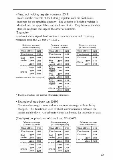
• Read out holding register contents [03H]Reads out the contents of the holding registers with the continuousnumbers for the specified quantity. The contents of holding register isdivided into the upper 8 bits and the lower 8 bits. They become the dataitems in response message in the order of numbers.
(Example) Reads out status signal, fault contents, data link status and frequencyreference from the VS-606V7 (slave 2).
* Twice as much as the number of reference message.
• Example of loop-back test [08H]Command message is returned as a response message without beingchanged. This function is used to check communication between themaster and the slave. Any arbitrary values can be used for test codes or data.
(Example) Loop-back test of slave 1 and VS-606V7
93
Slave address
Function code
Startnumber
Quantity
CRC-16
Upper
Lower
Upper
Lower
Upper
Lower
02H
03H
00H
20H
00H
04H
45H
F0H
Slave address
Function code
Number of data*
CRC-16
Upper
Lower
Upper
Lower
Upper
Lower
Upper
Lower
Upper
Lower
02H
03H
08H
00H
65H
00H
00H
00H
00H
01H
F4H
AFH
82H
FirstholdingregisterNextholdingregisterNextholdingregister
Nextholdingregister
Slave address
Function code
Error code
CRC-16Upper
Lower
02H
83H
03H
F1H
31H
Reference message (at normal operation)
Reference message (at fault occurrence)
Response message (at normal operation)
Slave address
Function code
Startnumber
Quantity
CRC-16
Upper
Lower
Upper
Lower
Upper
Lower
01H
08H
00H
00H
A5H
37H
DAH
8DH
Slave address
Function code
Error code
CRC-16Upper
Lower
01H
89H
01H
86H
50H
Slave address
Function code
Startnumber
Quantity
CRC-16
Upper
Lower
Upper
Lower
Upper
Lower
01H
08H
00H
00H
A5H
37H
DAH
8DH
Reference message (at normal operation)
Reference message (at fault occurrence)
Response message (at normal operation)
(For error code 03H, refer to page 99.)

• Writing to several holding registers [10H]Specified data are written into the several specified holding registers fromthe specified number, respectively. Written data must be arranged in acommand message in the order of the holding register numbers: fromupper eight bits to lower eight bits.
(Example) Set forward run at frequency reference 60.0 Hz to slave 1 VS-606V7 fromthe PLC.
94
Slave address
Function code
Startnumber
Quantity
CRC-16
Upper
Lower
Upper
Lower
Upper
Lower
01H
10H
00H
01H
00H
02H
10H
08H
Slave address
Function code
CRC-16
Upper
Lower
Upper
Lower
01H
10H
00H
01H
00H
02H
04H
00H
01H
02H
58H
63H
39H
Slave address
Function code
Error code
CRC-16Upper
Lower
01H
90H
02H
CDH
C1H
Startnumber
Reference message (at normal operation)
Reference message (at fault occurrence)
Response message (at normal operation)
Quantity
Firstdata
Nextdata
Number of data*
Upper
Lower
Upper
Lower
Upper
Lower
* Sets twice as large as the actual number.

95
Data• Reference Data (available to read out / write in)
Note : Write in ”0” for unused bit. Never write in data for the reserved register.
• Simultaneous Broadcasting Data (available only for write in)
Bit signals not defined as the broadcast operation signals are used as the localstation data signals.
Register No. bit
0000H
0001H
Reserved
Reserved
0 Run command 1 : Run 0 : Stop
1 Reverse run 1 : Reverse run 0 : Forward run
2 External fault 1 : Fault (EFO)
3 Fault reset 1 : Reset command
4 Multi-function input reference 1 (Function selected by n050)
5 Multi-function input reference 2 (Function selected by n051)
6 Multi-function input reference 3 (Function selected by n052)
7 Multi-function input reference 4 (Function selected by n053)
8 Multi-function input reference 5 (Function selected by n054)
9 Multi-function input reference 6 (Function selected by n055)
A Multi-function input reference 7 (Function selected by n056)
B - F
0002H Frequency reference (unit : n152)
0Multi-function output reference 1(Effective when n057=18)
( 1 : MA ON 0 : MA OFF )
1Multi-function output reference 2(Effective when n058=18)
( 1 : P1 ON 0 : P1 OFF )
2Multi-function output reference 3(Effective when n059=18)
( 1 : P2 ON 0 : P2 OFF )
3 - F
0003H
0009H
0004H-0008H
Reserved000AH-001FH
V / f gain (1000 / 100%) Setting range : 2.0 to 200.0%
(Not used)
(Not used)
Description
4 External fault 1 : Fault (EFO)
5 Fault reset 1 : Fault reset command
Register No. bit
0001H
0002H
0 Run command 1 : Run 0 : Stop
1 Reverse run 1 : Reverse run 0 : Forward run
2 (Not used)
3 (Not used)
6 - F (Not used)
30000 / 100% fixed unit(Data is converted into 0.01 Hz inside the inverter, and fractions are rounded off.)
Description
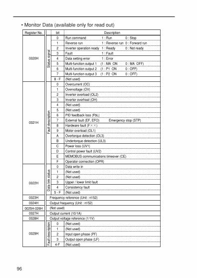
96
4 Data setting error 1 : Error
5 Multi-function output 1 (1 : MA ON 0 : MA OFF)
6 Multi-function output 2 (1 : P1 ON 0 : OFF)
7 Multi-function output 3 (1 : P2 ON 0 : OFF)
Register No. bit
0020H
0021H
Sta
tus
sign
alFa
ult d
escr
iptio
nD
ata
link
stat
us
0022H
0 Run command 1 : Run 0 : Stop
1 Reverse run 1 : Reverse run 0 : Forward run
1 : Ready
1 : Fault
0 : Not ready2 Inverter operation ready
3 Fault
8 - F (Not used)
0 Overcurrent (OC)
1 Overvoltage (OV)
2 Inverter overload (OL2)
3 Inverter overheat (OH)
4 (Not used)
5 (Not used)
6 PID feedback loss (FbL)
7 External fault (EF, EFO) Emergency stop (STP)
8 Hardware fault (F××)
9 Motor overload (OL1)
A Overtorque detection (OL3)
B Undertorque detection (UL3)
C Power loss (UV1)
D Control power fault (UV2)
E MEMOBUS communications timeover (CE)
F Operator connection (OPR)
0 Data write in
1 (Not used)
2 (Not used)
3 Upper / lower limit fault
4 Consistency fault
5 - F (Not used)
Description
0023H Frequency reference (Unit : n152)
0024H
0025H-026H0027H0028H
Output frequency (Unit : n152)(Not used)
Output current (10/1A)Output voltage reference (1/1V)
Faul
t des
crip
tion 0
1
2
3
4-F
(Not used)
(Not used)
Input open phase (PF)
Output open phase (LF)
(Not used)
0029H
• Monitor Data (available only for read out)
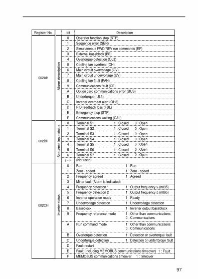
97
Register No. bit
002CH
Inve
rter s
tatu
s
0 Run
1 Zero - speed
2 Frequency agreed
3 Minor fault (Alarm is indicated)
4 Frequency detection 1
5 Frequency detection 2
6
7 Undervoltage detection
8 Baseblock
9 Frequency reference mode
A Run command mode
B Overtorque detection
C
D Fault restart
E Fault (Including MEMOBUS communications timeover)
F MEMOBUS communications timeover 1 : timeover
Description
1 : Ready
1 : Undervoltage detection
1 : Inverter output baseblock
1 : Other than communications0 : Communications
1 : Other than communications0 : Communications
1 : Detection or overtorque fault
1 : Fault
1 : Output frequency (n095)
1 : Output frequency (n095)
1 : Agreed
1 : Zero - speed
1 : Run
Inverter operation ready
Undertorque detection 1 : Detection or undertorque fault
Terminal S4 1 : Closed
Terminal S5 1 : Closed
Terminal S6 1 : Closed
1 : ClosedSeq
uenc
e in
put s
tatu
s
0 Terminal S1 1 : Closed
1 : Closed
1 : Closed
Terminal S2
Terminal S3
0 : Open
0 : Open
0 : Open0 : Open0 : Open0 : Open
6 Terminal S7(Not used)
002BH
1
2
3
4
5
7 - F
0 : Open
0
1
2
3
4
5
6
7
8
9
A
B
C
D
E
F
Operator function stop (STP)
Sequence error (SER)
Simultaneous FWD/REV run commands (EF)
External baseblock (BB)
Overtorque detection (OL3)
Cooling fan overheat (OH)
Main circuit overvoltage (OV)
Main circuit undervoltage (UV)
Cooling fan fault (FAN)
Communications fault (CE)
Option card communications error (BUS)
Undertorque (UL3)
Inverter overheat alert (OH3)
PID feedback loss (FBL)
Emergency stop (STP)
Communications waiting (CAL)
002AH
Ala
rm d
escr
iptio
n

Storing constants [ENTER command] (can be written only.)
98
RegisterNumber Name Contents Setting
Range Default
0900H ENTERcommand
Write in constant data tonon- volatile memory(EEPROM).
0000H toFFFFH ---
When a constant is written from the PLC by communications, theconstant is written to the constant data area on the RAM in the VS-606V7. ENTER command is a command to write the constant data onthe RAM to the non-volatile memory in the VS-606V7. Writing data(can be undefined) to register number 0900H during stop executes thisENTER command. Maximum number of writing times of the non-volatile memory used for
Register No. bit
002DH
002FH-0030H
003DH
Reserved
1 P1 ON”
0 CRC error
1 P1 ON”
2 P2 ON”
2 (Not used)
3 Parity error
4 Overrun error
Com
mun
icat
ions
err
or
5 Framing error
6 Timeover
7 (Not used)
0031H Main circuit DC voltage (1 / 1V)
0032H Torque monitor (1 / 1%; 100% / Motor rated torque ; with sign)
003EH-00FFH Reserved
3 - F (Not used)
Description
1 : “ON” 0 : “OFF”0 : “OFF”
0 : “OFF”1 : “ON”
1 : “ON”
”
”
0033H-0036H (Not used)
0037H Output Power (1/1W : with sign)
0038H PID feedback value (100% / Input equivalent to max. output frequency; 10 / 1%; without sign)
0039H PID input value (±100% / ± Max. output frequency ; 10/1%; with sign)
003AH PID output value (±100% / ± Max. output frequency ; 10/1%; with sign)
003BH-003CH Reserved
”
Mu
lti-fu
nctio
noutp
ut
0 MA
1: Frequency reference loss
Inve
rter
statu
s
002EH0 Frequency reference loss
1-F (Not used)
* Communications error contents are saved until fault reset is input. (Reset is enabled during run.)

Error Codes
99
01H
02H
03H
21H
22H
Error Code Contents
Function code error• Function code from PLC is other than 03H, 08H or 10H.Improper register number• No register numbers to be accessed have been registered.• ENTER command “0900H” that is an exclusive-use register for write-in was read out.Improper quantity• The number of data items to be read or write-in is not in the range between 1 and 16.• The number of data items in a message is not the value obtained by multiplying the quantity by two in the write-in mode.
Data setting error
• A simple upper/lower limit error occurred with control data or constant write-in.• A constant setting error occurred when a constant was written.
Write-in mode error• Attempt to write-in a constant from PLC was made during running.∗• Attempt to write-in an ENTER command from PLC was made during running.• Attempt to write-in a constant from PLC was made during UV occurrence.• Attempt to write-in an ENTER command from PLC was made during UV occurrence.• Attempt to write-in a constant other than n001=12, 13 (constant initialization) from PLC was made during “F04” occurrence.• Attempt to write-in a constant from PLC was made while data were being stored.• Attempt to write-in data exclusive for read-out from PLC was made.
* Refer to the constants list for constants that can be changed during operation.
VS-606V7 is 100,000; do not execute the ENTER command excessively.When a constant is changed from the digital operator, the constant dataon the RAM is written to the non-volatile memory without ENTERcommand.Register number 0900H is used only for write-in. If this register is read-out, register number error (error code: 02H) occurs.

100
Carry out the self-test in the following procedure.1. Turn ON the VS-606V7 power supply. Set constant n056 to 35 (self-test).2. Turn OFF the VS-606V7 power supply.3. Make the following wiring with the power supply turned OFF.4. Turn the power ON.
Normal operation: Operator displays frequency reference value.Faulty operation: Operator displays “CE,” fault signal is turned ON and
inverter ready signal is turned OFF.
S 7 P 1 P 2 R + R -
S 4 S C P C S + S - (Note: Select NPN side for SW1.)
Performing self-testVS-606V7 is provided with a function to perform self-diagnosis for oper-ation check of the serial communication I/F circuit. This function iscalled self-test. In the self-test, connect the sending terminal with thereceiving terminal in the communication section. It assures if the datareceived by VS-606V7 is not being changed. It also checks if the datacan be received normally.

101
Using Energy-saving Control ModeVerify that the constant n002 is set to 0 (V/f control mode) when per-forming energy-saving control. Setting n139 to 1 enables the energy-saving control function.
Energy-saving Control Selection (n139)
ConstantNo.
n139
Name
Energy-savingcontrol selection
Unit
–
SettingRange
0 : Disabled1 : Enabled
InitialSetting
0
Normally it is not necessary to change the setting. However, if themotor characteristics are different from a Yaskawa standard motor, referto the description below and change the constant setting accordingly.
• Energy-saving Control Mode (n140, n158)Calculates the voltage for the best motor efficiency when operating inenergy-saving control mode. The calculated voltage becomes the out-put voltage reference. The factory setting is set to the max. applicablemotor capacity of a Yaskawa standard motor.The greater the energy-saving coefficient is, the greater the output volt-age becomes.When using a motor other than a Yaskawa standard motor, set themotor code corresponding to the voltage and capacity to n158. Then,change the setting of the energy-saving coefficient K2 (n140) by 5% sothat the output power becomes the smallest.When the motor code is set to n158, the energy-saving coefficient K2,which corresponds to the motor code, is set to n140.
ConstantNo.
n140
n158
Name
Energy-saving control coefficient K2
Motor code
Unit
–
–
SettingRange
0.0 to 6550
0 to 70
InitialSetting
*
*
*Changes depending on inverter capacity.

102
• Energy-saving voltage lower / upper limit (n141, n142, n159, n160)Sets the upper and lower limits of the output voltage. When the valuecalculated in the energy-saving control mode is larger than the upperlimit (or smaller than the lower limit), the value is output as a voltagereference value. The upper limit is set to prevent over-excitation, andthe lower limit is set to prevent stalls when the load is light. The volt-age limit is set for machines using 6Hz/60 Hz. For any voltage otherthan 6Hz/60Hz, set the (value of the) voltage limit according to linearinterpolation. The constants are set in % for 200V/400V inverters.
ConstantNo.
n141
Name
Energy-saving control voltage lower limit (At 60 Hz)
Unit
%
SettingRange
0 to 120 50
n142Energy-saving control voltage lower limit (At 6 Hz)
% 0 to 25 12
n159Upper voltage limit for energy-saving control (At 60 Hz)
% 0 to 120 120
n160Upper voltage limit for energy-saving control (At 6 Hz)
% 0 to 25 16
InitialSetting
*Doubled for the 400V class inverters.
Voltage limit
Upper limit
Lower limit
Output frequency

103
In the energy-saving control mode, the max. applicable voltage iscalculated using the output power. However, a temperature changeor the use of another manufacturer’s motor will change the fixedconstants, and the max. applicable voltage may not be emitted. Inthe search operation, change the voltage slightly so that the max.applicable voltage can be obtained.
• Search operation Voltage Limit (n144)
Limits the range where the voltage can be controlled. The constantsare set in % for 200V/400V inverters. The search operation is notperformed when set to 0.
ConstantNo.
n144
Name
Search operationvoltage limit
Unit
% 0 to 100
SettingRange
InitialSetting
0
• Search Operation Voltage Step (n145, n146)
Sets the voltage fluctuations for one cycle of the search operation.Increase the value and the fluctuation of the rotation speed will alsoincrease. Sets the range. The value calculated by linear interpolationis set for voltage other than above.
ConstantNo.
n145
Name
Search operationvoltage step (100%)
Unit
%
SettingRange
0.1 to 10.0 0.5
n146Search operationvoltage step (5%)
% 0.1 to 10.0 0.2
n143 Power average time × 24 ms 1 to 200 1 (24 ms)
InitialSetting
Output voltage
Voltage fluctuation
Energy-saving search operation

104
• Search operation power detection hold width (n161)
When the power fluctuation is less than this value, the output voltageis held for 3 seconds. Then, the search operation mode is activated. Set the hold width in % of the power which is currently held.
ConstantNo.
n161
Name
Search operation powerdetection hold width
Unit
%
SettingRange
InitialSetting
100 to 100
• Power detection filter time constant (n162)
Response at load change is improved when this value is small.However, at low frequency, unstable rotation will result.
ConstantNo.
n162
Name
Time constant of powerdetection filter
Unit
× 4 ms
SettingRange
InitialSetting
5 (20 ms)0 to 255

105
Motor Code
The energy-saving coefficient K2 (n140) is set to a value that corre-sponds with that motor code (n158).
Motor Type
YASKAWAGeneral-purposeMotor
YASKAWAInverterMotor
Voltage Class
200V
400V
200V
400V
Capacity
0.1 kW
0.2 kW
0
1
2
3
4
5
7
21
22
23
24
25
26
27
40
41
42
43
44
45
47
61
62
63
64
65
66
67
481.7
356.9
288.2
223.7
169.4
156.8
122.9
713.8
576.4
447.4
338.8
313.6
245.8
245.8
481.7
356.9
300.9
224.7
160.4
138.9
106.9
713.8
601.8
449.4
320.8
277.8
213.8
213.8
0.4 kW
0.75 kW
1.5 kW
2.2 kW
3.7 kW
0.2 kW
0.4 kW
0.75 kW
1.5 kW
2.2 kW
3.0 kW
3.7 kW
0.1 kW
0.2 kW
0.4 kW
0.75 kW
1.5 kW
2.2 kW
3.7 kW
0.2 kW
0.4 kW
0.75 kW
1.5 kW
2.2 kW
3.0 kW
3.7 kW
Motor Code: n158Energy-saving
coefficient K2: n140

Using PID Control ModeFor details of the PID control setting, refer to the block diagram of theInverter’s internal PID control or the block diagram of the operator ana-log speed reference.
PID Control Selection: n128
ConstantNo.
n128
Name
PID control selection
Unit
–
SettingRange
0 to 8
InitialSetting
0
Setting Function PID output Characteristics
0 Disabled.
Enabled: deviation is subject to differential control.
Enabled: feedback signal is subject to differetial control.
Enabled: frequency reference + PID control, and deviation are subject to differential control.
Enabled: frequency reference + PID control, and feedback signal are subject to differential control.
1
2
3
4
5
6
7
8
Reverse
Forward
―
Set one of the above values when using PID control.The following table shows how to determine the target value and thefeedback value to be input when the PID control is enabled.
TargetValue
FeedbackValue
Input
The currently selectedfrequency reference
The frequency referencethat is set to the PID feedback value selection(n164)
Condition
Determined by the frequency reference selection(n004).When the local mode is selected, the target value isdetermined by frequency reference selection in localmode (n008).When the multi-step speed reference is selected, the currently selected frequency reference becomesthe target value.
–
n164 setting
012345
Description
Control circuit terminal FR (Voltage 0 to 10V)Control circuit terminal (Current 4 to 20 mA)Control circuit terminal (Current 0 to 20 mA)Operator terminal (Voltage 0 to 10V)Operator terminal (Current 4 to 20 mA)Pulse train
106

107
Notes: 1.When selecting frequency reference from the control circuit terminal FR as thetarget or feedback value, the V-I switch of SW2 on the control circuit board mustbe selected depending on the input method (current or voltage input).
2.Never use the frequency reference from the control circuit terminal FR for boththe target and feedback values. The frequency reference for both the target valueand the feedback value becomes the same.
(Example) When the frequency reference from the control circuit terminal FR, with a voltageof 0 to 10 V, is selected as the target value and n004=2, and when at the sametime the frequency reference from the control circuit terminal FR, with a currentof 4 to 20mA, is selected as the feedback value and n164=1, the feedback valuewill be set as the frequency reference from the control circuit terminal FR.
3.When using the analog signal(0 to 10V / 4 to 20mA) which inputs to the CN2 ter-minal of the digital operator JVOP-140 as the target or feedback value of PIDcontrol, never use it as a multi-analog input. Constant n077(multi-function ana-log input) should be set to 0 (disabled).
• Proportional gain (P), Integral time (I), Differential time (D) (n130,n131, n132)Adjust the response of the PID control with the proportional gain (P),integral time (I), and differential time (D).
ConstantNo.
n130
Name
Proportional gain (P)
Unit
Multiples
SettingRange
0.0 to 25.0
InitialSetting
1.0
n131 Integral Time (I) 1.0 s 0.0 to 360.0 1.0
n132 Differential Time (D) 1.0 s 0.00 to 2.50 0.00
Optimize the responsiveness by adjusting it while operating an actualload(mechanical system). Any control (P, I, or D) that is set to zero (0.0,0.00) will not operate.

108
ConstantNo.
n134
Name
Upper limit of integral values
Unit
%
SettingRange
0 to 100
InitialSetting
100
This constant prevents the calculated value of the integral control fromexceeding the fixed amount.There is normally no need to change the set-ting. Reduce the setting if there is a risk of load damage, or of the motor goingout of step by the inverter’s response when the load suddenly changes. Ifthe setting is reduced too much, the target value and the feedback valuewill not match.Set this constant as a percentage of the maximum output frequency withthe maximum frequency as 100%.
• Integral (I) Limit (n134)
• PID Offset Adjustment (n133)
ConstantNo.
n133
Name
PID Offset adjustment
Unit
%
SettingRange
-100 to 100
InitialSetting
0
Constant n133 adjusts the PID control offset.If both the target value and the feedback values are set to zero, adjust theinverter output frequency to zero.
• PID Primary Delay Time Constant (n135)
ConstantNo.
n135
Name
Primary delay time constantof PID output
Unit
0.1 s
SettingRange
0.0 to 10.0
InitialSetting
0.0
Constant n135 is the low-pass filter setting for PID control outputs.There is normally no need to change the setting. If the viscous friction of the mechanical system is high or if the rigidity islow causing the mechanical system to resonate, increase the setting sothat it is higher than the resonance frequency period.

109
• PID Feedback Loss Detection (n136, n137, n138)
ConstantNo.
n137
Name
PID feedback lossdetection level
Unit
%
SettingRange
0 to 100100% / Max. output frequency
InitialSetting
0
n136Selection of PIDfeedback lossdetection
– 0
n138PID feedback lossdetection time
% 0.0 to 25.5 1.0
0 : No detection of PID feedback loss1 : Detection of PID feedbak loss (Operation continued: FbL alarm)2 : Detection of PID feedback loss (Output shut down: fault)
• PID LimitSets the limit after PID control as a percentage of the maximum outputfrequency.
• Prohibition of PID outputZero limit occurs when the PID output is negative.
• PID Output Gain (n163)
ConstantNo.
n163
Name
PID output gain
Unit
Multiples
SettingRange
0.0 to 25.0
InitialSetting
1.0
This constant adjusts the output gain.
• PID Feedback Value Adjusting Gain (n129)
ConstantNo.
n129
Name
PID feedback gain
Unit
Multiples
SettingRange
0.00 to 10.00
InitialSetting
1.00
Constant n129 is the gain that adjusts the feedback value.

110
Ope
rato
r po
tent
iom
eter
FRE
F1(n
024)
Exte
rnal
term
inal
(0 to
10V
)
Exte
rnal
term
inal
( 4 to
20
mA)
Exte
rnal
term
inal
(0 to
20
mA)
Pul
se t
rain
Com
mun
icat
ion
Ope
rato
r (0
to 1
0 V)
Ope
rato
r (4
to 2
0mA)
FREF
1 (n
024) FR
EF2
(n02
5)FR
EF3
(n02
6)FR
EF4
(n02
7)FR
EF5
(n02
8)FR
EF6
(n02
9)FR
EF7
(n03
0)FR
EF8
(n03
1)FR
EF9
(n12
0)FR
EF10
(n12
1)FR
EF11
(n12
2)FR
EF12
(n12
3)FR
EF13
(n12
4)FR
EF14
(n12
5)FR
EF15
(n12
6)FR
EF16
(n12
7)
FJO
G (n
032)
n00
4Fr
eque
ncy
refe
renc
e se
lect
ion
Rem
ote/
Loca
l
Mul
ti-st
ep s
peed
refe
renc
e
Ope
rato
r pot
entio
met
er
Exte
rnal
term
inal
(0 to
10V
)
Exte
rnal
term
inal
(4 to
20
mA)
Exte
rnal
term
inal (0
to 2
0 m
A)
Ope
rato
r (0 to
10
V)
Ope
rato
r (4 to
20m
A)
Pul
se t
rain
Adj
ustm
ent
gain
Diff
eren
tial t
ime
(D)
PID
con
trol
se
lect
ion
Feed
back
val
ue
Diff
eren
tial
time
PID
con
trol
sel
ectio
n
Inte
gral
lim
it fro
m
mul
ti-fu
nctio
n in
put
Inte
gral
lim
it fr
om
mul
ti-fu
nctio
n in
put
Inte
gral
upp
er
limit
Inre
gral
time(
I)co
mpe
nsat
ion
with
rem
inde
r
Pro
port
iona
l ga
in
PID
prim
ary
dela
y tim
e co
nsta
nt c
ompe
nsat
ion
with
rem
inde
r
PID
con
trol
sel
ectio
n
PID
offs
et a
djus
tmen
t
PID
out
put g
ain
n128
=0 o
r P
ID c
ance
l by
the
mul
ti-fu
nctio
n in
put
n128
=1,2
,5.6
PID
co
ntro
l sel
ectio
n
Out
put f
requ
ency
PID
out
put
valu
eM
NT
R(U
-18)
100%
/FM
AX
PID
Con
trol
Blo
ck D
iagr
am
n164
INP
UT
Not
es: Z
-1 c
anno
t be
clea
red
durin
g op
erat
ion
com
man
d in
put.
Z-1
c
an b
e cl
eare
d du
ring
sto
p co
mm
and
inpu
t, o
r du
ring
PID
c
ance
l by
the
mul
ti-fu
nctio
n in
put.

111
Dig
ital o
pera
tor
(JV
OP
-140
)
A/D
co
nver
sion
RS
232C
ME
MO
BU
S c
omm
unic
atio
n
RS
232C
ME
MO
BU
S c
omm
unic
atio
n
A/D
co
nver
sion
A/D
con
verte
r GN
D
Max
. out
put f
requ
ency
Con
verts
A/D
(val
ue) i
nto
Hz
Prim
ary
dela
y tim
e co
nsta
nt
With
com
pens
atio
nB
ias
Gai
n
Max
. out
put f
requ
ency
Max
. out
put f
requ
ency
Gai
n
Bia
sC
ompe
nsat
ion
with
re
min
der
Prim
ary
dela
y tim
e co
nsta
ntC
onve
rts A
/D (v
alue
) int
o H
z
Max
. out
put f
requ
ency
Inve
rter
Ope
rato
r A
nalo
g S
peed
Ref
eren
ce B
lock
Dia
gram

112
Using Constant Copy Function
The VS-606V7 standard digital operator JVOP-140 can store constants forone inverter. A backup power supply is not necessary since EEPROM isused. Constant copy function is possible only for the inverters with same productseries, power supply specifications and control mode (V/f control or vectorcontrol). However, some constants may not be copied. It is also impossibleto copy constants between VS-606V7 and VSmini J7 inverters.
If any alarm occurs during constant copy, the PRGM will blink and copyingwill continue.
• Constant copy function selection (n176)Depending on the setting of n176 for constant copy function selection, thefollowing functions are available:
(1) Read all the constants from the inverter (READ) and store them inEEPROM in the digital operator.
(2) Copies the constants stored in the digital operator to the inverter (COPY).
(3) Verify that the constants in the digital operator and the constants intheinverter are the same(VERIFY).
(4) Displays the maximum applicable motor capacity and the voltage classof the inverter that has the constants stored in the digital operator.
(5) Displays the software number of the inverter that has the constantsstored in the digital operator.
Constant copy function
The prohibition of the reading of constants from the inverter can be set atn177. The constant data cannot be changed when this constant is set.

113
Constant No.
n176
Name Unit Setting Range Initial Setting
Constant copy function selection
-
rdy: READYrEd: READCPy: COPYvFy: VERIFYvA: Inverter capacity displaySno: Software No. display
rdy
Constant No.
n177
Name Unit Setting Range Initial Setting
Constant read selectionprohibit
1 00: READ prohibited
1: READ allowed
• Prohibiting constant read selection (n177) Select this function to prevent accidentally overwriting the constants
stored in EEPROM or in the digital operator. Reading is not possible when this constant is set to 0.
The constant data stored in the digital operator are safe from accidental overwriting.
When reading is performed while this constant is set to 0, PrE will blink. Press the DSPL or ENTER and return to the constant No.display.

114
Reads out the constants in batch from the inverter and stores them inEEPROM inside the digital operator. When the read-out is executed, thepreviously stored constants data in the EEPROM are cleared and replacedwith the newly entered constants.
Explanation Operator display
[Example] Store the constants read out from the inverter, in the EEPROM inside the digital operator.
• Enable the setting of the constants n001 to n179.
• Set contant read prohibited selection (n177) to READ enabled. ∗1
• Execute read-out (READ) by constant copy Function selection (n176).
• Set Constant read prohibited selection (n177) to READ disabled. ∗2
• Press DSPL to light [PRGM].
• Press ENTER to display the set value.• Change the set value to 4 by pressing or key. • Press ENTER.
• Change the constant No. to n177 by pressing or key.
• Press ENTER to display the set value.• Change the set value to 1 by pressing or key.• Press ENTER.
• Change the constant No. by pressing or key.• Press ENTER to display the set value.• Change the set value to rEd by pressing or key.• Press ENTER.
• Press DSPL or ENTER
• Change the constant No.to N177 by pressing or key.
• Press ENTER to display the set value.• Chage the set value to 0 by pressing or key.• Press ENTER.
001(Can be a different constant No.)1 ( Lit )(Can be a different set value.)4 (Blinks)
4 (Lit for one second.)↓N001 (The constant is displayd.)
N177
0 (Lit)
1 (Blinks)
1 (Lit for one second)↓N177 (The constant displayed.)
N176
ED (Lit)
ED (Lit)
ED (Blinks while executing READ)↓END (End is displayed after the execution of READ is completed.)N176 (The constant is displayed.)
N177
1 (Lit)
0 (Blinks)
0 (Lit for one second)↓N177 (the constant No. is displayed.)
∗1 When READ is enabled (n177=1), this setting is not necessary.∗2 The setting is not necessary unless the READ prohibition is selected.
v v
v v
v vv v
v v
v v
v v
READ function

Writes the constants stored inside the digital operator in batch to theinverter. Write-in is possible only for the inverters with same product series,power supply specifications and control mode (V/f control or vectorcontrol).Therefore, writing from 200 V class to 400 V class (or vice versa), from V/fcontrol mode to vector control mode (or vice versa), and from VS-606V7 toVSmini J7 are not possible.
Constant Copy Function Selection (n176), Constant Read Selection Prohibit(n177), Fault history (n178), Software version No. (n179), and hold outputfrequency is not written vAE will appear (blinking) when the capacity of theinverters differs.Press ENTER to continue writing in (the COPY function).Press STOP/RESET to stop the COPY function.Following constants are not written if the inverter capacity is different.
Constants added with software version upgrades will not be written betweenVS-606V7 Inverters without the additional constants and VS-606V7Inverters with the additional constants. For this reason, the settings for the additional constants will not be changedby the copy operation.
115
Constant No. Name Constant No. Name
n011 to n017 V/ f setting n108 Motor leakage inductance
n080 Carrier frequency selection n110 Motor no-load current
n106 Motor rated slip n158 Motor code
n036 Motor rated current n109 Torque compensation voltage limiter
n105 Torque compensation iron loss
n107 Line to neutral (per phase)
n140 Energy-saving coefficient K2
COPY function

A setting range check and matching check for the written-in constants areexecuted after the constants are written from the digital operator to theinverter. If any constant error is found, the written constants are discardedand the constants stored before writing are restored.When a setting range error is found, the constant No. where an error occursis indicated by blinking.When a matching error is found, OP ? (?:a number) is indicated byblinking.
116
Explanation Operator display• Enable the settings for the constants n001 to n179.
• Execute write-in (COPY) by Constant Copy Function Selection (n176).
• Press DSPL to light [PRGM] • Press ENTER to display the set value.• Change the set value to 4 by pressing or key.• Press ENTER.
• Change the constant No. to n176 by pressing or key.• Press ENTER to display the set value.• Change the set value to CPy by pressing or key.• Press ENTER.
• Perss DSPL or ENTER.
N001(Can be a different constant No.)1 (Lit)(Can be a different set value.)4 (Blinks)
4 (Lit for one second)↓N001 (The constant No. is displayed)N176
DY (Lit)
CPY (Lit)
CPY (Blinks while executing CPY)
↓END (End is displayed when the execution of CPY is completed.)N176 (The constant No. is displayed)
[ Example ] Write the constants from EEROM inside the degital operator to the inverter
v v
v v
v v

Collates the constants stored in the digital operator with the constant in theinverter. As well as write-in, VERIFY is possible only for the inverters withsame product series, power supply specifications and control mode (V/fcontrol or vector control).When the constants stored in the digital operator correspond to those in theinverter, vFy is displayed by blinking, then End is displayed.
Constants added with software version upgrades will be displayed whenVERIFY is performed for VS-606V7 Inverters without the additionalconstants and VS-606V7 Inverters with the additional constants.The constants added with each software version upgrade are shown in thefollowing table.
[Example] Collate the constants stored in EEPROM inside the digitaloperator with the constants in the inverter
117
VERIFY function
Software No. Additional ConstantsVSP010015
VSP010020
n175
n077, n078, n079, n115, n116
VSP010024 n040, n041, n042, n043, n044, n064, n101, n102, n117, n118, n119, n166, n167, n168, n169, n173, n174
Refer to page 160 (Constants List) for details.
Explanation Operator display
• Enable the setting for the constans n001 to n179.
• Execute VERIFY by Constant Copy Function selection (n176).
• Press DSPL to light [PRGM].• Press ENTER to display the set value.• Change the set value to 4 by Pressing or key.• Press ENTER.
• Change the constant No. to n176 by pressing or key.• Press ENTER to display the set value.• Change the set value to vFy by pressing or key.• Press ENTER.
N001(Can be a different constant No.)
1 (Lit)(Can be a different constant No.)4(Bl inks)
4(Lit for one second)↓N001 (The constant No. is displayed)
N176
DY (Lit)
VFY (Lit)
VFY (Blinks while executing VERIFY)
v v
v v
v v

The voltage class and maximum applicable motor capacity (whose constantsstored in the digital operetor are read out) are displayed.
[Example] Display the voltage class and maximum applicable motor capacity forthe inverter whose constants stored in EEPROM inside the digital operator
118
Explanation Operator display• Enable the setting for the constans n001 to n179.
• Execute Inverter Capacity Display (vA) by Constant copy function selection (n176)
• Press DSPL to light [PRGM].• Press ENTER to display the set value.• Change the set value to 4 by Pressing or key.• Press ENTER.
• Change the constant No. to n176 by pressing or key.• Press ENTER to display the set value.
• Change the set value to vA fy by pressing or key.• Press ENTER.• Press DSPL or ENTER.
N001(Can be a different constant No.)
1 (Lit)(Can be a different constant No.)4 (Bl inks)
4 (Lit for one second)↓N001 (The constant No. is displayed)
N176
DY (Lit)
VR (Lit)
20.7 (Lit) (For 20P7) ∗N176 (The constant No. is displayed)
v v
v v
v v
Inverter Capacity Display
Explanation Operator display
• Display the unmatched constant No.
• Display the constant value in the inverter.
• Display the constant value in the digital operator.
• Continue the execution of VERIFY.
• Press ENTER.
• Press ENTER.
• Press key.
• Press DSPL or ENTER.
N01 1 (Blinks) (When n011 is unmatched)
60.0 (Blinks)
50.0 (Blinks)
VFY (Blinks while executing VERIFY)↓END(End is displayed when the execution of VERIFY is completed).N176(The constant No. is displayed)
v
While an unmatched constant No. is displayed or a constant value is displayed,pressing STOP/RESET interrupts the execution of VERIFY and End is displayed.Pressing DSPL or ENTER returns to the constant No.

The software No. (of the inverter whose constants stored in the digitaloperator are read out) is displayed.
119
Explanation Operator display• Enable the setting for the constans n001 to n179.
• Execute Inverter Capacity Display (vA) by Constant copy function selection (n176)
• Press DSPL to light [PRGM].• Press ENTER to display the set value.• Change the set value to 4 by Pressing or key.• Press ENTER.
• Change the constant No. to n176 by pressing or key.• Press ENTER to display the set value.
• Change the set value to vA fy by pressing or key.• Press ENTER.• Press DSPL or ENTER.
N001(Can be a different constant No.)
1 (Lit)(Can be a different constant No.)4 (Bl inks)
4 (Lit for one second)↓N001 (The constant No. is displayed)
N176
DY (Lit)
VR (Lit)
20.7 (Lit) (For 20P7) ∗N176 (The constant No. is displayed)
v v
v v
v v
Explanation Operator display• Enable the setting for the constans n001 to n179.
• Execute Software No. Display (Sno)∗ by Constant copy function selection (n176).
• Press DSPL to light [PRGM].• Press ENTER to display the set value.• Change the set value to 4 by Pressing or key.• Press ENTER.
• Change the constant No. to n176 by pressing or key.• Press ENTER to display the set value.• Change the set value to Sno by pressing or key.• Press ENTER.
• Press DSPL or ENTER.
N001(Can be a different constant No.)
1 (Lit)(Can be a different set value.)4 (Bl inks)
4 (Lit for one second)↓N001 (The constant No. is displayed)
N176
DY (Lit)
SNO (Lit)
0013 (Lit) (software version : VSP010013)N176 (The constant No. is displayed)
∗ Displays Lower 4 digits of the software version.
[Example] Display the software No. of the inverter whose constants stored in EEPROM inside the digital operator
v v
v v
v v
Software No. Display

120
Operatordisplay
DY
ED
CPY
VFY
SNO
END
P E
DE
CSE
DPS
CPE
CYE
F04
VRE
FE
Description Corrective action
Lit: Setting for constant copy functionselection enabled
Lit: READ selected Blinks: READ under execution
Lit: Writing (COPY) selected Blinks: Writing (COPY) under execution
Lit: VERIFY selectedBlinks: VERIFY under execution
Lit: Inverter capacity display selected
Lit: Software No. Display selected
Lit: READ, COPY (writing), or VERIFY completed
Blinks: Attempt to execute READ while constant read selection prohibit (n177) is set to 0.
Confirm the necessity to execute READ, thenset constant read selection prohibit (n177)to 1 to execute READ.
Confirm that the main circuit power supplyvoltage is correct, then re-execute READ.
The constans stored in the digital operatorcannot be used.Re-execute READ to store the constans in the digital operator.
Check if they are the same product series.
Execute READ.
Confirm that the main circuit power supplyvoltage is correct, then re-execute writing(COPY).Initialize the constans. If an error occursagain, replace the inverter due to a failureof constant memory element (EEPROM)in the inverter.Press ENTER to continue the execution ofCOPY or VERIFY. Press STOP to interrupt the execution of COPY or VERIFY.
Check the connection between the inverter and the digital operator.If a communication error occurs durring READoperation or writing (COPY) operation, be sureto re-execute READ or COPY.
Check each voltage class and control mode.
Blinks: The constant could not be read properly by READ operation. Or, a main circuit low voltage is detected during READ operation.
Blinks: A sumcheck error occurs in the consant data stored in the digital operator.
Blinks: The password for the connected inverter and that for the constant data stored in the digital operator are disagreed. [Ex.] Writing (COPY) from VS-606V7 to VSmini J7
Blinks: No constant data stored in the digital operator.
Blinks: Attempt to execute writing (COPY) orVERIFY between different voltage classes ordifferent control modes.
Blinks: A main circuit low voltage is detected during writing (COPY) operation.
Lit: A sumcheck error occurs in the constantdata stored in the inverter.
Blinks: Attempt to execute COPY or VERIFY between different inverters of different capacities.
Blinks: A communication error occurs between the inverter and the digital operator.
-
-
-
-
-
-
-
Note: While rEd, CPy, or vFy is displayed by blinking, key input on the digital operator is disabled. While rEd, CPy and vFy are not displayed by blinking, pressing DSPL or ENTER redisplays the constant No.
Display List
VR

121
Unit selection for Frequency Reference Setting/Display Constants and monitor display for which selection of unit function is valid
Item Contents
Frequency reference constants
Frequency reference 1 to 8 (Constants n024 to n031)
Jog frequency reference (Constant n032)
Frequency reference 9 to 16 (Constants n120 to n127)
Frequency reference display (FREF)
Output frequency display (FOUT)
Frequency reference display (U-01)
Output frequency display (U-02)
Monitor display
• Function Outline The frequency reference, output frequency and the numerical data of frequency reference constant can be displayed in %, r/min, m/min according to the set value of constant n035.Constant
No.
Setting
0
•Setting unit: 0.01 Hz (less than 100 Hz), 0.1 Hz (100 Hz and more) •Setting range minFmax (n011) Frequency reference lower limit (n034) to Fmax (n011) Frequency reference upper limit (n033), 400 Hz
•Setting in units of 0.1 % : 100.0 % / Fmax (n011) •Setting range minFrequency reference lower limit (n034) to Frequency reference upper limit (n033), (400Hz Fmax (n011) 100 %
•Setting in units of 1 r/min: r/min=120 Frequency reference (Hz) n035 (Set the number of motor poles for n035) •Setting range min120 (Fmax (n011) Frequency reference lower limit (n034) n035~120 (Fmax(n011)Frequency reference upper limit (n033)) n035, 400Hzx120 P, 9999r/min
1
2 to 39
Description
Constant Name Description Initialsetting
0035
Selecting sett ing/displaying unit of frequency reference
0: in units of 0.01 Hz (less than 100 Hz) 0.1Hz (100 Hz and more)1: in units of r/min (set the number of motor poles) 40 to 3999: in any unit
• n035 setting
•Set the display value at 100 % of frequency reference (set value of Fmax (n011)) at 1 of n035.

122
Constantn035
Setting
40to
3999
Description
0123
(Example) To display 20.0 at 100 % of frequency reference, set n035 to “1200.”
• Setting range min(Lower 3-digits of n035) Frequency reference lower limit (n034) to (Lower 3-d igits of n035) Frequency reference upper limit (n033), 400Hz (Lower 3-digits of n035) Fmax(n011), 999 Max. upper limit value: (Set value (Lower 3-digits of n035)) Fmax(n011) 400 Hz
Notes:1. The frequency reference constants and monitor display data for which this selection of unit function is valid, are stored in the inverter in units of Hz. The units are converted as follows.
Setting/Display Constant n035 Frequency reference constants Data for monitor display
2. The upper limit for each unit is the figure whose fractions below the significant digits are cut off. (Example) Where the upper limit value for the unit Hz is 60.00 Hz and n035 = 39, 120 60.00 Hz 39 = 184.9, accordingly 184 r/min is displayed for the upper limit value.
For the displays other than upper limit value, the fractions below the significant digits are rounded.
3. To execute VERIFY for constant COPY function, frequency reference constants (in units of Hz) is applied.
Each unitsystem Units of Hz
Display
Setting
0.
By a number of 4th digit of n035, set the position of decimal point. By 1st to 4th digit of n035, set a 3-digits figure excluding decimal point. Number of 4th digit. Position of decimal point40 to 3999
• Set the display value at 100% of frequency reference (set value of Fmax(n011)) at 1st to 4th digit of n035.
..
≤−

Selecting Processing for Frequency ReferenceLoss (n064)
Use this setting to select the processing performed if the level of thefrequency reference signal from the control circuit terminals suddenly drops.
* Detected in REMOTE mode (drive mode) when analog reference (except potentiometer on
digital operator) or pulse train reference is selected in the frequency reference selection (n004).
Processing Method When 1 is SelectedIf the level of the frequency reference signal drops by 90% within 400ms,operation continues at 80% of the signal level before the level drop.
123
Constant n064 Setting Description
0
1*
Processing for frequency reference loss disabled.
Processing for frequency reference loss enabled.

124
Input/Output Open-phase Detection
* 1 Not detected when set to 0%.
* 2 Not detected when set to 0.0 s.
The recommended settings for input open-phase detection are n166 = 7%and n167 = 10 s.
The recommended settings for input open-phase detection are n168 = 5%and n169 = 0.2 s.
Constant No. Name Setting Range Initial Setting
n166
Input Open-phase Detection Level
Setting unit: 1%Setting range: 0 to 100%*1
400.0 V/100% (200 V Class)800.0 V/100% (400 V Class)
0%
n167
Input Open-phase Detection Time
Setting unit: 1 sSetting range: 0 to 255 s*2
0 s
n168
Output Open-phase Detection Level
Setting unit: 1%Setting range: 0 to 100%*1
Inverter's rated output current/100%
0%
n169
Output Open-phase Detection Time
Setting unit: 0.1 sSetting range: 0.0 to 2.0 s*2
0.0 s
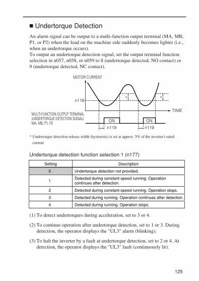
125
Undertorque Detection
An alarm signal can be output to a multi-function output terminal (MA, MB,P1, or P2) when the load on the machine side suddenly becomes lighter (i.e.,when an undertorque occurs).To output an undertorque detection signal, set the output terminal functionselection in n057, n058, or n059 to 8 (undertorque detected, NO contact) or9 (undertorque detected, NC contact).
* Undertorque detection release width (hysteresis) is set at approx. 5% of the inverter's rated
current.
Undertorque detection function selection 1 (n177)
(1) To detect undertorques during acceleration, set to 3 or 4.
(2) To continue operation after undertorque detection, set to 1 or 3. Duringdetection, the operator displays the "UL3" alarm (blinking).
(3) To halt the inverter by a fault at undertorque detection, set to 2 or 4. Atdetection, the operator displays the "UL3" fault (continuously lit).
TIME
n119n119
ONON
MOTOR CURRENT
n118
MULTI-FUNCTION OUTPUT TERMINAL(UNDERTORQUE DETECTION SIGNAL)MA, MB, P1, P2
* *
Setting Description
0
1
Undertorque detection not provided.
Detected during constant-speed running. Operation continues after detection.
2 Detected during constant-speed running. Operation stops.
3 Detected during running. Operation continues after detection.
4 Detected during running. Operation stops.

126
Underorque detection level (n118)Sets the undertorque detection current level in units of 1%. (Inverter ratedcurrent = 100%) when detected by torque is selected, motor rated torquebecomes 100%.Initial setting = 10%
Undertorque detection time (n119)If the time for which the motor current is less than the undertorque detectionlevel (n118) is longer than the undertorque detection time (n119), theundertorque detection function operates.Initial setting = 0.1 s
Overtorque/Undertorque detection function selection 2 (n097)When vector control mode is selected, it is possible to select whetherovertorque/undertorque detection is performed by output current or outputtorque.When V/f control mode is selected, the n097 setting becomes invalid, andovertorque/undertorque is detected by output current.
Setting Description
0 Overtorque/undertorque detected by output torque.
Overtorque/undertorque detected by output current.1

127
Using Inverters for Elevating Machines
When using the VS-606V7 for elevating machines such as elevators andcranes, make sure that the brake holds and observe the followingprecautions for safe operation.
Brake ON/OFF Sequence
• For the holding brake's ON/OFF sequence, use the following inverteroutput signals according to the set control mode.
Do not use "Running (Set value: 1)" for the holding brake's ON/OFFinterlock signal.
Notes: 1. For Vector control (n002=1), use the same brake ON/OFF sequence with thesame signals as for V/F control.
2. Shows the setting when a multi-function photocoupler output terminal (P1-PC) isused.
3. Usually, make the following settings for the frequency detection (n095):For V/f control: Motor rated slip frequency + 1 HzFor Vector control: 2.5 Hz to 3.0 Hz
If the set value is too low, the motor torque is insufficient and the load may shiftwhen the brake is applied. Be sure to set n095 to a value larger than that of theminimum output frequency (n016)and larger than that of the brake releasingwidth shown in the following figure. If the set value is too large, the motor maynot run smoothly when it starts running.
NOTE
Control Mode
Brake ON/OFF Signal Brake ON/OFF Level Adjustment
V/f Control (Note 1)
(n002=0)Frequencydetection 1 n058=4
Frequency detection level
n095=2.50 Hz to 4.00 Hz (Note 3)
Signal Name Constant (Note 2) ConstantSignal Name
Output freqency n095
Freqency detection level 1Time
Releasing width -2Hz
ON OFF

128
• Sequence Circuit Configuration and Timing Chart Examples
For the AC sequence circuit,connect the signal between P1 andPC to the sequence circuit with arelay.Design the sequence so that thehoiding brake contact is openwhen the sequense operationconditions are satisfied and thecontact between P1 and PC isclosed(ON).Make sure that the holding brakecontact is closed when theemergency stop signal or inverterfault contact output signal is ON.
• For V/f Control and Vector Control
• For a variable speed operation by an analog signal, set the frequency reference selection
(n004) to a value from 2 to 4.
Frequencydetection 1
INVERTER VS-606V7
(Forward run)
(Reverse run)
(Multi-step speed reference 2)
Sequencecircuit
Energizes the brake when ON(30 VDC 1 A or less)
Holding brakeauxiliary relay coil +24V
MAUP
DOWN
HIGH/LOW
BRMB
MC
SC
S6
S2
S1
P1
PC
Fault contacts
Input
Output
Output Frequency0
Frequencydetection 1(n058=4)Holding brakeoperation
TimeDC injection brake
High speed/Low speed
UPS1 – SC
S6 – SC
P1 – PC
ONOFF
ON
ON
OPENCLOSE CLOSE
OFF
n095n095
OFF
n026n024 (Enabled when n004=1)

129
Stall Prevention During DecelerationIf connecting a braking resistor to discharge regenerative energy, be sureto set the stall prevention during deceleration (n092) to 1.
If the stall prevention during deceleration (n092) is set to the initialvalue 0 (Enabled), the motor may not stop within the specifieddecelerating time.The stall prevention during acceleration (n093) and the stallprevention level during running (n094) should be set to their initialvalues to enable these functions.
Settings for V/f Pattern and Motor Constants To set the control mode and the V/f pattern, refer to the instructionmanual and the document "Motor Constant Settings for VS-606V7Vector Control (Document No. F-07-V7-01)". If the Vector controlmethod is used, also set the motor constants.
Momentary Power Loss Restart and Fault Restart Do not use the momentary power loss restart and fault restart functionsin applications for elevating machines. Make sure that n081=0 andn082=0. If these functions are used, the motor coasts to a stop with thebrake contact open when a momentary power loss or fault occurs duringoperation, possibly resulting in serious accidents.
I/O Open-phase Protection and Overtorque Detection The I/O open-phase protection is only available for 5.5 kW and 7.5 kWmodels. To prevent the machine from falling when the motor is open-phase orsimilar situation, enable the I/O open-phase protection (n166 to n169)and the overtorque detection (n096 to n099). At the factory, theseconstants are set so that these functions are disabled.Also, take safety measures such as protection against falls on themachine.
Carrier FrequencySet the carrier frequency selection (n080) to 5 Hz or more (n080 : 2 to 4)to secure the motor torque even if an overcurrent occurs (the current islimited).
NOTE

130
External Baseblock SignalIf the external baseblock command (settings 12 and 13 of n050 to n056)is input while the motor is running, the motor will immediately coast to astop. Do not input the external baseblock command while the motor isrunning unless necessary.If using the external baseblock command for an emergency stop or to runstart an interlock, make sure that the holding brake operates.If the external baseblock command is input and immediately reset, theinverter does not output voltage during the minimum baseblock time,which is 0.5 to 0.7 seconds depending on the inverter capacity. Do notuse the external baseblock command in an application where the motor isfrequently started and stopped.
Acceleration/Deceleration TimeIf the delay time for the holding brake's mechanical operation is nottaken into consideration and the acceleration/deceleration time on theinverter side is set to a time that is too short , an overcurrent or wear onthe brakes may occur at starting or the load will shift at stopping becausethe holding brake does not operate on time. If so, use the S-curvecharacteristic function or lengthen the acceleration/deceleration time totune the timing for the holding brake.
Contactor on the Inverter's Output-side Do not install a contactor between the inverter and the motor.If a contactor must be installed because of local electrical codes orregulations or to operate motors with an inverter, excluding emergencies,open or close the contactor only when the holding brake is fully closedand the inverter is in baseblock status with the baseblock signal ON.If the contactor is opened or closed while the inverter is controlling themotor or DC injection braking, surge voltage or a current from the motorby full-voltage starting may cause an inverter fault.When a contactor is installed between the inverter and the motor, enablethe I/O open-phase protection (n166 to n169).
For more information on using Inverters exclusively for elevators or cranes,contact your Yaskawa representatives or the nearest Yaskawa sales office.

7. MAINTENANCE AND INSPECTION Periodical InspectionPeriodically inspect the inverter as described in the following table toprevent accidents and to ensure high performance with high-reliability.
Part ReplacementInverter’s maintenance periods are noted below. Keep them as reference.
131
Location to Check
Terminals, unitmounting screws,etc.
Heatsink
Connection hardware is properly seated and securely tightened.
Properly seat and tighten hardware.
Check For Solution
4 4
2
Built up dust, dirt, and debris Blow with dry compressed air :39.2 10 to 58.8 10 Pa,57 to 85 psi (4 to 6kg / cm )pressure
Cooling fan Abnormal noise or vibrationCumulative operation time exceeding 20,000 hours
Replace the cooling fan.
Replace the inverter unit.Abnormal odor or discoloration
Power elements and smoothingcapacitor
Accumulation of conductivematerial or oil mist
Printed circuitboard
Blow with dry compressed air :39.2 104 to 58.8 104 Pa,57 to 85 psi (4 to 6kg / cm2 )pressureIf dust or oil cannot beremoved, replace the inverterunit.
Part
Part Replacement GuidelinesStandard Replacement Period
Cooling fan
Smoothing capacitor
Breaker relays
FusesAluminum capacitorson PCBs
Replacement Method
Replace with new part.Replace with new part.(Determine need by inspection.)Determine need by inspection.Replace with new part.Replace with new board.(Determine need by inspection.)
2 to 3 years
5 years
----10 years
5 years
Note Usage conditions are as follows:• Ambient temperature: Yearly average of 30˚C• Load factor: 80% max.• Operating rate: 12 hours max. per day
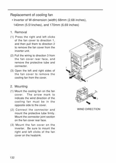
132
1. Removal
(1) Press the right and left clicksof the fan cover to direction 1,and then pull them to direction 2to remove the fan cover from theinverter unit.
(2) Pull the wiring to direction 3 fromthe fan cover rear face, andremove the protective tube andconnector.
(3) Open the left and right sides ofthe fan cover to remove thecooling fan from the cover.
2. Mounting
(1) Mount the cooling fan on the fancover. The arrow mark toindicate the wind direction of thecooling fan must be in theopposite side to the cover.
(2) Connect the connector andmount the protective tube firmly.Mount the connector joint sectionon the fan cover rear face.
(3) Mount the fan cover on theinverter. Be sure to mount theright and left clicks of the fancover on the heatsink.
Replacement of cooling fan• Inverter of W-dimension (width) 68mm (2.68 inches),
140mm (5.51inches), and 170mm (6.69 inches)
WIND DIRECTION

133
1. Removal
(1) Remove the front cover andterminal cover, and then removethe cooling fan connector(CN10).
(2) Press the right and left clicks ofthe fan cover to direction 1, andpull the fan cover to direction 2to remove it from the inverterunit. Pull out the wiring from thecable lead-in hole at the bottomof the plastic case.
(3) Open the right and left sides ofthe fan cover to remove thecover from the cooling fan.
2. Mounting
(1) Mount the cooling fan on the fancover. The arrow mark toindicate the wind direction mustbe opposite to the cover.
(2) Mount the fan cover on theinverter. Be sure to mount theright and left clicks of the fancover on the heatsink. Lead inthe wiring from the cable lead-inhole at the bottom of the plasticcase to the inside of the inverter.
(3) Connect the wiring to the coolingfan connector (CN10) and mountthe front cover and the terminalcover.
• Inverter of W-dimension (width) 108mm (4.25 inches)
COOLING FAN WIRE
WIND DIRECTION

8. FAULT DIAGNOSIS Protective and Diagnostic FunctionThis section describes the alarm and fault displays, explanations for faultconditions and corrective actions to be taken if the VS-606V7 malfunctions.
< Corrective actions for models with blank cover >
1. Input fault reset or cycle the power supply OFF and ON.
2. When a fault cannot be corrected:(1) Turn the power supply OFF and check the wiring and external circuit
(sequence) . (2) Turn the power supply OFF and replace the blank cover with the
digital operator to display faults. The faults are displayed after turningthe power ON.
134

135
<Corrective Actions of Models with Digital Operator>
Alarm Display and Contents
Alarm DisplayDigital Operator
RUN (Green)ALARM (Red)
Inverter Status Explanation Causes and
Corrective Actions
Warning
Fault contactsdo notchangestate.
200V:Main circuit DC voltage drops below approx. 200V. (160V for single- phase)400V:Main circuit DC voltage drops below approx. 400V.(Control supply fault)Control power supply faultis detected while the inverter output is OFF.
CAL (MEMOBUS communications waiting)Correct data has not been received from the PLC when the constants n003 (run command selection) is 2 or n004(frequency reference selection) is 6, and power is turned ON.
Check communication devices, and transmission signals.
OH
Blinking
CRL
Blinking
UV (Main circuit low voltage)Main circuit DC voltage drops below the low-voltage detection level while the inverter output is OFF.
OV (Main circuit overvoltage)Main circuit DC voltage exceeds the overvoltage detection level while theinverter output is OFF.Detection level200V class : approx 410V or more 400V class : approx 820V or more
OH (Cooling fin overheat)Intake air temperature rises while the inverter output is OFF.
Check the following :• Power supply voltage• Main circuit power supply wiring is connected.• Terminal screws are securely tightened.
Check the power supply voltage.
Check the intake air temperature.
U
Blinking
O
Blinking
: ON : BLINKING : OFF

136
Alarm DisplayDigital Operator
RUN (Green)ALARM (Red)
Inverter Status Explanation Causes and
Corrective Actions
Warning
Fault contacts do not change state.
OL3
Blinking
OP?
Blinking
SE
Blinking
OP? (Constant setting error when the constant setting is performed through the MEMOBUS communications)OP1: Two or more values are set for multi- function input selection. (constants n050 to n056)OP2: Relationship among V / f constants is not correct. (constants n011, n013, n014, n016)OP3: Setting value of motor rated current exceeds 150% of inverter rated current. (constant n036) OP4: Upper / lower limit of frequency reference is reversed. (constants n033, n034)OP5: (constants n083 to n085)
Check the setting values.
OL 3 (Overtorque detection)Motor current exceededthe preset value in constant n098.
Reduce the load, and expand the accel / decel time.
SER (Sequence error)Inverter receives LOCAL / REMOTE select command or communication / control circuit terminal changing signals from the multi-function terminal while the inverter is outputting.
Check the external circuit(sequence).
No faultoutput.Automaticreset aftercause removed.
UL3
UL3 (Undertorque detection)When V/f mode is selected:The inverter’s output current was less than the undertorque detection level (n118).When vector mode is selected:The output current or output torque was less than the detection level (n097 or n118).Operation when undertorque is detected will be determined by the setting in n117.
• Check the setting in n118.• Check the operating conditions, and remove the cause.

137
Alarm DisplayDigital Operator
RUN (Green)ALARM (Red)
Inverter Status Explanation Causes and
Corrective Actions
EF (Simultaneous FWD/ REV run commands)When FWD and REVrun commands are simultaneously input for over 500ms, the inverter stops according to constant n005.
BB (External baseblock)Baseblock command at multi-function terminal is active, the inverter output is shut OFF (motor coasting).Temporary condition is clearedwhen input command is removed.
STP (Operator function stop)
STOPRESET is pressed
during running by the control circuit terminalsFWD / REV command, or by the run command fromcommunicationsThe inverter stops according to constant n005.STP(Emergency stop)Inverter receives emergency stop alarm signal. Inverter stops according to constant n005.
Check the external circuit(sequence).
Check the external circuit(sequence).
Check the external circuit(sequence).
Open FWD/REV command of control circuit terminals .
FAN(Cooling fan fault)Cooling fan is locked.
Check the following: • Cooling fan • Cooling fan wiring is not connected.
CE (MEMOBUS)communications fault
FBL (PID feedback loss detection )PID feedback value dropsbelow the detection level. When PID feedback loss isdetected , the inverter operates according to the n136 setting.
Option card communicationsfault. Communication fault has occured in a mode that run command and frequency reference are set from the communication option card.
Check the communicationdevices or communicationsignals.
Check the mechanical system and correct the cause, or increase the value of n137.
Check the communicationdevices or communicationsignals.
or
Warning
Fault contacts do not change state.
OH3
No fault output.Automatic reset after causeremoved.
OH3 (Inverter overheat alarm)The inverter overheat alarm (OH3) was input from a multi-function input terminal(S1 and S7).
Clear the multi-function input terminal’s inverteroverheat alert input.
EF
Blinking
BB
Blinking
S P
Blinking
FRN
Blinking
CE
Blinking
BU5
Blinking
FBL
Blinking

Fault Display and Contents
138
Fault DisplayDigital Operator
RUN (Green)ALARM (Red)
Inverter Status Explanation Causes and
Corrective Actions
OC
OV
UV1
ProtectiveOperation
OC (Overcurrent)Inverter output current momentarily exceeds approx. 250% of rated current.
Output is shut OFFand motorcoasts to a stop.
• Short circuit or grounding at inverter output side• Excessive load GD2
• Extremely rapid accel/ decel time (constants n019 to n022)• Special motor used• Starting motor during coasting • Motor of a capacity greater than the inverter rating has been started.• Magnetic contactor open/closed at the inverter output side
OV (Main circuit over-voltage)Main circuit DC voltage exceeds the overvoltage detection level because of excessive regenerative energy from the motor.
• Insufficient decel time (constants n020 and n022)• Lowering of minus load (elevator, etc.)
• Increase decel time.• Connect optional braking resistor.
Detection level: 200V:Stops at main circuit DC voltage below approx. 410V 400V:Stops at main circuit DC voltage approx. 820V or more
UV1 (Main circuit low voltage)Main circuit DC voltagedrops below the low-voltage detection level while the inverter output is ON.
• Reduction of input power supply voltage• Open phase of input supply• Occurrence of momen- tary power loss
Check the following :• Power supply voltage• Main circuit power supply wiring is connected.• Terminal screws are securely tightened.
200V:Stops at main circuit DC voltage below approx. 200V(160V for single-phase)400V:Stops at main circuit DC voltage approx. 400V or more

139
Fault DisplayDigital Operator
RUN (Green)ALARM (Red)
Inverter Status Explanation Causes and
Corrective Actions
OH
OL1
OL2
UV2
OL3
ProtectiveOperation
OH (Cooling fin overheat)Temperature rise because of inverteroverload operation or intake air temperature rise.
Output is shut OFFand motorcoasts to a stop.
• Excessive load• Improper V/f pattern setting• Insufficient accel time if the fault occurs during acceleration• Intake air temperature exceeding 50:(122<)• Cooling fan stops
Check the following :• Load size• V/f pattern setting (constants n011 to n017)• Intake air temperature.
OL1 (Motor overload)Motor overload protection operates by built-in electronic thermaloverload relay.
• Check the load size or V/f pattern setting (constants n011 to n017)• Set the motor rated current shown on the nameplate by constant n036.
OL2 (Inverter overload)Inverter overload protection operates by built-in electronic thermaloverload relay.
• Check the load size or V/f pattern setting (constants n011 to n017)• Check the inverter capacity.
Check the driven machine and correct the cause of the fault, or increase the value ofconstant n098 up to the highest value allowed for the machine.
UV2 (Control power supply fault)Voltage fault of controlpower supply is detected.
Cycle power. If the fault remains, replace the inverter.
OL3 (Overtorque detection)V/f mode: Inverter output current exceeded the preset value in constant n098.Vector mode: Motor current or torque exceeded the preset value in constants n097 and n098.When overtorque is detected, inverter performs operation according to the preset setting of constant n096.

140
Fault DisplayDigital Operator
RUN (Green)ALARM (Red)
Inverter Status Explanation Causes and
Corrective Actions
EF? (External fault)Inverter receives an external fault input from control circuit terminal.EF?
PF
LF
UL3
EF0: External fault reference through MEMOBUS communications
LF (Output open phase)An open phase occurred in inverter output.
• Disconnection in output cable• Disconnection in motor windings• Loose output terminal screws
Check the following:• Main circuit power supply wiring is connected.• Power supply voltage• Terminal screws are securely tightened.
UL3 (Undertorque detection)When V/f mode is selected:The inverter’s output current was less than the undertorque detection level(n118).When vector mode is selected:The output current or output torque was less than the detection level(n097 or n118).Operation when undertorque is detected will be determined by the setting in n117.
• Check the setting in n118.• Check the operating conditions, and remove the cause.
Check the external circuit(sequence).
PF (Main circuit voltage fault)The main circuit’s DC voltage oscillated in an irregular way when not inregenerative operation.
• Open phase of input supply• Occurrence of momentary power loss• Excessive fluctuation in input supply voltage• Unbalanced line voltage
Check the following:• Main circuit power supply wiring is connected.• Power supply voltage• Terminal screws are securely tightened.
ProtectiveOperation
Output is shut OFFand motorcoasts to a stop.

141
Fault DisplayDigital Operator
RUN (Green)ALARM (Red)
Inverter Status Explanation Causes and
Corrective Actions
F05
F07
CPF-06• Option card connecting fault• A non-corresponding option card is connected.
Remove power to the inverter.Check the connection of the digital operator . Verify Software versionNo. (n179).
F06
CPF-05AD converter fault is detected.
Cycle power.If the fault remains, replace the inverter.
CPF-07 Operator control circuit (EEPROM or AD converter) fault
Cycle power after checking the digital operator is securely mounted. If the fault remains, replace the digital operator or inverter.
EF?
F00
F01
F04
EF1: External fault input command from control circuit terminal S1EF2: External fault input command from control circuit terminal S2EF3: External fault input command from control circuit terminal S3EF4: External fault input command from control circuit terminal S4EF5: External fault input command from control circuit terminal S5EF6: External fault input command from control circuit terminal S6EF7: External fault input command from control circuit terminal S7
CPF-00Inverter cannot communicate with the digital operator for 5 sec. or morewhen power is turned ON.
CPF-01Transmission fault occurred for 5 sec. or more when transmission starts with the digital operator.
CPF-04EEPROM fault of inverter control circuit is detected.
Cycle power after checking the digital operator is securely mounted. If the fault remains, replace the digital operator or inverter.
Cycle power after checking the digital operator is securely mounted. If the fault remains, replace the digital operator or inverter.
• Record all constant data and initialize the constants. (Refer to page 32 for constant initialization.)• Cycle power. If the fault remains, replace the inverter.
Check the external circuit(sequence).
ProtectiveOperation
Output is shut OFFand motorcoasts to a stop.
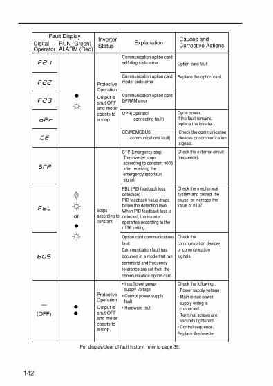
142
ProtectiveOperation
Output is shut OFFand motorcoasts to a stop.
Cycle power.If the fault remains, replace the inverter.
Option card fault
Replace the option card.
OPR(Operator connecting fault)
Communication option cardDPRAM error
Communication option cardmodel code error
Communication option cardself diagnostic error
CE(MEMOBUS communications fault)
Check the communication devices or communication signals.
STP(Emergency stop) The inverter stops according to constant n005 after receiving the emergency stop fault signal.
Check the external circuit(sequence).
orStops according to constant
—
(OFF)
• Insufficient power supply voltage• Control power supply fault• Hardware fault
Check the following :• Power supply voltage• Main circuit power supply wiring is connected.• Terminal screws are securely tightened.• Control sequence.Replace the inverter.
For display/clear of fault history, refer to page 39.
Option card communicationsfaultCommunication fault hasoccurred in a mode that run command and frequencyreference are set from the communication option card.
Check the communication devicesor communicationsignals.
InverterStatus
Fault DisplayRUN (Green)ALARM (Red)
DigitalOperator
ExplanationCauces andCorrective Actions
FBL (PID feedback lossdetection)PID feedback value dropsbelow the detection level.When PID feedback loss isdetected, the inverteroperartes according to the n136 setting.
Check the mechanicalsystem and correct the cause, or increase the value of n137.
ProtectiveOperation
Output is shut OFFand motorcoasts to a stop.

143
TroubleshootingTrouble Cause Corrective Actions
The motor does not operate when an external operation signal is input.
The operation method selection is wrong.The run command (n003) is not set to Control Circuit Terminal.
Set the run command (n003) to Control Circuit Terminal.
The motor stops. The torque is not output.
The stall prevention level during acceleration is too low.Because the stall prevention level during acceleration (n093) is set too low, the output current reaches the set level, the output frequency is stopped, and the acceleration time is lengthened.
Check if the stall prevention level during acceleration (n093) is set to an appropriate value.
A 3-wire sequence is in effect.The multi-function input method (n052) is set to 3-wire sequence,and the S2 control terminal is not closed.
To use a 3-wire sequence, make the wiring so that the S2 control terminal is closed. To use a 2-wire sequence, set the multi-function input (n052) to a value other than 3-wire sequence.
Local mode is in effect. Set the LO/RE selection of the digital operator to RE.
The SW setting for the reference selection is wrong.Example: The reference 4-20mA is input, but the SW is set to " V ".
For analog input, make sure that the frequency reference (n004) and SW settings are correct.
The stall prevention level during running is too low.Because the stall prevention level during running (n094) is set too low, the output current reaches the set level, and the speed drops.
Check if the stall prevention level during running (n094) is set to an appropriate value.
The load is too heavy.If the load is too heavy, stall prevention is activated, the output frequency is stopped, and the acceleration time is lengthened.
Lengthen the set acceleration time (n019). Reduce the load.
When the maximum frequency was changed, the maximum voltage frequency was also changed.
To increase the speed of a general-purpose motor, only change the maximum frequency.
The V/f set value is too low. Set the V/f (n011 to n017) according to the load characteristics.
The frequency reference is too low.The input frequency reference is lower than the setting for the min.output frequency (n016).
Input a frequency reference greater than the min. output frequency (n016).

144
Trouble Cause Corrective Actions
The motor speed is unstable. The motor speed fluctuates when operating with a light load.
The stall prevention level during running is too low.Because the stall prevention level during running (n094) is too low, the output current reaches the set level and the speed drops.
Check if the stall prevention level during running (n094) is set to an appropriate value.
The digital operator does not turn ON.
The power is not being supplied.The breaker or other component on the power input side is not turned ON, and the power is being not supplied.
Check if the power is being supplied.
The digital operator is not correctly mounted.Because the digital operator is not correctly mounted, the display does not appear.
Mount the digiral operator correctly.
The load is too heavy.If the load is too heavy, stall prevention is activated, the output frequency is stopped, and the acceleration time is lengthened.
Reduce the load.
The carrier frequency is too high.If operating the motor with a light load, a high carrier frequency may cause the motor speed to fluctuate.
Decrease the carrier frequency (n080).
The V/f set value is too high for a low speed operation.Because the set value for the V/f is too high, over-excitation occurs at low speeds.
Set the V/f (n011 to n017) according to the load characteristics.
The maximum frequency and base frequency were incorrectly adjusted. Example: To operate a 60 Hz motor at 40 Hz or less, the maximum frequency and base frequency are set to 40 Hz.
Set the maximum frequency and the base frequency according to the motor specifications.
The inverter is used for an operation at 1.5 Hz or less.
Do not use the V7 inverter for an operation that runs at 1.5 Hz or less. For an operation at 1.5 Hz or less, use a different inverter model.
The analog reference input is unstable and has noise interference.
Increase the set value for the filter time constant.

9. SPECIFICATIONS
Standard Specifications (200V Class)
145
200V single- / 3-phaseVoltage Class
Inverter Capacity(kVA)
Control Method
Overload Capacity
Accel/Decel Time
Braking Torque
V/f Characteristics
Rated OutputCurrent(A)
Max. OutputFrequency(Hz)
Rated Input Voltageand Frequency
Allowable VoltageFluctuation
Allowable FrequencyFluctuation
Frequency ControlRange
Frequency SettingResolution
Frequency ReferenceSignal
Output Frequency Resolution
Frequency Accuracy (Temperature Change)
Max. Output Voltage(V)3-phase, 200 to 230V (proportional to input voltage)Single-phase, 200 to 240V (proportional to input voltage)
3-phase, 200 to 230V, 50/60HzSingle-phase, 200 to 240V, 50/60Hz
Digital reference: ± 0.01% (-10 to + 50°C)Analog reference: ± 0.5% (25 ± 10°C)
0 to 10VDC (20kΩ), 4 to 20mA (250Ω), 0 to 20mA (250Ω)pulse train input, frequency setting potentiometer (Selectable)
Digital reference: 0.01Hz (less than 100Hz) / 0.1Hz (100Hz or more)Analog reference: 1 / 1000 of max. output frequency
400Hz(Programmable)
-15 to + 10%
Sine wave PWM (V/f control/vector control selectable)
0.1 to 400Hz
0.01Hz
150% rated output current for one minute
Possible to program any V / f patterm
Short-term average deceleration torque † 0.1, 0.25kW (0.13HP, 0.25HP): 150%0.55, 1.1kW (0.5HP, 1HP): 100%1.5kW (2HP) : 50%2.2kW(3HP) or more: 20%Continuous regenerative torgue: Approx. 20% (150% with optional braking resistor, braking transistor built-in)
0.00 to 6000 sec. (accel / decel time are independently programmed)
Out
put
Cha
ract
eris
tics
Pow
erS
uppl
yC
ontro
l Cha
ract
eris
tics
±5%
Max. Applicable Motor OutputkW∗
ModelCIMR-V7*C????
3-phase 20P1
B0P1
0.1
0.3
0.8
20P2
B0P2
0.25
0.6
1.6
20P4
B0P4
0.55
1.1
3
20P7
B0P7
1.1
1.9
5
21P5
B1P5
1.5 2.2 4.0
3.0
8
22P2
B2P2
4.2
11
24P0
B4P0
6.7
17.5
Single-phase
* Based on a standard 4-pole motor for max. applicable motor output.† Shows deceleration torque for uncoupled motor decelerating from 60Hz with the shortest possible deceleration time.

146
200V single- / 3-phase
Electronic thermal overload relay
Motor coasts to a stop at approx. 250% of inverter rated current
Motor coasts to a stop after 1 minute at 150% of inverter rated output current
Motor coasts to a stop if DC bus voltage exceed 410V
Protected by electronic circuit
Can be set individual level during accel / decel, provided / not provided available during coast to a stop
Protected by electronic circuit (overcurrent level)ON until the DC bus voltage becomes 50V or less. RUN lamp stays ON or digital operator LED stays ON.Seven of the following input signals are selectable:Forward / reverse run (3-wire sequence), fault reset, external fault (NO / NC contact input), multi-step speed operation, Jog command, accel / decel time select,external baseblock (NO / NC contact input), speed searchcommand, accel / decel hold command, LOCAL / REMOTEselection, communication / control circuit terminal selection, emergency stop fault emergency stop alarm UP/DOWN command, self-test, PID control cancel, PID integral reset/hold, Inverter overheat alarm
Following output signals are selectable (1 NO / NC contact output, 2 photo-coupler outputs) : *Fault, running, zero speed, at frequency, frequency detection (output frequency or set value), duringovertorque detection, during undertorque detection,minorerror, during baseblock, operation mode, inverter run ready, during fault retry, during UV, during speed search, data output through communication, PID feedback loss detection, frequency reference loss, Inverter overheat alarm
Voltage vector control, full-range automatic torque boost, slip compensation, DC injection braking current / time at start/stop frequency reference bias /gain, MEMOBUS communications (RS-485 / 422, max. 19.2K bps),PID control, energy-saving control, constant copy,frequency reference with built-in potentiometer, Unit selection for frequency reference setting / display
Stops when DC bus voltage is approx. 200V or less (approx. 160V or less for single-phase series)
Following items are selectable : Not provided (stops if power loss is 15ms or longer), continuous operation if power loss is approx. 0.5s or shorter, continuous operation
Voltage Class
Motor OverloadProtection
InstantaneousOvercurrent
Overload
Overvoltage
Undervoltage
Cooling Fin Overheat
Stall Prevention Level
Protected by electronic circuit (fan lock detection)Cooling Fan FaultGround Fault
Out
put
Sig
nals
Power ChargeIndication
Standard Functions
Pro
tect
ive
Func
tions
Inpu
tS
igna
ls Multi-functionInput
Multi-functionOutput
Momentary Power Loss
ModelCIMR-V7*C????
3-phase 20P1
B0P1
20P2
B0P2
20P4
B0P4
20P7
B0P7
21P5
B1P5
22P2 24P0
B2P2 B4P0Single-phase
Oth
er F
unct
ions
* Minimum permissible load: 5VDC, 10mA (as reference value)
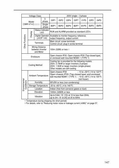
147
200V single- / 3-phase
RUN and ALARM provided as standard LED's
Available to monitor frequency reference, output frequency, output current
Main circuit: screw terminalsControl circuit: plug-in screw terminal
100m (328ft) or less †
Open chassis IP20, Open chassis IP20 (Top-closed type),or enclosed wall-mounted NEMA 1 (TYPE 1)
Open chassis IP20 : -10 to +50°C (14 to 122°F )Open chassis IP20 (Top-closed type) and enclosed wall-mounted NEMA 1 (TYPE 1) : -10 to +40°C (14 to 105°F)
(not frozen)
95%RH or less (non-condensing)
-20 to +60°C (-4 to 140°F)Indoor (free from corrosive gases or dust)
1000m (3280ft) or lessUp to 9.8m / S2 (1G) at 10 to less than 20Hz, up to 2m / S2 (0.2G) at 20 to 50Hz
Env
ironm
enta
lC
ondi
tions
Cooling fan is provided for the following models:200V, 0.75kW or larger inverters (3-phase)200V, 1.5kW or larger inverters (single-phase)Other models are self-cooling
Voltage Class
Oth
er F
unct
ions Dis
play
ModelCIMR-V7*C????
3-phase
Status IndicatorLED
Digital Operator(JVOP-140)
Terminals
Wiring Distance between Inverter
and Motor
Enclosure
Cooling Method
Ambient Temperature
Humidity
Storage Temperature Location
Elevation
Vibration
20P1
B0P1
20P2
B0P2
20P4
B0P4
20P7
B0P7
21P5
B1P5
22P2 24P0
B2P2 B4P0Single-phase
∗ Temperature during shipping (for short period)† For details, refer to “Reducing motor noise or leakage current (n080)” on page 57.

Standard Specifications (400V Class)
148
400V 3-phaseVoltage Class
Inverter Capacity(kVA)
Control Method
Overload Capacity
Accel/Decel Time
Braking Torque
V/f Characteristics
Rated OutputCurrent(A)
Max. OutputFrequency(Hz)
Rated input Voltageand Frequency
Allowable VoltageFluctuation
Allowable FrequencyFluctuation
Frequency ControlRange
Frequency SettingResolution
Frequency ReferenceSignal
Output Frequency Resolution
Frequency Accuracy (Temperature Change)
Max. Output Voltage(V) 3-phase, 380 to 460V (proportional to input voltage)
3-phase, 380 to 460V, 50/60Hz
Digital reference: ± 0.01%, -10 to + 50°C (14 to 122°F)Analog reference: ± 0.5%, 25± 10°C (59 to 95°F)
0 to 10VDC (20kΩ), 4 to 20mA (250Ω), 0 to 20mA (250Ω)pulse train input, frequency setting potentiometer (Selectable)
400Hz(Programmable)
-15 to + 10%
Sine wave PWM (V/f control/vector control selectable)
0.1 to 400Hz
0.01Hz
150% rated output current for one minute
Possible to program any V / f patterm
Short-term average deceleration torque†0.2kW: 150%0.75kW: 100%1.5kW (2HP) : 50%2.2kW(3HP) or more: 20%Continuous regenerative torgue: Approx. 20% (150% with optional braking resistor, braking transistor built-in)
0.00 to 6000 sec. (accel / decel time are independently programmed)
Out
put
Cha
ract
eris
tics
Pow
erS
uppl
yC
ontro
l Cha
ract
eris
tics
±5%
Max. Applicable Motor OutputkW*
ModelCIMR-V7*C????
3-phase 40P2
—
0.37
0.9
1.2
40P4
—
0.55
1.4
1.8
40P7
—
1.1
2.6
3.4
41P5
—
1.5 2.2 3.0 4.0
3.7
4.8
42P2
— — —
4.2
5.5
43P0
5.5
7.2
44P0
7.0
9.2
Single-phase
∗ Based on a standard 4-pole motor for max. applicable motor output.† Shows deceleration torque for uncoupled motor decelerating from 60Hz with the shortest possible deceleration time.
Digital reference: 0.01Hz (less than 100Hz) / 0.1Hz (100Hz or more)Analog reference: 1 / 1000 of max. output frequency

149
Electronic thermal overload relay
Motor coasts to a stop at approx. 250% of inverter rated current
Motor coasts to a stop after 1 minute at 150% of inverter rated output current
Motor coasts to a stop if DC bus voltage exceed 820V
Protected by electronic circuit
Can be set to individual levels during accel / decel, provided / not provided available during coast to a stop
Protected by electronic circuit (overcurrent level)
ON until the DC bus voltage becomes 50V or less.
Seven of the following input signals are selectable:Forward / reverse run (3-wire sequence), fault reset, external fault (NO / NC contact input), multi-step speed operation, Jog command, accel / decel time select,external baseblock (NO / NC contact input), speed searchcommand, accel / decel hold command, LOCAL / REMOTEselection, communication / control circuit terminal selection, emergency stop fault emergency stop alarm, UP/DOWN command, self-test,PID control cancel, PID integral reset / hold,Inverter overheat alarm
Following output signals are selectable (1 NO / NC contact output, 2 photo-coupler outputs) : *Fault, running, zero speed, at frequency, frequency detection (output frequency or set value), duringovertorque detection, during undertorque detection,minorerror, during baseblock, operation mode, inverter run ready, during fault retry, during UV, during speed search, data output through communication, PID feedback loss detection,frequency reference loss, Inverter overheat alarm
Voltage vector control full-range automatic torque boost, slip compensation, DC injection braking current / time at start/stop frequency reference bias /gain, MEMOBUS communications (RS-485 / 422, max. 19.2K bps),PID control, energy-saving control, constant copy,frequency reference with built-in potentiometer, Unit selection for frequency reference setting/desplay
Stops when DC bus voltage is approx. 400V or less
Following items are selectable : Not provided (stops if power loss is 15ms or longer), continuous operation if power loss is approx. 0.5s or shorter, continuous operation
Voltage Class
Motor OverloadProtection
InstantaneousOvercurrent
Overload
OvervoltageUndervoltage
Cooling Fin Overheat
Stall Prevention Level
Ground Fault
Protected by electronic circuit (fan look detection)Cooling Fan Fault
Power ChargeIndication
Standard Functions
Pro
tect
ive
Func
tions
Oth
er F
unct
ions
Momentary Power Loss
ModelCIMR-V7*C????
3-phase
Single-phase
400V 3-phase
40P2
—
40P4
—
40P7
—
41P5
—
42P2
— — —
43P0 44P0
* Minimum permissible load: 5VDC, 10mA (as reference value)
Out
put
Sig
nals
Inpu
tS
igna
ls
Multi-functionInput
Multi-functionOutput

150
RUN and ALARM provided as standard LED's
Available to monitor frequency reference, output frequency, output current
Main circuit: screw terminalsControl circuit: plug-in screw terminal
100m (328ft) or less †
Open chassis IP20, Open chassis IP20 (Top-closed type), or enclosed wall-mounted NEMA 1 (TYPE 1)
95%RH or less (non-condensing)
-20 to +60°C (-4 to 140°F)Indoor (free from corrosive gases or dust)
1000m (3280ft) or lessUp to 9.8m / S2 (1G) at 10 to less than 20Hz, up to 2m / S2 (0.2G) at 20 to 50Hz
Env
ironm
enta
lC
ondi
tions
Open chassis IP20 : -10 to +50°C (14 to 122°F)Open chassis IP20 (Top-closed type) and enclosed wall-mounted NEMA 1 (TYPE 1) : -10 to +40°C (-14 to +105°F)
(not frozen)
Voltage ClassO
ther
Fun
ctio
ns Dis
play
ModelCIMR-V7∗C????
3-phase
Status IndicatorLED
Digital Operator(JVOP-140)
Terminals
Wiring Distance between Inverter
and Motor
Enclosure
Cooling Method
Ambient Temperature
Humidity
Storage Temperature *Location
Elevation
Vibration
Single-phase
* Temperature during shipping (for short period)† For details, refer to “Reducing motor noise or leakage current (n080) on page 57.
400V 3-phase
40P2
–
40P4
–
40P7
–
41P5
–
42P2
– – –
43P0 44P0
Cooling fan is provided for the following models:400V, 1.5kW or larger inverters (3-phase)Other models are self-cooling

Standard Wiring
151
Shielded Twisted-pair shielded wiresP
: Only basic insulation (Protective class 1, overvoltage category2) is provided for thecontrol circuit terminals. Additional insulation may be necessary in the end product toconform to CE requirements
@@@@@@@@e?@@@@@@@@e?@@h?@@h?@@h?@@h?@@h?@@h?
@@@@@@@@e?@@@@@@@@?e@@@@@@@@e?@@@@@@@@?e@@@@@@@@e?@@@@@@@@?e@@@@@@@@e?@@@@@@@@?e
@@@@@@@@@@@@@@@@@@@@@@@@@@@@
@@@@@@@@@@@@@@@@
?@@?@@?@@?@@?@@?@@
?@@@@@@@@?@@@@@@@@
?@@@@@@@@?e@@@@@@@@e?@@@@@@@@?e@@@@@@@@?@@@@@@@@?e@@@@@@@@e?@@@@@@@@?e@@@@@@@@
@@g@@g@@g@@g@@g@@g@@@@@@@@@@@@@@@@
@@@@@@@@@@@@@@@@
* Short-circuit bar should be removed when connecting a DC reactor.† Minimum permissible load: 5VDC, 10mA (as reference value)
U X
DC REACTOR (OPTIONAL)
SHORT-CIRCUIT BAR*
THERMALOVERLOADRELAY
BRAKING RESISTOR(OPTIONAL)
MCCB
R
S
T
FORWARD RUN/STOPREVERSE RUN/STOPEXTERNAL FAULT(NO CONTACT)
FAULT RESET
JOG REFERENCE
MULTI-STEP SPEED REF. 1MULTI-STEP SPEED REF. 2
MULTI-FUNCTIONINPUT
FREQUENCYREF.
PULSE TRAIN INPUT
2kΩ
P P
MEMOBUSCOMMUNICATIONSRS-485/422MAX. 19.2kBPS
R
R
S
S
AM
AC
ANALOG MONITOR / PULSEMONITOR SELECTABLE
ANALOG MONITOR OUTPUT0 TO 10VDC (2mA)
OUTPUT FREQUENCY
P FM
DIGITAL OPERATORFREQUENCY SETTINGPOTENTIOMETER MIN MAX
2 1 B1 B2
U/T1
V/T2
W/T3
R/L1
S/L2
T/L3
S1
S2
S3
S4
S5
S6
S7
RP
FS
FR
FC
SC
SHIELDED CONNECTIONTERMINALREFERENCE PULSE TRAIN(MAX. 33kHz)FREQUENCY SETTINGPOWER SUPPLY(12V 20mA)FREQUENCY REFERENCE0 to 10V (20kΩ)4 to 20mA / 0 to 20mA (250Ω)0V
P2
P1
MA
MB
MC
PC
MULTI-FUNCTIONPHOTOCOUPLER OUTPUT48VDC 50mA OR LESS
RUNN
ING
FREQ
UENC
Y AG
REED
FAULT
MULTI-FUNCTIONCONTACT OUTPUT250VAC 1A OR LESS30VDC 1A OR LESS
IM
FOR SINGLE-PHASE.USE R/L1 AND S/L2.
P
P
TERMINAL RESISTANCE(1/2W. 120Ω)
†

Connection Example of Braking Resistor
152
(R)
(S)
(T)
L1(R)B1 B2
N/L2(S)
L3(T)U/T1
MOTOR
V/T2
W/T3
3-PHASEPOWERSUPPLY
ONMC
THRX
MCTHRX OFF
TRX
FAULT CONTACT
TRX
BRAKING RESISTOR UNITOVERLOAD RELAY TRIP CONTACT
MC
MCCBMC
MA MC SA
SA
SA
Use sequencer to break power supply side on overload relay trip contact
OVERLOAD RELAYTRIP CONTACT
BRAKINGRESISTOR
IM
* Disable stall prevention during deceleration by setting n092 to 1 whenusing a Braking Resistor Unit. The motor may not stop within thedeceleration time if this setting is not changed.

Terminal Description
153
Type Terminal Name Function (Signal Level)
Mai
n C
ircui
tC
ontr
ol C
ircui
tIn
put
Out
put
Seq
uenc
eF
requ
ency
refe
renc
eM
ulti-
func
tion
cont
act o
utpu
t
Com
mun
icat
ion
Circ
uit T
erm
inal
ME
MO
BU
S
com
mun
icat
ions
R/L1, S/L2,T/L3U/T1,V/T2,W/T3
B1, B2
+2, +1
+1, –
S1
AM
AC
R+
S-
S+
R-
AC power supplyinput
Inverter output
Braking resistor connectionDC reactorconnection
DC power supply input
Grounding
NO contact outputNC contact outputContact output commonPhoto-coupler output 1Photo-coupler output 2Photo-coupler output common
Analog monitor common
Analog monitor output †
Communications input (+)
Communications output (–)
Communications output (+)
Communications input (–)
Inverter output
Use main circuit power input.(Use terminals R/L1 and S/L2 for single-phase inverters. Never use terminal T/L3.)
Braking resistor connection
When connecting optional DC reactor, remove themain circuit short-circuit bar between +2 and +1.
For grounding (according to the local groundingcode)
DC power supply input (+1: positive -: negative) *
Factory setting: Fault reset
Factory setting: External fault (NO contact)
Factory setting closed: REV run open: FWD run
Factory setting closed: FWD run open: REV run
Factory setting: fault
Factory setting: Output frequency 0 to +10V
MEMOBUS communicationRun through RS-485 orRS-422.
Factory setting: RunFactory setting: Frequency agreed
0V
0V
Photo-couplerinsulation,24VDC,8mA
Contact capacity250VAC 1A or less,30VDC 1A or less
Photo-coupler output+48VDC, 50mA orless
0 to +10VDC, 2mA orless, 8-bitresolution
RS-485/422MEMOBUS protocol,19.2 kps max.
0V
Factory setting: Jog reference
Factory setting: Multi-step speed reference 2
Factory setting: Multi-step speed reference 1
For control signal
33kHz max.
+12V (permissible current 20mA max.)
MAMBMCP1P2PC
SC
S7
S6
S5
S4
S3
S2
RP
FS
Frequency reference common
FR
FC
Multi-function input selection common
Multi-function input selection 7
Multi-function input selection 6
Multi-function input selection 5
Multi-function input selection 4
Multi-function input selection 3
Multi-function input selection 2
Multi-function input selection 1
Master speed reference pulse train input
Master speed frequency reference
Power for frequency setting
0 to +10VDC (20kΩ) or 4 to 20mA (250kΩ) or 0 to 20mA (250Ω) (1/1000 resolution)
‡
* DC power supply input terminal is not applied to CE/UL standards.† Can be swiched to pulse monitor output.‡ Minimum permissible load: 5VDC, 10mA (as reference value)

154
Sequence input connection with NPN/PNP transistor
Sequence connection with NPN transistor (0V common)
When connecting sequence inputs(S1 to S7) with transistor, turn the rotary switch SW1 depending on the polarity(0V common: NPN side, +24V common: PNP side).Factory setting: NPN side
Multi-fuctioninput
Forward run / stop
Reverse run/ stop
External fault (NO)
Fault reset
JOG command
Multi-step speed reference 1
Multi-step speed reference 2
S1
S2
S3
S4
S5
S6
S7
SC PNP
SW1
VS-606V7
NPN+24V
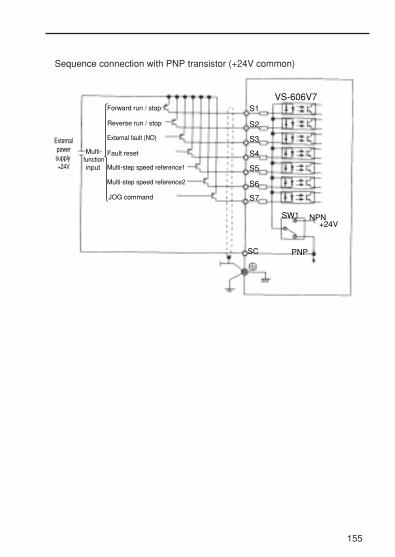
Sequence connection with PNP transistor (+24V common)
155
Externalpowersupply +24V
Multi-functioninput
Forward run / stop
Reverse run / stop
Fault reset
JOG command
Multi-step speed reference 1
Multi-step speed reference2
External fault (NO)
S1
S2
S3
S4
S5
S6
S7
SC PNP
SW1
VS-606V7
NPN+24V

Dimensions / Heat Loss
Fig. 1
156Fig. 2
1.5
(0.0
6)
8.5(0.33)
1.5
(0.0
6)
8.5(0.33)
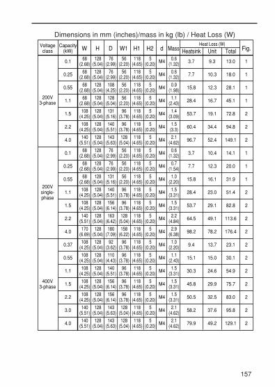
Dimensions in mm (inches)/mass in kg (lb) / Heat Loss (W)
157
Voltageclass
Capacity(kW) W Fig.
200V3-phase
0.1 M4 3.7 9.3 13.0
7.7 10.3 18.0
15.8 12.3 28.1
28.4 16.7 45.1
53.7 19.1 72.8
60.4 34.4 94.8
96.7 52.4 149.1
3.7 10.4 14.1
7.7 12.3 20.0
15.8 16.1 31.9
28.4 23.0 51.4
53.7 29.1 82.8
64.5 49.1 113.6
98.2 78.2 176.4
9.4 13.7 23.1
15.1 15.0 30.1
30.3 24.6 54.9
45.8 29.9 75.7
50.5 32.5 83.0
58.2 37.6 95.8
79.9 49.2 129.1
M4
M4
M4
M4
M4
M4
M4
M4
M4
M4
M4
M4
M4
M4
M4
M4
M4
M4
M4
M4
0.25
0.55
1.1
1.5
2.2
4.0
0.1
0.25
0.55
1.1
1.5
2.2
4.0
0.37
0.55
1.1
1.5
2.2
3.0
4.0
68(2.68)
68(2.68)
68(2.68)
68(2.68)
108(4.25)
108(4.25)
140(5.51)
68(2.68)
68(2.68)
68(2.68)
108(4.25)
108(4.25)
140(5.51)
170(6.69)
108(4.25)
108(4.25)
108(4.25)
108(4.25)
108(4.25)
140(5.51)
140(5.51)
1
1
1
1
2
2
2
1
1
1
2
2
2
2
2
2
2
2
2
2
2
200Vsingle-phase
400V3-phase
H
128(5.04)
128(5.04)
128(5.04)
128(5.04)
128(5.04)
128(5.04)
128(5.04)
128(5.04)
128(5.04)
128(5.04)
128(5.04)
128(5.04)
128(5.04)
128(5.04)
128(5.04)
128(5.04)
128(5.04)
128(5.04)
128(5.04)
128(5.04)
128(5.04)
D
76(2.99)
76(2.99)
108(4.25)
128(5.04)
131(5.16)
140(5.51)
143(5.63)
76(2.99)
76(2.99)
131(5.16)
140(5.51)
156(6.14)
163(6.42)
180(7.09)
92(3.62)
110(4.43)
140(5.51)
156(6.14)
156(6.14)
143(5.63)
143(5.63)
W1
56(2.20)
56(2.20)
56(2.20)
56(2.20)
96(3.78)
96(3.78)
128(5.04)
56(2.20)
56(2.20)
56(2.20)
96(3.78)
96(3.78)
128(5.04)
158(6.22)
96(3.78)
96(3.78)
96(3.78)
96(3.78)
96(3.78)
128(5.04)
128(5.04)
H1
118(4.65)
118(4.65)
118(4.65)
118(4.65)
118(4.65)
118(4.65)
118(4.65)
118(4.65)
118(4.65)
118(4.65)
118(4.65)
118(4.65)
118(4.65)
118(4.65)
118(4.65)
118(4.65)
118(4.65)
118(4.65)
118(4.65)
118(4.65)
118(4.65)
H2
5(0.20)
5(0.20)
5(0.20)
5(0.20)
5(0.20)
5(0.20)
5(0.20)
5(0.20)
5(0.20)
5(0.20)
5(0.20)
5(0.20)
5(0.20)
5(0.20)
5(0.20)
5(0.20)
5(0.20)
5(0.20)
5(0.20)
5(0.20)
5(0.20)
Mass Heatsink Unit Total0.6
(1.32)
0.6(1.32)
0.9(1.98)
1.1(2.43)
1.4(3.09)
1.5(3.3)
2.1(4.62)
0.6(1.32)
0.7(1.54)
1.0(2.20)
1.5(3.31)
1.5(3.31)
2.2(4.84)
2.9(6.38)
1.0(2.20)
1.1(2.43)
1.5(3.31)
1.5(3.31)
1.5(3.31)
2.1(4.62)
2.1(4.62)
dHeat Loss (W)

Recommended Peripheral Devices
It is recommended that the following peripheral devices should be mountedbetween the AC main circuit power supply and VS-606V7 input terminalsR/L1, S/L2, and T/L3.
• MCCB (Molded-case circuit breaker) / fuse : Be sure to connect it for wiring protection.
• Magnetic contactor: Mount a surge suppressor on the coil (refer to the table shown below.)When using a magnetic contactor to start and stop the inverter, do notexceed one start per hour.
Recommended MCCB magnetic contactor, and fuse
• 200V 3-phase
• 200V single-phase
• 400V 3-phase
VS-606V7 model V7 * *20P1
V7 * *20P2
V7 * *20P4
V7 * *20P7
V7 * *21P5
V7 * *22P2
V7 * *24P0
0.3 0.6 1.1 1.9 3.0 4.2 6.7
0.8 1.6 3 5 8 11 17.5
5A 5A 5A 10A 20A 20A 30A
5A 5A 5A 10A 20A 20A 30A
HI-7E HI-7E HI-7E HI-7E HI-10-2E
HI-10-2E
HI-20E
Capacity (kVA)
Rated Output Current (A)
Fuse ( UL Class RK5 )
MCCB type NF30(MITSUBISHI)Magnetic contactor type HI(YASKAWA CONTROL)
VS-606V7 model V7 * *B0P1
V7 * *B0P2
V7 * *B0P4
V7 * *B0P7
V7 * *B1P5
V7 * *B2P2
V7 * *B4P0
0.3 0.6 1.1 1.9 3.0 4.2 6.7
0.8 1.5 3 5 8 11 17.5
5A 5A 10A 20A 20A 40A 50A
HI-7E HI-7E HI-7E HI-15E HI-20E HI-30EHI-10-2E
Capacity (kVA)
5A 5A 10A 20A 20A 40A 50AFuse ( UK Class RK5 )
Rated Output Current (A)MCCB type NF30, NF50(MITSUBISHI)Magnetic contactor type HI(YASKAWA CONTROL)
VS-606V7 model V7 * *40P2
V7 * *40P4
V7 * *40P7
V7 * *41P5
V7 * *42P2
V7 * *43P0
V7 * *44P0
0.9 1.4 2.6 3.7 4.2 5.5 7.0
5A 5A 5A 10A 10A 20A 20A
1.2 1.8 3.4 4.8 5.5 7.2 9.2
5A 5A 5A 10A 10A 20A 20A
HI-7E HI-7E HI-7E HI-10-2E
HI-10-2E
HI-10-2E
HI-10-2E
Capacity (kVA)
Fuse ( UK Class RK5 )
Rated Output Current (A)MCCB type NF30, NF50(MITSUBISHI)Magnetic contactor type HI(YASKAWA CONTROL)
158

Surge suppressors
• Ground fault interrupter:Select a ground fault interrupter not affected by high frequencies. Toprevent malfunctions, the current should be 200mA or more and theoperating time 0.1 sec. or more.Example : • NV series by Mitsubishi Electric Co., Ltd. (manufactured in
1988 and after)
• EGSG series by Fuji Electric Co., Ltd. (manufactured in 1984and after)
• AC and DC reactor :Install an AC reactor to connect to a power supply transformer of largecapacity (600kVA or more) or to improve power factor on the powersupply side.
• Noise filter: Use a noise filter exclusively for inverter if radio noise generated from theinverter causes other control devices to malfunction.
1. Never connect a general LC/RC noise filter to the inverter outputcircuit. 2. Do not connect a phase advancing capacitor to the I/O sides and/or asurge suppressor to the output side. 3. When a magnetic contactor is installed between the inverter and themotor, do not turn it ON/OFF during operation.
For the details of the peripheral devices, refer to the catalog.
159
200V to230V
ModelDCR2-
Specifications Code No.Surge Suppressors
Coils and relays
Large size magnetic contactors
Control relaysMY-2,-3 (OMRON)HH-22, -23(FUJI)MM-2, -4 (OMRON)
50A22E
10A25C
250VAC0.5µF 200Ω
250VAC0.1µF 100Ω
C002417
C002482
NOTE

Constants List
• Addition of constants accompanied by the upgraded software version
The constants marked with #1, #2, and #3 are applicable for the followingupgraded software version Nos.:
#1: Applicable for software version No. VSP 010015 or later
#2: Applicable for software version No. VSP 010020 or later
#3: Applicable for software version No. VSP 010024
• Constants that can be changed during operationThe constants whose numbers are in bold can be changed duringoperation.
160
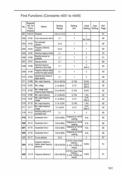
First Functions (Constants n001 to n049)
161
No.
001 0101H
002 0102
003 0103
004 0104
005 0105
Name SettingRange
RegisterNo. forTrans-mission
SettingUnit
InitialSetting
UserSetting
Ref.Page
Password 0 to 4, 6, 12,13 1 1 41
1 450 (Note 1) (Note 6)
1 490
1 1
1 0
0, 1
0 to 3
0 to 9
0, 1
Run command selectionFrequency reference selection
Control mode selection (Note 6)
006 0106 1 00, 1Selecting reverse run prohibited
007 0107 1 00, 1Stop key function
008 0108 1
50
70
51
69
500(Note 5)0, 1Selecting frequency
reference in local mode
009 0109 1 00, 1Frequency reference settingmethod from digital operator
010 010A 1 00, 1Detecting fault contact ofdigital operator
011 010B 0.1Hz 50.0Hz50.0 to 400.0HzMax. output frequency
012 010C 0.1V 200.0V(Note 2)0.1 to 255.0VMax. voltage
013 010D 0.1Hz 50.0Hz0.2 to 400.0HzMax. voltage outputfrequency (base frequency)
014 010E 0.1Hz 1.3Hz0.1 to 399.9HzMid. output frequency
015 010F 0.1V
50
49
42
42
42
42
4212.0V(Note 2)0.1 to 255.0VMid. output frequency
voltage016 0110 0.1Hz 1.3Hz0.1 to 10.0HzMin. output frequency
017 0111 0.1V 12.0V(Note 2)0.1 to 50.0VMin. output frequency
voltage
018 0112 1 00, 1Selecting setting unit ofaccel/decel time
019 0113 Depend on n018setting
10.0s0.00 to 6000sAcceleration time 1
020 0114 Depend on n018setting 10.0s0.00 to 6000sDeceleration time 1
021 0115 Depend on n018setting 10.0s0.00 to 6000sAcceleration time 2
022 0116 Depend on n018setting 10.0s0.00 to 6000sDeceleration time 2
023 0117 1 00 to 3
42
42
56
56
56
56
56
57
6.00Hz
0.00Hz
51
51
S-curve selection
Selecting stopping method
024 0118Frequency reference 1(Master speed frequencyreference)
0.00 to 400.0Hz
0.01Hz (less than100Hz) /
0.1Hz (100Hz ormore)
025 0119 Frequency reference 2 0.00 to 400.0Hz
0.01Hz (less than100Hz) /
0.1Hz (100Hz ormore)

162
No. Name SettingRange
RegisterNo. forTrans-mission
SettingUnit
InitialSetting
UserSetting
Ref.Page
026 011A Frequency reference 3 0.00 to 400.0Hz 0.00Hz
0.01Hz (less than100Hz) /
0.1Hz (100Hz ormore)
027 011B Frequency reference 4 0.00 to 400.0Hz 0.00Hz0.01Hz (less than
100Hz) /0.1Hz (100Hz or
more)
028 011C Frequency reference 5 0.00 to 400.0Hz 0.00Hz0.01Hz (less than
100Hz) /0.1Hz (100Hz or
more)
029 011D Frequency reference 6 0.00 to 400.0Hz 0.00Hz0.01Hz (less than
100Hz) /0.1Hz (100Hz or
more)
030 011E Frequency reference 7 0.00 to 400.0Hz 0.00Hz0.01Hz (less than
100Hz) /0.1Hz (100Hz or
more)
031 011F Frequency reference 8 0.00 to 400.0Hz 0.00Hz0.01Hz (less than
100Hz) /0.1Hz (100Hz or
more)
032 0120 Jog frequency 0.00 to 400.0Hz 6.00Hz0.01Hz (less than
100Hz) /0.1Hz (100Hz or
more)
033 0121 Frequency reference upper limit 0 to 110% 100%1%
034 0122 Frequency reference lower limit 0 to 110% 0%1%
036 0124 Motor rated current0 to 150% ofinverter rated
current(Note 3)0.1A 87
037 0125Electronic thermal motorprotection selection 0 to 2 01
038 0126Electronic thermal motorprotection time constantsetting
1 to 60 min 8min1min
039 0127 Selecting cooling fanoperation 0, 1 0
51
51
51
51
51
51
52
54
54
035 0123Selecting setting/displaying unit of frequency reference
0 to 3999 01 121
87
87
891
040#3 0128 Motor rotation direction 0, 1 0 321
041#3 0129 Acceleration time 3 0.00 to 6000s 10.0s 55
Depend on n018 setting
042#3 012A Deceleration time 3 0.00 to 6000s 10.0s 55
Depend on n018 setting
043#3 012B Acceleration time 4 0.00 to 6000s 10.0s 55
Depend on n018 setting
044#3 012C Acceleration time 4 0.00 to 6000s 10.0s 55
Depend on n018 setting

163
Second Functions (Constants n050 to n079)
No. Name SettingRange
RegisterNo. forTrans-mission
SettingUnit
InitialSetting
UserSetting
Ref.Page
050 0132Multi-function input selection 1 (Terminal S1) 1 1
051 0133 Multi-function input selection 2 (Terminal S2) 1 2
052 0134 Multi-function input selection 3 (Terminal S3) 1 3
053 0135 Multi-function input selection 4 (Terminal S4) 1 5
054 0136 Multi-function input selection 5 (Terminal S5) 1 6
055 0137 Multi-function input selection 6 (Terminal S6) 1 7
056 0138 Multi-function input selection 7 (Terminal S7) 1 10
057 0139 Multi-function output selection 1 1 0
058 013A Multi-function output selection 2 1 1
059 013B Multi-function output selection 3 1 2
060 013C Analog frequency reference gain 0 to 255% 1% 100%
061 013D Analog frequency reference bias -100 to 100% 1% 0%
062
065
013E
0141 Monitor output type
Filter time constant for analog frequency reference constant
0.00 to 2.00s 0.01s 0.10s
066 0142 Multi-function analog output (terminal AM-AC) 0 to 5, 6#3
0,1
1
1
0
0
067
068
069
070
071
072
0143
0144
0145
0146
0147
0148
Analog monitor gainAnalog frequency reference gain Analog frequency reference biasAnalog frequency reference filter timeconstantAnalog frequency reference gain
-255 to 255%1%
-100 to 100%
0.00 to 2.00s
-255 to 255
1%
1%
0.01s
1%
100%
0%
0.10s
100%
-100 to 100% 1% 0%Analog frequency reference bias
0.00 to 2.00 0.01 1.00
73
73
73
73
73
73
73
78
78
78
53
53
–
64
65
64
–
–
–
–
–
0 to 7, 8#3, 9#3,10 to 19, 20#3, 21#3
0 to 7, 8#3, 9#3,10 to 19, 20#3, 21#3
0 to 7, 8#3, 9#3,10 to 19, 20#3, 21#3
064#3 0140 Frequency reference loss
detection selection 0,1 1 0 123
1 to 25, 26#3,27#3
1 to 25, 26#3,27#3
1 to 25, 26#3,27#3
1 to 25, 26#3,27#3
1 to 25, 26#3,27#3
1 to 25, 26#3,27#3
1 to 25, 26#3,27#3, 34, 35
073 0149Analog frequency reference filter time constant
0.00 to 2.00s 0.01s 0.01s
074 014A Pulse train frequencyreference gain 0 to 255% 1% 100%
075 014B Pulse train frequency reference bias -100 to 100% 1% 0%
076 014C Pulse train frequency filter time constant 0.00 to 2.00s 0.01s 0.10s –
–
–
–

164
077#2 014D Multi-function analog
input function 0 to 4 1 0 76
76
76
078#2 014E Multi-function analog
input signal selection 0,1 1 0
079#2 014F Frequency reference
bias(FBIAS) value 0 to 50% 1% 10%
No. Name SettingRange
RegisterNo. forTrans-mission
SettingUnit
InitialSetting
UserSetting
Ref.Page
Third Functions (Constants n080 to n119)
Jump frequency range 0.00 to 25.50Hz 0.00Hz0.01Hz
089 0159DC injection brakingcurrent 0 to 100% 50%1%
61
62
No. Name SettingRange
RegisterNo. forTrans-mission
SettingUnit
InitialSetting
UserSetting
Ref.Page
080 0150 Carrier frequency selection 1 to 4, 7 to 9 1 4 (Note 4)
081 0151 Momentary power loss ridethrough method 0 to 2 1 0
082 0152 Automatic retry attempts 0 to 10 times 1 0
083 0153 Jump frequency 1 0.00 to 400.0Hz 0.00Hz
67
56
61
61
0.01Hz (less than100Hz) /
0.1Hz (100Hz ormore)
084 0154 Jump frequency 2 0.00 to 400.0Hz 0.00Hz
0.01Hz (less than100Hz) /
0.1Hz (100Hz ormore)
085 0155 Jump frequency 3 0.00 to 400.0Hz 0.00Hz
0.01Hz (less than100Hz) /
0.1Hz (100Hz ormore)
086 0156
090 015A DC injection braking timeat stop 0.0 to 25.5% 0.5s
(Note 2)0.1s
61
61
71
095 015FFrequency detection (multi-function contact output)
0.00 to 400.0Hz 0.00Hz
0.01Hz (less than100Hz) /
0.1Hz (100Hz ormore)
091 015B DC injection braking timeat start 0.0 to 25.5% 0.0s0.1s
092 015C Stall prevention during deceleration 0,1 01
093 015D Stall prevention during acceleration 30 to 200% 170%1%
094 015EStall prevention during running 30 to 200% 160%1%
096 0160 Overtorque detection function selection 1 0 to 4 01
097 0161 Overtorque/Undertorque detection function selection 2 0,1 01
098 0162 Overtorque detection level 30 to 200% 160%1%
099 0163 Overtorque detection time 0.1 to 10.0s 0.1s0.1s
60
85
83
84
59
59
59
59
62
100 0164 Hold output frequencysaving selection 0,1 01 75

165
109 016DTorque compensation voltage limitter 0 to 250% 150%1%
111 016F Slip compensation gain 0.0 to 2.5 0.00.1
112 0170Slip compensation timeconstant
Stall prevention automaticdecrease selection
Accel / decel time duringstall prevention
0.0 to 25.5s 2.0s0.1s
113 0171
0173
0174
Slip correction during regenerative operation 0, 1 01
110 016E Motor no-load current 0 to 99% (Note 3)1%
–
86
86
–
84
85
0, 1 01
0, 1 01
45
115#2
116#2
103 0167 Torque compensation gain 0.0 to 2.5 1.00.1
104 0168 Torque compensationtime constant 0.0 to 25.5s 0.3s
44
440.1s
105 0169 Torque compensation ironloss
0.0 to 6550(note 3)
0.01W (less than1000W) /
1W (1000W ormore)
107 016B Line to neutral (per phase) 0.000 to 65.50Ω (note 3)
0.001Ω (less than10Ω) /
0.01Ω (10Ω ormore)
108 016C Motor leakage inductance 0.00 to 655.0mH (note 3)
0.01mH (less than 100mH) /
0.1mH (100mH or more)
106 016A
44
46
46
46Motor rated slip 0.0 to 20.0Hz (note 3)0.1Hz
No. Name SettingRange
RegisterNo. forTrans-mission
SettingUnit
InitialSetting
UserSetting
Ref.Page
101#3
0165 Speed search decelerationtime
0.1 to 10.0s 2.0s0.1s 62
117#3
0175 Undertorque detectionfunction selection 1
0 to 4 01 126
118#3
0176 Undertorque detection level 0 to 200% 10%1% 126
119#3
0177 Undertorque detection time 0.1 to 10.0s 0.1s0.1s 126
102#3
0166 Speed search operation level
0 to 200% 150%1% 62

Fourth Functions (Constants n120 to n179)
166
No. Name SettingRange
RegisterNo. forTrans-mission
SettingUnit
InitialSetting
UserSetting
Ref.Page
120 0178 Frequency reference 9 0.00 to 400.0Hz 0.00Hz
0.01Hz (less than100Hz) /
0.1Hz (100Hz ormore)
121 0179 Frequency reference 10 0.00 to 400.0Hz 0.00Hz
0.01Hz (less than100Hz) /
0.1Hz (100Hz ormore)
122 017A Frequency reference 11 0.00 to 400.0Hz 0.00Hz
0.01Hz (less than100Hz) /
0.1Hz (100Hz ormore)
123 017B Frequency reference 12 0.00 to 400.0Hz 0.00Hz0.01Hz (less than
100Hz) /0.1Hz (100Hz or
more)
124 017C Frequency reference 13 0.00 to 400.0Hz 0.00Hz
0.01Hz (less than100Hz) /
0.1Hz (100Hz ormore)
125 017D Frequency reference 14 0.00 to 400.0Hz 0.00Hz
0.01Hz (less than100Hz) /
0.1Hz (100Hz ormore)
126 017E Frequency reference 15 0.00 to 400.0Hz 0.00Hz
0.01Hz (less than100Hz) /
0.1Hz (100Hz ormore)
127 017F Frequency reference 16 0.00 to 400.0Hz 0.00Hz
51
51
51
51
51
51
51
51
106
109
107
107
107
108
108
108
0.01Hz (less than100Hz) /
0.1Hz (100Hz ormore)
129 0181 PID feedback gain 0.00 to 10.00Hz 1.00
128 0180 PID control selection 0 to 8 01
0.01
131 0183 Integral time (I) 0.0 to 360.0s 1.0
130 0182 Proportional gain (P) 0.0 to 25.0 1.00.1
0.1s
132 0184 Differential time (D) 0.00 to 2.50s 0.000.01s
133 0185 PID offset adjustment -100 to 100% 0%1%
134 0186 Upper limit of integral values
Primary delay time constant of PID output
0 to 100% 100%1%
135 0187 0.0 to 10.0 0.00.1s

167
150 Pulse train outputscaling
0, 1, 6, 12,24, 36,
40 to 45#30196 – 0
151 0197MEMOBUS timeover detection 0 to 4 01
152 0198MEMOBUS frequency reference and frequency monitor unit
0 to 3 01
153 0199 MEMOBUS slave address 0 to 32 01
154 019A MEMOBUS BPS selection 0 to 3 21
155 019B MEMOBUS parity selection 0 to 2 21
156 019C Transmission waiting timeRTS control
10 to 65ms 10ms1ms
157 019D 0, 1 01
91
91
91
91
91
91
91
136 0188 Selection of PID feedback loss detection 0 to 2 01
137 0189 PID feedback loss detection level
0 to 100% 0%1%
138 018A PID feedback loss detection time 0.0 to 25.5 1.00.1s
139 018BEnergy-saving control selection (V/ f control mode)
0, 1 01
140 018C Energy-saving coefficient K2 0.0 to 6550 (Note 7)0.1
141 018D Energy-saving control voltage lower limit (At 60 Hz) 0 to 120% 50%1%
142 018E Energy-saving control voltage lower limit (At 6 Hz) 0 to 25% 12%1%
143 018F Power average time 1 to 200 1(24ms)
1=24ms
144 0190 Search operation voltage Iimit 0 to 100% 0%1%
145 0191 Search operation voltage step (At 100%)
0.1 to 100% 0.5%0.1%
146 0192 Search operation voltage step (At 5%)
0.1 to 10.0% 0.2%0.1%
149 0195Pulse train input scaling 100 to 3300
2500(25kHz)1=10 Hz
No. Name SettingRange
RegisterNo. forTrans-mission
SettingUnit
InitialSetting
UserSetting
Ref.Page
109
109
109
101
101
102
102
103
103
103
103
82
65

168
178 01B2 Fault historyStores, displaysmost recent 4
alarms–Setting disabled
179 01B3 Software version No.Displays lower-place 4 digits of
software No.–
164 01A4 PID feedback value selection 0 to 5 01
176 01B0 Constant copy function selection
rdy, rEd,Cpy, vFy, vA, Sno
rdy
177 01B1 Constant read selection prohibit 0, 1 01
39
113
112
106
–Setting disabled
No. Name SettingRange
RegisterNo. forTrans-mission
SettingUnit
InitialSetting
UserSetting
Ref.Page
175#1 01AF
Reducing carrier frequency selection at low speed
0, 1 01 68
163 01A3 PID output gain 0.0 to 25.0 1.00.1 109
162 01A2 Time constant of power detection filter 0 to 255
5(20ms)1=4ms 104
166#3 01A6 Input Open-phase
Detection Level 0 to 100% 0%1% 124
167#3 01A7 Input Open-phase
Detection Time 0 to 255s 0s1s 124
168#3 01A8 Output Open-phase
Detection Level 0 to 100% 0%1% 124
169#3 01A9 Output Open-phase
Detection Time 0.0 to 2.0s 0.0s0.1s 124
173#3 01AD DC injection braking
proportional gain 1 to 999 83(0.083)1=0.001 –
174#3 01AE DC injection braking
integral time constant 1 to 250 25(100ms)1=4ms –
160 01A0 Upper voltage limit for energy-saving control (At 6Hz) 0 to 25% 16%1% 102
159 019FUpper voltage limit for energy-saving control (At 60Hz) 0 to 120% 120%1% 102
Motor code(Energy-saving control)158 019E 0 to 70 (Note 7)1 101
161 01A1 0 to 100%Search operation power detection hold width
10%1% 104
164 01A4 0 to 5 01 106

169
Notes:
4. Changes depending on inverter capacity. Refer to page 67.5. Initial setting of the model with digital operator JVOP-140 (with potentiometer) is 0. Setting can be set to 1 by constant initialization.
2. Upper limit of setting range and initial setting are doubled at 400V class.1. Not initialized by constant initialization.
3. Changes depending on inverter capacity. Refer to the next page.
No.
6. When control mode selection (n002) is changed, initial setting corresponds to the control mode.
* Values are doubled with 400V class.
NameV / f control mode
(n002 = 0)Vector control mode
(n002 = 1)
n014 Mid. output frequency 1.3Hzn015 Mid. output frequency voltage 12.0V*n016 Min. output frequency 1.3Hzn017 Min. output frequency voltage 12.0V*n104 Torque compensation time constant 0.3sn111 Slip compensation gain 0.0n112 Slip compensation gain time constant 2.0s
3.0Hz11.0V*1.0Hz4.3V*0.2s1.00.2s
7. Changes depending on inverter capacity. Refer to page 101.
No.
< 200V class 3-phaseName Unit
– Inverter capacity kW 0.1kW 0.25kW 0.55kW 1.1kW 1.5kW 2.2kW – 4.0kWn036 Motor rated current A 0.6 1.1 1.9 3.3 6.2 8.5 – 14.1
n105Torque compensationiron loss W 1.7 3.4 4.2 6.5 11.1 11.8 – 19
n106 Motor rated slip Hz 2.5 2.6 2.9 2.5 2.6 2.9 – 3.3
n107Line to neutral (per phase)* Ω 17.99 10.28 4.573 2.575 1.233 0.8 – 0.385
n108 Motor leakage inductance MH 110.4 56.08 42.21 19.07 13.4 9.81 – 6.34n110 Motor no-load current % 72 73 62 55 45 35 – 32
No.
< 200V class single-phaseName Unit
Initial Setting
Initial Setting– Inverter capacity kW 0.1kW 0.25kW 0.55kW 1.1kW 1.5kW 2.2kW – 4.0kW
n036 Motor rated current A 0.6 1.1 1.9 3.3 6.2 8.5 – 14.1
n105Torque compensationiron loss W 1.7 3.4 4.2 6.5 11.1 11.8 – 19
n106 Motor rated slip Hz 2.5 2.6 2.9 2.5 2.6 2.9 – 3.3
n107Line to neutral (per phase)*
Ω 17.99 10.28 4.573 2.575 1.233 0.8 – 0.385
n108 Motor leakage inductance MH 110.4 56.08 42.21 19.07 13.4 9.81 – 6.34n110 Motor no-load current % 72 73 62 55 45 35 – 32
Initial settings that change with the inverter capacity
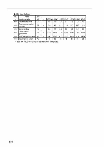
170
No.
< 400V class 3-phaseName Unit
– Inverter capacity kW – 0.37kW 0.55kW 1.1kW 1.5kW 2.2kW 4.0kWn036 Motor rated current A – 0.6 1.0 1.6 3.1 4.2 7.0
n105Torque compensationiron loss W – 3.4 4.0 6.1 11.0 11.7 19.3
n106 Motor rated slip Hz – 2.5 2.7 2.6 2.5 3.0 3.2
n107Line to neutral (per phase)*
Ω – 41.97 19.08 11.22 5.044 3.244 1.514
n108 Motor leakage inductance MH – 224.3 168.8 80.76 53.25 40.03 24.84n110 Motor no-load current % – 73 63 52 45 35
3.0kW7.0
19.3
3.2
1.514
24.8433 33
* Sets the value of the motor resistance for one phase.

171
NOTES

172
NOTES

Revision History
The revision dates and numbers of the revised manuals are given on thebottom of the back cover.
MANUAL NO. TOE-S606-11E© Printed in Japan August 2003 98-06 11
1
Date ofprinting
Date of printing
June 1998 First edition
September 1998 Partly revised
2November 1998 Revision: Product name changed from VS miniV7 to VS-606V7
3May 1999 Addition: Constant copy function
Addition: Energy-saving control mode
Addition: PID control mode
Chapter 6
Notes for safeoperation
4Jury 1999 Partly revised
5November 1999 Partly revised
6February 2000 Partly revised
7May 2000 Partly Deleted
10May 2003 Partly revised
11August 2003 Addition: Description of rotation derectionselection
8October 2001 Revision: Warning/Caution mark
Front cover9September 2002 Deletion: CE and UL marks
Notes for safeoperation
Addition: Warnings for CE Markings
Revision: Changed “enclosed wall-mounted typeNEMA 1” to “enclosed wall-mounted typeNEMA 1 (TYPE 1)”
Section Revised Content
Date of originalpublication
Revision number
Rev.No.–
Addition: Troubleshooting
Addition: Minimum permissible load formulti-function contact outputs
Chapter 8
Addition: Description of using Inverters forelevating machines
Chapter 6
Chapter 9
Chapter 5

Date of printing Section Revised ContentRev.No.
Revision: Description of using four acceleration/deceleration time patterns
Addition: Description of orvertorque/undertorque detection function selection 2
Addition: Setting 6 Frequency ReferenceMonitor, for analog output terminals
Addition: Monitor data 0029AH, 002AH, and002EH
Addition: Description of the processing methodfor frequency reference loss
Addition: Description of Input/Output open-phases detection
Addition: Description of undertorque detection
Addition: Alarm UL3, oH3, PF, LF, and UL3
Addition: New constants n40 to n044, n064, n101, n102, n117 to n119, n166 to n169, n173,and n174
Chapter 7
Chapter 6
Chapter 9
Addition: Revision historyEndsheet onback cover

VS-606V7 Series
INSTRUCTION MANUAL
YASKAWA
YASKAWA ELECTRIC CORPORATION
β
In the event that the end user of this product is to be the military and said product is to be employed in any weapons systems or the manufacture thereof, the export will fall under the relevant regulations as stipulated in the Foreign Exchange and Foreign Trade Regulations. Therefore, be sure to follow all procedures and submit all relevant documentation according to any and all rules, regulations and laws that may apply.
Specifications are subject to change without notice for ongoing product modifications and improvements.
© 1998-2003 YASKAWA ELECTRIC CORPORATION. All rights reserved.
MANUAL NO. TOE-S606-11E Printed in Japan August 2003 98-6 WA
03-4③11
IRUMA BUSINESS CENTER480, Kamifujisawa, Iruma, Saitama 358-8555, JapanPhone 81-42-962-5696 Fax 81-42-962-6138
YASKAWA ELECTRIC AMERICA, INC.2121 Norman Drive South, Waukegan, IL 60085, U.S.A.Phone 1-847-887-7000 Fax 1-847-887-7370
MOTOMAN INC. HEADQUARTERS805 Liberty Lane West Carrollton, OH 45449, U.S.A.Phone 1-937-847-6200 Fax 1-937-847-6277
YASKAWA ELETRICO DO BRASIL COMERCIO LTD.A.Avenida Fagundes Filho, 620 Bairro Saude-Sao Paulo-SP, Brazil CEP: 04304-000Phone 55-11-5071-2552 Fax 55-11-5581-8795
YASKAWA ELECTRIC EUROPE GmbHAm Kronberger Hang 2, 65824 Schwalbach, GermanyPhone 49-6196-569-300 Fax 49-6196-569-398
Motoman Robotics Europe ABBox 504 S38525 Torsas, SwedenPhone 46-486-48800 Fax 46-486-41410
Motoman Robotec GmbHKammerfeldstraβe 1, 85391 Allershausen, GermanyPhone 49-8166-90-100 Fax 49-8166-90-103
YASKAWA ELECTRIC UK LTD.1 Hunt Hill Orchardton Woods Cumbernauld, G68 9LF, United KingdomPhone 44-1236-735000 Fax 44-1236-458182
YASKAWA ELECTRIC KOREA CORPORATIONKfpa Bldg #1201, 35-4 Youido-dong, Yeongdungpo-Ku, Seoul 150-010, KoreaPhone 82-2-784-7844 Fax 82-2-784-8495
YASKAWA ELECTRIC (SINGAPORE) PTE. LTD.151 Lorong Chuan, #04-01, New Tech Park Singapore 556741, SingaporePhone 65-6282-3003 Fax 65-6289-3003
YASKAWA ELECTRIC (SHANGHAI) CO., LTD.No.18 Xizang Zhong Road. Room 1805, Harbour Ring Plaza Shanghai 20000, ChinaPhone 86-21-5385-2200 Fax 86-21-5385-3299
YATEC ENGINEERING CORPORATION4F., No.49 Wu Kong 6 Rd, Wu-Ku Industrial Park, Taipei, TaiwanPhone 886-2-2298-3676 Fax 886-2-2298-3677
YASKAWA ELECTRIC (HK) COMPANY LIMITEDRm. 2909-10, Hong Kong Plaza, 186-191 Connaught Road West, Hong KongPhone 852-2803-2385 Fax 852-2547-5773
BEIJING OFFICERoom No. 301 Office Building of Beijing International Club, 21Jianguomenwai Avenue, Beijing 100020, ChinaPhone 86-10-6532-1850 Fax 86-10-6532-1851
TAIPEI OFFICE9F, 16, Nanking E. Rd., Sec. 3, Taipei, TaiwanPhone 886-2-2502-5003 Fax 886-2-2505-1280
SHANGHAI YASKAWA-TONGJI M & E CO., LTD.27 Hui He Road Shanghai China 200437Phone 86-21-6553-6060 Fax 86-21-5588-1190
BEIJING YASKAWA BEIKE AUTOMATION ENGINEERING CO., LTD.30 Xue Yuan Road, Haidian, Beijing P.R. China Post Code: 100083Phone 86-10-6233-2782 Fax 86-10-6232-1536
SHOUGANG MOTOMAN ROBOT CO., LTD.7, Yongchang-North Street, Beijing Economic Technological Investment & Development Area, Beijing 100076, P.R. ChinaPhone 86-10-6788-0551 Fax 86-10-6788-2878