VRF DX COIL INTERFACE Installation manual - toshiba-klima.rs

IOM
VR
F180
713
Rev
. A
VRF® II SeriesInstallation & Operation Manual
IOM
VR
F180
913
Rev
. A


VRF® II SeriesInstallation & Operation Manual
CONTENTS
I. HANDLING & STORAGE .................................................................................................................. 1 Inspection and Handling Disposal and Recycling Storage
II. GENERAL SAFETY ........................................................................................................................... 2 Authorized Personnel Use Misuse
III. PRODUCT DESCRIPTION ............................................................................................................... 3 Function Applications Features TechnicalSpecifications Approvals
IV. MECHANICAL INSTALLATION ......................................................................................................... 5 Guidelines Mounting Considerations Figure 1. Mounting Orientation Figure 2. Mounting in Relation to Flow of Material
V. ELECTRICAL INSTALLATION .......................................................................................................... 6 General Safety Disconnect Requirements for Permanently Installed Equipment Protective Earth Ground Electrical Connections Conduit Cable Connection VRF II Series Integral Model Only VRF II Series Remote Model Only Figure 3. VRF II Series - Integral Enclosure with Cover Removed - STANDARD Figure 4. VRF II Series - Integral Enclosure with Cover Removed - ADVANCED Figure 5. Power and Ground Connections Figure 6. Main Relay Connections Figure 7. Auxiliary Relay Connections - ADVANCED ONLY Figure 8. VRF II Series - Remote Enclosure with Cover Removed - STANDARD Figure 9. VRF II Series - Remote Enclosure with Cover Removed - ADVANCED Figure 10.VRF II Series - Remote Connection Diagram

SAFETY SYMBOLS
WARNING:
IDENTIFIES CONDITIONS OR PROCEDURES, WHICH IF NOT FOLLOWED, COULD RESULT IN SERIOUS INJURY. RISK OF ELECTRICAL SHOCK.
CAUTION:
IDENTIFIES CONDITIONS OR PROCEDURES, WHICH IF NOT FOLLOWED, COULD RESULT IN SERIOUS DAMAGE OR FAILURE OF THE EQUIPMENT.
VI. SET-UP ........................................................................................................................................... 13 Operation Product Overview - STANDARD Figure 11. Switch Functions Product Overview - ADVANCED Figure 12. Switch Functions Pro-Guard®
Fail-Safe Selection Time Delay Settings - STANDARD Time Delay Settings - ADVANCED Sensitivity Settings - STANDARD Sensitivity Settings - ADVANCED Calibration - Automatic Calibration - Manual - ADVANCED ONLY Calibration - Test - ADVANCED ONLY Figure 13. Magnetic Fob
VII. MAINTENANCE .............................................................................................................................. 19
VIII. TROUBLESHOOTING .................................................................................................................... 19
IX. DIMENSIONAL DRAWINGS ........................................................................................................... 20

1
www.bindicator.com
VRF180913 Rev. A1
I. HANDLING AND STORAGE
SAVE THESE INSTRUCTIONS
INSPECTION AND HANDLING
Do not dispose of the carton or packing materials.
Each package should be inspected upon receipt for damage that may have occurred due to mishandling during
shipping. If the unit is received damaged, notify the carrier or the factory for instructions. Failure to do so may
void your warranty. If you have any problems or questions, consult Customer Support at 800-778-9242.
DISPOSAL AND RECYCLING
This product can be recycled by specialized companies and must not be disposed of in a municipal collection
site. If you do not have the means to dispose of properly, please contact for return and disposal instructions or
options.
STORAGE
If the device is not scheduled for immediate installation following delivery, the following steps should be
observed:
1. Following inspection, repackage the unit into its original packaging.
2. Select a clean dry site, free of vibration, shock and impact hazards.
3. If storage will be extended longer than 30 days, the unit must be stored at temperatures between 32º and 158º F (0º to 70° C) in non-condensing atmosphere with humidity less than 85%.
CAUTION: DO NOT STORE A NON-POWERED UNIT OUTDOORS FOR A PROLONGED PERIOD.
VRF® II SeriesInstallation & Operation Manual

2VRF180913 Rev. A
www.bindicator.com
2
II. GENERAL SAFETY
AUTHORIZED PERSONNEL
Allinstructionsdescribedinthedocumentmustbeperformedbyauthorizedandqualifiedservicepersonnel
only. Before installing the unit, please read these instructions and familiarize yourself with the requirements and
functions of the device. The required personal protective equipment must always be worn when servicing this
device.
USE
The device is solely intended for use as described in this manual. Reliable operation is ensured only if the
instrumentisusedaccordingtothespecificationsdescribedinthisdocument.Forsafetyandwarranty
reasons,useofaccessoryequipmentnotrecommendedbythemanufacturerormodificationofthisdeviceis
explicitlyforbidden.Allservicingofthisequipmentmustbeperformedbyqualifiedservicepersonnelonly.This
device should be mounted in locations where it will not be subject to tampering by unauthorized personnel.
MISUSE
Improper use or installation of this device may cause the following:
• Personalinjuryorharm
• Applicationspecifichazardssuchasvesseloverfill
• Damagetothedeviceorsystem
If any questions or problems arise during installation of this equipment, please contact Customer Support at
800-778-9242.

3
www.bindicator.com
VRF180913 Rev. A3
III. PRODUCT DESCRIPTION
FUNCTION
The VRF® II Series is a point level sensor used to detect the presence or absence of material at a point inside
a tank, bin, or other vessel. Material coming in contact with the unit’s probe causes its output relay to change
state, thereby indicating the presence of material.
Operation of the VRF II Series is based upon the Bindicator® Opti-Sense™ technology to measure changes
in the impedance of the unit’s probe with respect to the ground. At the heart of the unit is a network analyzer
with a built in DSP (Digital Signal Processor) that continuously monitors the probe’s impedance (capacitance,
resistance, and inductance) with respect to ground. When there is a large enough change in the impedance, the
status of the output relay changes to indicate the presence or absence of the material.
APPLICATIONS
This model is ideal for the point level detection of dry bulk materials, liquids, and slurries. It is not appropriate for
conductive materials that will coat, or build up on the probe. It is ideal in the measurement of materials with a
dielectric constant as low as 1.2. Moisture content and bulk density also factor into the unit’s ability to sense low
dielectric materials. Call the manufacturer Applications Department with questions.
FEATURES
Multiplemountingconfigurationsandprobesareavailabletosuitalmostanyapplication
Universalinputpower;ACorDC(seespecificationsforinputranges)
Pro-Guard® probe design
Automatic calibration EZ-CAL™ II
Adjustable time delay
Selectable fail-safe operation (high or low level)
Adjustable Sensitivity

4VRF180913 Rev. A
www.bindicator.com
4
TECHNICAL SPECIFICATIONS
FUNCTIONAL
Power Requirements Universal (± 10%), 120-240 VAC 50/60 Hz or 24-48 VDC
Power Consumption - STANDARD 10 W AC; 3 W DC
Power Consumption - ADVANCED 11 W AC; 4 W DC
Fuse Slow Blow, 1A 300 V (Not User Serviceable)
Operating Temperature
Electronics -40° to 158° F (-40° to 70° C)
Probe -40° to 993° F (-40° to 534° C) depending on probe
Outputs
Main Relay 8 A DPDT @ 240 VAC or 30 VDC (resistive)
Auxiliary Relay - ADVANCED ONLY 0.46 A SPDT @ 150 VAC or 1 A @ 30 VDC
PERFORMANCE
Pressure Rating 150 psi (10.5 kg/cm2) with 3/4” NPT; 50 psi (3.5 kg/cm2) with 11/4” NPT
Time Delay - STANDARD Field Adjustable; 0.2-6 seconds
Time Delay - ADVANCED Field Adjustable; 0-150 seconds
Fail Safe Field Selectable; high/low level
Sensitivity - STANDARD Field Adjustable; minimum 1.5 pf
Sensitivity - ADVANCED Field Adjustable; minimum 0.5 pf
Maximum Particle Size 9/16” (14.3 mm)
PHYSICAL
Enclosure Material Polyester or Epoxy Coated Aluminum or 304 SS
Dual Conduit Entry 3/4” NPT or M20 x 1.5
Extended Pipe Material Galvanized or 316 SS
Shipping Weight Integral, non-extended 10 lb (4.5 kg)
Pollution Degree 2
Installation Category II
Altitude 6,562 ft (2,000 m)
APPROVALS & RATINGS
UL (US and Canada):Ordinary Location Type 4X; IP66Hazardous Location, Type 4X; IP66 (Pending) Explosion Proof Dust Ignition Proof
ATEX/IECex (Pending):Dust and Gas Categories
CEElectromagnetic Compatibility DirectiveLow Voltage Directive

5
www.bindicator.com
VRF180913 Rev. A5
IV. MECHANICAL INSTALLATION
WARNING: REMOVE POWER FROM THE UNIT BEFORE INSTALLING, REMOVING, OR MAKING
ADJUSTMENTS.
GUIDELINES
The following precautions should be observed when installing and operating the VRF II Series units:
• Theinstallationandwiringofthisproductmustcomplywithallnational,federal,state,municipalandlocal codes that apply.
• TheVRFIISeriesisaprecisiondevice-handleitcarefullytopreventdamagetotheprobe.
• Donotallowmoisturetoentertheelectronicsenclosure.ConduitshouldslopedownwardfromtheVRFIISerieshousing.Installdriploops(ordrainfitting)andsealconduitwithsiliconerubberproduct.
CAUTION: ATTEMPTING TO TIGHTEN VRF II SERIES UNITS BY ROTATING THE HOUSING OR PROBE
MAY DAMAGE THE UNIT AND VOID THE WARRANTY.
CAUTION: WHETHER MOUNTING DIRECTLY THROUGH A SIDE WALL, OR PIPE EXTENDED AND
MOUNTED VERTICALLY THOUGH THE TOP OF A VESSEL, NEVER ATTEMPT TO MOUNT THROUGH A
FULL COUPLING.
MOUNTING CONSIDERATIONS
The VRF II Series must be located at the position where level indication is desired. The probes may be mounted
through the top or side wall of the vessel. To ensure reliable operation, observe the following guidelines when
choosing the mounting location. Figure 1. Mounting Orientation
• Donotmounttheprobedirectlyintheflowofmaterial.
• Donotmounttheprobeinanareawhereitcancontactthe
vessel.
• MountprobesothatthePro-Guard® section of the probe is
fully in the tank or chute where level of product will come and
go from it.
• Ininstallationswheretherearemultipleprobes,donotmount
the probes within 12 inches (30.5 cm) of each other.
• Ifprobeswillbetipextended,contactfactoryforfurther
instructions.
• Remotecable,betweenprobeandelectronics,cannotexceed100feet(30.5m).
• Ifnecessary,useabaffletoprotecttheprobefromfallingmaterial.Thebaffleshouldbeplaced6to8inches
(15 to 20 cm) above the probe so that material will not become packed.

6VRF180913 Rev. A
www.bindicator.com
6
Figure 2. Mounting In Relation To Flow of Material
YES YES
BAFFLE
YES
V. ELECTRICAL INSTALLATION
WARNING: REMOVE POWER FROM THE UNIT BEFORE INSTALLING, REMOVING, OR MAKING
ADJUSTMENTS
GENERAL SAFETY
When using electrical equipment, you should always follow basic safety precautions, including the following:
• Theinstallationandwiringofthisproductmustcomplywithallnational,federal,state,municipal,andlocal codes that apply.
• Properlygroundtheenclosuretoanadequateearthground.
• Donotmodifyanyfactorywiring.Connectionsshouldonlybemadetotheterminalsdescribedinthissection.
• AllconnectionstotheVRFIISeriesmustuseconductorswithaninsulationratingof300Vminimum,ratedfor212ºF(105ºC),aminimumflammabilityratingofVW-1,andbeofappropriategaugeforthevoltageandcurrentrequired(seespecifications).
• Donotallowmoisturetoentertheelectronicsenclosure.ConduitshouldslopedownwardfromtheVRF II Series housing. Install drip loops and seal conduit with silicone rubber product.
DISCONNECT REQUIREMENTS FOR PERMANENTLY INSTALLED EQUIPMENT
A dedicated disconnecting device (circuit breaker) must be provided for the proper installation of the unit. If
independent circuits are used for power input and main relay outputs, individual disconnects are required.

7
www.bindicator.com
VRF180913 Rev. A7
Disconnects must meet the following requirements:
• Locatedincloseproximitytothedevice
• Easilyaccessibletotheoperator
• Appropriatelymarkedasthedisconnectforthedeviceandassociatedcircuit
• Sizedappropriatelytotherequirementsoftheprotectedcircuit(SeeSpecifications)
PROTECTIVE EARTH GROUND
To eliminate shock hazards in the unlikely event of an internal insulation breakdown, the unit is provided with
an “earth” lead which must be connected to earth ground. In addition, the input power ground lead must be
connected to the “protective earth” ( ) terminal provided. Wire sizes must be selected such that it can safely
carry the sum total of all circuits’ maximum amperage.
CONDUIT-CABLE CONNECTION
Two threaded female conduit openings are provided in the housing for input and output wiring. When only one
conduit opening is used for installation, the unused opening must be sealed with a suitable type 4X/IP66 plug
with pipe sealant in order to maintain approval requirements.
ELECTRICAL CONNECTIONS
Note: The VRF II Series can be operated from 120-240 VAC 50/60 Hz or 24-48 VDC and provides reverse polarity
protection in the event of a wiring error.
VRF II SERIES INTEGRAL MODEL ONLY
Input Power Connections
1. Refer to Figures 3 or 4 and 5 when connecting input power to the unit.
2. Loosen the housing cover screws and remove cover.
CAUTION: IF THE UNIT WAS SUPPLIED WITH A GASKET AVOID FOLDING, CUTTING OR TEARING
GASKET. DAMAGING THE GASKET CAN ALLOW MOISTURE TO ENTER THE ENCLOSURE AND
DAMAGE THE UNIT.
Note: Two threaded female conduit openings are provided in the housing to separate input and output wiring.
3. Pull approximately 4” of cable through conduit closest to the grounding bracket and strip as follows:
a. Ground – 3/8” (9 to 10 mm)
b. Power Leads – 1/4” (6 to 7 mm)
4. Attach incoming ground lead to grounding bracket as shown in Figure 3 or 4.

8VRF180913 Rev. A
www.bindicator.com
8
Note: The VRF II Series incorporates pluggable terminal blocks for ease of connection. If the terminal block is
unplugged while making connections, ensure it is seated properly when reinstalled.
5. Attach power leads to terminal block as shown in Figure 5.
6. Check that all wires are held tightly in place by lightly pulling each conductor.
Main Relay Connections
7. Refer to Figure 3 or 4 and 6 when connecting to the main relay.
8. Pull approximately 4.5” (11.43 cm) of cable through conduit and strip 1/4” (6 to 7 mm).
9. Attach leads to terminal block as shown in Figure 5.
10. Check that all wires are held tightly in place by lightly pulling each conductor.
For STANDARD models skip to Step 15; for ADVANCED models continue to Step 11.
Auxiliary Relay Connections
11. Refer to Figure 3 or 4 and 7 when connecting to the auxiliary relay.
12. Pull approximately 5.5” (13.97 cn) of cable through conduit and strip 1/4” (6 to 7 mm).
13. Attach leads to terminal block as shown in Figure 5.
14. Check that all wires are held tightly in place by lightly pulling each conductor.
15. Reinstall the gasket, if necessary.
16. Replace cover and tighten screws to 60 in-lb (6.8 n-m) of torque.
VRF II SERIES REMOTE MODEL ONLY
Input Power Connections
1. Refer to Figures 3 or 4 and 5 when connecting input power to the unit.
2. Loosen set screw that locks cover in place.
3. Unscrew the housing cover and remove.
Note: Two threaded female conduit openings are provided in the remote housing to separate input and output
wiring from the remote probe wiring.
4. Pull approximately 6” (15 cm) of cable through conduit closest to grounding bracket and strip as follows:
a. Ground – 3/8” (9 to 10 mm)
b. Power Leads – 1/4” (6 to 7 mm)
5. Attach incoming ground lead to grounding bracket as shown in Figure 5.
Note: The VRF II Series incorporates pluggable terminal blocks for ease of connection. If the terminal block is
unplugged while making connections, ensure it is seated properly when reinstalled.
6. Attach power leads to terminal block as shown in Figure 3 or 4.
7. Check that all wires are held tightly in place by lightly pulling each conductor.

9
www.bindicator.com
VRF180913 Rev. A9
Main Relay Connections
8. Refer to Figure 3 or 4 and 6 when connecting to the main relay.
9. Pull approximately 9” (23 cm) of cable through conduit and strip 1/4 ” (6 to 7 mm).
10. Attach leads to terminal block as shown in Figure 3 or 4.
11. Check that all wires are held tightly in place by lightly pulling each conductor.
Auxiliary Relay Connections - ADVANCED ONLY
12. Refer to Figure 3 or 4 and 7 when connecting to the auxiliary relay.
13. Pull approximately 2.5” (6 cm) of cable through conduit and strip 1/4 ” (6 to 7 mm).
14. Attach leads to terminal block as shown in Figure 7.
15. Check that all wires are held tightly in place by lightly pulling each conductor.
Remote Probe Connections
16. Refer to Figure 8 or 9 and 10 when connecting the remote probe.
17. Pull approximately 2.5” (6 cm) of cable through conduit and strip 3/16 ” (4 to 5 mm).
18. Connect factory supplied cable to terminals block as shown in Figure 10.
19. Check that all wires are held tightly in place by lightly pulling each conductor.
20. Replace cover.
21. Tighten set screw to lock cover in place.
22. Loosen the remote probe housing cover screws and remove cover.
CAUTION: IF THE UNIT WAS SUPPLIED WITH A GASKET AVOID FOLDING, CUTTING, OR TEARING
GASKET. DAMAGING THE GASKET CAN ALLOW MOISTURE TO ENTER THE ENCLOSURE AND
DAMAGE THE UNIT.
23. Pull approximately 4” (10 cm) of cable through conduit and strip 3/16 ” (4 to 5 mm).
24. Connect factory supplied cable to terminals block as shown in Figure 3 or 4.
25. Check that all wires are held tightly in place by lightly pulling each conductor.
26. Reinstall the gasket, if necessary.
27. Replace cover and tighten screws to 60 in-lb (6.8 n-m) of torque.

10VRF180913 Rev. A
www.bindicator.com
10
Figure 3. VRF II Series: Integral Enclosure with Cover Removed - STANDARD
Main RelayConnections
Power & GroundConnections
Dip Switch SW1
Alarm LED
Power LED
Notes:1) For Safety and to insure Proper Operation, Attach Ground Wire to an Adequate Earth Ground.
To Earth GroundNote 1
Figure 4. VRF II Series: Integral Enclosure with Cover Removed - ADVANCED
Main RelayConnections
Power & GroundConnections
Auxillary RelayConnections
Dip Switch
Power LED Alarm LED
Cal Button
To Earth GroundNote 1
Notes:1) For Safety and to insure Proper Operation, Attach Ground Wire to an Adequate Earth Ground.

11
www.bindicator.com
VRF180913 Rev. A11
Figure 5. Power and Ground Connections Figure 6. Main Relay Connections Power & Ground Connections
PRIMARYGROUND
Figure 7. Auxiliary Relay Connections - ADVANCED ONLY
Figure 8. VRF II Series Remote Enclosure with Cover Removed - STANDARD
Power & GroundConnections
Dip Switch SW1
Remote ConnectionDiagram
Main RelayConnections
Notes:1) For Safety and to insure Proper Operation, Attach Ground Wire to an Adequate Earth Ground.
To Earth GroundNote 1

12VRF180913 Rev. A
www.bindicator.com
12
Figure 9. VRF II Series Remote Enclosure with Cover Removed - ADVANCED
Auxillary RelayConnections
Power & GroundConnections
Dip Switch
Power LED
Remote ConnectionDiagram
Alarm LED
Main RelayConnections
Cal Button
To Earth GroundNote 1
Notes:1) For Safety and to insure Proper Operation, Attach Ground Wire to an Adequate Earth Ground.
Figure 10. VRF II Series - Remote Connection Diagram
GND.=GUARD =
ACT.=
GRNBLUERED
WIRING COLORS
Remote Connection Diagram
REMOTE ELECTRONICS REMOTE PROBE SENSOR
To Earth GroundNote 2
Notes:1) Maximum cable length is 100ft.2) For Safety and to insure Proper Operation, Attach Ground Wire to an Adequate Earth Ground.

13
www.bindicator.com
VRF180913 Rev. A13
VI. SET-UP
WARNING: REMOVE POWER FROM THE UNIT BEFORE INSTALLING, REMOVING OR MAKING
ADJUSTMENTS.
OPERATION
The VRF II Series will begin operating and the green Power LED will be illuminated when power is applied. Once
properly installed, the VRF II Series should be calibrated (refer to Calibration Section) when material is below
the probe. The status of the red Alarm LED is determined by the selected fail-safe mode and whether or not the
probeisinmaterial.RefertoFail-SafeOperationsection.Iftheunitiscalibratedpriortoitsfinalinstallationorifit
is moved from one installation to another, recalibration is required.
PRODUCT OVERVIEW - STANDARD
Figures 3 and 8 show the electronics of the integral and remote versions of the VRF II Series respectively. The
figuresshowthelocationoftheelectricalconnections,dipswitchesSW1,andthePowerandAlarmLEDs.The
settings of the VRF II Series are controlled by SW1 as shown in Figure 11.
Figure 11: Switch Functions

14VRF180913 Rev. A
www.bindicator.com
14
PRODUCT OVERVIEW - ADVANCED
Figures 3 and 8 show the electronics of the integral and remote versions of the VRF II Series respectively. The
figuresshowthelocationoftheelectricalconnections,dipswitchesSW5,tworotaryswitchesSW3and4,
and the Power and Alarm LEDs. The settings of the VRF II Series are controlled by SW3 through 5 as shown in
Figure 12.
Figure 12: Switch Functions
PRO-GUARD®
The VRF II Series has the ability to ignore the effects of coatings that can adhere to the sensing probe. In most
applications, a certain amount of material that is being sensed will adhere to the sensing probe after a period of
time. This can be due to the nature of the material itself or condensed moisture that can cause dry material to
bond to the probe’s surface.
Pro-Guard allows the VRF II Series to disregard the effects of probe coating and only indicates that material is
present when the actual bulk material (either dry or liquid) comes in contact with the probe.
The drive current to the Pro-Guard electrode is at the same frequency and polarity as the probe. When a coating
forms on the probe, the VRF II Series current from the Pro-Guard tends to saturate that portion of the built
upmaterialnearthewallsothatlittleornocurrentcanflowfromtheprobetothewall.Whentheactualbulk
materialinthevesselfillstothepointwhereittouchestheprobe,currentfromtheprobewillflowaroundthe
saturated region and indicate material presence.

15
www.bindicator.com
VRF180913 Rev. A15
FAIL-SAFE SELECTION
The VRF II Series models are factory set for high level fail-safe operation. The Fail-Safe is controlled by SW1,
position 5.
HIGH LEVEL FAIL-SAFE OPERATION (DEFAULT)
HIGH LEVEL FAIL-SAFE
NC2C2NO2NC1C1NO1
Level BELOW Probe
NC2C2NO2NC1C1NO1
Level ABOVE Probe
DIP Switch
• STANDARD: SW1-5 is OFF
• ADVANCED: SW5-1 is OFF
Alarm State (material above the probe)
• MainRelayisde-energized Relay NC contacts are closed Relay NO contacts are open
• AlarmLEDisON
Non-Alarm State (material above the probe)
• MainRelayisenergized Relay NC contacts are open Relay NO contacts are closed
• AlarmLEDisOFF
Note: If the electrical power fails, the main relay turns OFF, giving the same indication as if material is above the probe.
LOW LEVEL FAIL-SAFE OPERATION
LOW LEVEL FAIL-SAFE
NC2C2NO2NC1C1NO1
Level ABOVE Probe
NC2C2NO2NC1C1NO1
Level BELOW Probe
DIP Switch
• STANDARD: SW1-5 is ON
• ADVANCED: SW5-1 is ON
Alarm State (material below the probe)
• MainRelayisde-energized Relay NC contacts are closed Relay NO contacts are open
• AlarmLEDisON
Non-Alarm State (material above the probe)
• MainRelayisenergized Relay NC contacts are open Relay NO contacts are closed
• AlarmLEDisOFF
Note: If the electrical power fails, the main relay turns OFF, giving the same indication as if material is below the probe.

16VRF180913 Rev. A
www.bindicator.com
16
TIME DELAY SETTINGS - STANDARD
This setting will delay the time between when the VRF II Series senses material and the main relay changes
state. The delay is only in this direction, regardless of fail-safe setting. There is no added delay when the
materialleavestheprobe.Thereisafixedinternaldelaywhenmaterialleavestheprobeandthisdelayvaries
from 1 to 3 seconds as the sensitivity is changed from lowest sensitivity (high vibration) to high sensitivity (lowest
vibration). Duration of an additional delay is determined by SW1 Positions 3, and 4 as described in the table
below. The VRF II Series is factory set for the minimum delay.
SW1 Position 3 SW1 Position 4 Delay (seconds)
OFF OFF 1-3
OFF ON 1
ON OFF 3
ON ON 6
TIME DELAY SETTINGS - ADVANCED
The time between when the VRF II Series senses material, or its absence, and the output relay changes state
isfieldprogrammableusingSW5positions2&3.Thedelaycanbeineitherorbothdirections,regardlessof
the fail-safe setting. Duration of the delay is determined by SW4 and SW5 position 5. The functionality of each
switch is shown in the tables below.
SW5 Position 2 Delay Mode
ON The selected delay by the SW4 is applied when material touches the probe
OFF There is no delay when material touches the probe
SW5 Position 3 Delay Mode
ON The selected delay by the SW4 is applied when material leaves the probe
OFF There is no delay when material leaves the probe
The duration of the delay is determined by SW4 in conjunction with SW5-5. When active, SW5-5 multiplies the
delay by a factor of 5. The functionality of each switch is shown in the tables below.
SW4 SW5 Position 5 Delay Time (seconds)
0 OFF 1-3 (see Note)
1 OFF 1
2 OFF 3
3 OFF 4
4 OFF 6
5 OFF 9
6 OFF 18
7 OFF 30
0 ON 1-3 (see Note)
1 ON 5
2 ON 15
3 ON 20
4 ON 30
5 ON 45
6 ON 90
7 ON 150
Note:Thereisafixedinternaldelaywhenmaterial
leaves the probe and this delay varies from 1 to 3
seconds depending on the sensitivity settings. The
VRF II Series is factory set for the minimum delay.

17
www.bindicator.com
VRF180913 Rev. A17
SENSITIVITY SETTINGS - STANDARD
There are four different sensitivity ranges on the VRF II Series that can be selected using SW1 Position 1 and 2.
The unit is factory set to 2 pf sensitivity.
SW1 Position 1 SW1 Position 2 Pico Farad
OFF OFF 1.5
ON OFF 2
OFF ON 5
ON ON 15
SENSITIVITY SETTINGS - ADVANCED
The VRF II Series provides seven (7) levels of sensitivity which are selected using SW3 as shown in the table
below. The units is factory set to 2 pf sensitivity.
SW3 Pico Farad
0 Factory Reserved
1 0.5
2 1
3 1.5
4 2
5 3
6 5
7 15
CALIBRATION - AUTOMATIC
The VRF II Series is shipped from the factory with the EZ-CAL™ II feature enabled (ON). When enabled, the
unit will automatically recalibrate whenever it senses a large decrease in the impedance seen by the probe
with respect to the previously calibrated value. The recalibration is initiated when the product leaves the probe.
During calibration the green POWER and red ALARM LEDs will turn on and off alternatively. After a few seconds
the green POWER LED illuminates to indicate calibration is successfully completed. The state of red ALARM LED
after calibration depends on the Fail-Safe switch setting.
If automatic calibration/recalibration is not desired, set the SW1 switch position 6 to OFF.
Note: Conductive or excessive material build-up on the Pro-Guard section of the probe will cause the probe to
recalibrate to a lower than normal point. DO NOT turn this feature on if excessive build-up is likely.
CALIBRATION - MANUAL - ADVANCED ONLY
The VRF II Series can be calibrated manually by using the magnetic FOB provided with the unit. When the unit is
not in material, place and hold the FOB over the “CAL” label on the cover. This will initiate a calibration routine.
During calibration the green POWER and red ALARM LEDs will turn on and off alternatively. After a few seconds
the green POWER LED illuminates to indicate calibration is successfully completed. The state of red ALARM LED
after calibration depends on the Fail-Safe switch setting.

18VRF180913 Rev. A
www.bindicator.com
18
TEST - ADVANCED ONLY
The VRF II Series provides a means for self-test using the magnetic FOB provided with the unit. When the unit
is not in alarm, place and hold the FOB over the “TEST” label on the cover. If the unit is functioning properly, the
unit will alarm according to the selected fail-safe mode as shown below. When the test is completed and results
verified,simplymovetheFOBawayfromtheunit.
HIGH FAIL-SAFE:
• Main relay de-energizes
• RedALARMLEDison
LOW FAIL-SAFE• Mainrelayenergizes
• RedALARMLEDisoff
Figure 13: Magnetic FOB

19
www.bindicator.com
VRF180913 Rev. A19
VII. MAINTENANCE
PREVENTATIVE MAINTENANCE
No scheduled preventative maintenance is required for the VRF II Series units when properly applied and
installed correctly. There is no cleaning required for the unit before or during installation.
If the cover is removed after the unit has been in service, it is recommended to replace the gasket to prevent the
ingress of water or dust. At a minimum the gasket should be inspected for folds, cracks, and tear.
VIII. TROUBLESHOOTING
SYMPTOM POSSIBLE CAUSE SOLUTION
Auxillary Relay is De-energized
Main relay is de-energizedSupply voltage is not within manufacturer recommended range
Connect unit to recommended power supply and recheck both relays operations
Main relay is energized or de-energized
Unit lost calibration or the unit’s electronic has hardware failure
Replace Electronics inside the unit

20VRF180913 Rev. A
www.bindicator.com
20
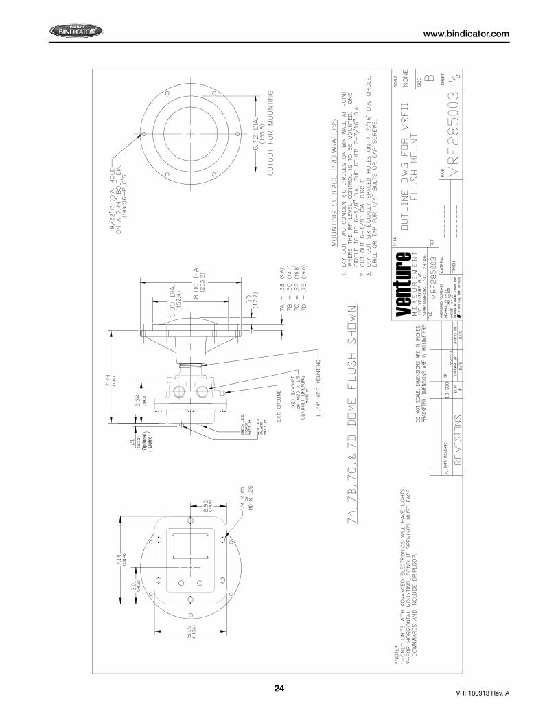
IX. DIMENSIONAL DRAWINGS
vent
ure

21
www.bindicator.com
VRF180913 Rev. A21

22VRF180913 Rev. A
www.bindicator.com
22
vent
ure

23
www.bindicator.com
VRF180913 Rev. A23
24VRF180913 Rev. A
www.bindicator.com
24
Optio
nal
Lights
vent
ure

25
www.bindicator.com
VRF180913 Rev. A25
Optio
nal
Lights

26VRF180913 Rev. A
www.bindicator.com
26
Notes

27
www.bindicator.com
VRF180913 Rev. A27
Notes

150 Venture Boulevard Spartanburg, SC 29306Tel: (800) 778-9242Fax: (864) [email protected]
2013 All rights reserved.All data subject to change without notice.
VRF180913 Rev. A