VOLUNTARY SERVICE CAMPAIGN 2018 PATHFINDER; …
16
1/16 Classification: Reference: Date: EC18-026 NTB18-072 October 24, 2018 VOLUNTARY SERVICE CAMPAIGN 2018 PATHFINDER; ELECTRIC INTAKE VALVE TIMING CONTROL MODULE REPROGRAMMING CAMPAIGN ID #: PC661 APPLIED VEHICLES: 2018 Pathfinder (R52) Check Service COMM or Dealer Business Systems (DBS) National Service History to confirm campaign eligibility. INTRODUCTION Nissan is conducting this voluntary service campaign on certain specific 2018 model year Pathfinder vehicles to reprogram the electric Intake Valve Timing (IVT) control module. This service will be performed at no charge to the customer for parts or labor. IDENTIFICATION NUMBER Nissan has assigned identification number PC661 to this campaign. This number must appear on all communication and documentation of any nature dealing with this campaign. DEALER RESPONSIBILITY Dealers are to repair vehicles falling within range of this campaign that enter the service department. This includes vehicles purchased from private parties, vehicles presented by transient (tourists) owners, and vehicles in a dealer’s inventory. Nissan Bulletins are intended for use by qualified technicians, not 'do-it-yourselfers'. Qualified technicians are properly trained individuals who have the equipment, tools, safety instruction, and know-how to do a job properly and safely. NOTE: If you believe that a described condition may apply to a particular vehicle, DO NOT assume that it does. See your Nissan dealer to determine if this applies to your vehicle.
Transcript of VOLUNTARY SERVICE CAMPAIGN 2018 PATHFINDER; …

1/16
Classification: Reference: Date:
EC18-026 NTB18-072 October 24, 2018
VOLUNTARY SERVICE CAMPAIGN 2018 PATHFINDER; ELECTRIC INTAKE VALVE TIMING
CONTROL MODULE REPROGRAMMING CAMPAIGN ID #: PC661 APPLIED VEHICLES: 2018 Pathfinder (R52)
Check Service COMM or Dealer Business Systems (DBS) National Service History to confirm campaign eligibility.
INTRODUCTION
Nissan is conducting this voluntary service campaign on certain specific 2018 model year Pathfinder vehicles to reprogram the electric Intake Valve Timing (IVT) control module. This service will be performed at no charge to the customer for parts or labor. IDENTIFICATION NUMBER
Nissan has assigned identification number PC661 to this campaign. This number must appear on all communication and documentation of any nature dealing with this campaign. DEALER RESPONSIBILITY
Dealers are to repair vehicles falling within range of this campaign that enter the service department. This includes vehicles purchased from private parties, vehicles presented by transient (tourists) owners, and vehicles in a dealer’s inventory. Nissan Bulletins are intended for use by qualified technicians, not 'do-it-yourselfers'. Qualified technicians are properly trained individuals who have the equipment, tools, safety instruction, and know-how to do a job properly and safely. NOTE: If you believe that a described condition may apply to a particular vehicle, DO NOT assume that it does. See your Nissan dealer to determine if this applies to your vehicle.
2/16 NTB18-072
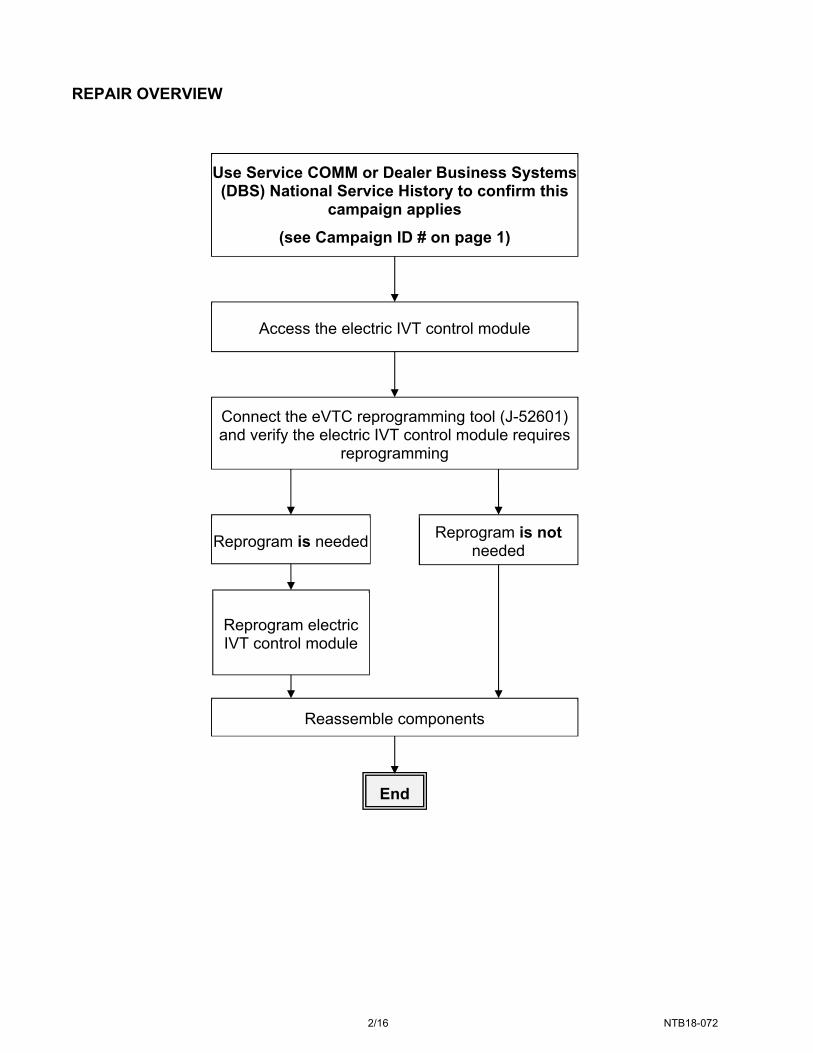
REPAIR OVERVIEW
Use Service COMM or Dealer Business Systems (DBS) National Service History to confirm this
campaign applies
(see Campaign ID # on page 1)
Connect the eVTC reprogramming tool (J-52601) and verify the electric IVT control module requires
reprogramming
Access the electric IVT control module
End
Reprogram is needed
Reassemble components
Reprogram is not needed
Reprogram electric IVT control module

3/16 NTB18-072
REQUIRED SPECIAL TOOLS
eVTC reprogramming kit (J-52601)
Each dealer has been shipped one eVTC reprogramming kit (J-52601).
Tool kit includes:
eVTC reprogramming tool.
Mini USB cable
Reprogramming harness
Additional tools can be obtained from Tech-Mate at 1-800-662-2001.
Figure 1
Connector “B”
eVTC reprogramming tool
Reprogramming harness
Connector “A”
4/16 NTB18-072
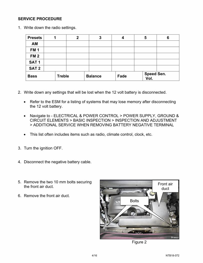
SERVICE PROCEDURE
1. Write down the radio settings.
Presets 1 2 3 4 5 6
AM
FM 1
FM 2
SAT 1
SAT 2
Bass Treble Balance Fade Speed Sen. Vol.
2. Write down any settings that will be lost when the 12 volt battery is disconnected.
Refer to the ESM for a listing of systems that may lose memory after disconnecting the 12 volt battery.
Navigate to - ELECTRICAL & POWER CONTROL > POWER SUPPLY, GROUND &
CIRCUIT ELEMENTS > BASIC INSPECTION > INSPECTION AND ADJUSTMENT > ADDITIONAL SERVICE WHEN REMOVING BATTERY NEGATIVE TERMINAL
This list often includes items such as radio, climate control, clock, etc.
3. Turn the ignition OFF. 4. Disconnect the negative battery cable.
Figure 2
5. Remove the two 10 mm bolts securing the front air duct.
6. Remove the front air duct. Bolts Bolts
Front air duct

5/16 NTB18-072
Figure 3
Figure 4
Figure 5
7. Remove the two 10 mm ground bolts shown in Figure 3.
Position the ground leads out of the
way (down to the left) to allow clearance to temporarily connect the eVTC reprogramming harness to the electric IVT control module.
8. Disconnect electric IVT control module’s
connector F106.
Depress locking tab while removing connector F106 from the electric IVT control module.
Once disconnected, temporarily position the connector to the left out of the way.
IMPORTANT: Use caution when connecting and disconnecting electrical connectors to prevent pin damage.
9. Disconnect the electric IVT control
module’s connector F105.
Depress locking tab (below the white locking lever) while lifting the white locking lever.
Once disconnected, temporarily
position the connector to the left out of the way.
IMPORTANT: Use caution when connecting and disconnecting electrical connectors to prevent pin damage.
Connector F106
Depress locking tab
HERE
Grounds Ground
bolts
Electric IVT control module
TCM
Connector F105 white
locking lever
Connector F106
disconnected

6/16 NTB18-072
Figure 6
Figure 7
10. Connect reprogramming connector “B”
to the electric IVT control module’s F105 location.
IMPORTANT: Use caution when connecting and disconnecting electrical connectors to prevent pin damage.
11. Connect reprogramming connector “A” to the electric IVT control module’s F106 location.
IMPORTANT: Use caution when connecting and disconnecting electrical connectors to prevent pin damage.
12. Connect the mini USB cable to your
CONSULT PC USB port. 13. Connect the A/C adapter to your
CONSULT PC. 14. Turn ON your CONSULT PC.
Reprogramming connector “A”
Reprogramming connector “B” (hidden under connector “A”
A/C adapter
Mini USB

7/16 NTB18-072
15. Open ASIST. 16. Open the “Specialty Tools” tab on the left side of the screen. 17. Select “PC661 & PC662 eIVT Reprogram” link. The screen shown in Figure 9 will
display.
Figure 8
18. Select “Read Revision” to view the electric IVT control module’s current software
version.
Figure 9
PC661 & PC662 eIVT Reprogram
8/16 NTB18-072
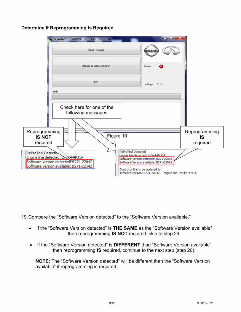
Determine If Reprogramming Is Required
Figure 10
19. Compare the “Software Version detected” to the “Software Version available.”
If the “Software Version detected” is THE SAME as the “Software Version available” then reprogramming IS NOT required, skip to step 24.
If the “Software Version detected” is DIFFERENT than “Software Version available”
then reprogramming IS required, continue to the next step (step 20). NOTE: The “Software Version detected” will be different than the “Software Version available” if reprogramming is required.
Check here for one of the following messages
Reprogramming IS
required
Reprogramming IS NOT required
9/16 NTB18-072
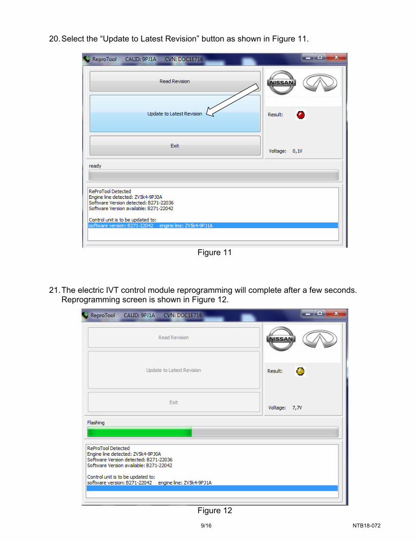
20. Select the “Update to Latest Revision” button as shown in Figure 11.
Figure 11
21. The electric IVT control module reprogramming will complete after a few seconds.
Reprogramming screen is shown in Figure 12.
Figure 12

10/16 NTB18-072
22. Verify the message “flash process finished successfully” as shown in Figure 13.
If this message does not display, refer to ERROR SCREENS on page 14.
23. Select “Exit.”
Figure 13
flash process finished
successfully

11/16 NTB18-072
Figure 14
Figure 15
24. Disconnect reprogramming connector
“A” and “B” from the electric IVT control module.
IMPORTANT: Use caution when connecting and disconnecting electrical connectors to prevent pin damage.
25. Connect the electric IVT control
module’s connector F105.
Fold the lever down to seat connector F105.
IMPORTANT: Use caution when connecting and disconnecting electrical connectors to prevent pin damage.
Reprogramming connector “A”
Reprogramming connector “B” (hidden under connector “A”
Connector F105 lever

12/16 NTB18-072
Figure 16
Figure 17
26. Connect the electric IVT control
module’s connector F106.
Listen for a “click” sound to verify connector F106 is properly seated.
IMPORTANT: Use caution when connecting and disconnecting electrical connectors to prevent pin damage.
27. Install ground bolts shown in Figure 17.
Torque bolts to 5.5 N•m (0.56 kg-m, 49 in-lb).
Connector F106
Grounds Grounds bolts

13/16 NTB18-072
Figure 18
31. Reset/reinitialize systems as needed.
Refer to the ESM for a listing of systems that require reset/initialization after reconnecting the 12V battery.
Navigate to - ELECTRICAL & POWER CONTROL > POWER SUPPLY, GROUND
& CIRCUIT ELEMENTS > BASIC INSPECTION > INSPECTION AND ADJUSTMENT > ADDITIONAL SERVICE WHEN REMOVING BATTERY NEGATIVE TERMINAL
This list often includes items such as radio, power windows, clock, sunroof, etc.
28. Install the front air duct. 29. Install the two 10 mm bolts securing the
front air duct.
Torque bolts to 5.5 N•m (0.56 kg-m, 49 in-lb).
30. Install the negative battery cable.
Bolts Bolts
Front air duct
14/16 NTB18-072
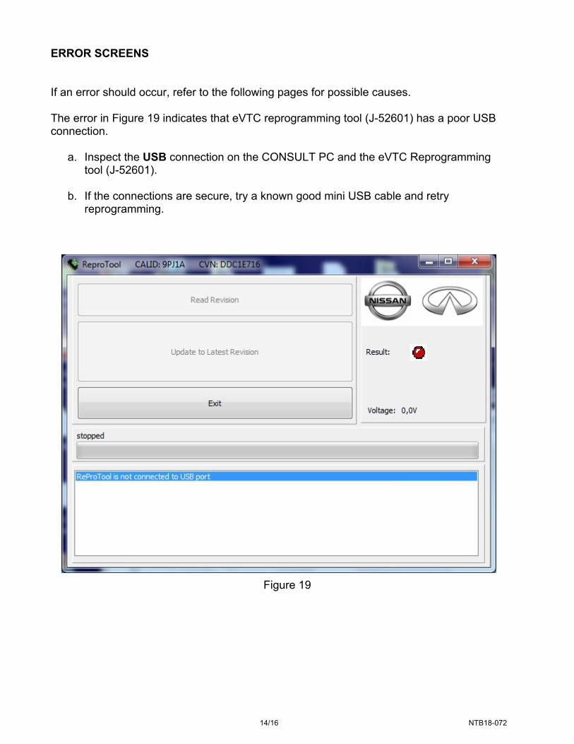
ERROR SCREENS
If an error should occur, refer to the following pages for possible causes. The error in Figure 19 indicates that eVTC reprogramming tool (J-52601) has a poor USB connection.
a. Inspect the USB connection on the CONSULT PC and the eVTC Reprogramming tool (J-52601).
b. If the connections are secure, try a known good mini USB cable and retry reprogramming.
Figure 19
15/16 NTB18-072
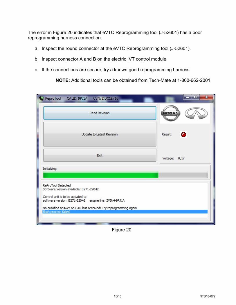
The error in Figure 20 indicates that eVTC Reprogramming tool (J-52601) has a poor reprogramming harness connection.
a. Inspect the round connector at the eVTC Reprogramming tool (J-52601).
b. Inspect connector A and B on the electric IVT control module.
c. If the connections are secure, try a known good reprogramming harness.
NOTE: Additional tools can be obtained from Tech-Mate at 1-800-662-2001.
Figure 20
16/16 NTB18-072
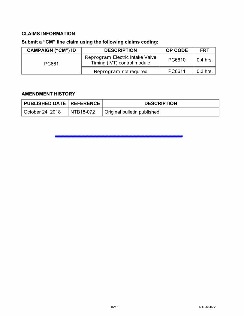
CLAIMS INFORMATION
Submit a “CM” line claim using the following claims coding:
CAMPAIGN (“CM”) ID DESCRIPTION OP CODE FRT
PC661 Reprogram Electric Intake Valve
Timing (IVT) control module PC6610 0.4 hrs.
Reprogram not required PC6611 0.3 hrs. AMENDMENT HISTORY
PUBLISHED DATE REFERENCE DESCRIPTION
October 24, 2018 NTB18-072 Original bulletin published