VOLUNTARY RECALL CAMPAIGN ENGINE SENSORS - Innova - Welcome to
25
1/25 Reference: Date: NTB03-124 December 19, 2003 VOLUNTARY RECALL CAMPAIGN ENGINE SENSORS CAMPAIGN I.D.# / NHTSA #: R3022 / 03V-345 APPLIED VEHICLES: 2000-03 Sentra (B15) 2002 Altima (L31) 2002-03 Maxima (A33) 2003 Murano (Z50) 2003 350Z (Z33) APPLIED VINS: Sentra 3N1*B*1**YL 000201 - 385976 3N1*B*1**1L 004135 - 525647 3N1*B*1**2L 550003 - 730181 3N1*B*1**3L 556548 – 730379 Altima 1N4AL11**2C100030 - 718759 1N4BL11**2C100029 - 718752 Maxima JN1DA*1**2T 000002 – 454681 JN1DA*1**3T 400002 - 515067 Murano JN8AZ08T*3W 100007 – 100032 JN8AZ08W*3W 200005 - 200071 350Z JN1AZ*4**3T 000001 - 100167 APPLIED ENGINES: QG18DE, QR25DE, VQ35DE NOTE: Use Service Comm. to confirm campaign eligibility. INTRODUCTION Nissan has determined that some 2000-2003 model year Nissan vehicles may have a defect which relates to motor vehicle safety. The engine might stop running while being driven if the crank position sensor or cam position sensor fails. This may also result in the “Service Engine Soon” light coming on or reduced engine power. If the engine stops running while driving, this could result in a crash without warning.
Transcript of VOLUNTARY RECALL CAMPAIGN ENGINE SENSORS - Innova - Welcome to

1/25
Reference: Date:
NTB03-124 December 19, 2003
VOLUNTARY RECALL CAMPAIGN ENGINE SENSORS
CAMPAIGN I.D.# / NHTSA #: R3022 / 03V-345
APPLIED VEHICLES: 2000-03 Sentra (B15)2002 Altima (L31)2002-03 Maxima (A33)2003 Murano (Z50)2003 350Z (Z33)
APPLIED VINS: Sentra3N1*B*1**YL 000201 - 3859763N1*B*1**1L 004135 - 5256473N1*B*1**2L 550003 - 7301813N1*B*1**3L 556548 – 730379
Altima1N4AL11**2C100030 - 7187591N4BL11**2C100029 - 718752
MaximaJN1DA*1**2T 000002 – 454681JN1DA*1**3T 400002 - 515067
MuranoJN8AZ08T*3W 100007 – 100032JN8AZ08W*3W 200005 - 200071
350ZJN1AZ*4**3T 000001 - 100167
APPLIED ENGINES: QG18DE, QR25DE, VQ35DE
NOTE: Use Service Comm. to confirm campaign eligibility.
INTRODUCTION
Nissan has determined that some 2000-2003 model year Nissan vehicles may have a defect which relates to motor vehicle safety. The engine might stop running while being driven if the crank position sensor or cam position sensor fails. This may also result in the “Service Engine Soon” light coming on or reduced engine power. If the engine stops running while driving, this could result in a crash without warning.

IDENTIFICATION NUMBER
Nissan has assigned identification number R3022 to this campaign. This number must appear on all communications and documentation of any nature dealing with this campaign. NUMBER OF VEHICLES POTENTIALLY AFFECTED
The number of vehicles potentially affected is approximately 572,000. DEALER RESPONSIBILITY
It is the retailer’s responsibility to check Service Comm for the campaign status on each vehicle falling within the range of this voluntary safety recall which for any reason enters the service department. This includes vehicles purchased from private parties or presented by transient (tourist) owners and vehicles in a dealer’s inventory. Federal law requires that new vehicles in dealer inventory which are the subject of a safety recall must be corrected prior to sale. Failure to do so can result in civil penalties by the National Highway Traffic Safety Administration. While federal law applies only to new vehicles, Nissan strongly encourages dealers to correct any used vehicles in their inventory before they are retailed.
2/25

SERVICE PROCEDURE
You will replace the following sensors: Crankshaft Position Sensor, Camshaft Position Sensor(s), and in some cases the Variable Timing Control Sensor(s). The service procedures are divided by engine ‘family’ and vehicle model (see Figure C, next page).
NOTE: Use Service Comm to confirm the vehicle is included in this campaign before performing the following procedure.
IMPORTANT
• There are three sensor kits associated with this campaign – one kit for each engine family (see Figure A, below).
• THE SENSORS IN EACH KIT ARE DIFFERENT. IT IS CRITICAL THAT EACH SENSOR BE INSTALLED IN THE CORRECT LOCATION. REFER TO FIGURE A (BELOW) AND THE ILLUSTRATIONS IN EACH REPAIR SECTION FOR SENSOR LOCATIONS.
• Each new sensor (within each kit) is contained in a bag. The bag is labeled with the Nissan part number. Keep the sensor in the bag until just before it is installed. The supplier part number is molded onto the face of the sensor. This number starts with “A29-”.
• The Crankshaft and Camshaft Position Sensors in Sensor Kits P/N 23731-4M528 and 23731-6N225 look the same. To help you tell the difference between these sensors, a white paint mark was added to the Crankshaft sensor (see Figure A).
• The old and new sensors may appear identical, therefore KEEP THEM SEPARATE.
• When disconnecting the vehicle harness connector* from the sensor(s); first PUSH the Release Button inward, then PULL the connector back (see Figure B, next page). NOTE: Do NOT pull on the wires when disconnecting the connector.
* The button for this connector is green and the connector body color is green or black.
Sensor Kits (Based on Engine Family)
Figure A
VQ35DE Sensor Kit P/N: 23731-AL627
QR25DE Sensor Kit P/N: 23731-6N225
QG18DE Sensor Kit P/N: 23731-4M528
TP030857
Crankshaft Position Sensor Nissan P/N: 23731-4M565 (on Bag)Supplier P/N: A29-630-BJ1 (on Sensor)
White Paint Mark
Camshaft Position Sensor (RH) *Nissan P/N: 23731-6J960 (on Bag)Supplier P/N: A29-640-CJ0 (on Sensor)
Camshaft Position Sensor (LH) Nissan P/N: 23731-AL670 (on Bag)Supplier P/N: A29-632-LJ0 (on Sensor)
Camshaft Position Sensor Nissan P/N: 23731-4M560 (on Bag)Supplier P/N: A29-630-BJ0 (on Sensor)
Variable Timing Control Sensor * Nissan P/N: 23731-6J965 (on Bag)Supplier P/N: A29-640-CJ1 (on Sensor)
White Paint Mark
Crankshaft Position Sensor Nissan P/N: 23731-AL660 (on Bag)Supplier P/N: A29-662-LJ0 (on Sensor)
* Not used on 2003 MY Sentra.
Crankshaft Position Sensor Nissan P/N: 23731-6N265 (on Bag)Supplier P/N: A29-660-AJ1 (on Sensor)
Camshaft Position Sensor Nissan P/N: 23731-6N260 (on Bag)Supplier P/N: A29-660-AJ0 (on Sensor)
Nissan P/N: 23731-6J906 (on Bag)Supplier P/N: A29-640-C20 (on Sensor)
OR
* This kit will contain either one of these sensors - not both.
3/25
Sensor Connector Release
Figure B TP030856
Green Release Button
PUSH RELEASE BUTTON INWARD PULL CONNECTOR BACK
Connector (may begreen or black)
NOTE: Do NOT pull on the wires when disconnecting the connector.
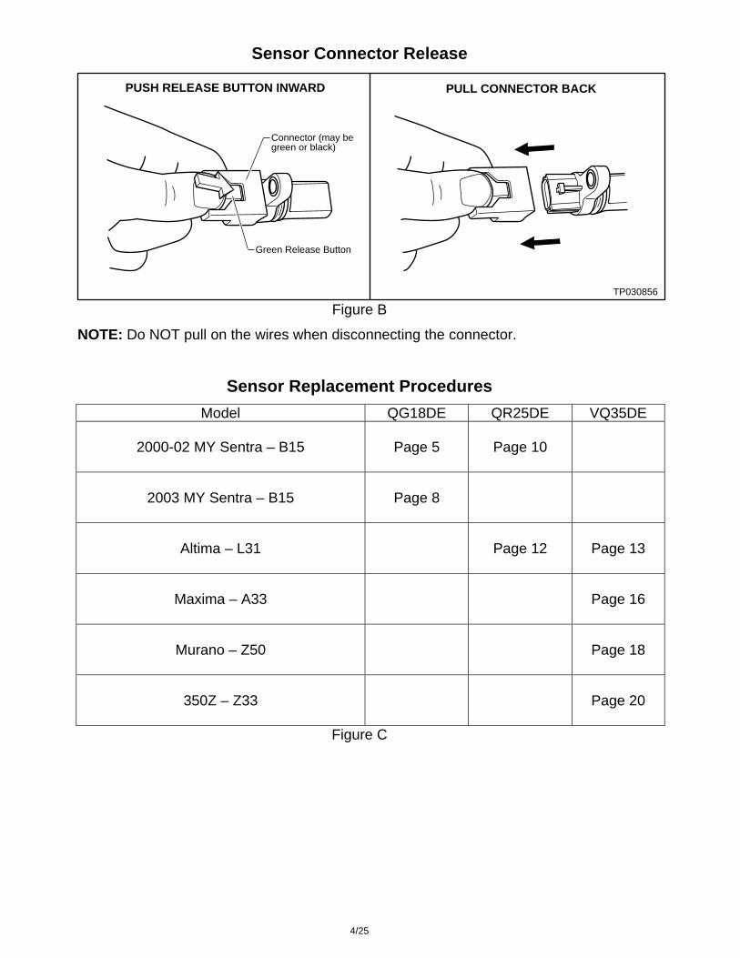
Sensor Replacement Procedures
Model QG18DE QR25DE VQ35DE
2000-02 MY Sentra – B15
Page 5
Page 10
2003 MY Sentra – B15
Page 8
Altima – L31
Page 12
Page 13
Maxima – A33
Page 16
Murano – Z50
Page 18
350Z – Z33
Page 20
Figure C
4/25

QG18DE Engine (Use Kit P/N 23731-4M528)
QG18DE Sensor Kit, P/N: 23731-4M528
TP030860White Paint Mark
Crankshaft Position Sensor Nissan P/N 23731-4M565 (on bag)Supplier P/N A29-630-BJ1 (on sensor)
Camshaft Position Sensor Nissan P/N 23731-4M560 (on bag)Supplier P/N A29-630-BJ0 (on sensor)
Variable Timing Control Sensor * Nissan P/N 23731-6J965 (on bag)Supplier P/N A29-640-CJ1 (on sensor)
* Not used on 2003 MY Sentra.
2000-02 MY Sentra (B15) IMPORTANT
• THE SENSORS IN THIS KIT ARE DIFFERENT. IT IS CRITICAL THAT EACH SENSOR BE INSTALLED IN THE CORRECT LOCATION. REFER TO “FIGURE A” AND THE ILLUSTRATIONS IN THIS REPAIR SECTION FOR SENSOR LOCATIONS.
• Each new sensor (within each kit) is contained in a bag. The bag is labeled with the Nissan part number. Keep the sensor in the bag until just before it is installed. The supplier part number is on the face of the sensor. This number starts with “A29-”.
• The Crankshaft and Camshaft Position Sensors in Sensor Kit P/N 23731-4M528 look the same. To help you tell the difference between these sensors, a white paint mark was added to the Crankshaft sensor (see illustration above).
• The old and new sensors may appear identical, therefore KEEP THEM SEPARATE.
Camshaft Position Sensor and Variable Timing Control Sensor Replacement
1. Record all radio station presets.
2. Disconnect the negative battery cable.
3. Locate the Camshaft Position Sensor and the Variable Timing Control Sensor (see Figure 1).
Figure 1 TP030770
Variable TimingControl SensorP/N: 23731-6J965(A29-640-CJ1)
Bolt
PassengerSide StrutTower
Bolt
No WhitePaint Mark No White
Paint Mark
Camshaft Position SensorP/N: 23731-4M560(A29-630-BJ0)
5/25

4. Disconnect the vehicle wire harness connectors from the sensors.
NOTE: If the connector will not release for you, see Figure B (if applicable).
5. Remove and save the bolts that hold the sensors in place.
Camshaft Position Sensor (P/N 27731-4M560 / A29-630-BJ0)
6. Remove the Camshaft Position Sensor with a pulling and twisting motion. Then, using a pair of pliers, break the connector on the OLD sensor so it cannot be reused.
7. Clean the hole that the old sensor was removed from.
8. Open the kit bag, remove the NEW sensor and apply a thin coat of clean engine oil to the o-ring on the new sensor.
9. Insert (until fully seated) the NEW sensor into the hole with a pushing and twisting motion, being careful not to damage the o-ring.
10. Re-install and tighten the sensor mounting bolt to 64 - 97 in-lb (7.2 – 11.0 N-m, 0.73 – 1.1 kg-m).
11. Re-connect the vehicle wire harness connector to the sensor.
Variable Timing Control Sensor (P/N 23731-6J965 / A29-640-CJ1)
12. Remove the Variable Timing Control Sensor with a pulling and twisting motion. Then, using a pair of pliers, break the connector on the OLD sensor so it cannot be reused.
13. Clean the hole that the old sensor was removed from.
14. Open the kit bag, remove the NEW sensor and apply a thin coat of clean engine oil to the o-ring on the new sensor.
15. Insert (until fully seated) the NEW sensor into the hole with a pushing and twisting motion, being careful not to damage the o-ring.
16. Re-install and tighten the sensor mounting bolt to 64 - 97 in-lb (7.2 – 11.0 N-m, 0.73 – 1.1 kg-m).
17. Re-connect the vehicle wire harness connector to the sensor.
6/25

Crankshaft Position Sensor* Replacement (P/N 23731-4M565 / A29-630-BJ1)
* This sensor has a white paint mark on it (see Figure 2).
1. Raise the vehicle on a hoist.
2. Locate the Crankshaft Position Sensor (see Figure 2).
Figure 2 TP030771
EngineOil Pan
Front
Bolt
Crankshaft Position SensorP/N: 23731-4M565(A29-630-BJ1)
Starter
With WhitePaint Mark
3. Disconnect the vehicle wire harness connector from the sensor.
NOTE: If the connector will not release for you, see Figure B (if applicable).
4. Remove and save the bolt that holds the sensor in place.
5. Remove the Crankshaft Position Sensor with a pulling and twisting motion. Then, using a pair of pliers, break the connector on the OLD sensor so it cannot be reused.
6. Clean the hole that the old sensor was removed from.
7. Open the kit bag, remove the NEW sensor and apply a thin coat of clean engine oil to the o-ring on the new sensor.
8. Insert (until fully seated) the NEW sensor into the hole with a pushing and twisting motion, being careful not to damage the o-ring.
9. Re-install and tighten the sensor mounting bolt to 64 - 97 in-lb (7.2 – 11.0 N-m, 0.73 – 1.1 kg-m).
10. Re-connect the vehicle wire harness connector to the sensor.
11. Lower the vehicle to the ground.
12. Reconnect the battery cable and reset the radio station presets and clock.
7/25
2003 MY Sentra (B15)
IMPORTANT
• THE SENSORS IN THIS KIT ARE DIFFERENT. IT IS CRITICAL THAT EACH SENSOR BE INSTALLED IN THE CORRECT LOCATION. REFER TO “FIGURE A” AND THE ILLUSTRATIONS IN THIS REPAIR SECTION FOR SENSOR LOCATIONS.
• Each new sensor (within each kit) is contained in a bag. The bag is labeled with the Nissan part number. Keep the sensor in the bag until just before it is installed. The supplier part number is on the face of the sensor. This number starts with “A29-”.
• The Crankshaft and Camshaft Position Sensors in Sensor Kit P/N 23731-4M528 look the same. To help you tell the difference between these sensors, a white paint mark was added to the Crankshaft sensor (see the illustration at the top of page 5).
• The old and new sensors may appear identical, therefore KEEP THEM SEPARATE.
• The Variable Timing Control Sensor (P/N 23731-6J965 / A29-640-CJ1) is NOT used on the 2003 MY Sentra.
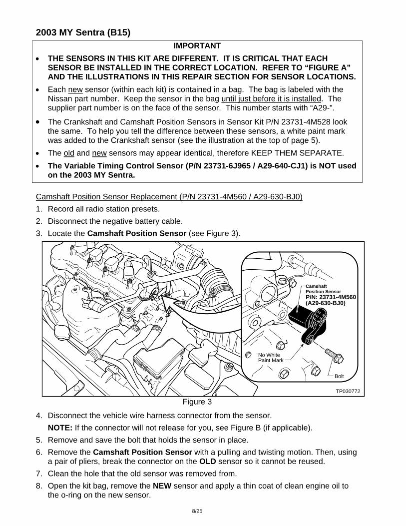
Camshaft Position Sensor Replacement (P/N 23731-4M560 / A29-630-BJ0)
1. Record all radio station presets.
2. Disconnect the negative battery cable.
3. Locate the Camshaft Position Sensor (see Figure 3).
Figure 3 TP030772
Camshaft Position SensorP/N: 23731-4M560(A29-630-BJ0)
Bolt
No WhitePaint Mark
4. Disconnect the vehicle wire harness connector from the sensor.
NOTE: If the connector will not release for you, see Figure B (if applicable).
5. Remove and save the bolt that holds the sensor in place.
6. Remove the Camshaft Position Sensor with a pulling and twisting motion. Then, using a pair of pliers, break the connector on the OLD sensor so it cannot be reused.
7. Clean the hole that the old sensor was removed from.
8. Open the kit bag, remove the NEW sensor and apply a thin coat of clean engine oil to the o-ring on the new sensor.
8/25
9. Insert (until fully seated) the NEW sensor into the hole with a pushing and twisting motion, being careful not to damage the o-ring.
10. Re-install and tighten the sensor mounting bolt to 64 - 97 in-lb (7.2 – 11.0 N-m, 0.73 – 1.1 kg-m).
11. Re-connect the vehicle wire harness connector to the sensor.
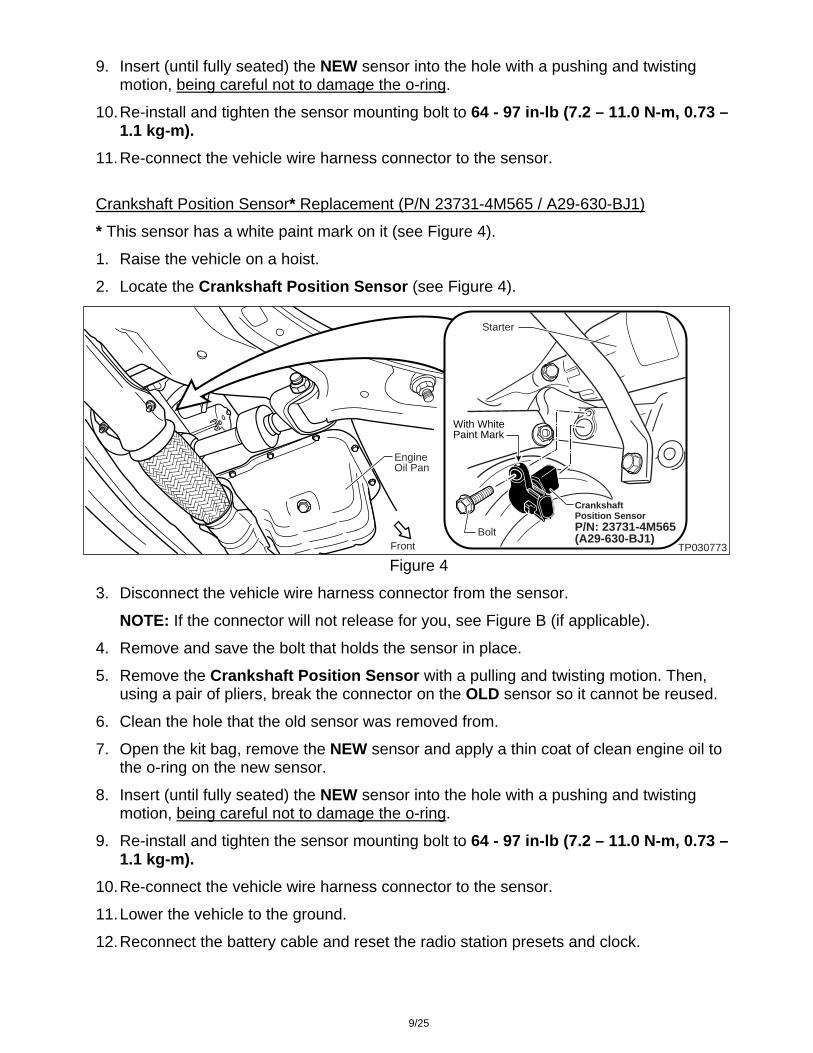
Crankshaft Position Sensor* Replacement (P/N 23731-4M565 / A29-630-BJ1)
* This sensor has a white paint mark on it (see Figure 4).
1. Raise the vehicle on a hoist.
2. Locate the Crankshaft Position Sensor (see Figure 4).
Figure 4 TP030773
Bolt
EngineOil Pan
Front
Crankshaft Position SensorP/N: 23731-4M565(A29-630-BJ1)
Starter
With WhitePaint Mark
3. Disconnect the vehicle wire harness connector from the sensor.
NOTE: If the connector will not release for you, see Figure B (if applicable).
4. Remove and save the bolt that holds the sensor in place.
5. Remove the Crankshaft Position Sensor with a pulling and twisting motion. Then, using a pair of pliers, break the connector on the OLD sensor so it cannot be reused.
6. Clean the hole that the old sensor was removed from.
7. Open the kit bag, remove the NEW sensor and apply a thin coat of clean engine oil to the o-ring on the new sensor.
8. Insert (until fully seated) the NEW sensor into the hole with a pushing and twisting motion, being careful not to damage the o-ring.
9. Re-install and tighten the sensor mounting bolt to 64 - 97 in-lb (7.2 – 11.0 N-m, 0.73 – 1.1 kg-m).
10. Re-connect the vehicle wire harness connector to the sensor.
11. Lower the vehicle to the ground.
12. Reconnect the battery cable and reset the radio station presets and clock.
9/25
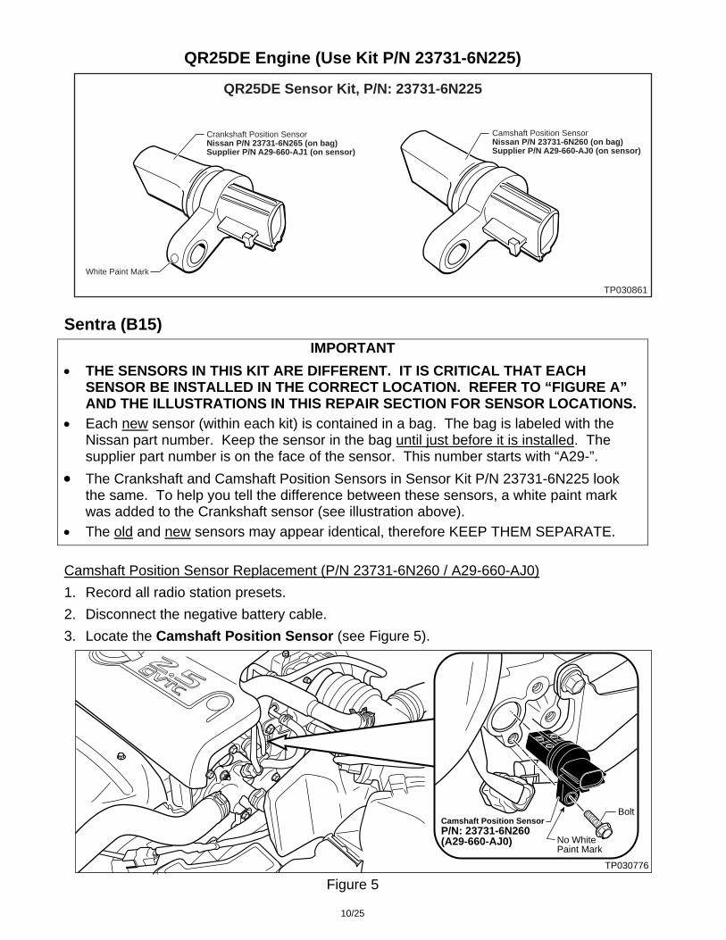
QR25DE Engine (Use Kit P/N 23731-6N225)
QR25DE Sensor Kit, P/N: 23731-6N225
TP030861
White Paint Mark
Crankshaft Position Sensor Nissan P/N 23731-6N265 (on bag)Supplier P/N A29-660-AJ1 (on sensor)
Camshaft Position Sensor Nissan P/N 23731-6N260 (on bag)Supplier P/N A29-660-AJ0 (on sensor)
Sentra (B15)
IMPORTANT
• THE SENSORS IN THIS KIT ARE DIFFERENT. IT IS CRITICAL THAT EACH SENSOR BE INSTALLED IN THE CORRECT LOCATION. REFER TO “FIGURE A” AND THE ILLUSTRATIONS IN THIS REPAIR SECTION FOR SENSOR LOCATIONS.
• Each new sensor (within each kit) is contained in a bag. The bag is labeled with the Nissan part number. Keep the sensor in the bag until just before it is installed. The supplier part number is on the face of the sensor. This number starts with “A29-”.
• The Crankshaft and Camshaft Position Sensors in Sensor Kit P/N 23731-6N225 look the same. To help you tell the difference between these sensors, a white paint mark was added to the Crankshaft sensor (see illustration above).
• The old and new sensors may appear identical, therefore KEEP THEM SEPARATE.
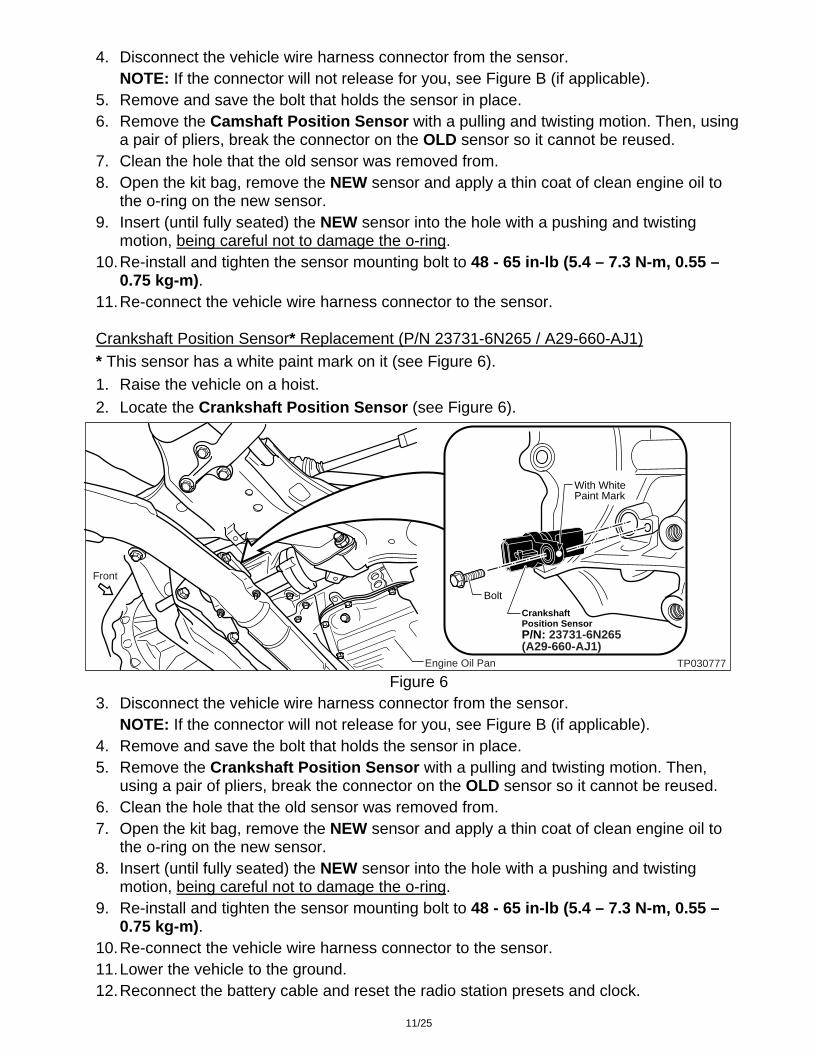
Camshaft Position Sensor Replacement (P/N 23731-6N260 / A29-660-AJ0)
1. Record all radio station presets.
2. Disconnect the negative battery cable.
3. Locate the Camshaft Position Sensor (see Figure 5).
Figure 5 TP030776
Camshaft Position SensorP/N: 23731-6N260(A29-660-AJ0)
Bolt
No WhitePaint Mark
10/25
4. Disconnect the vehicle wire harness connector from the sensor.
NOTE: If the connector will not release for you, see Figure B (if applicable).
5. Remove and save the bolt that holds the sensor in place.
6. Remove the Camshaft Position Sensor with a pulling and twisting motion. Then, using a pair of pliers, break the connector on the OLD sensor so it cannot be reused.
7. Clean the hole that the old sensor was removed from.
8. Open the kit bag, remove the NEW sensor and apply a thin coat of clean engine oil to the o-ring on the new sensor.
9. Insert (until fully seated) the NEW sensor into the hole with a pushing and twisting motion, being careful not to damage the o-ring.
10. Re-install and tighten the sensor mounting bolt to 48 - 65 in-lb (5.4 – 7.3 N-m, 0.55 – 0.75 kg-m).
11. Re-connect the vehicle wire harness connector to the sensor. Crankshaft Position Sensor* Replacement (P/N 23731-6N265 / A29-660-AJ1)
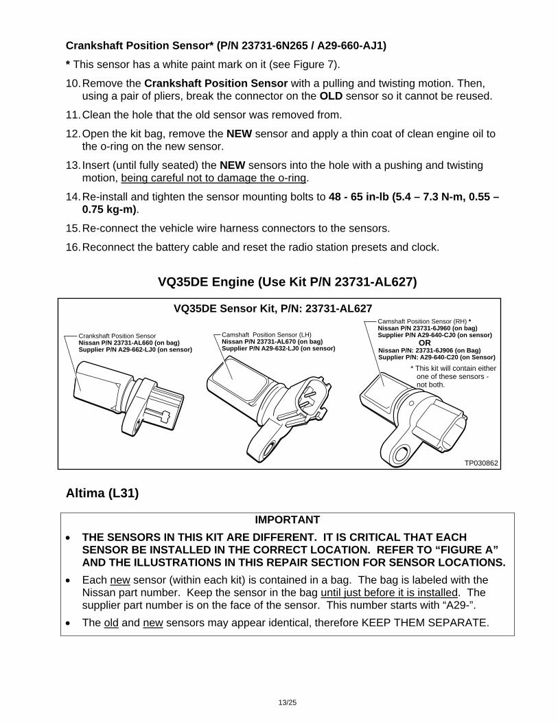
* This sensor has a white paint mark on it (see Figure 6).
1. Raise the vehicle on a hoist.
2. Locate the Crankshaft Position Sensor (see Figure 6).
Figure 6 TP030777
Front
Engine Oil Pan
Crankshaft Position SensorP/N: 23731-6N265(A29-660-AJ1)
Bolt
With WhitePaint Mark
3. Disconnect the vehicle wire harness connector from the sensor.
NOTE: If the connector will not release for you, see Figure B (if applicable).
4. Remove and save the bolt that holds the sensor in place.
5. Remove the Crankshaft Position Sensor with a pulling and twisting motion. Then, using a pair of pliers, break the connector on the OLD sensor so it cannot be reused.
6. Clean the hole that the old sensor was removed from.
7. Open the kit bag, remove the NEW sensor and apply a thin coat of clean engine oil to the o-ring on the new sensor.
8. Insert (until fully seated) the NEW sensor into the hole with a pushing and twisting motion, being careful not to damage the o-ring.
9. Re-install and tighten the sensor mounting bolt to 48 - 65 in-lb (5.4 – 7.3 N-m, 0.55 – 0.75 kg-m).
10. Re-connect the vehicle wire harness connector to the sensor.
11. Lower the vehicle to the ground.
12. Reconnect the battery cable and reset the radio station presets and clock.
11/25

Altima (L31)
IMPORTANT
• THE SENSORS IN THIS KIT ARE DIFFERENT. IT IS CRITICAL THAT EACH SENSOR BE INSTALLED IN THE CORRECT LOCATION. REFER TO “FIGURE A” AND THE ILLUSTRATIONS IN THIS REPAIR SECTION FOR SENSOR LOCATIONS.
• Each new sensor (within each kit) is contained in a bag. The bag is labeled with the Nissan part number. Keep the sensor in the bag until just before it is installed. The supplier part number is on the face of the sensor. This number starts with “A29-”.
• The Crankshaft and Camshaft Position Sensors in Sensor Kit P/N 23731-6N225 look the same. To help you tell the difference between these sensors, a white paint mark was added to the Crankshaft sensor (see the illustration at the top of page 10).
• The old and new sensors may appear identical, therefore KEEP THEM SEPARATE.
Camshaft & Crankshaft* Position Sensor Replacement
* This sensor has a white paint mark on it (see Figure 7).
1. Record all radio station presets.
2. Disconnect the negative battery cable.
3. Locate the Camshaft Position Sensor and Crankshaft Position Sensor (see Figure 7).
Figure 7 TP030877
Camshaft Position SensorP/N: 23731-6N260(A29-660-AJ0)
Bolt
No WhitePaint Mark
Crankshaft Position SensorP/N: 23731-6N265(A29-660-AJ1)
Bolt
With WhitePaint Mark
Lower RearEngine Block
4. Disconnect the vehicle wire harness connector from the sensors.
NOTE: If the connector will not release for you, see Figure B (if applicable).
5. Remove and save the bolt that holds the sensors in place.
Camshaft Position Sensor (P/N 23731-6N260 / A29-660-AJ0)
6. Remove the Camshaft Position Sensor with a pulling and twisting motion. Then, using a pair of pliers, break the connector on the OLD sensor so it cannot be reused.
7. Clean the hole that the old sensor was removed from.
8. Open the kit bag, remove the NEW sensor and apply a thin coat of clean engine oil to the o-ring on the new sensor.
9. Insert (until fully seated) the NEW sensors into the hole with a pushing and twisting motion, being careful not to damage the o-ring.
12/25
Crankshaft Position Sensor* (P/N 23731-6N265 / A29-660-AJ1)
* This sensor has a white paint mark on it (see Figure 7).
10. Remove the Crankshaft Position Sensor with a pulling and twisting motion. Then, using a pair of pliers, break the connector on the OLD sensor so it cannot be reused.
11. Clean the hole that the old sensor was removed from.
12. Open the kit bag, remove the NEW sensor and apply a thin coat of clean engine oil to the o-ring on the new sensor.
13. Insert (until fully seated) the NEW sensors into the hole with a pushing and twisting motion, being careful not to damage the o-ring.
14. Re-install and tighten the sensor mounting bolts to 48 - 65 in-lb (5.4 – 7.3 N-m, 0.55 – 0.75 kg-m).
15. Re-connect the vehicle wire harness connectors to the sensors.
16. Reconnect the battery cable and reset the radio station presets and clock.
VQ35DE Engine (Use Kit P/N 23731-AL627)
VQ35DE Sensor Kit, P/N: 23731-AL627
TP030862
Camshaft Position Sensor (RH) *Nissan P/N 23731-6J960 (on bag)Supplier P/N A29-640-CJ0 (on sensor)Camshaft Position Sensor (LH)
Nissan P/N 23731-AL670 (on bag)Supplier P/N A29-632-LJ0 (on sensor)
Crankshaft Position Sensor Nissan P/N 23731-AL660 (on bag)Supplier P/N A29-662-LJ0 (on sensor) Nissan P/N: 23731-6J906 (on Bag)
Supplier P/N: A29-640-C20 (on Sensor)
OR
* This kit will contain either one of these sensors - not both.
Altima (L31)
IMPORTANT
• THE SENSORS IN THIS KIT ARE DIFFERENT. IT IS CRITICAL THAT EACH SENSOR BE INSTALLED IN THE CORRECT LOCATION. REFER TO “FIGURE A” AND THE ILLUSTRATIONS IN THIS REPAIR SECTION FOR SENSOR LOCATIONS.
• Each new sensor (within each kit) is contained in a bag. The bag is labeled with the Nissan part number. Keep the sensor in the bag until just before it is installed. The supplier part number is on the face of the sensor. This number starts with “A29-”.
• The old and new sensors may appear identical, therefore KEEP THEM SEPARATE.
13/25

Camshaft Position Sensor Replacement (P/N 23731-AL670 / A29-632-LJ0 & 23731-6J960* / A29-640-CJ0)
* This sensor can be substituted with P/N 23731-6J906 / A29-640-C20.
1. Record all radio station presets.
2. Disconnect the negative battery cable.
3. Locate the Camshaft Position Sensors (see Figure 8).
Figure 8 TP030774
Bolt
Camshaft Position Sensor (LH)P/N 23731-AL670(A29-632-LJ0)
Bolt
No WhitePaint Mark
No WhitePaint Mark
Camshaft Position Sensor (RH)P/N 23731-6J960(A29-640-CJ0) orP/N 23731-6J906 (A29-640-C20)
4. Disconnect the vehicle wire harness connectors from the sensors.
NOTE: If the connector will not release for you, see Figure B (if applicable).
5. Remove and save the bolts that hold the sensors in place.
IMPORTANT: Perform the following steps on only ONE sensor at a time.
6. Remove the Camshaft Position Sensor with a pulling and twisting motion. Then, using a pair of pliers, break the connector on the OLD sensor so it cannot be reused.
7. Clean the hole that the old sensor was removed from.
8. Open the kit bag, remove the NEW sensor and apply a thin coat of clean engine oil to the o-ring on the new sensor.
9. Insert (until fully seated) the NEW sensor into the hole with a pushing and twisting motion, being careful not to damage the o-ring.
10. Re-install and tighten the sensor mounting bolt to 74 - 96 in-lb (8.4 – 10.8 N-m, 0.86 – 1.1 kg-m).
11. Re-connect the vehicle wire harness connectors to the sensors.
14/25

Crankshaft Position Sensor Replacement (P/N 23731-AL660 / A29-662-LJ0)
1. Raise the vehicle on a hoist.
2. Locate the Crankshaft Position Sensor (see Figure 9).
Figure 9 TP030775
Crankshaft Position SensorP/N 23731-AL660(A29-662-LJ0)
TransmissionOil Pan
TransmissionOil Pan
Bolt
FrontNo WhitePaint Mark
3. Disconnect the vehicle wire harness connector from the sensor.
NOTE: If the connector will not release for you, see Figure B (if applicable).
4. Remove and save the bolt that holds the sensor in place.
5. Remove the Crankshaft Position Sensor with a pulling and twisting motion. Then, using a pair of pliers, break the connector on the OLD sensor so it cannot be reused.
6. Clean the hole that the old sensor was removed from.
7. Open the kit bag, remove the NEW sensor and apply a thin coat of clean engine oil to the o-ring (if applicable) on the new sensor.
8. Insert (until fully seated) the NEW sensor into the hole with a pushing and twisting motion, being careful not to damage the o-ring.
9. Re-install and tighten the sensor mounting bolt to 74 - 96 in-lb (8.4 – 10.8 N-m, 0.86 – 1.1 kg-m).
10. Re-connect the vehicle wire harness connector to the sensor.
11. Lower the vehicle to the ground.
12. Reconnect the battery cable and reset the radio station presets and clock.
15/25

Maxima (A33)
IMPORTANT
• THE SENSORS IN THIS KIT ARE DIFFERENT. IT IS CRITICAL THAT EACH SENSOR BE INSTALLED IN THE CORRECT LOCATION. REFER TO “FIGURE A” AND THE ILLUSTRATIONS IN THIS REPAIR SECTION FOR SENSOR LOCATIONS.
• Each new sensor (within each kit) is contained in a bag. The bag is labeled with the Nissan part number. Keep the sensor in the bag until just before it is installed. The supplier part number is on the face of the sensor. This number starts with “A29-”.
• The old and new sensors may appear identical, therefore KEEP THEM SEPARATE.
Camshaft Position Sensor Replacement (P/N 23731-AL670 / A29-632-LJ0 & 23731-6J960* / A29-640-CJ0)
* This sensor can be substituted with P/N 23731-6J906 / A29-640-C20.
1. Record all radio station presets. 2. Disconnect the negative battery cable. 3. Locate the Camshaft Position Sensors (see Figure 10).
Figure 10 TP030789
Bolt
Camshaft Position Sensor (LH)P/N 23731-AL670(A29-632-LJ0)
No WhitePaint Mark
Bolt
No WhitePaint MarkCamshaft Position Sensor (RH)P/N 23731-6J960(A29-640-CJ0) orP/N 23731-6J906(A29-640-C20)
4. Disconnect the vehicle wire harness connectors from the sensors. NOTE: If the connector will not release for you, see Figure B (if applicable).
5. Remove and save the bolts that hold the sensors in place.
IMPORTANT: Perform the following steps on only ONE sensor at a time.
6. Remove the Camshaft Position Sensor with a pulling and twisting motion. Then, using a pair of pliers, break the connector on the OLD sensor so it cannot be reused.
7. Clean the hole that the old sensor was removed from.
8. Open the kit bag, remove the NEW sensor and apply a thin coat of clean engine oil to the o-ring on the new sensor.
9. Insert (until fully seated) the NEW sensor into the hole with a pushing and twisting motion, being careful not to damage the o-ring.
10. Re-install and tighten the sensor mounting bolt to 74 - 96 in-lb (8.4 – 10.8 N-m, 0.86 – 1.1 kg-m).
11. Re-connect the vehicle wire harness connectors to the sensors. 16/25

Crankshaft Position Sensor Replacement (P/N 23731-AL660 / A29-662-LJ0)
1. Raise the vehicle on a hoist.
2. Remove the Lower Engine Cover (see Figure 11).
3. Locate the Crankshaft Position
Sensor (see Figure 12).
TP030787
Lower Engine Cover(Remove)
TransmissionOil Pan
Front
Figure 11
TP030788
Crankshaft Position SensorP/N 23731-AL660(A29-662-LJ0)
Trans-missionOil Pan
Bolt
Front
No WhitePaint Mark
Figure 12
4. Disconnect the vehicle wire harness connector from the sensor.
NOTE: If the connector will not release for you, see Figure B (if applicable).
5. Remove and save the bolt that holds the sensor in place.
6. Remove the Crankshaft Position Sensor with a pulling and twisting motion. Then, using a pair of pliers, break the connector on the OLD sensor so it cannot be reused.
7. Clean the hole that the old sensor was removed from.
8. Open the kit bag, remove the NEW sensor and apply a thin coat of clean engine oil to the o-ring (if applicable) on the new sensor.
9. Insert (until fully seated) the NEW sensor into the hole with a pushing and twisting motion, being careful not to damage the o-ring.
10. Re-install and tighten the sensor mounting bolt to 74 - 96 in-lb (8.4 – 10.8 N-m, 0.86 – 1.1 kg-m).
11. Re-connect the vehicle wire harness connector to the sensor.
12. Re-install the Lower Engine Cover. 13. Lower the vehicle to the ground. 14. Reconnect the battery cable and reset the radio station presets and clock.
17/25

Murano (Z50)
IMPORTANT
• THE SENSORS IN THIS KIT ARE DIFFERENT. IT IS CRITICAL THAT EACH SENSOR BE INSTALLED IN THE CORRECT LOCATION. REFER TO “FIGURE A” AND THE ILLUSTRATIONS IN THIS REPAIR SECTION FOR SENSOR LOCATIONS.
• Each new sensor (within each kit) is contained in a bag. The bag is labeled with the Nissan part number. Keep the sensor in the bag until just before it is installed. The supplier part number is on the face of the sensor. This number starts with “A29-”.
• The old and new sensors may appear identical, therefore KEEP THEM SEPARATE.
Camshaft Position Sensor Replacement (P/N 23731-AL670 / A29-632-LJ0 & 23731-6J960* / A29-640-CJ0)
* This sensor can be substituted with P/N 23731-6J906 / A29-640-C20.
1. Record all radio station presets.
2. Disconnect the negative battery cable.
3. Locate the Camshaft Position Sensors (see Figure 13).
Figure 13 TP030767
Bolt
Camshaft Position Sensor (LH)P/N 23731-AL670(A29-632-LJ0)
Camshaft Position Sensor (RH)P/N 23731-6J960(A29-640-CJ0) orP/N 23731-6J906(A29-640-C20)
BoltNo WhitePaint Mark
No WhitePaint Mark
4. Disconnect the vehicle wire harness connectors from the sensors.
NOTE: If the connector will not release for you, see Figure B (if applicable).
5. Remove and save the bolts that hold the sensors in place.
IMPORTANT: Perform the following steps on only ONE sensor at a time.
6. Remove the Camshaft Position Sensor with a pulling and twisting motion. Then, using a pair of pliers, break the connector on the OLD sensor so it cannot be reused.
7. Clean the hole that the old sensor was removed from.
8. Open the kit bag, remove the NEW sensor and apply a thin coat of clean engine oil to the o-ring on the new sensor.
18/25

9. Insert (until fully seated) the NEW sensor into the hole with a pushing and twisting motion, being careful not to damage the o-ring.
10. Re-install and tighten the sensor mounting bolt to 74 - 96 in-lb (8.4 – 10.8 N-m, 0.86 – 1.1 kg-m).
11. Re-connect the vehicle wire harness connectors to the sensors.
Crankshaft Position Sensor Replacement (P/N 23731-AL660 / A29-662-LJ0)
1. Raise the vehicle on a hoist.
2. Locate the Crankshaft Position Sensor (see Figure 14).
Figure 14 TP030768
Crankshaft Position SensorP/N 23731-AL660(A29-662-LJ0)
Bolt
Front
No WhitePaint Mark
3. Disconnect the vehicle wire harness connector from the sensor.
NOTE: If the connector will not release for you, see Figure B (if applicable).
4. Remove and save the bolt that holds the sensor in place.
5. Remove the Crankshaft Position Sensor with a pulling and twisting motion. Then, using a pair of pliers, break the connector on the OLD sensor so it cannot be reused.
6. Clean the hole that the old sensor was removed from.
7. Open the kit bag, remove the NEW sensor and apply a thin coat of clean engine oil to the o-ring (if applicable) on the new sensor.
8. Insert (until fully seated) the NEW sensor into the hole with a pushing and twisting motion, being careful not to damage the o-ring.
9. Re-install and tighten the sensor mounting bolt to 74 - 96 in-lb (8.4 – 10.8 N-m, 0.86 – 1.1 kg-m).
10. Re-connect the vehicle wire harness connector to the sensor.
11. Lower the vehicle to the ground.
12. Reconnect the battery cable and reset the radio station presets and clock.
19/25
350Z (Z33)
IMPORTANT
• THE SENSORS IN THIS KIT ARE DIFFERENT. IT IS CRITICAL THAT EACH SENSOR BE INSTALLED IN THE CORRECT LOCATION. REFER TO “FIGURE A” AND THE ILLUSTRATIONS IN THIS REPAIR SECTION FOR SENSOR LOCATIONS.
• Each new sensor (within each kit) is contained in a bag. The bag is labeled with the Nissan part number. Keep the sensor in the bag until just before it is installed. The supplier part number is on the face of the sensor. This number starts with “A29-”.
• The old and new sensors may appear identical, therefore KEEP THEM SEPARATE.
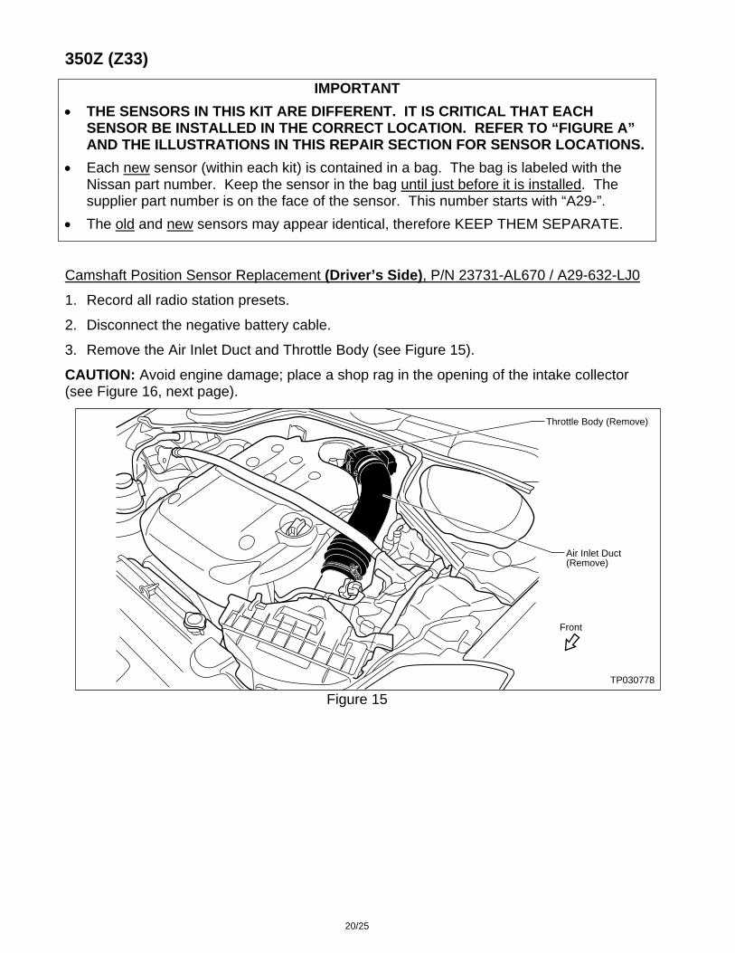
Camshaft Position Sensor Replacement (Driver’s Side), P/N 23731-AL670 / A29-632-LJ0
1. Record all radio station presets.
2. Disconnect the negative battery cable.
3. Remove the Air Inlet Duct and Throttle Body (see Figure 15).
CAUTION: Avoid engine damage; place a shop rag in the opening of the intake collector (see Figure 16, next page).
Figure 15 TP030778
Air Inlet Duct(Remove)
Throttle Body (Remove)
Front
20/25

4. Locate the driver’s side (LH) Camshaft Position Sensor (see Figure 16).
Figure 16 TP030779
Front
Camshaft Position Sensor (LH)P/N 23731-AL670(A29-632-LJ0)
Intake Collector
Bolt
No WhitePaint Mark
Shop Rag
5. Disconnect the vehicle wire harness connector from the sensor.
NOTE: If the connector will not release for you, see Figure B (if applicable).
6. Remove and save the bolt that holds the sensor in place.
7. Remove the Camshaft Position Sensor with a pulling and twisting motion. Then, using a pair of pliers, break the connector on the OLD sensor so it cannot be reused.
8. Clean the hole that the old sensor was removed from.
9. Open the kit bag, remove the NEW sensor and apply a thin coat of clean engine oil to the o-ring on the new sensor.
10. Insert (until fully seated) the NEW sensor into the hole with a pushing and twisting motion, being careful not to damage the o-ring.
11. Re-install and tighten the sensor mounting bolt to 74 - 96 in-lb (8.4 – 10.8 N-m, 0.86 – 1.1 kg-m).
12. Re-connect the vehicle wire harness connector to the sensor.
21/25

Camshaft Position Sensor Replacement (Pass. Side), P/N 23731-6J960* / A29-640-CJ0
* This sensor can be substituted with P/N 23731-6J906 / A29-640-C20.
1. Locate the passenger side (RH) Camshaft Position Sensor (see Figure 17).
Figure 17 TP030780
Camshaft Position Sensor (RH)P/N 23731-6J960(A29-640-CJ0) orP/N 23731-6J906(A29-640-C20)
BoltFront
No WhitePaint Mark
IntakeCollector
2. Disconnect the vehicle wire harness connector from the sensor.
NOTE: If the connector will not release for you, see Figure B (if applicable).
3. Remove and save the bolt that holds the sensor in place.
4. Remove the Camshaft Position Sensor with a pulling and twisting motion. Then, using a pair of pliers, break the connector on the OLD sensor so it cannot be reused.
5. Clean the hole that the old sensor was removed from.
6. Open the kit bag, remove the NEW sensor and apply a thin coat of clean engine oil to the o-ring on the new sensor.
7. Insert (until fully seated) the NEW sensor into the hole with a pushing and twisting motion, being careful not to damage the o-ring.
8. Re-install and tighten the sensor mounting bolt to 74 - 96 in-lb (8.4 – 10.8 N-m, 0.86 – 1.1 kg-m).
9. Re-connect the vehicle wire harness connector to the sensor.
10. Remove the shop rag from the intake collector opening. Then re-install the Throttle Body using the new gasket (see Parts Information). Tighten the Throttle Body screws to 64 – 86 in-lb (7.2 – 9.7 N-m, 0.73 – 0.99 kg-m).
11. Re-install the Air Inlet Duct.
22/25
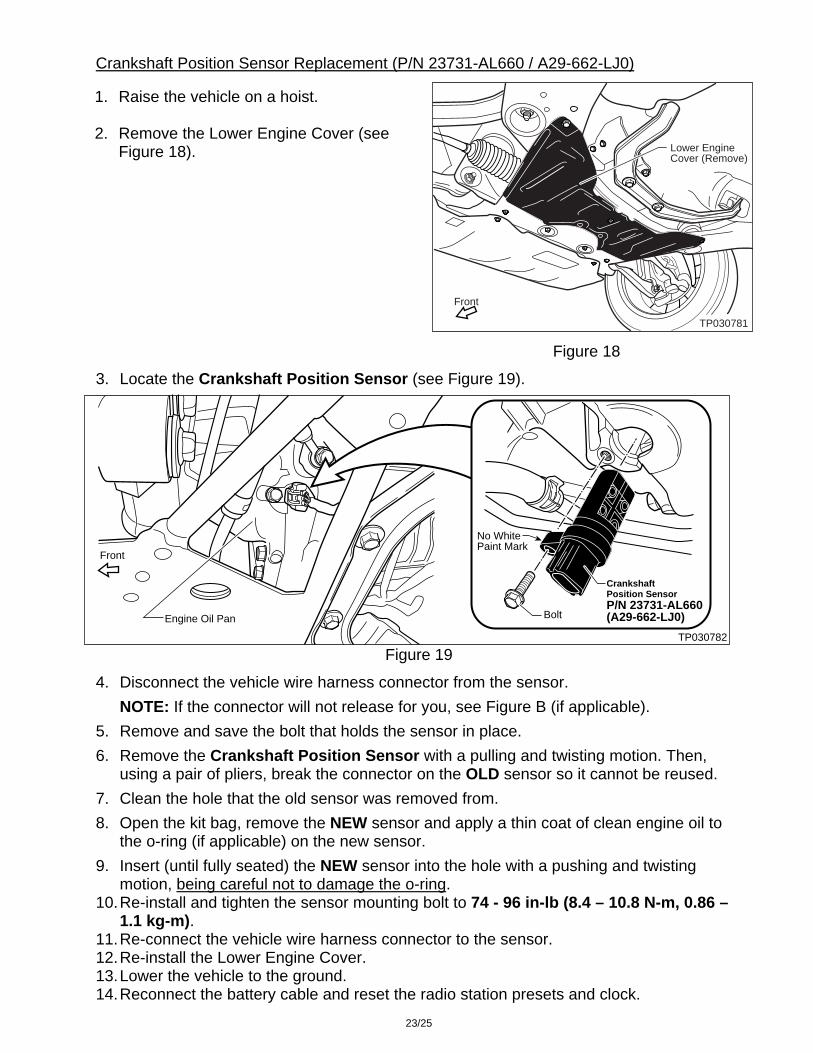
Crankshaft Position Sensor Replacement (P/N 23731-AL660 / A29-662-LJ0)
TP030781
Lower EngineCover (Remove)
Front
Figure 18
1. Raise the vehicle on a hoist.
2. Remove the Lower Engine Cover (see Figure 18).
3. Locate the Crankshaft Position Sensor (see Figure 19).
Figure 19 TP030782
Crankshaft Position SensorP/N 23731-AL660(A29-662-LJ0)Bolt
Front
Engine Oil Pan
No WhitePaint Mark
4. Disconnect the vehicle wire harness connector from the sensor.
NOTE: If the connector will not release for you, see Figure B (if applicable).
5. Remove and save the bolt that holds the sensor in place.
6. Remove the Crankshaft Position Sensor with a pulling and twisting motion. Then, using a pair of pliers, break the connector on the OLD sensor so it cannot be reused.
7. Clean the hole that the old sensor was removed from.
8. Open the kit bag, remove the NEW sensor and apply a thin coat of clean engine oil to the o-ring (if applicable) on the new sensor.
9. Insert (until fully seated) the NEW sensor into the hole with a pushing and twisting motion, being careful not to damage the o-ring.
10. Re-install and tighten the sensor mounting bolt to 74 - 96 in-lb (8.4 – 10.8 N-m, 0.86 – 1.1 kg-m).
11. Re-connect the vehicle wire harness connector to the sensor. 12. Re-install the Lower Engine Cover. 13. Lower the vehicle to the ground. 14. Reconnect the battery cable and reset the radio station presets and clock.
23/25
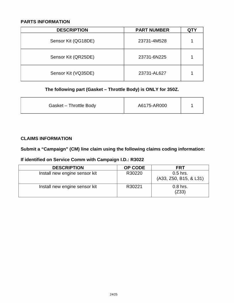
PARTS INFORMATION
DESCRIPTION PART NUMBER QTY
Sensor Kit (QG18DE) 23731-4M528 1
Sensor Kit (QR25DE) 23731-6N225 1
Sensor Kit (VQ35DE) 23731-AL627 1
The following part (Gasket – Throttle Body) is ONLY for 350Z.
Gasket – Throttle Body A6175-AR000 1
CLAIMS INFORMATION Submit a “Campaign” (CM) line claim using the following claims coding information: If identified on Service Comm with Campaign I.D.: R3022
DESCRIPTION OP CODE FRT Install new engine sensor kit R30220 0.5 hrs.
(A33, Z50, B15, & L31)
Install new engine sensor kit R30221 0.8 hrs. (Z33)
24/25
OWNER’S LETTER
Dear Nissan owner: This notice is sent to you in accordance with the requirements of the National Traffic and Motor Vehicle Safety Act. Nissan has decided that a defect which relates to motor vehicle safety exists in some 2000-2003 model year Nissan vehicles. Our records indicate that you own the Nissan vehicle identified by the Vehicle Identification Number on the cover of this notice. Reason for Recall
On some 2000-2003 model year Nissan vehicles, there is a possibility that the engine might stop running while being driven if the crank position sensor fails. This may also result in the “Service Engine Soon” light coming on or reduced engine power. If the engine stops running while driving, this could result in a crash without warning. What Nissan Will Do
In order to prevent this incident from occurring, your Nissan dealer will replace the crank position sensors. This free service should take about one hour to complete, but your Nissan dealer may require your vehicle for a longer period of time based upon their work schedule, or parts availability. What You Should Do
Contact your Nissan dealer at your earliest convenience in order to arrange an appointment to have your vehicle repaired. If the “Service Engine Soon” light comes on, contact your dealer as soon as possible to have your vehicle inspected. Please bring this notice with you when you keep your service appointment. Instructions have been sent to your Nissan dealer. If the dealer fails, or is unable to make the necessary repairs free of charge, you may contact the National Consumer Affairs Office, Nissan North America, Inc. at P.O. Box 191, Gardena, California 90248-0191. The toll free number is 1-800-NISSAN1 (1-800-647-7261). If you reside in Hawaii, please call 1-808-836-0888. You may also contact the Administrator of the National Highway Traffic Safety Administration, 400 Seventh Street SW, Washington, D.C. 20590 or call the toll free Safety Hotline at (888) 327-4236.
If you have paid to have a crank position sensor replaced prior to this campaign, you may be eligible for reimbursement of the related expense. Contact Nissan Consumer Affairs at the numbers listed above for additional information on how to obtain a reimbursement.
Federal law requires that any vehicle lessor receiving this recall notice must forward a copy of this notice to the lessee within ten days.
Thank you for your cooperation. We are indeed sorry for any inconvenience this may cause you.
25/25