
VOLUMETRIC BLENDING SYSTEM OPERATION MANUALlaycopro.com/Equipment Documents/Complete System...
26
1 VOLUMETRIC BLENDING SYSTEM OPERATION MANUAL 12285 E. MAIN ST. MARSHALL, IL 62441 PHONE: 217-826-6352 FAX: 217-826-8551 WEB SITE: www.yargus.com
Transcript of VOLUMETRIC BLENDING SYSTEM OPERATION MANUALlaycopro.com/Equipment Documents/Complete System...
1
VOLUMETRIC BLENDING SYSTEM
OPERATION MANUAL
12285 E. MAIN ST.
MARSHALL, IL 62441
PHONE: 217-826-6352
FAX: 217-826-8551
WEB SITE: www.yargus.com

2
OPENING SCREEN
The OPENING SCREEN is the screen that the PLC system boots up to if ever a power cycle
was to occur. From here you can navigate to any location in the system. At the bottom of this screen
and all other screens is the menu bar. Most of the operations will be performed through the
SYSTEM MENU and VALVE MENU buttons. A description of each button will follow later in the
manual.

3
SYSTEM MENU button
The SYSTEM MENU button groups system related screens

4
DISPLAY SETTINGS
Here you can adjust the display brightness, activate a screen saver and set the system time
and date. For brightness control you would just arrow up or arrow down. The screen saver is
activated by pressing its button. The time and date can be set by pressing the SET TIME/DATE
button and follow the format shown.

5
BLEND ENTRY
Blend Entry begins the process of running a blend. Here you would enter the weight of each
chemical in each hopper. The name of each chemical is listed above the hopper weight entry button.
Entering actual weight per each hopper would be the method used when not running a saved ratio
blend. After you enter in all desired weights for each chemical, you would then press the RUN
BLEND button. Any alarms that may occur will appear towards the bottom of the screen. For
instance if weight is entered for a hopper and that hopper does not have its VOLUME CONSTANT,
BULK DENSITY, or VALVE DELAY set, an alarm will appear. These three characteristics must be
set before running a hopper. The numeric values shown at each hopper is the valve RPM speed at
which the valve will run. As the weight changes for each valve, these values may also change.
75RPM is the fastest and 8RPM is the slowest speed a valve can start at.

6
RUN BLEND
The RUN BLEND screen can only be accessed through the Blend Entry screen when weight has
been entered in one or more valves. Here only the hopper or hoppers with blend weight will appear.
Also the run-time is also calculated and displayed. The color scheme for each valve is as follows:
green indicated the valve is in DW mode, Silver indicates volumetric mode, and orange indicates
impregnation mode. Once the run-time is displayed and the START button, the blend will start when
the operator presses the START button. After a blend is started, this same button becomes the
PAUSE button for pausing blends. Then START again to re-start. After a blend has started a
CANCEL button appears which can be used to cancel a blend completely forcing.

7
SPOUT LOCATION
The SPOUT LOCATION screen can also be accessed through the RUN BLEND screen.
Here you just select which spout you want your blend to travel through. The current location of the
SPOUT is shown in the top right corner. The SP1,SP2…names can be changed to the users liking of
14 characters or less.

8
LOADOUT DELAYS
The LOADOUT DELAY should be set to a high enough number so at the end of a blend all
product has been cleaned out of the conveyance systems. This would include all conveying sections
after the under bin. The delay time is in seconds.

9
I/O SCREEN
The I/O SCREEN is mainly used for troubleshooting and/or maintenance. Here you can view
all input and output status.

10
VALVE MENU button
The VALVE MENU button groups valve related screens.

11
VOLUME CONSTANT
VOLUME CONSTANT screen is used to set the volume constant of each valve. In a DW
system this value can be self adjusted or calibrated at the end of each blend for more precise weight
loss accuracy.
12
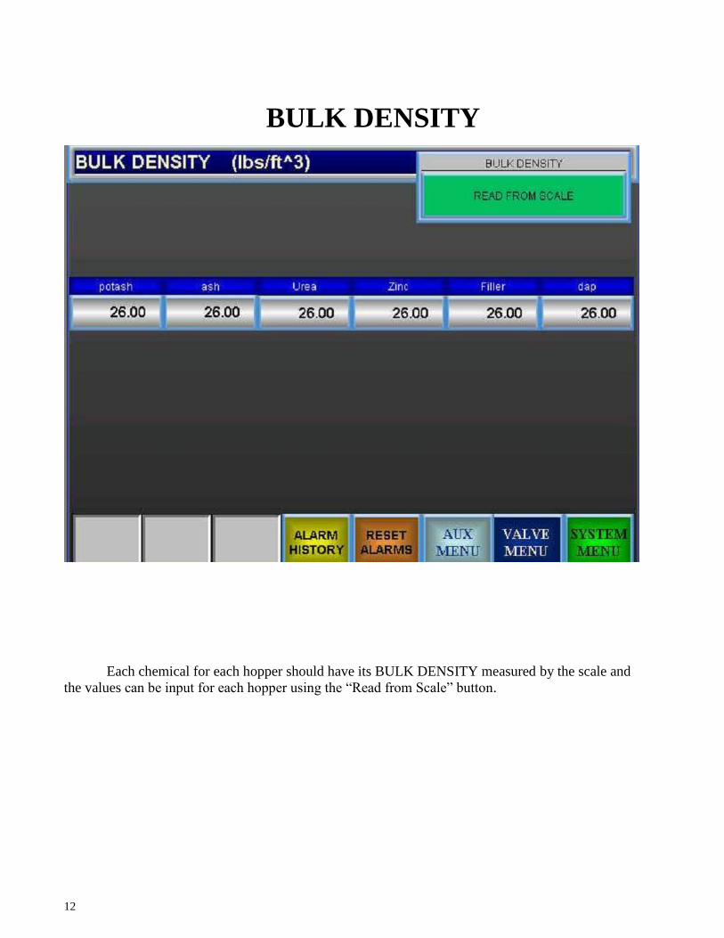
BULK DENSITY
Each chemical for each hopper should have its BULK DENSITY measured by the scale and
the values can be input for each hopper using the “Read from Scale” button.

13
EMPTY HOPPERS
EMPTY HOPPER screen is used for cleaning out a hopper in order to fill that hopper with a
different chemical. There is no system feedback when emptying a hopper. Once you press the button
the hopper will run until you press the button again to stop it.

14
VALVE DELAYS
The value entered here for each DELAY VALVE is in seconds and should be a measured
time of how long it takes for the product to get from one valve to the next valve in front of it. This
run-time can be calculated or simply entered by using a stop watch. A DELAY VALUE cannot be
equal to zero. If a zero is needed a value of .01 is sufficient. The VALVE DELAY time reference is
the end of the under bin. This is referred to as the focal point. Start out by measuring the time the
chemical of the last valve (closest to the focal point) takes to reach the focal point. After this then
measure the time the chemical of the next valve back (second to last) takes to reach the last valve.
Repeat this process until you reach the first valve.
15
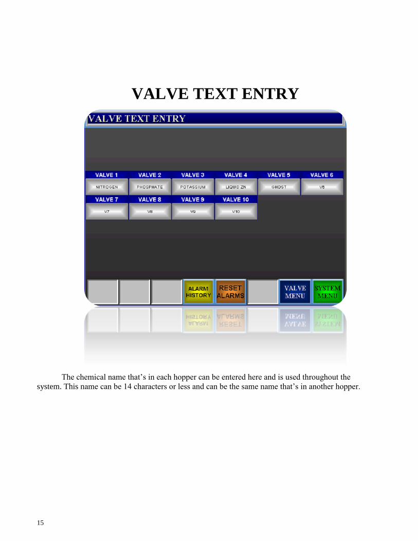
VALVE TEXT ENTRY
The chemical name that’s in each hopper can be entered here and is used throughout the
system. This name can be 14 characters or less and can be the same name that’s in another hopper.

16
BINDICATORS
BRIDGED INDICATOR
The bridged indicator is right above the discharge of the rotary valve on the back. This
sensor is to sense a bridged condition. As soon as this condition is detected, the system
goes into an emergency shutdown condition. All rotary valves as well as the main auger
will shut down immediately. This prevents the batch from being corrupted and maintains
the integrity of the batch. To fix this condition, the operator must rap the side of the bin
with a rubber mallet. When the bridge has been broken pressing the RESET ALARMS
button can reset the Alarm. Once reset, the START button can be pressed to resume the
batch cycle.
ROTARY VALVE INDICATOR
Each VFD is equipped with a relay that tells the system whether or not the VFD is running.
If the VFD overloads, or shuts down for any reason, the system will stop. If this happens,
turn off the VFD, wait for it to power down, then turn it back on to reset it. Following this,
press the “Reset Alarms” button on the touch screen. Once reset, the START button can be
pressed to resume the batch cycle.
UNDER BIN AUGER INDICATOR
The Under Bin auger is equipped with a Zero Speed switch, which senses if the auger is
turning when the system is running. If for some reason the auger stops during a batch cycle,
the system will go into an emergency shutdown. Once the problem has been corrected, and
the Alarm has been reset on the main panel, the START button can be pressed to resume
the batch cycle.
LOAD OUT CONVEYOR INDICATOR
The Load out Conveyor is equipped with a Zero Speed switch, which senses if the auger is
turning when the system is running. If for some reason the Conveyor stops during a batch
cycle, the system will go into an emergency shutdown. Once the problem has been
corrected, and the Alarm has been reset on the main panel, the START button can be
pressed to resume the batch cycle.

17
VALVE ALARMS
An * denotes alarm will not stop a run or prevent a blend from being made
ALARM DIAGNOSTIC SOLUTION
Standard Alarms
Hopper Bridged Indicates that there is no material that
is ready to be distributed by the valve.
Usually caused by an air pocket or
clumped/stuck material to hopper or
hopper has run empty.
Low Level Hopper *
Material in hopper is below sensor
level
Fill hopper before it runs out of
product
Hopper “x” Valve Motion Valve is not turning
Something is preventing valve from
moving or is a VFD issue
Blend Ratio is too rich
One or more weights is too low or
high
VFD's cannot turn valves slow enough
to compensate for weight, adjust
blend
Emergency Stop Emergency Stop Button was pressed. Pull out E-stop and reset alarms
BE Pressure Switch Spout is plugged Unplug the spout and reset alarms
Bucket Elevator Zero Speed
Underbin Zero Speed
Loadout Zero Speed
Zero speed switch detects no motion
or not enough RPM's
Make sure conveyor is
running/running at required speed,
make sure that Zero Speed Switch has
not fallen out of calibration

18
12285 EAST MAIN STREET
MARSHALL, IL 62441
217-826-6352
WWW.YARGUS.COM
VOLUMETRIC AND
DW MANUAL
SENSORS AND
ADJUSTMENT
PROCEDURES

19
Volumetric and DW Manual Sensors and Adjustment
procedures
1. Sensor Adjustment a. Low Level (IF APPLICABLE) and Bridge Sensor
To adjust the low level or bridge sensor, first, empty the hopper and verify that
there is no build up of any kind on the sensor well. If there is it
must be removed. Once this is done, use a small screwdriver
to find the set point of the sensor. The set point of the
sensor is found by rotating the adjustment screw in & out until
you find the point that the red light on the sensor turns on and
off. Tightening the adjustment screw should make the light
come on, and loosening the
screw should make it go off. Once the set point has been reached loosen the adjustment screw two full turns, once this is complete no further adjustment is
necessary. Weekly maintenance should be performed on this sensor in the form of a visual inspection of the sensor well and cleaning of caked on product from it.
Zero Speed Switch and Disc
Zero speed switches are located on the tail roller of all
conveyors, the boot of bucket elevators, and on the shaft
of Augers. The Zero Speed Sensor is factory preset. No
adjustments should have to be made after installation.
When correctly installed the gray plastic sensor should be
centered on the white line located around the pulser disc.
The sensor face should be about 1/8 inch to ¼ inch from
the face of the pulser disc.
20
Fig. 3
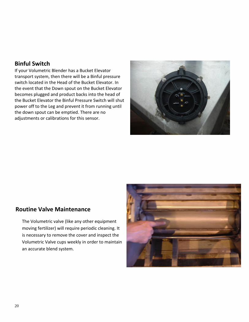
Binful Switch If your Volumetric Blender has a Bucket Elevator transport system, then there will be a Binful pressure switch located in the Head of the Bucket Elevator. In the event that the Down spout on the Bucket Elevator becomes plugged and product backs into the head of the Bucket Elevator the Binful Pressure Switch will shut power off to the Leg and prevent it from running until the down spout can be emptied. There are no adjustments or calibrations for this sensor.
Routine Valve Maintenance
The Volumetric valve (like any other equipment
moving fertilizer) will require periodic cleaning. It
is necessary to remove the cover and inspect the
Volumetric Valve cups weekly in order to maintain
an accurate blend system.

21
12285 EAST MAIN STREET
MARSHALL, IL 62441
217-826-6352
WWW.YARGUS.COM
VFD SETUP
INFORMATION

22
VFD Reset Information
If a Frequency drive over loads or faults out for any reason, record the code displayed on the display of the
drive, then shut off the circuit
breaker located next to the
frequency drive. Wait until the
frequency drive powers down
completely, this can take up to
thirty seconds. Once power down is
complete the breaker can be turned
back on and the drive will reset
itself. In the normal operating mode
the drive should display “0.0” in the
display and the run light should be
on. As displayed in the picture.
Note: When foreign matter is introduced into a volumetric valve (hammer, screwdriver, or 2x4) it is normal
for the valve to overload, the above procedure should be used to reset the valve.
No regular maintenance is required for the VFD or breaker, but it should be inspected weekly to make sure
the fiberglass box is closed and latched, and that there are no air leaks allowing fertilizer to gain entry into
the panel.
VFD AMPERAGE SETTING 1) On the green terminals below the touch buttons, find a jumper wire that is tied to “SD” and going to either STF (forward) or STR (reverse). It will only be going to one of those two, as it determines motor direction. Disconnect STF or STR. 2) Press the “Mode” button once. The display should show P. (number) 3) Use the scroll wheel to go to P79. Press “set”. 4) Use the scroll wheel to go from 3 to 0. Press “set” To Change the Amperage: 1) From P79, use the scroll wheel to navigate to P9 2) Press “set” 3) Use the scroll wheel to set to desired amps 4) Press “set”

23
5) Scroll back to P79 6) Press “Set” 7) Change from 0 to 3 8) Press “Set” 9) Press mode button twice. The display should read 0.00 10) Turn off the VFD via the breaker. 11) Reconnect STF or STR 12) Turn VFD back on
VFD MANUAL RUN
1) On the green terminals below the touch buttons, find a jumper wire that is tied to “SD” and going to either STF (forward) or STR (reverse). It will only be going to one of those two, as it determines motor direction. Disconnect STF or STR. 2) Press the “Mode” button once. The display should show P. (number) 4) Use the scroll wheel to go to P79. Press “set”. 5) Use the school wheel to set the number to 0. (From 3) Press “set”. 6) Press “Mode” twice until display reads 0.00 7) Use the scroll wheel to dial in the speed of the valve (5.0 being the slowest, 55.0 being the fastest) 8) Press “set” 9) Display should flash desired speed and “F” (Forward) then return to 0.00 10) Press the “Run” key to begin turning the valve at requested speed. 11) Press “Stop” when finished. If running the wrong direction: -Press the “Mode” button once. The display should show P. (number) -Use the scroll wheel to navigate to P40. Press “Set” -Use the scroll wheel to change number to 1 (From 0) -Press “set” -Press “Mode” twice and display should read 00.0 -Press the “Run” button, valve turn should be reversed. When finished manually running: - Press the “Mode” button once. The display should show P. (number) - Using the Scroll Wheel, navigate to P79. Press “Set” -Change number from 0 to 3. Press “Set” -Press mode button twice until display reads 0.00 -Turn off the VFD -Reconnect jumper STF or STR
24
-Turn on VFD.
VFD COMPLETE RESET
1) On the green terminals below the touch buttons, find a jumper wire that is tied to “SD” and going to either STF (forward) or STR (reverse). It will only be going to one of those two, as it determines motor direction. Disconnect STF or STR. 2) Press the “Mode” button once. The display should show P. (number) 3) Turn Scroll wheel left from P0 until the display reads “ALLC” 4) Press “set” 5) Change value from 0 to 1 6) Press “set” 7) Power down VFD 8) After 10 seconds, power up VFD. 9) Check the lights above the touch buttons. There are two lights labeled PU and EXT. Press the PU/EXT button once if the light is not on PU. 10) Press the “Mode” button once. The display should show P. (number) 11) Use the scroll wheel to go to P7. Press “set”. 12) Use the scroll wheel to set the number to .8. (From 5) Press “set”. 13) Use the scroll wheel to go to P8. Press “set”. 14) Use the scroll wheel to set the number to .8. (From 5) Press “set”. 15) Use the scroll wheel to go to P22. Press “set”. 16) Use the scroll wheel to set the number to 175. Press “set”. 17) Use the scroll wheel to go to P71. Press “set”. 18) Use the scroll wheel to set the number to 13. Press “set”. 19) Use the scroll wheel to set the number to P80. Press “set”. 20) Use the scroll wheel to set the number to number 1.5 (2HP Motor) or 2.2 (3HP Motor). Press “set”. 21) Use the scroll wheel to go to P83. Press “set”. 22) Use the scroll wheel to set the number to the amount of voltage supplied (240, 380, 415, 480). Press “set”. 23) Use the scroll wheel to go to P156. Press “set”. 24) Use the scroll wheel to set the number to 16. Press “set”. 25) Use the scroll wheel to go to P157. Press “set”. 26) Use the scroll wheel to set the number to 2. Press “set”. 27) Use the scroll wheel to go to P 180. Press “set”. 28) Use the scroll wheel to set the number to 4. (From 0) Press “set”. ******Only For Systems with wires in terminals “A” and “C” on the VFD****** 29) Use the scroll wheel to go to P192 30) Use the scroll wheel to set the number to 0. (From 99). Press “set” ***************************************************************** 31) Use the scroll wheel to go to P96. Press “set”. 32) Use the scroll wheel to set the number to 1. Press “set”. 33) Press mode button twice. There should be a “1” on the screen. Press “Run”. The number should change to “2” while the drive auto tunes. When the display reads “3”, press the stop button. The drive is now tuned.

25
34) Press “Mode” button once. The display should read P96 still. 35) Use the scroll wheel to go to P79. Press “set”. 36) Use the scroll wheel to set the number to 3. Press “set”. 37) Turn VFD Power off. 38) Reconnect the wire to either STF or STR. 40) Turn VFD power on. 41) VFD setup complete.

26