VMC Controller - 世紀株式会社│SEIKI … 3.3 Valve Timer VMC Controller is equipped with a...
23
VMC Controller Operation Manual
-
Upload
vuongkhanh -
Category
Documents
-
view
227 -
download
4
Transcript of VMC Controller - 世紀株式会社│SEIKI … 3.3 Valve Timer VMC Controller is equipped with a...
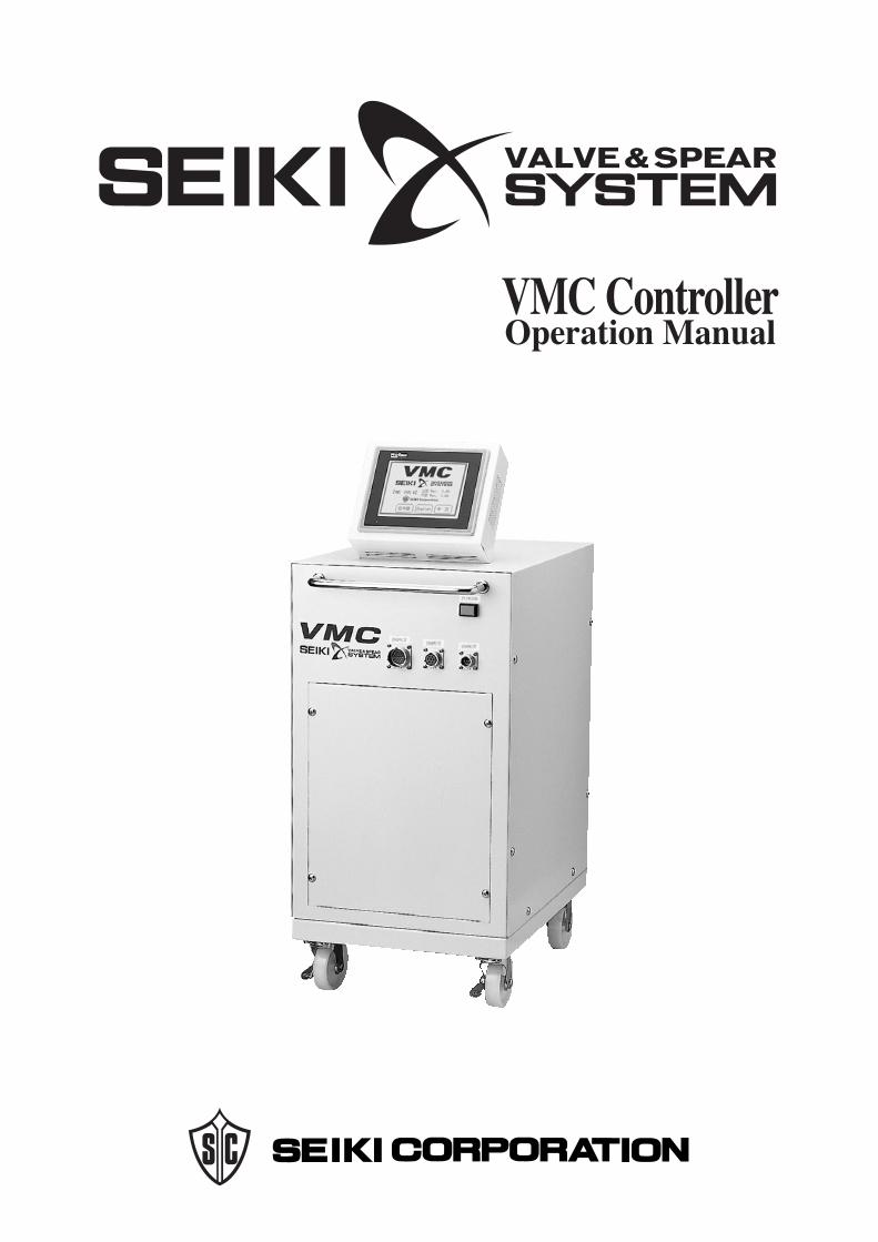
VMC ControllerOperation Manual
Important Safety Instructions
This manual contains valuable information and instructions for safe and efficient
operation of the controller. Read all instructions and safety information in this manual
carefully before operating the Controller
This manual should be retained in an easily accessible place for future reference.
We have provided important safety messages and symbols in this manual. Understand
these safety instructions before continue this manual.
� � � � WARNING You could be killed or seriously injured if you don't follow
instructions.
� � � � CAUTIONYou may be injured or your property can be damaged if you
don't follow instructions.
Maintenance
� � � � � WARNING � � � � CAUTION
Turn the power off by turning the circuit
breaker off when you need to check inside of
the controller for repair or service purpose.
Failure to follow this instruction could result in
electrical shock.
The molding must be adequately grounded
when it is being heated without the molding
machine.
Inadequate grounding could result in electrical
shock.
Clean or replace the filter semi-annually.
The clogged filter may cause the higher
temperature and it may result in operation
error, fire or damaging the controller.
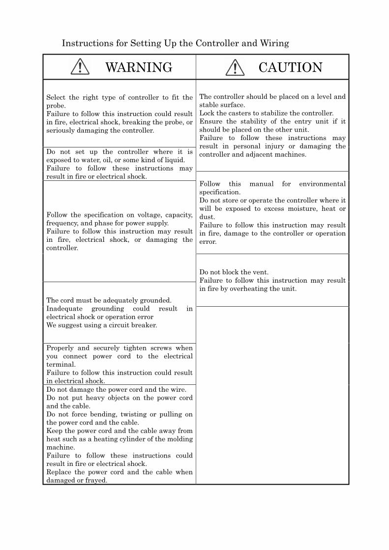
Instructions for Setting Up the Controller and Wiring
� � � � � WARNING � � � � � CAUTION
Select the right type of controller to fit the
probe.
Failure to follow this instruction could result
in fire, electrical shock, breaking the probe, or
seriously damaging the controller.
The controller should be placed on a level and
stable surface.
Lock the casters to stabilize the controller.
Ensure the stability of the entry unit if it
should be placed on the other unit.
Failure to follow these instructions may
result in personal injury or damaging the
controller and adjacent machines. Do not set up the controller where it is
exposed to water, oil, or some kind of liquid.
Failure to follow these instructions may
result in fire or electrical shock.
Follow this manual for environmental
specification.
Do not store or operate the controller where it
will be exposed to excess moisture, heat or
dust.
Failure to follow this instruction may result
in fire, damage to the controller or operation
error.
Follow the specification on voltage, capacity,
frequency, and phase for power supply.
Failure to follow this instruction may result
in fire, electrical shock, or damaging the
controller.
Do not block the vent.
Failure to follow this instruction may result
in fire by overheating the unit.
The cord must be adequately grounded.
Inadequate grounding could result in
electrical shock or operation error
We suggest using a circuit breaker.
Properly and securely tighten screws when
you connect power cord to the electrical
terminal.
Failure to follow this instruction could result
in electrical shock.
Do not damage the power cord and the wire.
Do not put heavy objects on the power cord
and the cable.
Do not force bending, twisting or pulling on
the power cord and the cable.
Keep the power cord and the cable away from
heat such as a heating cylinder of the molding
machine.
Failure to follow these instructions could
result in fire or electrical shock.
Replace the power cord and the cable when
damaged or frayed.
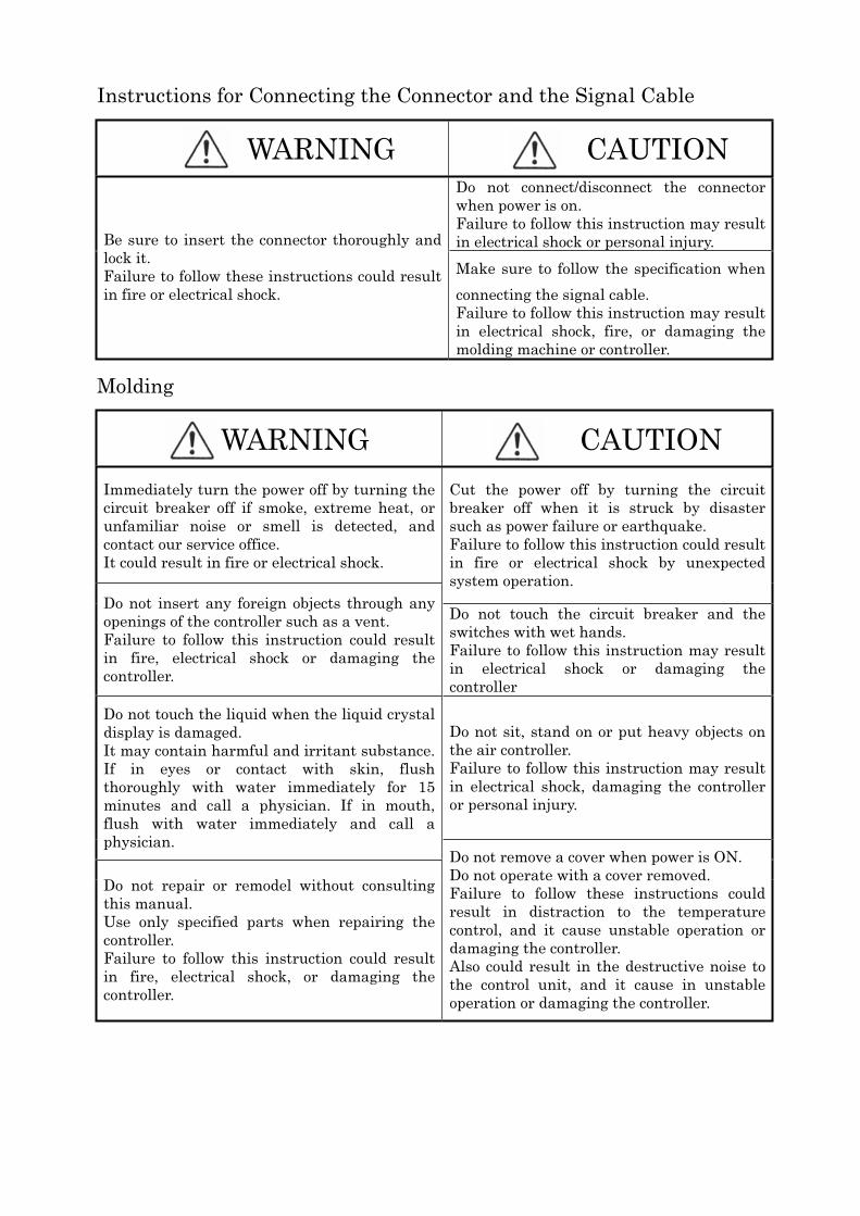
Instructions for Connecting the Connector and the Signal Cable
� � � � � WARNING � � � � � CAUTION
Do not connect/disconnect the connector
when power is on.
Failure to follow this instruction may result
in electrical shock or personal injury. Be sure to insert the connector thoroughly and
lock it.
Failure to follow these instructions could result
in fire or electrical shock.
Make sure to follow the specification when
connecting the signal cable.
Failure to follow this instruction may result
in electrical shock, fire, or damaging the
molding machine or controller.
Molding
� � � � WARNING � � � � � CAUTION
Immediately turn the power off by turning the
circuit breaker off if smoke, extreme heat, or
unfamiliar noise or smell is detected, and
contact our service office.
It could result in fire or electrical shock.
Cut the power off by turning the circuit
breaker off when it is struck by disaster
such as power failure or earthquake.
Failure to follow this instruction could result
in fire or electrical shock by unexpected
system operation.
Do not insert any foreign objects through any
openings of the controller such as a vent.
Failure to follow this instruction could result
in fire, electrical shock or damaging the
controller.
Do not touch the circuit breaker and the
switches with wet hands.
Failure to follow this instruction may result
in electrical shock or damaging the
controller
Do not sit, stand on or put heavy objects on
the air controller.
Failure to follow this instruction may result
in electrical shock, damaging the controller
or personal injury.
Do not touch the liquid when the liquid crystal
display is damaged.
It may contain harmful and irritant substance.
If in eyes or contact with skin, flush
thoroughly with water immediately for 15
minutes and call a physician. If in mouth,
flush with water immediately and call a
physician.
Do not repair or remodel without consulting
this manual.
Use only specified parts when repairing the
controller.
Failure to follow this instruction could result
in fire, electrical shock, or damaging the
controller.
Do not remove a cover when power is ON.
Do not operate with a cover removed.
Failure to follow these instructions could
result in distraction to the temperature
control, and it cause unstable operation or
damaging the controller.
Also could result in the destructive noise to
the control unit, and it cause in unstable
operation or damaging the controller.
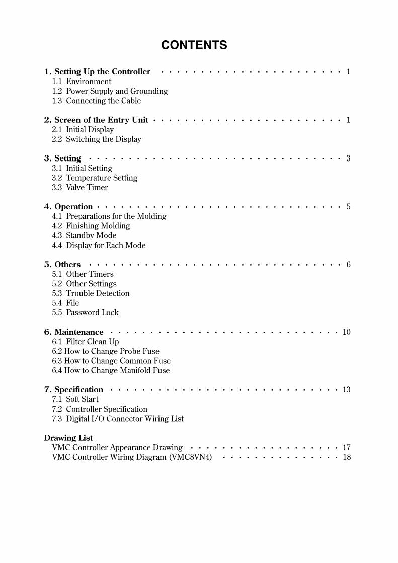
CONTENTS
・・・・・・・・・・・・・・・・・・・・・・・
・・・・・・・・・・・・・・・・・・・・・・・・
・・・・・・・・・・・・・・・・・・・・・・・・・・・・・・・・
・・・・・・・・・・・・・・・・・・・・・・・・・・・・・・・
・・・・・・・・・・・・・・・・・・・・・・・・・・・・・・・・
・・・・・・・・・・・・・・・・・・・・・・・・・・・・・
・・・・・・・・・・・・・・・・・・・・・・・・・・・・・
・・・・・・・・・・・・・・・・・・・ ・・・・・・・・・・・・・・・
1
�
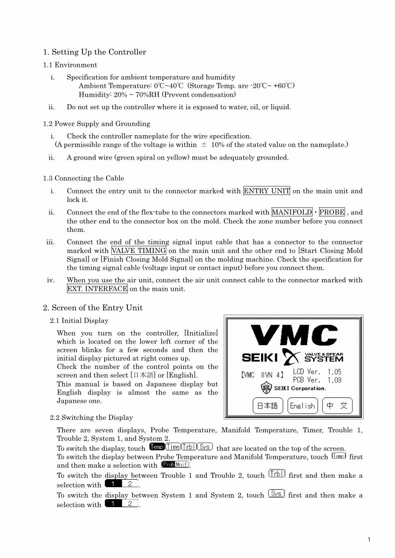
1. Setting Up the Controller
1.1 Environment
i. Specification for ambient temperature and humidity
Ambient Temperature: 0�~40� (Storage Temp. are -20�~ +60�)
Humidity: 20% ~ 70%RH (Prevent condensation)
ii. Do not set up the controller where it is exposed to water, oil, or liquid.
1.2 Power Supply and Grounding
i. Check the controller nameplate for the wire specification.
(A permissible range of the voltage is within � 10% of the stated value on the nameplate.)
ii. A ground wire (green spiral on yellow) must be adequately grounded.
1.3 Connecting the Cable
i. Connect the entry unit to the connector marked with ENTRY UNIT on the main unit and
lock it.
ii. Connect the end of the flex-tube to the connectors marked with MANIFOLD�PROBE , and
the other end to the connector box on the mold. Check the zone number before you connect
them.
iii. Connect the end of the timing signal input cable that has a connector to the connector
marked with VALVE TIMING on the main unit and the other end to [Start Closing Mold
Signal] or [Finish Closing Mold Signal] on the molding machine. Check the specification for
the timing signal cable (voltage input or contact input) before you connect them.
iv. When you use the air unit, connect the air unit connect cable to the connector marked with
EXT. INTERFACE on the main unit.
2. Screen of the Entry Unit
2.1 Initial Display
When you turn on the controller, [Initialize]
which is located on the lower left corner of the
screen blinks for a few seconds and then the
initial display pictured at right comes up.
Check the number of the control points on the
screen and then select [���] or [English].
This manual is based on Japanese display but
English display is almost the same as the
Japanese one.
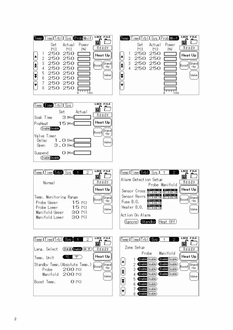
2.2 Switching the Display
There are seven displays, Probe Temperature, Manifold Temperature, Timer, Trouble 1,
Trouble 2, System 1, and System 2.
To switch the display, touch that are located on the top of the screen.
To switch the display between Probe Temperature and Manifold Temperature, touch first
and then make a selection with .
To switch the display between Trouble 1 and Trouble 2, touch first and then make a
selection with .
To switch the display between System 1 and System 2, touch first and then make a
selection with .
2
33
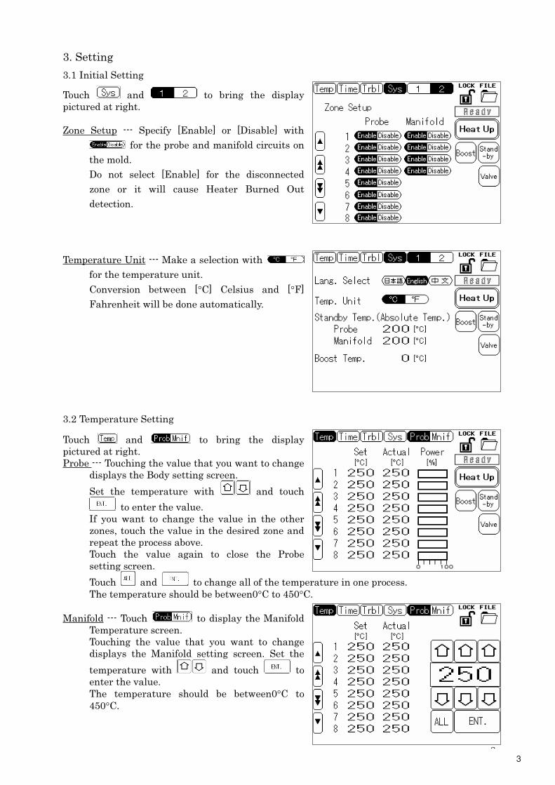
3. Setting
3.1 Initial Setting
Touch and to bring the display
pictured at right.
Zone Setup --- Specify [Enable] or [Disable] with
for the probe and manifold circuits on
the mold.
Do not select [Enable] for the disconnected
zone or it will cause Heater Burned Out
detection.
Temperature Unit --- Make a selection with
for the temperature unit.
Conversion between [°C] Celsius and [°F]
Fahrenheit will be done automatically.
3.2 Temperature Setting
Touch and to bring the display
pictured at right.
Probe --- Touching the value that you want to change
displays the Body setting screen.
Set the temperature with and touch
to enter the value.
If you want to change the value in the other
zones, touch the value in the desired zone and
repeat the process above.
Touch the value again to close the Probe
setting screen.
Touch and to change all of the temperature in one process.
The temperature should be between0°C to 450°C.
Manifold --- Touch to display the Manifold
Temperature screen.
Touching the value that you want to change
displays the Manifold setting screen. Set the
temperature with and touch to
enter the value.
The temperature should be between0°C to
450°C.
4
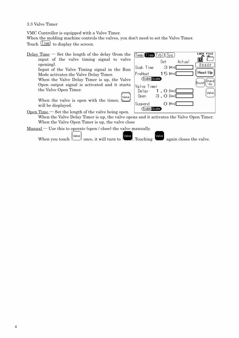
3.3 Valve Timer
VMC Controller is equipped with a Valve Timer.
When the molding machine controls the valves, you don't need to set the Valve Timer.
Touch to display the screen.
Delay Time --- Set the length of the delay (from the
input of the valve timing signal to valve
opening).
Input of the Valve Timing signal in the Run
Mode activates the Valve Delay Timer.
When the Valve Delay Timer is up, the Valve
Open output signal is activated and it starts
the Valve Open Timer.
When the valve is open with the timer,
will be displayed.
Open Time --- Set the length of the valve being open.
When the Valve Delay Timer is up, the valve opens and it activates the Valve Open Timer.
When the Valve Open Timer is up, the valve close.
Manual --- Use this to operate (open / close) the valve manually.
When you touch once, it will turn to . Touching again closes the valve.
5
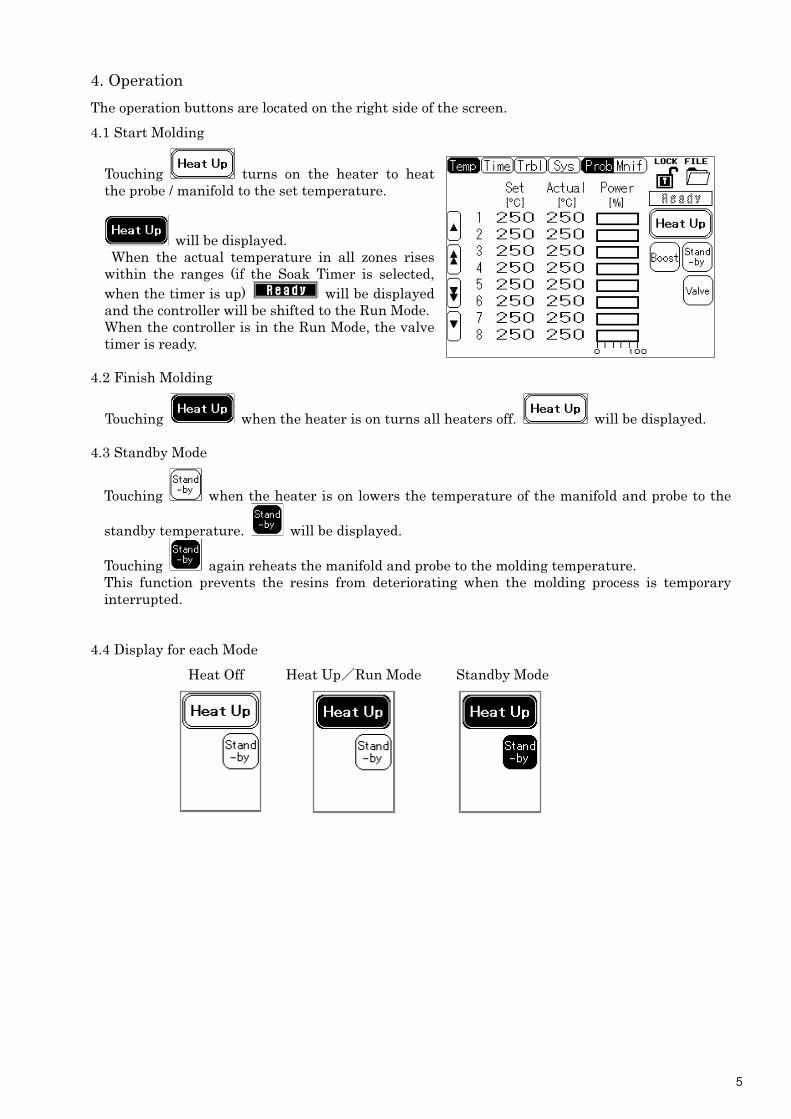
4. Operation
The operation buttons are located on the right side of the screen.
4.1 Start Molding
Touching turns on the heater to heat
the probe / manifold to the set temperature.
will be displayed.
When the actual temperature in all zones rises
within the ranges (if the Soak Timer is selected,
when the timer is up) will be displayed
and the controller will be shifted to the Run Mode.
When the controller is in the Run Mode, the valve
timer is ready.
4.2 Finish Molding
Touching when the heater is on turns all heaters off. will be displayed.
4.3 Standby Mode
Touching when the heater is on lowers the temperature of the manifold and probe to the
standby temperature. will be displayed.
Touching again reheats the manifold and probe to the molding temperature.
This function prevents the resins from deteriorating when the molding process is temporary
interrupted.
4.4 Display for each Mode�
Heat Off Heat Up�Run Mode Standby Mode
6
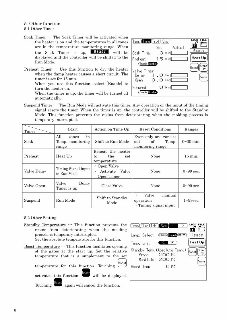
5. Other function
5.1 Other Timer
Soak Timer --- The Soak Timer will be activated when
the heater is on and the temperatures in all zones
are in the temperature monitoring range. When
the Soak Timer is up, will be
displayed and the controller will be shifted to the
Run Mode.
Preheat Timer --- Use this function to dry the heater
when the damp heater causes a short circuit. The
timer is set for 15 min.
When you use this function, select [Enable] to
turn the heater on.
When the timer is up, the timer will be turned off
automatically.
Suspend Timer --- The Run Mode will activate this timer. Any operation or the input of the timing
signal resets the timer. When the timer is up, the controller will be shifted to the Standby
Mode. This function prevents the resins from deteriorating when the molding process is
temporary interrupted.
Timer Start Action on Time Up Reset Conditions Ranges
Soak
All zones in
Temp. monitoring
range
Shift to Run Mode
Even only one zone is
out of Temp.
monitoring range.
0~30 min.
Preheat Heat Up
Reheat the heater
to the set
temperature
None 15 min.
Valve Delay Timing Signal input
in Run Mode
�Open Valve
� Activate Valve
Open Timer
None 0~99 sec.
Valve Open Valve Delay
Timer is up Close Valve None 0~99 sec.
Suspend Run Mode Shift to Standby
Mode
� Valve manual
operation
�Timing signal input
1~99sec.
5.2 Other Setting
Standby Temperature --- This function prevents the
resins from deteriorating when the molding
process is temporary interrupted.
Set the absolute temperature for this function.
Boost Temperature --- This function facilitates opening
of the gates at the start up. Set the relative
temperature that is a supplement to the set
temperature for this function. Touching
activates this function. will be displayed.
Touching again will cancel the function.
7
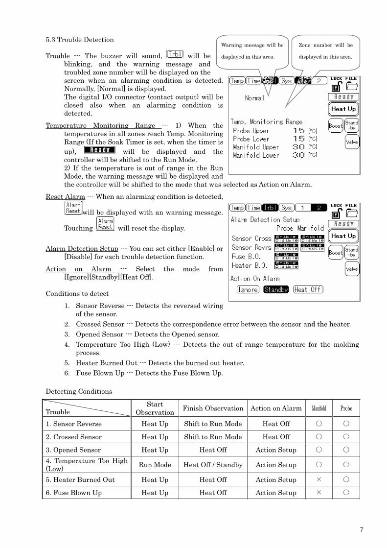
5.3 Trouble Detection
Trouble --- The buzzer will sound, will be
blinking, and the warning message and
troubled zone number will be displayed on the
screen when an alarming condition is detected.
Normally, [Normal] is displayed.
The digital I/O connector (contact output) will be
closed also when an alarming condition is
detected.
Temperature Monitoring Range --- 1) When the
temperatures in all zones reach Temp. Monitoring
Range (If the Soak Timer is set, when the timer is
up), will be displayed and the
controller will be shifted to the Run Mode.
2) If the temperature is out of range in the Run
Mode, the warning message will be displayed and
the controller will be shifted to the mode that was selected as Action on Alarm.
Reset Alarm --- When an alarming condition is detected,
will be displayed with an warning message.
Touching will reset the display.
Alarm Detection Setup --- You can set either [Enable] or
[Disable] for each trouble detection function.
Action on Alarm --- Select the mode from
[Ignore][Standby][Heat Off].
Conditions to detect
1. Sensor Reverse --- Detects the reversed wiring
of the sensor.
2. Crossed Sensor --- Detects the correspondence error between the sensor and the heater.
3. Opened Sensor --- Detects the Opened sensor.
4. Temperature Too High (Low) --- Detects the out of range temperature for the molding
process.
5. Heater Burned Out --- Detects the burned out heater.
6. Fuse Blown Up --- Detects the Fuse Blown Up.
Detecting Conditions
Trouble
Start
ObservationFinish Observation Action on Alarm Manifold Probe
1. Sensor Reverse Heat Up Shift to Run Mode Heat Off
2. Crossed Sensor Heat Up Shift to Run Mode Heat Off
3. Opened Sensor Heat Up Heat Off Action Setup
4. Temperature Too High
(Low)Run Mode Heat Off / Standby Action Setup
5. Heater Burned Out Heat Up Heat Off Action Setup
6. Fuse Blown Up Heat Up Heat Off Action Setup
Zone number will be
displayed in this area.
Warning message will be
displayed in this area.
8
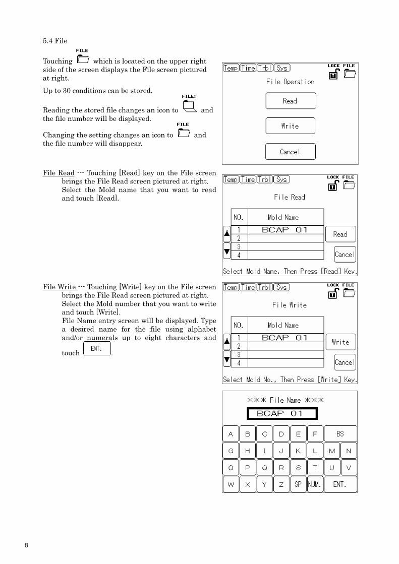
5.4 File
Touching which is located on the upper right
side of the screen displays the File screen pictured
at right.
Up to 30 conditions can be stored.
Reading the stored file changes an icon to and
the file number will be displayed.
Changing the setting changes an icon to and
the file number will disappear.
File Read --- Touching [Read] key on the File screen
brings the File Read screen pictured at right.
Select the Mold name that you want to read
and touch [Read].
File Write --- Touching [Write] key on the File screen
brings the File Read screen pictured at right.
Select the Mold number that you want to write
and touch [Write].
File Name entry screen will be displayed. Type
a desired name for the file using alphabet
and/or numerals up to eight characters and
touch .
9
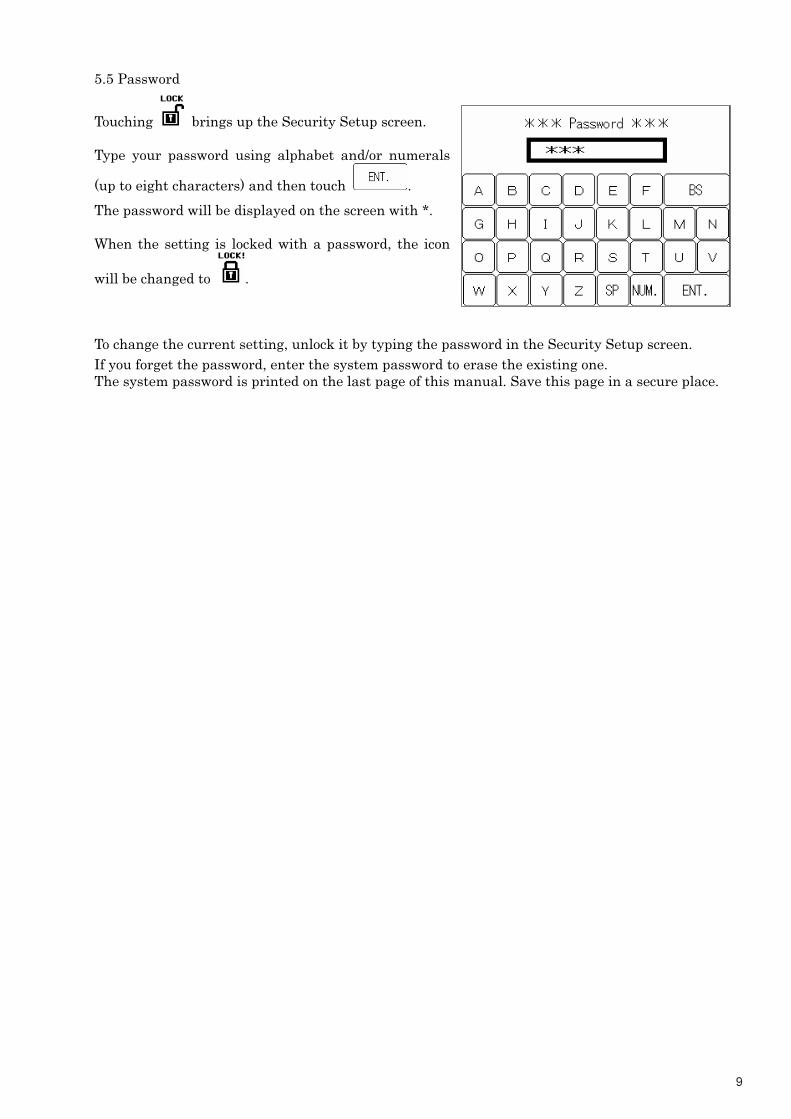
5.5 Password
Touching brings up the Security Setup screen.
Type your password using alphabet and/or numerals
(up to eight characters) and then touch .
The password will be displayed on the screen with *.
When the setting is locked with a password, the icon
will be changed to .
To change the current setting, unlock it by typing the password in the Security Setup screen.
If you forget the password, enter the system password to erase the existing one.
The system password is printed on the last page of this manual. Save this page in a secure place.
10
6. Maintenance
6.1 Filter Clean up
The filter needs to be cleaned annually. A dirty filter causes damage to the controller.
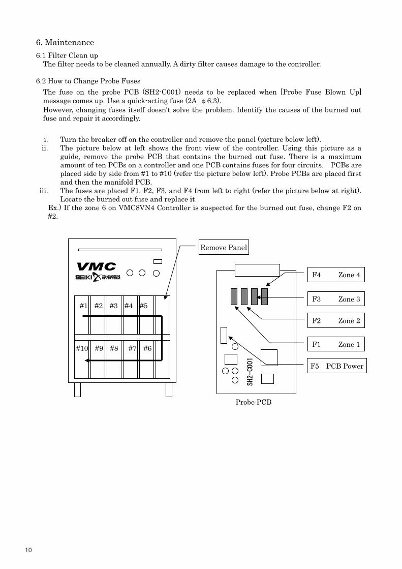
6.2 How to Change Probe Fuses
The fuse on the probe PCB (SH2-C001) needs to be replaced when [Probe Fuse Blown Up]
message comes up. Use a quick-acting fuse (2A �6.3).
However, changing fuses itself doesn't solve the problem. Identify the causes of the burned out
fuse and repair it accordingly.
i. Turn the breaker off on the controller and remove the panel (picture below left).
ii. The picture below at left shows the front view of the controller. Using this picture as a
guide, remove the probe PCB that contains the burned out fuse. There is a maximum
amount of ten PCBs on a controller and one PCB contains fuses for four circuits. PCBs are
placed side by side from #1 to #10 (refer the picture below left). Probe PCBs are placed first
and then the manifold PCB.
iii. The fuses are placed F1, F2, F3, and F4 from left to right (refer the picture below at right).
Locate the burned out fuse and replace it.
Ex.) If the zone 6 on VMC8VN4 Controller is suspected for the burned out fuse, change F2 on
#2.
�
�
�
�
�
�
�
�
�
�
�
�
�
�
�
�
�
#1 #2 #3 #4 #5
#10 #9 #8 #7 #6 F1 Zone 1
F2 Zone 2
F3 Zone 3
F4 Zone 4
��������
F5 PCB Power
Remove Panel
Probe PCB
VMC
11
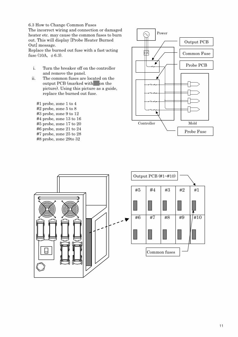
Output PCB (#1~#10)
Common fuses
6.3 How to Change Common Fuses
The incorrect wiring and connection or damaged
heater etc. may cause the common fuses to burn
out. This will display [Probe Heater Burned
Out] message.
Replace the burned out fuse with a fast-acting
fuse (10A, �6.3).
i. Turn the breaker off on the controller
and remove the panel.
ii. The common fuses are located on the
output PCB (marked with� on the
picture). Using this picture as a guide,
replace the burned out fuse.
#1 probe, zone 1 to 4
#2 probe, zone 5 to 8
#3 probe, zone 9 to 12
#4 probe, zone 13 to 16
#5 probe, zone 17 to 20
#6 probe, zone 21 to 24
#7 probe, zone 25 to 28
#8 probe, zone 29to 32
#5 #4 #3 #2 #1
#6 #7 #8 #9 #10
Controller Mold
Power
Probe Fuse
Probe PCB
Output PCB
Common Fuse
12
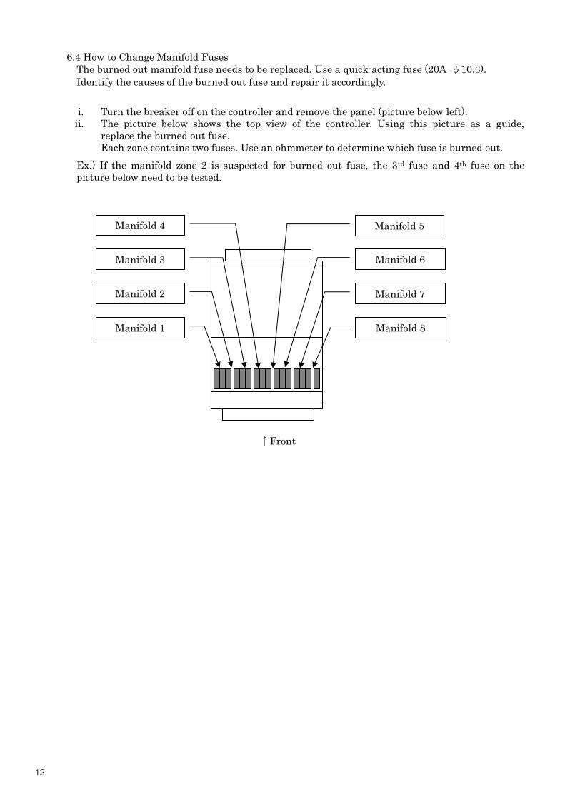
6.4 How to Change Manifold Fuses
The burned out manifold fuse needs to be replaced. Use a quick-acting fuse (20A �10.3).
Identify the causes of the burned out fuse and repair it accordingly.
i. Turn the breaker off on the controller and remove the panel (picture below left).
ii. The picture below shows the top view of the controller. Using this picture as a guide,
replace the burned out fuse.
Each zone contains two fuses. Use an ohmmeter to determine which fuse is burned out.
Ex.) If the manifold zone 2 is suspected for burned out fuse, the 3rd fuse and 4th fuse on the
picture below need to be tested.
Front
Manifold 1
Manifold 2
Manifold 3
Manifold 4 Manifold 5
Manifold 6
Manifold 7
Manifold 8
13
7.Specification
7.1 Soft Start
Heat up the probe and the manifold with a stable temperature�30°C /�min.�to avoid stress on
the heater. (Output for the probe: start from 10%, manifold: start from 50%)
With this function the heater lasts longer.
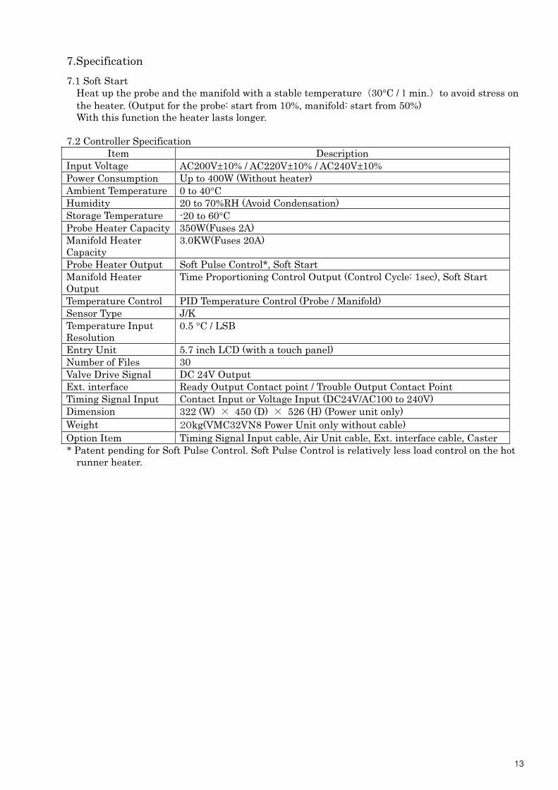
7.2 Controller Specification
Item Description
Input Voltage AC200V±10% / AC220V±10% / AC240V±10%
Power Consumption Up to 400W (Without heater)
Ambient Temperature 0 to 40°C
Humidity 20 to 70%RH (Avoid Condensation)
Storage Temperature -20 to 60°C
Probe Heater Capacity 350W(Fuses 2A)
Manifold Heater
Capacity
3.0KW(Fuses 20A)
Probe Heater Output Soft Pulse Control*, Soft Start
Manifold Heater
Output
Time Proportioning Control Output (Control Cycle: 1sec), Soft Start
Temperature Control PID Temperature Control (Probe / Manifold)
Sensor Type J/K
Temperature Input
Resolution
0.5 °C / LSB
Entry Unit 5.7 inch LCD (with a touch panel)
Number of Files 30
Valve Drive Signal DC 24V Output
Ext. interface Ready Output Contact point / Trouble Output Contact Point
Timing Signal Input Contact Input or Voltage Input (DC24V/AC100 to 240V)
Dimension 322 (W) � 450 (D) � 526 (H) (Power unit only)
Weight ��kg(VMC32VN8 Power Unit only without cable)
Option Item Timing Signal Input cable, Air Unit cable, Ext. interface cable, Caster
* Patent pending for Soft Pulse Control. Soft Pulse Control is relatively less load control on the hot
runner heater.

14
7.3 Ext. Interface Connection Table
Pin # Description Pin # Description
1 Air pressure Too Low (Contact Input) 13 Trouble� � � � (Contact Output)
2 External Alarm� (Contact Input) 14 Trouble� � � � (Contact Output)
3 Reserved � � � (Contact Input) 15 Reserved� � � (Contact Output)
4 Reserved � � � (Contact Input) 16 Reserved� � � (Contact Output)
5 Contact Input Common (OV) 17 Open Valve� � (Contact Output)
6 Voltage Output Common (OV) 18 Open Valve� � (Contact Output)
7 Ready� � � (24V Voltage Output) 19 Not Connected
8 Trouble� � (24V Voltage Output) 20 Not Connected
9 Reserved� (24V Voltage Output) 21 Not Connected
10 Open Valve (24V Voltage Output) 22 Not Connected
11 Ready� � � (Contact Output) 23 Not Connected
12 Ready� � � (Contact Output) 24 Not Connected
15
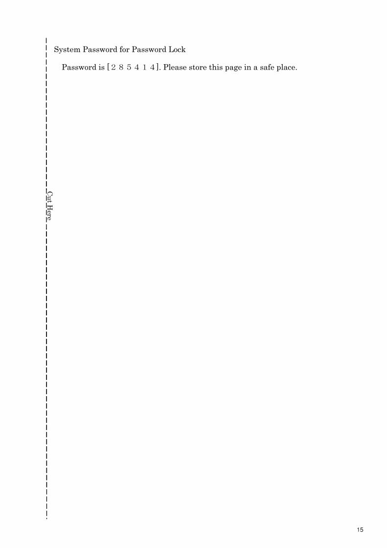
System Password for Password Lock
Password is [������]. Please store this page in a safe place.
Cu
t H
ere
17
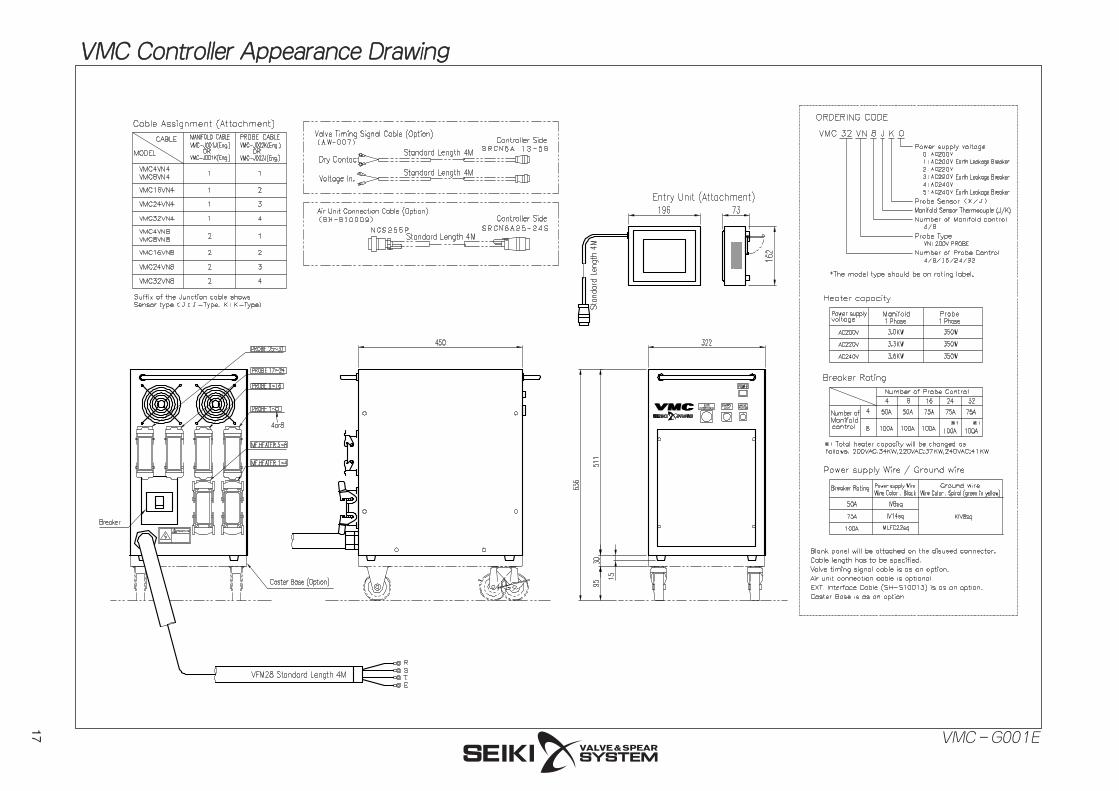
VMC Controller Appearance DrawingVMC Controller Appearance Drawing
VMC-G001E
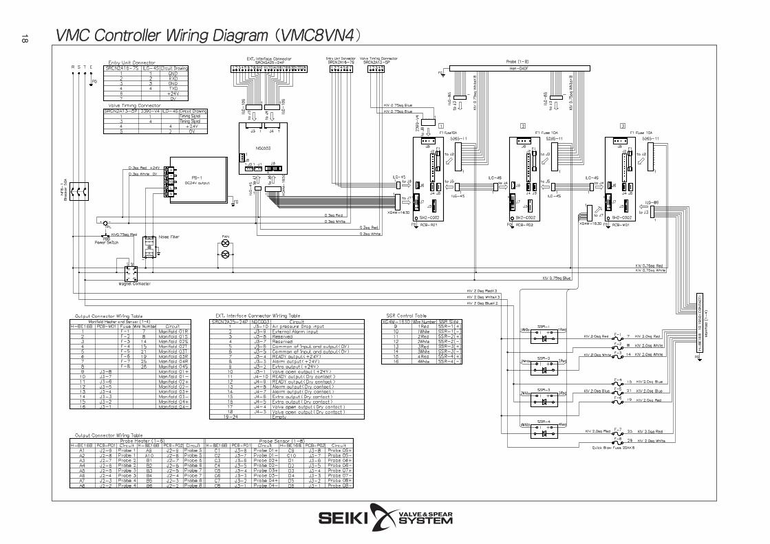
18 VMC Controller Wiring DiagramVMC Controller Wiring Diagram ( (VMC8VN4VMC8VN4)
2006.6.100
Seiki Network4364 Katako,Bansei-Cho,Yonezawa-City,Yamagata 992-1125TEL: 81-(0)238-28-5411 FAX: 81-(0)238-28-1363URL http://www.seiki-hot.com/E-mail [email protected]
Tokyo Office4F.Kawamura Bldg., 5-10-6 Shinbashi,Minato-ku,Tokyo 105-0004TEL: 81-(0)3-5777-0601 FAX: 81-(0)3-5777-0651
Osaka Office6F. Shin-osakamaru Bldg., 1-18-5 Higashinakajima,Higashiyodogawa-Ku,Osaka-City,Osaka 533-0033TEL: 81-(0)6-6323-6072 FAX: 81-(0)6-6325-4056
Nagoya Office6F.Office-Kurond Bldg., 3-108 Issha,Meitou-Ku,Nagoya-City, Aichi 465-0093TEL: 81-(0)52-704-5692 FAX: 81-(0)52-704-5708
Touhoku Office / Overseas Group4364 Katako, Bansei-Cho,Yonezawa-City,Yamagata 992-1125TEL: 81-(0)238-28-1250 FAX: 81-(0)238-28-1222
C/O MITSUI PLASTICS TRADING CO.,LTD.Room 3802, United Plaza,No.1468 Nanjing Road (West), Shanghai, China 200040TEL: 86-(0)21-6279-3355 FAX: 86-(0)21-6289-5115
Guanlan Techno Centre,B District 5F, Miaoxi Industrial Zone, Guihua Baoan, Shenzhen, China 518110TEL: 86-(0)755-2798-8107 FAX: 86-(0)755-2798-8124
C/O KISHIMOTO SANGYO (THAILAND) LTD.159 Sermmit Tower, 11th Floor, Sukhumvit 21 Road(Asoke),North Klongtoey,Watana.Bangkok 10110,ThailandTEL: 66-(0)2-260-8367 FAX: 66-(0)2-260-8368
Mitsui Plastics Inc100 High Grove Blvd. Glendale heights, IL 60139TEL: 1-630-924-8800 FAX: 1-630-924-8879
Song Won Industrial Co., Ltd.2F,22-3,Maesanro-1ga, Kwunsun-ku, Suwon-Si,Kyung-Ki-Do,KoreaTEL: 82-(0)31-253-8030 FAX: 82-(0)31-253-8031
Head Office
Business Office(Japan)
Shanghai Office(China)
Shenzhen Office(China)
Bangkok Office(Thailand)
U.S.A.
Korea
Taiwan
U.K.
Germany
Austraria
Hong Kong
Thailand
Singapore
Malaysia
Supiya Enterprise Co.,Ltd.2F. No.380 Sec.1, Fu Hsing S.Rd.,Taipei, TaiwanTEL: 886-(0)2-2701-1158 FAX: 886-(0)2-2754-9118
Eastern Plastics Machinery Ltd.Eastern House, Coggeshall Ind. Park,Coggeshall, Essex, CO61TW, EnglandTEL: 44-(0)1376-562288 FAX: 44-(0)1376-561385
Franz Sax KonstruktionsbueroFruehlingstrasse19,90431 Nuernberg, GermanyTEL: 49-(0)911-302184 FAX: 49-(0)911-301480
J.H.MACHINERY PTY LTD.2-48 Reserve Road, Beaumaris,Victoria, 3193, AustraliaTEL: 61-(0)3-9589-0187 FAX: 61-(0)3-9589-6450
AK&M Trading Co.,LTD.Unit 1702-4, Lippo Centre Tower 2, 89 Queensway, Hong Kong, ChinaTEL: 852-2511-0123 FAX: 852-2802-2822
KISHIMOTO SANGYO (HONGKONG) CO.,LTD.Unit 2608, The Metropolis Tower, 10 Metropolis Drive Hunghom, Kowloon, Hong Kong, ChinaTEL: 852-2311-8377 FAX: 852-2366-0651
KISHIMOTO SANGYO (THAILAND) LTD.159 Sermmit Tower, 11th. Floor, Sukhumvit 21 Rd. (Asoke),North Klongtoey, Watana, Bangkok 10110, ThailandTEL: 66-(0)2-260-8624 FAX: 66-(0)2-260-8631
KISHIMOTO SANGYO (ASIA) PTE.,LTD.101 Thomson Road, #30-02/04 United Square,Singapore 307591TEL: 65-6255-3188 FAX: 65-6255-3867
KISHIMOTO SANGYO (MALAYSIA) SDN.,BHD.6th. Floor, Wisma Genting Jalan SultanIsmail, 50250, Kuala Lumpur, MalaysiaTEL: 60-(0)3-2162-4011 FAX: 60-(0)3-2162-4078
AGENTS
AGENTS