VLT® AutomationDrive FC 302 90-1200 kWfiles.danfoss.com/download/Drives/MG33U402.pdf · Chapter 1...
122
MAKING MODERN LIVING POSSIBLE Operating Instructions VLT ® AutomationDrive FC 302 90–1200 kW www.danfoss.com/drives
Transcript of VLT® AutomationDrive FC 302 90-1200 kWfiles.danfoss.com/download/Drives/MG33U402.pdf · Chapter 1...

MAKING MODERN LIVING POSSIBLE
Operating InstructionsVLT® AutomationDrive FC 30290–1200 kW
www.danfoss.com/drives


Contents
1 Introduction 4
1.1 How to Read these Operating Instructions 4
1.1.1 Approvals 4
2 Safety Instructions and General Warning 6
2.1 Safety Regulations 6
2.1.1 Disposal Instruction 6
2.1.2 Caution 6
2.1.3 Software Version 6
2.1.4 High Voltage 6
2.1.5 Safety Instructions 6
2.1.6 General Warning 7
2.1.7 Before Commencing Repair Work 7
2.1.8 Avoid Unintended Start 7
2.1.9 Safe Torque Off (STO) 7
2.1.10 IT Mains 7
3 How to Install 8
3.1 Pre-installation 8
3.1.1 Planning the Installation Site 8
3.1.2 Receiving the Frequency Converter 8
3.1.3 Transportation and Unpacking 8
3.1.4 Lifting 8
3.1.5 Mechanical Dimensions 11
3.1.6 Rated Power 18
3.2 Mechanical Installation 19
3.2.1 Tools Needed 19
3.2.2 General Considerations 19
3.2.3 Terminal Locations - Enclosure Type D 20
3.2.4 Terminal Locations - E Enclosures 23
3.2.5 Terminal Locations - Frame size F 28
3.2.6 Cooling and Airflow 32
3.2.7 Installation on the Wall - IP21 (NEMA 1) and IP54 (NEMA 12) Units 34
3.2.8 Gland/Conduit Entry - IP21 (NEMA 1) and IP54 (NEMA12) 34
3.2.9 IP21 Drip Shield Installation (Enclosure Types D1 and D2) 36
3.3 Field Installation of Options 36
3.3.1 Installation of Duct Cooling Kit in Rittal Enclosures 36
3.3.2 Installation of Top-only Duct Cooling Kit 37
3.3.3 Installation of Top and Bottom Covers for Rittal Enclosures 37
3.3.4 Installation of Top and Bottom Covers 38
Contents VLT® Automation Drive FC 300 Operating Instructions
MG33U402 - Rev. 2013-12-16 1

3.3.5 Outside Installation/NEMA 3R Kit for Rittal Enclosures 38
3.3.6 Outside Installation/NEMA 3R Kit of Industrial Enclosures 39
3.3.7 Installation of IP00 to IP20 Kits 39
3.3.8 Installation of IP00s D3, D4, & E2 Cable Clamp Bracket 39
3.3.9 Installation on Pedestal 39
3.3.10 Installation of Mains Shield for Frequency Converters 40
3.3.11 Installation of Input Plate Options 40
3.3.12 Installation of D or E Loadshare Option 41
3.4 F Enclosure Panel Options 41
3.4.1 Enclsoure Type F Options 41
3.5 Electrical Installation 43
3.5.1 Power Connections 43
3.5.2 Grounding 54
3.5.3 Extra Protection (RCD) 54
3.5.4 RFI Switch 54
3.5.5 Torque 54
3.5.6 Shielded Cables 55
3.5.7 Motor Cable 55
3.5.8 Brake Cable for Frequency Converters with Factory Installed Brake Chopper Op-tion 56
3.5.9 Load Sharing 56
3.5.10 Shielding against Electrical Noise 56
3.5.11 Mains Connection 56
3.5.12 External Fan Supply 57
3.5.13 Fuses 57
3.5.14 Mains Disconnectors - Frame Size D, E and F 69
3.5.15 F-Frame Circuit Breakers 69
3.5.16 F-Frame Mains Contactors 69
3.5.17 Motor Insulation 70
3.5.18 Motor Bearing Currents 70
3.5.19 Brake Resistor Temperature Switch 70
3.5.20 Control Cable Routing 70
3.5.21 Access to Control Terminals 72
3.5.22 Electrical Installation, Control Terminals 72
3.5.23 Electrical Installation, Control Cables 73
3.5.24 Switches S201, S202, and S801 75
3.6 Connection Examples 76
3.6.1 Start/Stop 76
3.6.2 Pulse Start/Stop 76
3.7 Final Set-Up and Test 77
Contents VLT® Automation Drive FC 300 Operating Instructions
2 MG33U402 - Rev. 2013-12-16

3.8 Additional Connections 78
3.8.1 Mechanical Brake Control 78
3.8.2 Parallel Connection of Motors 78
3.8.3 Motor Thermal Protection 79
4 How to Programme 80
4.1 The Graphical and Numerical LCP 80
4.1.1 How to Programme on the Numerical Local Control Panel 81
4.1.2 Initial Commissioning 82
4.2 Quick Setup 83
4.3 Parameter Menu Structure 85
5 General Specifications 90
6 Warnings and Alarms 105
6.1 Status Messages 105
6.1.1 Warnings/Alarm Messages 105
Index 117
Contents VLT® Automation Drive FC 300 Operating Instructions
MG33U402 - Rev. 2013-12-16 3

1 Introduction
1.1 How to Read these OperatingInstructions
The frequency converter is designed to provide high shaftperformance on electrical motors. Read this manualcarefully for proper use. Incorrect handling of thefrequency converter may cause improper operation of thefrequency converter or related equipment, shorten lifetimeor cause other troubles.
These Operating Instructions help starting, installing,programming, and troubleshooting the frequencyconverter.
Chapter 1 Introduction introduces the manual and informsyou about the approvals, symbols, and abbreviations usedin this literature.
Chapter 2 Safety Instructions and General Warning entailsinstructions on how to handle the frequency convertercorrectly.
Chapter 3 How to Install guides through mechanical andtechnical installation.
Chapter 4 How to Programme shows how to operate andprogramme the frequency converter via the LCP.
Chapter 5 General Specifications contains technical dataabout the frequency converter.
Chapter 6 Warnings and Alarms assists in solving problemsthat may occur when using the frequency converter.
Available literature• The VLT AutomationDrive 90-1200 kW Operating
Instructions provide the necessary information forgetting the frequency converter up and running.
• The VLT AutomationDrive FC 301/302 Design Guideentails all technical information about thefrequency converter and customer design andapplications.
• The VLT AutomationDrive Programming Guideprovides information on how to programme andincludes complete parameter descriptions.
• The VLT AutomationDrive Profibus OperatingInstructions provide the information required forcontrolling, monitoring and programming thefrequency converter via a Profibus fieldbus.
• The VLT AutomationDrive DeviceNet OperatingInstructions provide the information required for
controlling, monitoring and programming thefrequency converter via a DeviceNet fieldbus.
Danfoss technical literature is also available online atwww.danfoss.com/drives.
1.1.1 Approvals
Table 1.1
The frequency converter complies with UL508C thermalmemory retention requirements. For more information,refer to the section Motor Thermal Protection in the DesignGuide.
NOTICEImposed limitations on the output frequency(due to export control regulations):From software version 6.72 the output frequency of thefrequency converter is limited to 590 Hz. Softwareversions 6x.xx also limit the maximum output frequencyto 590 Hz, but these versions cannot be flashed, i.e.neither downgraded nor upgraded.
The following symbols are used in this document:
WARNINGIndicates a potentially hazardous situation which couldresult in death or serious injury.
CAUTIONIndicates a potentially hazardous situation which couldresult in minor or moderate injury. It may also be usedto alert against unsafe practices.
NOTICEIndicates important information, including situations thatmay result in damage to equipment or property.
Introduction VLT® Automation Drive FC 300 Operating Instructions
4 MG33U402 - Rev. 2013-12-16
11

ConventionsNumbered lists indicate procedures.Bullet lists indicate other information and description ofillustrations.Italicised text indicates
• cross reference
• link
• footnote
• parameter name, parameter group name,parameter option
60° AVM 60° Asynchronous Vector Modulation
A Ampere/AMP
AC Alternating current
AD Air discharge
AI Analog Input
AMA Automatic Motor Adaptation
AWG American wire gauge
°C Degrees Celsius
CD Contant discharge
CM Common mode
CT Constand Torque
DC Direct current
DI Digital Input
DM Differential mode
D-TYPE Drive Dependent
EMC Electro Magnetic Compatibility
ETR Electronic Thermal Relay
fJOG Motor frequency when jog function isactivated
fM Motor frequency
fMAX The maximum output frequency the frequencyconverter applies on its output
fMIN The minimum motor frequency fromfrequency converter
fM,N Nominal motor frequency
FC Frequency converter
g Gram
Hiperface® Hiperface® is a registered trademark byStegmann
hp Horsepower
HTL HTL encoder (10-30 V) pulses - High-voltageTransistor Logic
Hz Hertz
IINV Rated Inverter Output Current
ILIM Current limit
IM,N Nominal motor current
IVLT,MAX The maximum output current
IVLT,N The rated output current supplied by thefrequency converter
kHz Kilohertz
LCP Local Control Panel
lsb Least significant bit
m Meter
mA Milliampere
MCM Mille Circular Mil
MCT Motion Control Tool
mH Millihenry Inductance
min Minute
ms Millisecond
msb Most significant bit
ηVLT Efficiency of the frequency converter definedas ratio between power output and powerinput
nF Nanofarad
NLCP Numerical Local Control Panel
Nm Newton Meters
ns Synchronous Motor Speed
On-line/Off-lineParameters
Changes to on-line parameters are activatedimmediately after the data value is changed.
Pbr,cont. Rated power of the brake resistor (averagepower during continuous braking)
PCB Printed Circuit Board
PCD Process Data
PELV Protective Extra Low Voltage
Pm Frequency converter nominal output power asHO
PM,N Nominal motor power
PM motor Permanent Magnet motor
Process PID The PID regulator maintains the desired speed,pressure, temperature, etc.
Rbr,nom The nominal resistor value that ensures abrake power on motor shaft of 150/160% for 1minute
RCD Residual Current Device
Regen Regenerative terminals
Rmin Minimum permissible brake resistor value byfrequency converter
RMS Root Mean Square
RPM Revolutions Per Minute
Rrec Resistor value and resistance of the brakeresistor
s Second
SFAVM Stator Flux oriented Asynchronous VectorModulation
STW Status Word
SMPS Switch Mode Power Supply
THD Total Harmonic Distortion
TLIM Torque limit
TTL TTL encoder (5 V) pulses - Transistor TransistorLogic
UM,N Nominal motor voltage
V Volts
VT Variable Torque
VVCplus Voltage Vector Control
Table 1.2 Abbreviations
Introduction VLT® Automation Drive FC 300 Operating Instructions
MG33U402 - Rev. 2013-12-16 5
1 1
2 Safety Instructions and General Warning
2.1 Safety Regulations
2.1.1 Disposal Instruction
Equipment containing electricalcomponents may not be disposed oftogether with domestic waste.It must be separately collected withelectrical and electronic waste accordingto local and currently valid legislation.
2.1.2 Caution
WARNINGThe frequency converter DC link capacitors remaincharged after power has been disconnected. To avoidelectrical shock hazard, disconnect the frequencyconverter from the mains before carrying outmaintenance. Before doing service on the frequencyconverter wait at least the amount of time indicatedbelow
380-500 V 90-200kW 20 minutes
250-800kW 40 minutes
525-690V 37-315kW 20 minutes
355-1200kW 30 minutes
Table 2.1 Discharge Time
2.1.3 Software Version
VLT AutomationDriveOperating InstructionsSoftware version: 7.1x
These Operating Instructions can be used for all VLTAutomationDrive frequency converters with software version7.1x.The software version number can be seen from 15-43 SoftwareVersion.
2.1.4 High Voltage
WARNINGThe voltage of the frequency converter is dangerouswhenever the frequency converter is connected tomains. Incorrect installation or operation of the motor orfrequency converter may cause damage to theequipment, serious personal injury or death. Theinstructions in this manual must consequently beobserved, as well as applicable local and national rulesand safety regulations.
WARNINGInstallation in high altitudes380-500 V: At altitudes above 3,000 m, contact Danfossregarding PELV.525-690 V: At altitudes above 2,000 m, contact Danfossregarding PELV.
2.1.5 Safety Instructions
• Make sure the frequency converter is properlyconnected to earth.
• Protect users against supply voltage.
• Protect the motor against overloading accordingto national and local regulations.
• Motor overload protection is not included in thedefault settings. To add this function, set1-90 Motor Thermal Protection to value ETR trip orETR warning. For the North American market: ETRfunctions provide class 20 motor overloadprotection, in accordance with NEC.
• The earth leakage current exceeds 3.5 mA.
• The [Off] key is not a safety switch. It does notdisconnect the frequency converter from mains.
Safety Instructions and Gen... VLT® Automation Drive FC 300 Operating Instructions
6 MG33U402 - Rev. 2013-12-16
22
2.1.6 General Warning
WARNINGTouching the electrical parts may be fatal - even afterthe equipment has been disconnected from mains.Also make sure that other voltage inputs have beendisconnected, such as load-sharing (linkage of DCintermediate circuit), as well as the motor connection forkinetic back-up.When using the frequency converter: wait at least 40minutes.Shorter time is allowed only if indicated on thenameplate for the specific unit.
CAUTIONThe earth leakage current from the frequency converterexceeds 3.5 mA. To ensure that the earth cable has agood mechanical connection to the earth connection(terminal 95), the cable cross section must be at least 10mm2 or 2 rated earth wires terminated separately. Forproper earthing for EMC, see chapter 3.5.2 Grounding.Residual Current Device This product can cause a D.C. current in the protectiveconductor. Where a residual current device (RCD) is usedfor extra protection, only an RCD of Type B (timedelayed) shall be used on the supply side of thisproduct. See also RCD Application Note MN90GX02(x=version number).Protective earthing of the frequency converter and theuse of RCDs must always follow national and localregulations.
2.1.7 Before Commencing Repair Work
1. Disconnect the frequency converter from mains.
2. Disconnect DC bus terminals 88 and 89 from loadshare applications.
3. Wait for discharge of the DC-link. See period oftime on the warning label.
4. Remove motor cable.
2.1.8 Avoid Unintended Start
While the frequency converter is connected to mains,the motor can be started/stopped using digitalcommands, bus commands, references or via the LocalControl Panel (LCP):
• Disconnect the frequency converter from mainswhenever personal safety considerations make itnecessary to avoid unintended start.
• To avoid unintended start, always activate the[Off] key before changing parameters.
• An electronic fault, temporary overload, a fault inthe mains supply, or lost motor connection maycause a stopped motor to start. The frequencyconverter with Safe Stop provides protectionagainst unintended start, if the Safe StopTerminal 37 is deactivated or disconnected.
2.1.9 Safe Torque Off (STO)
To run Safe Torque Off, additional wiring for the frequencyconverter is required, refer to Safe Torque Off OperatingInstructions for Danfoss VLT® Frequency Converters forfurther information.
2.1.10 IT Mains
Parameter 14-50 RFI Filter can be used to disconnect theinternal RFI capacitors from the RFI filter to ground in the380-500 V frequency converters. This reduces the RFIperformance to A2 level. For the 525-690 V frequencyconverters, 14-50 RFI Filter has no function. The RFI switchcannot be opened.
Safety Instructions and Gen... VLT® Automation Drive FC 300 Operating Instructions
MG33U402 - Rev. 2013-12-16 7
2 2

3 How to Install
3.1 Pre-installation
3.1.1 Planning the Installation Site
CAUTIONBefore performing the installation it is important to planthe installation of the frequency converter. Neglectingthis may result in extra work during and after instal-lation.
Select the best possible operation site by consideringthe following (see details on the following pages, andthe respective Design Guides)
• Ambient operating temperature
• Installation method
• How to cool the unit
• Position of the frequency converter
• Cable routing
• Ensure the power source supplies the correctvoltage and necessary current
• Ensure that the motor current rating is within themaximum current from the frequency converter
• If the frequency converter is without built-infuses, ensure that the external fuses are ratedcorrectly.
3.1.2 Receiving the Frequency Converter
When receiving the frequency converter, make sure thatthe packaging is intact, and be aware of any damage thatmight have occurred to the unit during transport. In casedamage has occurred, contact immediately the shippingcompany to claim the damage.
3.1.3 Transportation and Unpacking
Before unpacking the frequency converter it isrecommended that it is located as close as possible to thefinal installation site.Remove the box and handle the frequency converter onthe pallet, as long as possible.
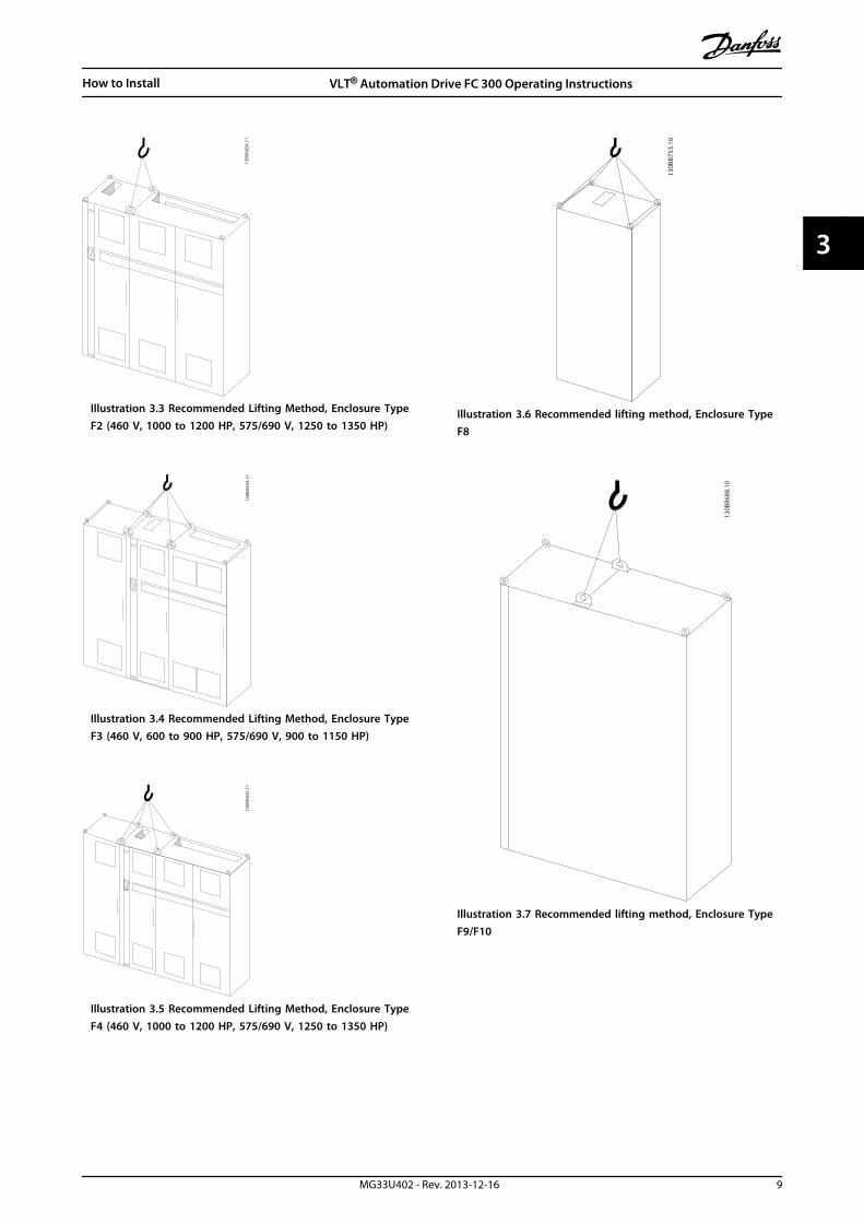
3.1.4 Lifting
Always lift the frequency converter in the dedicated liftingeyes. For all D and E2 (IP00) enclosures, use a bar to avoidbending the lifting holes of the frequency converter.
176FA24
5.10
Illustration 3.1 Recommended Lifting Method, Enclosure TypesD and E
WARNINGThe lifting bar must be able to handle the weight of thefrequency converter. See Mechanical Dimensions for theweight of the different enclosure type. Maximumdiameter for bar is 2.5 cm (1 inch). The angle from thetop of the frequency converter to the lifting cable shouldbe 60° or greater.
130B
A83
2.11
Illustration 3.2 Recommended Lifting Method, Enclsoure TypeF1 (460 V, 600 to 900 HP, 575/690 V, 900 to 1150 HP)
How to Install VLT® Automation Drive FC 300 Operating Instructions
8 MG33U402 - Rev. 2013-12-16
33
130B
A83
4.11
Illustration 3.3 Recommended Lifting Method, Enclosure TypeF2 (460 V, 1000 to 1200 HP, 575/690 V, 1250 to 1350 HP)
130B
A83
3.11
Illustration 3.4 Recommended Lifting Method, Enclosure TypeF3 (460 V, 600 to 900 HP, 575/690 V, 900 to 1150 HP)
130B
A83
5.11
Illustration 3.5 Recommended Lifting Method, Enclosure TypeF4 (460 V, 1000 to 1200 HP, 575/690 V, 1250 to 1350 HP)
130B
B753
.10
Illustration 3.6 Recommended lifting method, Enclosure TypeF8
130B
B688
.10
Illustration 3.7 Recommended lifting method, Enclosure TypeF9/F10
How to Install VLT® Automation Drive FC 300 Operating Instructions
MG33U402 - Rev. 2013-12-16 9
3 3
130B
B689
.10
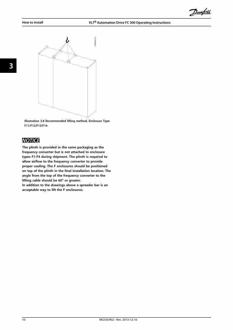
Illustration 3.8 Recommended lifting method, Enclosure TypeF11/F12/F13/F14
NOTICEThe plinth is provided in the same packaging as thefrequency converter but is not attached to enclosuretypes F1-F4 during shipment. The plinth is required toallow airflow to the frequency converter to provideproper cooling. The F enclosures should be positionedon top of the plinth in the final installation location. Theangle from the top of the frequency converter to thelifting cable should be 60° or greater.In addition to the drawings above a spreader bar is anacceptable way to lift the F enclosures.
How to Install VLT® Automation Drive FC 300 Operating Instructions
10 MG33U402 - Rev. 2013-12-16
33

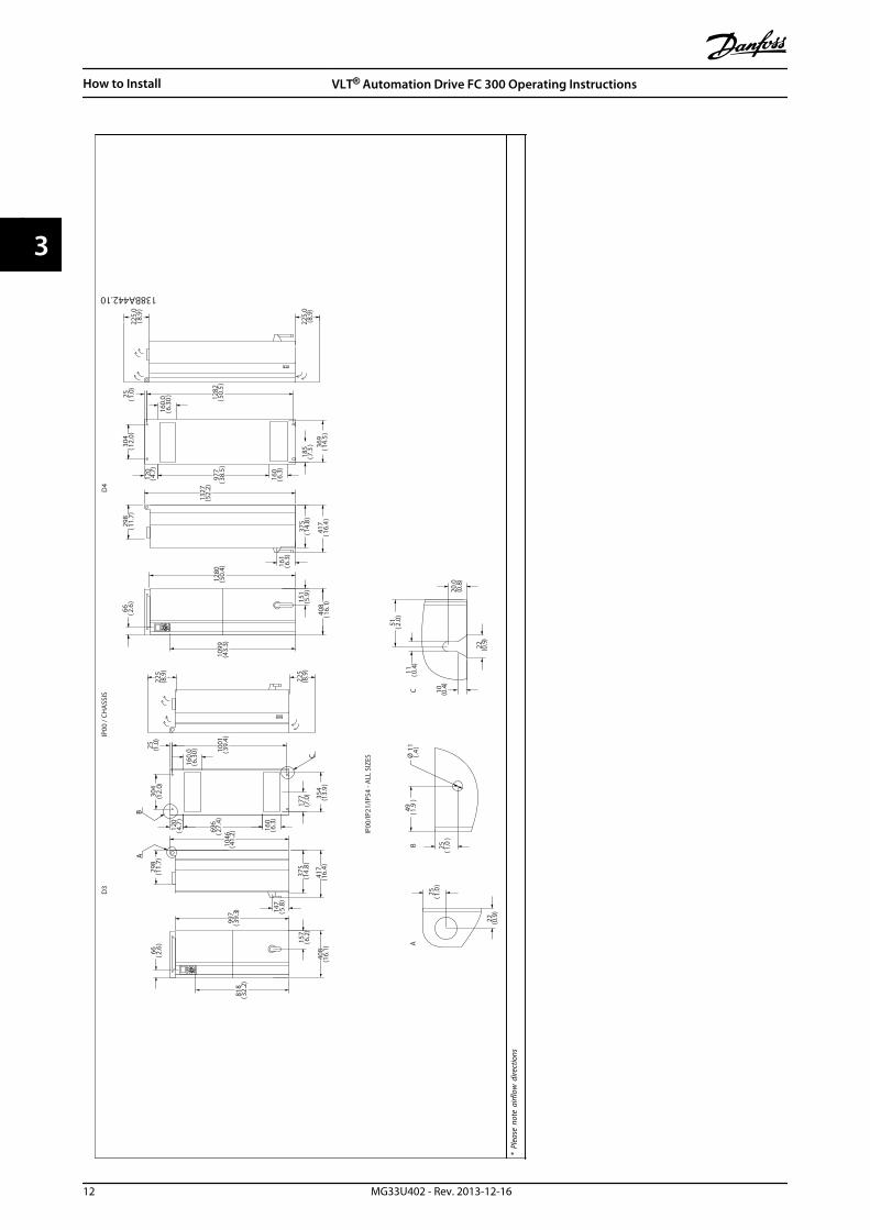
3.1.5 Mechanical Dimensions IP
21 A
ND
IP54
/ U
L A
ND
NEM
A T
YPE
1 A
ND
12
AB
C120
(4.7
)
177.
0(7
.0) 35
4.0
(13.
9)
1166
(45.
9) 310
(12.
2)
163
(6.4
)
420
(16.
5)
981
(38.
6)
74
(2.9
)
417
(16.
4)
380
(15.
0)
D1
D2
130BA443.11
417
(16.
4)
380
(15.
0)22
5
(8.9
)
225
(8
.9)
225.
0(8
.9)
225.
0
(8.9
)
369.
0(1
4.5)
849
(33.
4)12
09(4
7.6) 16
0.0
(6.3
)
160.
0(6
.3)
160.
0(6
.3)
160.
0(6
.3)
304
(12.
0)
304
(12.
0)
25 (1.0
)
25 (1.0
)
1154
(45.
4)
1362
(53.
6)
420
(16.
5)
157
(6.2
)
72 (2.8
)
1547
(60.
9)15
89(6
2.6)
423
(16.
6)
120
(4.7
)
1535
(60.
4)
184.
5(7
.3)
977
(38.
5)
* Pl
ease
not
e ai
rflow
dire
ctio
ns
How to Install VLT® Automation Drive FC 300 Operating Instructions
MG33U402 - Rev. 2013-12-16 11
3 3
AB
C
IP00
/ CH
ASS
IS
IP00
/IP21
/IP54
- A
LL S
IZES
1099
43.3
()
1280
50.4
()
1327
52.2
()
375
14.8
()
417
16.4
()
298
11.7
()
304
12.0
()
120
4.7
()
977
38.5
()
160
6.3
()
185
7.3
() 36
914
.5(
)
1282
50.5
()
25 1.0
()
161
6.3
()
225
(8.
9)
225
(8.9
)
997
39.3
()
818
32.2
()
408
16.1
()
66 2.6
()
408
16.1
()
66 2.6
()
298
11.7
()
375
14.8
()
1046
41.2
()12
04.
7(
)
696
27.4
()
160
6.3
()
100125 1.0
()
39.4
()
304
12.0
()
151
5.9
()
157
6.2
()
147
5.8
()
417
16.4
()
177
7.0
() 35
413
.9(
)
25 1.0
()
22 0.9
()
49 1.9
()
25 1.0
()
Ø11 .4()
20.0
0.8
()
10 0.4
()
51 2.0
()
11 0.4
()
160.
06.
30(
)
160.
06.
30(
)
225.
08.
9(
)
225.
08.
9(
)
D3
D4
BA
C
22 0.9
()
138BA442.10
* Pl
ease
not
e ai
rflow
dire
ctio
ns
How to Install VLT® Automation Drive FC 300 Operating Instructions
12 MG33U402 - Rev. 2013-12-16
33
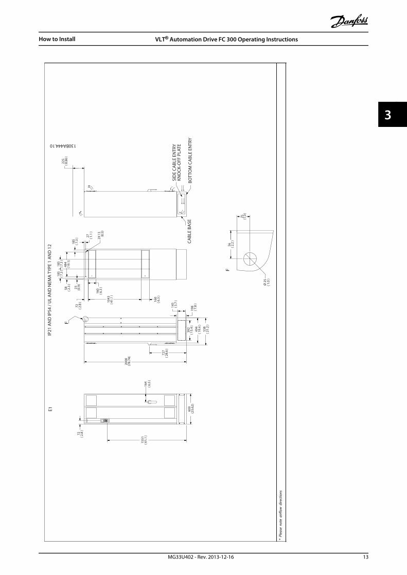
E1
225
8.86
()
1551
61.1
()
2000
(78.
74) 72
728
.6(
)
72 2.8
()
164
600
(23.
62)
198 7.8
()
145 5.7
()
494
19.4
()
392
15.4
()
538
21.2
()
160
6.3
()
1043
41.1
()
160
6.3
()
72 2.8
()
27 1.1
()
23 0.9
()
185
7.3
()
185
7.3
()
58 2.3
()
484
19.1
()
2X13 0.
5(
)
25 1.0
()
56 2.2
()
6.5
()
185
7.3
()
1.0
()
F
F
130BA444.10
SID
E CA
BLE
ENTR
YKN
OCK
-OFF
PLA
TE
CABL
E BA
SEBO
TTO
M C
ABL
E EN
TRY
IP21
AN
D IP
54 /
UL
AN
D N
EMA
TYP
E 1
AN
D 1
2
Ø 2
5
* Pl
ease
not
e ai
rflow
dire
ctio
ns
How to Install VLT® Automation Drive FC 300 Operating Instructions
MG33U402 - Rev. 2013-12-16 13
3 3

130BA445.10
225
64
1320
585
269
156
23
25
498
539
1547
1502
160
104314
184
184
184
139
304
2X13
(2.5
)
(23.
0)
(52.
0)
(6.2
)
(19.
5)
(10.
6)
(21.
2)
(60.
9)
(5.5
)(1
2.0)
(7.3
)(7
.3)
(0.5
)
(1.5
)
120
(4.7
)25 (1
.0)
(59.
1)
(41.
1)
(6.3
)
(8.9
)
225
(8.9
)
(1.0
)25 (1
.0)
(0.9
)
27 (1.0
)
13 (0.5
)
E2
D
E
D
E
IP00
/ CH
ASS
IS
* Pl
ease
not
e ai
rflow
dire
ctio
ns
How to Install VLT® Automation Drive FC 300 Operating Instructions
14 MG33U402 - Rev. 2013-12-16
33

F1IP
21/5
4 -
NEM
A 1
/12
F3IP
21/5
4 -
NEM
A 1
/12
1
130BB027.10
2281
.4(89.82
)
2206
.4(86.87
)
1499
.2(59.02
)
1400
.0(55.12
)ø2
9.0
(1.14)
225.0
(8.85)
607.0
(23.9)
225.
0(8
.85)
1
130BB029.10
2280
(89.
7)
2205
(86.
8)
1497
(58.
9)
1997
(78.
6)ø2
9( 1
.1)
607
(23.
9)
1) M
inim
um c
lear
ance
from
cei
ling
How to Install VLT® Automation Drive FC 300 Operating Instructions
MG33U402 - Rev. 2013-12-16 15
3 3

F2IP
21/5
4 -
NEM
A 1
/12
F4IP
21/5
4 -
NEM
A 1
/12
225.0
(8.85)
2281
(89.8)
1499
(59.0)
Ø29
(1.1)
1804
(71.0)
2206
(86.9)
606
(23.8)
130BB028.10
1
1
130BB030.10
2280
(89.7) 22
05(86.8) 14
97(58.9)
2401
(94.5)
Ø29
(1.1)
225.0
(8.85)
604
(23.8)
1) M
inim
um c
lear
ance
from
cei
ling
How to Install VLT® Automation Drive FC 300 Operating Instructions
16 MG33U402 - Rev. 2013-12-16
33

Frame size D1 D2 D3 D490-110 kW(380-500 V)37-132 kW(525-690 V)
132-200 kW(380-500 V)160-315 kW(525-690 V)
90-110 kW(380-500 V)37-132 kW(525-690 V)
132-200 kW(380-500 V)160-315 kW(525-690 V)
IPNEMA
21Type 1
54Type 12
21Type 1
54Type 12
00Chassis
00Chassis
Shipping dimensions Height 650 650 650 650 650 650Width 1730 1730 1730 1730 1220 1490Depth 570 570 570 570 570 570
Frequency converterdimensions Height 1209 1209 1589 1589 1046 1327
Width 420 420 420 420 408 408Depth 380 380 380 380 375 375Maxweight[kg]
104 104 151 151 91 138
Table 3.1 Mechanical dimensions [mm], frame size D
Frame size E1 E2 F1 F2 F3 F4250-400 kW(380-500 V)355-560 kW(525-690 V)
250-400 kW(380-500 V)355-560 kW(525-690 V)
450-630 kW(380-500 V)630-800 kW(525-690 V)
710-800 kW(380-500 V)
900-1200 kW(525-690 V)
450-630 kW(380-500 V)630-800 kW(525-690 V)
710-800 kW(380-500 V)
900-1200 kW(525-690 V)
IPNEMA
21, 54Type 12
00Chassis
21, 54Type 12
21, 54Type 12
21, 54Type 12
21, 54Type 12
Shippingdimensions
Height 840 831 2324 2324 2324 2324
Width 2197 1705 1569 1962 2159 2559Depth 736 736 1130 1130 1130 1130
Frequencyconverterdimensions
Height 2000 1547 2204 2204 2204 2204
Width 600 585 1400 1800 2000 2400Depth 494 498 606 606 606 606Maxweight 313 277 1004 1246 1299 1541
Table 3.2 Mechanical dimensions [mm], frame sizes E and F
How to Install VLT® Automation Drive FC 300 Operating Instructions
MG33U402 - Rev. 2013-12-16 17
3 3
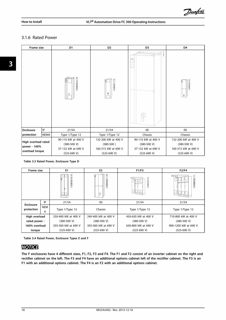
3.1.6 Rated Power
Frame size D1 D2 D3 D4
130B
A81
6.10
130B
A81
7.10
130B
A81
9.10
130B
A82
0.10
Enclosureprotection
IP 21/54 21/54 00 00
NEMA Type 1/Type 12 Type 1/Type 12 Chassis Chassis
High overload ratedpower - 160%overload torque
90-110 kW at 400 V(380-500 V)
37-132 kW at 690 V(525-690 V)
132-200 kW at 400 V(380-500 )
160-315 kW at 690 V(525-690 V)
90-110 kW at 400 V(380-500 V)
37-132 kW at 690 V(525-690 V)
132-200 kW at 400 V(380-500 V)
160-315 kW at 690 V(525-690 V)
Table 3.3 Rated Power, Enclosure Type D
Frame size E1 E2 F1/F3 F2/F4
130B
A81
8.10
130B
A82
1.10
F3 F1
130B
A95
9.10
F4 F2
130B
B092
.11
Enclosureprotection
IP 21/54 00 21/54 21/54
NEMA
Type 1/Type 12 Chassis Type 1/Type 12 Type 1/Type 12
High overloadrated power -
160% overloadtorque
250-400 kW at 400 V(380-500 V)
355-560 kW at 690 V(525-690 V)
240-400 kW at 400 V(380-500 V)
355-560 kW at 690 V(525-690 V)
450-630 kW at 400 V(380-500 V)
630-800 kW at 690 V(525-690 V)
710-800 kW at 400 V(380-500 V)
900-1200 kW at 690 V(525-690 V)
Table 3.4 Rated Power, Enclosure Types E and F
NOTICEThe F enclsoures have 4 different sizes, F1, F2, F3 and F4. The F1 and F2 consist of an inverter cabinet on the right andrectifier cabinet on the left. The F3 and F4 have an additional options cabinet left of the rectifier cabinet. The F3 is anF1 with an additional options cabinet. The F4 is an F2 with an additional options cabinet.
How to Install VLT® Automation Drive FC 300 Operating Instructions
18 MG33U402 - Rev. 2013-12-16
33

3.2 Mechanical Installation
Preparation of the mechanical installation of the frequencyconverter must be done carefully to ensure a proper resultand to avoid additional work during installation. Starttaking a close look at the mechanical drawings at the endof this instruction to become familiar with the spacedemands.
3.2.1 Tools Needed
To perform the mechanical installation the followingtools are needed:
• Drill with 10 or 12 mm drill
• Tape measure
• Wrench with relevant metric sockets (7-17mm)
• Extensions to wrench
• Sheet metal punch for conduits or cable glandsin IP21/Nema 1 and IP54 units
• Lifting bar to lift the unit (rod or tube max. Ø 5mm (1 inch), able to lift minimum 400 kg (880lbs)).
• Crane or other lifting aid to place the frequencyconverter in position
• A Torx T50 tool is needed to install the E1 in IP21and IP54 enclosure types.
3.2.2 General Considerations
Wire accessEnsure that proper cable access is present includingnecessary bending allowance. As the IP00 enclosure isopen to the bottom cables must be fixed to the backpanel of the enclosure where the frequency converter ismounted, i.e. by using cable clamps.
CAUTIONAll cable lugs/shoes must mount within the width of theterminal bus bar.
SpaceEnsure proper space above and below the frequencyconverter to allow airflow and cable access. In additionspace in front of the unit must be considered to enableopening of the door of the panel.
176FA23
5.11
<105,0°
526(20.7)
399(15.7)
Illustration 3.9 Space in Front of IP21/IP54 Rated EnclosureTypes D1 and D2
748(29.5)
579(22.8)
176FA27
6.12
≤105,0°
Illustration 3.10 Space in Front of IP21/IP54 Rated EnclosureType E1
130B
B003
.13
578(22.8)
776(30.6)
Illustration 3.11 Space in Front of IP21/IP54 Rated EnclosureType F1
2X578 [22.8] 776
[30.6]
130B
B004
.13
Illustration 3.12 Space in Front of IP21/IP54 Rated EnclosureType F3
130B
B005
.13
624[24.6]
579[22.8]
578[22.8]
Illustration 3.13 Space in Front of IP21/IP54 Rated EnclosureType F2
How to Install VLT® Automation Drive FC 300 Operating Instructions
MG33U402 - Rev. 2013-12-16 19
3 3
624(24.6)
2x579 (22.8)
578 (22.8)
130B
B006
.10
Illustration 3.14 Space in Front of IP21/IP54 Rated EnclosureType F4
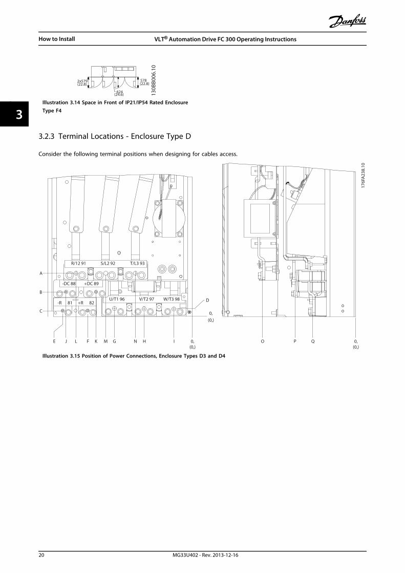
3.2.3 Terminal Locations - Enclosure Type D
Consider the following terminal positions when designing for cables access.
0,(0,)
0,(0,)
O P Q0,(0,)
NMLJ KE F G H I
A
B
C
D
176F
A23
8.10
R/12 91
W/T3 98V/T2 97U/T1 96+R 82-R 81
+DC 89-DC 88
T/L3 93S/L2 92
Illustration 3.15 Position of Power Connections, Enclosure Types D3 and D4
How to Install VLT® Automation Drive FC 300 Operating Instructions
20 MG33U402 - Rev. 2013-12-16
33

R/L1 S/L2
U/T1 96 V/T2 97 W/T398
T/L391
81 82
9392
-DC +DC
-R +R
0,(0,)
UTS
R
0,(0,)
176F
A23
9.10
0,(0,)
V
Illustration 3.16 Position of Power Connections with Disconnect Switch, Enclosure Types D1 and D2
Be aware that the power cables are heavy and hard to bend. Consider the optimum position of the frequency converter forensuring easy installation of the cables.
How to Install VLT® Automation Drive FC 300 Operating Instructions
MG33U402 - Rev. 2013-12-16 21
3 3

NOTICEAll D enclosures are available with standard input terminals or disconnect switch. All terminal dimensions can be foundin Table 3.5.
IP21 (NEMA 1)/IP54 (NEMA 12) IP00/Chassis
D1 D2 D3 D4
A 277 (10.9) 379 (14.9) 119 (4.7) 122 (4.8)
B 227 (8.9) 326 (12.8) 68 (2.7) 68 (2.7)
C 173 (6.8) 273 (10.8) 15 (0.6) 16 (0.6)
D 179 (7.0) 279 (11.0) 20.7 (0.8) 22 (0.8)
E 370 (14.6) 370 (14.6) 363 (14.3) 363 (14.3)
F 300 (11.8) 300 (11.8) 293 (11.5) 293 (11.5)
G 222 (8.7) 226 (8.9) 215 (8.4) 218 (8.6)
H 139 (5.4) 142 (5.6) 131 (5.2) 135 (5.3)
I 55 (2.2) 59 (2.3) 48 (1.9) 51 (2.0)
J 354 (13.9) 361 (14.2) 347 (13.6) 354 (13.9)
K 284 (11.2) 277 (10.9) 277 (10.9) 270 (10.6)
L 334 (13.1) 334 (13.1) 326 (12.8) 326 (12.8)
M 250 (9.8) 250 (9.8) 243 (9.6) 243 (9.6)
N 167 (6.6) 167 (6.6) 159 (6.3) 159 (6.3)
O 261 (10.3) 260 (10.3) 261 (10.3) 261 (10.3)
P 170 (6.7) 169 (6.7) 170 (6.7) 170 (6.7)
Q 120 (4.7) 120 (4.7) 120 (4.7) 120 (4.7)
R 256 (10.1) 350 (13.8) 98 (3.8) 93 (3.7)
S 308 (12.1) 332 (13.0) 301 (11.8) 324 (12.8)
T 252 (9.9) 262 (10.3) 245 (9.6) 255 (10.0)
U 196 (7.7) 192 (7.6) 189 (7.4) 185 (7.3)
V 260 (10.2) 273 (10.7) 260 (10.2) 273 (10.7)
Table 3.5 Cable Positions Dimensions in mm (inch)
How to Install VLT® Automation Drive FC 300 Operating Instructions
22 MG33U402 - Rev. 2013-12-16
33

3.2.4 Terminal Locations - E Enclosures
Terminal Locations - E1Take the following position of the terminals into consideration when designing the cable access.
176FA27
8.10
0[0.0]
0[0.0]
600[23.6]
525[20.7]
412[16.2]
300[11.8]
188[7.4]
75[3.0]
B
492[19.4]
323[12.7]
195[7.7]
0[0.0]
155[6.1]
193[7.6]
280[11.0]
371[14.6]
409[16.1]
Illustration 3.17 IP21 (NEMA Type 1) and IP54 (NEMA Type 12) Enclosure Power Connection Positions
How to Install VLT® Automation Drive FC 300 Operating Instructions
MG33U402 - Rev. 2013-12-16 23
3 3

176F
A27
2.10
0[0.
0]
55[2
.2]
91[3
.6]
139[
5.5]
175[
6.9]
0[0.0]
453[17.8]
B
A A A A-R 81
9
19 Nm [14 FTa
Illustration 3.18 IP21 (NEMA type 1) and IP54 (NEMA type 12)Enclosure Power Connection Positions (Detail B)
How to Install VLT® Automation Drive FC 300 Operating Instructions
24 MG33U402 - Rev. 2013-12-16
33

E
F
BCD
00.0
[]
512.0
[]
226
8.9
[]
266
10.5
[]
441
17.4
[]
0 0.0[ ]28 1.1[ ]
167 6.6[ ]195 7.7[ ]
A
00.0
[]
176FA27
9.11
Illustration 3.19 IP21 (NEMA type 1) and IP54 (NEMA type 12) Enclosure Power Connection Position of Disconnect Switch
Enclosuretypes
Unit type Dimensions [mm]/(inch)
E1
IP54/IP21 UL AND NEMA1/NEMA12
250/315 kW (400 V) AND 355/450-500/630KW (690 V)
396 (15.6) 267 (10.5) 332 (13.1) 397 (15.6) 528 (20.8) N/A
315/355-400/450 kW (400 V) 408 (16.1) 246 (9.7) 326 (12.8) 406 (16.0) 419 (16.5) 459 (18.1)
Table 3.6 Dimensions for Disconnect Terminal
How to Install VLT® Automation Drive FC 300 Operating Instructions
MG33U402 - Rev. 2013-12-16 25
3 3

Terminal locations - enclosure type E2Take the following position of the terminals into consideration when designing the cable access.
176F
A28
0.10
58
5[2
3.0
]
51
8[2
0.4
]
40
5[1
5.9
]
68
[2.7
]
0[0.0]
186[7.3]
0[0
.0]
0[0
.0]
18
1[7
.1]
29
3[1
1.5
]
40
9[1
6.1
]
37
1[1
4.6
]
28
0[1
1.0
]
19
2[7
.6]
15
4[6
.1]
17[0.7]
A
R/L1 91
9
S/L2 92
U/T1 96 V/T2 97
T/L3 93
W/T3 98
FASTENER TORQUE M8 9.6 Nm (7 FT-LB) FASTENER TORQUE M8 9.6 Nm (7 FT-LB)
Illustration 3.20 IP00 Enclosure Power Connection Positions17
6FA
282.
10
0(0
.0)
47
(1.9
)
83
(3.3
)
13
1(5
.2)
16
7(6
.6)
0(0.0)
147(5.8)
A A A A019Nm (14 F)
9
A
R 81
Illustration 3.21 IP00 Enclosure Power Connection Positions
How to Install VLT® Automation Drive FC 300 Operating Instructions
26 MG33U402 - Rev. 2013-12-16
33

E
00.0[ ]
F
B
00.0
[]CD A
00.0
[]
176FA28
1.11
Illustration 3.22 IP00 Enclosure Power Connections Positions of Disconnect Switch
NOTICEThe power cables are heavy and difficult to bend. Consider the optimum position of the frequency converter forensuring easy installation of the cables.Each terminal allows use of up to 4 cables with cable lugs or use of standard box lug. Earth is connected to relevanttermination point in the frequency converter.If lugs are wider than 39 mm, install supplied barriers on the mains input side of the disconnect.
104[4.1]
35[1.4]
10[0.4]0[0.0]
0[0.0]
40[1.6]
78[3.1]
0[0.0]
26[1.0]
26[1.0]
176FA27
1.10
Illustration 3.23 Terminal in Details
How to Install VLT® Automation Drive FC 300 Operating Instructions
MG33U402 - Rev. 2013-12-16 27
3 3

NOTICEPower connections can be made to positions A or B
Enclosuretype
Unit type Dimensions [mm]/(inch)
E2
IPOO/CHASSIS A B C D E F
250/315 kW (400 V) AND 355/450-500/630KW (690 V)
396 (15.6) 268 (10.6) 333 (13.1) 398 (15.7) 221 (8.7) N/A
315/355-400/450 kW (400 V) 408 (16.1) 239 (9.4) 319 (12.5) 399 (15.7) 113 (4.4) 153 (6.0)
Table 3.7 Dimensions for Disconnect Terminal
3.2.5 Terminal Locations - Frame size F
NOTICEThe F frames have 4 different sizes, F1, F2, F3 and F4. The F1 and F2 consist of an inverter cabinet on the right andrectifier cabinet on the left. The F3 and F4 have an additional options cabinet left of the rectifier cabinet. The F3 is anF1 with an additional options cabinet. The F4 is an F2 with an additional options cabinet.
Terminal locations - Frame size F1 and F3
130B
A84
9.13
.0 [.
0]54
.4[2
.1]
169.
4[6
.7]
284.
4[1
1.2]
407.
3[1
6.0]
522.
3[2
0.6]
637.
3[2
5.1]
287.
4[1
1.3]
253.1 [10.0]
.0[.0
]
.0 [.0]
339.
4[1
3.4]
287.
4[1
1.3]
.0[.0
]
339.
4[1
3.4]
308.3 [12.1]
465.
6[1
8.3]
465.
6[1
8.3]
198.
1[7.
8]23
4.1
[9.2
]28
2.1
[11.
1]31
8.1
[12.
5]
551.
0[2
1.7]
587.
0[2
3.1]
635.
0[2
5.0]
671.
0[2
6.4]
44.40 [1.75]
244.40 [9.62]
204.
1 [8
.0]
497.
1[1
9.6]
572.
1[2
2.5]
180.3 [7.1]
129.
1 [5
.1] 4
6
4
1 23
5
Illustration 3.24 Terminal locations - Inverter Cabinet - F1 and F3 (front, left and right side view). The gland plate is 42 mm below .0level.1) Earth ground bar2) Motor terminals3) Brake terminals
How to Install VLT® Automation Drive FC 300 Operating Instructions
28 MG33U402 - Rev. 2013-12-16
33
S1 F1
F1
DC ‘-’
DC ‘+’
1739.1
805.0
765.0
1694.1
1654.1
710.0
130B
B377
.10
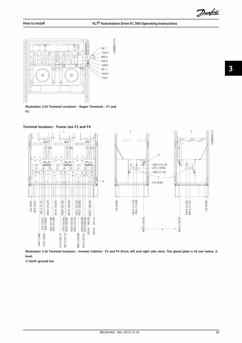
Illustration 3.25 Terminal Locations - Regen Terminals - F1 andF3
Terminal locations - Frame size F2 and F4
287.
4[1
1.32
]
0.0
[0.0
0]
339.
4[1
3.36
]
253.1 [9.96]
0.0 [0.00]
287.
4[1
1.32
]
0.0
[0.0
0]
339.
4[1
3.36
]
465.
6[1
8.33
]
465.
6[1
8.33
]
308.3 [12.14]
180.3 [7.10]
210.
1[8
.27]
0.0
[0.0
0]66
.4[2
.61]
181.
4[7
.14]
296.
4[1
1.67
]
431.
0[1
6.97
]
546.
0[2
1.50
]
661.
0[2
6.03
]
795.
7[3
1.33
]91
0.7
[35.
85]
1025
.7[4
0.38
]
246.
1[9
.69]
294.
1[1
1.58
]33
0.1
[13.
00]
574.
7[2
2.63
]61
0.7
[24.
04]
658.
7[2
5.93
]69
4.7
[27.
35]
939.
4[3
6.98
]97
5.4
[38.
40]
1023
.4[4
0.29
]
1059
.4[4
1.71
]
144.
3[5
.68]
219.
3[8
.63]
512.
3[2
0.17
]
587.
3[2
3.12
]
880.
3[3
4.66
]
955.
3[3
7.61
]
6
4
130B
A85
0.12
FASTENER TORQUE: MIO 19 Nm (14 FT -LB)
U/T1 96 V/T2 97 W/T3 98FASTENER TORQUE: MIO 19 Nm (14 FT -LB)
U/T1 96 V/T2 97 W/T3 98FASTENER TORQUE: MIO 19 Nm (14 FT -LB)
U/T1 96 V/T2 97 W/T3 98
1 2 3
4
5
Illustration 3.26 Terminal locations - Inverter Cabinet - F2 and F4 (front, left and right side view). The gland plate is 42 mm below .0level.1) Earth ground bar
How to Install VLT® Automation Drive FC 300 Operating Instructions
MG33U402 - Rev. 2013-12-16 29
3 3

S1S2S2
F1F1
S2F1
DC ‘-’
DC ‘+’
1739.11203.21163.21694.1
1654.11098.1
130B
B378
.10
Illustration 3.27 Terminal Locations - Regen Terminals - F2 andF4
Terminal locations - Rectifier (F1, F2, F3 and F4)74
.6 [2
.9]
0.0
[0.0
]
125.
8 [4
.95]
218.
6 [8
.61]
293.
6 [1
1.56
]
362.
6 [1
4.28
]
437.
6 [1
7.23
]
149.
6 [5
.89]
486.
6 [1
9.16
]
183.
4 [7
.22]
373.
4 [1
4.70
]
0.0 [0.00]
70.4 [2.77]
193.9 [7.64]
343.1 [13.51]
38.1
[1.5
0]0.
0 [0
.00]
90.1
[3.5
5]13
6.6
[5.3
8]18
8.6
[7.4
2] B A
435.5 [17.15]
LOAD SHARE LOCATIONDIM F1/F2 F3/F4
A 380.5 [14.98] 29.4 [1.16]B 432.5 [17.03] 81.4 [3.20]
6
5
4
130B
A84
8.12
CH22 CH22
R/L1 91 S/L2 92FASTENER TORQUE: M8 9.6 Nm (7 FT-LB)
T/L3 93FASTENER TORQUE: M10 19 Nm (14 FT-LB)
FASTENER TORQUE: M10 19 Nm (14 FT-LB)DC 89
FASTENER TORQUE: M10 19 Nm (14 FT-LB)DC 89
CH22 CH22 CH22 CH22CTI25MB CTI25MB
AUXAUX AUXAUXAUX
321
Illustration 3.28 Terminal locations - Rectifier (Left side, front and right side view). The gland plate is 42 mm below .0 level.1) Loadshare Terminal (-)2) Earth ground bar3) Loadshare Terminal (+)
How to Install VLT® Automation Drive FC 300 Operating Instructions
30 MG33U402 - Rev. 2013-12-16
33

Terminal locations - Options Cabinet (F3 and F4)1 2 3
4
0.0[0.00
]76
.4[3.01]
128.4[5.05
]11
9.0[4.69
]17
1.0[6.73
]
294.6[11
.60]
344.0[13
.54]
3639
[14.33
]43
8.9[17
.28]
75.3[2.96]
150.3[5.92
]15
4.0[6.06
]
219.6[18
.65]
0.0[0.00
]
244.4[9.62]
244.4[1.75]
939.0[36.97]
1031.4[40.61]
0.0[0.00]
134.6[5.30]
130B
A85
1.12
0.0[1.75]
Illustration 3.29 Terminal locations - Options Cabinet (Left side, front and right side view). The gland plate is 42 mm below .0 level.1) Earth ground bar
Terminal locations - Options Cabinet with circuit breaker/ molded case switch (F3 and F4)
0.0 [0.00]
134.6 [5.30]
104.
3 [4
.11]
0.0
[0.0
0]
179.
3 [7
.06]
219.
6 [8
.65]
294.
6 [1
1.60
]
334.
8 [1
3.18
]40
9.8
[16.
14]
436.9 [17.20]
0.0 [0.00]
532.9 [20.98]
0.0
[0.0
0]
44.4 [1.75]
244.4 [9.62]
154.
0 [6
.06]
344.
0 [1
3.54
]
1
2
3
4
5
130B
A85
2.11
Illustration 3.30 Terminal locations - Options Cabinet with circuit breaker/ molded case switch (Left side, front and right side view).The gland plate is 42 mm below .0 level.1) Earth ground bar
How to Install VLT® Automation Drive FC 300 Operating Instructions
MG33U402 - Rev. 2013-12-16 31
3 3
Power size 2 3 4 5
450 kW (480 V), 630-710 kW(690 V)
34.9 86.9 122.2 174.2
500-800 kW (480 V),800-1000 kW (690 V)
46.3 98.3 119.0 171.0
Table 3.8 Dimension for Terminal
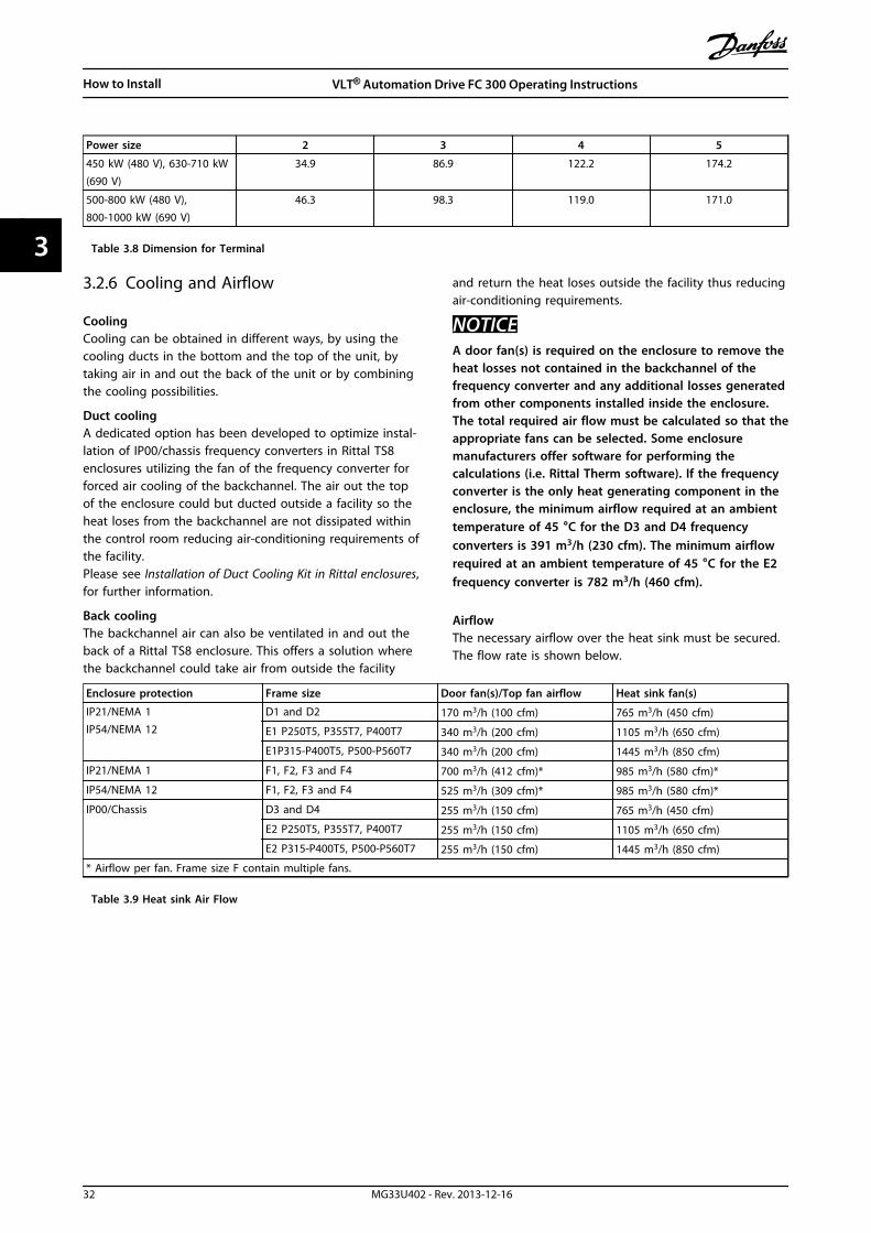
3.2.6 Cooling and Airflow
CoolingCooling can be obtained in different ways, by using thecooling ducts in the bottom and the top of the unit, bytaking air in and out the back of the unit or by combiningthe cooling possibilities.
Duct coolingA dedicated option has been developed to optimize instal-lation of IP00/chassis frequency converters in Rittal TS8enclosures utilizing the fan of the frequency converter forforced air cooling of the backchannel. The air out the topof the enclosure could but ducted outside a facility so theheat loses from the backchannel are not dissipated withinthe control room reducing air-conditioning requirements ofthe facility.Please see Installation of Duct Cooling Kit in Rittal enclosures,for further information.
Back coolingThe backchannel air can also be ventilated in and out theback of a Rittal TS8 enclosure. This offers a solution wherethe backchannel could take air from outside the facility
and return the heat loses outside the facility thus reducingair-conditioning requirements.
NOTICEA door fan(s) is required on the enclosure to remove theheat losses not contained in the backchannel of thefrequency converter and any additional losses generatedfrom other components installed inside the enclosure.The total required air flow must be calculated so that theappropriate fans can be selected. Some enclosuremanufacturers offer software for performing thecalculations (i.e. Rittal Therm software). If the frequencyconverter is the only heat generating component in theenclosure, the minimum airflow required at an ambienttemperature of 45 °C for the D3 and D4 frequencyconverters is 391 m3/h (230 cfm). The minimum airflowrequired at an ambient temperature of 45 °C for the E2frequency converter is 782 m3/h (460 cfm).
AirflowThe necessary airflow over the heat sink must be secured.The flow rate is shown below.
Enclosure protection Frame size Door fan(s)/Top fan airflow Heat sink fan(s)
IP21/NEMA 1IP54/NEMA 12
D1 and D2 170 m3/h (100 cfm) 765 m3/h (450 cfm)
E1 P250T5, P355T7, P400T7 340 m3/h (200 cfm) 1105 m3/h (650 cfm)
E1P315-P400T5, P500-P560T7 340 m3/h (200 cfm) 1445 m3/h (850 cfm)
IP21/NEMA 1 F1, F2, F3 and F4 700 m3/h (412 cfm)* 985 m3/h (580 cfm)*
IP54/NEMA 12 F1, F2, F3 and F4 525 m3/h (309 cfm)* 985 m3/h (580 cfm)*
IP00/Chassis D3 and D4 255 m3/h (150 cfm) 765 m3/h (450 cfm)
E2 P250T5, P355T7, P400T7 255 m3/h (150 cfm) 1105 m3/h (650 cfm)
E2 P315-P400T5, P500-P560T7 255 m3/h (150 cfm) 1445 m3/h (850 cfm)
* Airflow per fan. Frame size F contain multiple fans.
Table 3.9 Heat sink Air Flow
How to Install VLT® Automation Drive FC 300 Operating Instructions
32 MG33U402 - Rev. 2013-12-16
33

NOTICEThe fan runs for the following reasons:
• AMA
• DC Hold
• Pre-Mag
• DC Brake
• 60% of nominal current is exceeded
• Specific heatsink temperature exceeded (powersize dependent).
• Specific Power Card ambient temperatureexceeded (power size dependent)
• Specific Control Card ambient temperatureexceeded
Once the fan is started it runs for minimum 10 minutes.
External ductsIf additional duct work is added externally to the Rittalcabinet the pressure drop in the ducting must becalculated. Use the charts below to derate the frequencyconverter according to the pressure drop.
90
80
70
60
50
40
30
20
10
0 0 0.5 4.9 13 27.3 45.9 66 89.3 115.7 147
(%)
(Pa)Pressure Increase
Driv
e D
erat
ing
130B
B007
.10
Illustration 3.31 D frame Derating vs. Pressure Change
Drive air flow: 450 cfm (765 m3/h)
90
80
70
60
50
40
30
20
10
0
(%)
Driv
e D
erat
ing
0 0 0.1 3.6 9.8 21.5 43.4 76 237.5 278.9(Pa)Pressure Change
130B
B010
.10
147.1
Illustration 3.32 E frame Derating vs. Pressure Change (SmallFan), P250T5 and P355T7-P400T7
Drive air flow: 650 cfm (1105 m3/h)
90
80
70
60
50
40
30
20
10
0
(%)D
rive
Der
atin
g
0 0.2 0.6 2.2 5.8 11.4 18.1 30.8 152.8 210.8(Pa)Pressure Change
130B
B011
.10
69.5
Illustration 3.33 E frame Derating vs. Pressure Change (LargeFan), P315T5-P400T5 and P500T7-P560T7
Drive air flow: 850 cfm (1445 m3/h)
90
80
70
60
50
40
30
20
10
0
(%)
Driv
e D
erat
ing
0 25 50 75 100 125 150 175 225
130B
B190
.10
200
Pressure Change
Illustration 3.34 F1, F2, F3, F4 frame Derating vs. PressureChange
Drive air flow: 580 cfm (985 m3/h)
How to Install VLT® Automation Drive FC 300 Operating Instructions
MG33U402 - Rev. 2013-12-16 33
3 3

3.2.7 Installation on the Wall - IP21 (NEMA1) and IP54 (NEMA 12) Units
This only applies to enclosure types D1 and D2. It must beconsidered where to install the unit.
Take the relevant points into consideration beforeselecting the final installation site:
• Free space for cooling
• Access to open the door
• Cable entry from the bottom
Mark the mounting holes carefully using the mountingtemplate on the wall and drill the holes as indicated.Ensure proper distance to the floor and the ceiling forcooling. A minimum of 225 mm (8.9 inch) below thefrequency converter is needed. Mount the bolts at thebottom and lift the frequency converter up on the bolts.Tilt the frequency converter against the wall and mountthe upper bolts. Tighten all 4 bolts to secure the frequencyconverter against the wall.
176FA24
5.10
Illustration 3.35 Lifting Method for Mounting FrequencyConverter on Wall
3.2.8 Gland/Conduit Entry - IP21 (NEMA 1)and IP54 (NEMA12)
Cables are connected through the gland plate from thebottom. Remove the plate and plan where to place theentry for the glands or conduits. Prepare holes in themarked area on the drawing.
NOTICEThe gland plate must be fitted to the frequencyconverter to ensure the specified protection degree, aswell as ensuring proper cooling of the unit. If the glandplate is not mounted, the frequency converter may tripon Alarm 69, Pwr. Card Temp
130B
B073
.10
Illustration 3.36 Example of Proper Installation of Gland Plate.
Cable entries viewed from the bottom of the frequencyconverter - 1) Mains side 2) Motor side
21
176FA28
9.12
35
350
202.8
98.6
130.0
62.5
Illustration 3.37 Enclosure Types D1 + D2
How to Install VLT® Automation Drive FC 300 Operating Instructions
34 MG33U402 - Rev. 2013-12-16
33

21
176FA28
9.12
35
350
202.8
98.6
130.0
62.5
Illustration 3.38 Enclosure Type E1
Enclosure types F1-F4: Cable entries viewed from thebottom of the frequency converter - 1) Place conduits inmarked areas
1
130B
A83
7.12
1328.8(52.315)
595.8(23.457)
533.0(20.984)36.2
(1.425)
281.8(11.096)
535.0(21.063)
216.5(8.524)
37.7(1.485) 460.0
(18.110)
668.3(26.311)
593.0(23.346)
199.5(7.854)
258.5(10.177)
35.5(1.398)
Illustration 3.39 Enclosure Type F1
533.0[20.984]594.8[23.417] 1727.8
[68.024]
35.5[1.398]
[21.063]258.2[10.167]
199.5[7.854]
37.7[1.485]
460.0[18.110]
994.3[39.146]
216.5[8.524]
36.2[1.425]
281.8[11.096]
1
130B
A84
1.12
535.0
655.925.825
Illustration 3.40 Enclosure Type F2
1
130B
A84
3.12
37.7(1.485)
535.0(21.063)
35.5(1.398)
36.2(1.425)
533.0(20.984)
597.0(23.504)1130.0
(44.488)1192.8
(46.961)1925.8
(75.819)
258.5(10.177)
199.5(7.854)
2X 460.0(18.110)
634.7(24.989)
1265.3(49.815)
593.0(23.346)
2X 281.3(11.075)
2X 216.5(8.524)
Illustration 3.41 Enclosure Type F313
0BA
839.
10
1
37.7(1.485)
533 (20.984)597.0 (23.504)
1130.0 (44.488)
2324.8 (91.528)
535.0(21.063)
2X 216.5(8.524)
2X 460.0(18.110)
634.7 (24.989)
35.5(1.398)
258.2(10.167)
199.5(7.854)
1252.8(49.321)
994.3(39.146)
2X 281.8(11.096)
36.2(1.425)
1191.8 (46.921)
Illustration 3.42 Enclosure Type F4
How to Install VLT® Automation Drive FC 300 Operating Instructions
MG33U402 - Rev. 2013-12-16 35
3 3
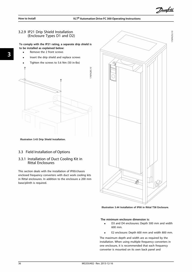
3.2.9 IP21 Drip Shield Installation(Enclosure Types D1 and D2)
To comply with the IP21 rating, a separate drip shield isto be installed as explained below:
• Remove the 2 front screws
• Insert the drip shield and replace screws
• Tighten the screws to 5.6 Nm (50 in-lbs)
176FA28
5.10
Illustration 3.43 Drip Shield Installation.
3.3 Field Installation of Options
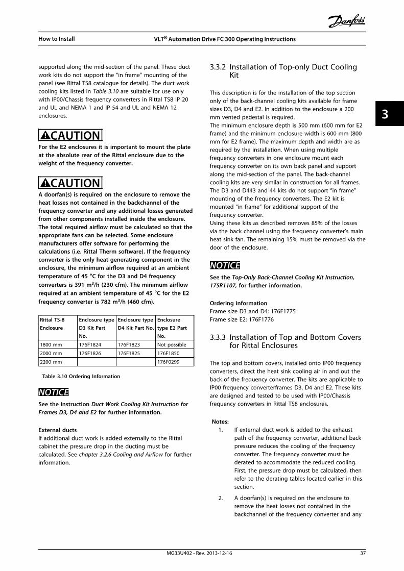
3.3.1 Installation of Duct Cooling Kit inRittal Enclosures
This section deals with the installation of IP00/chassisenclosed frequency converters with duct work cooling kitsin Rittal enclosures. In addition to the enclosure a 200 mmbase/plinth is required.
176FA25
2.10
Illustration 3.44 Installation of IP00 in Rittal TS8 Enclosure.
The minimum enclosure dimension is:• D3 and D4 enclosures: Depth 500 mm and width
600 mm.
• E2 enclosure: Depth 600 mm and width 800 mm.
The maximum depth and width are as required by theinstallation. When using multiple frequency converters inone enclosure, it is recommended that each frequencyconverter is mounted on its own back panel and
How to Install VLT® Automation Drive FC 300 Operating Instructions
36 MG33U402 - Rev. 2013-12-16
33
supported along the mid-section of the panel. These ductwork kits do not support the “in frame” mounting of thepanel (see Rittal TS8 catalogue for details). The duct workcooling kits listed in Table 3.10 are suitable for use onlywith IP00/Chassis frequency converters in Rittal TS8 IP 20and UL and NEMA 1 and IP 54 and UL and NEMA 12enclosures.
CAUTIONFor the E2 enclosures it is important to mount the plateat the absolute rear of the Rittal enclosure due to theweight of the frequency converter.
CAUTIONA doorfan(s) is required on the enclosure to remove theheat losses not contained in the backchannel of thefrequency converter and any additional losses generatedfrom other components installed inside the enclosure.The total required airflow must be calculated so that theappropriate fans can be selected. Some enclosuremanufacturers offer software for performing thecalculations (i.e. Rittal Therm software). If the frequencyconverter is the only heat generating component in theenclosure, the minimum airflow required at an ambienttemperature of 45 °C for the D3 and D4 frequencyconverters is 391 m3/h (230 cfm). The minimum airflowrequired at an ambient temperature of 45 °C for the E2frequency converter is 782 m3/h (460 cfm).
Rittal TS-8Enclosure
Enclosure typeD3 Kit PartNo.
Enclosure typeD4 Kit Part No.
Enclosuretype E2 PartNo.
1800 mm 176F1824 176F1823 Not possible
2000 mm 176F1826 176F1825 176F1850
2200 mm 176F0299
Table 3.10 Ordering Information
NOTICESee the instruction Duct Work Cooling Kit Instruction forFrames D3, D4 and E2 for further information.
External ductsIf additional duct work is added externally to the Rittalcabinet the pressure drop in the ducting must becalculated. See chapter 3.2.6 Cooling and Airflow for furtherinformation.
3.3.2 Installation of Top-only Duct CoolingKit
This description is for the installation of the top sectiononly of the back-channel cooling kits available for framesizes D3, D4 and E2. In addition to the enclosure a 200mm vented pedestal is required.The minimum enclosure depth is 500 mm (600 mm for E2frame) and the minimum enclosure width is 600 mm (800mm for E2 frame). The maximum depth and width are asrequired by the installation. When using multiplefrequency converters in one enclosure mount eachfrequency converter on its own back panel and supportalong the mid-section of the panel. The back-channelcooling kits are very similar in construction for all frames.The D3 and D443 and 44 kits do not support “in frame”mounting of the frequency converters. The E2 kit ismounted “in frame” for additional support of thefrequency converter.Using these kits as described removes 85% of the lossesvia the back channel using the frequency converter’s mainheat sink fan. The remaining 15% must be removed via thedoor of the enclosure.
NOTICESee the Top-Only Back-Channel Cooling Kit Instruction,175R1107, for further information.
Ordering informationFrame size D3 and D4: 176F1775Frame size E2: 176F1776
3.3.3 Installation of Top and Bottom Coversfor Rittal Enclosures
The top and bottom covers, installed onto IP00 frequencyconverters, direct the heat sink cooling air in and out theback of the frequency converter. The kits are applicable toIP00 frequency converterframes D3, D4 and E2. These kitsare designed and tested to be used with IP00/Chassisfrequency converters in Rittal TS8 enclosures.
Notes:1. If external duct work is added to the exhaust
path of the frequency converter, additional backpressure reduces the cooling of the frequencyconverter. The frequency converter must bederated to accommodate the reduced cooling.First, the pressure drop must be calculated, thenrefer to the derating tables located earlier in thissection.
2. A doorfan(s) is required on the enclosure toremove the heat losses not contained in thebackchannel of the frequency converter and any
How to Install VLT® Automation Drive FC 300 Operating Instructions
MG33U402 - Rev. 2013-12-16 37
3 3

additional losses generated from othercomponents installed inside the enclosure. Thetotal required airflow must be calculated so thatthe appropriate fans can be selected. Someenclosure manufacturers offer software forperforming the calculations (i.e. Rittal Thermsoftware).If the frequency converter is the only heatgenerating component in the enclosure, theminimum airflow required at an ambienttemperature of 45 °C for the D3 and D4 framefrequency converter is 391 m3/h (230 cfm). Theminimum airflow required at an ambienttemperature of 45 °C for the E2 frame frequencyconverter is 782 m3/h (460 cfm).
NOTICESee the instruction for Top and Bottom Covers - RittalEnclosure, 177R0076, for further information.
Ordering informationFrame size D3: 176F1781Frame size D4: 176F1782Frame size E2: 176F1783
3.3.4 Installation of Top and Bottom Covers
Top and bottom covers can be installed on frame sizes D3,D4 and E2. These kits are designed to be used to directthe back-channel airflow in and out the back of thefrequency converter as opposed to in the bottom and outthe top of the frequency converter (when the frequencyconverters are being mounted directly on a wall or inside awelded enclosure).
Notes:1. If external duct work is added to the exhaust
path of the frequency converter, additional backpressure reduces the cooling of the frequencyconverter. The frequency converter must bederated to accommodate the reduced cooling.First, the pressure drop must be calculated, thenrefer to the derating tables located earlier in thissection.
2. A doorfan(s) is required on the enclosure toremove the heat losses not contained in thebackchannel of the frequency converter and anyadditional losses generated from othercomponents installed inside the enclosure. Thetotal required airflow must be calculated so thatthe appropriate fans can be selected. Someenclosure manufacturers offer software forperforming the calculations (i.e. Rittal Thermsoftware).
If the frequency converter is the only heatgenerating component in the enclosure, theminimum airflow required at an ambienttemperature of 45 °C for the D3 and D4 framefrequency converters is 391 m3/h (230 cfm). Theminimum airflow required at an ambienttemperature of 45 °C for the E2 frame frequencyconverter is 782 m3/h (460 cfm).
NOTICESee the Top and Bottom Covers Only Instruction,175R1106, for further information.
Ordering informationFrame size D3 and D4: 176F1862Frame size E2: 176F1861
3.3.5 Outside Installation/NEMA 3R Kit forRittal Enclosures
176FT2
61.10
Illustration 3.45
This section is for the installation of NEMA 3R kits availablefor the frequency converter enclosure types D3, D4 and E2.These kits are designed and tested to be used with IP00/Chassis versions of these enclosure types in Rittal TS8NEMA 3R or NEMA 4 enclosures. The NEMA-3R enclosure isan outdoor enclosure that provides a degree of protectionagainst rain and ice. The NEMA-4 enclosure is an outdoor
How to Install VLT® Automation Drive FC 300 Operating Instructions
38 MG33U402 - Rev. 2013-12-16
33
enclosure that provides a greater degree of protectionagainst weather and hosed water.The minimum enclosure depth is 500 mm (600 mm forenclosure type E2) and the kit is designed for a 600 mm(800 mm for enclosure type E2) wide enclosure. Otherenclosure widths are possible, however additional Rittalhardware is required. The maximum depth and width areas required by the installation.
NOTICEThe current rating of frequency converters in enclosuretypes D3 and D4 are de-rated by 3%, when adding theNEMA 3R kit. Frequency converters in enclosure type E2require no derating.
NOTICEA doorfan(s) is required on the enclosure to remove theheat losses not contained in the backchannel of thefrequency converter and any additional losses generatedfrom other components installed inside the enclosure.The total required airflow must be calculated so that theappropriate fans can be selected. Some enclosuremanufacturers offer software for performing thecalculations (i.e. Rittal Therm software). If the frequencyconverter is the only heat generating component in theenclosure, the minimum airflow required at an ambienttemperature of 45 °C for the D3 and D4 frequencyconverters is 391 m3/h (230 cfm). The minimum airflowrequired at an ambient temperature of 45 °C for the E2frequency converter is 782 m3/h (460 cfm).
Ordering informationEnclosure type D3: 176F4600Enclosure type D4: 176F4601Enclosure type E2: 176F1852
NOTICESee the instructions Installation of NEMA 3R Kit for IP00Frames D3, D4 & E2 for further information.
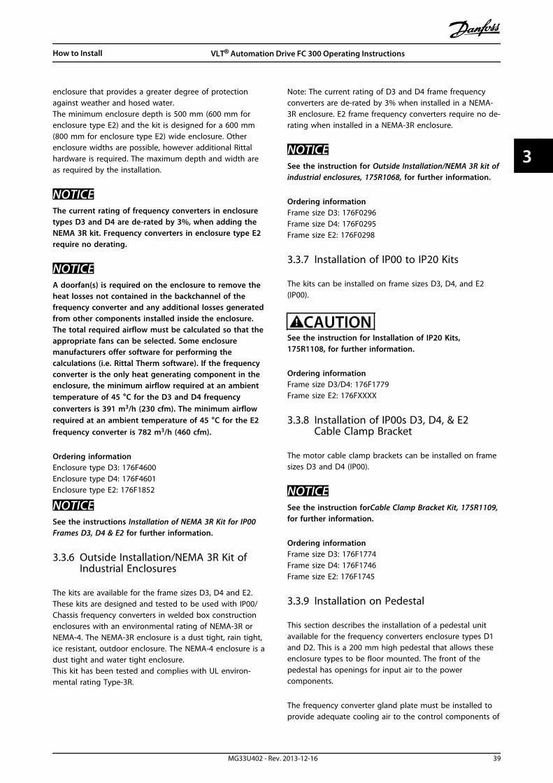
3.3.6 Outside Installation/NEMA 3R Kit ofIndustrial Enclosures
The kits are available for the frame sizes D3, D4 and E2.These kits are designed and tested to be used with IP00/Chassis frequency converters in welded box constructionenclosures with an environmental rating of NEMA-3R orNEMA-4. The NEMA-3R enclosure is a dust tight, rain tight,ice resistant, outdoor enclosure. The NEMA-4 enclosure is adust tight and water tight enclosure.This kit has been tested and complies with UL environ-mental rating Type-3R.
Note: The current rating of D3 and D4 frame frequencyconverters are de-rated by 3% when installed in a NEMA-3R enclosure. E2 frame frequency converters require no de-rating when installed in a NEMA-3R enclosure.
NOTICESee the instruction for Outside Installation/NEMA 3R kit ofindustrial enclosures, 175R1068, for further information.
Ordering informationFrame size D3: 176F0296Frame size D4: 176F0295Frame size E2: 176F0298
3.3.7 Installation of IP00 to IP20 Kits
The kits can be installed on frame sizes D3, D4, and E2(IP00).
CAUTIONSee the instruction for Installation of IP20 Kits,175R1108, for further information.
Ordering informationFrame size D3/D4: 176F1779Frame size E2: 176FXXXX
3.3.8 Installation of IP00s D3, D4, & E2Cable Clamp Bracket
The motor cable clamp brackets can be installed on framesizes D3 and D4 (IP00).
NOTICESee the instruction forCable Clamp Bracket Kit, 175R1109,for further information.
Ordering informationFrame size D3: 176F1774Frame size D4: 176F1746Frame size E2: 176F1745
3.3.9 Installation on Pedestal
This section describes the installation of a pedestal unitavailable for the frequency converters enclosure types D1and D2. This is a 200 mm high pedestal that allows theseenclosure types to be floor mounted. The front of thepedestal has openings for input air to the powercomponents.
The frequency converter gland plate must be installed toprovide adequate cooling air to the control components of
How to Install VLT® Automation Drive FC 300 Operating Instructions
MG33U402 - Rev. 2013-12-16 39
3 3
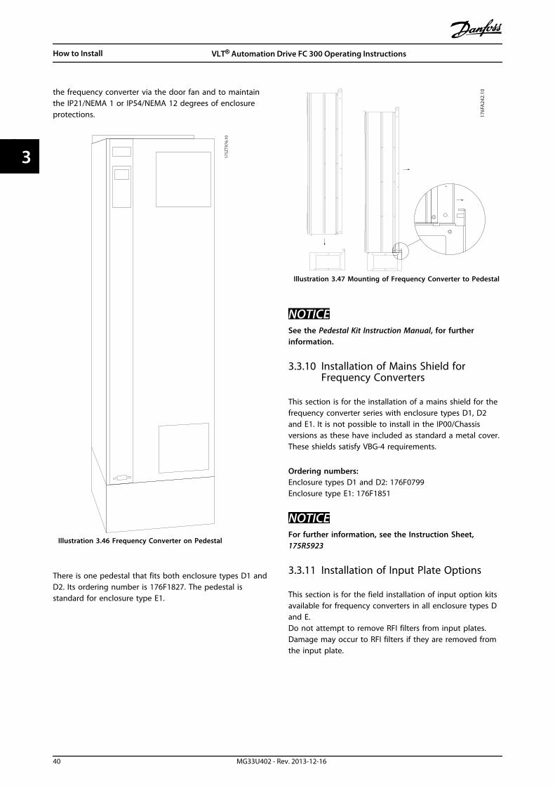
the frequency converter via the door fan and to maintainthe IP21/NEMA 1 or IP54/NEMA 12 degrees of enclosureprotections.
175Z
T976
.10
Illustration 3.46 Frequency Converter on Pedestal
There is one pedestal that fits both enclosure types D1 andD2. Its ordering number is 176F1827. The pedestal isstandard for enclosure type E1.
176FA24
2.10
Illustration 3.47 Mounting of Frequency Converter to Pedestal
NOTICESee the Pedestal Kit Instruction Manual, for furtherinformation.
3.3.10 Installation of Mains Shield forFrequency Converters
This section is for the installation of a mains shield for thefrequency converter series with enclosure types D1, D2and E1. It is not possible to install in the IP00/Chassisversions as these have included as standard a metal cover.These shields satisfy VBG-4 requirements.
Ordering numbers:Enclosure types D1 and D2: 176F0799Enclosure type E1: 176F1851
NOTICEFor further information, see the Instruction Sheet,175R5923
3.3.11 Installation of Input Plate Options
This section is for the field installation of input option kitsavailable for frequency converters in all enclosure types Dand E.Do not attempt to remove RFI filters from input plates.Damage may occur to RFI filters if they are removed fromthe input plate.
How to Install VLT® Automation Drive FC 300 Operating Instructions
40 MG33U402 - Rev. 2013-12-16
33

NOTICEWhere RFI filters are available, there are 2 different type of RFI filters depending on the input plate combination andthe RFI filters interchangeable. Field installable kits in certain cases are the same for all voltages.
380-480 V380-500 V
Fuses Disconnect Fuses RFI RFI Fuses RFI DisconnectFuses
D1 All D1 power sizes 176F8442 176F8450 176F8444 176F8448 176F8446
D2 All D2 power sizes 176F8443 176F8441 176F8445 176F8449 176F8447
E1 FC 102/ FC 202: 315 kWFC 302: 250 kW
176F0253 176F0255 176F0257 176F0258 176F0260
FC 102/ FC 202: 355 -450 kWFC 302: 315 - 400 kW
176F0254 176F0256 176F0257 176F0259 176F0262
Table 3.11 Fuses
525 - 690 V Fuses Disconnect Fuses RFI RFI Fuses RFI DisconnectFuses
D1 FC 102/ FC 202: 45-90kWFC 302: 37-75 kW
175L8829 175L8828 175L8777 NA NA
FC 102/ FC 202:110-160 kWFC 302: 90-132 kW
175L8442 175L8445 175L8777 NA NA
D2 All D2power sizes 175L8827 175L8826 175L8825 NA NA
E1 FC 102/ FC 202:450-500 kWFC 302: 355-400 kW
176F0253 176F0255 NA NA NA
FC 102/ FC 202:560-630 kWFC 302: 500-560 kW
176F0254 176F0258 NA NA NA
Table 3.12
NOTICEFor further information, see the Instruction Installation ofField Installable Kits for VLT Drives
3.3.12 Installation of D or E LoadshareOption
The loadshare option can be installed on frame sizes D1,D2, D3, D4, E1 and E2.
NOTICESee the Loadshare Terminal Kit Instructions, 175R5637 (Dframes) or 177R1114 (E frames), for further information.
Ordering informationFrame size D1/D3: 176F8456Frame size D2/D4: 176F8455Frame size E1/E2: 176F1843
3.4 F Enclosure Panel Options
3.4.1 Enclsoure Type F Options
Space Heaters and ThermostatMounted on the cabinet interior of enclosure type Ffrequency converters, space heaters controlled viaautomatic thermostat help control humidity inside theenclosure, extending the lifetime of frequency convertercomponents in damp environments. The thermostatdefault settings turn on the heaters at 10 °C (50 °F) andturn them off at 15.6 °C (60 °F).
Cabinet Light with Power OutletA light mounted on the cabinet interior of enclosure typeF frequency converters increase visibility during servicingand maintenance. The housing the light includes a poweroutlet for temporarily powering tools or other devices,available in two voltages:
• 230 V, 50 Hz, 2.5 A, CE/ENEC
• 120 V, 60 Hz, 5 A, UL/cUL
How to Install VLT® Automation Drive FC 300 Operating Instructions
MG33U402 - Rev. 2013-12-16 41
3 3
Transformer Tap SetupIf the cabinet light & outlet and/or the space heaters &thermostat are installed Transformer T1 requires it taps tobe set to the proper input voltage. A 380-480/500 Vfrequency converter is set initially to the 525 V tap and a525-690 V frequency converter is set to the 690 V tap toinsure no overvoltage of secondary equipment occurs ifthe tap is not changed before power is applied. SeeTable 3.13 to set the proper tap at terminal T1 located inthe rectifier cabinet. For location in the frequencyconverter, see Illustration 3.48.
Input Voltage Range [V] Tap to Select
380-440 400 V
441-490 460 V
491-550 525 V
551-625 575 V
626-660 660 V
661-690 690 V
Table 3.13
NAMUR TerminalsNAMUR is an international association of automationtechnology users in the process industries, primarilychemical and pharmaceutical industries in Germany.Selection of this option provides terminals organized andlabeled to the specifications of the NAMUR standard forfrequency converter input and output terminals. Thisrequires MCB 112 PTC Thermistor Card and MCB 113Extended Relay Card.
RCD (Residual Current Device)Uses the core balance method to monitor ground faultcurrents in grounded and high-resistance groundedsystems (TN and TT systems in IEC terminology). There is apre-warning (50% of main alarm set-point) and a mainalarm set-point. Associated with each set-point is an SPDTalarm relay for external use. Requires an external “window-type” current transformer (supplied and installed bycustomer).
• Integrated into the frequency converter’s safe-stop circuit
• IEC 60755 Type B device monitors AC, pulsed DC,and pure DC ground fault currents
• LED bar graph indicator of the ground faultcurrent level from 10–100% of the set-point
• Fault memory
• [TEST/RESET]
Insulation Resistance Monitor (IRM)Monitors the insulation resistance in ungrounded systems(IT systems in IEC terminology) between the system phaseconductors and ground. There is an ohmic pre-warningand a main alarm set-point for the insulation level.Associated with each set-point is an SPDT alarm relay forexternal use. Note: only one insulation resistance monitorcan be connected to each ungrounded (IT) system.
• Integrated into the frequency converter’s safe-stop circuit
• LCD display of the ohmic value of the insulationresistance
• Fault Memory
• [INFO], [TEST], and [RESET]
IEC Emergency Stop with Pilz Safety RelayIncludes a redundant 4-wire emergency-stop push-buttonmounted on the front of the enclosure and a Pilz relay thatmonitors it in conjunction with the frequency converter’ssafe-stop circuit and the mains contactor located in theoptions cabinet.
Safe Stop + Pilz RelayProvides a solution for the "Emergency Stop" optionwithout the contactor in F-Enclosure frequency converters.
Manual Motor StartersProvides 3-phase power for electric blowers often requiredfor larger motors. Power for the starters is provided fromthe load side of any supplied contactor, circuit breaker, ordisconnect switch. Power is fused before each motorstarter, and is off when the incoming power to thefrequency converter is off. Up to 2 starters are allowed(one if a 30 A, fuse-protected circuit is ordered). Integratedinto the frequency converter’s safe-stop circuit.Unit features include:
• Operation switch (on/off)
• Short-circuit and overload protection with testfunction
• Manual reset function
30 A, Fuse-Protected Terminals
• 3-phase power matching incoming mains voltagefor powering auxiliary customer equipment
• Not available if 2 manual motor starters areselected
• Terminals are off when the incoming power tothe frequency converter is off
• Power for the fused protected terminals will beprovided from the load side of any suppliedcontactor, circuit breaker, or disconnect switch.
24 V DC Power Supply
• 5 A, 120 W, 24 V DC
• Protected against output over-current, overload,short circuits, and over-temperature
• For powering customer-supplied accessorydevices such as sensors, PLC I/O, contactors,temperature probes, indicator lights, and/or otherelectronic hardware
• Diagnostics include a dry DC-ok contact, a greenDC-ok LED, and a red overload LED
How to Install VLT® Automation Drive FC 300 Operating Instructions
42 MG33U402 - Rev. 2013-12-16
33

External Temperature MonitoringDesigned for monitoring temperatures of external systemcomponents, such as the motor windings and/or bearings.Includes five universal input modules. The modules areintegrated into the frequency converter’s safe-stop circuitand can be monitored via a fieldbus network (requires thepurchase of a separate module/bus coupler).
Universal inputs (5)Signal types:
• RTD inputs (including PT100), 3-wire or 4-wire
• Thermocouple
• Analog current or analog voltage
Additional features:
• One universal output, configurable for analogvoltage or analog current
• Two output relays (N.O.)
• Dual-line LC display and LED diagnostics
• Sensor lead wire break, short-circuit, and incorrectpolarity detection
• Interface setup software
3.5 Electrical Installation
3.5.1 Power Connections
Cabling and Fusing
NOTICECables GeneralAll cabling must comply with national and localregulations on cable cross-sections and ambienttemperature. UL applications require 75 °C copperconductors. 75 and 90 °C copper conductors arethermally acceptable for the frequency converter to usein non UL applications.
The power cable connections are situated as shown below.Dimensioning of cable cross section must be done inaccordance with the current ratings and local legislation.See the Specifications section for details.
For protection of the frequency converter, therecommended fuses must be used or the unit must bewith built-in fuses. Recommended fuses can be seen in thetables of the fuse section. Always ensure that proper fusingis made according to local regulation.
The mains connection is fitted to the mains switch if this isincluded.
3 Phase
power
input
130B
A02
6.10
91 (L1)
92 (L2)
93 (L3)
95 PE
Illustration 3.48 Power Cable Connections
NOTICEThe motor cable must be screened/armoured. If anunscreened/unarmoured cable is used, some EMCrequirements are not complied with. Use a screened/armoured motor cable to comply with EMC emissionspecifications. For more information, see EMC specifi-cations in the Design Guide.
See section General Specifications for correct dimensioningof motor cable cross-section and length.
Screening of cablesAvoid installation with twisted screen ends (pigtails). Theyspoil the screening effect at higher frequencies. If it isnecessary to break the screen to install a motor isolator ormotor contactor, the screen must be continued at thelowest possible HF impedance.
Connect the motor cable screen to both the de-couplingplate of the frequency converter and to the metal housingof the motor.
Make the screen connections with the largest possiblesurface area (cable clamp). This is done by using thesupplied installation devices within the frequencyconverter.
Cable-length and cross-sectionThe frequency converter has been EMC tested with a givenlength of cable. Keep the motor cable as short as possibleto reduce the noise level and leakage currents.
Switching frequencyWhen frequency converters are used together with Sine-wave filters to reduce the acoustic noise from a motor, theswitching frequency must be set according to theinstruction in 14-01 Switching Frequency.
How to Install VLT® Automation Drive FC 300 Operating Instructions
MG33U402 - Rev. 2013-12-16 43
3 3

Term.no.
96 97 98 99
U V W PE1
)
Motor voltage 0-100% of mainsvoltage.3 wires out of motor
U1 V1 W1PE1
)
Delta-connected
W2
U2 V2 6 wires out of motor
U1 V1 W1 PE1
)
Star-connected U2, V2, W2U2, V2 and W2 to be intercon-nected separately.
Table 3.14
1)Protected Earth Connection
NOTICEIn motors without phase insulation paper or otherinsulation reinforcement suitable for operation withvoltage supply (such as a frequency converter), fit a Sine-wave filter on the output of the frequency converter.
U1
V1
W1
175Z
A11
4.11
96 97 98 96 97 98
FC FC
Motor MotorU
2V2
W2
U1
V1
W1
U2
V2
W2
Illustration 3.49 Star/Delta Connections
How to Install VLT® Automation Drive FC 300 Operating Instructions
44 MG33U402 - Rev. 2013-12-16
33

DOWN
DOWN
DOWN
DOWN
R/L1 91
S/L2 92FASTENER TORQUE: M10 19 NM (14 FT-LB
T/L3 93
FASTENER TORQUE: M8 9.6 NM (7 FT-LB)
FASTENER TORQUE: M8 9.6 NM (7 FT-LB)
FASTENER TORQUE: M1019 NM (14 FT-LB)
-DC 88
+DC 89
-R 81
+R 82
U/T1 96
V/T2 97
W/T3 98
130B
B015
.10
1
2
3
4
6
7
8
9
10
5
Illustration 3.50 Compact IP21 (NEMA 1) and IP54 (NEMA 12),Enclosure Type D1
130B
B016
.10
R/L1 91S/L2 92
T/L3 93
FASTENERTORQUE.
M10 19 NM (14 FT-LB)
1
2
3
4
5
6
7
8
9
10
FASTENER TORQUE:
FASTENER TORQUE: M10 19 NM (7 FT-LB)
FASTENER TORQUE:
-DV 88
-R 81+R 82
U/T1 96V/T2 97
W/T3 98+DC 89M8 9.6 NM (7 FT-LB)
M8 9.6 NM (7 FT-LB)
Illustration 3.51 Compact IP21 (NEMA 1) and IP54 (NEMA 12)with Disconnect, Fuse and RFI Filter, Enclosure Type D2
1) AUX Relay 5) Brake
01 02 03 -R +R
04 05 06 81 82
2) Temp Switch 6) SMPS Fuse (see fuse tables for part number)
106 104 105 7) AUX Fan
3) Mains 100 101 102 103
R S T L1 L2 L1 L2
91 92 93 8) Fan Fuse (see fuse tables for part number)
L1 L2 L3 9) Mains ground
4) Load sharing 10) Motor
-DC +DC U V W
88 89 96 97 98
T1 T2 T3
Table 3.15 Legend to Illustration 3.50 and Illustration 3.51
How to Install VLT® Automation Drive FC 300 Operating Instructions
MG33U402 - Rev. 2013-12-16 45
3 3

130B
B017
.10
1
2
3
4
5
6
7
8
9
10
Illustration 3.52 Compact IP00 (Chassis), Enclosure Type D3
1
2
3
4
5
6
7
8
9
1013
0BB0
18.1
0
FASTEMER TORQUE: M10 19 NM (14 FT-LB)
FASTEMER TORQUE: M8 9.6 NM (7 FT-LB)
R/L1 91
-DC 88
+DC 89
FASTEMER TORQUE: M8 9.6 NM (7 FT-LB)
FASTEMER TORQUE: M10 19 NM (14 FT-LB)
R 81
+DR 82
U/T1 96
V/T2 97
W/T3 98
S/L2 92T/L3 93
Illustration 3.53 Compact IP00 (Chassis) with Disconnect, Fuseand RFI Filter, Enclosure Type D4
1) AUX Relay 4) Load sharing 8) Fan Fuse (see fuse tables forpart number)
01 02 03 -DC +DC 9) Mains ground
04 05 06 88 89 10) Motor
2) Temp Switch 5) Brake U V W
106 104 105 -R +R 96 97 98
3) Mains 81 82 T1 T2 T3
R S T 6) SMPS Fuse (see fuse tables for part number)
91 92 93 7) AUX Fan
L1 L2 L3 100 101 102 103
L1 L2 L1 L2
Table 3.16 Legend to Illustration 3.52 and Illustration 3.53
How to Install VLT® Automation Drive FC 300 Operating Instructions
46 MG33U402 - Rev. 2013-12-16
33
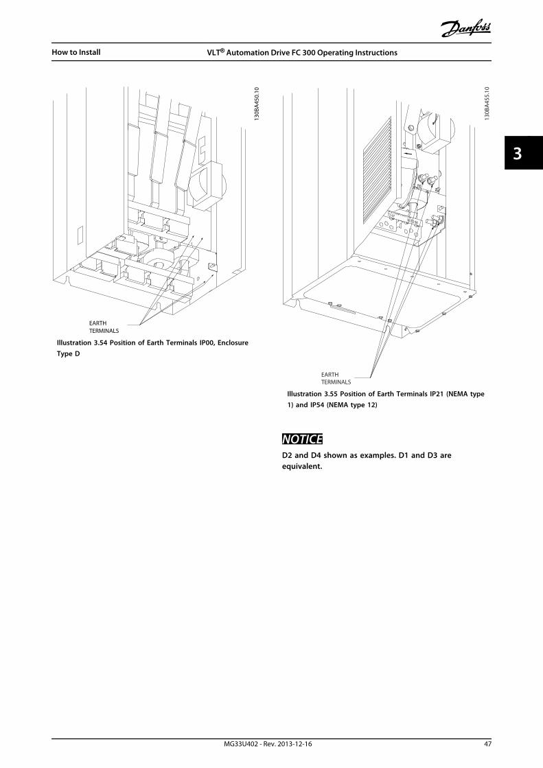
TERMINALSEARTH
130B
A45
0.10
Illustration 3.54 Position of Earth Terminals IP00, EnclosureType D
130B
A45
5.10
M10 19 NM (14 FT -LB)T2 97
W/T3 98
EARTHTERMINALS
Illustration 3.55 Position of Earth Terminals IP21 (NEMA type1) and IP54 (NEMA type 12)
NOTICED2 and D4 shown as examples. D1 and D3 areequivalent.
How to Install VLT® Automation Drive FC 300 Operating Instructions
MG33U402 - Rev. 2013-12-16 47
3 3

130B
B019
.10
1
2
3
4
5
6
7
8
9
10
Illustration 3.56 Compact IP21 (NEMA 1) and IP54 (NEMA 12)Enclosure Type E1
130B
B020
.10
1
2
3
4
5
6
7
8
10
Illustration 3.57 Compact IP00 (Chassis) with Disconnect, Fuseand RFI Filter, Enclosure Type E2
1) AUX Relay 5) Load sharing
01 02 03 -DC +DC
04 05 06 88 89
2) Temp Switch 6) SMPS Fuse (see fuse tables for part number)
106 104 105 7) Fan Fuse (see fuse tables for part number)
3) Mains 8) AUX Fan
R S T 100 101 102 103
91 92 93 L1 L2 L1 L2
L1 L2 L3 9) Mains ground
4) Brake 10) Motor
-R +R U V W
81 82 96 97 98
T1 T2 T3
Table 3.17 Legend to Illustration 3.56 and Illustration 3.57
How to Install VLT® Automation Drive FC 300 Operating Instructions
48 MG33U402 - Rev. 2013-12-16
33
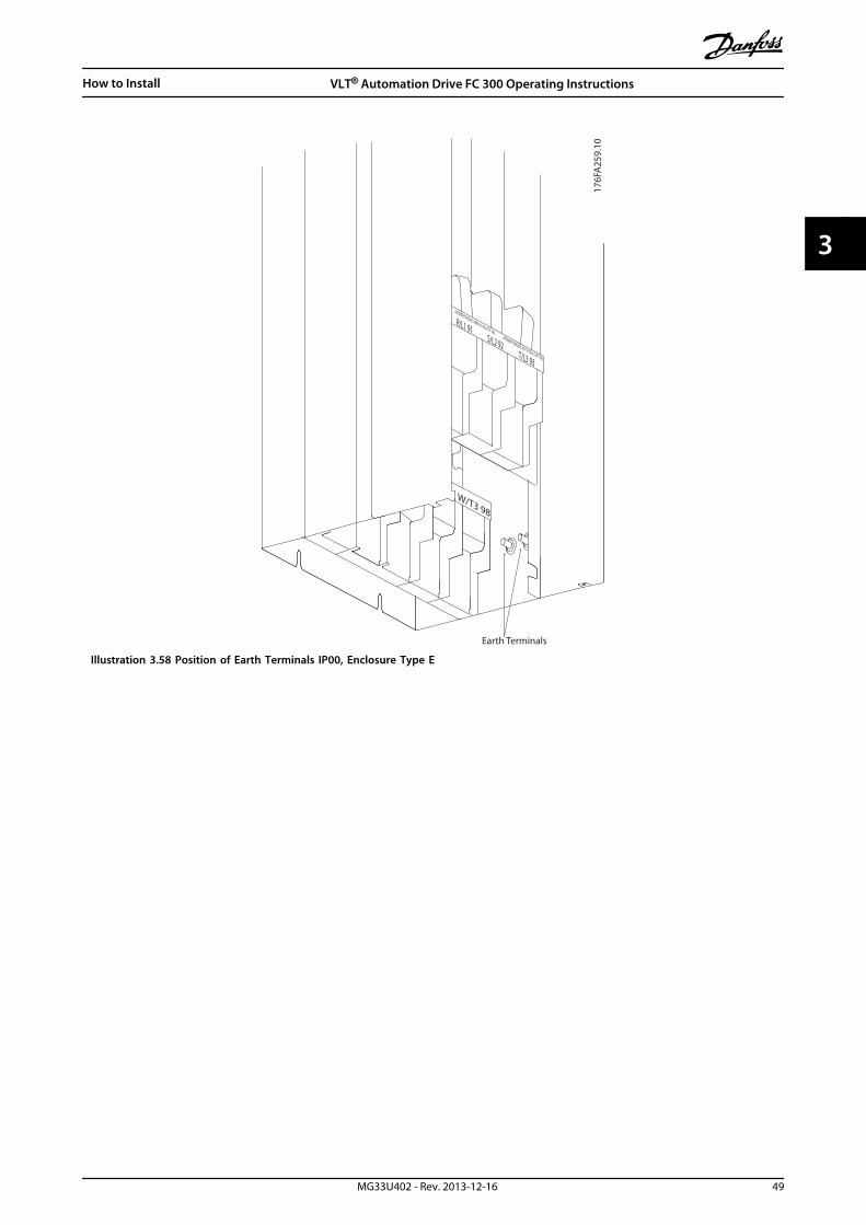
176F
A25
9.10
Earth Terminals
:ASTENER TORQUE: MM8 9.6 Nm (7FT-LB)ASTENER TORQUE: M10 19 Nm (14FT-LB)
S/L2 92T/L3 93
R/L1 91
W/T3 98
Illustration 3.58 Position of Earth Terminals IP00, Enclosure Type E
How to Install VLT® Automation Drive FC 300 Operating Instructions
MG33U402 - Rev. 2013-12-16 49
3 3

+DC 89FASTENER TORQUE: M10 19Nm (14 FT -LB)
+DC 89
130B
A86
0.10
1
5
4
3
2
8
10
9
FUSE
C J3ONNECT
CH22 CH22 CH22CTI25MB
FASTENER TORQUE: M10 19Nm (14 FT -LB)
CTI25MBCH22 CH22 CH22
7
6
1) 24 V DC, 5 A 5) Loadsharing
T1 Output Taps -DC +DC
Temp Switch 88 89
106 104 105 6) Control Transformer Fuses (2 or 4 pieces). See fuse tables for part numbers
2) Manual Motor Starters 7) SMPS Fuse. See fuse tables for part numbers
3) 30 A Fuse Protected Power Terminals 8) Manual Motor Controller fuses (3 or 6 pieces). See fuse tables for part numbers
4) Mains 9) Line Fuses, enclosure types F1 and F2 (3 pieces). See fuse tables for partnumbers
R S T 10) 30 Amp Fuse Protected Power fuses
L1 L2 L3
Illustration 3.59 Rectifier Cabinet, Enclosure Types F1, F2, F3 and F4
How to Install VLT® Automation Drive FC 300 Operating Instructions
50 MG33U402 - Rev. 2013-12-16
33

2
5
6
4, 8, 9
130B
A86
1.111
1) External Temperature Monitoring 6) Motor
2) AUX Relay U V W
01 02 03 96 97 98
04 05 06 T1 T2 T3
3) NAMUR 7) NAMUR Fuse. See fuse tables for part numbers
4) AUX Fan 8) Fan Fuses. See fuse tables for part numbers
100 101 102 103 9) SMPS Fuses. See fuse tables for part numbers
L1 L2 L1 L2
5) Brake
-R +R
81 82
Illustration 3.60 Inverter Cabinet, Enclosure Types F1 and F3
How to Install VLT® Automation Drive FC 300 Operating Instructions
MG33U402 - Rev. 2013-12-16 51
3 3

3
5
U/T1 96FASTENER TORQUE: M10 19 Nm (14 FT-LB)
V/T2 97 W/T3 98 U/T1 96FASTENER TORQUE: M10 19 Nm (14 FT-LB)
V/T2 97 W/T3 98 U/T1 96FASTENER TORQUE: M10 19 Nm (14 FT-LB)
V/T2 97 W/T3 98
6
4, 8, 9
21
7
130B
A86
2.12
1) External Temperature Monitoring 6) Motor
2) AUX Relay U V W
01 02 03 96 97 98
04 05 06 T1 T2 T3
3) NAMUR 7) NAMUR Fuse. See fuse tables for part numbers
4) AUX Fan 8) Fan Fuses. See fuse tables for part numbers
100 101 102 103 9) SMPS Fuses. See fuse tables for part numbers
L1 L2 L1 L2
5) Brake
-R +R
81 82
Illustration 3.61 Inverter Cabinet, Enclosure Types F2 and F4
How to Install VLT® Automation Drive FC 300 Operating Instructions
52 MG33U402 - Rev. 2013-12-16
33
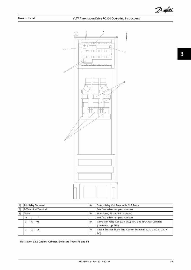
2
3
4
5
6
7
1
130B
A85
3.12
1) Pilz Relay Terminal 4) Safety Relay Coil Fuse with PILZ Relay
2) RCD or IRM Terminal See fuse tables for part numbers
3) Mains 5) Line Fuses, F3 and F4 (3 pieces)
R S T See fuse tables for part numbers
91 92 93 6) Contactor Relay Coil (230 VAC). N/C and N/O Aux Contacts(customer supplied)
L1 L2 L3 7) Circuit Breaker Shunt Trip Control Terminals (230 V AC or 230 VDC)
Illustration 3.62 Options Cabinet, Enclosure Types F3 and F4
How to Install VLT® Automation Drive FC 300 Operating Instructions
MG33U402 - Rev. 2013-12-16 53
3 3

3.5.2 Grounding
The following basic issues need to be considered wheninstalling a frequency converter, so as to obtain electro-magnetic compatibility (EMC).
• Safety grounding: The frequency converter has ahigh leakage current and must be groundedappropriately for safety reasons. Apply localsafety regulations.
• High-frequency grounding: Keep the ground wireconnections as short as possible.
Connect the different ground systems at the lowestpossible conductor impedance. The lowest possibleconductor impedance is obtained by keeping theconductor as short as possible and by using the greatestpossible surface area.The metal cabinets of the different devices are mountedon the cabinet rear plate using the lowest possible HFimpedance. This avoids having different HF voltages forthe individual devices and avoids the risk of radiointerference currents running in connection cables thatmay be used between the devices. The radio interferencehas been reduced.To obtain a low HF impedance, use the fastening bolts ofthe devices as HF connection to the rear plate. It isnecessary to remove insulating paint or similar from thefastening points.
3.5.3 Extra Protection (RCD)
ELCB relays, multiple protective earthing or earthing canbe used as extra protection, provided that local safetyregulations are complied with.
In case of an ground fault, a DC component may developin the fault current.
If ELCB relays are used, local regulations must be observed.Relays must be suitable for protection of 3-phaseequipment with a bridge rectifier and for a brief dischargeon power-up.
See also Special Conditions in the Design Guide.
3.5.4 RFI Switch
Mains supply isolated from earthIf the frequency converter is supplied from an isolatedmains source ( IT mains, floating delta and grounded delta)or TT/TN-S mains with grounded leg, the RFI switch isrecommended to be turned off (OFF) via 14-50 RFI Filter onthe frequency converter and 14-50 RFI Filter on the filter.For further reference, see IEC 364-3. In case optimum EMCperformance is needed, parallel motors are connected orthe motor cable length is above 25 m, it is recommendedto set 14-50 RFI Filter to [ON].
In OFF, the internal RFI capacities (filter capacitors)between the chassis and the intermediate circuit are cutoff to avoid damage to the intermediate circuit and toreduce the earth capacity currents (according to IEC61800-3).Also refer to the application note VLT on IT Mains It isimportant to use isolation monitors that are capable foruse together with power electronics (IEC 61557-8).
3.5.5 Torque
When tightening all electrical connections it is veryimportant to tighten with the correct torque. Too low ortoo high torque results in a bad electrical connection. Usea torque wrench to ensure correct torque.
176F
A24
7.12
Nm/in-lbs
-DC 88+DC 89
R/L1 91S/L2 92
T/L3 93
U/T1 96V/T2 97
W/T3
Illustration 3.63 Tightening Bolts with a Torque Wrench
Enclosuretypes
Terminal Torque [Nm] (in-lbs) Bolt size
D MainsMotor
19-40(168-354)
M10
Load sharingBrake
8.5-20.5(75-181)
M8
E MainsMotorLoad sharing
19-40(168-354)
M10
Brake 8.5-20.5(75-181)
M8
How to Install VLT® Automation Drive FC 300 Operating Instructions
54 MG33U402 - Rev. 2013-12-16
33

Enclosuretypes
Terminal Torque [Nm] (in-lbs) Bolt size
F MainsMotor
19-40(168-354)
M10
Load sharingBrakeRegen
19-40(168-354)8.5-20.5(75-181)8.5-20.5(75-181)
M10M8M8
Table 3.18 Torque for Terminals
3.5.6 Shielded Cables
WARNINGDanfoss recommends to use shielded cables between theLCL filter and the AFE unit. Unshielded cables can bebetween transformer and LCL filter input side.
It is important that shielded and armoured cables areconnected in a proper way to ensure the high EMCimmunity and low emissions.
The connection can be made using either cable glandsor clamps
• EMC cable glands: Generally available cableglands can be used to ensure an optimum EMCconnection.
• EMC cable clamp: Clamps allowing easyconnection are supplied with the frequencyconverter.
3.5.7 Motor Cable
The motor must be connected to terminals U/T1/96, V/T2/97, W/T3/98. Earth to terminal 99. All types of 3-phaseasynchronous standard motors can be used with afrequency converter unit. The factory setting is forclockwise rotation with the frequency converter outputconnected as follows:
Terminal No. Function
96, 97, 98, 99 Mains U/T1, V/T2, W/T3Earth
Table 3.19 Mains Terminals
• Terminal U/T1/96 connectedto U-phase
• Terminal V/T2/97 connectedto V-phase
• Terminal W/T3/98connected to W-phase
175H
A03
6.11
U1 V1 W1
96 97 98
FC
MotorU2 V2 W2
U1 V1 W1
96 97 98
FC
MotorU2 V2 W2
Table 3.20
The direction of rotation can be changed by switching 2 phases inthe motor cable or by changing the setting of 4-10 Motor SpeedDirection.
Motor rotation check can be performed using 1-28 MotorRotation Check and following the steps shown in thedisplay.
F enclosure requirementsF1/F3 requirements: Motor phase cable quantities must bemultiples of 2, resulting in 2, 4, 6, or 8 (1 cable is notallowed) to obtain equal amount of wires attached to bothinverter module terminals. The cables are required to beequal length within 10% between the inverter moduleterminals and the first common point of a phase. Therecommended common point is the motor terminals.
F2/F4 requirements: Motor phase cable quantities must bemultiples of 3, resulting in 3, 6, 9, or 12 (1 or 2 cables arenot allowed) to obtain equal amount of wires attached toeach inverter module terminal. The wires are required tobe equal length within 10% between the inverter moduleterminals and the first common point of a phase. Therecommended common point is the motor terminals.
Output junction box requirements: The length, minimum2.5 m, and quantity of cables must be equal from eachinverter module to the common terminal in the junctionbox.
NOTICEIf a retrofit application requires unequal amount of wiresper phase, consult the factory for requirements anddocumentation or use the top/bottom entry side cabinetoption.
How to Install VLT® Automation Drive FC 300 Operating Instructions
MG33U402 - Rev. 2013-12-16 55
3 3
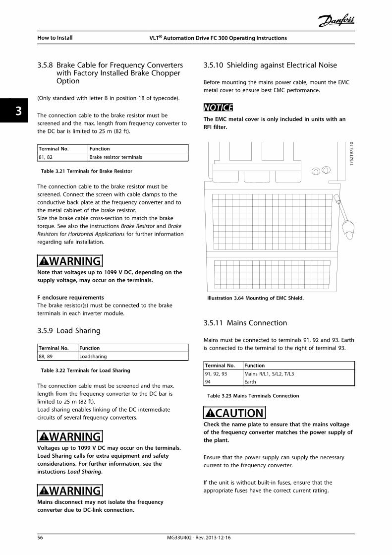
3.5.8 Brake Cable for Frequency Converterswith Factory Installed Brake ChopperOption
(Only standard with letter B in position 18 of typecode).
The connection cable to the brake resistor must bescreened and the max. length from frequency converter tothe DC bar is limited to 25 m (82 ft).
Terminal No. Function
81, 82 Brake resistor terminals
Table 3.21 Terminals for Brake Resistor
The connection cable to the brake resistor must bescreened. Connect the screen with cable clamps to theconductive back plate at the frequency converter and tothe metal cabinet of the brake resistor.Size the brake cable cross-section to match the braketorque. See also the instructions Brake Resistor and BrakeResistors for Horizontal Applications for further informationregarding safe installation.
WARNINGNote that voltages up to 1099 V DC, depending on thesupply voltage, may occur on the terminals.
F enclosure requirementsThe brake resistor(s) must be connected to the braketerminals in each inverter module.
3.5.9 Load Sharing
Terminal No. Function
88, 89 Loadsharing
Table 3.22 Terminals for Load Sharing
The connection cable must be screened and the max.length from the frequency converter to the DC bar islimited to 25 m (82 ft).Load sharing enables linking of the DC intermediatecircuits of several frequency converters.
WARNINGVoltages up to 1099 V DC may occur on the terminals.Load Sharing calls for extra equipment and safetyconsiderations. For further information, see theinstuctions Load Sharing.
WARNINGMains disconnect may not isolate the frequencyconverter due to DC-link connection.
3.5.10 Shielding against Electrical Noise
Before mounting the mains power cable, mount the EMCmetal cover to ensure best EMC performance.
NOTICEThe EMC metal cover is only included in units with anRFI filter.
175Z
T975
.10
Illustration 3.64 Mounting of EMC Shield.
3.5.11 Mains Connection
Mains must be connected to terminals 91, 92 and 93. Earthis connected to the terminal to the right of terminal 93.
Terminal No. Function
91, 92, 9394
Mains R/L1, S/L2, T/L3Earth
Table 3.23 Mains Terminals Connection
CAUTIONCheck the name plate to ensure that the mains voltageof the frequency converter matches the power supply ofthe plant.
Ensure that the power supply can supply the necessarycurrent to the frequency converter.
If the unit is without built-in fuses, ensure that theappropriate fuses have the correct current rating.
How to Install VLT® Automation Drive FC 300 Operating Instructions
56 MG33U402 - Rev. 2013-12-16
33
3.5.12 External Fan Supply
In case the frequency converter is supplied by DC or if thefan must run independently of the power supply, anexternal power supply can be applied. The connection ismade on the power card.
Terminal No. Function
100, 101102, 103
Auxiliary supply S, TInternal supply S, T
Table 3.24 External Fan Supply Terminals
The connector located on the power card provides theconnection of line voltage for the cooling fans. The fansare connected from factory to be supplied from a commonAC line (jumpers between 100-102 and 101-103). If externalsupply is needed, the jumpers are removed and the supplyis connected to terminals 100 and 101. Use a 5 A fuse forprotection. In UL applications, use a LittelFuse KLK-5 orequivalent.
3.5.13 Fuses
It is recommended to use fuses and/or circuit breakers onthe supply side as protection in case of component break-down inside the frequency converter (first fault).
NOTICEThis is mandatory to ensure compliance with IEC 60364for CE or NEC 2009 for UL.
WARNINGPersonnel and property must be protected against theconsequence of component break-down internally in thefrequency converter.
Branch circuit protectionTo protect the installation against electrical and fire hazard,all branch circuits in an installation, switch gear, machinesetc., must be protected against short-circuit andovercurrent according to national/international regulations.
NOTICEThe recommendations given do not cover branch circuitprotection for UL.
Short-circuit protection:Danfoss recommends using the fuses/circuit breakersmentioned below to protect service personnel andproperty in case of component break-down in thefrequency converter.
Non UL complianceIf UL/cUL is not to be complied with, Danfoss recommendsusing the following fuses, which ensure compliance withEN50178:In case of malfunction, not following the recommendationmay result in unnecessary damage to the frequencyconverter.
P90 - P200 380 - 500 V type gG
P250 - P400 380 - 500 V type gR
Table 3.25 Recommended EN 50178 Fuses
How to Install VLT® Automation Drive FC 300 Operating Instructions
MG33U402 - Rev. 2013-12-16 57
3 3
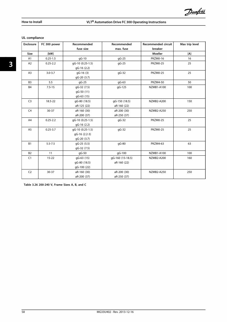
UL compliance
Enclosure FC 300 power Recommendedfuse size
Recommendedmax. fuse
Recommended circuitbreaker
Max trip level
Size [kW] Moeller [A]
A1 0.25-1.5 gG-10 gG-25 PKZM0-16 16
A2 0.25-2.2 gG-10 (0.25-1.5)gG-16 (2.2)
gG-25 PKZM0-25 25
A3 3.0-3.7 gG-16 (3)gG-20 (3.7)
gG-32 PKZM0-25 25
B3 5.5 gG-25 gG-63 PKZM4-50 50
B4 7.5-15 gG-32 (7.5)gG-50 (11)gG-63 (15)
gG-125 NZMB1-A100 100
C3 18.5-22 gG-80 (18.5)aR-125 (22)
gG-150 (18.5)aR-160 (22)
NZMB2-A200 150
C4 30-37 aR-160 (30)aR-200 (37)
aR-200 (30)aR-250 (37)
NZMB2-A250 250
A4 0.25-2.2 gG-10 (0.25-1.5)gG-16 (2.2)
gG-32 PKZM0-25 25
A5 0.25-3.7 gG-10 (0.25-1.5)gG-16 (2.2-3)gG-20 (3.7)
gG-32 PKZM0-25 25
B1 5.5-7.5 gG-25 (5.5)gG-32 (7.5)
gG-80 PKZM4-63 63
B2 11 gG-50 gG-100 NZMB1-A100 100
C1 15-22 gG-63 (15)gG-80 (18.5)gG-100 (22)
gG-160 (15-18.5)aR-160 (22)
NZMB2-A200 160
C2 30-37 aR-160 (30)aR-200 (37)
aR-200 (30)aR-250 (37)
NZMB2-A250 250
Table 3.26 200-240 V, Frame Sizes A, B, and C
How to Install VLT® Automation Drive FC 300 Operating Instructions
58 MG33U402 - Rev. 2013-12-16
33

Enclosure FC 300 power Recommendedfuse size
RecommendedMax. fuse
Recommended circuitbreaker
Max trip level
Size [kW] Moeller [A]
A1 0.37-1.5 gG-10 gG-25 PKZM0-16 16
A2 0.37-4.0 gG-10 (0.37-3)gG-16 (4)
gG-25 PKZM0-25 25
A3 5.5-7.5 gG-16 gG-32 PKZM0-25 25
B3 11-15 gG-40 gG-63 PKZM4-50 50
B4 18.5-30 gG-50 (18.5)gG-63 (22)gG-80 (30)
gG-125 NZMB1-A100 100
C3 37-45 gG-100 (37)gG-160 (45)
gG-150 (37)gG-160 (45)
NZMB2-A200 150
C4 55-75 aR-200 (55)aR-250 (75)
aR-250 NZMB2-A250 250
A4 0.37-4 gG-10 (0.37-3)gG-16 (4)
gG-32 PKZM0-25 25
A5 0.37-7.5 gG-10 (0.37-3)gG-16 (4-7.5)
gG-32 PKZM0-25 25
B1 11-15 gG-40 gG-80 PKZM4-63 63
B2 18.5-22 gG-50 (18.5)gG-63 (22)
gG-100 NZMB1-A100 100
C1 30-45 gG-80 (30)gG-100 (37)gG-160 (45)
gG-160 NZMB2-A200 160
C2 55-75 aR-200 (55)aR-250 (75)
aR-250 NZMB2-A250 250
D 90-200
gG-300 (90)gG-350 (110)gG-400 (132)gG-500 (160)gG-630 (200)
gG-300 (90)gG-350 (110)gG-400 (132)gG-500 (160)gG-630 (200)
- -
E 250-400aR-700 (250)
aR-900 (315-400)aR-700 (250)
aR-900 (315-400)- -
F 450-800aR-1600 (450-500)aR-2000 (560-630)aR-2500 (710-800)
aR-1600 (450-500)aR-2000 (560-630)aR-2500 (710-800)
- -
Table 3.27 380-500 V, Frame Sizes A, B, C, D, E, and F
How to Install VLT® Automation Drive FC 300 Operating Instructions
MG33U402 - Rev. 2013-12-16 59
3 3

Enclosure FC 300 power Recommendedfuse size
RecommendedMax. fuse
Recommended circuitbreaker
Max trip level
Size [kW] Moeller [A]
A2 0-75-4.0 gG-10 gG-25 PKZM0-25 25
A3 5.5-7.5 gG-10 (5.5)gG-16 (7.5)
gG-32 PKZM0-25 25
B3 11-15 gG-25 (11)gG-32 (15)
gG-63 PKZM4-50 50
B4 18.5-30 gG-40 (18.5)gG-50 (22)gG-63 (30)
gG-125 NZMB1-A100 100
C3 37-45 gG-63 (37)gG-100 (45)
gG-150 NZMB2-A200 150
C4 55-75 aR-160 (55)aR-200 (75)
aR-250 NZMB2-A250 250
A5 0.75-7.5 gG-10 (0.75-5.5)gG-16 (7.5)
gG-32 PKZM0-25 25
B1 11-18 gG-25 (11)gG-32 (15)
gG-40 (18.5)
gG-80 PKZM4-63 63
B2 22-30 gG-50 (22)gG-63 (30)
gG-100 NZMB1-A100 100
C1 37-55 gG-63 (37)gG-100 (45)aR-160 (55)
gG-160 (37-45)aR-250 (55)
NZMB2-A200 160
C2 75 aR-200 (75) aR-250 NZMB2-A250 250
Table 3.28 525-600 V, Frame Sizes A, B, and C
How to Install VLT® Automation Drive FC 300 Operating Instructions
60 MG33U402 - Rev. 2013-12-16
33

Enclosure Power [kW] Recommendedfuse size
RecommendedMax. fuse
Recommended circuitbreakerMoeller
Max trip level [A]
A3 1.1-7.5 gG-6 (3)gG-10 (2)gG-16 (2)
gG-25
B2 22-30 gG-25 (11)gG-32 (15)gG-32 (18)gG-40 (22)
gG-63 - -
C2 75-90 gG-63 (30)gG-63 (37)gG-80 (45)
gG-100 (55)gG-125 (75)
gG-80 (30)gG-100 (37)gG-125 (45)
gG-160 (55-75)
- -
C3 44-55gG-80
gG-100gG-100gG-125
D -
gG-125 (37)gG-160 (45)
gG-200 (55-75)aR-250 (90)
aR-315 (110)aR-350 (132-160)
aR-400 (200)aR-500 (250)aR-550 (315)
gG-125 (37)gG-160 (45)
gG-200 (55-75)aR-250 (90)
aR-315 (110)aR-350 (132-160)
aR-400 (200)aR-500 (250)aR-550 (315)
- -
E -aR-700 (355-400)aR-900 (500-560)
aR-700 (355-400)aR-900 (500-560)
- -
F -aR-1600 (630-900)
aR-2000 (1000)aR-2500 (1200)
aR-1600 (630-900)aR-2000 (1000)aR-2500 (1200)
- -
Table 3.29 525-690 V, Frame Sizes A, B, C, D, E and F
How to Install VLT® Automation Drive FC 300 Operating Instructions
MG33U402 - Rev. 2013-12-16 61
3 3

UL ComplianceFuses or circuit breakers are mandatory to comply with NEC 2009. Danfoss recommends using a selection of the following.
The fuses below are suitable for use on a circuit capable of delivering 100,000 Arms (symmetrical), 240 V, or 480 V, or 500 V,or 600 V depending on the frequency converter voltage rating. With the proper fusing the drive Short Circuit Current Rating(SCCR) is 100,000 Arms.
Recommended max. fuse
FC 300Power
Bussmann Bussmann Bussmann Bussmann Bussmann Bussmann
[kW] Type RK1 1) Type J Type T Type CC Type CC Type CC
0.25-0.37 KTN-R-05 JKS-05 JJN-05 FNQ-R-5 KTK-R-5 LP-CC-5
0.55-1.1 KTN-R-10 JKS-10 JJN-10 FNQ-R-10 KTK-R-10 LP-CC-10
1.5 KTN-R-15 JKS-15 JJN-15 FNQ-R-15 KTK-R-15 LP-CC-15
2.2 KTN-R-20 JKS-20 JJN-20 FNQ-R-20 KTK-R-20 LP-CC-20
3.0 KTN-R-25 JKS-25 JJN-25 FNQ-R-25 KTK-R-25 LP-CC-25
3.7 KTN-R-30 JKS-30 JJN-30 FNQ-R-30 KTK-R-30 LP-CC-30
5.5 KTN-R-50 KS-50 JJN-50 - - -
7.5 KTN-R-60 JKS-60 JJN-60 - - -
11 KTN-R-80 JKS-80 JJN-80 - - -
15-18.5 KTN-R-125 JKS-125 JJN-125 - - -
22 KTN-R-150 JKS-150 JJN-150 - - -
30 KTN-R-200 JKS-200 JJN-200 - - -
37 KTN-R-250 JKS-250 JJN-250 - - -
Table 3.30 200-240 V, Frame Sizes A, B, and C
Recommended max. fuse
FC 300Power
SIBA Littel fuseFerraz-
ShawmutFerraz-
Shawmut
[kW] Type RK1 Type RK1 Type CC Type RK13)
0.25-0.37 5017906-005 KLN-R-05 ATM-R-05 A2K-05-R
0.55-1.1 5017906-010 KLN-R-10 ATM-R-10 A2K-10-R
1.5 5017906-016 KLN-R-15 ATM-R-15 A2K-15-R
2.2 5017906-020 KLN-R-20 ATM-R-20 A2K-20-R
3.0 5017906-025 KLN-R-25 ATM-R-25 A2K-25-R
3.7 5012406-032 KLN-R-30 ATM-R-30 A2K-30-R
5.5 5014006-050 KLN-R-50 - A2K-50-R
7.5 5014006-063 KLN-R-60 - A2K-60-R
11 5014006-080 KLN-R-80 - A2K-80-R
15-18.5 2028220-125 KLN-R-125 - A2K-125-R
22 2028220-150 KLN-R-150 - A2K-150-R
30 2028220-200 KLN-R-200 - A2K-200-R
37 2028220-250 KLN-R-250 - A2K-250-R
Table 3.31 200-240 V, Frame Sizes A, B, and C
How to Install VLT® Automation Drive FC 300 Operating Instructions
62 MG33U402 - Rev. 2013-12-16
33

Recommended max. fuse
FC 300Power
Bussmann Littel fuseFerraz-
ShawmutFerraz-
Shawmut
[kW] Type JFHR22) JFHR2 JFHR24) J
0.25-0.37 FWX-5 - - HSJ-6
0.55-1.1 FWX-10 - - HSJ-10
1.5 FWX-15 - - HSJ-15
2.2 FWX-20 - - HSJ-20
3.0 FWX-25 - - HSJ-25
3.7 FWX-30 - - HSJ-30
5.5 FWX-50 - - HSJ-50
7.5 FWX-60 - - HSJ-60
11 FWX-80 - - HSJ-80
15-18.5 FWX-125 - - HSJ-125
22 FWX-150 L25S-150 A25X-150 HSJ-150
30 FWX-200 L25S-200 A25X-200 HSJ-200
37 FWX-250 L25S-250 A25X-250 HSJ-250
Table 3.32 200-240 V, Frame Sizes A, B, and C
1) KTS-fuses from Bussmann may substitute KTN for 240 V frequency converters.
2) FWH-fuses from Bussmann may substitute FWX for 240 V frequency converters.
3) A6KR fuses from FERRAZ SHAWMUT may substitute A2KR for 240 V frequency converters.
4) A50X fuses from FERRAZ SHAWMUT may substitute A25X for 240 V frequency converters.
Recommended max. fuse
FC 300Power
Bussmann Bussmann Bussmann Bussmann Bussmann Bussmann
[kW] Type RK1 Type J Type T Type CC Type CC Type CC
0.37-1.1 KTS-R-6 JKS-6 JJS-6 FNQ-R-6 KTK-R-6 LP-CC-6
1.5-2.2 KTS-R-10 JKS-10 JJS-10 FNQ-R-10 KTK-R-10 LP-CC-10
3 KTS-R-15 JKS-15 JJS-15 FNQ-R-15 KTK-R-15 LP-CC-15
4 KTS-R-20 JKS-20 JJS-20 FNQ-R-20 KTK-R-20 LP-CC-20
5.5 KTS-R-25 JKS-25 JJS-25 FNQ-R-25 KTK-R-25 LP-CC-25
7.5 KTS-R-30 JKS-30 JJS-30 FNQ-R-30 KTK-R-30 LP-CC-30
11 KTS-R-40 JKS-40 JJS-40 - - -
15 KTS-R-50 JKS-50 JJS-50 - - -
18 KTS-R-60 JKS-60 JJS-60 - - -
22 KTS-R-80 JKS-80 JJS-80 - - -
30 KTS-R-100 JKS-100 JJS-100 - - -
37 KTS-R-125 JKS-125 JJS-125 - - -
45 KTS-R-150 JKS-150 JJS-150 - - -
55 KTS-R-200 JKS-200 JJS-200 - - -
75 KTS-R-250 JKS-250 JJS-250 - - -
Table 3.33 380-500 V, Frame Sizes A, B, and C
How to Install VLT® Automation Drive FC 300 Operating Instructions
MG33U402 - Rev. 2013-12-16 63
3 3

Recommended max. fuse
FC 302Power
SIBA Littel fuseFerraz-
ShawmutFerraz-
Shawmut
[kW] Type RK1 Type RK1 Type CC Type RK1
0.37-1.1 5017906-006 KLS-R-6 ATM-R-6 A6K-6-R
1.5-2.2 5017906-010 KLS-R-10 ATM-R-10 A6K-10-R
3 5017906-016 KLS-R-15 ATM-R-15 A6K-15-R
4 5017906-020 KLS-R-20 ATM-R-20 A6K-20-R
5.5 5017906-025 KLS-R-25 ATM-R-25 A6K-25-R
7.5 5012406-032 KLS-R-30 ATM-R-30 A6K-30-R
11 5014006-040 KLS-R-40 - A6K-40-R
15 5014006-050 KLS-R-50 - A6K-50-R
18 5014006-063 KLS-R-60 - A6K-60-R
22 2028220-100 KLS-R-80 - A6K-80-R
30 2028220-125 KLS-R-100 - A6K-100-R
37 2028220-125 KLS-R-125 - A6K-125-R
45 2028220-160 KLS-R-150 - A6K-150-R
55 2028220-200 KLS-R-200 - A6K-200-R
75 2028220-250 KLS-R-250 - A6K-250-R
Table 3.34 380-500 V, Frame Sizes A, B, and C
How to Install VLT® Automation Drive FC 300 Operating Instructions
64 MG33U402 - Rev. 2013-12-16
33

Recommended max. fuse
FC 302Power
Bussmann Ferraz- Shawmut Ferraz- Shawmut Littel fuse
[kW] JFHR2 J JFHR21) JFHR2
0.37-1.1 FWH-6 HSJ-6 - -
1.5-2.2 FWH-10 HSJ-10 - -
3 FWH-15 HSJ-15 - -
4 FWH-20 HSJ-20 - -
5.5 FWH-25 HSJ-25 - -
7.5 FWH-30 HSJ-30 - -
11 FWH-40 HSJ-40 - -
15 FWH-50 HSJ-50 - -
18 FWH-60 HSJ-60 - -
22 FWH-80 HSJ-80 - -
30 FWH-100 HSJ-100 - -
37 FWH-125 HSJ-125 - -
45 FWH-150 HSJ-150 - -
55 FWH-200 HSJ-200 A50-P-225 L50-S-225
75 FWH-250 HSJ-250 A50-P-250 L50-S-250
Table 3.35 380-500 V, Frame Sizes A, B, and C
1) Ferraz-Shawmut A50QS fuses may substitute for A50P fuses.
Recommended max. fuse
FC 302Power
Bussmann Bussmann Bussmann Bussmann Bussmann Bussmann
[kW] Type RK1 Type J Type T Type CC Type CC Type CC
0.75-1.1 KTS-R-5 JKS-5 JJS-6 FNQ-R-5 KTK-R-5 LP-CC-5
1.5-2.2 KTS-R-10 JKS-10 JJS-10 FNQ-R-10 KTK-R-10 LP-CC-10
3 KTS-R15 JKS-15 JJS-15 FNQ-R-15 KTK-R-15 LP-CC-15
4 KTS-R20 JKS-20 JJS-20 FNQ-R-20 KTK-R-20 LP-CC-20
5.5 KTS-R-25 JKS-25 JJS-25 FNQ-R-25 KTK-R-25 LP-CC-25
7.5 KTS-R-30 JKS-30 JJS-30 FNQ-R-30 KTK-R-30 LP-CC-30
11 KTS-R-35 JKS-35 JJS-35 - - -
15 KTS-R-45 JKS-45 JJS-45 - - -
18 KTS-R-50 JKS-50 JJS-50 - - -
22 KTS-R-60 JKS-60 JJS-60 - - -
30 KTS-R-80 JKS-80 JJS-80 - - -
37 KTS-R-100 JKS-100 JJS-100 - - -
45 KTS-R-125 JKS-125 JJS-125 - - -
55 KTS-R-150 JKS-150 JJS-150 - - -
75 KTS-R-175 JKS-175 JJS-175 - - -
Table 3.36 525-600 V, Frame Sizes A, B, and C
How to Install VLT® Automation Drive FC 300 Operating Instructions
MG33U402 - Rev. 2013-12-16 65
3 3

Recommended max. fuse
FC 302Power
SIBA Littel fuseFerraz-
ShawmutFerraz-
Shawmut
[kW] Type RK1 Type RK1 Type RK1 J
0.75-1.1 5017906-005 KLS-R-005 A6K-5-R HSJ-6
1.5-2.2 5017906-010 KLS-R-010 A6K-10-R HSJ-10
3 5017906-016 KLS-R-015 A6K-15-R HSJ-15
4 5017906-020 KLS-R-020 A6K-20-R HSJ-20
5.5 5017906-025 KLS-R-025 A6K-25-R HSJ-25
7.5 5017906-030 KLS-R-030 A6K-30-R HSJ-30
11 5014006-040 KLS-R-035 A6K-35-R HSJ-35
15 5014006-050 KLS-R-045 A6K-45-R HSJ-45
18 5014006-050 KLS-R-050 A6K-50-R HSJ-50
22 5014006-063 KLS-R-060 A6K-60-R HSJ-60
30 5014006-080 KLS-R-075 A6K-80-R HSJ-80
37 5014006-100 KLS-R-100 A6K-100-R HSJ-100
45 2028220-125 KLS-R-125 A6K-125-R HSJ-125
55 2028220-150 KLS-R-150 A6K-150-R HSJ-150
75 2028220-200 KLS-R-175 A6K-175-R HSJ-175
Table 3.37 525-600 V, Frame Sizes A, B, and C
1) 170M fuses shown from Bussmann use the -/80 visual indicator. –TN/80 Type T, -/110 or TN/110 Type T indicatorfuses of the same size and amperage may be substituted.
How to Install VLT® Automation Drive FC 300 Operating Instructions
66 MG33U402 - Rev. 2013-12-16
33
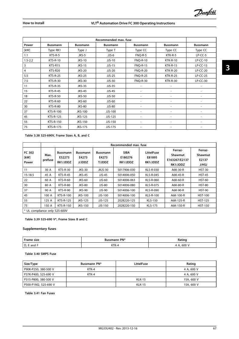
Recommended max. fuse
Power Bussmann Bussmann Bussmann Bussmann Bussmann Bussmann
[kW] Type RK1 Type J Type T Type CC Type CC Type CC
1.1 KTS-R-5 JKS-5 JJS-6 FNQ-R-5 KTK-R-5 LP-CC-5
1.5-2.2 KTS-R-10 JKS-10 JJS-10 FNQ-R-10 KTK-R-10 LP-CC-10
3 KTS-R15 JKS-15 JJS-15 FNQ-R-15 KTK-R-15 LP-CC-15
4 KTS-R20 JKS-20 JJS-20 FNQ-R-20 KTK-R-20 LP-CC-20
5.5 KTS-R-25 JKS-25 JJS-25 FNQ-R-25 KTK-R-25 LP-CC-25
7.5 KTS-R-30 JKS-30 JJS-30 FNQ-R-30 KTK-R-30 LP-CC-30
11 KTS-R-35 JKS-35 JJS-35 - - -
15 KTS-R-45 JKS-45 JJS-45 - - -
18 KTS-R-50 JKS-50 JJS-50 - - -
22 KTS-R-60 JKS-60 JJS-60 - - -
30 KTS-R-80 JKS-80 JJS-80 - - -
37 KTS-R-100 JKS-100 JJS-100 - - -
45 KTS-R-125 JKS-125 JJS-125 - - -
55 KTS-R-150 JKS-150 JJS-150 - - -
75 KTS-R-175 JKS-175 JJS-175 - - -
Table 3.38 525-690V, Frame Sizes A, B, and C
Recommended max. fuse
FC 302[kW]Power
Max.prefuse
BussmannE52273
RK1/JDDZ
BussmannE4273J/JDDZ
BussmannE4273
T/JDDZ
SIBAE180276
RK1/JDDZ
LittelFuseE81895
RK1/JDDZ
Ferraz-Shawmut
E163267/E2137RK1/JDDZ
Ferraz-Shawmut
E2137J/HSJ
11 30 A KTS-R-30 JKS-30 JKJS-30 5017906-030 KLS-R-030 A6K-30-R HST-30
15-18.5 45 A KTS-R-45 JKS-45 JJS-45 5014006-050 KLS-R-045 A6K-45-R HST-45
22 60 A KTS-R-60 JKS-60 JJS-60 5014006-063 KLS-R-060 A6K-60-R HST-60
30 80 A KTS-R-80 JKS-80 JJS-80 5014006-080 KLS-R-075 A6K-80-R HST-80
37 90 A KTS-R-90 JKS-90 JJS-90 5014006-100 KLS-R-090 A6K-90-R HST-90
45 100 A KTS-R-100 JKS-100 JJS-100 5014006-100 KLS-R-100 A6K-100-R HST-100
55 125 A KTS-R-125 JKS-125 JJS-125 2028220-125 KLS-150 A6K-125-R HST-125
75 150 A KTS-R-150 JKS-150 JJS-150 2028220-150 KLS-175 A6K-150-R HST-150
* UL compliance only 525-600V
Table 3.39 525-690 V*, Frame Sizes B and C
Supplementary fuses
Frame size Bussmann PN* Rating
D, E and F KTK-4 4 A, 600 V
Table 3.40 SMPS Fuse
Size/Type Bussmann PN* LittelFuse Rating
P90K-P250, 380-500 V KTK-4 4 A, 600 V
P37K-P400, 525-690 V KTK-4 4 A, 600 V
P315-P800, 380-500 V KLK-15 15A, 600 V
P500-P1M2, 525-690 V KLK-15 15A, 600 V
Table 3.41 Fan Fuses
How to Install VLT® Automation Drive FC 300 Operating Instructions
MG33U402 - Rev. 2013-12-16 67
3 3
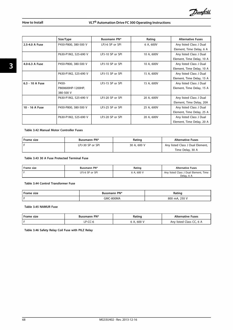
Size/Type Bussmann PN* Rating Alternative Fuses
2.5-4.0 A Fuse P450-P800, 380-500 V LPJ-6 SP or SPI 6 A, 600V Any listed Class J DualElement, Time Delay, 6 A
P630-P1M2, 525-690 V LPJ-10 SP or SPI 10 A, 600V Any listed Class J DualElement, Time Delay, 10 A
4.0-6.3 A Fuse P450-P800, 380-500 V LPJ-10 SP or SPI 10 A, 600V Any listed Class J DualElement, Time Delay, 10 A
P630-P1M2, 525-690 V LPJ-15 SP or SPI 15 A, 600V Any listed Class J DualElement, Time Delay, 15 A
6.3 - 10 A Fuse P450-P800600HP-1200HP,380-500 V
LPJ-15 SP or SPI 15 A, 600V Any listed Class J DualElement, Time Delay, 15 A
P630-P1M2, 525-690 V LPJ-20 SP or SPI 20 A, 600V Any listed Class J DualElement, Time Delay, 20A
10 - 16 A Fuse P450-P800, 380-500 V LPJ-25 SP or SPI 25 A, 600V Any listed Class J DualElement, Time Delay, 25 A
P630-P1M2, 525-690 V LPJ-20 SP or SPI 20 A, 600V Any listed Class J DualElement, Time Delay, 20 A
Table 3.42 Manual Motor Controller Fuses
Frame size Bussmann PN* Rating Alternative Fuses
F LPJ-30 SP or SPI 30 A, 600 V Any listed Class J Dual Element,Time Delay, 30 A
Table 3.43 30 A Fuse Protected Terminal Fuse
Frame size Bussmann PN* Rating Alternative Fuses
F LPJ-6 SP or SPI 6 A, 600 V Any listed Class J Dual Element, TimeDelay, 6 A
Table 3.44 Control Transformer Fuse
Frame size Bussmann PN* Rating
F GMC-800MA 800 mA, 250 V
Table 3.45 NAMUR Fuse
Frame size Bussmann PN* Rating Alternative Fuses
F LP-CC-6 6 A, 600 V Any listed Class CC, 6 A
Table 3.46 Safety Relay Coil Fuse with PILZ Relay
How to Install VLT® Automation Drive FC 300 Operating Instructions
68 MG33U402 - Rev. 2013-12-16
33

3.5.14 Mains Disconnectors - Frame Size D, E and F
Frame size Power Type
380-500 V
D1/D3 P90K-P110 ABB OT200U12-91
D2/D4 P132-P200 ABB OT400U12-91
E1/E2 P250 ABB OT600U03
E1/E2 P315-P400 ABB OT800U03
F3 P450 Merlin Gerin NPJF36000S12AAYP
F3 P500-P630 Merlin Gerin NRKF36000S20AAYP
F4 P710-P800 Merlin Gerin NRKF36000S20AAYP
525-690 V
D1/D3 P90K-P132 ABB OT200U12-91
D2/D4 P160-P315 ABB OT400U12-91
E1/E2 P355-P560 ABB OETL-NF600A
F3 P630-P710 Merlin Gerin NPJF36000S12AAYP
F3 P800 Merlin Gerin NRKF36000S20AAYP
F4 P900-P1M2 Merlin Gerin NRKF36000S20AAYP
Table 3.47 Mains Disconnector Types
3.5.15 F-Frame Circuit Breakers
Framesize Power & voltage Type Default breaker settings
Trip level [A] Time [s]
F3P450 380-500 V & P630-P710
525-690 VMerlin Gerin
NPJF36120U31AABSCYP 1200 0.5
F3P500-P630 380-500 V & P800
525-690 VMerlin Gerin
NRJF36200U31AABSCYP 2000 0.5
F4P710 380-500 V & P900-P1M2
525-690 VMerlin Gerin
NRJF36200U31AABSCYP 2000 0.5
F4 P800 380-500 VMerlin Gerin
NRJF36250U31AABSCYP 2500 0.5
Table 3.48 Circuit Breakers Types
3.5.16 F-Frame Mains Contactors
Frame size Power & voltage Type
F3 P450-P500 380-500 V & P630-P800 525-690 V Eaton XTCE650N22A
F3 P560 380-500 V Eaton XTCE820N22A
F3 P630380-500 V Eaton XTCEC14P22B
F4 P900 525-690 V Eaton XTCE820N22A
F4 P710-P800 380-500 V & P1M2 525-690 V Eaton XTCEC14P22B
Table 3.49 Mains Contactor Types
WARNINGCustomer supplied 230 V supply required for Mains Contactors.
How to Install VLT® Automation Drive FC 300 Operating Instructions
MG33U402 - Rev. 2013-12-16 69
3 3
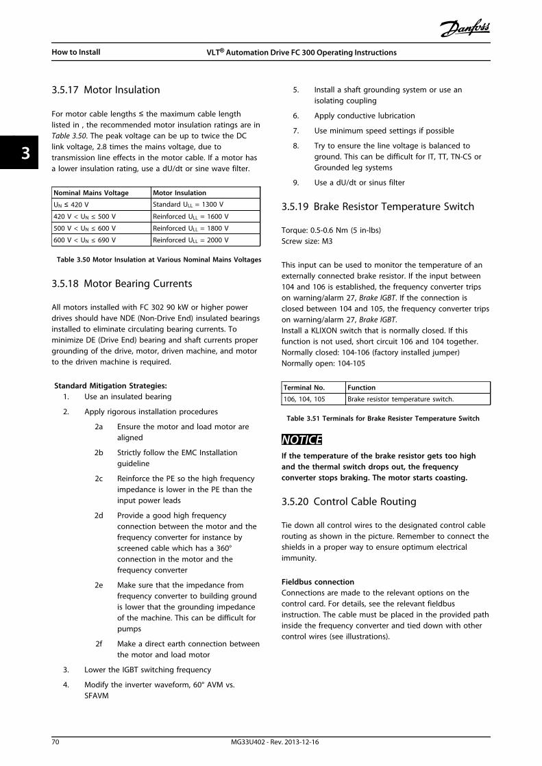
3.5.17 Motor Insulation
For motor cable lengths ≤ the maximum cable lengthlisted in , the recommended motor insulation ratings are inTable 3.50. The peak voltage can be up to twice the DClink voltage, 2.8 times the mains voltage, due totransmission line effects in the motor cable. If a motor hasa lower insulation rating, use a dU/dt or sine wave filter.
Nominal Mains Voltage Motor Insulation
UN ≤ 420 V Standard ULL = 1300 V
420 V < UN ≤ 500 V Reinforced ULL = 1600 V
500 V < UN ≤ 600 V Reinforced ULL = 1800 V
600 V < UN ≤ 690 V Reinforced ULL = 2000 V
Table 3.50 Motor Insulation at Various Nominal Mains Voltages
3.5.18 Motor Bearing Currents
All motors installed with FC 302 90 kW or higher powerdrives should have NDE (Non-Drive End) insulated bearingsinstalled to eliminate circulating bearing currents. Tominimize DE (Drive End) bearing and shaft currents propergrounding of the drive, motor, driven machine, and motorto the driven machine is required.
Standard Mitigation Strategies:1. Use an insulated bearing
2. Apply rigorous installation procedures
2a Ensure the motor and load motor arealigned
2b Strictly follow the EMC Installationguideline
2c Reinforce the PE so the high frequencyimpedance is lower in the PE than theinput power leads
2d Provide a good high frequencyconnection between the motor and thefrequency converter for instance byscreened cable which has a 360°connection in the motor and thefrequency converter
2e Make sure that the impedance fromfrequency converter to building groundis lower that the grounding impedanceof the machine. This can be difficult forpumps
2f Make a direct earth connection betweenthe motor and load motor
3. Lower the IGBT switching frequency
4. Modify the inverter waveform, 60° AVM vs.SFAVM
5. Install a shaft grounding system or use anisolating coupling
6. Apply conductive lubrication
7. Use minimum speed settings if possible
8. Try to ensure the line voltage is balanced toground. This can be difficult for IT, TT, TN-CS orGrounded leg systems
9. Use a dU/dt or sinus filter
3.5.19 Brake Resistor Temperature Switch
Torque: 0.5-0.6 Nm (5 in-lbs)Screw size: M3
This input can be used to monitor the temperature of anexternally connected brake resistor. If the input between104 and 106 is established, the frequency converter tripson warning/alarm 27, Brake IGBT. If the connection isclosed between 104 and 105, the frequency converter tripson warning/alarm 27, Brake IGBT.Install a KLIXON switch that is normally closed. If thisfunction is not used, short circuit 106 and 104 together.Normally closed: 104-106 (factory installed jumper)Normally open: 104-105
Terminal No. Function
106, 104, 105 Brake resistor temperature switch.
Table 3.51 Terminals for Brake Resister Temperature Switch
NOTICEIf the temperature of the brake resistor gets too highand the thermal switch drops out, the frequencyconverter stops braking. The motor starts coasting.
3.5.20 Control Cable Routing
Tie down all control wires to the designated control cablerouting as shown in the picture. Remember to connect theshields in a proper way to ensure optimum electricalimmunity.
Fieldbus connectionConnections are made to the relevant options on thecontrol card. For details, see the relevant fieldbusinstruction. The cable must be placed in the provided pathinside the frequency converter and tied down with othercontrol wires (see illustrations).
How to Install VLT® Automation Drive FC 300 Operating Instructions
70 MG33U402 - Rev. 2013-12-16
33

176F
A24
6.10
U/T1 96-DC 88
R/L1 91S/L2 92
T/L3 93
+DC 89
V/T2 97 W/13
Illustration 3.65 Control Card Wiring Path for the D3. ControlCard Wiring for the D1, D2, D4, E1 and E2 use the same Path
130B
B187
.10
1
Illustration 3.66 Control Card Wiring Path for the F1/F3.Control Card Wiring for the F2/F4 use the same Path
In the Chassis (IP00) and NEMA 1 units, it is also possibleto connect the fieldbus from the top of the unit as shownin the following pictures. On the NEMA 1 unit a coverplate must be removed.Kit number for fieldbus top connection: 176F1742
130B
A86
7.10
Probus Option A
FC300 Service
Illustration 3.67 Top Connection for Fieldbus.
130B
B255
.10
Illustration 3.68
130B
B256
.10
Illustration 3.69
How to Install VLT® Automation Drive FC 300 Operating Instructions
MG33U402 - Rev. 2013-12-16 71
3 3

Installation of 24 V external DC SupplyTorque: 0.5 - 0.6 Nm (5 in-lbs)Screw size: M3
No. Function
35 (-), 36 (+) 24 V external DC supply
Table 3.52 Terminals for 24 V External DC Supply
24 V DC external supply can be used as low-voltage supplyto the control card and any option cards installed. Thisenables full operation of the LCP (including parametersetting) without connection to mains. Note that a warningof low voltage is given when 24 V DC has been connected;however, there is no tripping.
WARNINGUse 24 V DC supply of type PELV to ensure correctgalvanic isolation (type PELV) on the control terminals ofthe frequency converter.
3.5.21 Access to Control Terminals
All terminals to the control cables are located beneath theLCP. They are accessed by opening the door of the IP21/IP54 version or removing the covers of the IP00 version.
3.5.22 Electrical Installation, ControlTerminals
To connect the cable to the terminal1. Strip insulation by about 9-10 mm
130B
A15
0.10
9 - 10 mm
(0.37 in)
Illustration 3.70 Stripping of Insulation
2. Insert a screwdriver1) in the square hole.
3. Insert the cable in the adjacent circular hole.
130B
T312
.10
Illustration 3.71
4. Remove the screwdriver. The cable is nowmounted in the terminal.
To remove the cable from the terminal1. Insert a screw driver1) in the square hole.
2. Pull out the cable.
130B
T311
.10
Illustration 3.72
1) Max. 0.4 x 2.5 mm
130B
T306
.10
Illustration 3.73
How to Install VLT® Automation Drive FC 300 Operating Instructions
72 MG33U402 - Rev. 2013-12-16
33

3.5.23 Electrical Installation, Control Cables
Switch Mode Power Supply
10Vdc15mA
24Vdc130/200mA
Analog Output0/4-20 mA
50 (+10 V OUT)
S201
S202
ON/I=0-20mA OFF/U=0-10V
+10 Vdc
-10 Vdc+10 Vdc
0/4-20 mA
-10 Vdc+10 Vdc0/4-20 mA
53 (A IN)
54 (A IN )
55 (COM A IN )
(COM A OUT) 39
(A OUT) 42
12 (+24V OUT )
13 (+24V OUT )
18 (D IN)
19 (D IN )
20 (COM D IN)
27 (D IN/OUT )
24 V
24 V
OV
OV
29 (D IN/OUT )
32 (D IN )
33 (D IN )
37 (D IN )
5 6 7 8 5 6 7 8
11
CI45MODULE
CI45MODULE
CI45MODULE
CI45MODULE
CI45MODULE
12 13 14 11 12 13 14 11 12 13 14 11 12 13 14 11 12 13 14
15 16 17 1815 16 17 1815 16 17 1815 16 17 1815 16 17 18
5 6 7 8 5 6 7 8 5 6 7 8
1 12 23 34 4 1 2 3 4 1 2 3 4 1 2 3 4
P 5-00
24V (NPN) 0V (PNP)
24V (NPN) 0V (PNP)
24V (NPN) 0V (PNP)
24V (NPN) 0V (PNP)
24V (NPN) 0V (PNP)
24V (NPN) 0V (PNP)
ON=TerminatedOFF=Open
(PNP) = Source(NPN) = Sink
RS-485
(COM RS-485) 61
(P RS-485) 68
(N RS-485) 69RS - 485Interface
S801
S801
5V
ON
ON
ON
1
1
12
2
2
CONTROL CARD CONNCECTION
130B
B759
.10
Illustration 3.74
A=Analog, D=Digital*Terminal 37 (optional) is used for Safe Torque Off. For Safe Torque Off installation instructions, refer to the Safe Torque OffOperating Instructions for Danfoss VLT® Frequency Converters. Terminal 37 is not included in FC 301 (except enclosure typeA1). Relay 2 and terminal 29 have no function in FC 301.**Do not connect cable screen.
How to Install VLT® Automation Drive FC 300 Operating Instructions
MG33U402 - Rev. 2013-12-16 73
3 3

EXTERNAL BRAKE
FUSE
A2
W
W
U
U
V
V
W
U
V
C14
C13
117118
+ -
EXTERNAL BRAKE
EXTERNAL BRAKE
EXTERNAL BRAKE
CONTROL CARD PIN 20(TERMINAL JUMPERED TOGETHER)
CUSTOMER SUPPLIED(TERMINAL JUMPERED TOGETHER)
MCB 113 PIN X46/1
MCB 113 PIN X46/3
MCB 113 PIN X46/5
MCB 113 PIN X46/7
MCB 113 PIN X46/9
MCB 113 PIN X46/11
MCB 113 PIN X46/13
MCB 113 PIN X47/1
MCB 113 PIN X47/3
MCB 113 PIN X47/2
MCB 113 PIN X47/4
MCB 113 PIN X47/6
MCB 113 PIN X47/5
MCB 113 PIN X47/7
MCB 113 PIN X47/9
MCB 113 PIN X47/8
MCB 113 PIN X45/1
MCB 113 PIN X45/2
MCB 113 PIN X45/3
MCB 113 PIN X45/4 AUX FAN AUX FAN
TB3 INVERTER 2
TB3 INVERTER 2
R-
R-
R+
R+
TB3 INVERTER 1
TB3 INVERTER 1
PILZTERMINALS
REGEN TERMINALS
MCB 113 PIN 12
MCB 112 PIN 1
MCB 112 PIN 2
CONTROL CARD PIN 37
CONTROL CARD PIN 53
CONTROL CARD PIN 55
TB08 PIN 01
TB08 PIN 02
TB08 PIN 04
TB08 PIN 05
11
1
1
2
2
3
3
4
5
5
3
3
10
12
13
14
15
16
17
18
30
31
32
33
34
35
36
37
38
39
40
41
42
50
51
60
61
62
63
90
91
11
TB7
L1 L1L2 L2
100 101 102
81
81
2
1
3
96
96
96
97
97
97
98
98
TB4
TB8
98
82
82
103
CUSTOMER SUPPLIED 24V RET.
CUSTOMERSUPPLIED 24V
130B
B760
.11
NA
MU
R Te
rmin
al D
eni
tion
2
81
82
EXTERNAL BRAKE
EXTERNAL BRAKE
W
U
V
4
96
97
98
81
82
R-
R+ R+
R-
Illustration 3.75 Diagram Showing all Electrical Terminals with NAMUR Option shown in Dotted Line Box
How to Install VLT® Automation Drive FC 300 Operating Instructions
74 MG33U402 - Rev. 2013-12-16
33
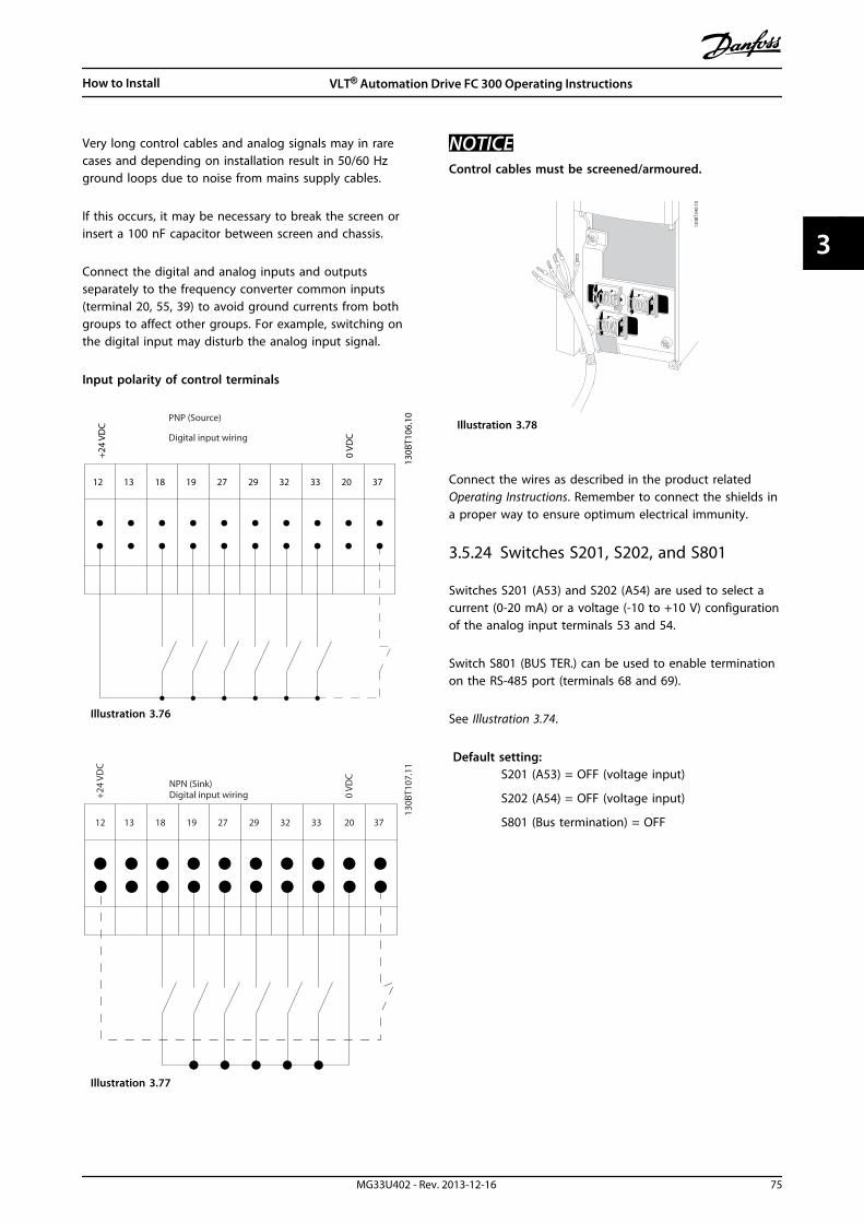
Very long control cables and analog signals may in rarecases and depending on installation result in 50/60 Hzground loops due to noise from mains supply cables.
If this occurs, it may be necessary to break the screen orinsert a 100 nF capacitor between screen and chassis.
Connect the digital and analog inputs and outputsseparately to the frequency converter common inputs(terminal 20, 55, 39) to avoid ground currents from bothgroups to affect other groups. For example, switching onthe digital input may disturb the analog input signal.
Input polarity of control terminals
12 13 18 19 27 29 32 33 20 37
+24
VDC
0 VD
C
130B
T106
.10PNP (Source)
Digital input wiring
Illustration 3.76
NPN (Sink)Digital input wiring
12 13 18 19 27 29 32 33 20 37
+24
VDC
0 VD
C
130B
T107
.11
Illustration 3.77
NOTICEControl cables must be screened/armoured.
130B
T340
.10
Illustration 3.78
Connect the wires as described in the product relatedOperating Instructions. Remember to connect the shields ina proper way to ensure optimum electrical immunity.
3.5.24 Switches S201, S202, and S801
Switches S201 (A53) and S202 (A54) are used to select acurrent (0-20 mA) or a voltage (-10 to +10 V) configurationof the analog input terminals 53 and 54.
Switch S801 (BUS TER.) can be used to enable terminationon the RS-485 port (terminals 68 and 69).
See Illustration 3.74.
Default setting:S201 (A53) = OFF (voltage input)
S202 (A54) = OFF (voltage input)
S801 (Bus termination) = OFF
How to Install VLT® Automation Drive FC 300 Operating Instructions
MG33U402 - Rev. 2013-12-16 75
3 3

NOTICEWhen changing the function of S201, S202 or S801 becareful not to use force for the switch over. It isrecommended to remove the LCP fixture (cradle) whenoperating the switches. The switches must not beoperated with power on the frequency converter.
130B
T310
.11
Illustration 3.79
3.6 Connection Examples
3.6.1 Start/Stop
Terminal 18 = 5-10 Terminal 18 Digital Input [8] StartTerminal 27 = 5-12 Terminal 27 Digital Input [0] Nooperation (Default coast inverse)Terminal 37 = Safe Torque Off
12 13 18 37 130B
A15
5.12
322719 29 33 20
P 5-
12 [0
]
P 5-
10 [8
]
Start/Stop
+24V
Speed
Safe Stop
Start/Stop[18]
Illustration 3.80
3.6.2 Pulse Start/Stop
Terminal 18 = 5-10 Terminal 18 Digital Input [9] LatchedstartTerminal 27= 5-12 Terminal 27 Digital Input [6] Stop inverseTerminal 37 = Safe Torque Off
12 13 18 37
130B
A15
6.12
322719 29 33 20
P 5
- 12
[6]
P 5
- 10[
9]
+24V
Speed
Start Stop inverse Safe Stop
Start (18)
Start (27)
Illustration 3.81
3.6.3 Speed Up/Down
Terminals 29/32 = Speed up/downTerminal 18 = 5-10 Terminal 18 Digital Input [9]Start (default)
Terminal 27 = 5-12 Terminal 27 Digital Input [19]Freeze reference
Terminal 29 = 5-13 Terminal 29 Digital Input [21]Speed up
Terminal 32 = 5-14 Terminal 32 Digital Input [22]Speed down
NOTICETerminal 29 only in FC x02 (x=series type).
12
18
27
29
32
37
+24V
Par. 5-10
Par. 5-12
Par. 5-13
Par. 5-14
130B
A02
1.12
Illustration 3.82 Speed Up/Down
How to Install VLT® Automation Drive FC 300 Operating Instructions
76 MG33U402 - Rev. 2013-12-16
33
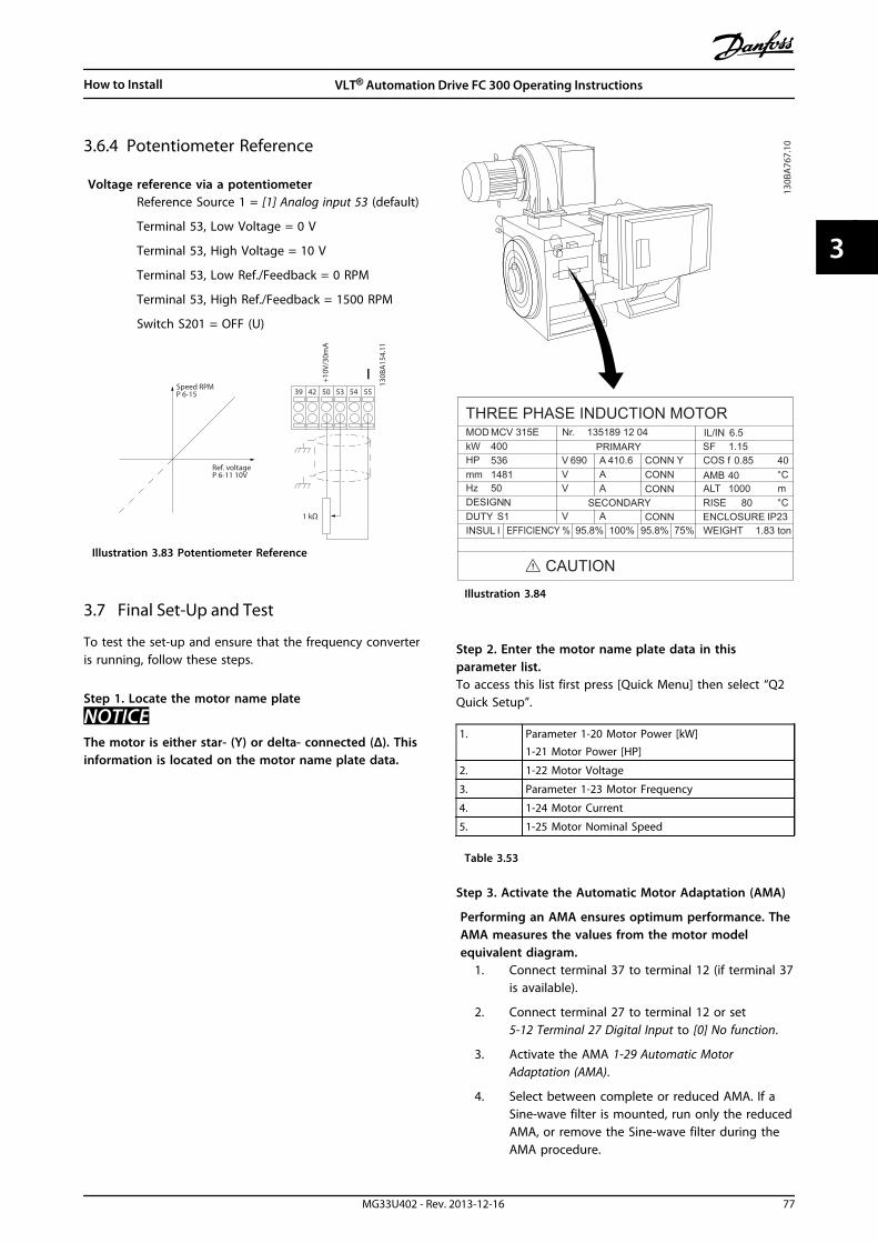
3.6.4 Potentiometer Reference
Voltage reference via a potentiometerReference Source 1 = [1] Analog input 53 (default)
Terminal 53, Low Voltage = 0 V
Terminal 53, High Voltage = 10 V
Terminal 53, Low Ref./Feedback = 0 RPM
Terminal 53, High Ref./Feedback = 1500 RPM
Switch S201 = OFF (U)
130B
A15
4.11
555039 42 53 54Speed RPMP 6-15
1 kΩ
+10V
/30m
A
Ref. voltageP 6-11 10V
Illustration 3.83 Potentiometer Reference
3.7 Final Set-Up and Test
To test the set-up and ensure that the frequency converteris running, follow these steps.
Step 1. Locate the motor name plate
NOTICEThe motor is either star- (Y) or delta- connected (Δ). Thisinformation is located on the motor name plate data.
THREE PHASE INDUCTION MOTOR
kW 400MOD MCV 315E Nr. 135189 12 04
PRIMARY
SECONDARY
V 690 AV AV A
V A
410.6 CONN YCONNCONN
CONN ENCLOSURE
CAUTION
COS f
ALTRISE
m
SF 1.150.85
AMB 401000
80
°C
°CIP23
40
IL/IN 6.5
HP 536mm 1481HzDESIGN
50N
DUTYINSUL WEIGHT 1.83 tonEFFICIENCY % 95.8% 95.8% 75%100%
S1I
130B
A76
7.10
Illustration 3.84
Step 2. Enter the motor name plate data in thisparameter list.To access this list first press [Quick Menu] then select “Q2Quick Setup”.
1. Parameter 1-20 Motor Power [kW]1-21 Motor Power [HP]
2. 1-22 Motor Voltage
3. Parameter 1-23 Motor Frequency
4. 1-24 Motor Current
5. 1-25 Motor Nominal Speed
Table 3.53
Step 3. Activate the Automatic Motor Adaptation (AMA)
Performing an AMA ensures optimum performance. TheAMA measures the values from the motor modelequivalent diagram.
1. Connect terminal 37 to terminal 12 (if terminal 37is available).
2. Connect terminal 27 to terminal 12 or set5-12 Terminal 27 Digital Input to [0] No function.
3. Activate the AMA 1-29 Automatic MotorAdaptation (AMA).
4. Select between complete or reduced AMA. If aSine-wave filter is mounted, run only the reducedAMA, or remove the Sine-wave filter during theAMA procedure.
How to Install VLT® Automation Drive FC 300 Operating Instructions
MG33U402 - Rev. 2013-12-16 77
3 3
5. Press [OK]. The display shows Press [Hand On] tostart.
6. Press [Hand On]. A progress bar indicates if theAMA is in progress.
Stop the AMA during operation1. Press [Off] - the frequency converter enters into
alarm mode and the display shows that the AMAwas terminated by the user.
Successful AMA1. The display shows Press [OK] to finish AMA.
2. Press [OK] to exit the AMA state.
Unsuccessful AMA1. The frequency converter enters into alarm mode.
A description of the alarm can be found inchapter 6 Warnings and Alarms.
2. "Report Value” in the [Alarm Log] shows the lastmeasuring sequence carried out by the AMA,before the frequency converter entered alarmmode. This number along with the description ofthe alarm assists in troubleshooting. If contactingDanfoss for service, make sure to mentionnumber and alarm description.
NOTICEUnsuccessful AMA is often caused by incorrectlyregistered motor name plate data or a too big differencebetween the motor power size and the frequencyconverter power size.
Step 4. Set speed limit and ramp timeParameter 3-02 Minimum Reference
Parameter 3-03 Maximum Reference
Set up the desired limits for speed and ramp time4-11 Motor Speed Low Limit [RPM] or 4-12 MotorSpeed Low Limit [Hz]
4-13 Motor Speed High Limit [RPM] or 4-14 MotorSpeed High Limit [Hz]
Parameter 3-41 Ramp 1 Ramp Up Time
Parameter 3-42 Ramp 1 Ramp Down Time
3.8 Additional Connections
3.8.1 Mechanical Brake Control
In hoisting/lowering applications, it is necessary to beable to control an electro-mechanical brake:
• Control the brake using any relay output ordigital output (terminal 27 or 29).
• Keep the output closed (voltage-free) as long asthe frequency converter is unable to support themotor, for example due to the load being tooheavy.
• Select [32] Mechanical brake control in parametergroup 5-4* Relays for applications with an electro-mechanical brake.
• The brake is released when the motor currentexceeds the preset value in 2-20 Release BrakeCurrent.
• The brake is engaged when the output frequencyis less than the frequency set in 2-21 ActivateBrake Speed [RPM] or 2-22 Activate Brake Speed[Hz], and only if the frequency converter carriesout a stop command.
If the frequency converter is in alarm mode or in an over-voltage situation, the mechanical brake immediately cutsin.
3.8.2 Parallel Connection of Motors
The frequency converter can control several parallel-connected motors. The total current consumption of themotors must not exceed the rated output current IM,N forthe frequency converter.
How to Install VLT® Automation Drive FC 300 Operating Instructions
78 MG33U402 - Rev. 2013-12-16
33

NOTICEInstallations with cables connected in a common joint asin Illustration 3.85, is only recommended for short cablelengths.
NOTICEWhen motors are connected in parallel, 1-29 AutomaticMotor Adaptation (AMA) cannot be used.
NOTICEThe electronic thermal relay (ETR) of the frequencyconverter cannot be used as motor protection for theindividual motor in systems with parallel-connectedmotors. Provide further motor protection by e.g.thermistors in each motor or individual thermal relays(circuit breakers are not suitable as protection).
LC lter
130B
A17
0.10
Illustration 3.85
Problems may arise at start and at low RPM values if motorsizes are widely different because small motors' relativelyhigh ohmic resistance in the stator calls for a highervoltage at start and at low RPM values.
3.8.3 Motor Thermal Protection
The electronic thermal relay in the frequency converter hasreceived UL-approval for single motor protection, when1-90 Motor Thermal Protectionis set for ETR Trip and1-24 Motor Current is set to the rated motor current (seemotor name plate).For thermal motor protection it is also possible to use theMCB 112 PTC Thermistor Card option. This card providesATEX certificate to protect motors in explosion hazardousareas, Zone 1/21 and Zone 2/22. When 1-90 Motor ThermalProtection is set to [20] ATEX ETR is combined with the useof MCB 112, it is possible to control an Ex-e motor inexplosion hazardous areas. Consult the programmingguide for details on how to set up the frequency converterfor safe operation of Ex-e motors.
How to Install VLT® Automation Drive FC 300 Operating Instructions
MG33U402 - Rev. 2013-12-16 79
3 3

4 How to Programme
4.1 The Graphical and Numerical LCP
The easiest programming of the frequency converter isperformed by the graphical LCP (LCP 102). Consult thefrequency converter Design Guide, when using the NumericLocal Control Panel (LCP 101).
The control panel is divided into 4 functional groups:1. Graphical display with Status lines.
2. Menu keys and indicator lights - changingparameters and switching between displayfunctions.
3. Navigation keys and indicator lights (LEDs).
4. Operation keys and indicator lights (LEDs).
All data is displayed in a graphical LCP display, which canshow up to 5 items of operating data while displaying[Status].
Display lines:a. Status line: Status messages displaying icons and
graphic.
b. Line 1-2: Operator data lines displaying datadefined or selected by the user. By pressing[Status], up to one extra line can be added.
c. Status line: Status messages displaying text.
NOTICEIf some operation is delaying the start-up, the LCPdisplays the INITIALISING message until it is ready.Adding or removing options may delay the start-up. Auto
on ResetHand
on O
StatusQuickMenu
MainMenu
AlarmLog
Back
Cancel
InfoOK
Status 1(0)
1234rpm 10,4A 43,5Hz
Run OK
43,5Hz
On
Alarm
Warn.
130B
A01
8.13
1
2
3
4
b
a
c
Illustration 4.1 Control Panel (LCP)
How to Programme VLT® Automation Drive FC 300 Operating Instructions
80 MG33U402 - Rev. 2013-12-16
44

4.1.1 How to Programme on the NumericalLocal Control Panel
The following instructions are valid for the numerical LCP(LCP 101):
The control panel is divided into 4 functional groups:1. Numerical display.
2. Menu keys and indicator lights - changingparameters and switching between displayfunctions.
3. Navigation keys and indicator lights (LEDs).
4. Operation keys and indicator lights (LEDs).
130B
A19
1.10
1
Auto on
ResetHand on
O
Menu
Status QuickSetup
MainMenu
Back
2
3
4
OKOn
Alarm
Warn.
Setup
Illustration 4.2
How to Programme VLT® Automation Drive FC 300 Operating Instructions
MG33U402 - Rev. 2013-12-16 81
4 4

4.1.2 Initial Commissioning
The easiest way of carrying out the initial commissioning is by pressing [Quick Menu] and following the quick set-upprocedure using LCP 102 (read Table 4.1 from left to right). The example applies to open loop applications.
Press
QuickMenu Q2 Quick Menu OK
Parameter 0-01 Language OK Set language
Parameter 1-20 Motor Power [kW] OK Set Motor nameplate power
1-22 Motor Voltage OK Set Nameplate voltage
Parameter 1-23 Motor Frequency OK Set Nameplate frequency
1-24 Motor Current OK Set Nameplate current
1-25 Motor Nominal Speed OK Set Nameplate speed in RPM
5-12 Terminal 27 Digital Input OK
If terminal default is Coastinverse it is possible to changethis setting to No function. Noconnection to terminal 27 isthen needed for running AMA
1-29 Automatic Motor Adaptation(AMA)
OK
Set desired AMA function.Enable complete AMA isrecommended
Parameter 3-02 Minimum Reference OKSet the minimum speed of themotor shaft
Parameter 3-03 Maximum Reference OKSet the maximum speed of themotor shaft
Parameter 3-41 Ramp 1 Ramp UpTime
OK
Set the ramping up time withreference to synchronousmotor speed, ns
Parameter 3-42 Ramp 1 Ramp DownTime
OK
Set the ramping down timewith reference to synchronousmotor speed, ns
3-13 Reference Site OKSet the site from where thereference must work
Table 4.1 Quick Set-up Procedure
How to Programme VLT® Automation Drive FC 300 Operating Instructions
82 MG33U402 - Rev. 2013-12-16
44
Another easy way of commissioning the frequencyconverter is by using the Smart Application Setup (SAS),which can also be found under the Quick Menu. Followthe indications on the successive screens for setting up theapplications listed.
[Info] can be used throughout the SAS to see helpinformation for various selections, settings, and messages.The following 3 applications are included:
• Mechanical Brake
• Conveyor
• Pump/Fan
The following 4 field-busses can be selected:
• Profibus
• Profinet
• DeviceNet
• EthernetIP
NOTICEThe start conditions are ignored while in the wizard.
NOTICEThe Smart Set-up runs automatically on the first power-up of the frequency converter or after a reset to factorysettings. If no action is taken, the SAS screen automat-ically disappears after 10 min.
4.2 Quick Setup
0-01 Language
Option: Function:Defines the language to be used in thedisplay. The frequency converter isdelivered with 4 different languagepackages English and German are includedin all packages. English cannot be erasedor manipulated.
[0] * English Part of Language packages 1 - 4
[1] Deutsch Part of Language packages 1 - 4
[2] Francais Part of Language package 1
[3] Dansk Part of Language package 1
[4] Spanish Part of Language package 1
[5] Italiano Part of Language package 1
[6] Svenska Part of Language package 1
[7] Nederlands Part of Language package 1
[10] Chinese Part of Language package 2
[20] Suomi Part of Language package 1
0-01 Language
Option: Function:[22] English US Part of Language package 4
[27] Greek Part of Language package 4
[28] Bras.port Part of Language package 4
[36] Slovenian Part of Language package 3
[39] Korean Part of Language package 2
[40] Japanese Part of Language package 2
[41] Turkish Part of Language package 4
[42] Trad.Chinese Part of Language package 2
[43] Bulgarian Part of Language package 3
[44] Srpski Part of Language package 3
[45] Romanian Part of Language package 3
[46] Magyar Part of Language package 3
[47] Czech Part of Language package 3
[48] Polski Part of Language package 4
[49] Russian Part of Language package 3
[50] Thai Part of Language package 2
[51] BahasaIndonesia
Part of Language package 2
[52] Hrvatski Part of Language package 3
1-20 Motor Power [kW]
Range: Function:Sizerelated*
[ 0.09 -3000.00kW]
NOTICEThis parameter cannot be adjustedwhile the motor is running.
Enter the nominal motor power in kWaccording to the motor nameplate data.The default value corresponds to thenominal rated output of the unit.This parameter is visible in LCP if0-03 Regional Settings is [0] International.
NOTICE4 sizes down, 1 size up fromnominal unit rating.
1-22 Motor Voltage
Range: Function:Sizerelated*
[ 10 -1000 V]
Enter the nominal motor voltageaccording to the motor nameplatedata. The default value corresponds tothe nominal rated output of the unit.
How to Programme VLT® Automation Drive FC 300 Operating Instructions
MG33U402 - Rev. 2013-12-16 83
4 4

1-23 Motor Frequency
Range: Function:Sizerelated*
[20 -1000Hz]
Min - Max motor frequency: 20-1000 Hz.Select the motor frequency value from themotor nameplate data. If a value differentfrom 50 Hz or 60 Hz is selected, adapt theload independent settings in 1-50 MotorMagnetisation at Zero Speed to 1-53 ModelShift Frequency. For 87 Hz operation with230/400 V motors, set the nameplate datafor 230 V/50 Hz. To run at 87 Hz, adapt4-13 Motor Speed High Limit [RPM] and parameter 3-03 Maximum Reference.
1-24 Motor Current
Range: Function:Sizerelated*
[ 0.10 -10000.00 A]
Enter the nominal motor currentvalue from the motor nameplatedata. This data is used forcalculating motor torque, motorthermal protection etc.
1-25 Motor Nominal Speed
Range: Function:Size related* [100 - 60000
RPM]Enter the nominal motor speedvalue from the motor nameplatedata. This data is used forcalculating automatic motorcompensations.
5-12 Terminal 27 Digital Input
Option: Function:[2] * Coast inverse Functions are described under parameter
group 5-1* Digital Inputs
1-29 Automatic Motor Adaptation (AMA)
Option: Function:The AMA function optimises dynamic motorperformance by automatically optimising theadvanced motor parameters (1-30 StatorResistance (Rs) to 1-35 Main Reactance (Xh)) atmotor standstill.Activate the AMA function by pressing [Handon] after selecting [1] Enable complete AMA or[2] Enable reduced AMA. See alsochapter 3.7.1 Final Set-Up and Test. After anormal sequence, the display reads: "Press [OK]to finish AMA". After pressing [OK], thefrequency converter is ready for operation.This parameter cannot be adjusted while themotor is running.
[0]*
OFF
[1] EnablecompleteAMA
Performs AMA of the stator resistance RS, the
rotor resistance Rr, the stator leakage reactance
1-29 Automatic Motor Adaptation (AMA)
Option: Function:X1, the rotor leakage reactance X2 and the main
reactance Xh.
FC 301: The complete AMA does not include Xh
measurement for FC 301. Instead, the Xh value
is determined from the motor database.1-35 Main Reactance (Xh) may be adjusted toobtain optimal start performance.
[2] EnablereducedAMA
Performs a reduced AMA of the statorresistance Rs in the system only. Select this
option if an LC filter is used between thefrequency converter and the motor.
Note:• For the best adaptation of the frequency
converter, run AMA on a cold motor.
• AMA cannot be performed while the motor isrunning.
• AMA cannot be performed on permanent magnetmotors.
NOTICEIt is important to set motor parameter group 1-2*correctly, since these form part of the AMA algorithm.An AMA must be performed to achieve optimumdynamic motor performance. It may take up to 10 min,depending on the power rating of the motor.
NOTICEAvoid generating external torque during AMA.
NOTICEIf one of the settings in parameter group 1-2* MotorData is changed, 1-30 Stator Resistance (Rs) to 1-39 MotorPoles return to default setting.
3-02 Minimum Reference
Range: Function:Sizerelated*
[ -999999.999 -par. 3-03ReferenceFeed-backUnit]
Enter the minimum reference. Theminimum reference is the lowestvalue obtainable by summing allreferences.Minimum reference is active onlywhen 3-00 Reference Range is set to[0] Min.- Max.The minimum reference unitmatches:
• The configuration of1-00 Configuration Mode:
How to Programme VLT® Automation Drive FC 300 Operating Instructions
84 MG33U402 - Rev. 2013-12-16
44
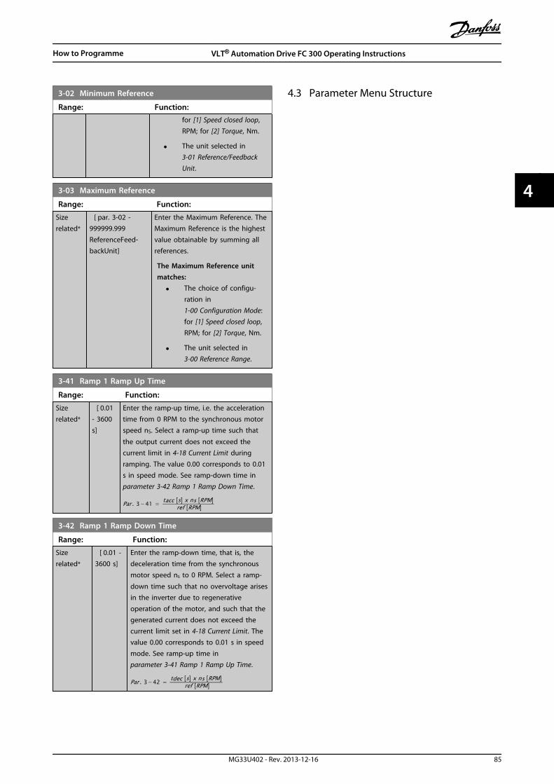
3-02 Minimum Reference
Range: Function:for [1] Speed closed loop,RPM; for [2] Torque, Nm.
• The unit selected in3-01 Reference/FeedbackUnit.
3-03 Maximum Reference
Range: Function:Sizerelated*
[ par. 3-02 -999999.999ReferenceFeed-backUnit]
Enter the Maximum Reference. TheMaximum Reference is the highestvalue obtainable by summing allreferences.
The Maximum Reference unitmatches:
• The choice of configu-ration in1-00 Configuration Mode:for [1] Speed closed loop,RPM; for [2] Torque, Nm.
• The unit selected in3-00 Reference Range.
3-41 Ramp 1 Ramp Up Time
Range: Function:Sizerelated*
[ 0.01- 3600s]
Enter the ramp-up time, i.e. the accelerationtime from 0 RPM to the synchronous motorspeed nS. Select a ramp-up time such that
the output current does not exceed thecurrent limit in 4-18 Current Limit duringramping. The value 0.00 corresponds to 0.01s in speed mode. See ramp-down time in parameter 3-42 Ramp 1 Ramp Down Time.
Par . 3−41 = tacc s x ns RPM ref RPM
3-42 Ramp 1 Ramp Down Time
Range: Function:Sizerelated*
[ 0.01 -3600 s]
Enter the ramp-down time, that is, thedeceleration time from the synchronousmotor speed ns to 0 RPM. Select a ramp-
down time such that no overvoltage arisesin the inverter due to regenerativeoperation of the motor, and such that thegenerated current does not exceed thecurrent limit set in 4-18 Current Limit. Thevalue 0.00 corresponds to 0.01 s in speedmode. See ramp-up time in parameter 3-41 Ramp 1 Ramp Up Time.
Par . 3−42 = tdec s x ns RPM ref RPM
4.3 Parameter Menu Structure
How to Programme VLT® Automation Drive FC 300 Operating Instructions
MG33U402 - Rev. 2013-12-16 85
4 4

0-**
Ope
ratio
n /
Dis
play
0-0*
Basi
c Se
ttin
gs0-
01La
ngua
ge0-
02M
otor
Spe
ed U
nit
0-03
Regi
onal
Set
tings
0-04
Ope
ratin
g S
tate
at
Pow
er-u
p (H
and)
0-09
Perf
orm
ance
Mon
itor
0-1*
Set-
up O
pera
tions
0-10
Act
ive
Set-
up0-
11Ed
it S
et-u
p0-
12Th
is S
et-u
p L
inke
d t
o0-
13Re
adou
t: L
inke
d S
et-u
ps0-
14Re
adou
t: E
dit
Set-
ups
/ Ch
anne
l0-
15Re
adou
t: a
ctua
l set
up0-
2*LC
P D
ispl
ay0-
20D
ispl
ay L
ine
1.1
Smal
l0-
21D
ispl
ay L
ine
1.2
Smal
l0-
22D
ispl
ay L
ine
1.3
Smal
l0-
23D
ispl
ay L
ine
2 La
rge
0-24
Dis
play
Lin
e 3
Larg
e0-
25M
y Pe
rson
al M
enu
0-3*
LCP
Cus
tom
Rea
dout
0-30
Uni
t fo
r U
ser-
defin
ed R
eado
ut0-
31M
in V
alue
of
Use
r-de
fined
Rea
dout
0-32
Max
Val
ue o
f U
ser-
defin
ed R
eado
ut0-
37D
ispl
ay T
ext
10-
38D
ispl
ay T
ext
20-
39D
ispl
ay T
ext
30-
4*LC
P K
eypa
d0-
40[H
and
on]
Key
on
LCP
0-41
[Off]
Key
on
LCP
0-42
[Aut
o o
n] K
ey o
n L
CP0-
43[R
eset
] Ke
y on
LCP
0-44
[Off/
Rese
t] K
ey o
n L
CP0-
45[D
rive
Bypa
ss]
Key
on L
CP0-
5*Co
py/S
ave
0-50
LCP
Cop
y0-
51Se
t-up
Cop
y0-
6*Pa
ssw
ord
0-60
Mai
n M
enu
Pas
swor
d0-
61A
cces
s to
Mai
n M
enu
w/o
Pas
swor
d0-
65Q
uick
Men
u P
assw
ord
0-66
Acc
ess
to Q
uick
Men
u w
/o P
assw
ord
0-67
Bus
Pass
wor
d A
cces
s0-
68Sa
fety
Par
amet
ers
Pass
wor
d0-
69Pa
ssw
ord
Pro
tect
ion
of
Safe
tyPa
ram
eter
s1-
**Lo
ad a
nd M
otor
1-0*
Gen
eral
Set
tings
1-00
Conf
igur
atio
n M
ode
1-01
Mot
or C
ontr
ol P
rinci
ple
1-02
Flux
Mot
or F
eedb
ack
Sour
ce1-
03To
rque
Cha
ract
eris
tics
1-04
Ove
rload
Mod
e1-
05Lo
cal M
ode
Conf
igur
atio
n1-
06Cl
ockw
ise
Dire
ctio
n1-
07M
otor
Ang
le O
ffset
Adj
ust
1-1*
Spec
ial S
ettin
gs1-
10M
otor
Con
stru
ctio
n
1-11
Mot
or M
odel
1-14
Dam
ping
Gai
n1-
15Lo
w S
peed
Filt
er T
ime
Cons
t.1-
16H
igh
Spe
ed F
ilter
Tim
e Co
nst.
1-17
Volta
ge fi
lter
time
cons
t.1-
2*M
otor
Dat
a1-
20M
otor
Pow
er [k
W]
1-21
Mot
or P
ower
[HP]
1-22
Mot
or V
olta
ge1-
23M
otor
Fre
quen
cy1-
24M
otor
Cur
rent
1-25
Mot
or N
omin
al S
peed
1-26
Mot
or C
ont.
Rat
ed T
orqu
e1-
29A
utom
atic
Mot
or A
dapt
atio
n (A
MA
)1-
3*A
dv. M
otor
Dat
a1-
30St
ator
Res
ista
nce
(Rs)
1-31
Roto
r Re
sist
ance
(Rr)
1-33
Stat
or L
eaka
ge R
eact
ance
(X1)
1-34
Roto
r Le
akag
e Re
acta
nce
(X2)
1-35
Mai
n R
eact
ance
(Xh)
1-36
Iron
Los
s Re
sist
ance
(Rfe
)1-
37d-
axis
Indu
ctan
ce (L
d)1-
38q-
axis
Indu
ctan
ce (L
q)1-
39M
otor
Pol
es1-
40Ba
ck E
MF
at 1
000
RPM
1-41
Mot
or A
ngle
Offs
et1-
44d-
axis
Indu
ctan
ce S
at. (
LdSa
t)1-
45q-
axis
Indu
ctan
ce S
at. (
LqSa
t)1-
46Po
sitio
n D
etec
tion
Gai
n1-
47Lo
w S
peed
Tor
que
Calib
ratio
n1-
48In
duct
ance
Sat
. Poi
nt1-
5*Lo
ad In
dep.
Set
ting
1-50
Mot
or M
agne
tisat
ion
at
Zero
Spe
ed1-
51M
in S
peed
Nor
mal
Mag
netis
ing
[RPM
]1-
52M
in S
peed
Nor
mal
Mag
netis
ing
[Hz]
1-53
Mod
el S
hift
Fre
quen
cy1-
54Vo
ltage
red
uctio
n in
fiel
dwea
keni
ng1-
55U
/f C
hara
cter
istic
- U
1-56
U/f
Cha
ract
eris
tic -
F1-
58Fl
ysta
rt T
est
Puls
es C
urre
nt1-
59Fl
ysta
rt T
est
Puls
es F
requ
ency
1-6*
Load
Dep
en. S
ettin
g1-
60Lo
w S
peed
Loa
d C
ompe
nsat
ion
1-61
Hig
h S
peed
Loa
d C
ompe
nsat
ion
1-62
Slip
Com
pens
atio
n1-
63Sl
ip C
ompe
nsat
ion
Tim
e Co
nsta
nt1-
64Re
sona
nce
Dam
peni
ng1-
65Re
sona
nce
Dam
peni
ng T
ime
Cons
tant
1-66
Min
. Cur
rent
at
Low
Spe
ed1-
67Lo
ad T
ype
1-68
Min
imum
Iner
tia1-
69M
axim
um In
ertia
1-7*
Star
t A
djus
tmen
ts1-
70PM
Sta
rt M
ode
1-71
Star
t D
elay
1-72
Star
t Fu
nctio
n1-
73Fl
ying
Sta
rt1-
74St
art
Spee
d [R
PM]
1-75
Star
t Sp
eed
[Hz]
1-76
Star
t Cu
rren
t1-
8*St
op A
djus
tmen
ts1-
80Fu
nctio
n a
t St
op1-
81M
in S
peed
for
Func
tion
at
Stop
[RPM
]1-
82M
in S
peed
for
Func
tion
at
Stop
[Hz]
1-83
Prec
ise
Stop
Fun
ctio
n1-
84Pr
ecis
e St
op C
ount
er V
alue
1-85
Prec
ise
Stop
Spe
ed C
ompe
nsat
ion
Del
ay1-
9*M
otor
Tem
pera
ture
1-90
Mot
or T
herm
al P
rote
ctio
n1-
91M
otor
Ext
erna
l Fan
1-93
Ther
mis
tor
Reso
urce
1-94
ATE
X E
TR c
ur.li
m. s
peed
red
uctio
n1-
95KT
Y S
enso
r Ty
pe1-
96KT
Y T
herm
isto
r Re
sour
ce1-
97KT
Y T
hres
hold
leve
l1-
98A
TEX
ETR
inte
rpol
. poi
nts
freq
.1-
99A
TEX
ETR
inte
rpol
poi
nts
curr
ent
2-**
Brak
es2-
0*D
C-Br
ake
2-00
DC
Hol
d C
urre
nt2-
01D
C B
rake
Cur
rent
2-02
DC
Bra
king
Tim
e2-
03D
C B
rake
Cut
In S
peed
[RPM
]2-
04D
C B
rake
Cut
In S
peed
[Hz]
2-05
Max
imum
Ref
eren
ce2-
06Pa
rkin
g C
urre
nt2-
07Pa
rkin
g T
ime
2-1*
Brak
e En
ergy
Fun
ct.
2-10
Brak
e Fu
nctio
n2-
11Br
ake
Resi
stor
(ohm
)2-
12Br
ake
Pow
er L
imit
(kW
)2-
13Br
ake
Pow
er M
onito
ring
2-15
Brak
e Ch
eck
2-16
AC
bra
ke M
ax. C
urre
nt2-
17O
ver-
volta
ge C
ontr
ol2-
18Br
ake
Chec
k Co
nditi
on2-
19O
ver-
volta
ge G
ain
2-2*
Mec
hani
cal B
rake
2-20
Rele
ase
Brak
e Cu
rren
t2-
21A
ctiv
ate
Brak
e Sp
eed
[RPM
]2-
22A
ctiv
ate
Brak
e Sp
eed
[Hz]
2-23
Act
ivat
e Br
ake
Del
ay2-
24St
op D
elay
2-25
Brak
e Re
leas
e Ti
me
2-26
Torq
ue R
ef2-
27To
rque
Ram
p T
ime
2-28
Gai
n B
oost
Fac
tor
2-29
Torq
ue R
amp
Dow
n T
ime
2-30
Posi
tion
P S
tart
Pro
port
iona
l Gai
n2-
31Sp
eed
PID
Sta
rt P
ropo
rtio
nal G
ain
2-32
Spee
d P
ID S
tart
Inte
gral
Tim
e2-
33Sp
eed
PID
Sta
rt L
owpa
ss F
ilter
Tim
e3-
**Re
fere
nce
/ Ra
mps
3-0*
Refe
renc
e Li
mits
3-00
Refe
renc
e Ra
nge
3-01
Refe
renc
e/Fe
edba
ck U
nit
3-02
Min
imum
Ref
eren
ce
3-03
Max
imum
Ref
eren
ce3-
04Re
fere
nce
Func
tion
3-1*
Refe
renc
es3-
10Pr
eset
Ref
eren
ce3-
11Jo
g S
peed
[Hz]
3-12
Catc
h u
p/sl
ow D
own
Val
ue3-
13Re
fere
nce
Site
3-14
Pres
et R
elat
ive
Refe
renc
e3-
15Re
fere
nce
Reso
urce
13-
16Re
fere
nce
Reso
urce
23-
17Re
fere
nce
Reso
urce
33-
18Re
lativ
e Sc
alin
g R
efer
ence
Res
ourc
e3-
19Jo
g S
peed
[RPM
]3-
4*Ra
mp
13-
40Ra
mp
1 T
ype
3-41
Ram
p 1
Ram
p U
p T
ime
3-42
Ram
p 1
Ram
p D
own
Tim
e3-
45Ra
mp
1 S
-ram
p R
atio
at
Acc
el. S
tart
3-46
Ram
p 1
S-r
amp
Rat
io a
t A
ccel
. End
3-47
Ram
p 1
S-r
amp
Rat
io a
t D
ecel
. Sta
rt3-
48Ra
mp
1 S
-ram
p R
atio
at
Dec
el. E
nd3-
5*Ra
mp
23-
50Ra
mp
2 T
ype
3-51
Ram
p 2
Ram
p U
p T
ime
3-52
Ram
p 2
Ram
p D
own
Tim
e3-
55Ra
mp
2 S
-ram
p R
atio
at
Acc
el. S
tart
3-56
Ram
p 2
S-r
amp
Rat
io a
t A
ccel
. End
3-57
Ram
p 2
S-r
amp
Rat
io a
t D
ecel
. Sta
rt3-
58Ra
mp
2 S
-ram
p R
atio
at
Dec
el. E
nd3-
6*Ra
mp
33-
60Ra
mp
3 T
ype
3-61
Ram
p 3
Ram
p u
p T
ime
3-62
Ram
p 3
Ram
p d
own
Tim
e3-
65Ra
mp
3 S
-ram
p R
atio
at
Acc
el. S
tart
3-66
Ram
p 3
S-r
amp
Rat
io a
t A
ccel
. End
3-67
Ram
p 3
S-r
amp
Rat
io a
t D
ecel
. Sta
rt3-
68Ra
mp
3 S
-ram
p R
atio
at
Dec
el. E
nd3-
7*Ra
mp
43-
70Ra
mp
4 T
ype
3-71
Ram
p 4
Ram
p u
p T
ime
3-72
Ram
p 4
Ram
p D
own
Tim
e3-
75Ra
mp
4 S
-ram
p R
atio
at
Acc
el. S
tart
3-76
Ram
p 4
S-r
amp
Rat
io a
t A
ccel
. End
3-77
Ram
p 4
S-r
amp
Rat
io a
t D
ecel
. Sta
rt3-
78Ra
mp
4 S
-ram
p R
atio
at
Dec
el. E
nd3-
8*O
ther
Ram
ps3-
80Jo
g R
amp
Tim
e3-
81Q
uick
Sto
p R
amp
Tim
e3-
82Q
uick
Sto
p R
amp
Typ
e3-
83Q
uick
Sto
p S
-ram
p R
atio
at
Dec
el. S
tart
3-84
Qui
ck S
top
S-r
amp
Rat
io a
t D
ecel
. End
3-9*
Dig
ital P
ot.M
eter
3-90
Step
Siz
e3-
91Ra
mp
Tim
e3-
92Po
wer
Res
tore
3-93
Max
imum
Lim
it3-
94M
inim
um L
imit
3-95
Ram
p D
elay
4-**
Lim
its /
War
ning
s
4-1*
Mot
or L
imits
4-10
Mot
or S
peed
Dire
ctio
n4-
11M
otor
Spe
ed L
ow L
imit
[RPM
]4-
12M
otor
Spe
ed L
ow L
imit
[Hz]
4-13
Mot
or S
peed
Hig
h L
imit
[RPM
]4-
14M
otor
Spe
ed H
igh
Lim
it [H
z]4-
16To
rque
Lim
it M
otor
Mod
e4-
17To
rque
Lim
it G
ener
ator
Mod
e4-
18Cu
rren
t Li
mit
4-19
Max
Out
put
Freq
uenc
y4-
2*Li
mit
Fac
tors
4-20
Torq
ue L
imit
Fac
tor
Sour
ce4-
21Sp
eed
Lim
it F
acto
r So
urce
4-3*
Mot
or S
peed
Mon
.4-
30M
otor
Fee
dbac
k Lo
ss F
unct
ion
4-31
Mot
or F
eedb
ack
Spee
d E
rror
4-32
Mot
or F
eedb
ack
Loss
Tim
eout
4-34
Trac
king
Err
or F
unct
ion
4-35
Trac
king
Err
or4-
36Tr
acki
ng E
rror
Tim
eout
4-37
Trac
king
Err
or R
ampi
ng4-
38Tr
acki
ng E
rror
Ram
ping
Tim
eout
4-39
Trac
king
Err
or A
fter
Ram
ping
Tim
eout
4-5*
Adj
. War
ning
s4-
50W
arni
ng C
urre
nt L
ow4-
51W
arni
ng C
urre
nt H
igh
4-52
War
ning
Spe
ed L
ow4-
53W
arni
ng S
peed
Hig
h4-
54W
arni
ng R
efer
ence
Low
4-55
War
ning
Ref
eren
ce H
igh
4-56
War
ning
Fee
dbac
k Lo
w4-
57W
arni
ng F
eedb
ack
Hig
h4-
58M
issi
ng M
otor
Pha
se F
unct
ion
4-6*
Spee
d B
ypas
s4-
60By
pass
Spe
ed F
rom
[RPM
]4-
61By
pass
Spe
ed F
rom
[Hz]
4-62
Bypa
ss S
peed
To
[RPM
]4-
63By
pass
Spe
ed T
o [H
z]5-
**D
igita
l In/
Out
5-0*
Dig
ital I
/O m
ode
5-00
Dig
ital I
/O M
ode
5-01
Term
inal
27
Mod
e5-
02Te
rmin
al 2
9 M
ode
5-1*
Dig
ital I
nput
s5-
10Te
rmin
al 1
8 D
igita
l Inp
ut5-
11Te
rmin
al 1
9 D
igita
l Inp
ut5-
12Te
rmin
al 2
7 D
igita
l Inp
ut5-
13Te
rmin
al 2
9 D
igita
l Inp
ut5-
14Te
rmin
al 3
2 D
igita
l Inp
ut5-
15Te
rmin
al 3
3 D
igita
l Inp
ut5-
16Te
rmin
al X
30/2
Dig
ital I
nput
5-17
Term
inal
X30
/3 D
igita
l Inp
ut5-
18Te
rmin
al X
30/4
Dig
ital I
nput
5-19
Term
inal
37
Safe
Sto
p5-
20Te
rmin
al X
46/1
Dig
ital I
nput
5-21
Term
inal
X46
/3 D
igita
l Inp
ut5-
22Te
rmin
al X
46/5
Dig
ital I
nput
5-23
Term
inal
X46
/7 D
igita
l Inp
ut5-
24Te
rmin
al X
46/9
Dig
ital I
nput
How to Programme VLT® Automation Drive FC 300 Operating Instructions
86 MG33U402 - Rev. 2013-12-16
44

5-25
Term
inal
X46
/11
Dig
ital I
nput
5-26
Term
inal
X46
/13
Dig
ital I
nput
5-3*
Dig
ital O
utpu
ts5-
30Te
rmin
al 2
7 D
igita
l Out
put
5-31
Term
inal
29
Dig
ital O
utpu
t5-
32Te
rm X
30/6
Dig
i Out
(MCB
101
)5-
33Te
rm X
30/7
Dig
i Out
(MCB
101
)5-
4*Re
lays
5-40
Func
tion
Rel
ay5-
41O
n D
elay
, Rel
ay5-
42O
ff D
elay
, Rel
ay5-
5*Pu
lse
Inpu
t5-
50Te
rm. 2
9 Lo
w F
requ
ency
5-51
Term
. 29
Hig
h F
requ
ency
5-52
Term
. 29
Low
Ref
./Fee
db. V
alue
5-53
Term
. 29
Hig
h R
ef./F
eedb
. Val
ue5-
54Pu
lse
Filte
r Ti
me
Cons
tant
#29
5-55
Term
. 33
Low
Fre
quen
cy5-
56Te
rm. 3
3 H
igh
Fre
quen
cy5-
57Te
rm. 3
3 Lo
w R
ef./F
eedb
. Val
ue5-
58Te
rm. 3
3 H
igh
Ref
./Fee
db. V
alue
5-59
Puls
e Fi
lter
Tim
e Co
nsta
nt #
335-
6*Pu
lse
Out
put
5-60
Term
inal
27
Puls
e O
utpu
t Va
riabl
e5-
62Pu
lse
Out
put
Max
Fre
q #
275-
63Te
rmin
al 2
9 Pu
lse
Out
put
Varia
ble
5-65
Puls
e O
utpu
t M
ax F
req
#29
5-66
Term
inal
X30
/6 P
ulse
Out
put
Varia
ble
5-68
Puls
e O
utpu
t M
ax F
req
#X3
0/6
5-7*
24V
Enc
oder
Inpu
t5-
70Te
rm 3
2/33
Pul
ses
Per
Revo
lutio
n5-
71Te
rm 3
2/33
Enc
oder
Dire
ctio
n5-
8*I/O
Opt
ions
5-80
AH
F Ca
p R
econ
nect
Del
ay5-
9*Bu
s Co
ntro
lled
5-90
Dig
ital &
Rel
ay B
us C
ontr
ol5-
93Pu
lse
Out
#27
Bus
Con
trol
5-94
Puls
e O
ut #
27 T
imeo
ut P
rese
t5-
95Pu
lse
Out
#29
Bus
Con
trol
5-96
Puls
e O
ut #
29 T
imeo
ut P
rese
t5-
97Pu
lse
Out
#X3
0/6
Bus
Cont
rol
5-98
Puls
e O
ut #
X30/
6 Ti
meo
ut P
rese
t6-
**A
nalo
g In
/Out
6-0*
Ana
log
I/O
Mod
e6-
00Li
ve Z
ero
Tim
eout
Tim
e6-
01Li
ve Z
ero
Tim
eout
Fun
ctio
n6-
1*A
nalo
g In
put
16-
10Te
rmin
al 5
3 Lo
w V
olta
ge6-
11Te
rmin
al 5
3 H
igh
Vol
tage
6-12
Term
inal
53
Low
Cur
rent
6-13
Term
inal
53
Hig
h C
urre
nt6-
14Te
rmin
al 5
3 Lo
w R
ef./F
eedb
. Val
ue6-
15Te
rmin
al 5
3 H
igh
Ref
./Fee
db. V
alue
6-16
Term
inal
53
Filte
r Ti
me
Cons
tant
6-2*
Ana
log
Inpu
t 2
6-20
Term
inal
54
Low
Vol
tage
6-21
Term
inal
54
Hig
h V
olta
ge6-
22Te
rmin
al 5
4 Lo
w C
urre
nt6-
23Te
rmin
al 5
4 H
igh
Cur
rent
6-24
Term
inal
54
Low
Ref
./Fee
db. V
alue
6-25
Term
inal
54
Hig
h R
ef./F
eedb
. Val
ue6-
26Te
rmin
al 5
4 Fi
lter
Tim
e Co
nsta
nt6-
3*A
nalo
g In
put
36-
30Te
rmin
al X
30/1
1 Lo
w V
olta
ge6-
31Te
rmin
al X
30/1
1 H
igh
Vol
tage
6-34
Term
. X30
/11
Low
Ref
./Fee
db. V
alue
6-35
Term
. X30
/11
Hig
h R
ef./F
eedb
. Val
ue6-
36Te
rm. X
30/1
1 Fi
lter
Tim
e Co
nsta
nt6-
4*A
nalo
g In
put
46-
40Te
rmin
al X
30/1
2 Lo
w V
olta
ge6-
41Te
rmin
al X
30/1
2 H
igh
Vol
tage
6-44
Term
. X30
/12
Low
Ref
./Fee
db. V
alue
6-45
Term
. X30
/12
Hig
h R
ef./F
eedb
. Val
ue6-
46Te
rm. X
30/1
2 Fi
lter
Tim
e Co
nsta
nt6-
5*A
nalo
g O
utpu
t 1
6-50
Term
inal
42
Out
put
6-51
Term
inal
42
Out
put
Min
Sca
le6-
52Te
rmin
al 4
2 O
utpu
t M
ax S
cale
6-53
Term
42
Out
put
Bus
Ctrl
6-54
Term
inal
42
Out
put
Tim
eout
Pre
set
6-55
Ana
log
Out
put
Filte
r6-
6*A
nalo
g O
utpu
t 2
6-60
Term
inal
X30
/8 O
utpu
t6-
61Te
rmin
al X
30/8
Min
. Sca
le6-
62Te
rmin
al X
30/8
Max
. Sca
le6-
63Te
rmin
al X
30/8
Bus
Con
trol
6-64
Term
inal
X30
/8 O
utpu
t Ti
meo
ut P
rese
t6-
7*A
nalo
g O
utpu
t 3
6-70
Term
inal
X45
/1 O
utpu
t6-
71Te
rmin
al X
45/1
Min
. Sca
le6-
72Te
rmin
al X
45/1
Max
. Sca
le6-
73Te
rmin
al X
45/1
Bus
Con
trol
6-74
Term
inal
X45
/1 O
utpu
t Ti
meo
ut P
rese
t6-
8*A
nalo
g O
utpu
t 4
6-80
Term
inal
X45
/3 O
utpu
t6-
81Te
rmin
al X
45/3
Min
. Sca
le6-
82Te
rmin
al X
45/3
Max
. Sca
le6-
83Te
rmin
al X
45/3
Bus
Con
trol
6-84
Term
inal
X45
/3 O
utpu
t Ti
meo
ut P
rese
t7-
**Co
ntro
llers
7-0*
Spee
d P
ID C
trl.
7-00
Spee
d P
ID F
eedb
ack
Sour
ce7-
02Sp
eed
PID
Pro
port
iona
l Gai
n7-
03Sp
eed
PID
Inte
gral
Tim
e7-
04Sp
eed
PID
Diff
eren
tiatio
n T
ime
7-05
Spee
d P
ID D
iff. G
ain
Lim
it7-
06Sp
eed
PID
Low
pass
Filt
er T
ime
7-07
Spee
d P
ID F
eedb
ack
Gea
r Ra
tio7-
08Sp
eed
PID
Fee
d F
orw
ard
Fac
tor
7-09
Spee
d P
ID E
rror
Cor
rect
ion
w/
Ram
p7-
1*To
rque
PI
Ctrl
.7-
12To
rque
PI P
ropo
rtio
nal G
ain
7-13
Torq
ue P
I Int
egra
tion
Tim
e7-
2*Pr
oces
s Ct
rl. F
eedb
7-20
Proc
ess
CL F
eedb
ack
1 Re
sour
ce7-
22Pr
oces
s CL
Fee
dbac
k 2
Reso
urce
7-3*
Proc
ess
PID
Ctr
l.7-
30Pr
oces
s PI
D N
orm
al/
Inve
rse
Cont
rol
7-31
Proc
ess
PID
Ant
i Win
dup
7-32
Proc
ess
PID
Sta
rt S
peed
7-33
Proc
ess
PID
Pro
port
iona
l Gai
n7-
34Pr
oces
s PI
D In
tegr
al T
ime
7-35
Proc
ess
PID
Diff
eren
tiatio
n T
ime
7-36
Proc
ess
PID
Diff
. Gai
n L
imit
7-38
Proc
ess
PID
Fee
d F
orw
ard
Fac
tor
7-39
On
Ref
eren
ce B
andw
idth
7-4*
Adv
. Pro
cess
PID
I7-
40Pr
oces
s PI
D I-
part
Res
et7-
41Pr
oces
s PI
D O
utpu
t N
eg. C
lam
p7-
42Pr
oces
s PI
D O
utpu
t Po
s. C
lam
p7-
43Pr
oces
s PI
D G
ain
Sca
le a
t M
in. R
ef.
7-44
Proc
ess
PID
Gai
n S
cale
at
Max
. Ref
.7-
45Pr
oces
s PI
D F
eed
Fw
d R
esou
rce
7-46
Proc
ess
PID
Fee
d F
wd
Nor
mal
/ In
v.Ct
rl.7-
48PC
D F
eed
For
war
d7-
49Pr
oces
s PI
D O
utpu
t N
orm
al/
Inv.
Ctr
l.7-
5*A
dv. P
roce
ss P
ID II
7-50
Proc
ess
PID
Ext
ende
d P
ID7-
51Pr
oces
s PI
D F
eed
Fw
d G
ain
7-52
Proc
ess
PID
Fee
d F
wd
Ram
p u
p7-
53Pr
oces
s PI
D F
eed
Fw
d R
amp
dow
n7-
56Pr
oces
s PI
D R
ef. F
ilter
Tim
e7-
57Pr
oces
s PI
D F
b. F
ilter
Tim
e8-
**Co
mm
. and
Opt
ions
8-0*
Gen
eral
Set
tings
8-01
Cont
rol S
ite8-
02Co
ntro
l Wor
d S
ourc
e8-
03Co
ntro
l Wor
d T
imeo
ut T
ime
8-04
Cont
rol W
ord
Tim
eout
Fun
ctio
n8-
05En
d-of
-Tim
eout
Fun
ctio
n8-
06Re
set
Cont
rol W
ord
Tim
eout
8-07
Dia
gnos
is T
rigge
r8-
08Re
adou
t Fi
lterin
g8-
1*Ct
rl. W
ord
Set
tings
8-10
Cont
rol W
ord
Pro
file
8-13
Conf
igur
able
Sta
tus
Wor
d S
TW8-
14Co
nfig
urab
le C
ontr
ol W
ord
CTW
8-17
Conf
igur
able
Ala
rm a
nd W
arni
ng W
ord
8-19
Prod
uct
Code
8-3*
FC P
ort
Sett
ings
8-30
Prot
ocol
8-31
Add
ress
8-32
FC P
ort
Baud
Rat
e8-
33Pa
rity
/ St
op B
its8-
34Es
timat
ed c
ycle
tim
e8-
35M
inim
um R
espo
nse
Del
ay8-
36M
ax R
espo
nse
Del
ay8-
37M
ax In
ter-
Char
Del
ay8-
4*FC
MC
pro
toco
l set
8-40
Tele
gram
Sel
ectio
n8-
41Pa
ram
eter
s fo
r Si
gnal
s8-
42PC
D W
rite
Conf
igur
atio
n8-
43PC
D R
ead
Con
figur
atio
n8-
5*D
igita
l/Bus
8-50
Coas
ting
Sel
ect
8-51
Qui
ck S
top
Sel
ect
8-52
DC
Bra
ke S
elec
t8-
53St
art
Sele
ct8-
54Re
vers
ing
Sel
ect
8-55
Set-
up S
elec
t8-
56Pr
eset
Ref
eren
ce S
elec
t8-
57Pr
ofid
rive
OFF
2 Se
lect
8-58
Prof
idriv
e O
FF3
Sele
ct8-
8*FC
Por
t D
iagn
ostic
s8-
80Bu
s M
essa
ge C
ount
8-81
Bus
Erro
r Co
unt
8-82
Slav
e M
essa
ges
Rcvd
8-83
Slav
e Er
ror
Coun
t8-
9*Bu
s Jo
g8-
90Bu
s Jo
g 1
Spe
ed8-
91Bu
s Jo
g 2
Spe
ed9-
**PR
OFI
driv
e9-
00Se
tpoi
nt9-
07A
ctua
l Val
ue9-
15PC
D W
rite
Conf
igur
atio
n9-
16PC
D R
ead
Con
figur
atio
n9-
18N
ode
Add
ress
9-22
Tele
gram
Sel
ectio
n9-
23Pa
ram
eter
s fo
r Si
gnal
s9-
27Pa
ram
eter
Edi
t9-
28Pr
oces
s Co
ntro
l9-
44Fa
ult
Mes
sage
Cou
nter
9-45
Faul
t Co
de9-
47Fa
ult
Num
ber
9-52
Faul
t Si
tuat
ion
Cou
nter
9-53
Prof
ibus
War
ning
Wor
d9-
63A
ctua
l Bau
d R
ate
9-64
Dev
ice
Iden
tific
atio
n9-
65Pr
ofile
Num
ber
9-67
Cont
rol W
ord
19-
68St
atus
Wor
d 1
9-71
Prof
ibus
Sav
e D
ata
Valu
es9-
72Pr
ofib
usD
riveR
eset
9-75
DO
Iden
tific
atio
n9-
80D
efin
ed P
aram
eter
s (1
)9-
81D
efin
ed P
aram
eter
s (2
)9-
82D
efin
ed P
aram
eter
s (3
)9-
83D
efin
ed P
aram
eter
s (4
)9-
84D
efin
ed P
aram
eter
s (5
)9-
90Ch
ange
d P
aram
eter
s (1
)9-
91Ch
ange
d P
aram
eter
s (2
)9-
92Ch
ange
d P
aram
eter
s (3
)9-
93Ch
ange
d P
aram
eter
s (4
)9-
94Ch
ange
d P
aram
eter
s (5
)9-
99Pr
ofib
us R
evis
ion
Cou
nter
10-*
*CA
N F
ield
bus
10-0
*Co
mm
on S
ettin
gs10
-00
CAN
Pro
toco
l10
-01
Baud
Rat
e Se
lect
10-0
2M
AC
ID10
-05
Read
out
Tran
smit
Err
or C
ount
er10
-06
Read
out
Rece
ive
Erro
r Co
unte
r10
-07
Read
out
Bus
Off
Cou
nter
10-1
*D
evic
eNet
10-1
0Pr
oces
s D
ata
Type
Sel
ectio
n
10-1
1Pr
oces
s D
ata
Conf
ig W
rite
10-1
2Pr
oces
s D
ata
Conf
ig R
ead
10-1
3W
arni
ng P
aram
eter
10-1
4N
et R
efer
ence
10-1
5N
et C
ontr
ol10
-2*
COS
Filte
rs10
-20
COS
Filte
r 1
10-2
1CO
S Fi
lter
210
-22
COS
Filte
r 3
10-2
3CO
S Fi
lter
410
-3*
Para
met
er A
cces
s10
-30
Arr
ay In
dex
10-3
1St
ore
Dat
a Va
lues
10-3
2D
evic
enet
Rev
isio
n10
-33
Stor
e A
lway
s10
-34
Dev
iceN
et P
rodu
ct C
ode
10-3
9D
evic
enet
F P
aram
eter
s10
-5*
CAN
open
10-5
0Pr
oces
s D
ata
Conf
ig W
rite.
10-5
1Pr
oces
s D
ata
Conf
ig R
ead.
12-*
*Et
hern
et12
-0*
IP S
ettin
gs12
-00
IP A
ddre
ss A
ssig
nmen
t12
-01
IP A
ddre
ss12
-02
Subn
et M
ask
12-0
3D
efau
lt G
atew
ay12
-04
DH
CP S
erve
r12
-05
Leas
e Ex
pire
s12
-06
Nam
e Se
rver
s12
-07
Dom
ain
Nam
e12
-08
Hos
t N
ame
12-0
9Ph
ysic
al A
ddre
ss12
-1*
Ethe
rnet
Lin
k Pa
ram
eter
s12
-10
Link
Sta
tus
12-1
1Li
nk D
urat
ion
12-1
2A
uto
Neg
otia
tion
12-1
3Li
nk S
peed
12-1
4Li
nk D
uple
x12
-2*
Proc
ess
Dat
a12
-20
Cont
rol I
nsta
nce
12-2
1Pr
oces
s D
ata
Conf
ig W
rite
12-2
2Pr
oces
s D
ata
Conf
ig R
ead
12-2
3Pr
oces
s D
ata
Conf
ig W
rite
Size
12-2
4Pr
oces
s D
ata
Conf
ig R
ead
Siz
e12
-27
Mas
ter
Add
ress
12-2
8St
ore
Dat
a Va
lues
12-2
9St
ore
Alw
ays
12-3
*Et
herN
et/IP
12-3
0W
arni
ng P
aram
eter
12-3
1N
et R
efer
ence
12-3
2N
et C
ontr
ol12
-33
CIP
Rev
isio
n12
-34
CIP
Pro
duct
Cod
e12
-35
EDS
Para
met
er12
-37
COS
Inhi
bit
Tim
er12
-38
COS
Filte
r12
-4*
Mod
bus
TCP
12-4
0St
atus
Par
amet
er12
-41
Slav
e M
essa
ge C
ount
How to Programme VLT® Automation Drive FC 300 Operating Instructions
MG33U402 - Rev. 2013-12-16 87
4 4

12-4
2Sl
ave
Exce
ptio
n M
essa
ge C
ount
12-5
*Et
herC
AT
12-5
0Co
nfig
ured
Sta
tion
Alia
s12
-51
Conf
igur
ed S
tatio
n A
ddre
ss12
-59
Ethe
rCA
T St
atus
12-6
*Et
hern
et P
ower
Link
12-6
0N
ode
ID12
-62
SDO
Tim
eout
12-6
3Ba
sic
Ethe
rnet
Tim
eout
12-6
6Th
resh
old
12-6
7Th
resh
old
Cou
nter
s12
-68
Cum
ulat
ive
Coun
ters
12-6
9Et
hern
et P
ower
Link
Sta
tus
12-8
*O
ther
Eth
erne
t Se
rvic
es12
-80
FTP
Ser
ver
12-8
1H
TTP
Ser
ver
12-8
2SM
TP S
ervi
ce12
-89
Tran
spar
ent
Sock
et C
hann
el P
ort
12-9
*A
dvan
ced
Eth
erne
t Se
rvic
es12
-90
Cabl
e D
iagn
ostic
12-9
1A
uto
Cro
ss O
ver
12-9
2IG
MP
Sno
opin
g12
-93
Cabl
e Er
ror
Leng
th12
-94
Broa
dcas
t St
orm
Pro
tect
ion
12-9
5Br
oadc
ast
Stor
m F
ilter
12-9
6Po
rt C
onfig
12-9
8In
terf
ace
Coun
ters
12-9
9M
edia
Cou
nter
s13
-**
Smar
t Lo
gic
13-0
*SL
C S
ettin
gs13
-00
SL C
ontr
olle
r M
ode
13-0
1St
art
Even
t13
-02
Stop
Eve
nt13
-03
Rese
t SL
C13
-1*
Com
para
tors
13-1
0Co
mpa
rato
r O
pera
nd13
-11
Com
para
tor
Ope
rato
r13
-12
Com
para
tor
Valu
e13
-1*
RS F
lip F
lops
13-1
5RS
-FF
Ope
rand
S13
-16
RS-F
F O
pera
nd R
13-2
*Ti
mer
s13
-20
SL C
ontr
olle
r Ti
mer
13-4
*Lo
gic
Rule
s13
-40
Logi
c Ru
le B
oole
an 1
13-4
1Lo
gic
Rule
Ope
rato
r 1
13-4
2Lo
gic
Rule
Boo
lean
213
-43
Logi
c Ru
le O
pera
tor
213
-44
Logi
c Ru
le B
oole
an 3
13-5
*St
ates
13-5
1SL
Con
trol
ler
Even
t13
-52
SL C
ontr
olle
r A
ctio
n14
-**
Spec
ial F
unct
ions
14-0
*In
vert
er S
witc
hing
14-0
0Sw
itchi
ng P
atte
rn14
-01
Switc
hing
Fre
quen
cy14
-03
Ove
rmod
ulat
ion
14-0
4PW
M R
ando
m14
-06
Dea
d T
ime
Com
pens
atio
n
14-1
*M
ains
On/
Off
14-1
0M
ains
Fai
lure
14-1
1M
ains
Vol
tage
at
Mai
ns F
ault
14-1
2Fu
nctio
n a
t M
ains
Imba
lanc
e14
-14
Kin.
Bac
kup
Tim
e O
ut14
-15
Kin.
Bac
kup
Trip
Rec
over
y Le
vel
14-2
*Tr
ip R
eset
14-2
0Re
set
Mod
e14
-21
Aut
omat
ic R
esta
rt T
ime
14-2
2O
pera
tion
Mod
e14
-24
Trip
Del
ay a
t Cu
rren
t Li
mit
14-2
5Tr
ip D
elay
at
Torq
ue L
imit
14-2
6Tr
ip D
elay
at
Inve
rter
Fau
lt14
-28
Prod
uctio
n S
ettin
gs14
-29
Serv
ice
Code
14-3
*Cu
rren
t Li
mit
Ctr
l.14
-30
Curr
ent
Lim
Ctr
l, Pr
opor
tiona
l Gai
n14
-31
Curr
ent
Lim
Ctr
l, In
tegr
atio
n T
ime
14-3
2Cu
rren
t Li
m C
trl,
Filte
r Ti
me
14-3
5St
all P
rote
ctio
n14
-36
Fiel
dwea
keni
ng F
unct
ion
14-4
*En
ergy
Opt
imis
ing
14-4
0VT
Lev
el14
-41
AEO
Min
imum
Mag
netis
atio
n14
-42
Min
imum
AEO
Fre
quen
cy14
-43
Mot
or C
osph
i14
-5*
Envi
ronm
ent
14-5
0RF
I Filt
er14
-51
DC
Lin
k Co
mpe
nsat
ion
14-5
2Fa
n C
ontr
ol14
-53
Fan
Mon
itor
14-5
5O
utpu
t Fi
lter
14-5
6Ca
paci
tanc
e O
utpu
t Fi
lter
14-5
7In
duct
ance
Out
put
Filte
r14
-59
Act
ual N
umbe
r of
Inve
rter
Uni
ts14
-7*
Com
patib
ility
14-7
2Le
gacy
Ala
rm W
ord
14-7
3Le
gacy
War
ning
Wor
d14
-74
Leg.
Ext
. Sta
tus
Wor
d14
-8*
Opt
ions
14-8
0O
ptio
n S
uppl
ied
by
Exte
rnal
24V
DC
14-8
9O
ptio
n D
etec
tion
14-9
*Fa
ult
Sett
ings
14-9
0Fa
ult
Leve
l15
-**
Dri
ve In
form
atio
n15
-0*
Ope
ratin
g D
ata
15-0
0O
pera
ting
hou
rs15
-01
Runn
ing
Hou
rs15
-02
kWh
Cou
nter
15-0
3Po
wer
Up'
s15
-04
Ove
r Te
mp'
s15
-05
Ove
r Vo
lt's
15-0
6Re
set
kWh
Cou
nter
15-0
7Re
set
Runn
ing
Hou
rs C
ount
er15
-1*
Dat
a Lo
g S
ettin
gs15
-10
Logg
ing
Sou
rce
15-1
1Lo
ggin
g In
terv
al15
-12
Trig
ger
Even
t15
-13
Logg
ing
Mod
e
15-1
4Sa
mpl
es B
efor
e Tr
igge
r15
-2*
His
tori
c Lo
g15
-20
His
toric
Log
: Eve
nt15
-21
His
toric
Log
: Val
ue15
-22
His
toric
Log
: Tim
e15
-3*
Faul
t Lo
g15
-30
Faul
t Lo
g: E
rror
Cod
e15
-31
Faul
t Lo
g: V
alue
15-3
2Fa
ult
Log:
Tim
e15
-4*
Dri
ve Id
entif
icat
ion
15-4
0FC
Typ
e15
-41
Pow
er S
ectio
n15
-42
Volta
ge15
-43
Soft
war
e Ve
rsio
n15
-44
Ord
ered
Typ
ecod
e St
ring
15-4
5A
ctua
l Typ
ecod
e St
ring
15-4
6Fr
eque
ncy
Conv
erte
r O
rder
ing
No
15-4
7Po
wer
Car
d O
rder
ing
No
15-4
8LC
P Id
No
15-4
9SW
ID C
ontr
ol C
ard
15-5
0SW
ID P
ower
Car
d15
-51
Freq
uenc
y Co
nver
ter
Seria
l Num
ber
15-5
3Po
wer
Car
d S
eria
l Num
ber
15-5
8Sm
art
Setu
p F
ilena
me
15-5
9CS
IV F
ilena
me
15-6
*O
ptio
n Id
ent
15-6
0O
ptio
n M
ount
ed15
-61
Opt
ion
SW
Ver
sion
15-6
2O
ptio
n O
rder
ing
No
15-6
3O
ptio
n S
eria
l No
15-7
0O
ptio
n in
Slo
t A
15-7
1Sl
ot A
Opt
ion
SW
Ver
sion
15-7
2O
ptio
n in
Slo
t B
15-7
3Sl
ot B
Opt
ion
SW
Ver
sion
15-7
4O
ptio
n in
Slo
t C0
/E0
15-7
5Sl
ot C
0/E0
Opt
ion
SW
Ver
sion
15-7
6O
ptio
n in
Slo
t C1
/E1
15-7
7Sl
ot C
1/E1
Opt
ion
SW
Ver
sion
15-8
*O
pera
ting
Dat
a II
15-8
0Fa
n R
unni
ng H
ours
15-8
1Pr
eset
Fan
Run
ning
Hou
rs15
-89
Conf
igur
atio
n C
hang
e Co
unte
r15
-9*
Para
met
er In
fo15
-92
Def
ined
Par
amet
ers
15-9
3M
odifi
ed P
aram
eter
s15
-98
Driv
e Id
entif
icat
ion
15-9
9Pa
ram
eter
Met
adat
a16
-**
Dat
a Re
adou
ts16
-0*
Gen
eral
Sta
tus
16-0
0Co
ntro
l Wor
d16
-01
Refe
renc
e [U
nit]
16-0
2Re
fere
nce
%16
-03
Stat
us W
ord
16-0
5M
ain
Act
ual V
alue
[%]
16-0
9Cu
stom
Rea
dout
16-1
*M
otor
Sta
tus
16-1
0Po
wer
[kW
]16
-11
Pow
er [h
p]16
-12
Mot
or V
olta
ge
16-1
3Fr
eque
ncy
16-1
4M
otor
cur
rent
16-1
5Fr
eque
ncy
[%]
16-1
6To
rque
[Nm
]16
-17
Spee
d [R
PM]
16-1
8M
otor
The
rmal
16-1
9KT
Y s
enso
r te
mpe
ratu
re16
-20
Mot
or A
ngle
16-2
1To
rque
[%]
Hig
h R
es.
16-2
2To
rque
[%]
16-2
3M
otor
Sha
ft P
ower
[kW
]16
-24
Calib
rate
d S
tato
r Re
sist
ance
16-2
5To
rque
[Nm
] H
igh
16-3
*D
rive
Sta
tus
16-3
0D
C L
ink
Volta
ge16
-32
Brak
e En
ergy
/s
16-3
3Br
ake
Ener
gy /
2 m
in16
-34
Hea
tsin
k Te
mp.
16-3
5In
vert
er T
herm
al16
-36
Inv.
Nom
. Cur
rent
16-3
7In
v. M
ax. C
urre
nt16
-38
SL C
ontr
olle
r St
ate
16-3
9Co
ntro
l Car
d T
emp.
16-4
0Lo
ggin
g B
uffe
r Fu
ll16
-41
LCP
Bot
tom
Sta
tusl
ine
16-4
5M
otor
Pha
se U
Cur
rent
16-4
6M
otor
Pha
se V
Cur
rent
16-4
7M
otor
Pha
se W
Cur
rent
16-4
8Sp
eed
Ref
. Aft
er R
amp
[RPM
]16
-49
Curr
ent
Faul
t So
urce
16-5
*Re
f. &
Fee
db.
16-5
0Ex
tern
al R
efer
ence
16-5
1Pu
lse
Refe
renc
e16
-52
Feed
back
[Uni
t]16
-53
Dig
i Pot
Ref
eren
ce16
-57
Feed
back
[RPM
]16
-6*
Inpu
ts &
Out
puts
16-6
0D
igita
l Inp
ut16
-61
Term
inal
53
Switc
h S
ettin
g16
-62
Ana
log
Inpu
t 53
16-6
3Te
rmin
al 5
4 Sw
itch
Set
ting
16-6
4A
nalo
g In
put
5416
-65
Ana
log
Out
put
42 [m
A]
16-6
6D
igita
l Out
put
[bin
]16
-67
Freq
. Inp
ut #
29 [H
z]16
-68
Freq
. Inp
ut #
33 [H
z]16
-69
Puls
e O
utpu
t #2
7 [H
z]16
-70
Puls
e O
utpu
t #2
9 [H
z]16
-71
Rela
y O
utpu
t [b
in]
16-7
2Co
unte
r A
16-7
3Co
unte
r B
16-7
4Pr
ec. S
top
Cou
nter
16-7
5A
nalo
g In
X30
/11
16-7
6A
nalo
g In
X30
/12
16-7
7A
nalo
g O
ut X
30/8
[mA
]16
-78
Ana
log
Out
X45
/1 [m
A]
16-7
9A
nalo
g O
ut X
45/3
[mA
]16
-8*
Fiel
dbus
& F
C P
ort
16-8
0Fi
eldb
us C
TW 1
16-8
2Fi
eldb
us R
EF 1
16-8
4Co
mm
. Opt
ion
STW
16-8
5FC
Por
t CT
W 1
16-8
6FC
Por
t RE
F 1
16-8
7Bu
s Re
adou
t A
larm
/War
ning
16-8
9Co
nfig
urab
le A
larm
/War
ning
Wor
d16
-9*
Dia
gnos
is R
eado
uts
16-9
0A
larm
Wor
d16
-91
Ala
rm W
ord
216
-92
War
ning
Wor
d16
-93
War
ning
Wor
d 2
16-9
4Ex
t. S
tatu
s W
ord
17-*
*Fe
edba
ck O
ptio
n17
-1*
Inc.
Enc
. Int
erfa
ce17
-10
Sign
al T
ype
17-1
1Re
solu
tion
(PPR
)17
-2*
Abs
. Enc
. Int
erfa
ce17
-20
Prot
ocol
Sel
ectio
n17
-21
Reso
lutio
n (P
ositi
ons/
Rev)
17-2
4SS
I Dat
a Le
ngth
17-2
5Cl
ock
Rate
17-2
6SS
I Dat
a Fo
rmat
17-3
4H
IPER
FACE
Bau
drat
e17
-5*
Reso
lver
Inte
rfac
e17
-50
Pole
s17
-51
Inpu
t Vo
ltage
17-5
2In
put
Freq
uenc
y17
-53
Tran
sfor
mat
ion
Rat
io17
-56
Enco
der
Sim
. Res
olut
ion
17-5
9Re
solv
er In
terf
ace
17-6
*M
onito
ring
and
App
.17
-60
Feed
back
Dire
ctio
n17
-61
Feed
back
Sig
nal M
onito
ring
18-*
*D
ata
Read
outs
218
-3*
Ana
log
Rea
dout
s18
-36
Ana
log
Inpu
t X4
8/2
[mA
]18
-37
Tem
p. In
put
X48/
418
-38
Tem
p. In
put
X48/
718
-39
Tem
p. In
put
X48/
1018
-6*
Inpu
ts &
Out
puts
218
-60
Dig
ital I
nput
218
-9*
PID
Rea
dout
s18
-90
Proc
ess
PID
Err
or18
-91
Proc
ess
PID
Out
put
18-9
2Pr
oces
s PI
D C
lam
ped
Out
put
18-9
3Pr
oces
s PI
D G
ain
Sca
led
Out
put
30-*
*Sp
ecia
l Fea
ture
s30
-0*
Wob
bler
30-0
0W
obbl
e M
ode
30-0
1W
obbl
e D
elta
Fre
quen
cy [H
z]30
-02
Wob
ble
Del
ta F
requ
ency
[%]
30-0
3W
obbl
e D
elta
Fre
q. S
calin
g R
esou
rce
30-0
4W
obbl
e Ju
mp
Fre
quen
cy [H
z]30
-05
Wob
ble
Jum
p F
requ
ency
[%]
30-0
6W
obbl
e Ju
mp
Tim
e30
-07
Wob
ble
Sequ
ence
Tim
e30
-08
Wob
ble
Up/
Dow
n T
ime
30-0
9W
obbl
e Ra
ndom
Fun
ctio
n30
-10
Wob
ble
Ratio
How to Programme VLT® Automation Drive FC 300 Operating Instructions
88 MG33U402 - Rev. 2013-12-16
44

30-1
1W
obbl
e Ra
ndom
Rat
io M
ax.
30-1
2W
obbl
e Ra
ndom
Rat
io M
in.
30-1
9W
obbl
e D
elta
Fre
q. S
cale
d30
-2*
Adv
. Sta
rt A
djus
t30
-20
Hig
h S
tart
ing
Tor
que
Tim
e [s
]30
-21
Hig
h S
tart
ing
Tor
que
Curr
ent
[%]
30-2
2Lo
cked
Rot
or P
rote
ctio
n30
-23
Lock
ed R
otor
Det
ectio
n T
ime
[s]
30-2
4Lo
cked
Rot
or D
etec
tion
Spe
ed E
rror
[%]
30-8
*Co
mpa
tibili
ty (I
)30
-80
d-ax
is In
duct
ance
(Ld)
30-8
1Br
ake
Resi
stor
(ohm
)30
-83
Spee
d P
ID P
ropo
rtio
nal G
ain
30-8
4Pr
oces
s PI
D P
ropo
rtio
nal G
ain
31-*
*By
pass
Opt
ion
31-0
0By
pass
Mod
e31
-01
Bypa
ss S
tart
Tim
e D
elay
31-0
2By
pass
Trip
Tim
e D
elay
31-0
3Te
st M
ode
Act
ivat
ion
31-1
0By
pass
Sta
tus
Wor
d31
-11
Bypa
ss R
unni
ng H
ours
31-1
9Re
mot
e By
pass
Act
ivat
ion
32-*
*M
CO B
asic
Set
tings
32-0
*En
code
r 2
32-0
0In
crem
enta
l Sig
nal T
ype
32-0
1In
crem
enta
l Res
olut
ion
32-0
2A
bsol
ute
Prot
ocol
32-0
3A
bsol
ute
Reso
lutio
n32
-04
Abs
olut
e En
code
r Ba
udra
te X
5532
-05
Abs
olut
e En
code
r D
ata
Leng
th32
-06
Abs
olut
e En
code
r Cl
ock
Freq
uenc
y32
-07
Abs
olut
e En
code
r Cl
ock
Gen
erat
ion
32-0
8A
bsol
ute
Enco
der
Cabl
e Le
ngth
32-0
9En
code
r M
onito
ring
32-1
0Ro
tatio
nal D
irect
ion
32-1
1U
ser
Uni
t D
enom
inat
or32
-12
Use
r U
nit
Num
erat
or32
-13
Enc.
2 Co
ntro
l32
-14
Enc.
2 no
de ID
32-1
5En
c.2
CAN
gua
rd32
-3*
Enco
der
132
-30
Incr
emen
tal S
igna
l Typ
e32
-31
Incr
emen
tal R
esol
utio
n32
-32
Abs
olut
e Pr
otoc
ol32
-33
Abs
olut
e Re
solu
tion
32-3
5A
bsol
ute
Enco
der
Dat
a Le
ngth
32-3
6A
bsol
ute
Enco
der
Cloc
k Fr
eque
ncy
32-3
7A
bsol
ute
Enco
der
Cloc
k G
ener
atio
n32
-38
Abs
olut
e En
code
r Ca
ble
Leng
th32
-39
Enco
der
Mon
itorin
g32
-40
Enco
der
Term
inat
ion
32-4
3En
c.1
Cont
rol
32-4
4En
c.1
node
ID32
-45
Enc.
1 CA
N g
uard
32-5
*Fe
edba
ck S
ourc
e32
-50
Sour
ce S
lave
32-5
1M
CO 3
02 L
ast
Will
32-5
2So
urce
Mas
ter
32-6
*PI
D C
ontr
olle
r32
-60
Prop
ortio
nal f
acto
r32
-61
Der
ivat
ive
fact
or32
-62
Inte
gral
fact
or32
-63
Lim
it V
alue
for
Inte
gral
Sum
32-6
4PI
D B
andw
idth
32-6
5Ve
loci
ty F
eed-
Forw
ard
32-6
6A
ccel
erat
ion
Fee
d-Fo
rwar
d32
-67
Max
. Tol
erat
ed P
ositi
on E
rror
32-6
8Re
vers
e Be
havi
or fo
r Sl
ave
32-6
9Sa
mpl
ing
Tim
e fo
r PI
D C
ontr
ol32
-70
Scan
Tim
e fo
r Pr
ofile
Gen
erat
or32
-71
Size
of
the
Cont
rol W
indo
w(A
ctiv
atio
n)32
-72
Size
of
the
Cont
rol W
indo
w (D
eact
iv.)
32-7
3In
tegr
al li
mit
filte
r tim
e32
-74
Posi
tion
err
or fi
lter
time
32-8
*Ve
loci
ty &
Acc
el.
32-8
0M
axim
um V
eloc
ity (E
ncod
er)
32-8
1Sh
orte
st R
amp
32-8
2Ra
mp
Typ
e32
-83
Velo
city
Res
olut
ion
32-8
4D
efau
lt V
eloc
ity32
-85
Def
ault
Acc
eler
atio
n32
-86
Acc
. up
for
limite
d je
rk32
-87
Acc
. dow
n fo
r lim
ited
jerk
32-8
8D
ec. u
p fo
r lim
ited
jerk
32-8
9D
ec. d
own
for
limite
d je
rk32
-9*
Dev
elop
men
t32
-90
Deb
ug S
ourc
e33
-**
MCO
Adv
. Set
tings
33-0
*H
ome
Mot
ion
33-0
0Fo
rce
HO
ME
33-0
1Ze
ro P
oint
Offs
et fr
om H
ome
Pos.
33-0
2Ra
mp
for
Hom
e M
otio
n33
-03
Velo
city
of
Hom
e M
otio
n33
-04
Beha
viou
r du
ring
Hom
eMot
ion
33-1
*Sy
nchr
oniz
atio
n33
-10
Sync
Fac
tor
Mas
ter
33-1
1Sy
nc F
acto
r Sl
ave
33-1
2Po
sitio
n O
ffset
for
Sync
hron
izat
ion
33-1
3A
ccur
acy
Win
dow
for
Posi
tion
Syn
c.33
-14
Rela
tive
Slav
e Ve
loci
ty L
imit
33-1
5M
arke
r N
umbe
r fo
r M
aste
r33
-16
Mar
ker
Num
ber
for
Slav
e33
-17
Mas
ter
Mar
ker
Dis
tanc
e33
-18
Slav
e M
arke
r D
ista
nce
33-1
9M
aste
r M
arke
r Ty
pe33
-20
Slav
e M
arke
r Ty
pe33
-21
Mas
ter
Mar
ker
Tole
ranc
e W
indo
w33
-22
Slav
e M
arke
r To
lera
nce
Win
dow
33-2
3St
art
Beha
viou
r fo
r M
arke
r Sy
nc33
-24
Mar
ker
Num
ber
for
Faul
t33
-25
Mar
ker
Num
ber
for
Read
y33
-26
Velo
city
Filt
er33
-27
Offs
et F
ilter
Tim
e33
-28
Mar
ker
Filte
r Co
nfig
urat
ion
33-2
9Fi
lter
Tim
e fo
r M
arke
r Fi
lter
33-3
0M
axim
um M
arke
r Co
rrec
tion
33-3
1Sy
nchr
onis
atio
n T
ype
33-3
2Fe
ed F
orw
ard
Vel
ocity
Ada
ptat
ion
33-3
3Ve
loci
ty F
ilter
Win
dow
33-3
4Sl
ave
Mar
ker
filte
r tim
e33
-4*
Lim
it H
andl
ing
33-4
0Be
havi
our
atEn
d L
imit
Sw
itch
33-4
1N
egat
ive
Soft
war
e En
d L
imit
33-4
2Po
sitiv
e So
ftw
are
End
Lim
it33
-43
Neg
ativ
e So
ftw
are
End
Lim
it A
ctiv
e33
-44
Posi
tive
Soft
war
e En
d L
imit
Act
ive
33-4
5Ti
me
in T
arge
t W
indo
w33
-46
Targ
et W
indo
w L
imitV
alue
33-4
7Si
ze o
f Ta
rget
Win
dow
33-5
*I/O
Con
figur
atio
n33
-50
Term
inal
X57
/1 D
igita
l Inp
ut33
-51
Term
inal
X57
/2 D
igita
l Inp
ut33
-52
Term
inal
X57
/3 D
igita
l Inp
ut33
-53
Term
inal
X57
/4 D
igita
l Inp
ut33
-54
Term
inal
X57
/5 D
igita
l Inp
ut33
-55
Term
inal
X57
/6 D
igita
l Inp
ut33
-56
Term
inal
X57
/7 D
igita
l Inp
ut33
-57
Term
inal
X57
/8 D
igita
l Inp
ut33
-58
Term
inal
X57
/9 D
igita
l Inp
ut33
-59
Term
inal
X57
/10
Dig
ital I
nput
33-6
0Te
rmin
al X
59/1
and
X59
/2 M
ode
33-6
1Te
rmin
al X
59/1
Dig
ital I
nput
33-6
2Te
rmin
al X
59/2
Dig
ital I
nput
33-6
3Te
rmin
al X
59/1
Dig
ital O
utpu
t33
-64
Term
inal
X59
/2 D
igita
l Out
put
33-6
5Te
rmin
al X
59/3
Dig
ital O
utpu
t33
-66
Term
inal
X59
/4 D
igita
l Out
put
33-6
7Te
rmin
al X
59/5
Dig
ital O
utpu
t33
-68
Term
inal
X59
/6 D
igita
l Out
put
33-6
9Te
rmin
al X
59/7
Dig
ital O
utpu
t33
-70
Term
inal
X59
/8 D
igita
l Out
put
33-8
*G
loba
l Par
amet
ers
33-8
0A
ctiv
ated
Pro
gram
Num
ber
33-8
1Po
wer
-up
Sta
te33
-82
Driv
e St
atus
Mon
itorin
g33
-83
Beha
viou
r af
terE
rror
33-8
4Be
havi
our
afte
rEsc
.33
-85
MCO
Sup
plie
d b
y Ex
tern
al 2
4VD
C33
-86
Term
inal
at
alar
m33
-87
Term
inal
sta
te a
t al
arm
33-8
8St
atus
wor
d a
t al
arm
33-9
*M
CO P
ort
Sett
ings
33-9
0X6
2 M
CO C
AN
nod
e ID
33-9
1X6
2 M
CO C
AN
bau
d r
ate
33-9
4X6
0 M
CO R
S485
ser
ial t
erm
inat
ion
33-9
5X6
0 M
CO R
S485
ser
ial b
aud
rat
e34
-**
MCO
Dat
a Re
adou
ts34
-0*
PCD
Wri
te P
ar.
34-0
1PC
D 1
Writ
e to
MCO
34-0
2PC
D 2
Writ
e to
MCO
34-0
3PC
D 3
Writ
e to
MCO
34-0
4PC
D 4
Writ
e to
MCO
34-0
5PC
D 5
Writ
e to
MCO
34-0
6PC
D 6
Writ
e to
MCO
34-0
7PC
D 7
Writ
e to
MCO
34-0
8PC
D 8
Writ
e to
MCO
34-0
9PC
D 9
Writ
e to
MCO
34-1
0PC
D 1
0 W
rite
to M
CO34
-2*
PCD
Rea
d P
ar.
34-2
1PC
D 1
Rea
d fr
om M
CO34
-22
PCD
2 R
ead
from
MCO
34-2
3PC
D 3
Rea
d fr
om M
CO34
-24
PCD
4 R
ead
from
MCO
34-2
5PC
D 5
Rea
d fr
om M
CO34
-26
PCD
6 R
ead
from
MCO
34-2
7PC
D 7
Rea
d fr
om M
CO34
-28
PCD
8 R
ead
from
MCO
34-2
9PC
D 9
Rea
d fr
om M
CO34
-30
PCD
10
Read
from
MCO
34-4
*In
puts
& O
utpu
ts34
-40
Dig
ital I
nput
s34
-41
Dig
ital O
utpu
ts34
-5*
Proc
ess
Dat
a34
-50
Act
ual P
ositi
on34
-51
Com
man
ded
Pos
ition
34-5
2A
ctua
l Mas
ter
Posi
tion
34-5
3Sl
ave
Inde
x Po
sitio
n34
-54
Mas
ter
Inde
x Po
sitio
n34
-55
Curv
e Po
sitio
n34
-56
Trac
k Er
ror
34-5
7Sy
nchr
oniz
ing
Err
or34
-58
Act
ual V
eloc
ity34
-59
Act
ual M
aste
r Ve
loci
ty34
-60
Sync
hron
izin
g S
tatu
s34
-61
Axi
s St
atus
34-6
2Pr
ogra
m S
tatu
s34
-64
MCO
302
Sta
tus
34-6
5M
CO 3
02 C
ontr
ol34
-7*
Dia
gnos
is r
eado
uts
34-7
0M
CO A
larm
Wor
d 1
34-7
1M
CO A
larm
Wor
d 2
35-*
*Se
nsor
Inpu
t O
ptio
n35
-0*
Tem
p. In
put
Mod
e35
-00
Term
. X48
/4 T
empe
ratu
re U
nit
35-0
1Te
rm. X
48/4
Inpu
t Ty
pe35
-02
Term
. X48
/7 T
empe
ratu
re U
nit
35-0
3Te
rm. X
48/7
Inpu
t Ty
pe35
-04
Term
. X48
/10
Tem
pera
ture
Uni
t35
-05
Term
. X48
/10
Inpu
t Ty
pe35
-06
Tem
pera
ture
Sen
sor
Ala
rm F
unct
ion
35-1
*Te
mp.
Inpu
t X4
8/4
35-1
4Te
rm. X
48/4
Filt
er T
ime
Cons
tant
35-1
5Te
rm. X
48/4
Tem
p. M
onito
r35
-16
Term
. X48
/4 L
ow T
emp.
Lim
it35
-17
Term
. X48
/4 H
igh
Tem
p. L
imit
35-2
*Te
mp.
Inpu
t X4
8/7
35-2
4Te
rm. X
48/7
Filt
er T
ime
Cons
tant
35-2
5Te
rm. X
48/7
Tem
p. M
onito
r35
-26
Term
. X48
/7 L
ow T
emp.
Lim
it35
-27
Term
. X48
/7 H
igh
Tem
p. L
imit
35-3
*Te
mp.
Inpu
t X4
8/10
35-3
4Te
rm. X
48/1
0 Fi
lter
Tim
e Co
nsta
nt35
-35
Term
. X48
/10
Tem
p. M
onito
r35
-36
Term
. X48
/10
Low
Tem
p. L
imit
35-3
7Te
rm. X
48/1
0 H
igh
Tem
p. L
imit
35-4
*A
nalo
g In
put
X48/
235
-42
Term
. X48
/2 L
ow C
urre
nt35
-43
Term
. X48
/2 H
igh
Cur
rent
35-4
4Te
rm. X
48/2
Low
Ref
./Fee
db. V
alue
35-4
5Te
rm. X
48/2
Hig
h R
ef./F
eedb
. Val
ue35
-46
Term
. X48
/2 F
ilter
Tim
e Co
nsta
nt42
-**
Safe
ty F
unct
ions
42-1
*Sp
eed
Mon
itori
ng42
-10
Mea
sure
d S
peed
Sou
rce
42-1
1En
code
r Re
solu
tion
42-1
2En
code
r D
irect
ion
42-1
3G
ear
Ratio
42-1
4Fe
edba
ck T
ype
42-1
5Fe
edba
ck F
ilter
42-1
7To
lera
nce
Erro
r42
-18
Zero
Spe
ed T
imer
42-1
9Ze
ro S
peed
Lim
it42
-2*
Safe
Inpu
t42
-20
Safe
Fun
ctio
n42
-21
Type
42-2
2D
iscr
epan
cy T
ime
42-2
3St
able
Sig
nal T
ime
42-2
4Re
star
t Be
havi
our
42-3
*G
ener
al42
-30
Exte
rnal
Fai
lure
Rea
ctio
n42
-31
Rese
t So
urce
42-3
3Pa
ram
eter
Set
Nam
e42
-35
S-CR
C V
alue
42-3
6Le
vel 1
Pas
swor
d42
-4*
SS1
42-4
0Ty
pe42
-41
Ram
p P
rofil
e42
-42
Del
ay T
ime
42-4
3D
elta
T42
-44
Dec
eler
atio
n R
ate
42-4
5D
elta
V42
-46
Zero
Spe
ed42
-47
Ram
p T
ime
42-4
8S-
ram
p R
atio
at
Dec
el. S
tart
42-4
9S-
ram
p R
atio
at
Dec
el. E
nd42
-5*
SLS
42-5
0Cu
t O
ff S
peed
42-5
1Sp
eed
Lim
it42
-52
Fail
Safe
Rea
ctio
n42
-53
Star
t Ra
mp
42-5
4Ra
mp
Dow
n T
ime
42-8
*St
atus
42-8
0Sa
fe O
ptio
n S
tatu
s42
-81
Safe
Opt
ion
Sta
tus
242
-85
Act
ive
Safe
Fun
c.42
-86
Safe
Opt
ion
Info
42-8
9Cu
stom
izat
ion
File
Ver
sion
42-9
*Sp
ecia
l42
-90
Rest
art
Safe
Opt
ion
How to Programme VLT® Automation Drive FC 300 Operating Instructions
MG33U402 - Rev. 2013-12-16 89
4 4
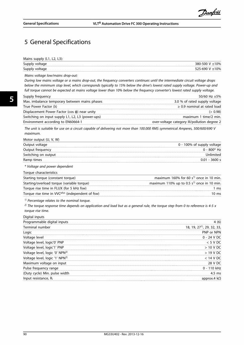
5 General Specifications
Mains supply (L1, L2, L3):Supply voltage 380-500 V ±10%Supply voltage 525-690 V ±10%
Mains voltage low/mains drop-out:During low mains voltage or a mains drop-out, the frequency converters continues until the intermediate circuit voltage dropsbelow the minimum stop level, which corresponds typically to 15% below the drive's lowest rated supply voltage. Power-up andfull torque cannot be expected at mains voltage lower than 10% below the frequency converter’s lowest rated supply voltage.
Supply frequency 50/60 Hz ±5%Max. imbalance temporary between mains phases 3.0 % of rated supply voltageTrue Power Factor (λ) ≥ 0.9 nominal at rated loadDisplacement Power Factor (cos ϕ) near unity (> 0.98)Switching on input supply L1, L2, L3 (power-ups) maximum 1 time/2 min.Environment according to EN60664-1 over-voltage category III/pollution degree 2
The unit is suitable for use on a circuit capable of delivering not more than 100.000 RMS symmetrical Amperes, 500/600/690 Vmaximum.
Motor output (U, V, W)Output voltage 0 - 100% of supply voltageOutput frequency 0 - 800* HzSwitching on output UnlimitedRamp times 0.01 - 3600 s
* Voltage and power dependent
Torque characteristicsStarting torque (constant torque) maximum 160% for 60 s1) once in 10 min.Starting/overload torque (variable torque) maximum 110% up to 0.5 s1) once in 10 min.Torque rise time in FLUX (for 5 kHz fsw) 1 msTorque rise time in VVCplus (independent of fsw) 10 ms
1) Percentage relates to the nominal torque.2) The torque response time depends on application and load but as a general rule, the torque step from 0 to reference is 4-5 xtorque rise time.
Digital inputsProgrammable digital inputs 4 (6)Terminal number 18, 19, 271), 29, 32, 33,Logic PNP or NPNVoltage level 0 - 24 V DCVoltage level, logic'0' PNP < 5 V DCVoltage level, logic'1' PNP > 10 V DCVoltage level, logic '0' NPN2) > 19 V DCVoltage level, logic '1' NPN2) < 14 V DCMaximum voltage on input 28 V DCPulse frequency range 0 - 110 kHz(Duty cycle) Min. pulse width 4.5 msInput resistance, Ri approx.4 kΩ
General Specifications VLT® Automation Drive FC 300 Operating Instructions
90 MG33U402 - Rev. 2013-12-16
55

Safe stop Terminal 373) (Terminal 37 is fixed PNP logic)Voltage level 0 - 24 V DCVoltage level, logic'0' PNP < 4 V DCVoltage level, logic'1' PNP >20 V DCNominal input current at 24 V 50 mA rmsNominal input current at 20 V 60 mA rmsInput capacitance 400 nF
All digital inputs are galvanically isolated from the supply voltage (PELV) and other high-voltage terminals.1) Terminals 27 and 29 can also be programmed as output.
2) Except safe stop input Terminal 37.3) See chapter 2.1.9 Safe Torque Off (STO) for further information about terminal 37 and Safe Stop..
Analog inputsNumber of analog inputs 2Terminal number 53, 54Modes Voltage or currentMode select Switch S201 and switch S202Voltage mode Switch S201/switch S202 = OFF (U)Voltage level -10 to +10 V (scaleable)Input resistance, Ri approx. 10 kΩMax. voltage ± 20 VCurrent mode Switch S201/switch S202 = ON (I)Current level 0/4 to 20 mA (scaleable)Input resistance, Ri approx. 200 ΩMax. current 30 mAResolution for analog inputs 10 bit (+ sign)Accuracy of analog inputs Max. error 0.5% of full scaleBandwidth 100 Hz
The analog inputs are galvanically isolated from the supply voltage (PELV) and other high-voltage terminals.
Mains
Functionalisolation
PELV isolation
Motor
DC-Bus
Highvoltage
Control+24V
RS485
18
37
130B
A11
7.10
Illustration 5.1
General Specifications VLT® Automation Drive FC 300 Operating Instructions
MG33U402 - Rev. 2013-12-16 91
5 5
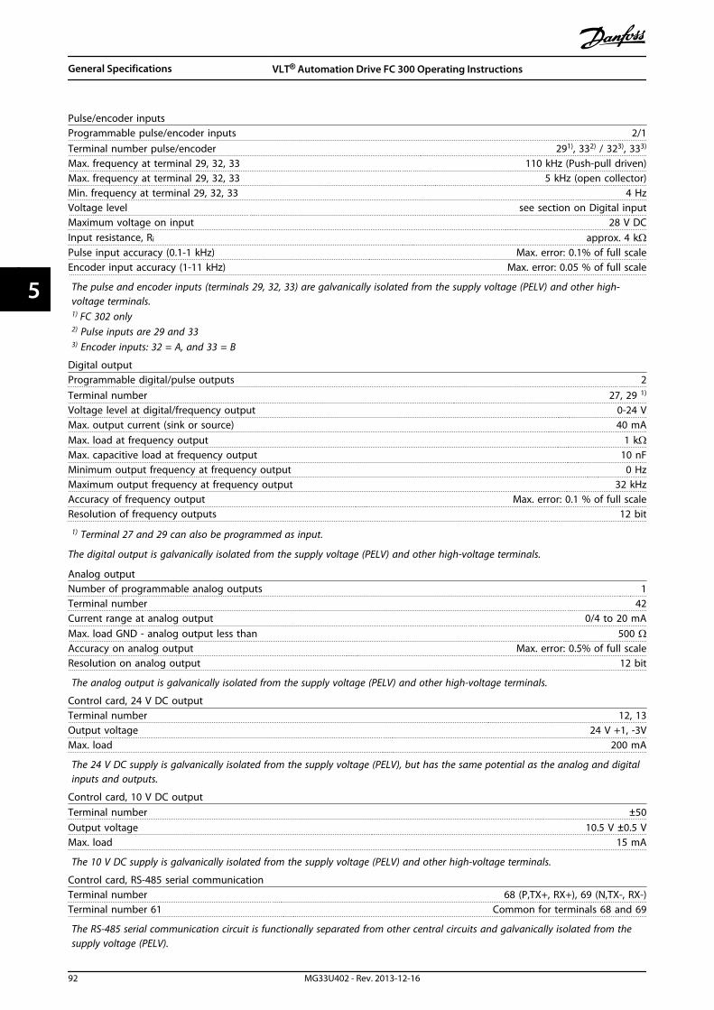
Pulse/encoder inputsProgrammable pulse/encoder inputs 2/1Terminal number pulse/encoder 291), 332) / 323), 333)
Max. frequency at terminal 29, 32, 33 110 kHz (Push-pull driven)Max. frequency at terminal 29, 32, 33 5 kHz (open collector)Min. frequency at terminal 29, 32, 33 4 HzVoltage level see section on Digital inputMaximum voltage on input 28 V DCInput resistance, Ri approx. 4 kΩPulse input accuracy (0.1-1 kHz) Max. error: 0.1% of full scaleEncoder input accuracy (1-11 kHz) Max. error: 0.05 % of full scale
The pulse and encoder inputs (terminals 29, 32, 33) are galvanically isolated from the supply voltage (PELV) and other high-voltage terminals.1) FC 302 only2) Pulse inputs are 29 and 333) Encoder inputs: 32 = A, and 33 = B
Digital outputProgrammable digital/pulse outputs 2Terminal number 27, 29 1)
Voltage level at digital/frequency output 0-24 VMax. output current (sink or source) 40 mAMax. load at frequency output 1 kΩMax. capacitive load at frequency output 10 nFMinimum output frequency at frequency output 0 HzMaximum output frequency at frequency output 32 kHzAccuracy of frequency output Max. error: 0.1 % of full scaleResolution of frequency outputs 12 bit
1) Terminal 27 and 29 can also be programmed as input.
The digital output is galvanically isolated from the supply voltage (PELV) and other high-voltage terminals.
Analog outputNumber of programmable analog outputs 1Terminal number 42Current range at analog output 0/4 to 20 mAMax. load GND - analog output less than 500 ΩAccuracy on analog output Max. error: 0.5% of full scaleResolution on analog output 12 bit
The analog output is galvanically isolated from the supply voltage (PELV) and other high-voltage terminals.
Control card, 24 V DC outputTerminal number 12, 13Output voltage 24 V +1, -3VMax. load 200 mA
The 24 V DC supply is galvanically isolated from the supply voltage (PELV), but has the same potential as the analog and digitalinputs and outputs.
Control card, 10 V DC outputTerminal number ±50Output voltage 10.5 V ±0.5 VMax. load 15 mA
The 10 V DC supply is galvanically isolated from the supply voltage (PELV) and other high-voltage terminals.
Control card, RS-485 serial communicationTerminal number 68 (P,TX+, RX+), 69 (N,TX-, RX-)Terminal number 61 Common for terminals 68 and 69
The RS-485 serial communication circuit is functionally separated from other central circuits and galvanically isolated from thesupply voltage (PELV).
General Specifications VLT® Automation Drive FC 300 Operating Instructions
92 MG33U402 - Rev. 2013-12-16
55

Control card, USB serial communication:USB standard 1.1 (Full speed)USB plug USB type B plug
Connection to PC is carried out via a standard host/device USB cable.The USB connection is galvanically isolated from the supply voltage (PELV) and other high-voltage terminals.The USB ground connection is not galvanically isolated from protection earth. Use only an isolated laptop as PC connection tothe USB connector on the frequency converter.
Relay outputsProgrammable relay outputs 2Relay 01 Terminal number 1-3 (break), 1-2 (make)Max. terminal load (AC-1)1) on 1-3 (NC), 1-2 (NO) (Resistive load) 240 V AC, 2 AMax. terminal load (AC-15)1) (Inductive load @ cosφ 0.4) 240 V AC, 0.2 AMax. terminal load (DC-1)1) on 1-2 (NO), 1-3 (NC) (Resistive load) 60 V DC, 1 AMax. terminal load (DC-13)1) (Inductive load) 24 V DC, 0.1 ARelay 02 (FC 302 only) Terminal number 4-6 (break), 4-5 (make)Max. terminal load (AC-1)1) on 4-5 (NO) (Resistive load) 400 V AC, 2 AMax. terminal load (AC-15)1) on 4-5 (NO) (Inductive load @ cosφ 0.4) 240 V AC, 0.2 AMax. terminal load (DC-1)1) on 4-5 (NO) (Resistive load) 80 V DC, 2 AMax. terminal load (DC-13)1) on 4-5 (NO) (Inductive load) 24 V DC, 0.1 AMax. terminal load (AC-1)1) on 4-6 (NC) (Resistive load) 240 V AC, 2 AMax. terminal load (AC-15)1) on 4-6 (NC) (Inductive load @ cosφ 0.4) 240 V AC, 0.2 AMax. terminal load (DC-1)1) on 4-6 (NC) (Resistive load) 50 V DC, 2 AMax. terminal load (DC-13)1) on 4-6 (NC) (Inductive load) 24 V DC, 0.1 AMin. terminal load on 1-3 (NC), 1-2 (NO), 4-6 (NC), 4-5 (NO) 24 V DC 10 mA, 24 V AC 20 mAEnvironment according to EN 60664-1 overvoltage category III/pollution degree 2
1) IEC 60947 part 4 and 5The relay contacts are galvanically isolated from the rest of the circuit by reinforced isolation (PELV).
Cable lengths and cross sectionsMax. motor cable length, screened/armoured 150 mMax. motor cable length, unscreened/unarmoured 300 mMaximum cross section to control terminals, flexible/ rigid wire without cable end sleeves 1.5 mm2/16 AWGMaximum cross section to control terminals, flexible wire with cable end sleeves 1 mm2/18 AWGMaximum cross section to control terminals, flexible wire with cable end sleeves with collar 0.5 mm2/20 AWGMinimum cross section to control terminals 0.25 mm2/24 AWG
Control card performanceScan interval 1 ms
Control characteristicsResolution of output frequency at 0-590 Hz ±0.003 HzRepeat accuracy of Precise start/stop (terminals 18, 19) ≤±0.1 msSystem response time (terminals 18, 19, 27, 29, 32, 33) ≤ 2 msSpeed control range (open loop) 1:100 of synchronous speedSpeed control range (closed loop) 1:1000 of synchronous speedSpeed accuracy (open loop) 30-4000 RPM: error ±8 RPMSpeed accuracy (closed loop), depending on resolution of feedback device 0-6000 RPM: error ±0.15 RPMTorque control accuracy (speed feedback) max error ±5% of rated torque
All control characteristics are based on a 4-pole asynchronous motor
General Specifications VLT® Automation Drive FC 300 Operating Instructions
MG33U402 - Rev. 2013-12-16 93
5 5
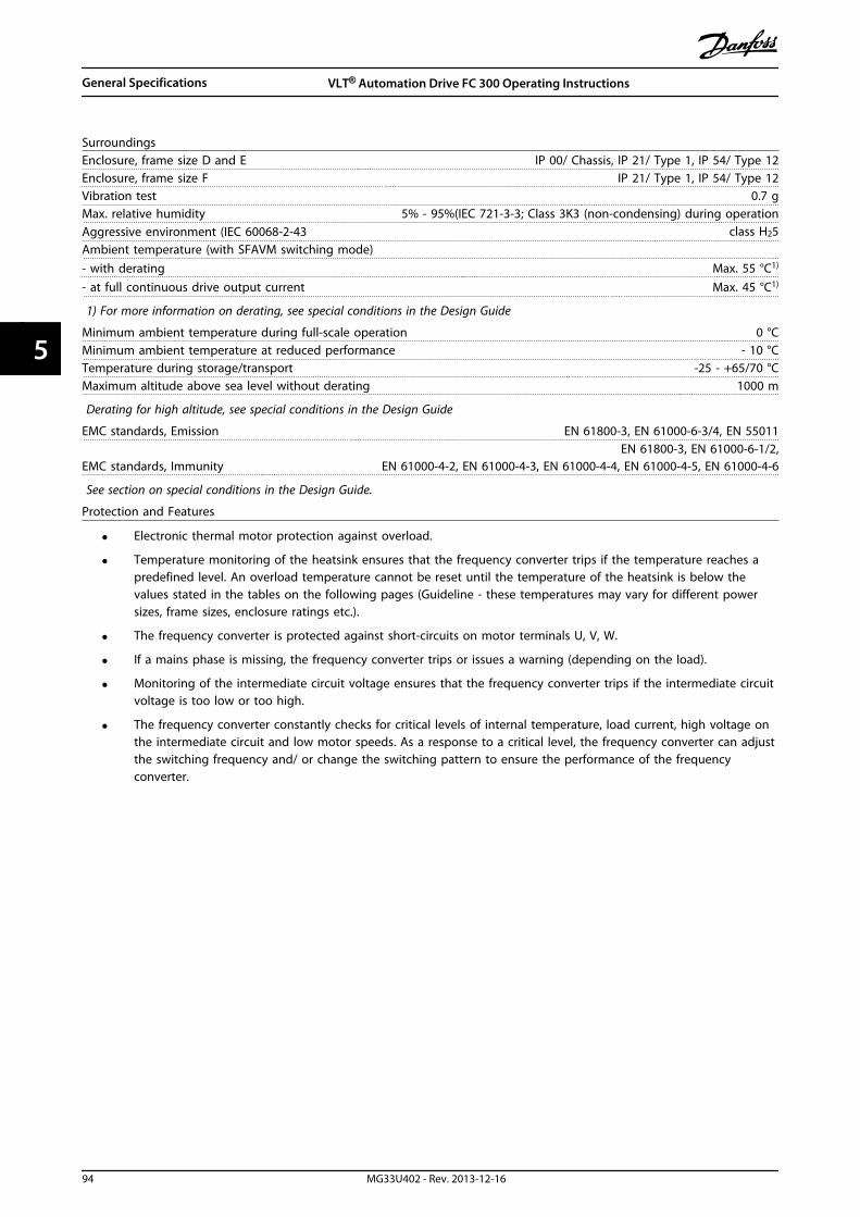
SurroundingsEnclosure, frame size D and E IP 00/ Chassis, IP 21/ Type 1, IP 54/ Type 12Enclosure, frame size F IP 21/ Type 1, IP 54/ Type 12Vibration test 0.7 gMax. relative humidity 5% - 95%(IEC 721-3-3; Class 3K3 (non-condensing) during operationAggressive environment (IEC 60068-2-43 class H25Ambient temperature (with SFAVM switching mode)- with derating Max. 55 °C1)
- at full continuous drive output current Max. 45 °C1)
1) For more information on derating, see special conditions in the Design Guide
Minimum ambient temperature during full-scale operation 0 °CMinimum ambient temperature at reduced performance - 10 °CTemperature during storage/transport -25 - +65/70 °CMaximum altitude above sea level without derating 1000 m
Derating for high altitude, see special conditions in the Design Guide
EMC standards, Emission EN 61800-3, EN 61000-6-3/4, EN 55011
EMC standards, ImmunityEN 61800-3, EN 61000-6-1/2,
EN 61000-4-2, EN 61000-4-3, EN 61000-4-4, EN 61000-4-5, EN 61000-4-6
See section on special conditions in the Design Guide.
Protection and Features
• Electronic thermal motor protection against overload.
• Temperature monitoring of the heatsink ensures that the frequency converter trips if the temperature reaches apredefined level. An overload temperature cannot be reset until the temperature of the heatsink is below thevalues stated in the tables on the following pages (Guideline - these temperatures may vary for different powersizes, frame sizes, enclosure ratings etc.).
• The frequency converter is protected against short-circuits on motor terminals U, V, W.
• If a mains phase is missing, the frequency converter trips or issues a warning (depending on the load).
• Monitoring of the intermediate circuit voltage ensures that the frequency converter trips if the intermediate circuitvoltage is too low or too high.
• The frequency converter constantly checks for critical levels of internal temperature, load current, high voltage onthe intermediate circuit and low motor speeds. As a response to a critical level, the frequency converter can adjustthe switching frequency and/ or change the switching pattern to ensure the performance of the frequencyconverter.
General Specifications VLT® Automation Drive FC 300 Operating Instructions
94 MG33U402 - Rev. 2013-12-16
55

Mains Supply 3 x 380 - 500 V AC
FC 302 P90K P110 P132 P160 P200
High/ Normal Load* HO NO HO NO HO NO HO NO HO NO
Typical Shaft output at400 V [kW]
90 110 110 132 132 160 160 200 200 250
Typical Shaft output at460 V [hp]
125 150 150 200 200 250 250 300 300 350
Typical Shaft output at500 V [kW]
110 132 132 160 160 200 200 250 250 315
Enclosure IP21 D1 D1 D2 D2 D2
Enclosure IP54 D1 D1 D2 D2 D2
Enclosure IP00 D3 D3 D4 D4 D4
Output current
Continuous(at 400 V) [A]
177 212 212 260 260 315 315 395 395 480
Intermittent (60 soverload)(at 400 V) [A]
266 233 318 286 390 347 473 435 593 528
Continuous(at 460/500 V) [A]
160 190 190 240 240 302 302 361 361 443
Intermittent (60 soverload)(at 460/500 V) [A]
240 209 285 264 360 332 453 397 542 487
Continuous kVA(at 400 V) [kVA]
123 147 147 180 180 218 218 274 274 333
Continuous kVA(at 460 V) [kVA]
127 151 151 191 191 241 241 288 288 353
Continuous kVA(at 500 V) [kVA]
139 165 165 208 208 262 262 313 313 384
Max. input current
Continuous(at 400 V) [A]
171 204 204 251 251 304 304 381 381 463
Continuous(at 460/500 V) [A]
154 183 183 231 231 291 291 348 348 427
Max. cable size, mainsmotor, brake and load
share [mm2 (AWG2))]
2 x 70(2 x 2/0)
2 x 70(2 x 2/0)
2 x 150(2 x 300 mcm)
2 x 150(2 x 300 mcm)
2 x 150(2 x 300 mcm)
Max. external mains fuses
[A] 1300 350 400 500 630
Estimated power loss
at 400 V [W] 4)2369 2907 2634 3357 3117 3914 3640 4812 4288 5517
Estimated power lossat 460 V [W]
2162 2599 2350 3078 2886 3781 3629 4535 3624 5025
Weight,enclosure IP21, IP54 [kg]
96 104 125 136 151
Weight,enclosure IP00 [kg]
82 91 112 123 138
Efficiency4) 0.98
Output frequency 0 - 800 Hz
Heatsink overtemp. trip 90 °C 110 °C 110 °C 110 °C 110 °C
Power card ambient trip 75 °C
* High overload = 160% torque during 60 s, Normal overload = 110% torque during 60 s
Table 5.1
General Specifications VLT® Automation Drive FC 300 Operating Instructions
MG33U402 - Rev. 2013-12-16 95
5 5

Mains Supply 3 x 380 - 500 V AC
FC 302 P250 P315 P355 P400
High/ Normal Load* HO NO HO NO HO NO HO NO
Typical Shaft output at 400 V[kW]
250 315 315 355 355 400 400 450
Typical Shaft output at 460 V[hp]
350 450 450 500 500 600 550 600
Typical Shaft output at 500 V[kW]
315 355 355 400 400 500 500 530
Enclosure IP21 E1 E1 E1 E1
Enclosure IP54 E1 E1 E1 E1
Enclosure IP00 E2 E2 E2 E2
Output current
Continuous(at 400 V) [A]
480 600 600 658 658 745 695 800
Intermittent (60 sec overload)(at 400 V) [A]
720 660 900 724 987 820 1043 880
Continuous(at 460/500 V) [A]
443 540 540 590 590 678 678 730
Intermittent (60 s overload)(at 460/500 V) [A]
665 594 810 649 885 746 1017 803
Continuous kVA(at 400 V) [kVA]
333 416 416 456 456 516 482 554
Continuous kVA(at 460 V) [kVA]
353 430 430 470 470 540 540 582
Continuous kVA(at 500 V) [kVA]
384 468 468 511 511 587 587 632
Max. input current
Continuous(at 400 V ) [A]
472 590 590 647 647 733 684 787
Continuous(at 460/500 V) [A]
436 531 531 580 580 667 667 718
Max. cable size, mains, motor
and load share [mm2 (AWG2))]
4x240(4x500 mcm)
4x240(4x500 mcm)
4x240(4x500 mcm)
4x240(4x500 mcm)
Max. cable size, brake [mm2
(AWG2))
2 x 185(2 x 350 mcm)
2 x 185(2 x 350 mcm)
2 x 185(2 x 350 mcm)
2 x 185(2 x 350 mcm)
Max. external mains fuses [A] 1 700 900 900 900
Estimated power loss
at 400 V [W] 4)5059 6705 6794 7532 7498 8677 7976 9473
Estimated power lossat 460 V [W]
4822 6082 6345 6953 6944 8089 8085 7814
Weight,enclosure IP21, IP54 [kg]
263 270 272 313
Weight,enclosure IP00 [kg]
221 234 236 277
Efficiency4) 0.98
Output frequency 0 - 600 Hz
Heatsink overtemp. trip 110 °C
Power card ambient trip 75 °C
* High overload = 160% torque during 60 s, Normal overload = 110% torque during 60 s
Table 5.2
General Specifications VLT® Automation Drive FC 300 Operating Instructions
96 MG33U402 - Rev. 2013-12-16
55
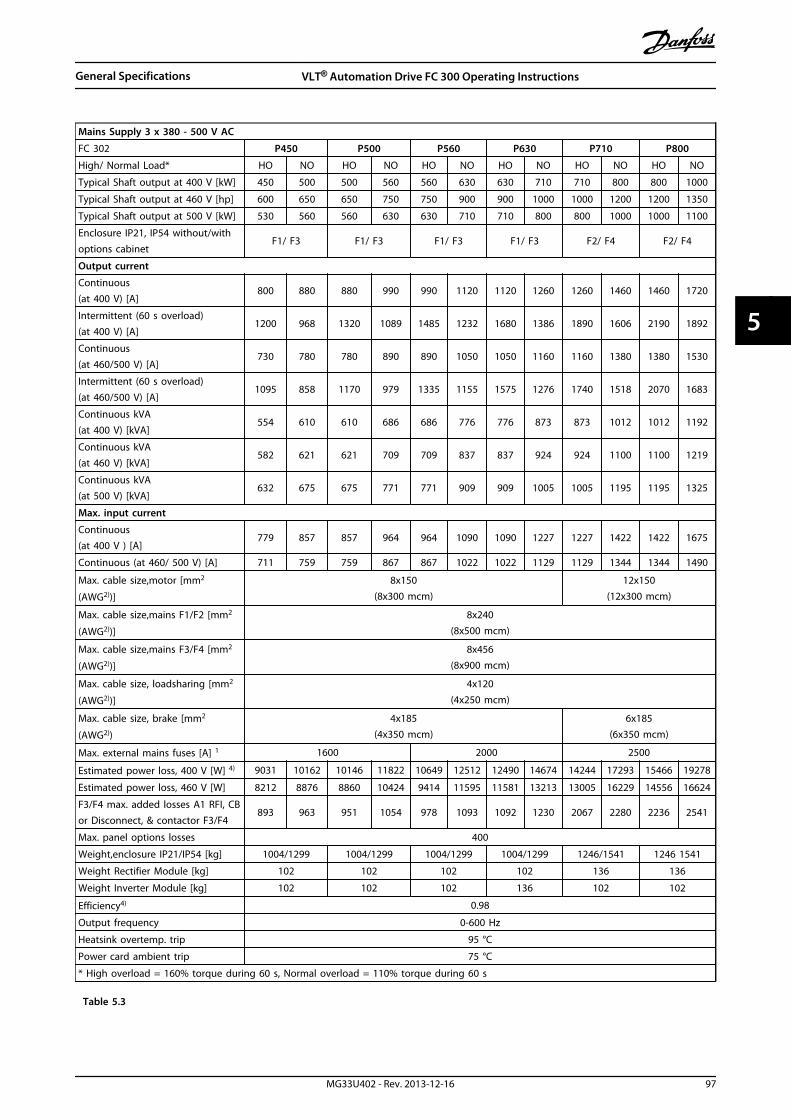
Mains Supply 3 x 380 - 500 V AC
FC 302 P450 P500 P560 P630 P710 P800
High/ Normal Load* HO NO HO NO HO NO HO NO HO NO HO NO
Typical Shaft output at 400 V [kW] 450 500 500 560 560 630 630 710 710 800 800 1000
Typical Shaft output at 460 V [hp] 600 650 650 750 750 900 900 1000 1000 1200 1200 1350
Typical Shaft output at 500 V [kW] 530 560 560 630 630 710 710 800 800 1000 1000 1100
Enclosure IP21, IP54 without/withoptions cabinet
F1/ F3 F1/ F3 F1/ F3 F1/ F3 F2/ F4 F2/ F4
Output current
Continuous(at 400 V) [A]
800 880 880 990 990 1120 1120 1260 1260 1460 1460 1720
Intermittent (60 s overload)(at 400 V) [A]
1200 968 1320 1089 1485 1232 1680 1386 1890 1606 2190 1892
Continuous(at 460/500 V) [A]
730 780 780 890 890 1050 1050 1160 1160 1380 1380 1530
Intermittent (60 s overload)(at 460/500 V) [A]
1095 858 1170 979 1335 1155 1575 1276 1740 1518 2070 1683
Continuous kVA(at 400 V) [kVA]
554 610 610 686 686 776 776 873 873 1012 1012 1192
Continuous kVA(at 460 V) [kVA]
582 621 621 709 709 837 837 924 924 1100 1100 1219
Continuous kVA(at 500 V) [kVA]
632 675 675 771 771 909 909 1005 1005 1195 1195 1325
Max. input current
Continuous(at 400 V ) [A]
779 857 857 964 964 1090 1090 1227 1227 1422 1422 1675
Continuous (at 460/ 500 V) [A] 711 759 759 867 867 1022 1022 1129 1129 1344 1344 1490
Max. cable size,motor [mm2
(AWG2))]
8x150(8x300 mcm)
12x150(12x300 mcm)
Max. cable size,mains F1/F2 [mm2
(AWG2))]
8x240(8x500 mcm)
Max. cable size,mains F3/F4 [mm2
(AWG2))]
8x456(8x900 mcm)
Max. cable size, loadsharing [mm2
(AWG2))]
4x120(4x250 mcm)
Max. cable size, brake [mm2
(AWG2))
4x185(4x350 mcm)
6x185(6x350 mcm)
Max. external mains fuses [A] 1 1600 2000 2500
Estimated power loss, 400 V [W] 4) 9031 10162 10146 11822 10649 12512 12490 14674 14244 17293 15466 19278
Estimated power loss, 460 V [W] 8212 8876 8860 10424 9414 11595 11581 13213 13005 16229 14556 16624
F3/F4 max. added losses A1 RFI, CBor Disconnect, & contactor F3/F4
893 963 951 1054 978 1093 1092 1230 2067 2280 2236 2541
Max. panel options losses 400
Weight,enclosure IP21/IP54 [kg] 1004/1299 1004/1299 1004/1299 1004/1299 1246/1541 1246 1541
Weight Rectifier Module [kg] 102 102 102 102 136 136
Weight Inverter Module [kg] 102 102 102 136 102 102
Efficiency4) 0.98
Output frequency 0-600 Hz
Heatsink overtemp. trip 95 °C
Power card ambient trip 75 °C
* High overload = 160% torque during 60 s, Normal overload = 110% torque during 60 s
Table 5.3
General Specifications VLT® Automation Drive FC 300 Operating Instructions
MG33U402 - Rev. 2013-12-16 97
5 5
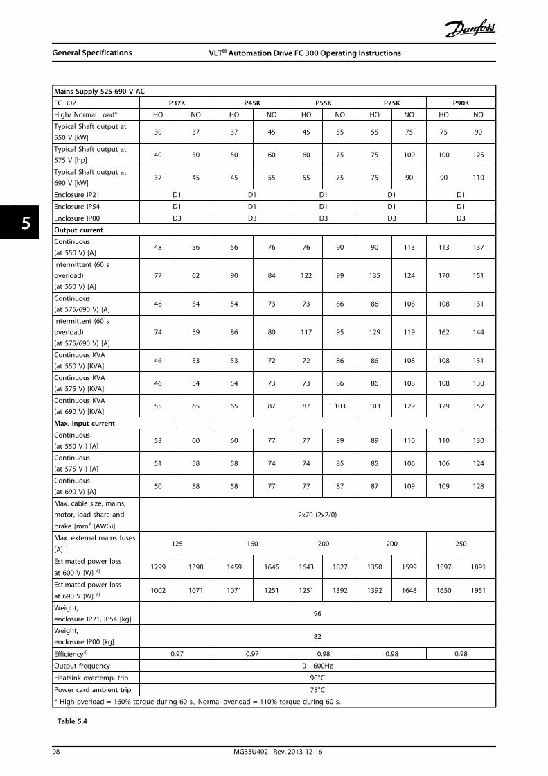
Mains Supply 525-690 V AC
FC 302 P37K P45K P55K P75K P90K
High/ Normal Load* HO NO HO NO HO NO HO NO HO NO
Typical Shaft output at550 V [kW]
30 37 37 45 45 55 55 75 75 90
Typical Shaft output at575 V [hp]
40 50 50 60 60 75 75 100 100 125
Typical Shaft output at690 V [kW]
37 45 45 55 55 75 75 90 90 110
Enclosure IP21 D1 D1 D1 D1 D1
Enclosure IP54 D1 D1 D1 D1 D1
Enclosure IP00 D3 D3 D3 D3 D3
Output current
Continuous(at 550 V) [A]
48 56 56 76 76 90 90 113 113 137
Intermittent (60 soverload)(at 550 V) [A]
77 62 90 84 122 99 135 124 170 151
Continuous(at 575/690 V) [A]
46 54 54 73 73 86 86 108 108 131
Intermittent (60 soverload)(at 575/690 V) [A]
74 59 86 80 117 95 129 119 162 144
Continuous KVA(at 550 V) [KVA]
46 53 53 72 72 86 86 108 108 131
Continuous KVA(at 575 V) [KVA]
46 54 54 73 73 86 86 108 108 130
Continuous KVA(at 690 V) [KVA]
55 65 65 87 87 103 103 129 129 157
Max. input current
Continuous(at 550 V ) [A]
53 60 60 77 77 89 89 110 110 130
Continuous(at 575 V ) [A]
51 58 58 74 74 85 85 106 106 124
Continuous(at 690 V) [A]
50 58 58 77 77 87 87 109 109 128
Max. cable size, mains,motor, load share and
brake [mm2 (AWG)]
2x70 (2x2/0)
Max. external mains fuses
[A] 1125 160 200 200 250
Estimated power loss
at 600 V [W] 4)1299 1398 1459 1645 1643 1827 1350 1599 1597 1891
Estimated power loss
at 690 V [W] 4)1002 1071 1071 1251 1251 1392 1392 1648 1650 1951
Weight,enclosure IP21, IP54 [kg]
96
Weight,enclosure IP00 [kg]
82
Efficiency4) 0.97 0.97 0.98 0.98 0.98
Output frequency 0 - 600Hz
Heatsink overtemp. trip 90°C
Power card ambient trip 75°C
* High overload = 160% torque during 60 s., Normal overload = 110% torque during 60 s.
Table 5.4
General Specifications VLT® Automation Drive FC 300 Operating Instructions
98 MG33U402 - Rev. 2013-12-16
55

Mains Supply 525-690 V AC
FC 302 P110 P132 P160 P200
High/ Normal Load* HO NO HO NO HO NO HO NO
Typical Shaft output at 550 V[kW]
90 110 110 132 132 160 160 200
Typical Shaft output at 575 V[hp]
125 150 150 200 200 250 250 300
Typical Shaft output at 690 V[kW]
110 132 132 160 160 200 200 250
Enclosure IP21 D1 D1 D2 D2
Enclosure IP54 D1 D1 D2 D2
Enclosure IP00 D3 D3 D4 D4
Output current
Continuous(at 550 V) [A]
137 162 162 201 201 253 253 303
Intermittent (60 s overload)(at 550 V) [A]
206 178 243 221 302 278 380 333
Continuous(at 575/690 V) [A]
131 155 155 192 192 242 242 290
Intermittent (60 s overload)(at 575/690 V) [A]
197 171 233 211 288 266 363 319
Continuous KVA(at 550 V) [KVA]
131 154 154 191 191 241 241 289
Continuous KVA(at 575 V) [KVA]
130 154 154 191 191 241 241 289
Continuous KVA(at 690 V) [KVA]
157 185 185 229 229 289 289 347
Max. input current
Continuous(at 550 V) [A]
130 158 158 198 198 245 245 299
Continuous(at 575 V) [A]
124 151 151 189 189 234 234 286
Continuous(at 690 V) [A]
128 155 155 197 197 240 240 296
Max. cable size, mains motor,
load share and brake [mm2
(AWG)]
2 x 70 (2 x 2/0) 2 x 70 (2 x 2/0) 2 x 150 (2 x 300 mcm) 2 x 150 (2 x 300 mcm)
Max. external mains fuses [A] 1 315 350 350 400
Estimated power loss
at 600 V [W] 4)1890 2230 2101 2617 2491 3197 3063 3757
Estimated power loss
at 690 V [W] 4)1953 2303 2185 2707 2606 3320 3192 3899
Weight,Enclosure IP21, IP54 [kg]
96 104 125 136
Weight,Enclosure IP00 [kg]
82 91 112 123
Efficiency4) 0.98
Output frequency 0 - 600 Hz
Heatsink overtemp. trip 90°C 110°C 110°C 110°C
Power card ambient trip 75°C
* High overload = 160% torque during 60 s., Normal overload = 110% torque during 60 s.
Table 5.5
General Specifications VLT® Automation Drive FC 300 Operating Instructions
MG33U402 - Rev. 2013-12-16 99
5 5
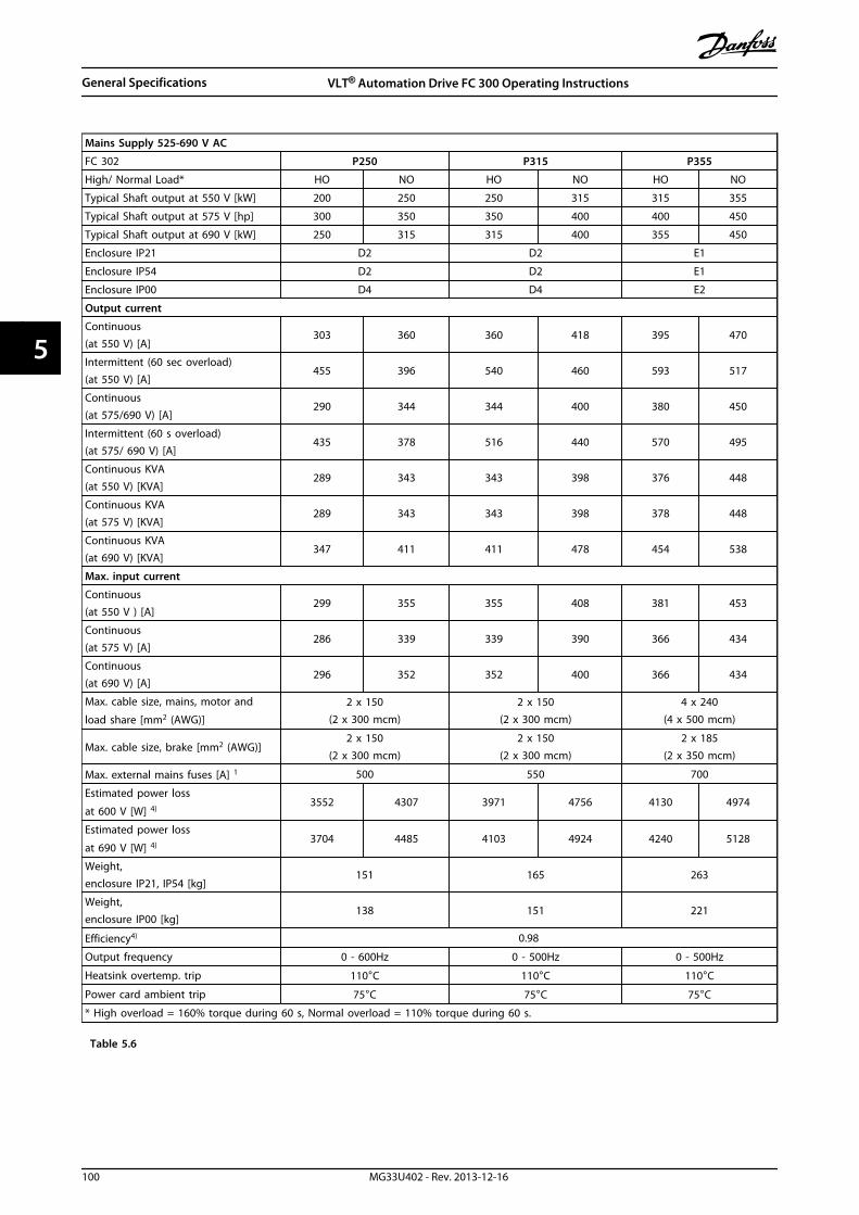
Mains Supply 525-690 V AC
FC 302 P250 P315 P355
High/ Normal Load* HO NO HO NO HO NO
Typical Shaft output at 550 V [kW] 200 250 250 315 315 355
Typical Shaft output at 575 V [hp] 300 350 350 400 400 450
Typical Shaft output at 690 V [kW] 250 315 315 400 355 450
Enclosure IP21 D2 D2 E1
Enclosure IP54 D2 D2 E1
Enclosure IP00 D4 D4 E2
Output current
Continuous(at 550 V) [A]
303 360 360 418 395 470
Intermittent (60 sec overload)(at 550 V) [A]
455 396 540 460 593 517
Continuous(at 575/690 V) [A]
290 344 344 400 380 450
Intermittent (60 s overload)(at 575/ 690 V) [A]
435 378 516 440 570 495
Continuous KVA(at 550 V) [KVA]
289 343 343 398 376 448
Continuous KVA(at 575 V) [KVA]
289 343 343 398 378 448
Continuous KVA(at 690 V) [KVA]
347 411 411 478 454 538
Max. input current
Continuous(at 550 V ) [A]
299 355 355 408 381 453
Continuous(at 575 V) [A]
286 339 339 390 366 434
Continuous(at 690 V) [A]
296 352 352 400 366 434
Max. cable size, mains, motor and
load share [mm2 (AWG)]
2 x 150(2 x 300 mcm)
2 x 150(2 x 300 mcm)
4 x 240(4 x 500 mcm)
Max. cable size, brake [mm2 (AWG)]2 x 150
(2 x 300 mcm)2 x 150
(2 x 300 mcm)2 x 185
(2 x 350 mcm)
Max. external mains fuses [A] 1 500 550 700
Estimated power loss
at 600 V [W] 4)3552 4307 3971 4756 4130 4974
Estimated power loss
at 690 V [W] 4)3704 4485 4103 4924 4240 5128
Weight,enclosure IP21, IP54 [kg]
151 165 263
Weight,enclosure IP00 [kg]
138 151 221
Efficiency4) 0.98
Output frequency 0 - 600Hz 0 - 500Hz 0 - 500Hz
Heatsink overtemp. trip 110°C 110°C 110°C
Power card ambient trip 75°C 75°C 75°C
* High overload = 160% torque during 60 s, Normal overload = 110% torque during 60 s.
Table 5.6
General Specifications VLT® Automation Drive FC 300 Operating Instructions
100 MG33U402 - Rev. 2013-12-16
55

Mains Supply 525-690 V AC
FC 302 P400 P500 P560
High/ Normal Load* HO NO HO NO HO NO
Typical Shaft output at 550 V [kW] 315 400 400 450 450 500
Typical Shaft output at 575 V [hp] 400 500 500 600 600 650
Typical Shaft output at 690 V [kW] 400 500 500 560 560 630
Enclosure IP21 E1 E1 E1
Enclosure IP54 E1 E1 E1
Enclosure IP00 E2 E2 E2
Output current
Continuous(at 550 V) [A]
429 523 523 596 596 630
Intermittent (60 sec overload)(at 550 V) [A]
644 575 785 656 894 693
Continuous(at 575/690 V) [A]
410 500 500 570 570 630
Intermittent (60 s overload)(at 575/690 V) [A]
615 550 750 627 855 693
Continuous KVA(at 550 V) [KVA]
409 498 498 568 568 600
Continuous KVA(at 575 V) [KVA]
408 498 498 568 568 627
Continuous KVA(at 690 V) [KVA]
490 598 598 681 681 753
Max. input current
Continuous(at 550 V ) [A]
413 504 504 574 574 607
Continuous(at 575 V) [A]
395 482 482 549 549 607
Continuous(at 690 V) [A]
395 482 482 549 549 607
Max. cable size, mains, motor and
load share [mm2 (AWG)]4x240 (4x500 mcm) 4x240 (4x500 mcm) 4x240 (4x500 mcm)
Max. cable size, brake [mm2 (AWG)]2 x 185
(2 x 350 mcm)2 x 185
(2 x 350 mcm)2 x 185
(2 x 350 mcm)
Max. external mains fuses [A] 1 700 900 900
Estimated power loss
at 600 V [W] 4)4478 5623 6153 7018 7007 7793
Estimated power loss
at 690 V [W] 4)4605 5794 6328 7221 7201 8017
Weight,enclosure IP21, IP54 [kg]
263 272 313
Weight,enclosure IP00 [kg]
221 236 277
Efficiency4) 0.98
Output frequency 0 - 500Hz
Heatsink overtemp. trip 110°C
Power card ambient trip 75°C
* High overload = 160% torque during 60 s., Normal overload = 110% torque during 60 s.
Table 5.7
General Specifications VLT® Automation Drive FC 300 Operating Instructions
MG33U402 - Rev. 2013-12-16 101
5 5

Mains Supply 525-690 V AC
FC 302 P630 P710 P800
High/ Normal Load* HO NO HO NO HO NO
Typical Shaft output at 550 V [kW] 500 560 560 670 670 750
Typical Shaft output at 575 V [hp] 650 750 750 950 950 1050
Typical Shaft output at 690 V [kW] 630 710 710 800 800 900
Enclosure IP21, 54 without/ with optionscabinet
F1/ F3 F1/ F3 F1/ F3
Output current
Continuous(at 550 V) [A]
659 763 763 889 889 988
Intermittent (60 sec overload)(at 550 V) [A]
989 839 1145 978 1334 1087
Continuous(at 575/690 V) [A]
630 730 730 850 850 945
Intermittent (60 sec overload)(at 575/690 V) [A]
945 803 1095 935 1275 1040
Continuous KVA(at 550 V) [KVA]
628 727 727 847 847 941
Continuous KVA(at 575 V) [KVA]
627 727 727 847 847 941
Continuous KVA(at 690 V) [KVA]
753 872 872 1016 1016 1129
Max. input current
Continuous(at 550 V ) [A]
642 743 743 866 866 962
Continuous(at 575 V) [A]
613 711 711 828 828 920
Continuous(at 690 V) [A]
613 711 711 828 828 920
Max. cable size, motor [mm2 (AWG2))]8x150
(8x300 mcm)
Max. cable size,mains F1 [mm2 (AWG2))]8x240
(8x500 mcm)
Max. cable size,mains F3 [mm2 (AWG2))]8x456
(8x900 mcm)
Max. cable size, loadsharing [mm2
(AWG2))]
4x120(4x250 mcm)
Max. cable size, brake [mm2 (AWG2))4x185
(4x350 mcm)
Max. external mains fuses [A] 1 1600
Estimated power loss, 600 V [W] 4) 7586 8933 8683 10310 10298 11692
Estimated power loss, 690 V [W] 4) 7826 9212 8983 10659 10646 12080
F3/F4 Max added losses CB or Disconnect& Contactor
342 427 419 532 519 615
Max panel options losses 400
Weight,enclosure IP21, IP54 [kg]
1004/ 1299 1004/ 1299 1004/ 1299
Weight, Rectifier Module [kg] 102 102 102
Weight, Inverter Module [kg] 102 102 136
Efficiency4) 0.98
Output frequency 0-500 Hz
Heatsink overtemp. trip 95 °C 105 °C 95 °C
Power card ambient trip 75 °C
* High overload = 160% torque during 60 s., Normal overload = 110% torque during 60 s.
Table 5.8
General Specifications VLT® Automation Drive FC 300 Operating Instructions
102 MG33U402 - Rev. 2013-12-16
55

Mains Supply 525-690 V AC
FC 302 P900 P1M0 P1M2
High/ Normal Load* HO NO HO NO HO NO
Typical Shaft output at 550 V [kW] 750 850 850 1000 1000 1100
Typical Shaft output at 575 V [hp] 1050 1150 1150 1350 1350 1550
Typical Shaft output at 690 V [kW] 900 1000 1000 1200 1200 1400
Enclosure IP21, IP54 without/with optionscabinet
F2/ F4 F2/ F4 F2/ F4
Output current
Continuous(at 550 V) [A]
988 1108 1108 1317 1317 1479
Intermittent (60 s overload)(at 550 V) [A]
1482 1219 1662 1449 1976 1627
Continuous(at 575/690 V) [A]
945 1060 1060 1260 1260 1415
Intermittent (60 s overload)(at 575/690 V) [A]
1418 1166 1590 1386 1890 1557
Continuous KVA(at 550 V) [KVA]
941 1056 1056 1255 1255 1409
Continuous KVA(at 575 V) [KVA]
941 1056 1056 1255 1255 1409
Continuous KVA(at 690 V) [KVA]
1129 1267 1267 1506 1506 1691
Max. input current
Continuous(at 550 V ) [A]
962 1079 1079 1282 1282 1440
Continuous(at 575 V) [A]
920 1032 1032 1227 1227 1378
Continuous(at 690 V) [A]
920 1032 1032 1227 1227 1378
Max. cable size, motor [mm2 (AWG2))]12x150
(12x300 mcm)
Max. cable size,mains F2 [mm2 (AWG2))]8x240
(8x500 mcm)
Max. cable size,mains F4 [mm2 (AWG2))]8x456
(8x900 mcm)
Max. cable size, loadsharing [mm2 (AWG2))]4x120
(4x250 mcm)
Max. cable size, brake [mm2 (AWG2))6x185
(6x350 mcm)
Max. external mains fuses [A] 1 1600 2000 2500
Estimated power loss, 600V [W] 4) 11329 12909 12570 15358 15258 17602
Estimated power loss, 690V [W] 4) 11681 13305 12997 15865 15763 18173
F3/F4 Max added losses CB or Disconnect& Contactor
556 665 634 863 861 1044
Max panel options losses 400
Weight,enclosure IP21, IP54 [kg]
1246/ 1541 1246/ 1541 1280/1575
Weight, Rectifier Module [kg] 136 136 136
Weight, Inverter Module [kg] 102 102 136
Efficiency4) 0.98
Output frequency 0-500Hz
Heatsink overtemp. trip 105°C 105°C 95°C
Power card ambient trip 75°C
* High overload = 160% torque during 60 s., Normal overload = 110% torque during 60 s.
Table 5.9
General Specifications VLT® Automation Drive FC 300 Operating Instructions
MG33U402 - Rev. 2013-12-16 103
5 5

1) For type of fuse see chapter 3.5.13 Fuses.
2) American Wire Gauge.
3) Measured using 5 m screened motor cables at rated load and rated frequency.
4) The typical power loss is at nominal load conditions and expected to be within +/-15% (tolerence relates tovariety in voltage and cable conditions).Values are based on a typical motor efficiency (eff2/eff3 border line). Motors with lower efficiency will also add tothe power loss in the frequency converter and opposite.If the switching frequency is increased compared to the default setting, the power losses may rise significantly.LCP and typical control card power consumptions are included. Further options and customer load may add up to30 W to the losses. (Though typical only 4 W extra for a fully loaded control card, or options for slot A or slot B,each).Although measurements are made with state of the art equipment, some measurement inaccuracy must beallowed for (+/-5%).
General Specifications VLT® Automation Drive FC 300 Operating Instructions
104 MG33U402 - Rev. 2013-12-16
55

6 Warnings and Alarms
6.1 Status Messages
6.1.1 Warnings/Alarm Messages
A warning or an alarm is signalled by the relevant LED onthe front of the frequency converter and indicated by acode on the display.
A warning remains active until its cause is no longerpresent. Under certain circumstances operation of themotor may still be continued. Warning messages may becritical, but are not necessarily so.
An alarm trips the frequency converter. Reset alarms torestart operation once their cause has been rectified.
This may be done in three ways• By pressing [Reset].
• Via a digital input with the “Reset” function.
• Via serial communication/optional fieldbus.
NOTICEAfter a manual reset pressing [Reset], [Auto On] must bepressed to restart the motor.
If an alarm cannot be reset, the reason may be that itscause has not been rectified, or the alarm is trip-locked(see also Table 6.1).
Alarms that are trip-locked offer additional protection,meaning that the mains supply must be switched offbefore the alarm can be reset. After being switched backon, the frequency converter is no longer blocked and maybe reset as described above once the cause has beenrectified.
Alarms that are not trip-locked can also be reset using theautomatic reset function in 14-20 Reset Mode (Warning:automatic wake-up is possible!)
If a warning and alarm is marked against a code inTable 6.1, this means that either a warning occurs beforean alarm, or else that it is possible to specify whether it isa warning or an alarm that is to be displayed for a givenfault.
This is possible, for instance, in 1-90 Motor ThermalProtection. After an alarm or trip, the motor carries oncoasting, and the alarm and warning flash. Once theproblem has been rectified, only the alarm continuesflashing until the frequency converter is reset.
NOTICENo missing motor phase detection (no 30-32) and nostall detection is active when 1-10 Motor Construction isset to [1] PM non salient SPM.
No. Description Warning Alarm/Trip Alarm/Trip Lock ParameterReference
1 10 Volts low X
2 Live zero error (X) (X) 6-01 Live Zero TimeoutFunction
3 No motor (X) 1-80 Function at Stop
4 Mains phase loss (X) (X) (X) 14-12 Function atMains Imbalance
5 DC link voltage high X
6 DC link voltage low X
7 DC over-voltage X X
8 DC under voltage X X
9 Inverter overloaded X X
10 Motor ETR over temperature (X) (X) 1-90 Motor ThermalProtection
11 Motor thermistor over temperature (X) (X) 1-90 Motor ThermalProtection
12 Torque limit X X
13 Over Current X X X
Warnings and Alarms VLT® Automation Drive FC 300 Operating Instructions
MG33U402 - Rev. 2013-12-16 105
6 6

No. Description Warning Alarm/Trip Alarm/Trip Lock ParameterReference
14 Earth Fault X X X
15 Hardware mismatch X X
16 Short Circuit X X
17 Control word time-out (X) (X) 8-04 Control WordTimeout Function
18 Start Failed X 1-77 Compressor StartMax Speed [RPM] and1-79 Compressor Start
Max Time to Trip
20 Temp. Input Error
21 Param Error
22 Hoist Mech. Brake (X) (X) Parameter group 2-2*
23 Internal Fans X
24 External Fans X
25 Brake resistor short-circuited X
26 Brake resistor power limit (X) (X) 2-13 Brake PowerMonitoring
27 Brake chopper short-circuited X X
28 Brake check (X) (X) 2-15 Brake Check
29 Heatsink temp X X X
30 Motor phase U missing (X) (X) (X) 4-58 Missing MotorPhase Function
31 Motor phase V missing (X) (X) (X) 4-58 Missing MotorPhase Function
32 Motor phase W missing (X) (X) (X) 4-58 Missing MotorPhase Function
33 Inrush Fault X X
34 Fieldbus communication fault X X
35 Option Fault
36 Mains failure X X
37 Phase imbalance X
38 Internal Fault X X
39 Heatsink sensor X X
40 Overload of Digital Output Terminal 27 (X) 5-00 Digital I/O Mode,5-01 Terminal 27 Mode
41 Overload of Digital Output Terminal 29 (X) 5-00 Digital I/O Mode,5-02 Terminal 29 Mode
42 Ovrld X30/6-7 (X)
43 Ext. Supply (option)
45 Earth Fault 2 X X X
46 Pwr. card supply X X
47 24 V supply low X X X
48 1.8 V supply low X X
49 Speed limit X 1-86 Trip Speed Low[RPM]
50 AMA calibration failed X
51 AMA check Unom and Inom X
52 AMA low Inom X
53 AMA motor too big X
54 AMA motor too small X
55 AMA parameter out of range X
56 AMA interrupted by user X
Warnings and Alarms VLT® Automation Drive FC 300 Operating Instructions
106 MG33U402 - Rev. 2013-12-16
66
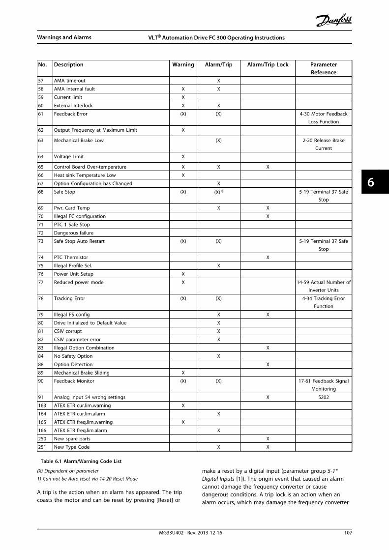
No. Description Warning Alarm/Trip Alarm/Trip Lock ParameterReference
57 AMA time-out X
58 AMA internal fault X X
59 Current limit X
60 External Interlock X X
61 Feedback Error (X) (X) 4-30 Motor FeedbackLoss Function
62 Output Frequency at Maximum Limit X
63 Mechanical Brake Low (X) 2-20 Release BrakeCurrent
64 Voltage Limit X
65 Control Board Over-temperature X X X
66 Heat sink Temperature Low X
67 Option Configuration has Changed X
68 Safe Stop (X) (X)1) 5-19 Terminal 37 SafeStop
69 Pwr. Card Temp X X
70 Illegal FC configuration X
71 PTC 1 Safe Stop
72 Dangerous failure
73 Safe Stop Auto Restart (X) (X) 5-19 Terminal 37 SafeStop
74 PTC Thermistor X
75 Illegal Profile Sel. X
76 Power Unit Setup X
77 Reduced power mode X 14-59 Actual Number ofInverter Units
78 Tracking Error (X) (X) 4-34 Tracking ErrorFunction
79 Illegal PS config X X
80 Drive Initialized to Default Value X
81 CSIV corrupt X
82 CSIV parameter error X
83 Illegal Option Combination X
84 No Safety Option X
88 Option Detection X
89 Mechanical Brake Sliding X
90 Feedback Monitor (X) (X) 17-61 Feedback SignalMonitoring
91 Analog input 54 wrong settings X S202
163 ATEX ETR cur.lim.warning X
164 ATEX ETR cur.lim.alarm X
165 ATEX ETR freq.lim.warning X
166 ATEX ETR freq.lim.alarm X
250 New spare parts X
251 New Type Code X X
Table 6.1 Alarm/Warning Code List
(X) Dependent on parameter1) Can not be Auto reset via 14-20 Reset Mode
A trip is the action when an alarm has appeared. The tripcoasts the motor and can be reset by pressing [Reset] or
make a reset by a digital input (parameter group 5-1*Digital Inputs [1]). The origin event that caused an alarmcannot damage the frequency converter or causedangerous conditions. A trip lock is an action when analarm occurs, which may damage the frequency converter
Warnings and Alarms VLT® Automation Drive FC 300 Operating Instructions
MG33U402 - Rev. 2013-12-16 107
6 6
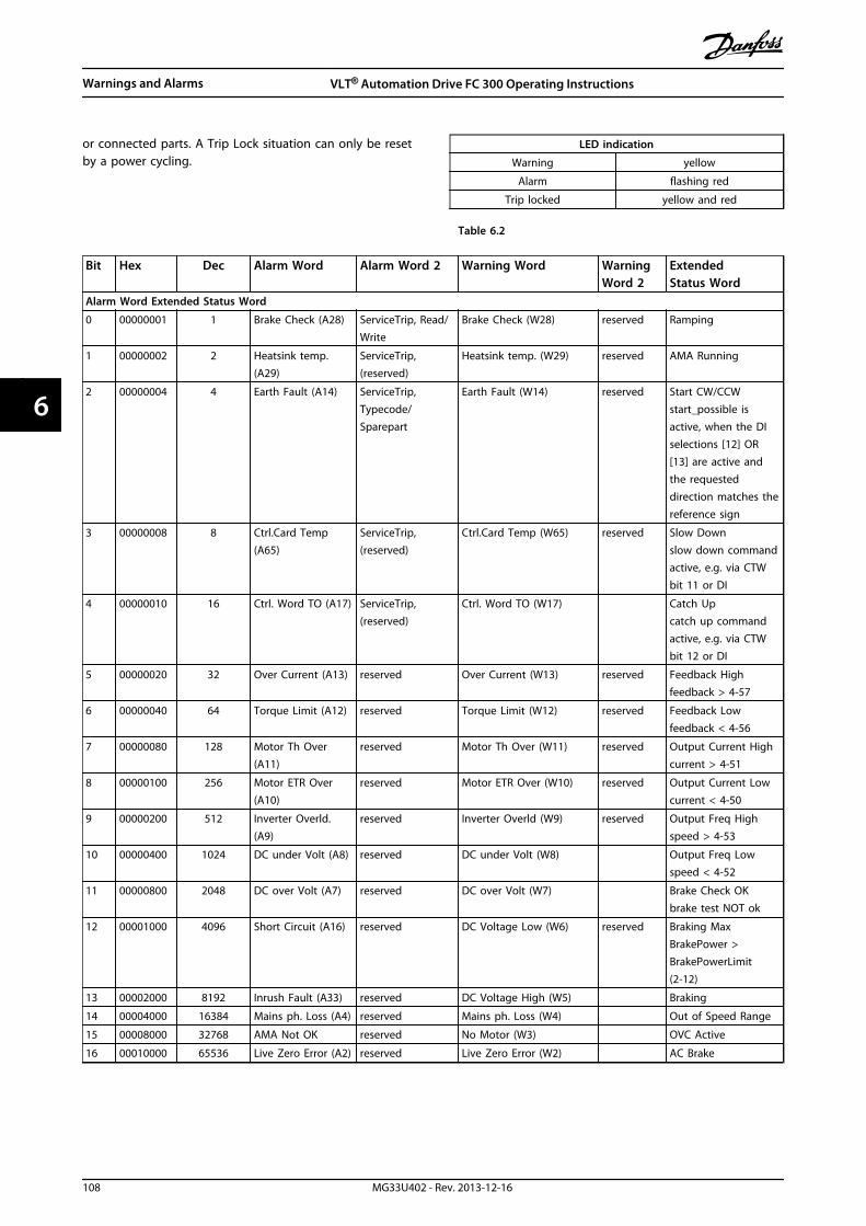
or connected parts. A Trip Lock situation can only be resetby a power cycling.
LED indication
Warning yellow
Alarm flashing red
Trip locked yellow and red
Table 6.2
Bit Hex Dec Alarm Word Alarm Word 2 Warning Word WarningWord 2
ExtendedStatus Word
Alarm Word Extended Status Word
0 00000001 1 Brake Check (A28) ServiceTrip, Read/Write
Brake Check (W28) reserved Ramping
1 00000002 2 Heatsink temp.(A29)
ServiceTrip,(reserved)
Heatsink temp. (W29) reserved AMA Running
2 00000004 4 Earth Fault (A14) ServiceTrip,Typecode/Sparepart
Earth Fault (W14) reserved Start CW/CCWstart_possible isactive, when the DIselections [12] OR[13] are active andthe requesteddirection matches thereference sign
3 00000008 8 Ctrl.Card Temp(A65)
ServiceTrip,(reserved)
Ctrl.Card Temp (W65) reserved Slow Downslow down commandactive, e.g. via CTWbit 11 or DI
4 00000010 16 Ctrl. Word TO (A17) ServiceTrip,(reserved)
Ctrl. Word TO (W17) Catch Upcatch up commandactive, e.g. via CTWbit 12 or DI
5 00000020 32 Over Current (A13) reserved Over Current (W13) reserved Feedback Highfeedback > 4-57
6 00000040 64 Torque Limit (A12) reserved Torque Limit (W12) reserved Feedback Lowfeedback < 4-56
7 00000080 128 Motor Th Over(A11)
reserved Motor Th Over (W11) reserved Output Current Highcurrent > 4-51
8 00000100 256 Motor ETR Over(A10)
reserved Motor ETR Over (W10) reserved Output Current Lowcurrent < 4-50
9 00000200 512 Inverter Overld.(A9)
reserved Inverter Overld (W9) reserved Output Freq Highspeed > 4-53
10 00000400 1024 DC under Volt (A8) reserved DC under Volt (W8) Output Freq Lowspeed < 4-52
11 00000800 2048 DC over Volt (A7) reserved DC over Volt (W7) Brake Check OKbrake test NOT ok
12 00001000 4096 Short Circuit (A16) reserved DC Voltage Low (W6) reserved Braking MaxBrakePower >BrakePowerLimit(2-12)
13 00002000 8192 Inrush Fault (A33) reserved DC Voltage High (W5) Braking
14 00004000 16384 Mains ph. Loss (A4) reserved Mains ph. Loss (W4) Out of Speed Range
15 00008000 32768 AMA Not OK reserved No Motor (W3) OVC Active
16 00010000 65536 Live Zero Error (A2) reserved Live Zero Error (W2) AC Brake
Warnings and Alarms VLT® Automation Drive FC 300 Operating Instructions
108 MG33U402 - Rev. 2013-12-16
66

Bit Hex Dec Alarm Word Alarm Word 2 Warning Word WarningWord 2
ExtendedStatus Word
17 00020000 131072 Internal Fault (A38) KTY error 10V Low (W1) KTY Warn Password Timelocknumber of allowedpassword trialsexceeded - timelockactive
18 00040000 262144 Brake Overload(A26)
Fans error Brake Overload (W26) Fans Warn Password Protection0-61 =ALL_NO_ACCESS ORBUS_NO_ACCESS ORBUS_READONLY
19 00080000 524288 U phase Loss (A30) ECB error Brake Resistor (W25) ECB Warn Reference Highreference > 4-55
20 00100000 1048576 V phase Loss (A31) reserved Brake IGBT (W27) reserved Reference Lowreference < 4-54
21 00200000 2097152 W phase Loss (A32) reserved Speed Limit (W49) reserved Local Referencereference site =REMOTE -> auto onpressed & active
22 00400000 4194304 Fieldbus Fault (A34) reserved Fieldbus Fault (W34) reserved Protection Mode
23 00800000 8388608 24 V Supply Low(A47)
reserved 24V Supply Low (W47) reserved Unused
24 01000000 16777216 Mains Failure (A36) reserved Mains Failure (W36) reserved Unused
25 02000000 33554432 1.8V Supply Low(A48)
reserved Current Limit (W59) reserved Unused
26 04000000 67108864 Brake Resistor (A25) reserved Low Temp (W66) reserved Unused
27 08000000 134217728 Brake IGBT (A27) reserved Voltage Limit (W64) reserved Unused
28 10000000 268435456 Option Change(A67)
reserved Encoder loss (W90) reserved Unused
29 20000000 536870912 DriveInitialized(A80)
Feedback Fault(A61, A90)
Feedback Fault (W61,W90)
Unused
30 40000000 1073741824 Safe Stop (A68) PTC 1 Safe Stop(A71)
Safe Stop (W68) PTC 1 SafeStop (W71)
Unused
31 80000000 2147483648 Mech. brake low(A63)
Dangerous Failure(A72)
Extended Status Word Unused
Table 6.3 Description of Alarm Word, Warning Word and Extended Status Word
The alarm words, warning words and extended statuswords can be read out via serial bus or optional fieldbusfor diagnose. See also 16-94 Ext. Status Word.
Warnings and Alarms VLT® Automation Drive FC 300 Operating Instructions
MG33U402 - Rev. 2013-12-16 109
6 6
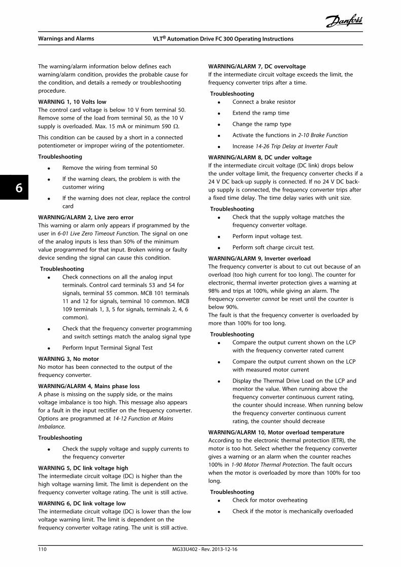
The warning/alarm information below defines eachwarning/alarm condition, provides the probable cause forthe condition, and details a remedy or troubleshootingprocedure.
WARNING 1, 10 Volts lowThe control card voltage is below 10 V from terminal 50.Remove some of the load from terminal 50, as the 10 Vsupply is overloaded. Max. 15 mA or minimum 590 Ω.
This condition can be caused by a short in a connectedpotentiometer or improper wiring of the potentiometer.
Troubleshooting
• Remove the wiring from terminal 50
• If the warning clears, the problem is with thecustomer wiring
• If the warning does not clear, replace the controlcard
WARNING/ALARM 2, Live zero errorThis warning or alarm only appears if programmed by theuser in 6-01 Live Zero Timeout Function. The signal on oneof the analog inputs is less than 50% of the minimumvalue programmed for that input. Broken wiring or faultydevice sending the signal can cause this condition.
Troubleshooting• Check connections on all the analog input
terminals. Control card terminals 53 and 54 forsignals, terminal 55 common. MCB 101 terminals11 and 12 for signals, terminal 10 common. MCB109 terminals 1, 3, 5 for signals, terminals 2, 4, 6common).
• Check that the frequency converter programmingand switch settings match the analog signal type
• Perform Input Terminal Signal Test
WARNING 3, No motorNo motor has been connected to the output of thefrequency converter.
WARNING/ALARM 4, Mains phase lossA phase is missing on the supply side, or the mainsvoltage imbalance is too high. This message also appearsfor a fault in the input rectifier on the frequency converter.Options are programmed at 14-12 Function at MainsImbalance.
Troubleshooting
• Check the supply voltage and supply currents tothe frequency converter
WARNING 5, DC link voltage highThe intermediate circuit voltage (DC) is higher than thehigh voltage warning limit. The limit is dependent on thefrequency converter voltage rating. The unit is still active.
WARNING 6, DC link voltage lowThe intermediate circuit voltage (DC) is lower than the lowvoltage warning limit. The limit is dependent on thefrequency converter voltage rating. The unit is still active.
WARNING/ALARM 7, DC overvoltageIf the intermediate circuit voltage exceeds the limit, thefrequency converter trips after a time.
Troubleshooting• Connect a brake resistor
• Extend the ramp time
• Change the ramp type
• Activate the functions in 2-10 Brake Function
• Increase 14-26 Trip Delay at Inverter Fault
WARNING/ALARM 8, DC under voltageIf the intermediate circuit voltage (DC link) drops belowthe under voltage limit, the frequency converter checks if a24 V DC back-up supply is connected. If no 24 V DC back-up supply is connected, the frequency converter trips aftera fixed time delay. The time delay varies with unit size.
Troubleshooting• Check that the supply voltage matches the
frequency converter voltage.
• Perform input voltage test.
• Perform soft charge circuit test.
WARNING/ALARM 9, Inverter overloadThe frequency converter is about to cut out because of anoverload (too high current for too long). The counter forelectronic, thermal inverter protection gives a warning at98% and trips at 100%, while giving an alarm. Thefrequency converter cannot be reset until the counter isbelow 90%.The fault is that the frequency converter is overloaded bymore than 100% for too long.
Troubleshooting• Compare the output current shown on the LCP
with the frequency converter rated current
• Compare the output current shown on the LCPwith measured motor current
• Display the Thermal Drive Load on the LCP andmonitor the value. When running above thefrequency converter continuous current rating,the counter should increase. When running belowthe frequency converter continuous currentrating, the counter should decrease
WARNING/ALARM 10, Motor overload temperatureAccording to the electronic thermal protection (ETR), themotor is too hot. Select whether the frequency convertergives a warning or an alarm when the counter reaches100% in 1-90 Motor Thermal Protection. The fault occurswhen the motor is overloaded by more than 100% for toolong.
Troubleshooting• Check for motor overheating
• Check if the motor is mechanically overloaded
Warnings and Alarms VLT® Automation Drive FC 300 Operating Instructions
110 MG33U402 - Rev. 2013-12-16
66

• Check that the motor current set in parameter 1-24 Motor Current is correct
• Ensure that Motor data in parameters 1-20through 1-25 are set correctly
• If an external fan is in use, check in 1-91 MotorExternal Fan that it is selected
• Running AMA in 1-29 Automatic Motor Adaptation(AMA) tunes the frequency converter to themotor more accurately and reduces thermalloading
WARNING/ALARM 11, Motor thermistor over tempThe thermistor might be disconnected. Select whether thefrequency converter gives a warning or an alarm in1-90 Motor Thermal Protection.
Troubleshooting• Check for motor overheating
• Check if the motor is mechanically overloaded
• Check that the thermistor is connected correctlybetween either terminal 53 or 54 (analog voltageinput) and terminal 50 (+10 V supply) and thatthe terminal switch for 53 or 54 is set for voltage.Check 1-93 Thermistor Source selects terminal 53or 54
• When using digital inputs 18 or 19, check thatthe thermistor is connected correctly betweeneither terminal 18 or 19 (digital input PNP only)and terminal 50
• If a KTY sensor is used, check for correctconnection between terminals 54 and 55
• If using a thermal switch or thermistor, check thatthe programming if 1-93 Thermistor Resourcematches sensor wiring
• If using a KTY sensor, check the programming of1-95 KTY Sensor Type, 1-96 KTY ThermistorResource, and 1-97 KTY Threshold level matchsensor wiring
WARNING/ALARM 12, Torque limitThe torque has exceeded the value in 4-16 Torque LimitMotor Mode or the value in 4-17 Torque Limit GeneratorMode. 14-25 Trip Delay at Torque Limit can change this froma warning only condition to a warning followed by analarm.
Troubleshooting• If the motor torque limit is exceeded during ramp
up, extend the ramp up time
• If the generator torque limit is exceeded duringramp down, extend the ramp down time
• If torque limit occurs while running, possiblyincrease the torque limit. Be sure the system canoperate safely at a higher torque
• Check the application for excessive current drawon the motor
WARNING/ALARM 13, Over currentThe inverter peak current limit (approximately 200% of therated current) is exceeded. The warning lasts about 1.5 s,then the frequency converter trips and issues an alarm.This fault may be caused by shock loading or fastacceleration with high inertia loads. If extended mechanicalbrake control is selected, trip can be reset externally.
Troubleshooting
• Remove power and check if the motor shaft canbe turned
• Check that the motor size matches the frequencyconverter
• Check parameters 1-20 to 1-25. for correct motordata
ALARM 14, Earth (ground) faultThere is current from the output phases to ground, eitherin the cable between the frequency converter and themotor or in the motor itself.
Troubleshooting:• Remove power to the frequency converter and
repair the earth fault
• Check for earth faults in the motor by measuringthe resistance to ground of the motor leads andthe motor with a megohmmeter
• Perform current sensor test
ALARM 15, Hardware mismatchA fitted option is not operational with the present controlboard hardware or software.
Record the value of the following parameters and contactthe Danfoss supplier:
• 15-40 FC Type
• 15-41 Power Section
• 15-42 Voltage
• 15-43 Software Version
• 15-45 Actual Typecode String
• 15-49 SW ID Control Card
• 15-50 SW ID Power Card
• 15-60 Option Mounted
• 15-61 Option SW Version (for each option slot)
ALARM 16, Short circuitThere is short-circuiting in the motor or motor wiring.
• Remove power to the frequency converter andrepair the short circuit
WARNING/ALARM 17, Control word timeoutThere is no communication to the frequency converter.The warning is only active when 8-04 Control Word TimeoutFunction is NOT set to OFF.
Warnings and Alarms VLT® Automation Drive FC 300 Operating Instructions
MG33U402 - Rev. 2013-12-16 111
6 6

If 8-04 Control Word Timeout Function is set to Stop andTrip, a warning appears and the frequency converter rampsdown until it trips then displays an alarm.
Troubleshooting:• Check connections on the serial communication
cable
• Increase 8-03 Control Word Timeout Time
• Check the operation of the communicationequipment
• Verify a proper installation based on EMCrequirements
WARNING 22, Hoist mechanical brakeThe report value shows what kind it is.0 = The torque reference was not reached before time-out.1 = There was no brake feedback before the time-out.
WARNING 23, Internal fan faultThe fan warning function is an extra protective functionthat checks if the fan is running/mounted. The fan warningcan be disabled in 14-53 Fan Monitor ([0] Disabled).
For D, E and F enclosures, the regulated voltage to the fanis monitored.
Troubleshooting• Check fan resistance
• Check soft charge fuses
WARNING 24, External fan faultThe fan warning function is an extra protective functionthat checks if the fan is running/mounted. The fan warningcan be disabled in 14-53 Fan Monitor ([0] Disabled).
For D, E and F enclosures, the regulated voltage to the fanis monitored.
Troubleshooting• Check fan resistance
• Check soft charge fuses
WARNING 25, Brake resistor short circuitThe brake resistor is monitored during operation. If a shortcircuit occurs, the brake function is disabled and thewarning appears. The frequency converter is stilloperational but without the brake function. Remove powerto the frequency converter and replace the brake resistor(see 2-15 Brake Check).
WARNING/ALARM 26, Brake resistor power limitThe power transmitted to the brake resistor is calculated asa mean value over the last 120 s of run time. Thecalculation is based on the intermediate circuit voltage andthe brake resistance value set in 2-16 AC brake Max.Current. The warning is active when the dissipated brakingis higher than 90% of the brake resistance power. If [2] Tripis selected in 2-13 Brake Power Monitoring, the frequencyconverter trips when the dissipated braking power reaches100%.
WARNINGThere is a risk of substantial power being transmitted tothe brake resistor if the brake transistor is short-circuited.
WARNING/ALARM 27, Brake chopper faultThe brake transistor is monitored during operation and if ashort circuit occurs, the brake function is disabled and awarning is issued. The frequency converter is stilloperational but, since the brake transistor has short-circuited, substantial power is transmitted to the brakeresistor, even if it is inactive.Remove power to the frequency converter and remove thebrake resistor.
This alarm/warning could also occur should the brakeresistor overheat. Terminals 104 and 106 are available asbrake resistors Klixon inuputs, see Brake ResistorTemperature Switch in the Design Guide.
WARNING/ALARM 28, Brake check failedThe brake resistor is not connected or not working.Check 2-15 Brake Check.
ALARM 29, Heat sink tempThe maximum temperature of the heat sink has beenexceeded. The temperature fault does not reset until thetemperature drops below a defined heat sink temperature.The trip and reset points are different based on thefrequency converter power size.
TroubleshootingCheck for the following conditions
• Ambient temperature too high
• Motor cable too long
• Incorrect airflow clearance above and below thefrequency converter
• Blocked airflow around the frequency converter
• Damaged heat sink fan
• Dirty heat sink
For the D, E and F enclosures, this alarm is based on thetemperature measured by the heat sink sensor mountedinside the IGBT modules. For the F enclosures, this alarmcan also be caused by the thermal sensor in the rectifiermodule.
Troubleshooting• Check fan resistance
• Check soft charge fuses
• IGBT thermal sensor
ALARM 30, Motor phase U missingMotor phase U between the frequency converter and themotor is missing.
Troubleshooting• Remove power from the frequency converter and
check motor phase U
Warnings and Alarms VLT® Automation Drive FC 300 Operating Instructions
112 MG33U402 - Rev. 2013-12-16
66

ALARM 31, Motor phase V missingMotor phase V between the frequency converter and themotor is missing.
Remove power from the frequency converter and checkmotor phase V.
ALARM 32, Motor phase W missingMotor phase W between the frequency converter and themotor is missing.
Remove power from the frequency converter and checkmotor phase W.
ALARM 33, Inrush faultToo many power-ups have occurred within a short timeperiod. Let the unit cool to operating temperature.
WARNING/ALARM 34, communication faultThe fieldbus on the communication option card is notworking.
WARNING/ALARM 36, Mains failureThis warning/alarm is only active if the supply voltage tothe frequency converter is lost and 14-10 Mains Failure isNOT set to [0] No Function.
Troubleshooting• Check the fuses to the frequency converter and
mains power supply to the unit
ALARM 38, Internal faultWhen an internal fault occurs, a code number defined inthe Table 6.4 is displayed.
Troubleshooting• Cycle power
• Check that the option is properly installed
• Check for loose or missing wiring
Contact the Danfoss supplier or service department ifrequired. Note the code number for further trouble-shooting directions.
No. Text0 Serial port cannot be initialised. Contact the
Danfoss supplier or Danfoss Service Department.
256-258 Power EEPROM data is defective or too old.
512 Control board EEPROM data is defective or tooold.
513 Communication time out reading EEPROM data.
514 Communication time out reading EEPROM data.
515 Application oriented control cannot recognize theEEPROM data.
516 Cannot write to the EEPROM because a writecommand is on progress.
517 Write command is under time out.
518 Failure in the EEPROM.
519 Missing or invalid barcode data in EEPROM.
783 Parameter value outside of min/max limits.
1024-1279 A centelegram that has to be sent couldn't besent.
No. Text1281 Digital signal processor flash timeout.
1282 Power micro software version mismatch.
1283 Power EEPROM data version mismatch.
1284 Cannot read digital signal processor softwareversion.
1299 Option SW in slot A is too old.
1300 Option SW in slot B is too old.
1301 Option SW in slot C0 is too old.
1302 Option SW in slot C1 is too old.
1315 Option SW in slot A is not supported (notallowed).
1316 Option SW in slot B is not supported (notallowed).
1317 Option SW in slot C0 is not supported (notallowed).
1318 Option SW in slot C1 is not supported (notallowed).
1379 Option A did not respond when calculatingplatform version.
1380 Option B did not respond when calculatingplatform version.
1381 Option C0 did not respond when calculatingplatform version.
1382 Option C1 did not respond when calculatingplatform version.
1536 An exception in the application oriented control isregistered. Debug information written in LCP.
1792 DSP watchdog is active. Debugging of power partdata, motor oriented control data not transferredcorrectly.
2049 Power data restarted.
2064-2072 H081x: option in slot x has restarted.
2080-2088 H082x: option in slot x has issued a powerup-wait.
2096-2104 H983x: option in slot x has issued a legalpowerup-wait.
2304 Could not read any data from power EEPROM.
2305 Missing SW version from power unit.
2314 Missing power unit data from power unit.
2315 Missing SW version from power unit.
2316 Missint lo_statepage from power unit.
2324 Power card configuration is determined to beincorrect at power up.
2325 A power card has stopped communicating whilemain power is applied.
2326 Power card configuration is determined to beincorrect after the delay for power cards toregister.
2327 Too many power card locations have beenregistered as present.
2330 Power size information between the power cardsdoes not match.
2561 No communication from DSP to ATACD.
2562 No communication from ATACD to DSP (staterunning).
Warnings and Alarms VLT® Automation Drive FC 300 Operating Instructions
MG33U402 - Rev. 2013-12-16 113
6 6

No. Text2816 Stack overflow control board module.
2817 Scheduler slow tasks.
2818 Fast tasks.
2819 Parameter thread.
2820 LCP stack overflow.
2821 Serial port overflow.
2822 USB port overflow.
2836 cfListMempool too small.
3072-5122 Parameter value is outside its limits.
5123 Option in slot A: Hardware incompatible withcontrol board hardware.
5124 Option in slot B: Hardware incompatible withControl board hardware.
5125 Option in slot C0: Hardware incompatible withcontrol board hardware.
5126 Option in slot C1: Hardware incompatible withcontrol board hardware.
5376-6231 Out of memory.
Table 6.4 Code Numbers for Internal Faults
ALARM 39, Heat sink sensorNo feedback from the heat sink temperature sensor.
The signal from the IGBT thermal sensor is not available onthe power card. The problem could be on the power card,on the gate drive card, or the ribbon cable between thepower card and gate drive card.
WARNING 40, Overload of digital output terminal 27Check the load connected to terminal 27 or remove short-circuit connection. Check 5-00 Digital I/O Mode and5-01 Terminal 27 Mode.
WARNING 41, Overload of digital output terminal 29Check the load connected to terminal 29 or remove short-circuit connection. Check 5-00 Digital I/O Mode and5-02 Terminal 29 Mode.
WARNING 42, Overload of digital output on X30/6 oroverload of digital output on X30/7For X30/6, check the load connected to X30/6 or removethe short-circuit connection. Check 5-32 Term X30/6 DigiOut (MCB 101).
For X30/7, check the load connected to X30/7 or removethe short-circuit connection. Check 5-33 Term X30/7 DigiOut (MCB 101).
ALARM 46, Power card supplyThe supply on the power card is out of range.
There are 3 power supplies generated by the switch modepower supply (SMPS) on the power card: 24 V, 5 V, ±18 V.When powered with 24 V DC with the MCB 107 option,only the 24 V and 5 V supplies are monitored. Whenpowered with 3 phase mains voltage, all 3 supplies aremonitored.
WARNING 47, 24V supply lowThe 24 V DC is measured on the control card. The external24 V DC back-up power supply may be overloaded,otherwise contact the Danfoss supplier.
WARNING 48, 1.8V supply lowThe 1.8 V DC supply used on the control card is outside ofallowable limits. The power supply is measured on thecontrol card. Check for a defective control card. If anoption card is present, check for an overvoltage condition.
WARNING 49, Speed limitWhen the speed is not within the specified range in4-11 Motor Speed Low Limit [RPM] and 4-13 Motor SpeedHigh Limit [RPM], the frequency converter shows a warning.When the speed is below the specified limit in 1-86 TripSpeed Low [RPM] (except when starting or stopping) thefrequency converter trips.
ALARM 50, AMA calibration failedContact the Danfoss supplier or Danfoss ServiceDepartment.
ALARM 51, AMA check Unom and Inom
The settings for motor voltage, motor current, and motorpower are wrong. Check the settings in parameters 1-20 to1-25.
ALARM 52, AMA low Inom
The motor current is too low. Check the settings.
ALARM 53, AMA motor too bigThe motor is too big for the AMA to operate.
ALARM 54, AMA motor too smallThe motor is too small for the AMA to operate.
ALARM 55, AMA parameter out of rangeThe parameter values of the motor are outside of theacceptable range. AMA does not run.
ALARM 56, AMA interrupted by userThe user has interrupted the AMA.
ALARM 57, AMA internal faultTry to restart AMA again a number of times, until the AMAis carried out. Note that repeated runs may heat the motorto a level where the resistance Rs and Rr are increased. Inmost cases, however, this is not critical.
ALARM 58, AMA Internal faultContact the Danfoss supplier.
WARNING 59, Current limitThe current is higher than the value in 4-18 Current Limit.Ensure that motor data in parameters 1-20 to 1-25 are setcorrectly. Possibly increase the current limit. Be sure thatthe system can operate safely at a higher limit.
WARNING 60, External interlockExternal interlock has been activated. To resume normaloperation, apply 24 V DC to the terminal programmed forexternal interlock and reset the frequency converter (viaserial communication, digital I/O, or by pressing [Reset]).
Warnings and Alarms VLT® Automation Drive FC 300 Operating Instructions
114 MG33U402 - Rev. 2013-12-16
66

WARNING 61, Tracking errorAn error has been detected between the calculated motorspeed and the speed measurement from the feedbackdevice. The function for Warning/Alarm/ Disable is set in4-30 Motor Feedback Loss Function, error setting in 4-31Motor Feedback Speed Error, and the allowed error time in4-32 Motor Feedback Loss Timeout. During a commissioningprocedure the function may be effective.
WARNING 62, Output frequency at maximum limitThe output frequency is higher than the value set in4-19 Max Output Frequency.
ALARM 64, Voltage LimitThe load and speed combination demands a motorvoltage higher than the actual DC-link voltage.
WARNING/ALARM 65, Control card over temperatureThe control card has reached its trip temperature of 80 °C.
WARNING 66, Heat sink temperature lowThe frequency converter is too cold to operate. Thiswarning is based on the temperature sensor in the IGBTmodule.Increase the ambient temperature of the unit. Also, atrickle amount of current can be supplied to the frequencyconverter whenever the motor is stopped by setting2-00 DC Hold/Preheat Current at 5% and 1-80 Function atStop
TroubleshootingThe heatsink temperature measured as 0 °C could indicatethat the temperature sensor is defective, causing the fanspeed to increase to the maximum. If the sensor wirebetween the IGBT and the gate drive card is disconnected,this warning would result. Also, check the IGBT thermalsensor.
ALARM 67, Option module configuration has changedOne or more options have either been added or removedsince the last power-down. Check that the configurationchange is intentional and reset the unit.
ALARM 68, Safe stop activatedSafe stop has been activated. To resume normal operation,apply 24 V DC to terminal 37, then send a reset signal (viaBus, Digital I/O, or by pressing [Reset]).
ALARM 69, Power card temperaturePower cardtemperatureThe temperature sensor on the power card is either toohot or too cold.
Troubleshooting• Check the operation of the door fans
• Check that the filters for the door fans are notblocked
• Check that the gland plate is properly installedon IP21/IP54 (NEMA 1/12) frequency converters
ALARM 70, Illegal FC configurationThe control card and power card are incompatible. Contactthe supplier with the type code of the unit from thenameplate and the part numbers of the cards to checkcompatibility.
WARNING/ALARM 71, PTC 1 safe stopSafe Stop has been activated from the MCB 112 PTCthermistor card (motor too warm). Normal operation canbe resumed when the MCB 112 applies 24 V DC to T-37again (when the motor temperature reaches an acceptablelevel) and when the digital input from the MCB 112 isdeactivated. When this happens, a reset signal is sent (viaserial communication, digital I/O, or by pressing resetbutton on LCP). Note that if automatic restart is enabled,the motor may start when the fault is cleared.
ALARM 72, Dangerous failureSafe Stop with Trip Lock. Unexpected signal levels on safestop and digital input from the PTC thermistor card.
WARNING 73, Safe stop auto restartSafe stopped. With automatic restart enabled, the motormay start when the fault is cleared.
WARNING 76, Power unit setupThe required number of power units does not match thedetected number of active power units. When replacing anF-frame module, this occurs if the power specific data inthe module power card does not match the rest of thefrequency converter.
Troubleshooting• Confirm the spare part and its power card are the
correct part number
WARNING 77, Reduced power modeThis warning indicates that the frequency converter isoperating in reduced power mode (i.e. less than theallowed number of inverter sections). This warning isgenerated on power cycle when the frequency converter isset to run with fewer inverters and remains on.
ALARM 79, Illegal power section configurationThe scaling card is the incorrect part number or notinstalled. Also MK102 connector on the power card couldnot be installed.
ALARM 80, Drive initialised to default valueParameter settings are initialised to default settings after amanual reset. Reset the unit to clear the alarm.
ALARM 81, CSIV corruptCSIV file has syntax errors.
ALARM 82, CSIV parameter errorCSIV failed to initialise a parameter.
ALARM 85, Dang fail PB:Profibus/Profisafe Error.
ALARM 91, Analog input 54 wrong settingsSwitch S202 has to be set in position OFF (voltage input)when a KTY sensor is connected to analog input terminal54.
Warnings and Alarms VLT® Automation Drive FC 300 Operating Instructions
MG33U402 - Rev. 2013-12-16 115
6 6
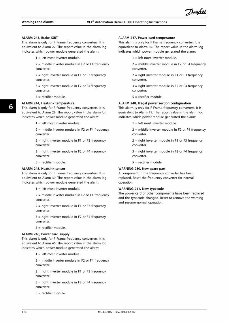
ALARM 243, Brake IGBTThis alarm is only for F Frame frequency converters. It isequivalent to Alarm 27. The report value in the alarm logindicates which power module generated the alarm:
1 = left most inverter module.
2 = middle inverter module in F2 or F4 frequencyconverter.
2 = right inverter module in F1 or F3 frequencyconverter.
3 = right inverter module in F2 or F4 frequencyconverter.
5 = rectifier module.
ALARM 244, Heatsink temperatureThis alarm is only for F Frame frequency converters. It isequivalent to Alarm 29. The report value in the alarm logindicates which power module generated the alarm:
1 = left most inverter module.
2 = middle inverter module in F2 or F4 frequencyconverter.
2 = right inverter module in F1 or F3 frequencyconverter.
3 = right inverter module in F2 or F4 frequencyconverter.
5 = rectifier module.
ALARM 245, Heatsink sensorThis alarm is only for F Frame frequency converters. It isequivalent to Alarm 39. The report value in the alarm logindicates which power module generated the alarm:
1 = left most inverter module.
2 = middle inverter module in F2 or F4 frequencyconverter.
2 = right inverter module in F1 or F3 frequencyconverter.
3 = right inverter module in F2 or F4 frequencyconverter.
5 = rectifier module.
ALARM 246, Power card supplyThis alarm is only for F Frame frequency converters. It isequivalent to Alarm 46. The report value in the alarm logindicates which power module generated the alarm:
1 = left most inverter module.
2 = middle inverter module in F2 or F4 frequencyconverter.
2 = right inverter module in F1 or F3 frequencyconverter.
3 = right inverter module in F2 or F4 frequencyconverter.
5 = rectifier module.
ALARM 247, Power card temperatureThis alarm is only for F Frame frequency converter. It isequivalent to Alarm 69. The report value in the alarm logindicates which power module generated the alarm:
1 = left most inverter module.
2 = middle inverter module in F2 or F4 frequencyconverter.
2 = right inverter module in F1 or F3 frequencyconverter.
3 = right inverter module in F2 or F4 frequencyconverter.
5 = rectifier module.
ALARM 248, Illegal power section configurationThis alarm is only for F Frame frequency converters. It isequivalent to Alarm 79. The report value in the alarm logindicates which power module generated the alarm:
1 = left most inverter module.
2 = middle inverter module in F2 or F4 frequencyconverter.
2 = right inverter module in F1 or F3 frequencyconverter.
3 = right inverter module in F2 or F4 frequencyconverter.
5 = rectifier module.
WARNING 250, New spare partA component in the frequency converter has beenreplaced. Reset the frequency converter for normaloperation.
WARNING 251, New typecodeThe power card or other components have been replacedand the typecode changed. Reset to remove the warningand resume normal operation.
Warnings and Alarms VLT® Automation Drive FC 300 Operating Instructions
116 MG33U402 - Rev. 2013-12-16
66
Index
AAbbreviations.......................................................................................... 5
Access to Control Terminals........................................................... 72
Airflow...................................................................................................... 32
Alarmlog....................................................................................................... 116Messages.......................................................................................... 105
AMA........................................................................................ 77, 111, 114
Analoginputs................................................................................................. 110Inputs................................................................................................... 91Output.................................................................................................. 92signal.................................................................................................. 110
Approvals.................................................................................................. 4
Automatic Motor Adaptation (AMA)................................... 77, 84
BBack cooling.......................................................................................... 32
BrakeCable..................................................................................................... 56Resistor Temperature Switch....................................................... 70
Braking.................................................................................................. 112
Branch circuit protection................................................................. 57
CCable
Lengths and Cross Sections......................................................... 93positions.............................................................................................. 22
Cable-length and cross-section.................................................... 43
Cabling..................................................................................................... 43
Communication option.................................................................. 113
Controlcables................................................................................................... 75Cables................................................................................................... 73card.............................................................................................. 110, 92Card Performance............................................................................ 93card, 24 V DC Output...................................................................... 92card, USB serial communication................................................. 93Characteristics................................................................................... 93Terminals............................................................................................. 72
Conventions............................................................................................. 5
Cooling.................................................................................................... 32
Current rating..................................................................................... 110
DDC link................................................................................................... 110
DeviceNet.................................................................................................. 4
Digitalinput................................................................................................... 111Inputs:.................................................................................................. 90Output.................................................................................................. 92
Disposal..................................................................................................... 6
Drip Shield Installation..................................................................... 36
Ductcooling................................................................................................. 32work cooling kits.............................................................................. 36
EEarth leakage current.......................................................................... 6
ELCB relays............................................................................................. 54
Electrical Installation.................................................................. 72, 73
Enclsoure Type F Options................................................................ 41
ExternalFan Supply.......................................................................................... 57Temperature Monitoring.............................................................. 43
FFeedback.............................................................................................. 114
Fieldbus connection.......................................................................... 70
Floor Mounting.................................................................................... 40
Fuses................................................................................................ 113, 57
Fusing....................................................................................................... 43
GGeneral
Considerations.................................................................................. 19Warning................................................................................................. 7
Gland/Conduit Entry - IP21 (NEMA 1) and IP54 (NEMA12)...... 34
Graphical display................................................................................. 80
Grounding.............................................................................................. 54
IIEC Emergency Stop with Pilz Safety Relay.............................. 42
Inputpolarity of control terminals........................................................ 75terminals........................................................................................... 110
Installationof 24 V external DC Supply........................................................... 72of Duct Cooling Kit in Rittal.......................................................... 36of Input Plate Options.................................................................... 40of Mains Shield for Frequency Converters.............................. 40on Pedestal......................................................................................... 39on the Wall - IP21 (NEMA 1) and IP54 (NEMA 12) Units..... 34
Insulation Resistance Monitor (IRM)........................................... 42
IT mains................................................................................................... 54
LLanguage package............................................................................. 83
Index VLT® Automation Drive FC 300 Operating Instructions
MG33U402 - Rev. 2013-12-16 117
LCP............................................................................................................. 80
LEDs.................................................................................................... 80, 81
Lifting.......................................................................................................... 8
Load Sharing......................................................................................... 56
Local Control Panel............................................................................ 81
MMain reactance..................................................................................... 84
MainsConnection......................................................................................... 56Supply (L1, L2, L3)............................................................................ 90
Manual Motor Starters...................................................................... 42
MechanicalBrake Control..................................................................................... 78dimensions......................................................................................... 17Dimensions........................................................................................ 11Installation.......................................................................................... 19
MotorCable..................................................................................................... 55current............................................................................................... 114data........................................................................................... 111, 114Insulation............................................................................................ 70name plate......................................................................................... 77output.................................................................................................. 90overload protection........................................................................... 6power................................................................................................. 114protection........................................................................................... 94Thermal Protection.......................................................................... 79
NNAMUR.................................................................................................... 42
Non UL compliance............................................................................ 57
Numerical display............................................................................... 81
OOrdering.................................................................................................. 37
Outputcurrent............................................................................................... 110Performance (U, V, W)..................................................................... 90
Outside Installation/NEMA 3R Kit for Rittal............................. 38
PParallel Connection of Motors....................................................... 78
Parameter Menu Structure............................................................. 86
Pedestal Installation.......................................................................... 40
Phase loss............................................................................................. 110
Planning the Installation Site........................................................... 8
Potentiometer Reference................................................................ 77
Power Connections............................................................................ 43
Profibus...................................................................................................... 4
Programming..................................................................................... 110
Protection and Features................................................................... 94
Pulse Start/Stop................................................................................... 76
Pulse/Encoder Inputs........................................................................ 92
RRated Power.......................................................................................... 18
RCD (Residual Current Device)...................................................... 42
Receiving the Frequency Converter.............................................. 8
Relay Outputs....................................................................................... 93
Repair Work.............................................................................................. 7
Reset............................................................................................. 110, 115
Residual Current Device..................................................................... 7
RFI Switch............................................................................................... 54
RS-485 serial communication........................................................ 92
SSafe
Stop + Pilz Relay............................................................................... 42Torque Off............................................................................................. 7
Safety Instructions................................................................................ 6
Screened/armoured........................................................................... 75
Screening of cables............................................................................ 43
Serial Communication....................................................................... 93
Shielded Cables.................................................................................... 55
Short circuit......................................................................................... 111
Sine-wave filter.................................................................................... 44
Smart Application Setup (SAS)...................................................... 83
SpaceSpace.................................................................................................... 19Heaters and Thermostat................................................................ 41
Speed Up/Down................................................................................... 76
Start/Stop............................................................................................... 76
Stator leakage reactance................................................................. 84
Status messages.................................................................................. 80
Supply voltage................................................................................... 113
Surroundings........................................................................................ 94
Switches S201, S202, and S801..................................................... 75
Switching frequency.......................................................................... 43
TTerminal
54......................................................................................................... 115Locations........................................................................................ 1, 23
Thermal Protection............................................................................... 4
Thermistor........................................................................................... 111
TorqueTorque.................................................................................................. 54Characteristics................................................................................... 90for Terminals...................................................................................... 55
Index VLT® Automation Drive FC 300 Operating Instructions
118 MG33U402 - Rev. 2013-12-16
UUnintended Start................................................................................... 7
Unpacking................................................................................................. 8
VVoltage
imbalance......................................................................................... 110level....................................................................................................... 90reference via a potentiometer.................................................... 77
VVCplus...................................................................................................... 5
WWarnings.............................................................................................. 105
Wire access............................................................................................. 19
Index VLT® Automation Drive FC 300 Operating Instructions
MG33U402 - Rev. 2013-12-16 119
www.danfoss.com/drives
Danfoss can accept no responsibility for possible errors in catalogues, brochures and other printed material. Danfoss reserves the right to alter its products without notice. This also applies toproducts already on order provided that such alterations can be made without subsequential changes being necessary in specifications already agreed. All trademarks in this material are propertyof the respective companies. Danfoss and the Danfoss logotype are trademarks of Danfoss A/S. All rights reserved.
*MG33U402*130R0344 MG33U402 Rev. 2013-12-16