VisualMotion 8 (GPP) Multi-Axis Motion Control Rexroth/Control units/Visual Motion... ·...
86
Troubleshooting Guide DOK-VISMOT-VM*-08VRS**-WA01-AE-P VisualMotion 8 (GPP) Multi-Axis Motion Control
Transcript of VisualMotion 8 (GPP) Multi-Axis Motion Control Rexroth/Control units/Visual Motion... ·...

Troubleshooting Guide
DOK-VISMOT-VM*-08VRS**-WA01-AE-P
VisualMotion 8 (GPP)Multi-Axis Motion Control

About this Documentation VisualMotion 8 Troubleshooting Guide
DOK-VISMOT-VM*-08VRS**-WA01-AE-P
VisualMotion 8 (GPP)
Multi-Axis Motion Control
Troubleshooting Guide
DOK-VISMOT-VM*-08VRS**-WA01-AE-P
• Document Number: 120-2300-B310-01/A
This documentation describes …
• the use of VisualMotion Toolkit for assistance in diagnostcis
• the proper steps for identifying diagnostics faults
• and suggested remedies for clearing faults
Description ReleaseDate
Notes
01 03/2001 Initial Release
2001 Rexroth Indramat GmbH
Copying this document, giving it to others and the use or communicationof the contents thereof without express authority, are forbidden. Offendersare liable for the payment of damages. All rights are reserved in the eventof the grant of a patent or the registration of a utility model or design (DIN34-1).
All rights are reserved with respect to the content of this documentationand the availability of the product.
Rexroth Indramat GmbH • Bgm.-Dr.-Nebel-Str. 2 • 97816 Lohr am Main •Germany • Tel.: 09352/40-0 • Telex: 689421 • Fax: 09352/40-4885
Rexroth Indramat Division • 5150 Prairie Stone Parkway • HoffmanEstates, IL 60192 • USA • Tel.: 847-645-3600 • Fax: 847-645-6201
http://www.rexroth.com/indramat
Dept. ESV3 (DPJ).
Title
Type of Documentation
Document Typecode
Internal File Reference
Purpose of Documentation
Record of Revisions
Copyright
Validity
Published by

VisualMotion 8 Troubleshooting Guide Table of Contents I
DOK-VISMOT-VM*-08VRS**-WA01-AE-P
Table of Contents
1 VisualMotion 8.0 Overview 1-1
System Overview..................................................................................................................................... 1-1
GPP 8.0 System Overview ...................................................................................................... 1-1
System Components................................................................................................................ 1-2
PLC Support............................................................................................................................. 1-2
Interface Support ..................................................................................................................... 1-2
2 VisualMotion Tools for Diagnosing 2-1
2.1 Using VisualMotion Toolkit for Diagnosing .................................................................................... 2-1
VisualMotion to PC Connection ............................................................................................... 2-1
The Diagnostics Menu ............................................................................................................. 2-3
2.2 Using VisualMotion's End User Tool for Diagnosing ..................................................................... 2-7
3 Monitoring and Diagnostics 3-1
3.1 System Diagnostics - Codes and Message ................................................................................... 3-1
Parameters .............................................................................................................................. 3-2
Drive Parameter Editor ............................................................................................................ 3-3
3.2 Status Messages (001-199) ........................................................................................................... 3-4
001 Initializing System ............................................................................................................. 3-4
002 Parameter Mode ............................................................................................................... 3-4
003 Initializing Drives ............................................................................................................... 3-4
004 System is Ready ............................................................................................................... 3-4
005 Manual Mode .................................................................................................................... 3-4
006 Automatic Mode: ABCD.................................................................................................... 3-4
007 Program Running: ABCD.................................................................................................. 3-5
008 Single-Stepping: ABCD..................................................................................................... 3-5
009 Select Parameter Mode to Continue................................................................................. 3-5
010 Breakpoint Reached: ABCD ............................................................................................. 3-5
011 Waiting for PLC................................................................................................................. 3-5
018 Please cycle power to continue ........................................................................................ 3-5
3.3 Warning Messages (201-399)........................................................................................................ 3-6
201 Invalid jog type or axis selected........................................................................................ 3-7
202 Drive D is not ready .......................................................................................................... 3-7
203 Power lost during program................................................................................................ 3-7
204 SERCOS Ring was disconnected..................................................................................... 3-7
205 Parameter transfer warning in Task A .............................................................................. 3-8
206 Battery is low: replace it soon ........................................................................................... 3-8
207 Axis D position limit reached............................................................................................. 3-8

II Table of Contents VisualMotion 8 Troubleshooting Guide
DOK-VISMOT-VM*-08VRS**-WA01-AE-P
208 Lost Fieldbus connection .................................................................................................. 3-9
209 Fieldbus Mapping Timeout ............................................................................................... 3-9
210 File System Defrag: #% completed ................................................................................ 3-10
211 Program & Data memory cleared ................................................................................... 3-10
212 External PLS Warning..................................................................................................... 3-10
213 SERCOS Cycle Time Changed ...................................................................................... 3-10
214 PLC Cyclic Mapping Timeout ......................................................................................... 3-10
3.4 Shutdown Messages (400 - 599) ................................................................................................. 3-11
400 EMERGENCY STOP...................................................................................................... 3-11
401 SERCOS Controller Error: DD........................................................................................ 3-11
402 SERCOS Config. Error: see ext. diag............................................................................ 3-12
405 Phase D: Drive did not respond...................................................................................... 3-12
407 Drive D Phase 3 Switch Error ......................................................................................... 3-12
409 SERCOS Disconnect Error ............................................................................................. 3-13
411 Drive D Phase 4 Switch Error ......................................................................................... 3-14
412 No drives were found on ring.......................................................................................... 3-15
414 Parameters were lost ...................................................................................................... 3-15
415 Drive D was not found..................................................................................................... 3-15
416 Invalid Instruction at XXXX ............................................................................................. 3-16
417 SYSTEM ERROR: pSOS #XXXX................................................................................... 3-16
418 No program is active ....................................................................................................... 3-16
419 Invalid Program File: Code =x ........................................................................................ 3-16
420 Drive D Shutdown Error .................................................................................................. 3-17
421 User Program Stack Overflow ........................................................................................ 3-17
422 Parameter transfer error in Task #.................................................................................. 3-17
423 Unimplemented Instruction ............................................................................................. 3-18
425 Instruction Error: see Task # diag................................................................................... 3-18
426 Drive D is not ready ........................................................................................................ 3-18
427 Calc: invalid table index D............................................................................................... 3-19
428 Calc: division by zero ...................................................................................................... 3-19
429 Calc: too many operands................................................................................................ 3-20
430 Calc instruction: invalid operator..................................................................................... 3-20
431 Calc error: see Task A diag. ........................................................................................... 3-20
432 Calc: too many nested expressions................................................................................ 3-20
433 Setup instruction outside of a task.................................................................................. 3-20
434 Axis D configured more than once.................................................................................. 3-21
435 Axis D not assigned to a task ......................................................................................... 3-21
436 General Compiler Error: XXXX ....................................................................................... 3-21
438 Invalid Axis Selected: D .................................................................................................. 3-21
439 Axis #: Invalid Motion Type............................................................................................. 3-22
440 I-O Transfer Error: see task diag. ................................................................................... 3-22
450 Event D: invalid event type ............................................................................................. 3-22
451 Invalid event number D................................................................................................... 3-23
452 More than D event timers armed .................................................................................... 3-23
453 Homing param. transfer error: D.................................................................................... 3-23
454 Axis D homing not complete ........................................................................................... 3-23

VisualMotion 8 Troubleshooting Guide Table of Contents III
DOK-VISMOT-VM*-08VRS**-WA01-AE-P
459 Axis D target position out of bounds ............................................................................... 3-24
460 Invalid program D from binary inputs.............................................................................. 3-24
463 Ratio command: invalid ratio .......................................................................................... 3-24
464 Can't activate while program running.............................................................................. 3-25
465 Drive D config. error, see ext. diag, or ........................................................................... 3-25
467 Invalid ELS Master Option .............................................................................................. 3-26
468 ELS adjustment out of bounds........................................................................................ 3-26
470 Axis D velocity > maximum............................................................................................. 3-26
474 Drive D cyclic data size too large.................................................................................... 3-26
475 Axis D capture already configured.................................................................................. 3-27
477 Axis D: probe edge not configured ................................................................................. 3-27
478 Calc: operand out of range ............................................................................................. 3-27
481 Event D is already armed ............................................................................................... 3-28
482 Checksum Error in Program ........................................................................................... 3-28
483 Parameter Init. Error: see Task A diag ........................................................................... 3-28
484 Control SYSTEM ERROR............................................................................................... 3-28
486 SERCOS Device D is not a drive.................................................................................... 3-29
487 Cam D is invalid or not stored......................................................................................... 3-29
488 Cam Error: See Task # diag. .......................................................................................... 3-29
489 More than D CAM axes selected .................................................................................... 3-29
490 System Memory Allocation Error .................................................................................... 3-30
492 Programs were lost ......................................................................................................... 3-30
493 Data was restored from Flash......................................................................................... 3-30
494 Sequencer init. error: see task T diag............................................................................ 3-30
495 Sequencer error: see task T diag. .................................................................................. 3-31
496 Can't Execute this Instruction from an Event.................................................................. 3-31
497 Limit switch config. error, see ext. diag.......................................................................... 3-32
498 Drive D Shutdown Warning ............................................................................................ 3-32
499 Axis number D not supported in this version .................................................................. 3-32
500 Axis D is not referenced.................................................................................................. 3-32
501 Drive D comm. error, see ext. diag. ................................................................................ 3-33
502 ELS and CAMs not supported in this version ................................................................. 3-33
504 Communication Timeout ................................................................................................. 3-33
505 Axis D is not configured .................................................................................................. 3-34
506 I-O Mapper initialization error ......................................................................................... 3-34
508 User Watchdog Timeout ................................................................................................. 3-34
509 Control System Timing Error D....................................................................................... 3-35
514 Control SYSTEM ERROR D........................................................................................... 3-35
515 PLC Communications Error ............................................................................................ 3-35
516 More than D registration mark limit exceeded ................................................................ 3-36
519 Lost Fieldbus Connection ............................................................................................... 3-36
520 Fieldbus mapping timeout............................................................................................... 3-36
521 Invalid Virtual Master ID: %d........................................................................................... 3-37
522 Invalid ELS Master ID: %d.............................................................................................. 3-38
524 Hardware Watchdog timeout .......................................................................................... 3-38
525 I/O Configuration error, see extended diagnosis ............................................................ 3-39

IV Table of Contents VisualMotion 8 Troubleshooting Guide
DOK-VISMOT-VM*-08VRS**-WA01-AE-P
526 SERCOS Multiplex Channel Configuration, see ext. diag .............................................. 3-39
527 Control Initialization Error, see ext. diag ......................................................................... 3-40
528 System Event %d Occurred............................................................................................ 3-40
529 Invalid ELS Group ID: %d............................................................................................... 3-40
530 Cam # is active, can't overwrite ...................................................................................... 3-41
531 Invalid variable for Fieldbus Mapping ............................................................................. 3-41
532 Power fail brown out condition detected ......................................................................... 3-41
533 Multiple instances of index CAM: #................................................................................. 3-41
534 Hardware version not supported..................................................................................... 3-42
535 Invalid Conveyor ID: %d ................................................................................................. 3-42
536 Multiple Instance of Conveyor with ID: %d ..................................................................... 3-42
537 Conveyor Assigned to an Invalid Axis Number: %d ....................................................... 3-42
538 Conveyor Secondary Feedback Invalid for Axis: %d...................................................... 3-42
539 Invalid Parameter Number.............................................................................................. 3-42
540 External PLS Card error.................................................................................................. 3-43
541 Link Ring Error, see ext. diag. ........................................................................................ 3-44
542 PLC Cyclic Mapping Timeout ......................................................................................... 3-44
543 PLC Runtime Error.......................................................................................................... 3-45
3.5 Communication Error Codes and Messages ............................................................................... 3-45
!01 SERCOS Error Code # xxxx (xxxx = Error code) ........................................................... 3-45
!02 Invalid Parameter Number.............................................................................................. 3-45
!03 Data is Read Only........................................................................................................... 3-45
!04 Write Protected in this mode/phase................................................................................ 3-45
!05 Greater than maximum value ......................................................................................... 3-45
!06 Less than minimum value ............................................................................................... 3-46
!07 Data is Invalid ................................................................................................................. 3-46
!08 Drive was not found ........................................................................................................ 3-46
!09 Drive not ready for communication ................................................................................. 3-46
!10 Drive is not responding ................................................................................................... 3-46
!11 Service channel is not open............................................................................................ 3-46
!12 Invalid Command Class.................................................................................................. 3-46
!13 Checksum Error: xx (xx= checksum that control calculated).......................................... 3-46
!14 Invalid Command Subclass ............................................................................................ 3-46
!15 Invalid Parameter Set ..................................................................................................... 3-46
!16 List already in progress................................................................................................... 3-46
!17 Invalid Sequence Number .............................................................................................. 3-47
!18 List has not started.......................................................................................................... 3-47
!19 List is finished ................................................................................................................. 3-47
!20 Parameter is a List .......................................................................................................... 3-47
!21 Parameter is not a List .................................................................................................... 3-47
!22 Invalid Variable Number ................................................................................................. 3-47
!23 Insufficient Program Space............................................................................................. 3-47
!24 Maximum number of files exceeded ............................................................................... 3-47
!25 Invalid Program Header .................................................................................................. 3-47
!26 Checksum Error in Program ........................................................................................... 3-48
!27 Invalid Program Handle .................................................................................................. 3-48

VisualMotion 8 Troubleshooting Guide Table of Contents V
DOK-VISMOT-VM*-08VRS**-WA01-AE-P
!28 Function not Implemented .............................................................................................. 3-48
!29 Program not found on Control ........................................................................................ 3-48
!30 Invalid I/O Register or Bit Number .................................................................................. 3-48
!31 Invalid Table Index.......................................................................................................... 3-48
!32 Communication Port Error .............................................................................................. 3-48
!33 Invalid Data Format......................................................................................................... 3-48
!34 Active program can't be deleted ..................................................................................... 3-48
!35 Parameter mode is required ........................................................................................... 3-48
!36 Invalid Event Number...................................................................................................... 3-49
!37 Invalid Event Function..................................................................................................... 3-49
!38 Program file version mismatch ....................................................................................... 3-49
!39 Can't activate while program running.............................................................................. 3-49
!40 No programs are active................................................................................................... 3-49
!41 System Error: pSOS #XXXX........................................................................................... 3-49
!42 Mapper: invalid operator ................................................................................................. 3-49
!43 Mapper: too many operations ......................................................................................... 3-49
!44 Mapper: invalid register................................................................................................... 3-49
!45 Mapper: invalid bit or mask............................................................................................. 3-49
!46 Mapper: register is read-only .......................................................................................... 3-49
!47 Invalid Unit Number ........................................................................................................ 3-50
!50 Invalid Download Block................................................................................................... 3-50
!52 Invalid Axis...................................................................................................................... 3-50
!53 Waiting for service channel............................................................................................. 3-50
!54 List or String is too short ................................................................................................. 3-50
!55 List or String is too long .................................................................................................. 3-50
!56 PC Communication Handshake Error............................................................................. 3-50
!57 I/O Mapper: Max file size on Control Exceeded ............................................................. 3-50
!58 Cannot store CAM: already active for axis D.................................................................. 3-50
!59 SERCOS handshake/busy timeout................................................................................. 3-51
!60 Executable program is too large (ddK) ........................................................................... 3-51
!61 System Memory Allocation Error .................................................................................... 3-51
!62 Cam X data is < 0 or greater than 360 ........................................................................... 3-51
!63 X-Column does not start at 0 or end at 360.................................................................... 3-51
!64 Not supported in user prog file version 1.1 ..................................................................... 3-51
!65 Sequencer: invalid sequence (D).................................................................................... 3-51
!66 Sequencer: invalid step (D) ............................................................................................ 3-51
!67 Invalid function number (D)............................................................................................. 3-51
!68 Function D not accessible in a step ................................................................................ 3-52
!69 Too many functions are used (D) ................................................................................... 3-52
!70 Maximum steps per sequence exceeded (D) ................................................................. 3-52
!71 Maximum functions per step exceeded (D) .................................................................... 3-52
!72 Program does not include a PLS .................................................................................... 3-52
!73 Invalid ABS or REL point index (D)................................................................................. 3-52
!74 Error in command execution........................................................................................... 3-52
!75 Comm. port buffer overflow............................................................................................. 3-52
!77 Can't save sequencer while it is running ........................................................................ 3-52

VI Table of Contents VisualMotion 8 Troubleshooting Guide
DOK-VISMOT-VM*-08VRS**-WA01-AE-P
!78 Service channel in use.................................................................................................... 3-53
!79 PID block number does not exist .................................................................................... 3-53
!80 IBS: Invalid Object Number ............................................................................................ 3-53
!81 IBS: Invalid Mapping(s)................................................................................................... 3-53
!82 Write protected by password .......................................................................................... 3-53
!83 Valid ELS Group numbers are 1 through 8..................................................................... 3-53
!84 ELS Group is not currently active ................................................................................... 3-53
!85 Data not limited to a specific ELS Master ....................................................................... 3-53
!86 No ELS Masters are currently active .............................................................................. 3-54
!87 Valid Virtual Master numbers are 1 and 2 ...................................................................... 3-54
!88 No Virtual Master are currently active............................................................................. 3-54
!89 Unsupported Parameter for mapping ............................................................................. 3-54
!90 Invalid variable for mapping............................................................................................ 3-54
!91 CAM build: float table start index # ................................................................................. 3-54
!92 CAM build: float table end index # .................................................................................. 3-54
!93 CAM build: float table size # ........................................................................................... 3-54
!94 Valid Conveyor numbers are 1 through 4........................................................................ 3-54
!95 Conveyor number is not currently active ......................................................................... 3-55
!96 Duplicate Message Sequence Number (MSN)................................................................ 3-55
!97 Requested operation prohibited from network................................................................. 3-55
!98 Conveyor is not available in this version.......................................................................... 3-55
4 Index 4-1
5 Service & Support 5-1

VisualMotion 8 Troubleshooting Guide VisualMotion 8.0 Overview 1-1
DOK-VISMOT-VM*-08VRS**-WA01-AE-P 03/2001
1 VisualMotion 8.0 Overview
System Overview
VisualMotion is a programmable multi-axis motion control system capableof controlling up to 32 digital intelligent drives from Rexroth Indramat. ThePC software used for motion control management is named VisualMotionToolkit. The hardware used with VisualMotion 8 GPP firmware is thePPC-R control.
PPC-R02.2PPC-R01.2
RECO RECO
PPC-R01.2
H1
PR
OG
U2X10X1
I1
I3I2
Q1Q2
24Ve0VeBbBb24V0V
S1
RX
TX
U1RESETS2
H2DIST
PPC-R02.2
H1
PR
OG
U2
X10X1
Q1Q2
24Ve0VeBbBb24V0V
S1
RX
TX
U1RESETS2
H2DIST
CO
M
X16
U3 U4
I1
I3I2
Fig. 1-1: PPC-R Motion Control
GPP 8.0 System OverviewThe PPC-R is a stand-alone multi-axis motion control. It has theRECO02 form factor, a form factor used by Rexroth Indramat for motioncontrols, PLCs and I/O modules. These devices share the RECO02back-plane bus for data exchange.
It is recommended to use the VisualMotion motion control with RexrothIndramat's DIAX04 and/or ECODRIVE03 digital servo drives. Thecommunication between control and digital servo drives is performedusing the SERCOS fiber optic interface, the international standard forreal-time communication.
VisualMotion can provide multi-axis coordinated or non-coordinatedmotion control with tightly integrated RECO02 I/O logic control functions.The flexibility of GPP firmware supports a variety of applications, fromgeneral motion control to sophisticated multiple master electronic lineshafting (ELS) and robotics.
1-2 VisualMotion 8.0 Overview VisualMotion 8 Troubleshooting Guide
03/2001 DOK-VISMOT-VM*-08VRS**-WA01-AE-P
System ComponentsThe VisualMotion 8 system is composed of the following components:
• PPC-R control using GPP 8 firmware.
• RECO02 I/O modules.
• VisualMotion Toolkit (VMT) Windows program for motion controlprogramming, parametrization, system diagnostics and motion controlmanagement. VMT also includes a DDE Server (communicationprotocol between Windows programs and the control).
• DIAX04 (with SSE03 or ELS05 firmware) or ECODRIVE03 (SMT01,SMT02, SGP01 or SGP03 firmware) drives and motors. Up to 32intelligent digital drives can be connected to one control over theSERCOS fiber optic ring.
• HMI interfaces (BTC06, BTV04, BTV05, BTV06).
PLC SupportThe Rexroth Indramat MTS-R is a PLC that interfaces with theVisualMotion system and is available preconfigured in two sizes.
• MTS-R01.1 with one expansion slot.
• MTS-R02.1 with three expansion slot.
The expansions slot(s) can be configured with, e.g., fieldbus or serialinterface cards.
Interface SupportVisualMotion GPP 8 supports the following interfaces:
• Fieldbus Interfaces:
• Profibus-DP slave interface(32 words).
• DeviceNet slave interface (32 words).
• Interbus slave interface (14 words).
• ControlNet slave interface.
• Additional Interfaces:
• Ethernet Interface.
• Optional Card Programmable Limit Switch (16 or 32 outputs).
• Link Ring for Master/Slave interfacing of PPC-R controls.

VisualMotion 8 Troubleshooting Guide VisualMotion Tools for Diagnosing 2-1
DOK-VISMOT-VM*-08VRS**-WA01-AE-P 03/2001
2 VisualMotion Tools for Diagnosing
2.1 Using VisualMotion Toolkit for Diagnosing
VisualMotion Toolkit 8 (VMT) is Indramat's Windows baseddevelopment environment for programming VisualMotion Controls. Alongwith VMT's programming capabilities, it can also be used to help diagnoseVisualMotion programs, control and drive diagnostics.
Note: The information provided in this section is intended to illustrateonly those screens in VisualMotion Toolkit that can assist indetermining a diagnostic fault. For a complete description ofVisualMotion Toolkit's menu selections, refer to theVisualMotion 8 Functional Description.
VisualMotion to PC ConnectionTo establish communications between VisualMotion (PC) and the PPC-Rcontrol, use an IKB0005 standard RS-232 serial communication cable.
RECO
PPC-R02.2
H1
PR
OG
U2
X10X1
Q1Q2
24Ve0VeBbBb24V0V
S1
RX
TX
U1RESETS2
H2DIST
CO
M
X16
U3 U4
8888
I1
I3I2
IKB0005PPC-R_Serial.FH7
Fig. 2-1: VisualMotion (PC) to PPC-R Serial Connection
Use the following procedure to confirm hardware connections.
1. Connect communication cable IKB0005 between PPC-R X10 and thePC's Com port.
2. Power-up VisualMotion System (drives, control, motors, etc.).
3. Start VisualMotion 8 Toolkit.
4. From the VisualMotion Toolkit main menu, select Diagnostics ⇒
System . If the System Parameters screen loads with information,communications have been established. The user is now ready touse VisualMotion Toolkit.
Note: If a connection can not be established, the DDE server willissue an error and the following Diagnostic dialog box willopen. This indicates that either there is a problem in thephysical connection or that the communication settings of thecontrol do not match the settings of the DDE sever.

2-2 VisualMotion Tools for Diagnosing VisualMotion 8 Troubleshooting Guide
03/2001 DOK-VISMOT-VM*-08VRS**-WA01-AE-P
Fig. 2-2: VisualMotion DDE Server Error
5. Verify that power has been applied to the control and the proper cableis being used (IKB0005) and the connections on both ends are made.If this does not resolve the problem, then the serial parametersshould be verified.
6. To view the current serial port settings on the PPC-R control, pushthe S1 button and read the H1 display as follows.
Press S1 #of Times
Description
0 System Diagnostic Message
1 Firmware version
2 X10 communications type (RS-232, RS-422, RS-485)
3 X10 baud rate (300, 1200, 2400, 4800, 9600, 19.2K, 38.4K,57.6K, 115.2K)
4 X16 communications type (RS-232, RS-422, RS-485)
5 X16 baud rate (300, 1200, 2400, 4800, 9600, 19.2K, 38.4K,57.6K, 115.2K)
6 Unit number (0 to 31, used for RS-485 mode)
Table 2-1: PPC-R S1 Button Display
7. Selecting Settings for the screen in Fig. 2-2 will open the dialog box inFig. 2-3. Make sure that the baud rate setting in the SerialCommunication window matches the PPC-R's setting. Also, verifythat the Serial Port number matches that of the port used by serialcable. Checking Use Serial Event improves the communicationthroughput of the PC hardware.

VisualMotion 8 Troubleshooting Guide VisualMotion Tools for Diagnosing 2-3
DOK-VISMOT-VM*-08VRS**-WA01-AE-P 03/2001
Fig. 2-3: Serial Communications
After you have established a connection to the control, the hardware baudrate can be modified. From VisualMotion Toolkit's main menu, selectSettings ⇒ Control Serial Ports.
Port 1 = X10
Port 2 = X16
Note: The new baud rate does not take effect until the system isplaced in and out of parameter mode. Afterwards, you willneed to adjust the DDE server baud rate after the newhardware rate takes effect.
The Diagnostics MenuThe diagnostics menu provides status information for logging andmonitoring system errors and diagnostics.
Fig. 2-4: Diagnostics Menu
Diagnostic Log…The diagnostic log screen displays the last 100 errors that the control hasencountered. Along with the error messages, the date, time andextended error codes are displayed.

2-4 VisualMotion Tools for Diagnosing VisualMotion 8 Troubleshooting Guide
03/2001 DOK-VISMOT-VM*-08VRS**-WA01-AE-P
Diagnostic Help
Error codes displayed in the Diagnostic log contain context sensitive help.Double clicking on an error code will open the help for the selected error.
Fig. 2-5: Diagnostic log
Date and Time
Date and time are relative to the power on of the control; they have nobattery-backup clock unless the PPC-R is order with a battery backup.Refer to chapter 11 of the VisualMotion 8 Project Planning Manual foravailable hardware configuration. After power up, select the Set Timebutton to retrieve the date and time from the PC. The date and time arestored in parameter C-0-0126.
Log Options
This button opens an options window. The user can select what optionsare best suited for their application. Selecting the Log to file button willsave the diagnostic log as a text file. Once the options are set, thesettings can be saved. Also, see card parameter C-0-2020.
Fig. 2-6: Diagnostic Log Options
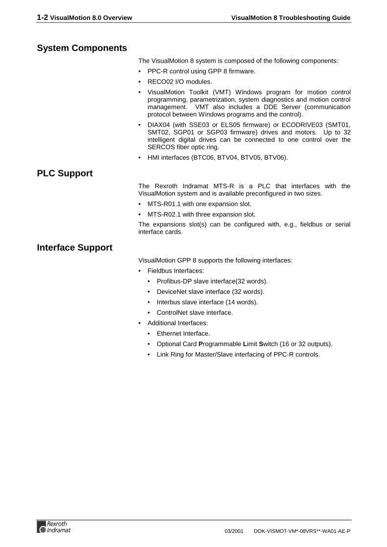
Drives…When opened, the Drive Parameter Editor uploads the current statusinformation for drive #1 (the default). The current drive status is alsodisplayed. The Position, Velocity and Acceleration values from the controlare displayed along with the feedback status from the selected drive. Adifferent drive can be selected by using the pull-down drive selector.
Since the drive internally generates rate profiles for single axis motion, theprogrammed acceleration is also displayed. Acceleration is not shown forcoordinated motion since the Control's path planner managesacceleration for coordinated motion.
VisualMotion 8 Troubleshooting Guide VisualMotion Tools for Diagnosing 2-5
DOK-VISMOT-VM*-08VRS**-WA01-AE-P 03/2001
Drive Selector
Drive Status Message
Fig. 2-7: Drive Parameter Editor
Note : More than one session of VisualMotion's Drive ParameterEditor can be ran by selecting Drives once again from theDiagnostics menu. This can be useful if you want to viewmore than one axis. However, opening additional sessions ofParameter Editor will slow the update time to all sessionsopened.
Note : If the drive controller connected to the VisualMotion systemexperiences an error, the user can obtain drive statusinformation from the Status message displayed withinVisualMotion's Drive Parameter Editor.
System…Choosing System from the Diagnostics menu opens the SystemParameters window. System Parameters displays information about thecurrent control hardware and firmware for the indicated unit number; andthe total memory and free memory on the PPC-R.
In addition, the user can use this screen for retrieving DiagnosticMessage and Extended Diagnostic Message information that can assist indetermining the cause of an error.

2-6 VisualMotion Tools for Diagnosing VisualMotion 8 Troubleshooting Guide
03/2001 DOK-VISMOT-VM*-08VRS**-WA01-AE-P
ControlParameters
C-0-0100C-0-0101C-0-0102C-0-0002
C-0-0091C-0-0092
C-0-0001C-0-0120C-0-0121C-0-0122C-0-0124
Fig. 2-8: System Parameters
TasksSelecting Task from the Diagnostics menu opens the Task_A Parameterswindow and uploads data regarding the active control task. The othertasks may be viewed by clicking on the Previous or Next buttons.
TaskParameters
T-0-0001
T-0-0120
T-0-0130
T-0-0131
T-0-0132
T-0-0123
T-0-0122
T-0-0111T-0-0112T-0-0113
Coordinated Axes datais only available forcoordinated motionprograms.
Fig. 2-9: Task Parameters
Status
Status indicates the type of motion programmed in the selected task forthe active program and the current mode of the control (Parameter,Initialization, Manual or Automatic).
Current Instruction
Current Instruction displays the instruction executing and its pointer, and apointer to a run-time error if one has occurred. This display is usefulwhen debugging in single-step mode. If a program is running inautomatic mode, the displayed instruction is the instruction that was

VisualMotion 8 Troubleshooting Guide VisualMotion Tools for Diagnosing 2-7
DOK-VISMOT-VM*-08VRS**-WA01-AE-P 03/2001
executing at the time that the SERCOS cycle sampled instructionexecution, which may appear to be random.
Current Messages
Current Messages displays the last messages encountered in theprogram.
Coordinated Axes
Coordinated Axes displays the axes in the active task that are assigned tocoordinated motion and their current position.
2.2 Using VisualMotion's End User Tool for Diagnosing
VisualMotion's End User Tool is currently under development. Whenavailable, the tool will provide the user with diagnostic information andparameter accessibility in the following areas:
• Archive and Restore parameters
• Diagnostics for control and drives
• Parameter editing for control, task and axis
• Parameter editing for additional SERCOS devices, such as I/O
• Ability to create and edit Custom parameter list
• Password Security
Fig. 2-10: End User Tool Currently Under Development

2-8 VisualMotion Tools for Diagnosing VisualMotion 8 Troubleshooting Guide
03/2001 DOK-VISMOT-VM*-08VRS**-WA01-AE-P

VisualMotion 8 Troubleshooting Guide Monitoring and Diagnostics 3-1
DOK-VISMOT-VM*-08VRS**-WA01-AE-P 03/2001
3 Monitoring and Diagnostics
3.1 System Diagnostics - Codes and Message
VisualMotion provides three types of diagnostic messages:
• Status messages
• Warning messages
• Shutdown messages
An identifying 3-digit code number precedes diagnostic messages.
Example: 400 Emergency Stop
These identifying code numbers are assigned by Indramat and are brokenup into the following groups:
• (001-199) Status messages
• (201-399) Warning messages
• (400-599) Shutdown messages
Each group above does not contain the range of code numbers indicatedas diagnostic messages. The range of numbers was designed to allowfor future development.
The Host can request the currently active VisualMotion diagnosticmessage for the control and for each user task from the followingparameters.
Control parameters
• Parameter C-0-0122: Displays current diagnostic message
• Parameter C-0-0123: Displays current diagnostic 3-digit code
• Parameter C-0-0124: Displays extended diagnostic message
VisualMotion Task parameters
• Parameter "0x T-0-0122": Displays Task (A-D) diagnostic message
• Parameter "0x T-0-0123": Displays Task (A-D) status message
(Where 0x = 1-4 for Task A-D)
Drive Parameter
• Parameter "xx S-0-0095": Displays Drive diagnostic message
(Where xx = 1-32 for Drive 1-32)
The above diagnostic message parameters can be view by usingVisualMotion Toolkit and selecting On-Line Data ⇒ Parameters from themain menu.

3-2 Monitoring and Diagnostics VisualMotion 8 Troubleshooting Guide
03/2001 DOK-VISMOT-VM*-08VRS**-WA01-AE-P
ParametersSelecting On-Line Data ⇒ Parameters opens the Parameter Overviewwindow shown below. This window is used to view and modify existingControl, Drive, Task and Axis parameters.
Fig. 3-1: Parameter Overview Window
Access to ParametersAccess to parameters is controlled by the Parameter Overview toolwhether in Phase 2 or Phase 4. Parameters are displayed in differentcolors to provide a visual representation of their access level. Thefollowing table explains the color code / access combination.
Color code Access Level
grayed out text read only
black text read/write
blue text parameter list read/write
grayed out parameter list read only
Fig. 3-2: Access to Parameters
Editing a ParameterA parameter can be edited by double clicking the desired parameter fromthe Parameter Overview window or by selecting the parameter and rightclicking and selecting Edit Selection. The parameter's data range isdisplayed above the input field. Parameters that can not be edit in thecurrent Phase display the current value in a gray field. Context sensitivehelp can be accessed by pressing the Help button or pressing the F1 key.
Fig. 3-3: Parameters Editor Window

VisualMotion 8 Troubleshooting Guide Monitoring and Diagnostics 3-3
DOK-VISMOT-VM*-08VRS**-WA01-AE-P 03/2001
Drive Parameter EditorParameters pertaining to drive diagnostics can be viewed by selectingDiagnostics ⇒ Drives . This menu selection opens the Drive ParameterEditor.
Drive Selector
Drive Status Message
Fig. 3-4: Drive Parameter Editor
Select the drive number containing the diagnostic error code and theStatus line will display the drive diagnostic message from parameterS-0-0095. Refer to the Drive manual for descriptions of drive diagnostics.

3-4 Monitoring and Diagnostics VisualMotion 8 Troubleshooting Guide
03/2001 DOK-VISMOT-VM*-08VRS**-WA01-AE-P
3.2 Status Messages (001-199)A Status Message indicates the normal operating status of an axis, task,or the system when there are no errors. A change in status thatgenerates a new status message overwrites the previous message. Nouser acknowledgment is required for a change in a status message.
Status messages can be viewed within VisualMotion Toolkit (VMT) undermenu selection Diagnostics ⇒ System or from the VM DDE Server ifthe Status Display is set to SERIAL_0 under Settings ⇒ ServerCommunications .
Fig. 3-5: Viewing Diagnostic Status Messages
001 Initializing SystemThe control is initializing the executive firmware, the SERCOS ring, andother devices at power-up or exit from parameter mode.
002 Parameter ModeThe control is in parameter mode, and the drives are in Phase 2.
003 Initializing DrivesSERCOS has been reconfigured and the ring is being initialized.
004 System is ReadyThe system has been initialized and is ready for operation.
005 Manual ModeAll four user program tasks are in manual mode.
006 Automatic Mode: ABCDThe user program tasks indicated at the end of the message are inautomatic mode, and the rest are in manual mode. For example,"Automatic Mode: B" indicates that only Task B is in automatic mode.

VisualMotion 8 Troubleshooting Guide Monitoring and Diagnostics 3-5
DOK-VISMOT-VM*-08VRS**-WA01-AE-P 03/2001
007 Program Running: ABCDThe user program tasks indicated at the end of the message are running,and the rest are not running or are single stepping.
008 Single-Stepping: ABCDThe user program tasks indicated at the end of the message are in single-step mode. The other tasks are not running.
009 Select Parameter Mode to ContinueAn error occurred and cleared during system initialization, but the errorcondition was not corrected. Switch into Parameter Mode to continue.
010 Breakpoint Reached: ABCDThe user tasks indicated at the end of the message have reached a userprogram breakpoint, and the rest of the tasks are not running.
011 Waiting for PLCWhen control parameter C-0-0035 is set to 1, a handshaking is initializedbetween the PLC and the PPC on power up. This status message isissued under the following conditions:
• a timeout condition exists between PLC and PPC handshaking.
• the PLC contains wrong firmware.
• C-0-0035 is set to 1 but no PLC is present.
018 Please cycle power to continueThis status message is displayed when system parameter C-0-0996,Clear Program and Data Memory, is used to reset system memory.Press the S2 Reset button on the PPC-R to cycle power to the control.Error message E492, Programs were lost, will now be displayed. Usecontrol register 001 bit 1 to set control in and out of parameter mode.Use the archive function under the file menu in VisualMotion Toolkit torestore the system.

3-6 Monitoring and Diagnostics VisualMotion 8 Troubleshooting Guide
03/2001 DOK-VISMOT-VM*-08VRS**-WA01-AE-P
3.3 Warning Messages (201-399)Warning messages are issued when an improper system condition exists.The condition is important enough to be brought to an operator'simmediate attention, but not critical enough to shut down the system.However, a warning may be a notification of an impending shutdowncondition. Warnings typically allow normal system operation to continue.
A warning sets the error bit associated with the effected task or thesystem and displays the warning message. Once issued, the errorcondition must be corrected and acknowledged to the system. The useracknowledges and clears a warning with a low-to-high transition of theClear All Errors bit of the System Control Register.
System Control Register 1 can be viewed within VMT under menuselection On-Line Data ⇒ Registers . Double clicking on register #1 willopen a window containing all bits in reg. #1 along with their names. Bit 5is labeled as Clear_All_Errors and its transition from low-to-high (0 to 1) istypically controlled by an external PLC or switch. To view Data in binary,select binary under menu selection Format .
Fig. 3-6: Clearing All Errors
After a warning condition has been corrected and acknowledged, the userprogram can be resumed at the point where the error occurred. InSERCOS, warnings are Class 2 Diagnostics.
Warning messages can be cleared by correcting the warning condition, orby setting the control's clear error input. Similar to status messages,warning messages can also be viewed from System Parameters and/orDDE Server . Refer to Fig. 3-5: Viewing Diagnostic Status Messages.

VisualMotion 8 Troubleshooting Guide Monitoring and Diagnostics 3-7
DOK-VISMOT-VM*-08VRS**-WA01-AE-P 03/2001
201 Invalid jog type or axis selectedThis message is issued before a coordinated I/O jog when an invalid typeor axis is selected.
Cause:1. The axis selected for jogging is not defined as a coordinated motion
axis.
2. An axis defined for coordinated motion is commanded to jog as asingle axis and vise versa.
Remedy:
1. Ensure that the selected axis is programmed for eithercoordinated motion or single-axis motion and that the joggingcommand selected match the axis selected.
202 Drive D is not readyCause:An attempt to jog axis D in manual mode was commanded before thedrive was enabled (AF).
Remedy:1. Clear error and wait for drive to be enabled before jogging.
2. Check the axis disable bit in AxisD_Control register under On-LineData ⇒ Registers . If the bit is high (1), the drive is disabled.Change the state to low and restart program.
3. Check the fiber optic connections and power to drive.
203 Power lost during programCause:Power was removed to the system while a program was running.
Remedy:Make certain that all connections are correct and connected and restartsystem.
204 SERCOS Ring was disconnectedCause:The SERCOS ring was disconnected before a shutdown error wascleared. The ring is now initialized. This message allows detection of anintermittent break in the fiber optic ring.
Remedy:1. To continue, activate the clear input.
2. If error continues, replace fiber optic cable.
3. Ensure that the DSS card address is properly selected and has notchanged.

3-8 Monitoring and Diagnostics VisualMotion 8 Troubleshooting Guide
03/2001 DOK-VISMOT-VM*-08VRS**-WA01-AE-P
205 Parameter transfer warning in Task AThere is an error in the parameter transfer instruction. This indicates awarning condition that does not shutdown the task. A communicationerror message is displayed in the diagnostic message for the task (A-D)in which the error occurred (T-0-0122). Information on the actualparameter number that caused the error is provided in extendeddiagnostics (C-0-0124).
Using VisualMotion Toolkit,
Parameter T-0-0122: Task diagnostic message can be viewed underDiagnostics ⇒ Tasks
Parameter C-0-0124: Extended diagnostic can be viewed underDiagnostics ⇒ System
Cause:The parameter format, parameter number, or stored value may be invalid.
Remedy:
Verify that the parameter transfer instruction is valid for theprogram in task A.
206 Battery is low: replace it soonCause:A low voltage on the SRAM backup battery has been detected at power-up orinitialization from parameter mode.
Remedy:Replace the battery to prevent any loss of data.
207 Axis D position limit reachedCause:The negative or positive travel limit of axis D was reached, preventing ajog from occurring.
Remedy:Clear error and move axis to a position within drive parametersS-0-0049: Positive position limit valueS-0-0050: Negative position limit valueCurrent position can be view under Diagnostics ⇒ Drives

VisualMotion 8 Troubleshooting Guide Monitoring and Diagnostics 3-9
DOK-VISMOT-VM*-08VRS**-WA01-AE-P 03/2001
208 Lost Fieldbus connectionCause:A Lost Fieldbus connection is issued when cyclic communicationsbetween the slave and master fieldbus interfaces are no longer present.This message is issued when register 19 bit 4 transitions from high (1) tolow (0). The error is hardware related as is normally caused by…
• a bad or disconnected cable.
• a hardware related problem with the Fieldbus interface on the control.
Note: Warning message 208 is only issued while in phase 4 if theFieldbus Error Reaction in the Fieldbus Slave Configurationwindow.
Remedy:1. Check and verify all cable connects between the slave and master
Fieldbus connections.
2. Contact Indramat Service for assistance.
209 Fieldbus Mapping TimeoutCause:The Fieldbus Mapper continually scans the system for sufficientresources to process the cyclic data mapping list (2600-list). If 10 out of10 attempts of the mapping list update are missed, the system isconsidered to have insufficient resources. Error 209 Fieldbus MapperTimeout is generated if the selected error reaction is set as "Warning,"(Parameter C-0-2635), in the Fieldbus Slave Configuration window.
Remedy:GPP controls currently run the fieldbus mapper at a fixed 8ms SERCOSscan time. If this error occurs, contact Indramat Service for assistance.

3-10 Monitoring and Diagnostics VisualMotion 8 Troubleshooting Guide
03/2001 DOK-VISMOT-VM*-08VRS**-WA01-AE-P
210 File System Defrag: #% completedCause:VisualMotion user programs, I/O Mapper, I/O user configurations(P-0-2017), Fieldbus mapping and CAMs are stored to flash into a FileSystem on the control's memory card. As programs are deleted fromflash, unusable areas of memory are created. The defragmentationprogram runs on power up or when request serially. Actual compressiononly takes place if 60% of unusable memory exist and available unusedmemory is less than 256K.
Remedy:The defragmentation process will run without disrupting the activeprogram. VisualMotion programs and necessary files are copied andprocessed from RAM memory on the control.
211 Program & Data memory clearedCause:This warning message is written to VisualMotion's diagnostic log whensystem parameter C-0-0996 , Clear Program and Data Memory, is usedto reset system memory.
Remedy:Refer to 018 Please cycle power to continue for details.
212 External PLS WarningCause:General warning message for PLS card. It will always be accompanied byan extended warning message.
Remedy:
Extended DiagnosticsC-0-0124
Meaning
003: Table is not initialized xx The PLS card can switch from one set ofdate to another. However, the data needsto be prepared before. Build a table prior toswitching to it by using the commandC-0-2903.
213 SERCOS Cycle Time ChangedCause:This status message is written to VisualMotion's diagnostic log when cardparameter C-0-0099 is automatically modified by the control. Refer tocard parameter C-0-0099 for details.
214 PLC Cyclic Mapping TimeoutCause:The Fieldbus Mapper continually scans the system for sufficientresources to process the cyclic data mapping list (2600-list). If 10 out of10 attempts of the mapping list update are missed, the system isconsidered to have insufficient resources. Error 214 PLC Cyclic Mapping

VisualMotion 8 Troubleshooting Guide Monitoring and Diagnostics 3-11
DOK-VISMOT-VM*-08VRS**-WA01-AE-P 03/2001
Timeout is generated if the selected error reaction is set as "Warning,"(Parameter C-0-2635), in the Fieldbus Slave Configuration window.
Remedy:GPP controls currently run the fieldbus mapper at a fixed 8ms SERCOSscan time. If this error occurs, contact Indramat Service for assistance.
3.4 Shutdown Messages (400 - 599)
A Shutdown is issued in an emergency situation or when the system ordrives cannot operate correctly. During a shutdown, the control switchesthe user program tasks into manual mode, decelerates all motion to zerovelocity, and sets the error bit in the status register.
If the shutdown condition results from an E-stop or drive shutdowncondition, the control also disables the drives, disabling motor torque andengaging the brake.
A low to high transition on the Clear All Errors bit in the System ControlRegister will clear a shutdown. The control automatically sends a 'ResetClass 1 Diagnostics' command to each drive that has an error.
400 EMERGENCY STOPCause:
The Emergency Stop input is active (low). The E-Stop circuit has beenopened due to activation of the E-Stop push button or external logic. Alldrives on the ring are disabled.
Remedy:
Release the E-Stop button or correct the error condition. Clear error oncontrol. Set Emergency Stop input active (high) and restart program.
401 SERCOS Controller Error: DDCause:The SERCOS communications controller has indicated an error on theSERCOS ring.
Remedy:Check the fiber optic connections, the addresses set on the drives, andthe drive configuration.

3-12 Monitoring and Diagnostics VisualMotion 8 Troubleshooting Guide
03/2001 DOK-VISMOT-VM*-08VRS**-WA01-AE-P
402 SERCOS Config. Error: see ext. diag.Cause:An error in the SERCOS service channel has occurred when the controlwas initializing the timing and scaling parameters. The extendeddiagnostic (C-0-0124) gives a description of the error.
This can be viewed under Diagnostics ⇒ System .
Remedy:If the extended diagnostic indicates a timing error or data limit error,check the amount of data or drives on the ring and the minimum cycletime parameter C-0-0099. Otherwise, check the fiber optic connections,the addresses set on the drives, and drive firmware versions.
405 Phase D: Drive did not respondCause:A time-out in the SERCOS ring has occurred when the control did notreceive a response from the drive during Phase D initialization. Thecontrol sent out a signal to the drive, however the drive is not responding.This distinguishes a communication error from an actual phase switcherror.
Remedy:Check the fiber optic connections, the addresses set on the drives, andthe drive firmware versions.
407 Drive D Phase 3 Switch ErrorCause:
The SERCOS phase 3 switch command failed for the drive indicated.This usually indicates that configuration parameters for the drive areinvalid or have not been saved. This message is displayed when an erroroccurs while the drive is switching from phase 2 to phase 3.
Note : Do not clear the error or switch to parameter mode beforeviewing a list of invalid parameters. Doing so will clear anychance of viewing invalid parameters.
Remedy:
1. View drive diagnostic under Diagnostics ⇒ Drive. If the drive statusindicates parameters are invalid or lost, display the Phase 2 errorparameter list for Drive ‘D’ (Step 2.)
2. From VisualMotion main menu, select VM Tools ⇒ Overview . Setthe Param Source to Drive, indicate a Phase 2 Error and select aDrive Number.

VisualMotion 8 Troubleshooting Guide Monitoring and Diagnostics 3-13
DOK-VISMOT-VM*-08VRS**-WA01-AE-P 03/2001
Once the list is displayed, switch to parameter mode and change theinvalid parameters or download a valid parameter file to the drive.
3. If the drive is not communicating, check the connections and theaddresses. If drive parameters were just downloaded, switch backinto parameter mode to reinitialize the interface.
409 SERCOS Disconnect ErrorThe SERCOS fiber optic ring was disconnected or a drive connected tothe ring was powered down while in Phase 3 or 4. A more descriptivemessage will be displayed in the extended diagnostics (C1.124 - Indicatesthe first drive in which the drive data failed).
Cause:1. A fiber optic cable has been disconnected or damaged somewhere in
the SERCOS ring.
2. A drive in the system may contain old firmware.
Remedy:1. Check the fiber optic connections, the addresses set on the drives,
and the drive firmware versions.
2. If a new drive was added to the SERCOS ring, make sure it containscurrent drive firmware.

3-14 Monitoring and Diagnostics VisualMotion 8 Troubleshooting Guide
03/2001 DOK-VISMOT-VM*-08VRS**-WA01-AE-P
411 Drive D Phase 4 Switch ErrorCause:
The SERCOS phase 4 switch command failed for the drive indicated.This usually indicates that configuration parameters for the drive areinvalid or have not been saved. This message is displayed when an erroroccurs while the drive is switching from phase 3 to phase 4.
Note : Do not clear the error or switch to parameter mode beforeviewing a list of invalid parameters. Doing so will clear anychance of viewing invalid parameters.
Remedy:
1. View drive diagnostic under Diagnostics ⇒ Drive. If the drive statusindicates parameters are invalid or lost, display the Phase 3 errorparameter list for Drive ‘D’ (Step 2).
2. From VisualMotion main menu, select VM Tools ⇒ Overview . Setthe Param Source to Drive, indicate a Phase 3 Error and select aDrive Number.
Once the list is displayed, switch to parameter mode and change theinvalid parameters or download a valid parameter file to the drive.
3. If the drive is not communicating, check the connections and theaddresses. If drive parameters were just downloaded, switch backinto parameter mode to reinitialize the interface.

VisualMotion 8 Troubleshooting Guide Monitoring and Diagnostics 3-15
DOK-VISMOT-VM*-08VRS**-WA01-AE-P 03/2001
412 No drives were found on ringCause:No drives were found when the control initialized the SERCOS ring toPhase one.
Remedy:Check the addresses set on the drives, in the VisualMotion program, andin the control parameters. Also, check that power is applied to all thedrives and that the fiber optic connections are correct.
414 Parameters were lostSystem, Task, and Axis parameters were lost, and defaults have beenloaded.
Cause:The RAM backup battery has failed or was not connected, or an internalsystem error or new software version has corrupted the memory.
Remedy:Restore archived system files using archive function under Commission⇒ Archive and select items to restore and click on Start.
415 Drive D was not foundDrive (D) that is used in a program or selected in the system parameterswas not found on the SERCOS ring.
Cause:
1. The axis icon in the VisualMotion program is specifying an axisnumber or name that is recognized by the system.
2. The SERCOS card addresses of two or more drives are set to thesame number.
Remedy:
1. Verify that the Axis icon in the VisualMotion program isprogrammed with the correct axis number or variable label.

3-16 Monitoring and Diagnostics VisualMotion 8 Troubleshooting Guide
03/2001 DOK-VISMOT-VM*-08VRS**-WA01-AE-P
2. Verify that all drives have unique SERCOS card addresses anywherefrom 1 to 32.
416 Invalid Instruction at XXXXCause:
An invalid user program instruction was found by the control duringcompilation.
Remedy:Recompile the program from the PC and download it again. If the errorstill occurs, check the source program for an instruction that may not besupported in this firmware version.
417 SYSTEM ERROR: pSOS #XXXXCause:An internal control operating system error has occurred.
Remedy:Call Indramat Service for assistance.
418 No program is activeCause:
No active user program was found on the control during initialization.
Remedy:Activate a user program using VisualMotion Toolkit (VMT).
⇒ Open a file in VMT using the File ⇒ Open menu command.⇒ Save, Download and Compile the VisualMotion program⇒ Using Build ⇒ Program Management , activate the program.⇒ Once the program is active, clear the error.
419 Invalid Program File: Code =xCause:
A checksum or file format error was found in the active program file. Thefile may be corrupt or missing information.
Remedy:Recompile the program using VisualMotion Toolkit and download it again.If the error still occurs, call Indramat Service for assistance.

VisualMotion 8 Troubleshooting Guide Monitoring and Diagnostics 3-17
DOK-VISMOT-VM*-08VRS**-WA01-AE-P 03/2001
420 Drive D Shutdown ErrorCause:The drive has issued a shutdown error, which disables motion.
Remedy:1. Check the SERCOS Drive Status message (Drive parameter
S-0-0095) for a description of the error.
2. Using VisualMotion Toolkit, open the Drive Parameter Editor undermenu selection Diagnostics ⇒ Drives and view the status line for adescription of the drive error. Refer to the drive manual for moreinformation.
421 User Program Stack OverflowCause:The subroutine call stack for a user program task has overflowed. Thestack is an area of dedicated memory. The most likely scenario is thatthere are too many nested subroutines in a task. A nested subroutine is asubroutine within another subroutine.
Remedy:Check the program for the following conditions:
-there is not a return for every subroutine call-a subroutine is calling itself-program flow has caused multiple returns-more than 10 subroutines are nested.
422 Parameter transfer error in Task #There is an error in the parameter transfer instruction. A communicationerror message is displayed in the diagnostic message for the task (A-D)in which the error occurred (T-0-0122). Information on the actualparameter number that caused the error is provided in extendeddiagnostics (C-0-0124).
Using VisualMotion Toolkit,
Parameter T-0-0122: Task diagnostic message can be viewed underDiagnostics ⇒ Tasks
Parameter C-0-0124: Extended diagnostic can be viewed underDiagnostics ⇒ System
Cause:The parameter format, parameter number, or stored value may be invalid.
Remedy:1. Use Program Flow <F7> to locate parameter transfer instruction.
2. Verify that the parameter transfer instruction is valid for the
program in task A.
3-18 Monitoring and Diagnostics VisualMotion 8 Troubleshooting Guide
03/2001 DOK-VISMOT-VM*-08VRS**-WA01-AE-P
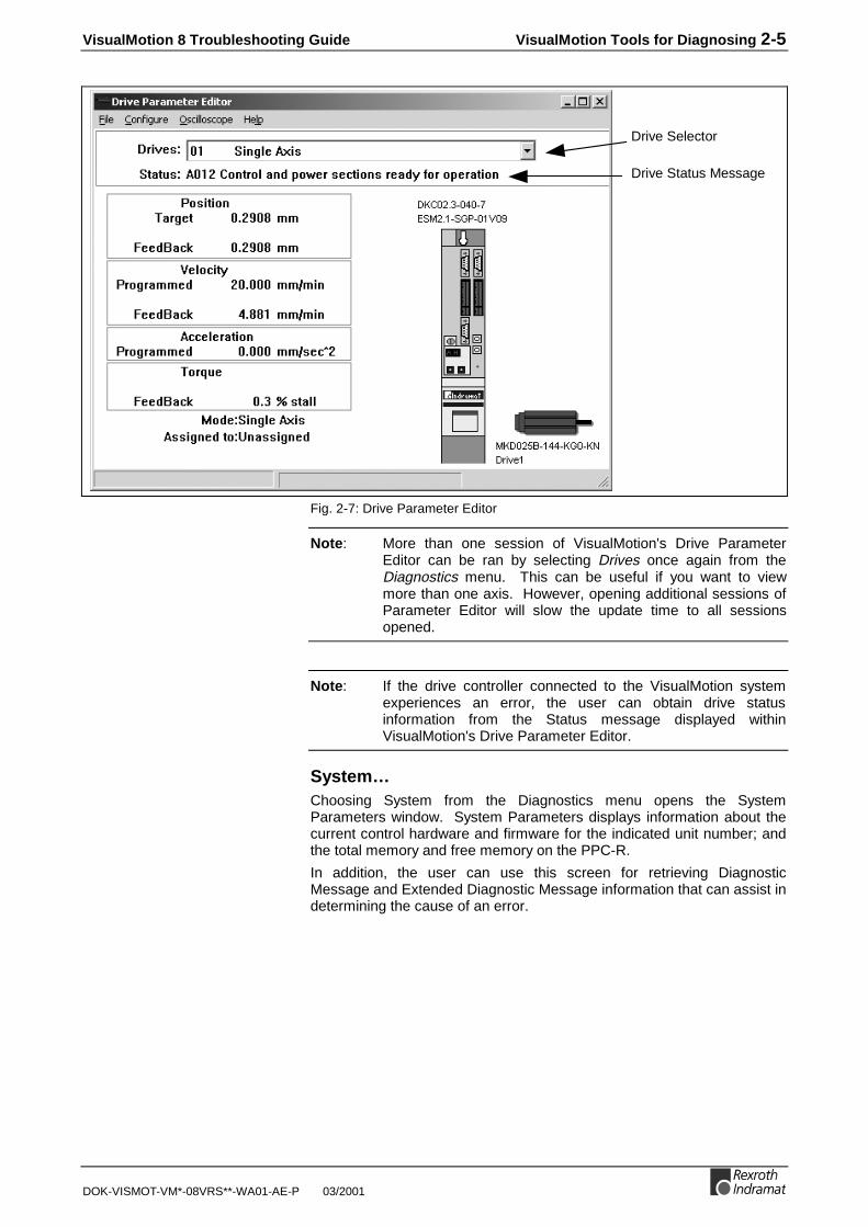
423 Unimplemented InstructionCause:
The command instruction or icon is not recognized by the current versionof GPP firmware or VisualMotion Toolkit software. Example: A new iconfunction is used with older card firmware. The icon can be identified byusing the show program flow <F7> function.
Remedy:Recompile the program without the instruction indicated by the currentinstruction pointer or update the firmware or VisualMotion software.Contact Indramat for updated firmware and software information.
425 Instruction Error: see Task # diag.Cause:An error has occurred in a user program instruction. A more specificmessage is displayed in the diagnostic message for the task (A-D) inwhich the error occurred (T-0-0122). This error usually applies tocoordinated motion instructions.
Remedy:Verify that the following icons are setup properly and do not containvariables with negative values or incorrect axis numbers.
Wait ELS mode ELS Stop
Text message
426 Drive D is not readyCause:Programmed motion was commanded to axis D before the drive wasenabled (AF).
Remedy:1. Clear error and wait for drive to be enabled before commanding
motion.
2. Check the axis disable bit in AxisD_Control register under On-LineData ⇒ Registers . If the bit is high (1), the drive is disabled.Change the state to low and restart program.
3. Check the fiber optic connections and power to drive.

VisualMotion 8 Troubleshooting Guide Monitoring and Diagnostics 3-19
DOK-VISMOT-VM*-08VRS**-WA01-AE-P 03/2001
427 Calc: invalid table index DCause:1. In a user program calculation expression, the index to a point or event
table is invalid.
2. A value used in the calculation expression is not accounted for in thesizing icon. The value is either greater than or less than the allowablerange. The allowable range is 0 to maximum number entered.
Remedy:1. Locate the Calc icon with the error, if more than one is used, by using
program flow <F7>.
2. If the value in the Calc icon is incorrect, change it to an allowablevalue and clear the error.
3. Verify that the Sizing icon is accounting for all variables, points,events and zones programmed in the user program.
428 Calc: division by zeroCause:In a user program calculation instruction, an attempt was made to divide anumber by zero.
Remedy:1. Locate the Calc icon with the error, if more than one is used, by using
program flow <F7>.
2. Modify the Calc icon and remove any zero expression to thedenominator. The denominator can be expressed as an integer or avariable.

3-20 Monitoring and Diagnostics VisualMotion 8 Troubleshooting Guide
03/2001 DOK-VISMOT-VM*-08VRS**-WA01-AE-P
429 Calc: too many operandsCause:In a user program calculation instruction, too many operands (+, -, *, /,etc.) and operators were used in the string. Use the show program flow<F7> function to locate the Calc icon containing the error.
Remedy:Split the calculation operation using more than one Calc icon inconsecutive order.
430 Calc instruction: invalid operatorCause:An invalid arithmetic operator was found in a user program calculationinstruction. The operator used is not supported by the current version ofVisualMotion Toolkit.
Remedy:Check the compiler and firmware version numbers, and call Indramatservice for assistance in upgrading software. Version information can befound for menu selection Diagnostics ⇒ System.
431 Calc error: see Task A diag.Cause:An error has occurred in a user program calculation instruction.
Remedy:See the task diagnostic message for a communication error message.
432 Calc: too many nested expressionsCause:In a user program calculation instruction, more than 16 operations werepending. See the diagnostic message for each task to find the task andthe instruction.
Remedy:Check the number of operands in the expression, looking for unbalancedparentheses or incomplete expressions.
433 Setup instruction outside of a taskCause:
The following commands must be placed in a task's main program:TASK/AXES, KINEMATIC, and DATA/SIZE. This error is issued if any ofthese commands is found in a subroutine.
Remedy:Move the instructions to Task A, B, C, or D, following the TASK/STARTinstruction or Axis Setup icon.

VisualMotion 8 Troubleshooting Guide Monitoring and Diagnostics 3-21
DOK-VISMOT-VM*-08VRS**-WA01-AE-P 03/2001
434 Axis D configured more than onceCause:
Axis D was selected more than once in a TASK/AXES command
icon.
Remedy:Modify the program so that the axis is selected once.
435 Axis D not assigned to a taskCause:
Axis D was not assigned to the task using the Axis icon but was
specified in a command.
Remedy:Modify the program so that the axis is selected and configured for thecorrect axis number or variable label used in the program.
436 General Compiler Error: XXXXCause:
An error was found in a compile-time instruction (TASK/A XES,KINEMATIC) after program activation.
Remedy:See the task diagnostic message for a description under menu selectionDiagnostics ⇒ Tasks . If there is no task diagnostic message, callIndramat for assistance.
438 Invalid Axis Selected: DCause:
Axis D was not found on the SERCOS ring or is an invalid axis number.This error is issued during single-axis or ELS motion commands.
Remedy:Check the constant or variable that contains the axis number.

3-22 Monitoring and Diagnostics VisualMotion 8 Troubleshooting Guide
03/2001 DOK-VISMOT-VM*-08VRS**-WA01-AE-P
439 Axis #: Invalid Motion TypeCause:The axis type does not match the type of motion used by the instruction.This error is issued when a single-axis command is given to acoordinated motion axis.
Remedy:Locate the icon containing the error and verify that the axis type matchesthe motion type. For example: a coordinated VisualMotion programcontains an axis setup icon that was originally setup for single-axis.
440 I-O Transfer Error: see task diag.Cause:An error occurred in a command instruction selecting a register to write toor to read from. Some examples would be….
Setting an I/O register, I/O Transfer or any other instruction that directlywrites to a register.
Remedy:Locate the instruction icon using show program flow <F7> and verify theregister read and write command.
450 Event D: invalid event typeCause:The event type selected in the event table is not valid or does not matchthe type of motion or event. This error is also issued if an event/trigger(event arm) is executed for a motion-based event.
Remedy:
Make sure that the event type selected under On-Line Data ⇒ Events isconsistent with the type of motion specified for the axis. Modify thenumbered event and correct the event type. Save, compile and downloadthe program.

VisualMotion 8 Troubleshooting Guide Monitoring and Diagnostics 3-23
DOK-VISMOT-VM*-08VRS**-WA01-AE-P 03/2001
451 Invalid event number DCause:The event number is not within the bounds selected with the data/sizecommand for this task.
Remedy:1. Verify that the sizing icon contains the correct amount of events for
the program.
2. Verify that the correct event number is selected and configured fromwithin On-Line Data ⇒ Events.
452 More than D event timers armedCause:Only 'D' repeating timer events can be armed at one time.
Remedy:Check the program flow to make sure that triggered events are beingdisabled.
453 Homing param. transfer error: DCause:
A SERCOS communication error occurred during a drive-controlledhoming command. 'D' indicates the communication error code returnedby the drive.
Remedy:Try homing the axis again. If this error still occurs, call Indramat Servicefor assistance.
454 Axis D homing not completeCause:The drive did not successfully complete the homing sequence.
Remedy:See the drive diagnostics for a status or error message. This can beviewed under Diagnostics ⇒ Drives .

3-24 Monitoring and Diagnostics VisualMotion 8 Troubleshooting Guide
03/2001 DOK-VISMOT-VM*-08VRS**-WA01-AE-P
459 Axis D target position out of boundsCause:
The programmed position in an axis/move command or the Move
icon exceeds the drive's travel limits.
Remedy:1. Adjust the travel limits or check the variable or constant containing
the position. Drive travel limits are programmed in SERCOSparameters S-0-0049, Positive position limit value and S-0-0050,Negative position limit value. Check variable values under On-LineData ⇒ Variables .
2. Check travel limits set in Drive Parameter Editor.
⇒ Select Diagnostics ⇒ Drives from VisualMotion Toolkit's mainmenu.
⇒ Select Configure ⇒ Drive Limits from the Drive Parameter Editorscreen.
460 Invalid program D from binary inputsCause:The program selected from the Binary Program Select bits 9-12 inSystem register 1 does not exist on the card or is greater than themaximum number of programs.
Remedy:Make certain that the program number being selected is available on thecontrol. Program number can be viewed using VisualMotion andselecting Build ⇒ Program Management .
463 Ratio command: invalid ratioCause:In the RATIO command, one of the factors is too large or the masterfactor is zero. The values entered in the Turns field are not correct.
Remedy:Update the ratios so that the master is not a zero and the values are nottoo large.

VisualMotion 8 Troubleshooting Guide Monitoring and Diagnostics 3-25
DOK-VISMOT-VM*-08VRS**-WA01-AE-P 03/2001
464 Can't activate while program runningCause:A new program cannot be activated through the Binary Program Selectinputs, bit 8 of register 1, unless the program is stopped.
Remedy:Stop the currently running program by setting register 1 bit 8 to 0. Set thedesired program number in binary format through bits 9-12 and activatethe new program by setting bit 8 to 1.
465 Drive D config. error, see ext. diag, or465 Drive D: telegram type not supported (versions before 01.20)
Cause:
Drive D does not support a product-specific option or a drive configurationcalculation has failed. Product-specific options include ELS, single-axismotion, or I-O cards.
Remedy:1. The extended diagnostic describes the error in more detail. It often
shows the parameter that failed along with a short messagedescribing the error. If it indicates that a parameter is invalid or aconfiguration is not supported, check the axis configuration with thedrive hardware or software.
2. If the extended diagnostic indicates an error such as ‘Handshaketime-out’ or ‘Drive is not responding’, the SERCOS ring may havebeen disconnected during initialization. Check the fiber opticconnections and the addresses of the drives on the ring.

3-26 Monitoring and Diagnostics VisualMotion 8 Troubleshooting Guide
03/2001 DOK-VISMOT-VM*-08VRS**-WA01-AE-P
467 Invalid ELS Master OptionCause:An option in the ELS/INIT command is invalid, not supported, orinconsistent with the other options. VisualMotion is initialing all of the ELSaxes in the program and has come across an axis parameter A-0-0004option that is invalid
Remedy:Search the program for the axis in fault and verify that the axis options inparameter A-0-0004 are correct and within range. Refer to theVisualMotion 8 Functional Description for an explanation of axisparameter A-0-0004.
468 ELS adjustment out of boundsCause:The phase offset or fine ratio adjustment exceeded the bounds allowed bythe drive. The fine adjust must be between -100 and 300%.
Remedy:Use the show program flow <F7> function to find the ELS phase adjust orCam phase adjust icon in fault. Correct the value entered in degrees,percentage, or the variable if programmed using variables.
CamPhase
ELS PhaseAdjust
470 Axis D velocity > maximumCause:The velocity programmed for axis D exceeds the maximum velocityparameter A-0-0020.
Remedy:Change the velocity value programmed in the velocity icon or the variablelabel being used in the velocity icon to a value less than parameterA-0-0020.
474 Drive D cyclic data size too largeCause:Too much data is configured in the SERCOS cyclic telegram. The drivescurrently support up to 16 bytes of configurable data.
Remedy:Remove I/O or registration options from the parameter or programconfiguration.
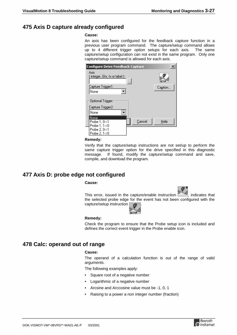
VisualMotion 8 Troubleshooting Guide Monitoring and Diagnostics 3-27
DOK-VISMOT-VM*-08VRS**-WA01-AE-P 03/2001
475 Axis D capture already configuredCause:An axis has been configured for the feedback capture function in aprevious user program command. The capture/setup command allowsup to 4 different trigger option setups for each axis. The samecapture/setup configuration can not exist in the same program. Only onecapture/setup command is allowed for each axis.
Remedy:Verify that the capture/setup instructions are not set/up to perform thesame capture trigger option for the drive specified in this diagnosticmessage. If found, modify the capture/setup command and save,compile, and download the program.
477 Axis D: probe edge not configuredCause:
This error, issued in the capture/enable instruction , indicates thatthe selected probe edge for the event has not been configured with thecapture/setup instruction .
Remedy:Check the program to ensure that the Probe setup icon is included anddefines the correct event trigger in the Probe enable icon.
478 Calc: operand out of rangeCause:The operand of a calculation function is out of the range of validarguments.
The following examples apply:
• Square root of a negative number
• Logarithmic of a negative number
• Arcsine and Arccosine value must be -1, 0, 1
• Raising to a power a non integer number (fraction)

3-28 Monitoring and Diagnostics VisualMotion 8 Troubleshooting Guide
03/2001 DOK-VISMOT-VM*-08VRS**-WA01-AE-P
Remedy:Use show program flow <F7> feature to locate Calc icon with error andcorrect. If variables are being use to represent a value, correct thevariable value from within On-Line Data ⇒ Variables .
481 Event D is already armedCause:An event that is currently armed has been armed again usingevent/trigger (event arm.
Remedy:Check the program for all instants of the specified event number and onlyallow the event to be armed only once.
482 Checksum Error in ProgramCause:The currently active program’s checksum doesn’t match the checksumthat is stored in memory. This indicates that a system error has causedthe control to overwrite memory. Call Indramat service for assistance.
Remedy:Reinitialize VisualMotion Toolkit and reopen the file containing the activeprogram. If no changes were made to the currently active program, save,recompile and download the program.
483 Parameter Init. Error: see Task A diagThere is an error in the parameter initialization or bit initializationinstruction; which is executed when exiting parameter mode. Theparameter format, parameter number, or stored value may be invalid.
A communication error message is displayed in the diagnostic messagefor the task (A-D) in which the error occurred (T-0-0122). Information onthe actual parameter number that caused the error is provided inextended diagnostics (C-0-0124).
Cause:In many cases, this error is issued when a drive is not on the ring or thedrive parameter is not found for a type of drive.
Remedy:1. Make sure that all drives on the ring are powered up and enabled.
2. Check fiber optic connections.
484 Control SYSTEM ERRORCause:This error indicates a problem in the control executive firmware.

VisualMotion 8 Troubleshooting Guide Monitoring and Diagnostics 3-29
DOK-VISMOT-VM*-08VRS**-WA01-AE-P 03/2001
Remedy:See the extended diagnostics parameter (C-0-0124) for more informationor select Diagnostics ⇒ System within VisualMotion Toolkit, and call theIndramat service department for assistance.
486 SERCOS Device D is not a driveCause:
The SERCOS device with address D was enabled in the user program orparameterized as an axis, but an I-O slave or other type of slave wasdetected.
Remedy:Check the VisualMotion program for any instances where the device (nota drive, but maybe an I/O station) number is being configured as a driveand modify the program accordingly. Once corrected, Save, Compile andDownload the modified program.
487 Cam D is invalid or not storedCause:In the CAM/activate command, the selected CAM (‘D’) is not stored on thecard or does not contain valid data.
Remedy:Check the variable or constant that selects the CAM. Check that there isa valid CAM with index ‘D’ stored on the control.
488 Cam Error: See Task # diag.Cause:An error was issued during a CAM command in task (A-D).
Remedy:See the task diagnostic message (T-0-0122) for a description. See theextended message under Diagnostics ⇒ Tasks for more information.
489 More than D CAM axes selectedCause:The control limits the number of axes configured as control Cam Axes to‘D’. The maximum number of control CAMs allowed on the card is 8.The maximum number of control CAMs running in the program is 4.
Remedy:Check the program and modify it so that the number of control CAMsrunning is less than the number specified in this diagnostic message.

3-30 Monitoring and Diagnostics VisualMotion 8 Troubleshooting Guide
03/2001 DOK-VISMOT-VM*-08VRS**-WA01-AE-P
490 System Memory Allocation ErrorCause:The dynamic memory space on the control has been exhausted. Thisdiagnostic message is related to the amount of memory consumed by thecompiled program as well as operations being performed dynamically,such as index CAM builds. The amounts of configured memory in thesizing icon directly effect the amount of system memory available.
Remedy:1. The amount of memory available in the system can be viewed under
menu selection Diagnostics ⇒ System . One way to decreasememory usage would be to verify that all the items being selectedwithin the sizing icon are necessary. For example: if only 3 eventfunctions are used in the current VisualMotion program but 10 eventsare reserved in memory within the sizing icon, then the addition 7events use up unnecessary memory resources. Decrease each fieldwithin the sizing icon to free up memory space.
2. If the problem persists, contact Indramat Service for assistance.
492 Programs were lostCause:User programs and data were lost. The RAM backup battery has failed,the firmware was upgraded, or an internal system error has corrupted thememory.
Remedy:1. Replace the battery and/or upload the archive file under Commission⇒ Archive .
2. Use control register 001 bit 1 to set control in and out of parametermode. Then, use the archive function under the file menu inVisualMotion Toolkit to restore the system.
493 Data was restored from FlashCause:User programs and parameters have been restored from Flash EPROM.
Remedy:1. If the card has just been installed in the VME rack and a valid
program is active, clear this error and proceed.
2. If the card has not just been installed, this indicates that the VMEstandby battery has failed and the previous program and data hasbeen replaced with that stored in Flash.
494 Sequencer init. error: see task T diagCause:An error has occurred in a sequencer/initialize instruction in task ‘T’. Thetask diagnostic (T-0-0122) and the extended diagnostic (C-0-0124) givesa more detailed description of the error. This error occurs when thesequencer is commanded to initialize. Refer to Sequencer in theVisualMotion Reference manual for more information.

VisualMotion 8 Troubleshooting Guide Monitoring and Diagnostics 3-31
DOK-VISMOT-VM*-08VRS**-WA01-AE-P 03/2001
This error can occurin both initializingoptions.
Remedy:1. One possibility is that an Event is programmed as a function in the
sequencer icon. Modify the program and replace the event with asubroutine.
2. Task diagnostic can be view under Diagnostics ⇒ Tasks
3. Extended diagnostic can be view under Diagnostics ⇒ System
495 Sequencer error: see task T diag.Cause:An error has occurred in a sequencer/execute instruction in task ‘T’. Thetask diagnostic (T-0-0122) and the extended diagnostic (C-0-0124) givesa more detailed description of the error. This error occurs when thesequencer is commanded to execute. Refer to Sequencer in theVisualMotion 8 Functional Description for more information.
This error can occurwhen a sequencer isbeing executed.
Remedy:1. One possibility is that an Event is programmed as a function in the
sequencer icon. Modify the program and replace the event with asubroutine.
2. Task diagnostic can be view under Diagnostics ⇒ Tasks.
3. Extended diagnostic can be view under Diagnostics ⇒ System.
496 Can't Execute this Instruction from an EventCause:This user program instruction cannot be executed from within an event.See the task error descriptions and the current program instruction.Some operations, such as sequencer initialization, cannot take placeduring an event.
Remedy:Move the instruction into a main user task or subroutine.

3-32 Monitoring and Diagnostics VisualMotion 8 Troubleshooting Guide
03/2001 DOK-VISMOT-VM*-08VRS**-WA01-AE-P
497 Limit switch config. error, see ext. diagCause:This error is issued at activation of a program when one of the PLSparameters defined in the program is invalid. It is also issued when theELS setup is incorrect for PLS operation.
Remedy:1. Parameter C-0-0124 provides a detailed description of the error as an
extended diagnostic message.
2. Extended diagnostic can be view under Diagnostics ⇒ System.
498 Drive D Shutdown WarningCause:This error is issued when any drive has a Class 2 shutdown warning. Thetasks that stop for errors switch into manual mode and perform acontrolled stop of all axes. A drive warning indicates a condition that willlater cause a shutdown, but is serious enough to require immediateattention.
Note: Class 2 warnings may not be detected by the control if driveparameter S-0-0012 is being continuously read by the userinterface or user program, since the diagnostic change bit isreset whenever this parameter is read.
Remedy:1. Since the warning may have already been cleared on the drive, the
extended diagnostic (C-0-0124) latches the class 2 diagnostic bits(drive parameter S-0-0012) from the drive so that this condition canbe corrected.
2. Extended diagnostic can be view under Diagnostics ⇒ System.
3. Using VisualMotion Toolkit, open the Drive Parameter Editor undermenu selection Diagnostics ⇒ Drives and view the status line for adescription of the drive error. Refer to the drive manual for moreinformation.
499 Axis number D not supported in this versionCause:This version of control firmware is limited to less than D axes. The axisnumber is limited to the number of axes allowed. Currently, VisualMotionallows 32 axes.
Remedy:Check the program for an axis value greater than 32 or a variable labelgiven to an axis with a value greater than 32.
500 Axis D is not referencedCause:Axis D has not been homed, the reference position has not been set, orthe reference position has been lost. The reference position bit in driveparameter S-0-0403 is zero. To enable or disable this error, use

VisualMotion 8 Troubleshooting Guide Monitoring and Diagnostics 3-33
DOK-VISMOT-VM*-08VRS**-WA01-AE-P 03/2001
parameter A-0-0006. If parameter A-0-0006, bit 1 is set to (1), thenVisualMotion will display this error.
Remedy:1. Stop the VisualMotion program. Recycle the program by switching to
manual mode and then back to auto mode. This process willreinitialize the program back to the Start icon. If the homingcommand instruction is at the beginning of the program, re-start theprogram to home the axis again.
2. Verify homing options within the Drive Parameter Editor.Diagnostics ⇒ Drives ⇒ Configure ⇒ Drive Reference
3. If the drive controlled homing procedure still does not occur, contactIndramat Service for assistance.
501 Drive D comm. error, see ext. diag.Cause:An error in drive communications has occurred while the control wasreading or writing a service channel parameter for an internal operation.
Remedy:
Parameter C-0-0124, extended diagnostics, has a detailed description ofthe error. This extended diagnostic can also be using VisualMotionToolkit under menu selection Diagnostics ⇒ System .
502 ELS and CAMs not supported in this versionCause:The ELS and CAM features in the currently active VisualMotion programare not supported in this version of GPP firmware.
Remedy:The control contains a firmware version that is not capable of performELS and Cam functions. Verify the version of firmware in controlparameter C-0-0100 or using VisualMotion Toolkit under menu selectionDiagnostics ⇒ System . Contact Indramat Service for assistance.
504 Communication TimeoutCause:During a timed serial port transmission, the serial port has not respondedwithin the time set in parameter C-0-0016. Timed transmissions are usedfor jogging through VisualMotion.
Remedy:
If this error occurs, increase the timeout value in C-0-0016.
Using VisualMotion Toolkit, select On-Line Data ⇒ Parameters from themain menu. Refer to Parameters, for instructions.

3-34 Monitoring and Diagnostics VisualMotion 8 Troubleshooting Guide
03/2001 DOK-VISMOT-VM*-08VRS**-WA01-AE-P
505 Axis D is not configuredCause:A user program command was issued to Axis D, but axis D is notconfigured in the program.
Remedy:Modify the user program so that the correct axis is addressed, or excludethe axis from the system using Axis parameter A-0-0007.
506 I-O Mapper initialization errorCause:The I-O Mapper was invalid at initialization, due to loss of memory or anincompatibility in the Mapper version. During the initial system setup anI/O Mapper file should have been created and saved with the extension*.iom .
Remedy:
1. Reinstall the I/O Mapper file ( *.iom ) using the following VisualMotionToolkit procedure.
Note : Qualified trained personnel who can verify that the I/O Mapperfile being selected is the correct file for the system should onlyperform this procedure.
2. Select Commission ⇒ I/O Mapper.3. From the Ladder Editor screen, select File ⇒ Get Ladder from
control.4. Once the I/O Mapper file is loaded, the I/O Mapper strings can be
viewed and verified by selecting Windows ⇒ Boolean Equations .5. Once verified, select File ⇒ Send Ladder to control and answer
“Yes” to the popup window warning.6. Reinitialize the VisualMotion program and test I/O Mapper.
Note : If the *.iom file does not upload from the control, use File ⇒Open from the Ladder Editor screen and open a valid *.iomfile.
7. If the error is still encountered, contact Indramat Service forassistance.
508 User Watchdog TimeoutCause:The user watchdog timer enforces a time constraint on a user task or auser interface.
Every time a nonzero timeout value is written to C-0-0021, a timer istriggered on the control. If the timeout expires, the error "508 UserWatchdog Timeout " is issued. The timer is checked by the control every50ms.If C-0-0021 is set to zero, the watchdog timer is disabled. If it is nonzero,it is active when the control is in run mode, there are no errors, and thetask specified in C-0-0022 is running.In a user program task, parameter C-0-0021 can be written to via aparameter transfer at the beginning of the main processing loop. If theVisualMotion system tasks or the user program events are consuming toomuch processor time, the time set in C-0-0021 will elapse, and error 508will be issued. The programmer can then adjust the timing of the events,

VisualMotion 8 Troubleshooting Guide Monitoring and Diagnostics 3-35
DOK-VISMOT-VM*-08VRS**-WA01-AE-P 03/2001
or increase the SERCOS or I/O cycle times to allow more time for theuser task.
Remedy:1. If this feature is intentionally set and the user's desired elapse time,
programmed in parameter C-0-0021, can be increased, the user canmodify the value in parameter C-0-0021.
2. If this feature is not desired but a value other than zero appears inparameter C-0-0021, change this value to zero to disable this feature.
509 Control System Timing Error DCause:When the control is powered up, a timer monitors high-level control taskand generates this error if the system timing overlaps.The cause for timeout can also result from electromagnetic interferenceon serial communications.
Remedy:
1. The default SERCOS cycle time is 2000µsec. Applications thatrequire multiple functionality, such as coordinated motion usingFieldbus interface across serial communications, should double thevalue of control parameter C-0-0099 (SERCOS Cycle Time). Switchthe system in and out of parameter mode to update the SERCOSring.
2. If the increase in SERCOS Cycle Time does not help, contactIndramat Service for assistance.
3. Replace the Serial Communication cable.
514 Control SYSTEM ERROR DCause:This diagnostic has resulted from a processing error in the main controlprocessor. It can be triggered by numerous types of program instructions.
Remedy:1. Cycle power to the entire VisualMotion system and reestablish
communications between VisualMotion Toolkit and the control.
2. Verify that all system communications under the Setup menu arecorrect.
3. Verify that the DDE Server is functioning and communicating.
515 PLC Communications ErrorCause:After initialization, GPP monitors the PLC's heart beat by means of aninternal life counter. GPP reads the life counter value every SERCOScycle and compares it to the previous value. This error is issued if the lifecounter value does not change after 10 cycles.
Remedy:Cycle power to the entire VisualMotion system and reestablishcommunications between the PLC and the control.

3-36 Monitoring and Diagnostics VisualMotion 8 Troubleshooting Guide
03/2001 DOK-VISMOT-VM*-08VRS**-WA01-AE-P
516 More than D registration mark limit exceededCause:The maximum of 4 registration instructions has been exceed in the activeVisualMotion program. Up to 4 axes can use the registration function atany one given time. This error will be issued at compile time.
Remedy:Make certain that the active VisualMotion program is only using themaximum of 4 registration instructions.
519 Lost Fieldbus ConnectionCause:A Lost Fieldbus connection is issued when cyclic communicationsbetween the slave and master fieldbus interfaces are no longer present.This message is issued when register 19 bit 4 transitions from high (1) tolow (0). The error is hardware related as is normally caused by…
• a bad or disconnected cable.
• a hardware related problem with the Fieldbus interface on the control.
Note: Shutdown message 519 is only issued while in phase 4 if theFieldbus Error Reaction in the Fieldbus Slave Configurationwindow for GPP.
Remedy:1. Check and verify all cable connects between the slave and master
Fieldbus connections.
2. Contact Indramat Service for assistance.
520 Fieldbus mapping timeoutCause:The Fieldbus Mapper continually scans the system for sufficientresources to process the cyclic data mapping list (2600-list). If 10 out of10 attempts of the mapping list update are missed, the system isconsidered to have insufficient resources. Error 520 Fieldbus MapperTimeout is generated if the selected error reaction is set as "Shutdown(default)," (Parameter C-0-2635), in the Fieldbus Slave Configurationwindow. Motion to all axes will stop based on the selected error reactionat each drive.

VisualMotion 8 Troubleshooting Guide Monitoring and Diagnostics 3-37
DOK-VISMOT-VM*-08VRS**-WA01-AE-P 03/2001
Remedy:PPC controls currently run the fieldbus mapper at a fixed 8ms SERCOSscan time. If this error occurs, contact Indramat Service for assistance.
521 Invalid Virtual Master ID: %dCause:This diagnostic is displayed if a ID number other than 1 or 2 is used toidentify a Virtual Master. The selection of Virtual Master ID number otherthan 1 or 2 is only possible if written in text code language outside ofVisualMotion Toolkit.
Remedy:Verify that the correct ID number (1 or 2) is programmed when referring toa Virtual Master.
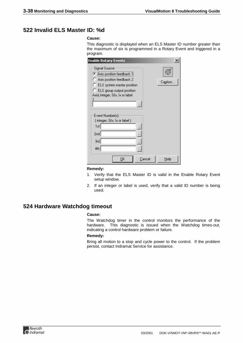
3-38 Monitoring and Diagnostics VisualMotion 8 Troubleshooting Guide
03/2001 DOK-VISMOT-VM*-08VRS**-WA01-AE-P
522 Invalid ELS Master ID: %dCause:This diagnostic is displayed when an ELS Master ID number greater thanthe maximum of six is programmed in a Rotary Event and triggered in aprogram.
Remedy:1. Verify that the ELS Master ID is valid in the Enable Rotary Event
setup window.
2. If an integer or label is used, verify that a valid ID number is beingused.
524 Hardware Watchdog timeoutCause:The Watchdog timer in the control monitors the performance of thehardware. This diagnostic is issued when the Watchdog times-out,indicating a control hardware problem or failure.
Remedy:Bring all motion to a stop and cycle power to the control. If the problempersist, contact Indramat Service for assistance.

VisualMotion 8 Troubleshooting Guide Monitoring and Diagnostics 3-39
DOK-VISMOT-VM*-08VRS**-WA01-AE-P 03/2001
525 I/O Configuration error, see extended diagnosisCause:
This diagnostic is displayed when the I/O User Configuration C-0-2017does not match the actual I/O configuration on the machine (Visible I/OStations, C-0-2013). The I/O User Configuration is compared to theactual I/O configuration during initialization of the control, and whenswitched in and out of parameter mode. When the control switches fromSERCOS phase 2 to phase 3 and a change has occurred in the I/Oconfiguration, due to a replacement, modification or hardwarecommunication failure, a 525 I/O Configuration error is issued. Thisdiagnostic can also occur after downloading an invalid I/O UserConfiguration to the control, for example, configuring an I/O module ordrive number that does not exist on the machine.
Remedy:1. Since many areas of an I/O configuration can cause an error, refer to
the extended diagnosis for detailed information as to the root cause ofthe problem.
2. To view extended diagnostics using VisualMotion Toolkit, selectDiagnostics ⇒ System . Extended diagnostic text is displayed at thebottom of the window.
526 SERCOS Multiplex Channel Configuration, see ext. diagCause:The SERCOS multiplex channel will be enabled by either the selection ofthe Drive PLS Fast Write feature or the detection that the AT or MDT hasexceeded the 16-byte limit. 526 SERCOS Multiplex Channel Config,see ext. diag is followed by one of the following extended diagnostics(examples: D%d = D01 for Drive 01, %s = S-0-0258). Extendeddiagnostics can be viewed by selecting Diagnostcis ⇒ System inVisualMotion Toolkit.
• D%d: Ident %s not supported in S-370Through Parameters A-0-0180..182, a parameter was entered whichis not supported by the SERCOS MDT Multiplex Channel.
• D%d: Ident %s not supported in S-371Through Parameters A-0-0185 and 186, a parameter was enteredwhich is not supported by the SERCOS AT Multiplex Channel.
• D%d: Probe not allowed in Single Axis ModeWith the SERCOS Multiplex Channel enabled, the Probe option is notavailable in Single Axis mode.
• D%d: Multiple probe idents in telegramWith the SERCOS Multiplex Channel enabled, only one probe ident isallowed in the multiplex channel.
• D%d: PLS Idents cannot be entered directly by userThe PLS Fast Write feature, A-0-0004 bit 8 set, automaticallyaddresses the necessary idents for PLS write in the SERCOSMultiplex Channel.
• Maximum Quantity of Multiplex Drives ExceededThe limit of how many drives the GPP control can support with theSERCOS Multiplex Channel enabled has been exceeded.

3-40 Monitoring and Diagnostics VisualMotion 8 Troubleshooting Guide
03/2001 DOK-VISMOT-VM*-08VRS**-WA01-AE-P
527 Control Initialization Error, see ext. diagCause:527 Control Initialization Error, see ext. diag is related to error 526 and isfollowed by the following extended diagnostics (examples: D%d = D01 forDrive 01, %s = S-0-0258). Extended diagnostics can be viewed byselecting Diagnostics ⇒ System in VisualMotion Toolkit.
• D%d: Ident %s is not supported in cyclic channelAn ident was selected that has a variable length.
528 System Event %d OccurredCause:This diagnostic can only be viewed using VisualMotion's diagnostic log. Itmonitors status information and also functions as a debugging log forunexpected firmware errors related to the File System. The File Systemconsists of…
• Downloaded VisualMotion user programs # 1-10,
• I/O Mapper (C-0-3000),
• Fieldbus object mapping list 2600 and 2700,
• I/O User Configuration (C-0-2017),
• Control CAMs # 1-37.
Remedy:If system problems result due to lost parameters within the File Systemand this diagnostic is found within the Diagnostic Log, contact IndramatService for assistance.
529 Invalid ELS Group ID: %dCause:This diagnostic is displayed when an ELS Group ID number greater thanthe maximum of eight is programmed in a Rotary Event and triggered in aprogram.
Remedy:1. Verify that the ELS Group ID is valid in the Enable Rotary Event setup
window.
2. If an integer or label is used, verify that a valid ID number is beingused.

VisualMotion 8 Troubleshooting Guide Monitoring and Diagnostics 3-41
DOK-VISMOT-VM*-08VRS**-WA01-AE-P 03/2001
530 Cam # is active, can't overwriteCause:This error is displayed during Phase 4 (automatic mode) initialization andis a result of trying to assign an already active CAM number to a newbuild.
Remedy:Make sure the selected CAM number for the new build is unique in theactive VisualMotion program.
531 Invalid variable for Fieldbus MappingCause:In order for Fieldbus Mapping list to function properly, all cyclic and non-cyclic program variables (floats, integers) used in the Fieldbus Mappermust match existing program variable in the VisualMotion user program.This error is issued when activating a different VisualMotion programcontaining program variables that are invalid in the current Fieldbusmapping list.
Remedy:1. Make the appropriate program variable modifications in the
VisualMotion user program that correspond to the program variablesused in the current Fieldbus Mapping list.
2. If the VisualMotion user program contains the desired programvariables, then make the appropriate modifications to the FieldbusMapping list or load a different Fieldbus Mapping list in the FieldbusMapper.
532 Power fail brown out condition detectedCause:The PPC-R hardware trigger interrupt has detected a drop in powercausing a brown out condition. If the condition is not corrected within 2seconds, the control shuts/down and the error is logged in the Diagnosticlog. All motion to slave axis will stopped based on the selected errorreaction in each drive.
Remedy:This error can be cleared by pressing the S2 reset button found below thePSM memory card on the PPC-R.
533 Multiple instances of index CAM: #Cause:A CAM Indexer can be assigned to any ELS Group or to any slave axiswithin an ELS Group as long as the same CAM Indexer is not used morethan once. This error is issued when the active VisualMotion programencounters a CAM Indexer that is already being used somewhere else inthe program.
Remedy:Verify that the current VisualMotion program is not using the same CAMIndexer number in more than one instance.

3-42 Monitoring and Diagnostics VisualMotion 8 Troubleshooting Guide
03/2001 DOK-VISMOT-VM*-08VRS**-WA01-AE-P
534 Hardware version not supportedCause:The control has detected an older version of PPC-R hardware(PPC-R0*.1) that is not supported by the current version of GPP firmware.
Remedy:Upgrade your current PPC hardware to a newer version (PPC-R0*.2 orlater) for support of the current GPP firmware. Contact Indramat servicefor assistance.
535 Invalid Conveyor ID: %dCause:A conveyor number outside the allowable range (1-4) was assigned anddownloaded to the control. This error is issued at program activation.
Remedy:Change the conveyor number to an allowable value.
536 Multiple Instance of Conveyor with ID: %dCause:This error is issued at program activation when more than one ConveyorTracker icon is used with the same ID number.
Remedy:Remove one of the Conveyor Tracker icons from the VisualMotionprogram.
537 Conveyor Assigned to an Invalid Axis Number: %dCause:An invalid axis number outside of the allowable range (1-32) wasassigned to the Conveyor Tracker icon.
Remedy:Modify the axis number assigned to the Conveyor Tracker icon.
538 Conveyor Secondary Feedback Invalid for Axis: %dCause:A conveyor was configured to follow an axis with a secondary feedbackdevice but the axis was not configured with a secondary feedback device.A Secondary feedback device is not allowed as an ELS master.
Remedy:Configure the axis to include a secondary feedback device or change theSERCOS drive address to a drive with a secondary feedback device.
539 Invalid Parameter NumberCause:A Procedure command was instructed using the Command Icon with aninvalid parameter number. Allowable procedure command parametersare as follows:
For Control : C-0-2903 and C-0-2905.

VisualMotion 8 Troubleshooting Guide Monitoring and Diagnostics 3-43
DOK-VISMOT-VM*-08VRS**-WA01-AE-P 03/2001
For Drive : A list of allowable drive procedure commands parameters arefound in drive parameter S-0-0025.
Remedy:Modify the parameter used in the Command icon. Next, compile anddownload the user program.
540 External PLS Card errorCause:General error message for PLS card. It will always be accompanied by anextended error message.
Remedy:
Extended Diagnostics C-0-0124 Meaning
002: Command locked xx A command to the PLS card could not be executed dueto current operation. This can happed during phaseswitching.
007: PLS could not synchronize xx The hardware synchronization between the PLS card andthe PPC failed. The SERCOS time must be between 2and 8 ms.
008: Unknown output xx The number for the output is unknown / illegal. Numbermust be in the range of 1 to 32.
012: Offset is larger than resolution xx The offset of the PLS master axis is bigger than itsresolution. Reduce number in C-0-2943.
014: Illegal master axis, see C-0-2941 xx The number of a master for a PLS card master is notvalid. Check entries in parameter C-0-2941.
015: Master axis is not active xx The PLS master axis is used, but this axis is not defined.
018: Run time error occurred xx A software failure occurred on the PLS card.
031: Initialization error on PLS The PLS card could not initialize
032: Synchronization error The PLS card software could not synchronize to thePPC.
0yy: Maximum PLS speed exceeded at axis zz The maximum speed of 3500 RPM had been exceeded.yy is an error number between 33 and 40; zz is the PLSmaster axis number which exceeded the speed limit.
041: Cyclic handshake error The software handshake between the PLS and the PPCfailed.
042: PLS internal error The PLS had an unrecoverable error. Power cycle isnecessary.
0yy: General error xx An error happened during the communication betweenPPC and PLS. yy is an error number (1, 4, 5, 6, 10, 16 or17);
Error while parameterize PLS, report number: yy An error occurred during parameterization of the PLScard. This error is mainly related to the PLS hardware.The PLS needs to be recognized by the hardware andfirmware is downloaded and started during power up.Errors can occur during this download. Also if one tries tostart a command (C-0-2903, C-0-2905) on the PLS cardwithout a PLS card being present, than this error will beissued. yy is an error number that specifies the failedoperation.
Parameter Dy.z, code=w, task=PLS evt=0 When the PLS needs to know further information fromdrives it will request the applicable parameter. This errorreflects errors from this request. y references the drivenumber where the error occurred, z the S-parameter andw an internal error code

3-44 Monitoring and Diagnostics VisualMotion 8 Troubleshooting Guide
03/2001 DOK-VISMOT-VM*-08VRS**-WA01-AE-P
Extended Diagnostics C-0-0124 Meaning
063: Wrong encoder type For real drives, only encoder of type 1 (primary encoder)or type 2 (secondary encoder) exists.
Wrong master type See C-0-2940. Masters can only be of type ELS-master(1), ELS-group (2) or drives (3).
065: Switch yy outside position limit Switch number yy is not within the position limits of itsassociate PLS master.
066: Master number > 32 or master not present The PLS master number is either not valid, or the masteris not present in the system. Check C-0-2941.
541 Link Ring Error, see ext. diag.Cause:
When a Link Ring error occurs, the H1 display on the PPC-R will display"541, Link Ring Error ". For detailed information, refer to the extendeddiagnostic message in Table 3-2. Link ring errors are clear with a low-to-high (0-1) transition of Bit 5 in System_Control register 001.
PPC-R H1Display
Diagnostic Code C-0-0123 Diagnostic Message C-0-0122
E541 541 541 Link Ring Error
Table 3-1: Link Ring Diagnostic Code
Extended DiagnosticsC-0-0124
Meaning
Other Link Masteralready active
There is more than on Link Master in the LinkRing.
Link not possible The hardware combination of PPC-R and DAQdoes not permit a control link.
Transmission pathdefective
The link participant has detected a fiber opticcable break in the Link Ring.
Master position fault(MDT)
The transmission of the master axis position bythe Link Master to the link subscriber isexperiencing problems.
Master position fault (AT) The transmission of the master axis position bythe Link Slave to the Link Master is experiencinginterference.
Selected link address notpermitted
The Link Ring address, as set by control’s UnitNumber parameter (C-0-0002), must be between1 and 32.
DAQ: SERCOS interface– ASIC: initialization error
A hardware error occurred during the initializationof the DAQ card.
Table 3-2: Link Ring Extended Diagnostics
542 PLC Cyclic Mapping TimeoutCause:The Fieldbus Mapper continually scans the system for sufficientresources to process the PLC cyclic data mapping list C-0-2600. If 10 outof 10 attempts of the mapping list update are missed, the system isconsidered to have insufficient resources. Error 542 PLC Cyclic MappingTimeout is generated if the selected error reaction is set as "Shutdown(default)," (Parameter C-0-2635), in the Fieldbus Slave Configurationwindow. Motion to all axes will stop based on the selected error reactionat each drive.

VisualMotion 8 Troubleshooting Guide Monitoring and Diagnostics 3-45
DOK-VISMOT-VM*-08VRS**-WA01-AE-P 03/2001
Remedy:PPC controls currently run the fieldbus mapper at a fixed 8ms SERCOSscan time. If this error occurs, contact Indramat Service for assistance.
543 PLC Runtime ErrorCause:This error is issued when the PLC has a fatal error, either hardware orfirmware related.
Remedy:If this error occurs, contact Indramat Service for assistance.
3.5 Communication Error Codes and Messages
!01 SERCOS Error Code # xxxx (xxxx = Error code)This is the code set in the data status word of the drive if SERCOScommunication is invalid. Call Indramat Service if this error occurs.
!02 Invalid Parameter NumberThe requested or sent parameter does not exist on the control or thedrive, or the format of the parameter is incorrect.
!03 Data is Read OnlyThe data in this parameter may not be modified.
!04 Write Protected in this mode/phaseThe data in this parameter can not be written in this mode orcommunication phase. Switch into parameter mode (phase 2) to enterthe parameter.
!05 Greater than maximum valueThe parameter exceeds the maximum allowed value.

3-46 Monitoring and Diagnostics VisualMotion 8 Troubleshooting Guide
03/2001 DOK-VISMOT-VM*-08VRS**-WA01-AE-P
!06 Less than minimum valueThe parameter is less than the minimum allowed value.
!07 Data is InvalidParameter data is invalid, or the format of the parameter is invalid. Seethe drive or control system Parameter Descriptions.
!08 Drive was not foundThe requested drive was not found on the SERCOS ring.
!09 Drive not ready for communicationThe requested drive or the SERCOS ring has not been initialized.
!10 Drive is not respondingThe drive did not respond to a service channel request. Check systemdiagnostics for the state of the SERCOS ring.
!11 Service channel is not openWhen switching between initialization phases, data from the drive ismomentarily invalid, and this message is sent instead of the requesteddata.
!12 Invalid Command ClassA serial port command is invalid or not supported at this time.
!13 Checksum Error: xx (xx= checksum that control calculated)The control detected an invalid or missing checksum in data that was sentto it. As a debugging aid, the checksum that the control calculated on theincoming data is also sent with this message.
!14 Invalid Command SubclassA serial port command option is invalid or not supported.
!15 Invalid Parameter SetThe parameter set number (task or axis) is invalid.
!16 List already in progressAn attempt has been made to start a parameter or program list that isalready in progress.

VisualMotion 8 Troubleshooting Guide Monitoring and Diagnostics 3-47
DOK-VISMOT-VM*-08VRS**-WA01-AE-P 03/2001
!17 Invalid Sequence NumberThe sequence number of a parameter or program list is invalid or hasbeen sent out of order.
!18 List has not startedA parameter or program list has not been initiated (i.e., sequence numberwas sent before list was started).
!19 List is finishedThis is an acknowledgment that a parameter or program list is complete.It does not indicate an error.
!20 Parameter is a ListThis parameter is a variable-length list, and its data cannot be displayedas a normal parameter.
!21 Parameter is not a ListOnly Variable-Length List parameters can use the Parameter Listsequence.
!22 Invalid Variable NumberThe variable mnemonic was not 'I' or 'F', or the variable number is greaterthan the maximum number of variables allocated.
!23 Insufficient Program SpaceThis message is sent after the control receives a "P W" program header ifnot enough contiguous memory is left on the control to store the program.Other programs may need to be deleted or their order rearranged. Checksystem parameters C-0-0091, C-0-0092 and C-0-0093 for systemmemory status.
!24 Maximum number of files exceededThe control allows up to 10 programs resident in the control. This errormessage is sent when the control receives a "PW" program header andthere are already 10 stored programs. One of the control residentprogram files must be deleted to make room to download the program.
!25 Invalid Program HeaderThe format of the program header sent to the control is invalid, or thiscommand is not available for reading or writing.

3-48 Monitoring and Diagnostics VisualMotion 8 Troubleshooting Guide
03/2001 DOK-VISMOT-VM*-08VRS**-WA01-AE-P
!26 Checksum Error in ProgramThis message is sent at the end of a download if the checksum of thedata does not match the checksums sent in the program or programheader.
!27 Invalid Program HandleThe format of the handle is incorrect, or this command is not available forreading or writing.
!28 Function not ImplementedThe function being request is not supported in this version.
!29 Program not found on ControlA program corresponding to the requested program handle was not found(e.g., the program is not resident in the control).
!30 Invalid I/O Register or Bit NumberThe I/O register mnemonic is invalid or a register number greater than themaximum number of registers was sent.
!31 Invalid Table IndexThe ABS, REL, or EVT table name was incorrect, or the index numberwas greater than the maximum number of points or events.
!32 Communication Port ErrorThe serial port receive buffer has overflowed. Make sure communicationis set to half-duplex.
!33 Invalid Data FormatThe format of the data received by the control is invalid (e.g., non-digitsare sent in a decimal number).
!34 Active program can't be deletedThe active program cannot be deleted at any time. To delete an activeprogram, first stop program and then delete.
!35 Parameter mode is requiredThe action requested can only be performed in Parameter Mode.

VisualMotion 8 Troubleshooting Guide Monitoring and Diagnostics 3-49
DOK-VISMOT-VM*-08VRS**-WA01-AE-P 03/2001
!36 Invalid Event NumberThe event number selected in the ABS or REL point table is out of therange of the total number of events.
!37 Invalid Event FunctionThe function name selected in the event table does not exist on thecontrol or is not defined as an event function.
!38 Program file version mismatchThe version of the file system on the control does not match that of thedownloaded file. Upgrade to the latest version of VisualMotion Toolkit.
!39 Can't activate while program runningA new program cannot be activated unless all user tasks are stopped.
!40 No programs are activeNo programs are active on the control. Download a program to the card.
!41 System Error: pSOS #XXXXThis is an internal system error. Call Indramat Service for assistance.
!42 Mapper: invalid operatorAn invalid Boolean operator was found in I/O Mapper when it was sent tothe control.
!43 Mapper: too many operationsThe maximum number of Boolean operations allowed by the control I/OMapper has been exceeded.
!44 Mapper: invalid registerA register exceeds the maximum number of registers or is 0.
!45 Mapper: invalid bit or maskThe bit number or mask sent exceeds 16 bits.
!46 Mapper: register is read-onlyAn assignment to a read-only register or bit was made (e.g., attempting towrite to a control status register).

3-50 Monitoring and Diagnostics VisualMotion 8 Troubleshooting Guide
03/2001 DOK-VISMOT-VM*-08VRS**-WA01-AE-P
!47 Invalid Unit NumberThe unit number (second character in string) is not a number between '1'and 'F' or an ASCII space character.
!50 Invalid Download BlockThe block sent during a program download is incorrect in length or is notin hexadecimal format.
!52 Invalid AxisThe parameter set for the requested axis does not exist. Either this axisis disabled or the control does not support this number of axes.
!53 Waiting for service channelWhen switching between drive initialization phases, data from the drive ismomentarily invalid. This message is sent instead of the requested data.This message will also be issued whenever a service channel transactioncannot be completed. Continue to retry the message until a validresponse is returned.
!54 List or String is too shortThe text string or parameter list is smaller than the minimum lengthallowed by the control or the drive, or the size of a value does not matchthe attributes sent from the drive.
!55 List or String is too longThe text string or parameter list exceeds the maximum length allowed bythe control or the drive, or the size of a value does not match theattributes sent from the drive.
!56 PC Communication Handshake ErrorThe control is not responding to an ASCII message. Check the addressconfiguration on both the PC (config.sys and system.ini) and the control(address jumper switches).
!57 I/O Mapper: Max file size on Control ExceededThe system memory that was allocated for I/O Mapper strings (8Kbytesfor GPP7 and 128Kbytes for GPP8) has been exhausted. Optimize themapping program so that it fits into memory.
!58 Cannot store CAM: already active for axis DCam data cannot be changed unless no axes are currently using it.Deactivate the CAM for axis ‘D’, then send the CAM again.

VisualMotion 8 Troubleshooting Guide Monitoring and Diagnostics 3-51
DOK-VISMOT-VM*-08VRS**-WA01-AE-P 03/2001
!59 SERCOS handshake/busy timeoutThis is an internal error generated by the SERCOS ASIC. Change modesor reset the card. If it happens again, call Indramat Service.
!60 Executable program is too large (ddK)The executable portion of the user program downloaded to the controlexceeds the maximum limit, which is indicated in the message (‘dd’) inkilobytes. Optimize the program and download it again, or update thefirmware to a version that has a larger program limit.
!61 System Memory Allocation ErrorThe dynamic memory space on the control has been exhausted. CallIndramat Service for assistance.
!62 Cam X data is < 0 or greater than 360All values in the x-column (right hand column) of the CAM file sent to thecontrol must be between zero and the modulo value of the master.
!63 X-Column does not start at 0 or end at 360In the CAM file sent to the control, the first point must be zero and the lastpoint must be the modulo value of the master. Check the beginning andend of the CAM file.
!64 Not supported in user prog file version 1.1The requested feature is not present in the file version of the userprogram from which the data was requested or sent. To use this feature,a compiler upgrade is necessary.
!65 Sequencer: invalid sequence (D)The sequence number (D) is zero or is greater than the allocatedmaximum number of sequencers for this program.
!66 Sequencer: invalid step (D)The sequencer step number (D) is zero or is greater than the allocatedmaximum number of steps for this program.
!67 Invalid function number (D)The function number (D) selected for a sequencer step is invalid or refersto a function that does not exist on the card.
3-52 Monitoring and Diagnostics VisualMotion 8 Troubleshooting Guide
03/2001 DOK-VISMOT-VM*-08VRS**-WA01-AE-P
!68 Function D not accessible in a stepThe function referred to with the number (D) cannot be entered in asequencer step. It needs to be declared accessible by the sequencer inthe user program.
!69 Too many functions are used (D)The total number of functions used by all steps exceeds the number (D)allocated for the program in the data sizing instruction, or the number offunctions used in a step exceeds the number of functions remaining.Reduce the number of functions used or allocate more function slots inthe data sizing instruction.
!70 Maximum steps per sequence exceeded (D)The number of steps in a sequence exceeds the number (D) allocated forthe program in the data sizing instruction.
!71 Maximum functions per step exceeded (D)Up to (D) functions can be used in one sequencer step. This is a systemlimit, which in version GPS-02.00 is 100.
!72 Program does not include a PLSPLS data was requested from a program that does not support theProgrammable Limit Switch functions or does not have any PLSsconfigured.
!73 Invalid ABS or REL point index (D)Point D is zero or is greater than the allocated maximum number of pointsfor the selected point table.
!74 Error in command executionA procedure command set in the control or drive parameter has not beensuccessfully completed.
!75 Comm. port buffer overflowThe serial port received buffer has overflowed. To avoid this error, thehost must communicate in half duplex or use XON-XOFF handshakingcorrectly.
!77 Can't save sequencer while it is runningSequencer data can only be saved while the program is not running, orwhile no user tasks are running a sequencer.

VisualMotion 8 Troubleshooting Guide Monitoring and Diagnostics 3-53
DOK-VISMOT-VM*-08VRS**-WA01-AE-P 03/2001
!78 Service channel in useThe SERCOS service channel is being used by a user program task or bya internal process, and has suspended the transmission of a list or textstring. See the description of parameter C-0-0010 bit 12.
!79 PID block number does not existThis error is issued when the selected PID block is not initialized in theuser program.
!80 IBS: Invalid Object NumberThe Fieldbus object number being transmitted to the control by way ofserial communications has become corrupted and is in an invalid format.Fieldbus object numbers must always begin with a 5, e.g., 5F02.
!81 IBS: Invalid Mapping(s)
The Data Type selected in the Fieldbus Mapper is invalid. Fieldbus objectnumber can be mapped to a Variable, Register, Card parameter, Axisparameter, or Task Parameter. The Data Types mentioned abovebecomes an invalid mapping if the type being selected can not bemapped or is read only. This will normally occur when mapping objectnumbers to parameters.
!82 Write protected by passwordThe SERCOS parameter being modified is password protected. Thispassword protection is reserved for Indramat Service personnel.
!83 Valid ELS Group numbers are 1 through 8The ELS Group number being transmitted to the control by way of serialcommunications has become corrupted and is an invalid. Valid ELSGroup numbers are 1 through 8.
!84 ELS Group is not currently activeThe ELS Group number being transmitted to the control by way of serialcommunications is currently not active or is invalid. Valid ELS Groupnumbers are 1 through 8. Verify that the request number is existing andactive in the user program.
!85 Data not limited to a specific ELS MasterThe data being requested from the control by way of serialcommunications is not specific to any one ELS master.

3-54 Monitoring and Diagnostics VisualMotion 8 Troubleshooting Guide
03/2001 DOK-VISMOT-VM*-08VRS**-WA01-AE-P
!86 No ELS Masters are currently activeThe ELS Master number being transmitted to the control by way of serialcommunications is currently not active or is invalid. Valid ELS Masternumbers are 1 through 6. Verify that the request number is existing andactive in the user program.
!87 Valid Virtual Master numbers are 1 and 2The Virtual Master number being transmitted to the control by way ofserial communications has become corrupted and is invalid. Valid VirtualMaster numbers are 1 and 2.
!88 No Virtual Master are currently activeThe Virtual Master number being transmitted to the control by way ofserial communications is currently not active or is invalid. Valid VirtualMaster numbers are 1 and 2. Verify that the request number is existingand active in the user program.
!89 Unsupported Parameter for mappingThe Fieldbus mapping list being transmitted to the control by way of serialcommunications contains a parameter(s) that is not supported as aFieldbus mapping object.
!90 Invalid variable for mappingThe Fieldbus mapping list being transmitted to the control by way of serialcommunications contains invalid variables (program float or integers) thatare not present in the active user program.
!91 CAM build: float table start index #The CAM build float table start index (starting float variable) beingrequested from the control by way of serial communications is less than 1or greater than the allowable range in the sizing instruction.
!92 CAM build: float table end index #The CAM build float table end index (end float variable) being requestedfrom the control by way of serial communications is beyond the maximumrange (number) in the sizing instruction.
!93 CAM build: float table size #The CAM build float table size (range of float variables) is larger than orout of range of the allowed number of floats in the sizing instructions.
!94 Valid Conveyor numbers are 1 through 4A serial request for a conveyor number outside the allowable range wasrequested using textual language programming.

VisualMotion 8 Troubleshooting Guide Monitoring and Diagnostics 3-55
DOK-VISMOT-VM*-08VRS**-WA01-AE-P 03/2001
!95 Conveyor number is not currently activeA serial request for an inactive conveyor number was attempted.
!96 Duplicate Message Sequence Number (MSN)This communication error is reserved for future development.
!97 Requested operation prohibited from networkThis communication error is issued when an attempt is made to access acontrol, across the Ethernet network, when access is not allowed.Network access to a control is configured using control parameterC-0-0405.
!98 Conveyor is not available in this versionThis message appears when the Conveyor Tracker tool is launch withGPP08 (version with new path planner) firmware. The Conveyor Trackertool can only be used with GPP98 (version with old path planner).

3-56 Monitoring and Diagnostics VisualMotion 8 Troubleshooting Guide
03/2001 DOK-VISMOT-VM*-08VRS**-WA01-AE-P

VisualMotion 8 Troubleshooting Guide Index 4-1
DOK-VISMOT-VM*-08VRS**-WA01-AE-P 03/2001
4 Index
!!01 SERCOS Error Code # xxxx
(xxxx = Error code) ...............3-45!02 Invalid Parameter Number..3-45!03 Data is Read Only ..............3-45!04 Write Protected in this
mode/phase..........................3-45!05 Greater than maximum value3-
45!06 Less than minimum value...3-46!07 Data is Invalid.....................3-46!08 Drive was not found............3-46!09 Drive not ready for
communication .....................3-46!10 Drive is not responding.......3-46!11 Service channel is not open3-46!12 Invalid Command Class .....3-46!13 Checksum Error: xx (xx=
checksum that CLC calculated)3-46
!14 Invalid Command Subclass 3-46!15 Invalid Parameter Set .........3-46!16 List already in progress ......3-46!17 Invalid Sequence Number ..3-47!18 List has not started .............3-47!19 List is finished.....................3-47!20 Parameter is a List .............3-47!21 Parameter is not a List .......3-47!22 Invalid Variable Number .....3-47!23 Insufficient Program Space 3-47!24 Maximum number of files
exceeded ..............................3-47!25 Invalid Program Header......3-47!26 Checksum Error in Program3-
48!27 Invalid Program Handle......3-48!28 Function not Implemented..3-48!29 Program not found on CLC.3-48!30 Invalid I/O Register or Bit
Number.................................3-48!31 Invalid Table Index .............3-48!32 Communication Port Error ..3-48!33 Invalid Data Format ............3-48!34 Active program can't be deleted
..............................................3-48!35 Parameter mode is required3-
48!36 Invalid Event Number .........3-49!37 Invalid Event Function ........3-49!38 Program file version mismatch
..............................................3-49!39 Can't activate while program
running..................................3-49!40 No programs are active ......3-49!41 System Error: pSOS #XXXX3-
49!42 Mapper: invalid operator.....3-49!43 Mapper: too many operations3-
49!44 Mapper: invalid register ......3-49!45 Mapper: invalid bit or mask.3-49!46 Mapper: register is read-only3-
49!47 Invalid Unit Number............3-50!50 Invalid Download Block ......3-50
!52 Invalid Axis......................... 3-50!53 Waiting for service channel 3-50!54 List or String is too short.... 3-50!55 List or String is too long ..... 3-50!56 PC Communication Handshake
Error..................................... 3-50!57 I/O Mapper: Max file size on
Control Exceeded ................ 3-50!58 Cannot store cam: already
active for axis D ................... 3-50!59 SERCOS handshake/busy
timeout ................................. 3-51!60 Executable program is too large
(ddK) .................................... 3-51!61 System Memory Allocation Error
............................................. 3-51!62 Cam X data is < 0 or greater
than 360............................... 3-51!63 X-Column does not start at 0 or
end at 360............................ 3-51!64 Not supported in user prog file
version 1.1 ........................... 3-51!65 Sequencer: invalid sequence
(D)........................................ 3-51!66 Sequencer: invalid step (D) 3-51!67 Invalid function number (D) 3-51!68 Function D not accessible in a
step ...................................... 3-52!69 Too many functions are used
(D)........................................ 3-52!70 Maximum steps per sequence
exceeded (D) ....................... 3-52!71 Maximum functions per step
exceeded (D) ....................... 3-52!72 Program does not include a
PLS ...................................... 3-52!73 Invalid ABS or REL point index
(D)........................................ 3-52!74 Error in command execution3-
52!75 Comm. port buffer overflow 3-52!77 Can't save sequencer while it is
running................................. 3-52!78 Service channel in use ...... 3-53!79 PID block number does not
exist ..................................... 3-53!80 IBS: Invalid Object Number 3-53!81 IBS: Invalid Mapping(s)...... 3-53!82 Write protected by password3-
53!83 Valid ELS Group numbers are 1
through 8.............................. 3-53!84 ELS Group is not currently
active ................................... 3-53!85 Data not limited to a specific
ELS Master .......................... 3-53!86 No ELS Masters are currently
active ................................... 3-54!87 Valid Virtual Master numbers
are 1 and 2........................... 3-54!88 No Virtual Master are currently
active ................................... 3-54!89 Unsupported variable for
mapping ............................... 3-54!90 Invalid variable for mapping3-54!91 CAM build: float table start
index # ................................. 3-54

4-2 Index VisualMotion 8 Troubleshooting Guide
03/2001 DOK-VISMOT-VM*-08VRS**-WA01-AE-P
!92 CAM build: float table end index#............................................3-54
!93 CAM build: float table size #3-54
!94 Valid Conveyor numbers are 1through 4 ..............................3-54
!95 Conveyor number is notcurrently active .....................3-55
!96 Duplicate Message SequenceNumber (MSN)......................3-55
!97 Requested operation prohibitedfrom network.........................3-55
!98 Conveyor is not available in thisversion ..................................3-55
0001 Initializing System................3-4002 Parameter Mode..................3-4003 Initializing Drives..................3-4004 System is Ready..................3-4005 Manual Mode.......................3-4006 Automatic Mode: ABCD.......3-4007 Program Running: ABCD ....3-5008 Single-Stepping: ABCD .......3-5009 Select Parameter Mode to
Continue .................................3-5010 Breakpoint Reached: ABCD 3-5018 Please cycle power to continue
................................................3-5
2201 Invalid jog type or axis selected
................................................3-7202 Drive D is not ready .............3-7203 Power lost during program ..3-7204 SERCOS Ring was
disconnected ..........................3-7205 Parameter transfer warning in
Task A ....................................3-8206 Battery is low: replace it soon3-
8207 Axis D position limit reached3-8208 Lost Fieldbus connection.....3-9209 Fieldbus Mapping Timeout ..3-9210 File System Defrag
#% completed.......................3-10211 Program & Data memory
cleared..................................3-10212 External PLS Warning .......3-10213 SERCOS Cycle Time Changed
..............................................3-10
4400 EMERGENCY STOP .........3-11401 SERCOS Controller Error: DD
..............................................3-11402 SERCOS Config. Error: see
ext. diag. ...............................3-12405 Phase D: Drive did not respond
..............................................3-12407 Drive D Phase 3 Switch Error3-
12409 SERCOS Disconnect Error3-13411 Drive D Phase 4 Switch Error3-
14
412 No drives were found on ring3-15
414 Parameters were lost........ 3-15415 Drive D was not found ...... 3-15416 Invalid Instruction at XXXX 3-16417 SYSTEM ERROR: pSOS
#XXXX ................................. 3-16418 No program is active......... 3-16419 Invalid Program File.......... 3-16420 Drive D Shutdown Error .... 3-17421 User Program Stack Overflow
............................................. 3-17422 Parameter transfer error in
Task # .................................. 3-17423 Unimplemented Instruction3-18425 Instruction Error: see Task #
diag. ..................................... 3-18426 Drive D is not ready .......... 3-18427 Calc: invalid table index D 3-19428 Calc: division by zero........ 3-19429 Calc: too many operands.. 3-20430 Calc instruction: invalid
operator ............................... 3-20431 Calc error: see Task A diag.3-
20432 Calc: too many nested
expressions.......................... 3-20433 Setup instruction outside of a
task ...................................... 3-20434 Axis D configured more than
once ..................................... 3-21435 Axis D not assigned to a task3-
21436 General Compiler Error: XXXX
............................................. 3-21438 Invalid Axis Selected: D .... 3-21440 I-O Transfer Error: see task
diag. ..................................... 3-22450 Event D: invalid event type 3-22451 Invalid event number D..... 3-23452 More than D event timers
armed................................... 3-23453 Homing param. transfer error:
D .......................................... 3-23454 Axis D homing not complete3-
23459 Axis D target position out of
bounds ................................. 3-24460 Invalid program D from binary
inputs ................................... 3-24463 Ratio command: invalid ratio3-
24464 Can't activate while program
running................................. 3-25465 Drive D config. error, see ext.
diag, or................................. 3-25467 Invalid ELS Master Option 3-26468 ELS adjustment out of bounds
............................................. 3-26470 Axis D velocity > maximum3-26474 Drive D cyclic data size too
large..................................... 3-26475 Axis D capture already
configured ............................ 3-27477 Axis D: probe edge not
configured ............................ 3-27478 Calc: operand out of range 3-27481 Event D is already armed . 3-28482 Checksum Error in Program3-
28
VisualMotion 8 Troubleshooting Guide Index 4-3
DOK-VISMOT-VM*-08VRS**-WA01-AE-P 03/2001
483 Parameter Init. Error: see TaskA diag ...................................3-28
484 Control SYSTEM ERROR..3-28486 SERCOS Device D is not a
drive......................................3-29487 Cam D is invalid or not stored3-
29488 Cam Error: See Task # diag.3-
29489 More than D cam axes selected
..............................................3-29490 System Memory Allocation
Error......................................3-30492 Programs were lost............3-30493 Data was restored from Flash3-
30494 Sequencer init. error: see task
T diag....................................3-30495 Sequencer error: see task T
diag.......................................3-31496 Can't Execute this Instruction
from an Event .......................3-31497 Limit switch config. error, see
ext. diag ................................3-32498 Drive D Shutdown Warning3-
32499 Axis number D not supported in
this version ...........................3-32
5500 Axis D is not referenced ....3-32501 Drive D comm. error, see ext.
diag.......................................3-33502 ELS and CAMs not supported
in this version........................3-33504 Communication Timeout....3-33505 Axis D is not configured.....3-34506 I-O Mapper initialization error3-
34508 User Watchdog Timeout....3-34509 Control System Timing Error D
..............................................3-35514 Control SYSTEM ERROR D3-
35515 PLC Communications Error3-
35516 More than D registration mark
limit exceeded.......................3-36519 Lost Fieldbus Connection..3-36520 Fieldbus mapping timeout .3-36521 Invalid Virtual Master ID: %d3-
37522 Invalid ELS Master ID: %d.3-38524 Hardware Watchdog timeout3-
38525 I/O Configuration error, see
extended diagnosis...............3-39526 SERCOS Multiplex Channel
Configuration, see ext. diag..3-39527 Control Initialization Error, see
ext. diag ................................3-40528 System Event %d Occurred3-
40529 Invalid ELS Group ID: %d..3-40530 Cam # is active, can't overwrite
..............................................3-41531 Invalid variable for Fieldbus
Mapping................................3-41
532 Power fail brown out conditiondetected ............................... 3-41
533 Multiple instances of indexcam: # .................................. 3-41
534 Hardware version notsupported............................. 3-42
535 Invalid Conveyor ID: %d ... 3-42536 Multiple Instance of Conveyor
with ID: %d........................... 3-42537 Conveyor Assigned to an
Invalid Axis Number: %d...... 3-42538 Conveyor Secondary Feedback
Invalid for Axis: %d .............. 3-42539 Invalid Parameter Number 3-42540 External PLS Card error3-43,
3-44, 3-45541 Link Ring Error, see ext. diag3-
44
AAxis #: Invalid Motion Type ...... 3-22
CCommunication Error Codes and
Messages ............................ 3-45Conveyor Assigned to an Invalid
Axis Number: %d ................. 3-42Conveyor Secondary Feedback
Invalid for Axis: %d .............. 3-42
DDiagnostic Log........................... 2-3Diagnostics
Drives..................................... 3-3Diagnostics Menu ...................... 2-3
Diagnostic Log ....................... 2-3Drives..................................... 2-4System................................... 2-5Tasks ..................................... 2-6
Drive Parameter Editor ....... 2-4, 3-3Drives......................................... 2-4
EExternal PLS Card error3-43, 3-44,
3-45
IInvalid Conveyor ID: %d .......... 3-42Invalid Parameter Number....... 3-42
LLink Ring Diagnostic Code ...... 3-44Link Ring Error, see ext. diag .. 3-44
MMonitoring and Diagnostics ....... 3-1Multiple Instance of Conveyor with
ID: %d .................................. 3-42
4-4 Index VisualMotion 8 Troubleshooting Guide
03/2001 DOK-VISMOT-VM*-08VRS**-WA01-AE-P
OOn-Line Data
Parameters .............................3-2
PParameters .................................3-2PLC Communications Error......3-35
SShutdown Messages (400 - 599)3-
11Status Messages (001-199) .......3-4System........................................2-5
System Diagnostics - Codes andMessage ................................ 3-1
TTasks ......................................... 2-6
VVisualMotion System Overview . 1-1VisualMotion Toolkit 8................ 2-1
WWarning Messages (201-399) ... 3-6

VisualMotion 8 Troubleshooting Guide Service & Support 5-1
DOK-VISMOT-VM*-08VRS**-WA01-AE-P 03/2001
5 Service & Support
Helpdesk
Unser Kundendienst-Helpdesk im HauptwerkLohr am Main steht Ihnen mit Rat und Tat zurSeite.
Sie erreichen uns
- telefonisch: +49 (0) 9352 40 50 60über Service-Call Entry Center Mo-Fr 07:00-18:00
- per Fax: +49 (0) 9352 40 49 41
- per e-Mail: [email protected]
Our service helpdesk in our headquarters in Lohram Main, Germany can assist you in all kind ofinquires.Contact us
- by phone: +49 (0) 9352 40 50 60via Service-Call Entry Center Mo-Fr 7:00 a.m. - 6:00 p.m.
- by fax: +49 (0) 9352 40 49 41
- by e-mail: [email protected]
Service-Hotline
Außerhalb der Helpdesk-Zeiten ist der Servicedirekt ansprechbar unter
+49 (0) 171 333 88 26oder +49 (0) 172 660 04 06
After helpdesk hours, contact our servicedepartment directly at
+49 (0) 171 333 88 26or +49 (0) 172 660 04 06
Internet - Worldwide Web
Weitere Hinweise zu Service, Reparatur undTraining finden Sie im Internet unter
www.indramat.de
Außerhalb Deutschlands nehmen Sie bittezuerst Kontakt mit Ihrem lokalenAnsprechpartner auf. Die Adressen sind imAnhang aufgeführt.
Additional notes about service, repairs andtraining are available on the worldwide web at
www.indramat.de
Please contact the sales & service offices in yourarea first. Refer to the addresses on thefollowing pages.
Vor der Kontaktaufnahme......Before Contacting Us
Wir können Ihnen schnell und effizient helfenwenn Sie folgende Informationen bereithalten:
1. detaillierte Beschreibung der Störung undder Umstände.
2. Angaben auf dem Typenschild derbetreffenden Produkte, insbesondereTypenschlüssel und Seriennummern.
3. Tel.-/Faxnummern und e-Mail-Adresse, unterdenen Sie für Rückfragen zu erreichen sind.
For quick and efficient help, please have readythe following information:
1. Detailed description of the failure andcircumstances.
2. Information on the nameplate of the affectedproduct(s), especially typecode(s) and serialnumber(s).
3. Your phone/fax numbers and e-mailaddress, so we can contact you in case ofquestions.

5-2 Service & Support VisualMotion 8 Troubleshooting Guide
03/2001 DOK-VISMOT-VM*-08VRS**-WA01-AE-P
KundenbetreuungsstellenSales & Service Facilities
Verkaufsniederlassungen sales officesNiederlassungen mit Kundendienst offices providing service
Deutschland – Germany vom Ausland: (0) nach Landeskennziffer weglassen!!from abroad: don’t dial (0) after country code!
Vertriebsgebiet MitteCentral Region
Rexroth Indramat GmbHBgm.-Dr.-Nebel-Str. 297816 Lohr am Main
Kompetenz-Zentrum Europa
Tel.: +49 (0)9352 40-0Fax: +49 (0)9352 40-4885
S E R V I C E
C A L L E N T R Y C E N T E RMO – FR
von 07:00 - 18:00 Uhr
7 am – 6 pm
Tel. +49 (0) 9352 40 50 [email protected]
S E R V I C E
H O T L I N EMO – FR
von 17:00 - 07:00 Uhr5 pm - 7 am
+ SA / SO
Tel.: +49 (0)172 660 04 06o d e r / o r
Tel.: +49 (0)171 333 88 26
S E R V I C E
ERSATZTEILE / SPARE PARTSverlängerte Ansprechzeit- extended office time -
♦ nur an Werktagen- business days only -
♦ von 07:00 - 18:00 Uhr- 7 am - 6 pm -
Tel.: +49 (0) 9352 40 42 22
Vertriebsgebiet SüdSouthern Region
Rexroth Indramat GmbHRidlerstraße 7580339 München
Tel.: +49 (0)89 540138-30Fax: +49 (0)89 [email protected]
Gebiet SüdwestSouthwest Region
Mannesmann Rexroth AGVertrieb Deutschland – VD-BIGeschäftsbereich Rexroth IndramatRegionalzentrum SüdwestRingstrasse 70 / Postfach 114470736 Fellbach / 70701 Fellbach
Tel.: +49 (0)711 57 61–100Fax: +49 (0)711 57 61–125
Vertriebsgebiet OstEastern Region
Rexroth Indramat GmbHBeckerstraße 3109120 Chemnitz
Tel.: +49 (0)371 35 55-0Fax: +49 (0)371 35 55-333
Vertriebsgebiet NordNorthern Region
Mannesmann Rexroth AGVertriebsniederlassung Region NordGesch.ber. Rexroth IndramatWalsroder Str. 9330853 Langenhagen
Tel.: +49 (0) 511 72 66 57-0Fax: +49 (0) 511 72 66 57-93
Vertriebsgebiet WestWestern Region
Mannesmann Rexroth AGVertrieb DeutschlandRegionalzentrum WestBorsigstrasse 1540880 Ratingen
Tel.: +49 (0)2102 409-0Fax: +49 (0)2102 409-406
Vertriebsgebiet MitteCentral Region
Mannesmann Rexroth AGGesch.ber. Rexroth IndramatLilistraße 14-1863067 Offenbach
Tel.: +49 (0) 69 82 00 90-0Fax: +49 (0) 69 82 00 90-80
Vertriebsgebiet OstEastern Region
Mannesmann Rexroth AGGB Rexroth Indramat GmbHHolzhäuser Str. 12204299 Leipzig
Tel.: +49 (0)341 86 77-0Fax: +49 (0)341 86 77-219
Vertriebsgebiet NordNorthern Region
Rexroth Indramat GmbHKieler Straße 21222525 Hamburg
Tel.: +49 (0)40 85 31 57-0Fax: +49 (0)40 85 31 57-15

VisualMotion 8 Troubleshooting Guide Service & Support 5-3
DOK-VISMOT-VM*-08VRS**-WA01-AE-P 03/2001
Europa – Europe vom Ausland: (0) nach Landeskennziffer weglassen, Italien: 0 nach Landeskennziffer mitwählenfrom abroad: don’t dial (0) after country code, Italy: dial 0 after country code
Österreich – Austria
Mannesmann Rexroth Ges.m.b.H.Gesch.ber. Rexroth IndramatHägelingasse 31140 Wien
Tel.: +43 (0)1 9852540-400Fax: +43 (0)1 9852540-93
Österreich – Austria
Mannesmann Rexroth G.m.b.H.Gesch.ber. Rexroth IndramatIndustriepark 184061 Pasching
Tel.: +43 (0)7221 605-0Fax: +43 (0)7221 605-21
Belgien – Belgium
Mannesmann Rexroth N.V.-S.A.Gesch.ber. Rexroth IndramatIndustrielaan 81740 Ternat
Tel.: +32 (0)2 5830719Fax: +32 (0)2 [email protected]
Dänemark – Denmark
BEC ASZinkvej 68900 Randers
Tel.: +45 (0)87 11 90 60Fax: +45 (0)87 11 90 61
Czech Republic
Mannesmann-Rexroth, spol.s.r.o.Hviezdoslavova 5627 00 Brno
Tel.: +420 (0)5 48 126 358Fax: +420 (0)5 48 126 112
England
Mannesmann Rexroth Ltd.Rexroth Indramat DivisionBroadway Lane, South CerneyCirencester, Glos GL7 5UH
Tel.: +44 (0)1285 863000Fax: +44 (0)1285 863030
Finnland – Finland
Rexroth Mecman OyRexroth Indramat divisionAnsatie 6017 40 Vantaa
Tel.: +358 (0)9 84 91-11Fax: +358 (0)9 84 91-13 60
Frankreich – France
Mannesmann Rexroth S.A.Division Rexroth IndramatParc des Barbanniers4, Place du Village92632 Gennevilliers Cedex
Tel.: +33 (0)141 47 54 30Fax: +33 (0)147 94 69 41Hotline: +33 (0)608 33 43 28
Frankreich – France
Mannesmann Rexroth S.A.Division Rexroth Indramat270, Avenue de Lardenne31100 Toulouse
Tel.: +33 (0)5 61 49 95 19Fax: +33 (0)5 61 31 00 41
Frankreich – France
Mannesmann Rexroth S.A.Division Rexroth Indramat91, Bd. Irène Joliot-Curie69634 Vénissieux – Cedex
Tel.: +33 (0)4 78 78 53 65Fax: +33 (0)4 78 78 53 62
Ungarn – Hungary
Mannesmann Rexroth Kft.Angol utca 341149 Budapest
Tel.: +36 (1) 364 00 02Fax: +36 (1) 383 19 80
Italien – Italy
Mannesmann Rexroth S.p.A.Divisione Rexroth IndramatVia G. Di Vittoria, 120063 Cernusco S/N.MI
Tel.: +39 02 2 365 270Fax: +39 02 700 408 252378
Italien – Italy
Mannesmann Rexroth S.p.A.Divisione Rexroth IndramatVia Borgomanero, 1110145 Torino
Tel.: +39 011 7 50 38 11Fax: +39 011 7 71 01 90
Italien – Italy
Mannesmann Rexroth S.p.A.Divisione Rexroth IndramatVia del Progresso, 16 (Zona Ind.)35020 Padova
Tel.: +39 049 8 70 13 70Fax: +39 049 8 70 13 77
Italien – Italy
Mannesmann Rexroth S.p.A.Divisione Rexroth IndramatVia Mascia, 180053 Castellamare di Stabia NA
Tel.: +39 081 8 71 57 00Fax: +39 081 8 71 68 85
Italien – Italy
Mannesmann Rexroth S.p.A.Divisione Rexroth IndramatViale Oriani, 38/A40137 Bologna
Tel.: +39 051 34 14 14Fax: +39 051 34 14 22
Niederlande – Netherlands
Rexroth B.V.Kruisbroeksestraat 1(P.O. Box 32)5281 RV Boxtel
Tel.: +31 (0)411 65 19 51Fax: +31 (0)411 65 14 [email protected]
Niederlande – Netherlands
Rexroth Hydrocare B.V.Kruisbroeksestraat 1(P.O. Box 32)5281 RV Boxtel
Tel.: +31 (0)411 65 19 51Fax: +31 (0)411 67 78 14
Norwegen – Norway
Rexroth Mecman ASRexroth Indramat DivisionBerghagan 1 or: Box 30071405 Ski-Langhus 1402 Ski
Tel.: +47 (0)64 86 41 00Fax: +47 (0)64 86 90 62
Polen – Poland
Mannesmann Rexroth Sp.zo.o.Biuro Poznanul. Dabrowskiego 81/8560-529 Poznan
Tel.: +48 061 847 67 99Fax: +48 061 847 64 02
Rumänien – Rumania
Mannesmann Rexroth Sp.zo.o.Str. Drobety nr. 4-10, app. 1470258 Bucuresti, Sector 2
Tel.: +40 (0)1 210 48 25+40 (0)1 210 29 50
Fax: +40 (0)1 210 29 52
Rußland – Russia
Tschudnenko E.B.Arsenia 22153000 Ivanovo
Tel.: +7 093 223 96 33oder/or +7 093 223 95 48Fax: +7 093 223 46 01
Spanien – Spain
Mannesmann Rexroth S.A.Divisiòn Rexroth IndramatCentro Industrial SantigaObradors s/n08130 Santa Perpetua de MogodaBarcelona
Tel.: +34 9 37 47 94 00Fax: +34 9 37 47 94 01
Spanien – Spain
Goimendi S.A.División Rexroth IndramatParque Empresarial ZuatzuC/ Francisco Montagne no.220018 San Sebastian
Tel.: +34 9 43 31 84 21- service: +34 9 43 31 84 56Fax: +34 9 43 31 84 27- service: +34 9 43 31 84 [email protected]
Schweden – Sweden
Rexroth Mecman Svenska ABRexroth Indramat DivisionVaruvägen 7125 81 Stockholm
Tel.: +46 (0)8 727 92 00Fax: +46 (0)8 647 32 77
Slowenien – Slovenia
Rexroth Indramatelektromotorji d.o.o.Otoki 2164 228 Zelezniki
Tel.: +386 64 61 73 32Fax: +386 64 64 71 50
Schweiz - Ost – Switzerland -East
Mannesmann Rexroth Schweiz AGGesch.ber. Rexroth IndramatGewerbestraße 38500 Frauenfeld
Tel.: +41 (0)52 720 21 00Fax: +41 (0)52 720 21 11
Schweiz - West – Switzerland –West
Mannesmann Rexroth Suisse SADépartement Rexroth IndramatRue du village 11020 Renens
Tel.: +41 (0)21 632 84 20Fax: +41 (0)21 632 84 21
Türkei – Turkey
Mannesmann Rexroth Hidropar A..S.Fevzi Cakmak Cad No. 334630 Sefaköy Istanbul
Tel.: +90 212 541 60 70Fax: +90 212 599 34 07

5-4 Service & Support VisualMotion 8 Troubleshooting Guide
03/2001 DOK-VISMOT-VM*-08VRS**-WA01-AE-P
Afrika, Asien, Australien – inkl. [Pacific Rim]
Africa, Asia, Australia – incl. Pacific Rim
vom Ausland: (x) nach Landeskennziffer weglassen!from abroad: don’t dial (x) after country code!
Australien – Australia
AIMS - Australian IndustrialMachinery Services Pty. Ltd.Unit 3/45 Horne STCampbellfield , VIC 3061Melbourne
Tel.: +61 (0)3 93 59 02 28Fax: +61 (0)3 93 59 02 86
Australien – Australia
Mannesmann RexrothPty. Ltd.No. 7, Endeavour WayBraeside Victoria, 3195Melbourne
Tel.: +61 (0)3 95 8039 33Fax: +61 (0)3 95 8017 33
China
Shanghai Mannesmann RexrothHydraulics & Automation Ltd.Wai Gaoqiao Free Trade ZoneNo.122, Fu Te Dong Yi RoadShanghai 200131 - P.R.China
Tel.: +86 21 58 66 30 30Fax: +86 21 58 66 55 23
China
Mannesmann Rexroth (China) Ldt.15/F China World Trade Center1, Jianguomenwai AvenueBeijing 100004, P.R.China
Tel.: +86 10 65 05 03 80Fax: +86 10 65 05 03 79
China
Mannesmann Rexroth (China) Ldt.A-5F., 123 Lian Shan StreetSha He Kou DistrictDalian 116 023, P.R.China
Tel.: +86 411 46 78 930Fax: +86 411 46 78 932
China
Mannesmann Rexroth (China) Ldt.Guangzhou Repres. OfficeRoom 1014-1016, Metro Plaza,Tian He District, 183 Tian He Bei RdGuangzhou 510075, P.R.China
Tel.: +86 20 8755-0030+86 20 8755-0011
Fax: +86 20 8755-2387
Hongkong – Hong Kong
Rexroth (China) Ldt.1/F., 19 Cheung Shun StreetCheung Sha Wan,Kowloon, Hongkong
Tel.: +852 22 62 51 00Fax: +852 27 41 33 44
Indien – India
Mannesmann Rexroth (India) Ltd.Rexroth Indramat DivisionPlot. A-58, TTC Industrial AreaThane Turbhe Midc RoadMahape VillageNavi Mumbai - 400 701
Tel.: +91 (0)22 7 61 46 22Fax: +91 (0)22 7 68 15 31
Indien – India
Mannesmann Rexroth (India) Ltd.Rexroth Indramat DivisionPlot. 96, Phase IIIPeenya Industrial AreaBangalore - 560058
Tel.: +91 (0)80 8 39 73 74Fax: +91 (0)80 8 39 43 45
Indonesien – Indonesia
PT. Rexroth WijayakusumaJl. Raya Bekasi Km 21PulogadungJakarta Timur 13920
Tel.: +62 21 4 61 04 87+62 21 4 61 04 88
Fax: +62 21 4 60 01 52
Japan
Rexroth Automation Co., Ltd.Service Center JapanYutakagaoka 1810, Meito-ku,NAGOYA 465-0035, Japan
Tel.: +81 (0)52 777 88 41+81 (0)52 777 88 53+81 (0)52 777 88 79
Fax: +81 (0)52 777 89 01
Japan
Rexroth Automation Co., Ltd.Rexroth Indramat Division1F, I.R. BuildingNakamachidai 4-26-44, Tsuzuki-kuYOKOHAMA 224-0041, Japan
Tel.: +81 (0)45 942 72 10Fax: +81 (0)45 942 03 41
Korea
Mannesmann Rexroth-Korea Ltd.Rexroth Indramat Division1500-12 Dadae-Dong- Saha-KuPusan, 604-050Republic of South Korea
Tel.: +82 (0)51 26 00 741Fax: +82 (0)51 26 00 [email protected]
Südafrika – South Africa
TECTRA Automation (Pty) Ltd.28 Banfield Road,Industria NorthRSA - Maraisburg 1700
Tel.: +27 (0)11 673 20 80Fax: +27 (0)11 673 72 69
Taiwan
Rexroth Uchida Co., Ltd.No.17, Lane 136, Cheng Bei 1 Rd.,Yungkang, Tainan HsienTaiwan, R.O.C.
Tel.: +886 (0)6 25 36 565Fax: +886 (0)6 25 34 754
Thailand
NC Advance Technologies Co. Ltd.59/76 Moo 9Soi Ramintra 34Ramintra Road, Tharang, BangkhenBangkok 10220
Tel.: +66 2 943 70 62+66 2 943 71 21
Fax: +66 2 509 23 [email protected]

VisualMotion 8 Troubleshooting Guide Service & Support 5-5
DOK-VISMOT-VM*-08VRS**-WA01-AE-P 03/2001
Nordamerika – North AmericaUSA Hauptniederlassung –Headquarters
Mannesmann Rexroth CorporationRexroth Indramat Division5150 Prairie Stone ParkwayHoffman Estates, IL 60192-3707
Competence Center AmericaTel.: +1 847 6 45 36 00Fax: +1 847 6 45 62 [email protected]
USA Zentral – Central Region
Mannesmann Rexroth CorporationRexroth Indramat DivisionCentral Region Technical CenterAuburn Hills, MI 48326
Tel.: +1 248 3 93 33 30Fax: +1 248 3 93 29 06
USA Südwest – Southeast Region
Mannesmann Rexroth CorporationRexroth Indramat DivisionSoutheastern Technical Center3625 Swiftwater Park DriveSuwanee, Georgia 30174
Tel.: +1 770 9 32 32 00Fax: +1 770 9 32 19 03
USA SERVICE-HOTLINE
- 7 days x 24hrs -
+1-800-860-1055
USA Nordost – Northeast Region
Mannesmann Rexroth CorporationRexroth Indramat DivisionCharlotte Regional Sales Office14001 South Lakes DriveCharlotte, North Carolina 28273
Tel.: +1 704 5 83 97 62+1 704 5 83 14 86
USA Nordost – Northeast Region
Mannesmann Rexroth CorporationRexroth Indramat DivisionNortheastern Technical Center99 Rainbow RoadEast Granby, Connecticut 06026
Tel.: +1 860 8 44 83 77Fax: +1 860 8 44 85 95
USA West – WesternRegionMannesmann RexrothCorporationRexroth Indramat DivisionWestern Regional Sales Office7901 Stoneridge Drive, Suite 220Pleasanton, CA 94588
Tel.: +1 209 815 51 74
Fax: +1 925 227 10 81
Kanada Ost – Canada East
Basic Technologies CorporationBurlington Division3426 Mainway DriveBurlington, OntarioCanada L7M 1A8
Tel.: +1 905 335 55 11Fax: +1 905 335-41 84
Kanada West – Canada West
Basic Automation Burnaby5345 Goring St.Burnaby, British ColumbiaCanada V7J 1R1
Tel. +1 604 205-5777Fax +1 604 [email protected]
Mexiko – Mexico
Mannesmann Rexroth Mexico S.A.de C.V.Calle Neptuno 72Unidad Ind. VallejoMEX - 07700 Mexico, D.F.
Tel.: +52 5 754 17 11+52 5 754 36 84+52 5 754 12 60
Fax: +52 5 754 50 73+52 5 752 59 43
Südamerika – South AmericaArgentinien – Argentina
Mannesmann Rexroth S.A.I.C.Division Rexroth IndramatAcassusso 48 41/7RA - 1605 Munro (Buenos Aires)
Tel.: +54 (0)11 4756 01 40Fax: +54 (0)11 4762 [email protected]
Argentinien – Argentina
NAKASEServicio Tecnico CNCCalle 49, No. 5764/66RA - 1653 Villa BalesterProv. - Buenos Aires
Tel.: +54 (0) 11 4768 36 43Fax: +54 (0) 11 4768 24 [email protected]@infovia.com.ar
Brasilien – Brazil
Mannesmann RexrothAutomação Ltda.Divisão Rexroth IndramatRua Georg Rexroth, 609Vila Padre AnchietaBR - 09951-270 Diadema-SP[ Caixa Postal 377 ][ BR-09901-970 Diadema-SP ]
Tel.: +55 (0)11 4075 90 60+55 (0)11 4075 90 70
Fax: +55 (0)11 4075 35 [email protected]
Brasilien – Brazil
Mannesmann RexrothAutomação Ltda.Divisão Rexroth IndramatR. Dr.Humberto Pinheiro Vieira, 100Distrito IndustrialBR - 89220-390 Joinville - SC[ Caixa Postal 1273 ]
Tel./Fax: +55 (0)47 473 58 33Mobil: +55 (0)47 974 66 [email protected]

5-6 Service & Support VisualMotion 8 Troubleshooting Guide
03/2001 DOK-VISMOT-VM*-08VRS**-WA01-AE-P


Prin
ted
inth
eU
.S.A
.
2 8 9 8 7 2