
Field interpretation of Volcanoes Field interpretation of Volcanoes ...
Visual Interpretation of Images
Using Saga
Tutorial ID: IGET_RS_003
This tutorial has been developed by BVIEER as part of the IGET web portal intended to provide easy access to geospatial education. This tutorial is released under the Creative Commons license. Your support will help our team to improve the content and to continue to offer high quality geospatial educational resources. For suggestions and feedback please visit www.dst-iget.in.

IGET_RS_003 Visual Interpretation of Images
2
Visual Interpretation of Images by Using Saga
Objective: To identify features and extract the useful information from the remotely sensed images based on the visual interpretation techniques. Software: SAGA GIS Level: Beginner Time required: 2 Hour Prerequisites and Geospatial Skills
1. Saga GIS should be installed on the computer 2. Basic knowledge about the Saga GIS interface 3. Should have completed Exercise ID: IGET_RS_001
Reading
1. Chapter 7: Image Interpretation, Japan Association of Remote Sensing, http://www.jars1974.net/pdf/08_Chapter07.pdf
2. http://www.nrcan.gc.ca/earth-sciences/geography-boundary/remote-sensing/fundamentals/1223
3. http://nature.berkeley.edu/~penggong/textbook/chapter7/html/sect71.htm
Tutorial Data: Tutorial data can be downloaded from IGET_RS_003

IGET_RS_003 Visual Interpretation of Images
3
Introduction
Image interpretation is a powerful technique enable us to identify and distinguish various
features in remote sensing images/Aerial photos and allows gaining the knowledge and
information about them. As Discussed in previous tutorials, analysis of remote sensing image
often involves identification of various features such as forest cover, water bodies, urban
settlement, agriculture and range land etc. These features are identified by the way they
reflect or emit radiations and also by their association and location. These radiations are
measured by satellite/Aerial sensors and ultimately depicted in the form of satellite image or
aerial photo. Identifying individual features from images is a key to interpretation and
information extraction. Recognizing differences between feature and its background are
generally based on some of these visual interpretation keys generally known visual
interpretation elements, viz., shape, size, pattern, tone, texture, shadow and association. We
will look into each of these elements as we progress through our tutorial.
In this tutorial we will use Landsat Thematic Mapper(TM) image of Pune. This image
downloaded from the USGS earth explorer.
The following schematic diagram explains the order and methods of image interpretation.
(Image Credit: http://gers.uprm.edu)
Image Interpretation using visual elements of Interpretation
To start SAGA, navigate to the SAGA folder, look for the 'saga_gui.exe' and double-click on it.
1. To open the image, click on the 'Load' button in the toolbar, or open it via menu bar
(File → Grid → Load). Load Band 5 from data given.
IGET_RS_003 Visual Interpretation of Images
4
2. To view an image, double-click on 'Band5' under ‘Data’ tab. This will open an image
window in the work area. The Band5 in Landsat TM corresponds to the shortwave
infrared wavelength region.
3. Now we will discuss how can we identify different features from an image using
elements of visual interpretation?
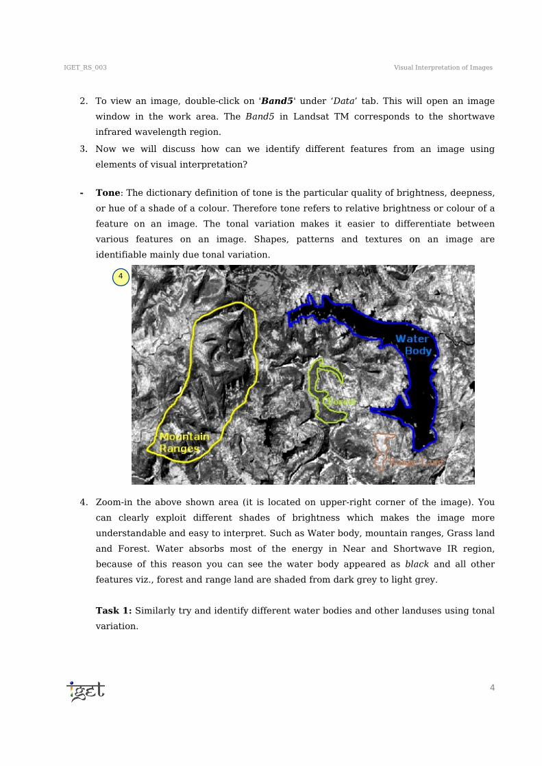
- Tone: The dictionary definition of tone is the particular quality of brightness, deepness,
or hue of a shade of a colour. Therefore tone refers to relative brightness or colour of a
feature on an image. The tonal variation makes it easier to differentiate between
various features on an image. Shapes, patterns and textures on an image are
identifiable mainly due tonal variation.
4. Zoom-in the above shown area (it is located on upper-right corner of the image). You
can clearly exploit different shades of brightness which makes the image more
understandable and easy to interpret. Such as Water body, mountain ranges, Grass land
and Forest. Water absorbs most of the energy in Near and Shortwave IR region,
because of this reason you can see the water body appeared as black and all other
features viz., forest and range land are shaded from dark grey to light grey.
Task 1: Similarly try and identify different water bodies and other landuses using tonal
variation.
4

IGET_RS_003 Visual Interpretation of Images
5
- Shape: Shape refers to external form, outline or structure of a particular feature. In
case of stereoscopic images height also determines its shape. The man made features
generally have regular, symmetric or sharp in shape while all natural features like
forest patches are irregular in shape. Most of the features can solely be identified using
the shape element of visual interpretation.
5. Go back to the image in SAGA and zoom-in to the below shown area, it is located in
centre of the image.
6. The shapes of these two features, Race course and Magarpatta city are so prominent
that we can identify these features just from its shape and with the knowledge about
the study area.
For example, if you are not familiar with study area, then you might come to a
conclusion, that the race course might be a foot ball ground or some stadium and the
Magarpatta city as a township with huge buildings.
- Size: Comparing size of a feature in context with others in an image helps in better
understanding and interpretation of an image. A quick approximation of size of a
feature makes image interpretation process faster and convenient.
7. For a better understanding, zoom-in to just above the centre of an image using zoom in
tool in menu bar. We can clearly see big white blocks kind of structures. The size of
these individual blocks is larger than the residential blocks (for example building blocks
in Magapatta city). There might be a possibility that, these building blocks whether
5

IGET_RS_003 Visual Interpretation of Images
6
belongs to industries or warehouses. In our case the large building blocks are belongs
to the TATA Motors Company. Therefore size of the feature often helps us in image
interpretation.
- Pattern: Pattern refers to spatial arrangement of features. A repeated sequence of
certain form or relationships is characteristic of many natural and constructed features
which give an added advantage to the interpreter.
8. Zoom-in to the centre area of the image as shown below. We can clearly see repetitive
patches of agricultural fields, with typically an orderly repetition of same tone and
textures generally in rectangular form with different sizes. The pattern and shape of the
agriculture fields enable us to discriminate it among forests, scrub and grass land.
Often you can see some road patterns, which divides the urban area in to regularly
spaced built-up areas is a good example of pattern.
8 8
7

IGET_RS_003 Visual Interpretation of Images
7
- Texture: Texture refers to frequency of tonal changes in a certain area of an image. It
is product of shape, size, tone, shadow and pattern of a particular feature. It decides
upon the visual roughness or smoothness of an image. Abrupt changes in grey scale
results in Rough texture while very minor tonal variations are seen in smooth textures.
Texture is scale dependent, it gradually decrease with decrease in scale. Since our
image has 30m resolution, the variation of texture is suppressed and is not readily
observable.
9. In the following google earth image, you can notice the forest canopy has rough texture
while the range land has smooth texture.
- Shadow: Shadow refers to a dark area produced by the features coming between light
rays and surface. Shadows in remote sensing images have both advantages as well as
disadvantages at the same time. The advantage is it provides certain relative height
information of the feature and also an idea of the terrain profile which is an aid to
interpretation while the features under shadows are not very well identifiable is a
disadvantage. So due consideration must be given to shadow while interpreting an
image. Particularly in microwave remote sensing shadows can be very well used in
identifying topographic variation in landforms.
10. As we go onto the image in SAGA. Mountain ranges are very clearly identifiable due to
shadow. Therefore the topography of an area can also be approximated by looking at
the shadows.
9

IGET_RS_003 Visual Interpretation of Images
8
- Association: Association is occurrence of certain feature in relation with other. Certain
features are not directly identifiable by its appearance in an image but could be
interpreted easily according to its relationship with the surroundings. For example
association of boats with water, Aircraft with runway, playground with school etc.
Visual Interpretation using colour composite:
As seen in the previous section, image can be very well interpreted and analyzed using
different structural or tonal variations in it. But very precisely identification of some features is
difficult with help of one grey colour band. In such cases use of different colour composite
images provides an aid for better and much faster interpretation. Colour composite images are
displayed using different band combinations on three primary colours (Red, Green, and Blue),
associating each spectral band of an image (not necessarily a visible band) to a separate
primary colour.
In this section we will concentrate on generally used colour compositions in Landsat image
interpretation. Firstly we will go through band details of Landsat TM satellite and further we
will move on to band compositions.
10
IGET_RS_003 Visual Interpretation of Images
9
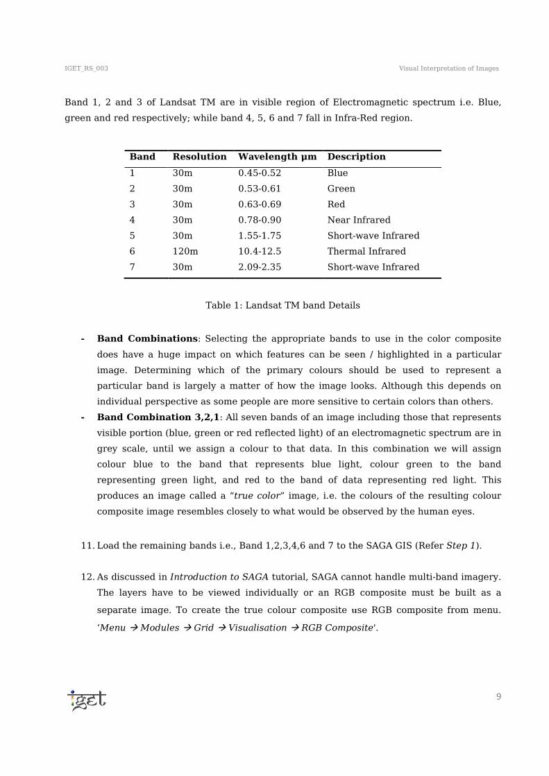
Band 1, 2 and 3 of Landsat TM are in visible region of Electromagnetic spectrum i.e. Blue,
green and red respectively; while band 4, 5, 6 and 7 fall in Infra-Red region.
Table 1: Landsat TM band Details
- Band Combinations: Selecting the appropriate bands to use in the color composite
does have a huge impact on which features can be seen / highlighted in a particular
image. Determining which of the primary colours should be used to represent a
particular band is largely a matter of how the image looks. Although this depends on
individual perspective as some people are more sensitive to certain colors than others.
- Band Combination 3,2,1: All seven bands of an image including those that represents
visible portion (blue, green or red reflected light) of an electromagnetic spectrum are in
grey scale, until we assign a colour to that data. In this combination we will assign
colour blue to the band that represents blue light, colour green to the band
representing green light, and red to the band of data representing red light. This
produces an image called a “true color” image, i.e. the colours of the resulting colour
composite image resembles closely to what would be observed by the human eyes.
11. Load the remaining bands i.e., Band 1,2,3,4,6 and 7 to the SAGA GIS (Refer Step 1).
12. As discussed in Introduction to SAGA tutorial, SAGA cannot handle multi-band imagery.
The layers have to be viewed individually or an RGB composite must be built as a
separate image. To create the true colour composite use RGB composite from menu.
‘Menu � Modules � Grid � Visualisation � RGB Composite'.
Band Resolution Wavelength μm Description
1 30m 0.45-0.52 Blue
2 30m 0.53-0.61 Green
3 30m 0.63-0.69 Red
4 30m 0.78-0.90 Near Infrared
5 30m 1.55-1.75 Short-wave Infrared
6 120m 10.4-12.5 Thermal Infrared
7 30m 2.09-2.35 Short-wave Infrared

IGET_RS_003 Visual Interpretation of Images
10
13. Select band 3, 2 and 1 for Red, Green and Blue respectively. Select ‘create’ in
composite to create a new composite and click ‘Okay’.
14. Once the composite is created, double click on ‘Composite’ to load it new map. Change
the ‘Type’ of the colour of the composite from Graduated colours to ‘RGB’ and click on
‘Apply’.
15. The land use/cover in the composite image resembles similar colour as seen by human
eyes. The true colour composite will be like below. You can notice the vegetation is in
green colour.
13
14

IGET_RS_003 Visual Interpretation of Images
11
16. Select the composite under ‘Data’ tab, goto the Object properties window and click on
the ‘Settings’ tab, now change the name from ‘Composite’ to ‘321Composite’ and
press ‘Tab’ from the key board now click on ‘Apply’.
Task 2: Describe the colours of various land use classes in the true colour image? What land
use classes are readily observable in the true colour composite?
- Band Combination 4,3,2: One of the main advantage of remote sensing is, its
capability to sense and measure the radiation beyond the visible range. We can use the
images sensed beyond the visible range to create the ‘False colour composites’. These
15
16

IGET_RS_003 Visual Interpretation of Images
12
false colour composites uncovers hidden information to our eyes. Most typical false
colour composite is 4,3,2 and is known as NIR false composite. In this composition band
4 (Near IR) is assigned on the colour red, band 3(Red) is assigned on green colour and
band 2 (Green) is assigned on blue colour. This combination is similar to 3,2,1; however
presence of Infra-Red band makes land and water boundaries more clearer and also
different types of vegetation are more apparent due to very strong reflection of
vegetation in infra-red band. See the Spectral reflectance curve for details.
17. Create RGB composite with band combination 4,3,2 and name it to ‘432Composite’ (Refer Step-13 & 16)
Task 3: Try to correlate the 432 composite with 321 composite and write a short note on the
pros & cons of each composite?

IGET_RS_003 Visual Interpretation of Images
13
- Band Combination 4,5,3: This band combination excludes first two shorter
wavelength bands thus making the image much crisper than previous two images.
Variation in moisture content is also noticeable in this band combination thus making
differentiation of various vegetation types much easier. This combination very clearly
defines the various classes in an image so probably the most commonly used band
combination for Landsat images.
18. Create RGB composite with band combination 5,4,3. The composite is as shown below:
Task 4: Create a colour composite of 742 and descried the various Land use classes in it and
explain how it is useful than other composites?
19. Now save the project via the Menu (File → Project → Save Project As), In the ‘Save AS’
popup window browse to the desired folder to save, and enter the desired name
i.e.,‘IGET_RS_003’ and click on ‘Save’. In the popup window check the Checkbox
‘Save all’ and click ‘Okay’.
Similarly various false colour compositions can be created and used depending on one’s
personal colour visualisation capabilities to make analysis and interpretation of an image
easier and faster. In this tutorial we learned brief techniques of visual interpretation of a
satellite image.