
Vision Locating Method based RGB-D Camera for Amphibious … · Vision Locating Method based RGB-D...
6
Vision Locating Method based RGB-D Camera for Amphibious Spherical Robots Abstract – Location system is crucial to many intelligent robots, especially for underwater robots. To increase the autonomous ability of amphibious spherical robots in underwater environment, an underwater vision locating system was designed in this paper, and the ToF (time of fly) camera (RGB-D camera) was used and introduced in this system. Through the image capture from the camera in water, two kinds of image information could be acquired, which are include color image and depth image. The theoretical analysis show that the location of objective could be calculate easily from those image information. In underwater environment, the depth information attenuated, a calibration experiment for distance correction was designed. These results were used for the coordinate establishing. The construction of the experimental environment and final results were provided. Through the analysis of experimental results, the feasibility of the vision locating method based the RGB-D camera was verified and this system will be used for providing the location of amphibious spherical robots in the future work. Index Terms – Vision locating method; Amphibious Spherical Robot; RGB-D camera; Depth sense; pinhole camera model I. INTRODUCTION As marine development activities become more frequent and deeper, the demand for marine detection technology and equipment is increasing. In the underwater environment beyond the diving limit, underwater robots that equipped with sensors and instruments become one of the main tools for human beings to extend their perception [1]-[2]. Underwater robots as a high-tech means in the field of marine development and utilization of the importance are no less than the role of the universe rocket in the exploration of space. And for the exploration of seabed mineral resources and the discovery of new species, those means have great potential and development space. Underwater robots work in complex and unknown marine underwater environments, good environmental perception is an important basis and key factor to improve their safety and intelligence level. Due to the limited means of sensing used in underwater environment, robot vision is more popular with underwater robot research workers, as it can get the most effective information of sensing. In recent years, robot vision technology has been developed, is widely used in industrial, medical, image processing and other fields, and in the field of positioning tracking is the best and most prominent, and then applied to the underwater environment, Its development prospects are immeasurable. At present, underwater target detection and identification, target tracking and positioning, underwater robot hand-eye cooperation and other fields have a lot of research achievement. With the development of robot intelligence, the future amphibious spherical robot will be put into the open sea area for actual survey, an effective and feasible robot positioning system, is the basic guarantee to complete the task, whether it is the process, the survey process and the robot Recovery process. Robot positioning system refers to the robot through the sensor system can be real-time access to its location in the environment and course information, is its ability to autonomously move and complete the complex tasks, to achieve real-time accurate positioning is the key to improve the autonomy of the robot's performance. With the continuous development of sensor equipment, underwater robot positioning technology is constantly moving forward, the current underwater positioning methods are the following: based on the underwater acoustic positioning method, based on the GPS positioning method and based on the visual positioning method. (1) The underwater acoustic positioning system is consisted of an underwater acoustic emission receiver and a transponder, which can be divided into long baseline, short baseline and ultra-short baseline according to the baseline length. In general, compared with the underwater robot, the underwater acoustic positioning system has the problems, that system layout, maintenance and calibration are difficult, cost time consumption and poor flexibility, and for small underwater robots, the underwater acoustic positioning system is larger, cannot be used for the underwater small robot navigation and high precision underwater absolute positioning requirements. (2) Underwater GPS positioning system is mainly composed of GPS satellite constellation, GPS positioning buoy, underwater robot signal transceiver, land-based data processing and monitoring center, radio communication, underwater acoustic communication. GPS buoy positioning has high accuracy, but due to the buoy is floating on the robot body, it cannot accurately represent the Kun Tang 1, 2 , Liwei Shi 1, 2 , Shuxiang Guo 1, 2, 3* , Shaowu Pan 1, 2 , Huiming Xing 1, 2 , Shuxiang Su 1, 2 , Ping Guo 1 , Zhan Chen 1, 2 , Yanlin He 1, 2 1 Key Laboratory of Convergence Medical Engineering System and Healthcare Technology, the Ministry of Industry and Information Technology, School of Life Science, Beijing Institute of Technology, No.5, Zhongguancun South Street, Haidian District, Beijing 100081, China 2 Key Laboratory of Biomimetic Robots and Systems, Ministry of Education, Beijing Institute of Technology , No.5,Zhongguancun South Street, Haidian District, Beijing 100081, China 3 Faculty of Engineering, Kagawa University, 2217-20 Hayashi-cho, Takamatsu, Kagawa, Japan [email protected], [email protected], [email protected] * Corresponding author
Transcript of Vision Locating Method based RGB-D Camera for Amphibious … · Vision Locating Method based RGB-D...
Vision Locating Method based RGB-D Camera for Amphibious Spherical Robots
Abstract – Location system is crucial to many intelligent robots, especially for underwater robots. To increase the autonomous ability of amphibious spherical robots in underwater environment, an underwater vision locating system was designed in this paper, and the ToF (time of fly) camera (RGB-D camera) was used and introduced in this system. Through the image capture from the camera in water, two kinds of image information could be acquired, which are include color image and depth image. The theoretical analysis show that the location of objective could be calculate easily from those image information. In underwater environment, the depth information attenuated, a calibration experiment for distance correction was designed. These results were used for the coordinate establishing. The construction of the experimental environment and final results were provided. Through the analysis of experimental results, the feasibility of the vision locating method based the RGB-D camera was verified and this system will be used for providing the location of amphibious spherical robots in the future work.
Index Terms – Vision locating method; Amphibious Spherical Robot; RGB-D camera; Depth sense; pinhole camera model
I. INTRODUCTION
As marine development activities become more frequent and deeper, the demand for marine detection technology and equipment is increasing. In the underwater environment beyond the diving limit, underwater robots that equipped with sensors and instruments become one of the main tools for human beings to extend their perception [1]-[2]. Underwater robots as a high-tech means in the field of marine development and utilization of the importance are no less than the role of the universe rocket in the exploration of space. And for the exploration of seabed mineral resources and the discovery of new species, those means have great potential and development space.
Underwater robots work in complex and unknown marine underwater environments, good environmental perception is an important basis and key factor to improve their safety and intelligence level. Due to the limited means of sensing used in underwater environment, robot vision is more popular with underwater robot research workers, as it can get the most effective information of sensing. In recent years, robot vision
technology has been developed, is widely used in industrial, medical, image processing and other fields, and in the field of positioning tracking is the best and most prominent, and then applied to the underwater environment, Its development prospects are immeasurable. At present, underwater target detection and identification, target tracking and positioning, underwater robot hand-eye cooperation and other fields have a lot of research achievement. With the development of robot intelligence, the future amphibious spherical robot will be put into the open sea area for actual survey, an effective and feasible robot positioning system, is the basic guarantee to complete the task, whether it is the process, the survey process and the robot Recovery process.
Robot positioning system refers to the robot through the sensor system can be real-time access to its location in the environment and course information, is its ability to autonomously move and complete the complex tasks, to achieve real-time accurate positioning is the key to improve the autonomy of the robot's performance.
With the continuous development of sensor equipment, underwater robot positioning technology is constantly moving forward, the current underwater positioning methods are the following: based on the underwater acoustic positioning method, based on the GPS positioning method and based on the visual positioning method. (1) The underwater acoustic positioning system is consisted of an underwater acoustic emission receiver and a transponder, which can be divided into long baseline, short baseline and ultra-short baseline according to the baseline length. In general, compared with the underwater robot, the underwater acoustic positioning system has the problems, that system layout, maintenance and calibration are difficult, cost time consumption and poor flexibility, and for small underwater robots, the underwater acoustic positioning system is larger, cannot be used for the underwater small robot navigation and high precision underwater absolute positioning requirements. (2) Underwater GPS positioning system is mainly composed of GPS satellite constellation, GPS positioning buoy, underwater robot signal transceiver, land-based data processing and monitoring center, radio communication, underwater acoustic communication. GPS buoy positioning has high accuracy, but due to the buoy is floating on the robot body, it cannot accurately represent the
Kun Tang1, 2, Liwei Shi1, 2, Shuxiang Guo1, 2, 3*, Shaowu Pan1, 2, Huiming Xing1, 2, Shuxiang Su1, 2, Ping Guo1, Zhan Chen1, 2, Yanlin He1, 2
1 Key Laboratory of Convergence Medical Engineering System and Healthcare Technology, the Ministry of Industry and Information Technology, School of Life Science, Beijing Institute of Technology,
No.5, Zhongguancun South Street, Haidian District, Beijing 100081, China
2Key Laboratory of Biomimetic Robots and Systems, Ministry of Education, Beijing Institute of Technology , No.5,Zhongguancun South Street, Haidian District, Beijing 100081, China
3Faculty of Engineering, Kagawa University, 2217-20 Hayashi-cho, Takamatsu, Kagawa, Japan [email protected], [email protected], [email protected]
* Corresponding author
current movement position and attitude of the underwater robot. (3) As the visual image contains the rich information of the target, such as color, texture, shape, with the help of computer vision theory, visual system can be through image analysis, target recognition and other means to understand the environmental information, and then estimate their own position. According to the number of video sensing devices used in the positioning process, visual positioning technology can be divided into three categories: based on monocular vision positioning technology, based on binocular vision positioning technology and multi-sensor fusion based positioning technology. Compared with other underwater positioning methods, the visual sensor is relatively small, and the system platform is built simply, and low prices, able to adapt to small robot platform. With the development of visual sensors, the RGB-D cameras have been able to obtain the depth of the image through the image information. How to convert the information obtained by the sensor into the robot's position information, in order to achieve the positioning of the robot, is a certain role in promoting for the robot intelligent development.
The structure of this paper is organized as follows. Section II introduces amphibious spherical robots and waterproof structure of ToF camera. Details of vision locating method will be elaborated in Section III. The experimental method, to correct the measuring distance from the camera and calculate the relative position from the results, and experimental results will be carried out in Section IV. And Section V will be conclusion and follow-up relevant research work.
II. STRUCTURE OF ROBOT AND TOF CAMERA
The amphibious spherical robot was developed in previous research [3]. The overall creative thinking mainly comes from the consideration of the following: Considering the wide range of work load and high strength, the robot adopts the traditional motor drive; Considering the internal space of the rich and flexible movement, the robot is the ball shape as the main body; Considering the high-speed cruise, streamlined fuselage structure may be the best choice [4]. This paper is mainly based on the amphibious spherical robots.
A. The amphibious spherical robot In the recent research, we improved its structure to make
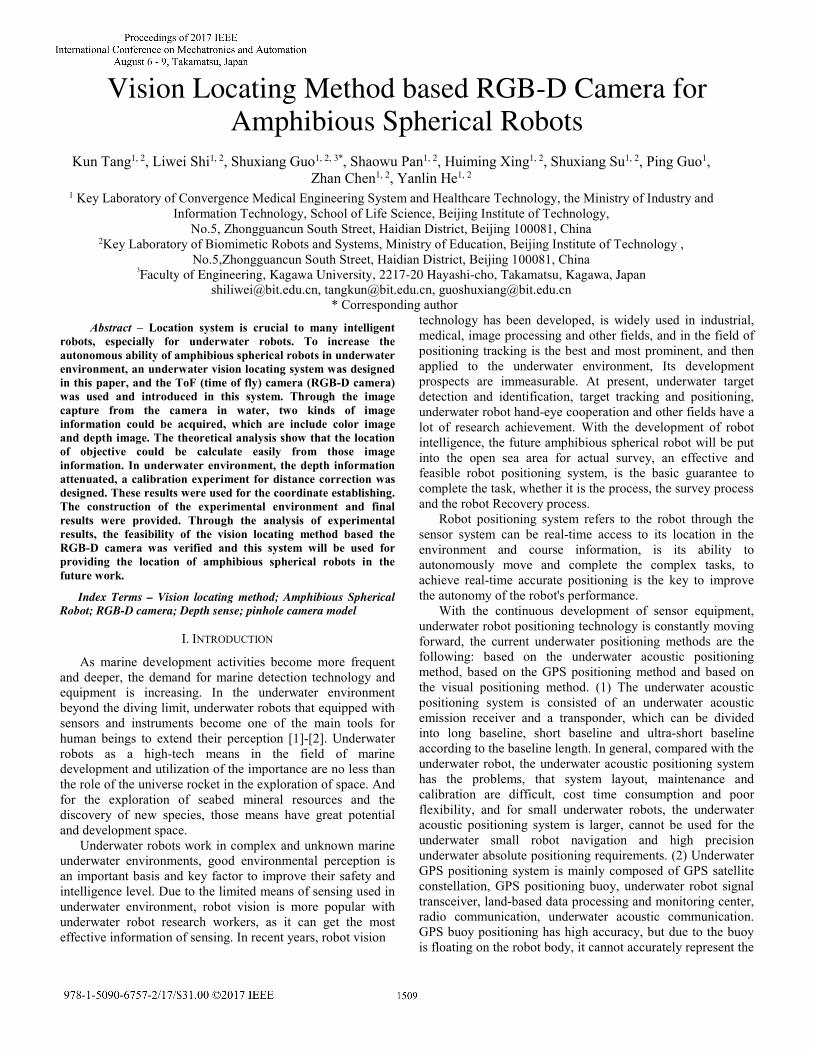
sure it is suitable for underwater environment. The diameter of robots is 350mm, and it have double waterproof structure. Bigger and stronger body of this robots provided more space and load capacity to install more sensor on robot, and then it improved environmental perception for amphibious spherical robots. As show in Fig. 1, we have installed the GPS sensor, gyroscopes and inertial sensor, underwater communicating sonar, depth gauge and camera on the robots reasonably.
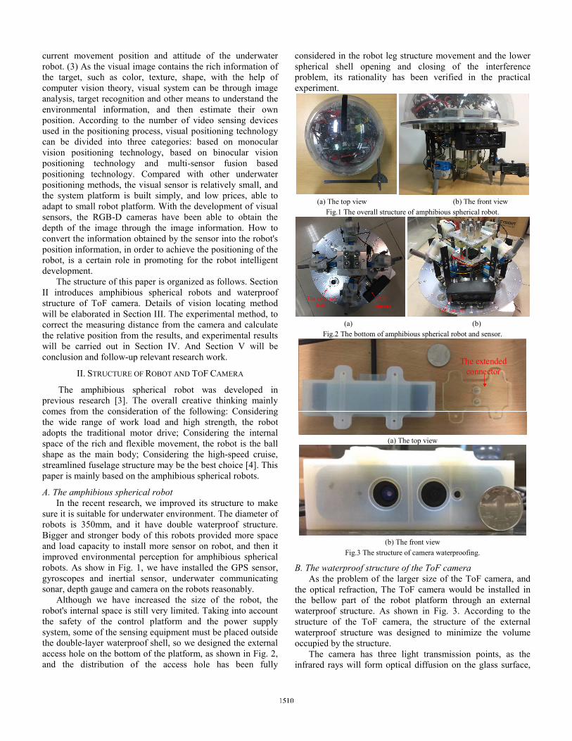
Although we have increased the size of the robot, the robot's internal space is still very limited. Taking into account the safety of the control platform and the power supply system, some of the sensing equipment must be placed outside the double-layer waterproof shell, so we designed the external access hole on the bottom of the platform, as shown in Fig. 2, and the distribution of the access hole has been fully
considered in the robot leg structure movement and the lower spherical shell opening and closing of the interference problem, its rationality has been verified in the practical experiment.
(a) The top view (b) The front view
Fig.1 The overall structure of amphibious spherical robot.
a
The external hole
ToF camera
ToF camera
Sonar
(a) (b)
Fig.2 The bottom of amphibious spherical robot and sensor.
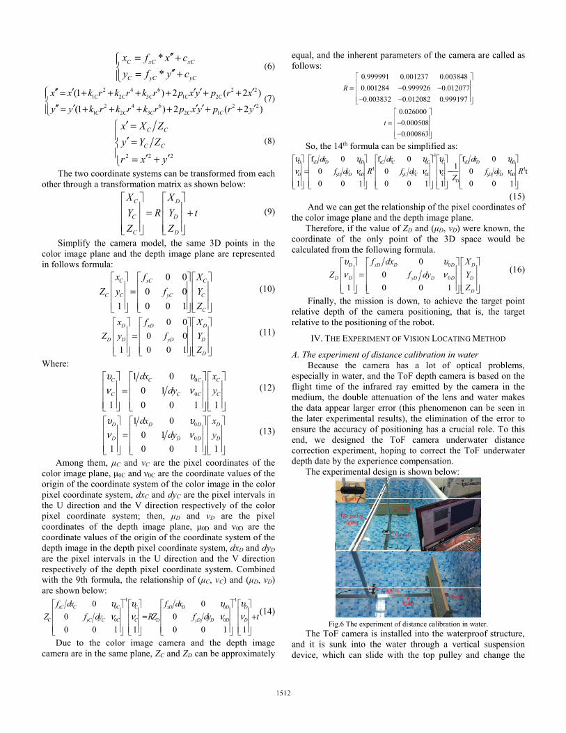
The extended connector
(a) The top view
(b) The front view
Fig.3 The structure of camera waterproofing.
B. The waterproof structure of the ToF camera As the problem of the larger size of the ToF camera, and
the optical refraction, The ToF camera would be installed in the bellow part of the robot platform through an external waterproof structure. As shown in Fig. 3. According to the structure of the ToF camera, the structure of the external waterproof structure was designed to minimize the volume occupied by the structure.
The camera has three light transmission points, as the infrared rays will form optical diffusion on the glass surface,

the independent separation and waterproof of the three points is needed, and between the two adjacent light transmission point to increase the isolation structure. And then the structure was fixed on the external access hole through an extended connector, and this structure can ensure that the camera keep the robot horizontally connected.
The structure of the improved robot and the waterproof of the camera were designed to provide a good research platform for the underwater positioning of the robot.
III. VISION LOCATING METHOD BASED RBG-D CAMERA
Vision for robots, just as eyes are as important as humans. Using the ToF camera to determine the position of the target object, through the camera's color channel to identify the target object, the depth channel to match the depth of the object information, through the coordinate solution and coordinate transformation, the position of target object relative to the camera (the robot) would be calculated.
The principle diagram of vision locating method in this paper is shown in Fig. 4, which is divided into two parts: 1) The target recognition part based on the color image, this part used the method of image feature extraction and feature classification to identify the target object, and the coordinate of color image was extracted that be needed to transform the coordinate of depth image. This part is not the main content of this paper. 2) The image calibration and three-dimensional coordinate establishment based on the depth image would be introduced in this part. The target coordinates acquired from the first part would be converted into the coordinates of the depth image. Using the depth camera model, the 3D coordinate information of the target in depth coordinates is deduced, and the position of the target relative to the robot is obtained. This paper mainly introduced the depth image calibration and 3D coordinate establishment based on the ToF camera.
ToF camera
The color image
The depth image
Feature detection
Feature matching
The depth pixel coordinate of target
The color pixel coordinate of target
The depth date of target
The 3D coordinate in the robot coordinate space
The results of feature
classification
Camera Robot
PC
Fig.4 The principle diagram of vision locating method.
A. The imaging model of the ToF camera The ToF camera's imaging principle is based on the
pinhole camera model. As shown in Fig. 5. The basic parameters of camera are shown below.
fo
Y
Z
Xq
p
y
xQ
P
Y
X
Fig.5 The pinhole camera model.
Each color and depth node is modeled by the following matrices:
0
0
0 0 1
x x
y y
f c
A f c
=
, [ ]1 2 1 2 3k k p p k (1)
Here, fx ,fy are respectively the focal length in pixel-related units along the x and y axis, cx, cy are respectively the principal point of the camera along the x and y axis, k1, k2, k3 are the radial distortion coefficients, p1 and p2 are the tangential distortion coefficients. The relative position of the color and depth cameras would be describe by the foollowing matrices:
11 12 13
21 22 23
31 32 33
r r r
R r r r
r r r
=
,
1
2
3
t
t t
t
=
(2)
Among them, R is a rotation matrix and t is the translation matrix expressed in meters. These matrices are used to convert 3D coordinates from the depth coordinate system to the color coordinate system. These matrices are frame format invariant and do not depend on the contents of the scene. B. Coordinate establishment for vision locating method
According to the pinhole camera model, the pixel coordinates of the depth image and the coordinates of the depth coordinate system can click on the formula conversion:
Let (XD, YD, ZD) be the coordinates of a 3D point in the world coordinate space expressed in the depth coordinate system and (xD, yD) the coordinates of the projection point in pixels in the depth camera plane. The projection point can be computed with the following formula:
*
*D xD xD
D yD yD
x f x c
y f y c
′′= + ′′= +
(3)
2 4 6 2 21 2 3 1 2
2 4 6 2 21 2 3 2 1
(1 ) 2 ( 2 )
(1 ) 2 ( 2 )
D D D D D
D D D D D
x xx k r k r k r p x y p r x
y y k r k r k r p x y p r y
′′ ′ ′ ′ ′ = + + + + + +
′′ ′ ′ ′ ′= + + + + + + (4)
2 2 2
D D
D D
x X Z
y Y Z
r x y
′ = ′ = ′ ′= +
(5)
Similarly, let (XC, YC, ZC) be the coordinates of a 3D point in the world coordinate space expressed in the color coordinate system and (xC, yC) the coordinates of the projection point in pixels in the color camera plane. The projection point can be computed with the following formula:
*
*C xC xC
C yC yC
x f x c
y f y c
′′= + ′′= +
(6)
2 4 6 2 21 2 3 1 2
2 4 6 2 21 2 3 2 1
(1 ) 2 ( 2 )
(1 ) 2 ( 2 )
C C C C C
C C C C C
x x k r k r k r p x y p r x
y y k r k r k r p x y p r y
′′ ′ ′ ′ ′ = + + + + + +
′′ ′ ′ ′ ′= + + + + + +(7)
2 2 2
C C
C C
x X Z
y Y Z
r x y
′ = ′ = ′ ′= +
(8)
The two coordinate systems can be transformed from each other through a transformation matrix as shown below:
C D
C D
C D
X X
Y R Y t
Z Z
= +
(9)
Simplify the camera model, the same 3D points in the color image plane and the depth image plane are represented in follows formula:
0 0
0 0
1 0 0 1
C xC C
C C yC C
C
x f X
Z y f Y
Z
=
(10)
0 0
0 0
1 0 0 1
D xD D
D D yD D
D
x f X
Z y f Y
Z
=
(11)
Where:
0
0
1 0
0 1
1 0 0 1 1
C C C C
C C C C
dx x
dy y
υ υν ν =
(12)
0
0
1 0
0 1
1 0 0 1 1
D D D D
D D D D
dx x
dy y
υ υν ν =
(13)
Among them, μC and νC are the pixel coordinates of the color image plane, μ0C and ν0C are the coordinate values of the origin of the coordinate system of the color image in the color pixel coordinate system, dxC and dyC are the pixel intervals in the U direction and the V direction respectively of the color pixel coordinate system; then, μD and νD are the pixel coordinates of the depth image plane, μ0D and ν0D are the coordinate values of the origin of the coordinate system of the depth image in the depth pixel coordinate system, dxD and dyD are the pixel intervals in the U direction and the V direction respectively of the depth pixel coordinate system. Combined with the 9th formula, the relationship of (μC, νC) and (μD, νD) are shown below:
1 1
0 0
0 0
0 0
0 0
0 0 1 1 0 0 1 1
xC C C C xD D D D
C yC C C C D yD D D D
f dx f dx
Z f dy RZ f dy t
υ υ υ υν ν ν ν
− − = +
(14)
Due to the color image camera and the depth image camera are in the same plane, ZC and ZD can be approximately
equal, and the inherent parameters of the camera are called as follows:
0.999991 0.001237 0.003848
0.001284 0.999926 0.012077
0.003832 0.012082 0.999197
R
= − − − −
0.026000
0.000508
0.000863
t
= − −
So, the 14th formula can be simplified as: 1
0 0 01 1
y 0 y 0 y 0
f 0 f 0 f 01
0 0 0 t
1 0 0 1 0 0 1 1 0 0 1
D xD D D xC C C C xD D D
D D D D C C C C D D DD
dx dx dx
f dy R f dy f dy RZ
υ υ υ υ υν ν ν ν ν
−
− −
= −
(15) And we can get the relationship of the pixel coordinates of the color image plane and the depth image plane.
Therefore, if the value of ZD and (μD, νD) were known, the coordinate of the only point of the 3D space would be calculated from the following formula.
0
0
0
0
1 0 0 1
D xD D D D
D D yD D D D
D
f dx X
Z f dy Y
Z
υ υν ν =
(16)
Finally, the mission is down, to achieve the target point relative depth of the camera positioning, that is, the target relative to the positioning of the robot.
IV. THE EXPERIMENT OF VISION LOCATING METHOD
A. The experiment of distance calibration in water Because the camera has a lot of optical problems,
especially in water, and the ToF depth camera is based on the flight time of the infrared ray emitted by the camera in the medium, the double attenuation of the lens and water makes the data appear larger error (this phenomenon can be seen in the later experimental results), the elimination of the error to ensure the accuracy of positioning has a crucial role. To this end, we designed the ToF camera underwater distance correction experiment, hoping to correct the ToF underwater depth date by the experience compensation.
The experimental design is shown below:
Camera
Camera
Object
Object
Camera
Ruler
The pulley runner
Fig.6 The experiment of distance calibration in water.
The ToF camera is installed into the waterproof structure, and it is sunk into the water through a vertical suspension device, which can slide with the top pulley and change the

distance between the camera and the object. The distance measuring tools are equipped on the top pulley runner and the bottom of the pool parallel to the runner, and are used for measure the actual distance of the camera from the target object. In this experiment, the target is a plate with a larger area, the plate is parallel to the plane of the camera, and placed vertically at the bottom of the pool. The experimental environment is an indoor pool, which the size is 2.81m*2.01m*1.00m, and the depth of water is 0.7m.
In the experiment, the camera start from the minimum imaging distance (ie, the minimum effective depth data), keeping the target object out, we move the suspension device, drive the camera to move, and record the imaging result and depth data at regular intervals. The experimental record process is shown as follows:
Fig.7 The experimental record process of distance calibration in water.
B. The experiment of vision locating method in water From the last experiment, we have learned that the
distance measurement of the ToF camera is effective at close range. And then, we would design the underwater visual positioning experiment on amphibious spherical robots to verify the feasibility and effectiveness of the underwater visual locating method based on the ToF camera.
The experiment building process is as follows: two amphibious spherical robot sinking into the water, a fixed one as a positioning robot, the other one as the object of observation. The positioning robot recognizes the robot that appears within the field of view. When it is determined that the object is the robot, it determines whether the depth information is valid. If the depth value is valid, it calculates the position coordinates of the robot under the position of the positioning robot. The actual coordinates are obtained by the measurement, and the coordinates of the two groups are compared. The experimental environment is also an indoor pool. The experimental process is shown in Fig. 8.
The robot as object
Positioning robotReference
coordinates
Fig.8 The experimental process of vision locating in water.
C. Experimental results In the experiment of distance calibration, firstly, the
sampling interval is 10cm, 10 sets of dates are recorded every time. The result is shown below:
Fig.9 The experimental result of distance calibration in water.
From the Fig. 9, we can find that, with the relative distance between the camera and the measured object increases from zero, the depth date appeared about 10cm, and the depth date gradually decay after 40cm. the result is the effective range of TOF camera in the water is the range of 10cm-40cm.
And in the effective range, the sampling interval become 1cm, 11 sets of dates are recorded every time. The result is shown below:
Fig.10 The experimental result of distance calibration in water.
It can be seen from the experimental results, the range effect of ToF camera is attenuated in water, but it still maintains a certain degree of measurement linearity, composite experience compensation error correction data model. The empirical formula is follow:
real 0.778* 7.289messureD D= + (17)
Fig.11 The 3D result of vision locating in water.

The 3D result of vision locating in water is shown in the Fig. 11. We conducted a total of 50 experiments, and chosen 30 effective points for positioning effect analysis. As the value of the reference coordinate’s y axis is 0, the coincidence effect between the reference point and the real positioning point is not obvious in 3D coordinates. We change the view of the positioning points, the results is shown below:
Fig.12 The projection result in OXZ plan.
From the Fig. 12 we can find that the positioning points and the reference points can be kept substantially coincident. The results of each direction with the reference point for comparison statistics, the results shown in Table 1. In the x-axis direction, the absolute value of the coordinates calculated by the vision locating method is less than reference points. The maximum deviation of the non-calibration and calibration is 57.720mm and 63.852mm respectively. In the y-axis direction, the maximum deviation is 31.654mm and 30.395mm. In the z-axis direction, the value is determined by the validity of the depth information of the ToF camera, and it can be seen from the results that the maximum deviation is 37.151mm and the standard deviation is 2.438.
TABLE I
UNDERWATER VISION LOCATING ERROR TABLE.
x-axis direction y-axis direction z-axis
direction Non-
calibration
Calibration
Non-calibrat
ion
Calibration
Calibration
Mean(mm) 19.568 27.569 9.530 9.292 30.272
Maximum absolute
deviation(mm)
57.720 63.852 31.654 30.395 37.151
Standard deviation
14.586 15.353 9.030 8.883 2.438
All above the experiments demonstrated that visual
locating method based on the ToF camera can be used for the underwater positioning of the amphibious spherical robot effectively. The method after camera parameter correction has better robustness. However, the reference points exists measurement error, it can’t be used to evaluate the positioning accuracy.
V. CONCLUSIONS
The main research of this paper is vision locating method based RGB-D camera for amphibious spherical robot in water. In this locating system, the color image was used for object recognition, and the depth image was used for calculating the 3D coordinate of robots. Through the analysis of the camera model, the relative position between the robots can be confirm with the image coordinate and distance ZD. From the experimental results, we find the vision locating method based on RGB-D camera is effective. In future, we will design an outdoor experiment to verify the effectiveness and feasibility of the method, and this system would be used to help the robot’s navigation and motion control strategy.
ACKNOWLEDGEMENTS
This work was supported by National Natural Science Foundation of China (61503028, 61375094), and Excellent Young Scholars Research Fund of Beijing Institute of Technology (2014YG1611). This research project was also partly supported by National High Tech. Research and Development Program of China (No.2015AA043202).
REFERENCES [1] Kim, Doosik, et al. “Plasma molding over surface topography: Simulation
and measurement of ion fluxes, energies and angular distributions over trenches in RF high density plasmas.” Journal of IEEE Transactions on Plasma Science, vol. 31, no. 4, pp. 691-702, August 2009.
[2] Y. Li, and K. Yan. “Application of autonomous underwater vehicle in lake test of deep-sea mining system.” Journal of Ocean Engineering, vol. 24, no. 2, pp. 61-66, 2006.
[3] S. Guo, J. Du, X. Ye, R. Yan, H. Gao, “The computational design of a water jet Propulsion spherical underwater vehicle”, Proceedings of the 2011 IEEE International Conference on Mechatronics and Automation, pp. 2375-2379, 2011.
[4] S. Pan, S. Guo, L. Shi, Y. He, Z. Wang and Q. Huang, “A Spherical Robot based on all Programmable SoC and 3-D Printing”, Proceedings of 2014 IEEE International Conference on Mechat, pp. 150-155, 2014.
[5] L. Shi, S. Guo, S. Mao, et al. “Development of an Amphibious Turtle-Inspired Spherical Mother Robot”, Journal of Bionic Engineering, vol. 10, no. 4, pp. 446-455, 2013.
[6] Y. He, L. Shi, S. Guo, et al. “Preliminary mechanical analysis of an improved amphibious spherical father robot”, Journal of Microsystem Technologies, vol. 22, no. 8, pp. 2051-2066, 2016.
[7] L. Shi, S. Pan, S. Guo, et al. “Design and evaluation of quadruped gaits for amphibious spherical robots”, Proceedings of IEEE International Conference on Robotics and Biomimetics, pp. 13-18, 2017.
[8] S. Pan, L. Shi, S. Guo, et al. “A low-power SoC-based moving target detection system for amphibious spherical robots”, Proceedings of IEEE International Conference on Mechatronics and Automation, pp. 1116-1121, 2015.
[9] L. Shi, R. Xiao, S. Guo, et al. “An attitude estimation system for amphibious spherical robots”, Proceedings of IEEE International Conference on Mechatronics and Automation, pp. 2076-2081, 2015.
[10] R. Lins, S. Givigi, P. Kurka. “ Vision-Based Measurement for Localization of Objects in 3-D for Robotic Applications”, Journal of IEEE Transactions on Instrumentation & Measurement, vol. 64, no. 11, pp. 2950-2958, 2015.
[11] X. Fang, W. Yan, F. Zhang, et al. “Formation geometry of underwater positioning based on multiple USV/AUV”, Journal of Systems Engineering & Electronics, vol. 36, no. 5, pp. 947-951, 2014.
[12] S. Guo, Y. He, L. Shi, et al. “Modal and fatigue analysis of critical components of an amphibious spherical robot”, Journal of Microsystem Technologies, vol. 23, no. 6, pp. 2233-2247, 2017.