Video Task Force H.323 VIDEO FOR ITN - Duke University
64
H.323 VIDEO FOR ITN An Implementation Strategy Recommendations to the Indiana Telecommunications Network Prepared By IP Video Task Force Indiana Higher Education Telecommunication System December 3, 2001 Internet Protocol Video Task Force I PVTF
Transcript of Video Task Force H.323 VIDEO FOR ITN - Duke University

H.323 VIDEO FOR ITN An Implementation Strategy Recommendations to the Indiana Telecommunications Network Prepared By IP Video Task Force Indiana Higher Education Telecommunication System December 3, 2001
I n t e r n e t P r o t o c o l
V id e o T a s k F o r c eI P V T F
ii
Contents
Page Participant List .........................................................................................................iii Executive Summary .................................................................................................iv Introduction..............................................................................................................1 IP Video Endpoint (Codec) Evaluation and Recommendations .............................2 H. 323 Multipoint Control Unit (MCU) ..................................................................13 Gatekeeper Topology...............................................................................................17 Support for Gateways...............................................................................................21 IP Voice/Video Dial Plan.........................................................................................22 Directory Services....................................................................................................28 Quality of Service (QoS) .........................................................................................33 Appendix A: ITU Audio Standards .........................................................................41 Appendix B: ITU Video Standards..........................................................................42
Appendix C: Comparison of Desktop Codecs by Vendor Model ...........................43
Appendix D: Comparison of Room System Codecs by Vendor Model..................46 Appendix E: Codec Review Synopsis .....................................................................50 Glossary....................................................................................................................53

iii
Participant List IP Video Task Force Members Vern Draper, Ball State University Fred Nay, Ball State University, Co-Chair Mike Huffman, Indiana Department of
Education Alan Benjamin, Indiana Department of
Information Technology Tim Holt, Indiana Cooperative Library
Services Authority Gerry Oliver, Indiana State University Jeff Steinmiller, Indiana State University Steve Egyhazi, Indiana University Doug Pearson, Indiana University Art Mahan, Indiana Wesleyan University Brian Stone, Indianapolis Marion County
Public Library Jason Whitaker, Ivy Tech State College Jerry Sullivan, Intelenet Commission Chad Miller, Intelenet Commission Michael Gay, Purdue University Don Kindred, Purdue University Pat Smoker, Purdue University Ed Stanish, Purdue University Wayne Bohm, University of Southern
Indiana Tim Lockridge, University of Southern
Indiana Carl Koenig, Vincennes University Ron Dekoker, IHETS Dave Kaufman, IHETS Tony McClelland, IHETS Kevin Siminski, IHETS Alan Stillerman, IHETS Ed Stockey, IHETS, Co-Chair Marty Stricker, IHETS Ed Tully, IHETS
Dial-Plan Committee Members Vern Draper, Ball State University Fred Nay, Ball State University Steve Egyhazi, Indiana University Michael Gay, Purdue University Earle Nay, Purdue University Ron Dekoker, IHETS Tony McClelland, IHETS Kevin Siminski, IHETS Shawn Solomon, IHETS Alan Stillerman, IHETS, Chair Ed Stockey, IHETS
Other Contributors Kevin McMenamy, Cisco Systems Alan Glowacki, Cisco Systems Tim Cornett, 1st Virtual Communications Matt Albers, 1st Virtual Communications Leroy Leach, SBC DataComm Kathy Drybread, WireOne Document prepared by Michael Gay Shawn Solomon Alan Stillerman Ed Stockey

iv
Executive Summary In July 2001, the Indiana Higher Education Telecommunication System (IHETS) Integrated Technologies Committee (ITC) formed an IP Video Task Force (IPVTF) to evaluate two-way interactive video over IP networks using the H.323 protocol and to recommend to the Indiana Telecommunications Network (ITN) various hardware/software and policy components required for implementing H.323 IP video. This report will help network designers, technical coordinators, faculty, students, and administrators understand the basic functioning of H.323-based videoconferencing. The section dealing with codecs should provide schools, libraries, and other institutions with guidance on the purchase of equipment. Task Force recommendations will provide direction for ITN to implement a state-of-the-art H.323 videoconferencing environment that is robust and scalable for the state of Indiana. The topics reviewed and discussed by the IPVTF include:
• H.323 Codecs (endpoint terminal equipment) • Multipoint Conference Units (MCU) • Gatekeepers • Gateways • Dial Plan Development • Directory Services • Quality of Service (QoS)
The H.323 standard covers four fundamental hardware elements of a complete network system: terminals (also called codecs), gatekeepers, gateways, and MCUs. Figure 1 presents a sample implementation of these four elements, also demonstrating how the IP technology will interface with existing ISDN and ATM technology. Dial plans and directory services are policy and support mechanisms used to make an H.323 network easier to use. Finally, QoS is a function of the underlying IP network, transparent to the end-user while it is working but immediately evident if it fails. Many education institutions are already using IP-based videoconferencing. Indiana University, Purdue University, and Ball State University are delivering instruction via IP videoconferencing, while libraries and K-12 institutions are using the technology for administrative videoconferencing. It is therefore important that ITN provide a consistent service across the shared network resource soon to avoid later having to work around multiple competing investments in equipment and policy components. Because this technology is rapidly evolving and changing, the actual implementation of IP video on ITN will undoubtedly evolve along with the technology. Sections of this document should, however, continue to be useful reference tools for ITN customers and others considering investments in IP video.

v
Figure 1
Workstation
Workstation
Workstation
H.323 IP VideoTerminal(Codec)
ISDN VideoTerminal(Codec)
ATM VideoTerminal(Codec)
Gatekeeper
MultipointConference
Units
VideoGateway
Courtesy Cisco Systems, Inc.
VideoInfrastructure
At AGlance
GG
ITN
ISDN

vi
Summary Recommendations Listed below are the recommendations of the IPVTF. Please see each specific section for more detail. Videoconferencing Endpoints (Codec) Recommendation: The IP Video Task Force recommends that ITN support products from the following manufacturers. It is also recommended that ITN customers purchase from these choices in order to have access to a larger knowledge base for troubleshooting. Polycom:
Appliance Based Room Systems • Viewstation FX • Viewstation VS4000
• Viewstation MP
Appliance Based Set-Top Systems • Viewstation H.323 • Viewstation SP128
• Viewstation SP384 • Viewstation 128
PC Based Desktop System • ViaVideo
VCON:
PC Based Room Systems • Media Connect 8000 model 3, MC8000
PC Based Desktop System • ViGO • Escort
• Cruiser
Multipoint Control Unit (Bridge) Recommendation: The IPVTF recommends the ACCORD MGC-100 MCU for the following reasons:
• It supports H.323 (IP), H.321 (ATM), and H.320 (ISDN) protocols. • Participants in the tests rated Accord highest for audio and video quality. • Implementation of the Accord will allow for unified scheduling across IP and ATM
video. Other bridges require third-party software to achieve this. • The Accord MCU was designed for carrier or service providers. • The Accord provides for more continuous-presence options. • Continuous presence on the Accord is symmetric. For example, four 384 kbps calls input
are output as one 384 kbps call. On other MCUs, four 384 kbps calls input are output as one 1.344 Mbps call. This would use the entire bandwidth of a T1 link and significantly increase the customer’s cost for videoconferencing.
• The Accord has more functionality features than the other MCUs, allowing for greater flexibility in the provision of services.

vii
Gatekeeper Recommendation: The IPVTF recommends that ITN adopt a hierarchical gatekeeper plan consisting of a “Main Directory” gatekeeper, “Zone” gatekeepers, and “Institutional” gatekeepers. Gateway Recommendation: The IPVTF recommends the purchase of a Radvision L2W-323 PRI gateway to support inbound ISDN-to-ITN traffic. Dial Plan Recommendations: The IPVTF recommends the following:
• The dial plan will take the form of: E[*T]ZZZNNNNNNN; where E = Exit zone; *T = Technology prefix; Z = Area code; and N = 7 digit dialing extension number.
• The dial plan will support ISDN codecs that have specific circuit restrictions through the use of Technology prefixes.
• A PRI be purchased to support “ISDN off net” to “IP on net” Point-to-Point calls. • An ISDN to IP gateway be purchased to support “ISDN off net” to “IP on net”
Point-to-Point calls. Directory Services Recommendation: The IPVTF recommends that First Virtual Communications, Inc., Click to MeetTM be used to provide directory services. Quality of Service (QoS) Recommendation: The IPVTF recommends that the ITN provide QoS throughout the network up to the point of demarcation for ITN, the LAN interface on the router. At this point, packets will continue to be “prioritized;” however, the customer to determine how to act upon those packets.

1
Introduction In July 2001, the Indiana Higher Education Telecommunication System (IHETS) Integrated Technologies Committee (ITC) formed an IP Video Task Force (IPVTF) to evaluate two-way interactive video over IP networks using the H.323 protocol and to recommend to the Indiana Telecommunications Network (ITN) various hardware/software and policy components required for implementing H.323 IP video. This report will help network designers, technical coordinators, faculty, students, and administrators understand the basic functioning of H.323-based videoconferencing. The section dealing with codecs should provide schools, libraries, and other institutions with guidance on the purchase of equipment. Task Force recommendations will provide direction for ITN to implement a state-of-the-art H.323 videoconferencing environment that is robust and scalable for the state of Indiana. The topics reviewed and discussed by the IPVTF include:
• H.323 Codecs (endpoint terminal equipment) • Multipoint Conference Units (MCU) • Gatekeepers • Gateways • Dial Plan Development • Directory Services • Quality of Service (QoS)
The H.323 standard covers four fundamental hardware elements of a complete network system: terminals (also called codecs), gatekeepers, gateways, and MCUs. Figure 1 presents a sample implementation of these four elements, demonstrating how the IP technology will interface with existing ISDN and ATM technology. Dial plans and directory services are policy and support mechanisms used to make an H.323 network easier to use. Finally, QoS is a function of the underlying IP network, transparent to the end-user while it is working but immediately evident if it fails. Many education institutions are already using IP-based videoconferencing. Indiana University, Purdue University, and Ball State University are delivering instruction via IP videoconferencing, while libraries and K-12 institutions are using the technology for administrative videoconferencing. It is therefore important that ITN provide a consistent service across the shared network resource soon to avoid later having to work around multiple competing investments in equipment and policy components. Because this technology is rapidly evolving and changing, the actual implementation of IP video on ITN will undoubtedly evolve along with the technology. Sections of this document should, however, continue to be useful reference tools for ITN customers and others considering investments in IP video.

2
IP Video Endpoint (Codec) Evaluation and Recommendations
This section reviews IP codecs according to user needs, performance, and compatibility. Accompanying tables provide summary comparisons of various vendor offerings. PRIMARY QUESTIONS The Task Force first examined endpoint equipment to better understand the end-user experience as H.323 implementation proceeds on ITN. Selection criteria thus addressed both questions pertaining to user friendliness and reliability issues as well as more technical questions affecting reliability and compatibility issues. To further refine the criteria and understand the end-user’s point of view, several H.323 terminals (codecs) were evaluated. User Concerns
• What is H.323 terminal equipment? • What is a codec? • Why not use NetMeeting®? • How many brands of equipment should ITN support and how will the decision affect the
end-user? • What is a room system versus a set-top system versus a desktop system and what are the
applications of each type? Technical Support Concerns
• What are the differences and advantages/disadvantages between appliance-based codecs and PC-based codecs?
• What are the compatibility concerns between different manufacturers and technologies? ANSWERS
User Concerns What is H.323 terminal equipment? Terminal equipment refers to any piece of equipment used to call or receive calls on a network. Specifically, H.323 terminal equipment is any piece of equipment used to make or receive calls on an IP based network. The equipment takes the form of a camera (transmits the user’s picture), monitor (displays picture and audio from the far end site), microphone (transmits end-user’s audio to far end site), codec (PC or appliance based, see below), keyboard, and mouse (provide direct interface with the video conferencing unit). This is the only equipment with which the end-user directly interacts when making or receiving a call. What is a codec? The word codec is an acronym for COder/DECoder. In short, a codec is a piece of hardware or software that takes some signal (such as video or audio) and converts it to a format suitable for transportation using a specific set of protocols. Equipment on the receiving end must also use these same protocols. The H.323 standard is a collection of protocols designed to ensure compatibility between products of various manufacturers. Even though the term
3
“codec” specifically refers to the hardware or software converter, the term has come to include the entire set of videoconferencing terminal equipment. Someone saying “codec” is most likely referring to a set of terminal equipment. The terms “videoconferencing terminal” and “codec” will be used interchangeably throughout this document. Why not use NetMeeting®? NetMeeting® and CUSeeMe are software based codecs. There is no hardware. NetMeeting® and CUSeeMe are totally dependent upon the processor’s power to encode and decode audio and video. The more programs that are open and running in the background, the less processing power there is for NetMeeting® and CUSeeMe to use. Moreover, NetMeeting® and CUSeeMe can only send a video stream at 128 kbps. While this may be acceptable for point-to-point meetings, this will not be adequate for multipoint conferences on a bridge that requires 384 kbps. Not all bridge manufactures support the use of NetMeeting® at this time. Therefore, at this time, NetMeeting® and CUSeeMe should not be supported or allowed into multipoint conferences. As technology improves, this decision will be reevaluated. How many brands of equipment should ITN support and how will the decision affect the end-user? The IPVTF determined it would be wise to support products from two manufacturers. Choosing one manufacturer would unduly restrict customer choice. Three or more product lines would be expensive to support. Choosing two allows ITN customers to select the codec that best meets their needs, while allowing ITN support staff to maintain an in-depth knowledge of the equipment. Keeping the number of manufacturers to a minimum will also assist ITN by allowing staff and subcontractors to focus on resolving any issues associated with the products. ITN customers can choose another manufacturer if they wish; however, ITN staff will not be able to support that equipment if the end-user has difficulty. What is a room system versus a set-top system versus a desktop system and what are the applications of each type? Researching manufacturers made it clear that various vendors interpret videoconferencing terminal endpoint solutions differently. To clarify discussion and evaluation, the IPVTF devised the following three classifications for terminal endpoint equipment: Room System, Set-Top System, and Desktop System.
Room System A room system is a vendor’s top of the line product designed to provide medium and large corporations, government, and educational institutions with custom room configurations. These systems are used in situations requiring high-quality video performance and extensive conferencing capabilities for applications such as distance learning, boardroom conferencing and high performance multi-site conferencing. Performance is based on providing IP data rates as fast as 2 Megabits per second. These systems typically support multiple video and audio inputs such as document cameras, computer video converters, and VCRs. Support for one to three video displays is also common. Complete systems may come with two or more 32” viewing monitors or can be used with larger projection systems. These systems can be permanently built into a room or set up as semi-mobile units that can be taken to another room if necessary. Some units even have built-in streaming services. The main advantages to these systems are video quality and built-in multipoint services. The main disadvantage is price; these systems start in price at $14,000 list and go up from there.

4
Set-Top System The term set-top system usually refers to a vendor’s mid-level product designed for small to medium sized conference rooms. This system can look just like the room system with monitors and carts, or it can be a smaller unit that sits on top of a monitor. These systems typically will perform the same as the room systems at lower data rates; however, the set-top systems typically do not support data rates above 768K and do not have the built-in multipoint conference capability. The list pricing for set-top systems can be in the $3,000 to $12,000 range. One advantage to the set-top solution is that products on the lower end of this pricing scale can give a user excellent conference room or classroom performance as long as they do not require the extra services or options offered by the room systems. The disadvantages are that multipoint services would need to be provided elsewhere (such as IHETS) and that higher data rates (more than 768 Kilobits per second) are not attainable. Desktop System A desktop system, simply put, is a videoconferencing terminal, either hardware or software, that interacts directly with the personal computer on a desk. It is designed to be a one-person unit, making it unsuitable for a conference room environment; but it can be very useful for an office or classroom/lab-station solution. It will either connect through the USB port or will have a hardware card to be installed. The speed of the computer processor will directly affect performance. Desktop systems list from $599 to $4,995. The advantage of such a unit is its low-cost focus on an individual user, with no special room or setup needed. Within minutes of installation, a user can talk face to face to someone using another desktop system or someone with a $50,000 room system. The disadvantage to this type of system is that it is not designed for conference rooms.
Technical Support Concerns What are the differences and advantages/disadvantages between appliance-based codecs and PC-based codecs? The fundamental difference between the two is that PC-based systems rely on a personal computer as a platform for the user interface, and in some cases the entire system, while appliance-based systems are self contained and do not use MS-DOS or Windows.
PC-based Videoconferencing Terminal A PC-based videoconferencing terminal is completely integrated into a PC (not necessarily a desktop system, this could be a room system). The designers of such systems started with a Windows platform and added the necessary hardware and software components from that point. The primary advantage is that these systems can give the user immediate access to PC display capabilities in order to show PowerPoint slides or other software screens. These units typically support a method of application sharing as defined by the T.120 application-sharing standard. This allows an end-user to collaborate with an endpoint by electronically sharing a document or whiteboard and sharing control of the document or whiteboard. The main disadvantage of a PC-based system is that they operate on Windows 95/98/2000, all of which can lock up or crash. Reboot times are typically measured in minutes, significantly disrupting an important conference or class. Another disadvantage to a PC-based system is that not all multipoint conference units support T.120 application sharing, thereby limiting application sharing to point-to-point calls. Multipoint application sharing would have to be performed

5
using third-party software such as NetMeeting. (Note: While NetMeeting is capable of H.323 communication, the fact that it uses a software-based codec makes it extremely unreliable, to the point that it has caused H.323 network components such as MCUs to crash. Therefore, the IPVTF does not consider NetMeeting a viable H.323 option. This includes other NetMeeting class software such as CUSeeMe. However, the T.120 functions of NetMeeting make it an extremely useful tool worth mentioning. Some of the PC based platforms actually use NetMeeting to support their T.120 functionality) Appliance-based Videoconferencing Terminal An appliance-based videoconferencing terminal does not require a personal computer to function, being self-contained with proprietary hardware inside. Units contain their operating software in an internal flash-type memory bank, measuring boot times in seconds. Since these units are designed from the ground up to be videoconference units, the manufacturers do not need to make compromises to accommodate a Windows type of operating environment. User navigation menus are highly graphical with multiple levels of on screen help available. The user interfaces are highly intuitive and are adapted to easily by the novice. A main advantage is ease of installation. With a PC-based system, the installer needs to possess the basic skills necessary for PC installation in a network environment. For an appliance-based unit, the user typically needs to hook it up to one or two video monitors, supply a network connection, power up the unit, and follow the on screen instructions for software setup. A key drawback of these units is their lack of T.120 application sharing support. Also, the lack of modularity means that when they fail, the entire unit needs to be sent in for service, rather than a small component of the system.
What are the compatibility concerns between different manufacturers and technologies? Vendors will always want to maintain a competitive edge over their rivals, so as technology improves, vendors apply their own interpretations to a recommended industry standard. When a technology is young there are many interpretations as to how the technology should be implemented. As the technology matures and standards are applied, there is more compatibility between vendor’s products. However, with the vendor’s attempt to be unique, the product may have a component that is proprietary, causing incompatibility with other products and limiting repair solutions. Purchasers should always ask vendors what products are compatible with their products early in their research. NOTE: Some codec components must be assessed by the person making the comparison. For example, how the picture looks on one monitor versus another is as much a matter of subjective judgment as it is of objective or quantitative measures. The Task Force’s criteria, therefore, have avoided the qualitative in favor of network design and management impact.
Criteria for Choosing Systems to Support The IP Video Task Force formulated three criteria on which to base recommendations for recommended videoconferencing systems. The criteria take the end-user into consideration by choosing a system that is simple to operate and provides high-quality video. The first criterion requires that the manufacturers we support have a wide offering of products. This translates to a range of products from large room systems down to the small desktop

6
systems. The IPVTF believes that if the manufacturer has a wide offering, end-users can choose a unit to fit their needs as closely as possible. This criterion benefits both the end-user and the ITN technical support structure; the customer has many choices, and the support staff has fewer technical and training issues to resolve than if ITN supported many manufacturers. The second criterion requires ease of set-up and use, especially for non-technical end-users. The third criterion requires the units to provide high-quality video. Of course, the problem here is that quality cannot easily be quantified. The IPVTF therefore focused attention on items such as resolution, motion artifacts, and standards support to help assess quality.
Room System Descriptions
POLYCOM Viewstation VS4000 H.323 $14,999 List Viewstation VS4000 V.35* $16,998 List Viewstation VS4000 PRI* $18, 998 List Viewstation FX H.323 $14,999 List Viewstation FX V.35* $16,998 List
Viewstation FX PRI* $18, 998 List Viewstation H.323* $6,999 List Viewstation 128* $5,999 List Viewstation SP 384* $5,999 List Viewstation SP128* $3,999 List
NOTE: Codecs with an asterisk were not evaluated. They are included to show other models in the vendor’s product line. The additional codecs are mentioned in Appendix E. The Polycom Viewstation videoconferencing terminals are all appliance based. Installation for all units with the exception of the VS4000 consists of removing the package from box and placing unit on top of a video monitor. The VS4000 mounts in a standard 19” equipment rack and uses standard Sony PTZ type cameras. The rear connections of all units are color coded to match the cabling, making installation simpler. A picture card is provided showing where the appropriate cables need to be attached on the unit and the monitor, making installation nearly foolproof. After turning on the unit for the first time, the user interface is accessed by moving the cursor to the small blue information button. Information needed by the end-user or set-up technician to get started is: IP of the unit, IP of the Gatekeeper, IP of the network’s gateway. Units can also be used in a dynamic IP environment where the DHCP network protocol is used for IP assignment, thereby simplifying the setup process. Units must be restarted when changing gatekeeper or other IP sensitive information; however, this usually takes less than 30 seconds. The user interface is straightforward and intuitive making extensive use of large descriptive icons. Firmware upgrades can be performed via the network using a web browser interface. This web interface also gives system administrators complete administrative control of the unit. Units can be controlled by hand held remote or by web interface. QoS support is built-in and easy to configure based on the network requirements. Polycom Viewstation FX and VS4000 units can also act as four person MCUs. However, bandwidth of each call is divided by the number of participants in the conference. For instance, a four-port conference call would be limited to 384 kbps.
7
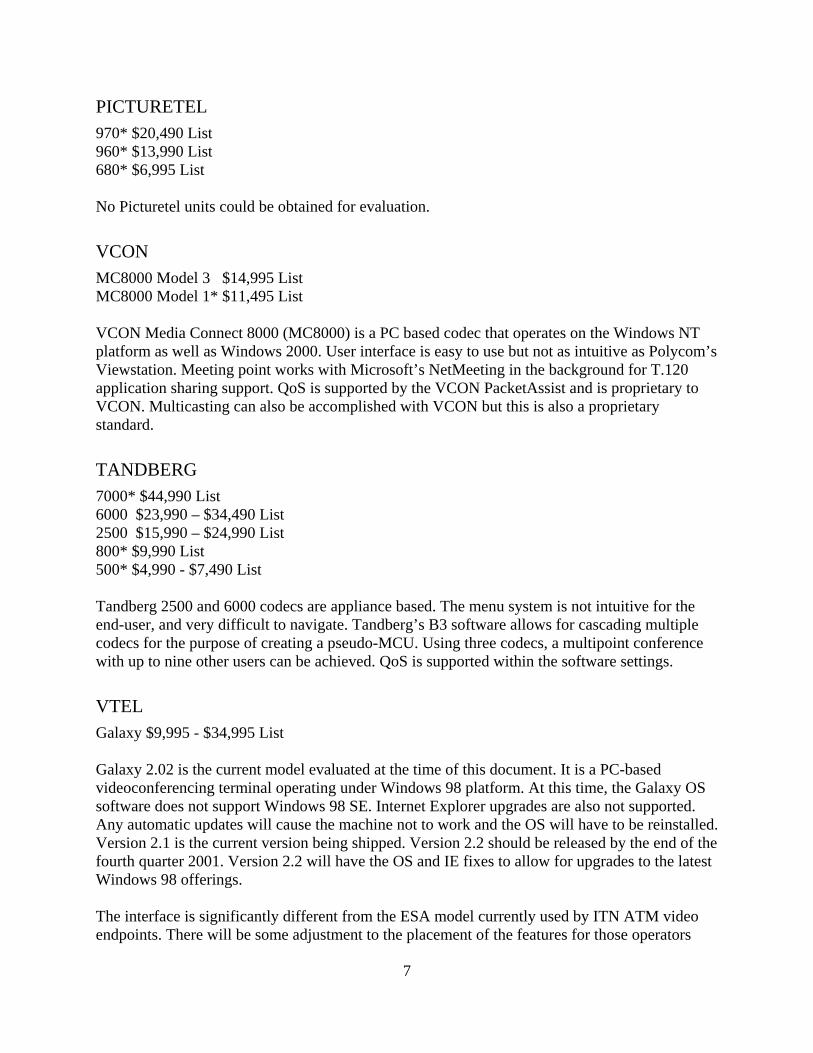
PICTURETEL 970* $20,490 List 960* $13,990 List 680* $6,995 List No Picturetel units could be obtained for evaluation.
VCON MC8000 Model 3 $14,995 List MC8000 Model 1* $11,495 List VCON Media Connect 8000 (MC8000) is a PC based codec that operates on the Windows NT platform as well as Windows 2000. User interface is easy to use but not as intuitive as Polycom’s Viewstation. Meeting point works with Microsoft’s NetMeeting in the background for T.120 application sharing support. QoS is supported by the VCON PacketAssist and is proprietary to VCON. Multicasting can also be accomplished with VCON but this is also a proprietary standard.
TANDBERG 7000* $44,990 List 6000 $23,990 – $34,490 List 2500 $15,990 – $24,990 List 800* $9,990 List 500* $4,990 - $7,490 List Tandberg 2500 and 6000 codecs are appliance based. The menu system is not intuitive for the end-user, and very difficult to navigate. Tandberg’s B3 software allows for cascading multiple codecs for the purpose of creating a pseudo-MCU. Using three codecs, a multipoint conference with up to nine other users can be achieved. QoS is supported within the software settings.
VTEL Galaxy $9,995 - $34,995 List Galaxy 2.02 is the current model evaluated at the time of this document. It is a PC-based videoconferencing terminal operating under Windows 98 platform. At this time, the Galaxy OS software does not support Windows 98 SE. Internet Explorer upgrades are also not supported. Any automatic updates will cause the machine not to work and the OS will have to be reinstalled. Version 2.1 is the current version being shipped. Version 2.2 should be released by the end of the fourth quarter 2001. Version 2.2 will have the OS and IE fixes to allow for upgrades to the latest Windows 98 offerings. The interface is significantly different from the ESA model currently used by ITN ATM video endpoints. There will be some adjustment to the placement of the features for those operators
8
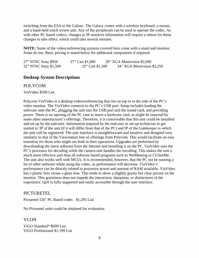
switching from the ESA to the Galaxy. The Galaxy comes with a wireless keyboard, a mouse, and a hand-held touch screen unit. Any of the peripherals can be used to operate the codec. As with other PC based codecs, changes to IP sensitive information will require a reboot for those changes to take effect, which could take several minutes.
NOTE: Some of the videoconferencing systems covered here come with a stand and monitor. Some do not. Basic pricing is stated below for additional components if required. 27” NTSC Sony $950 27” Cart $1,000 29” XGA Monivision $2,000 32” NTSC Sony $1,500 32” Cart $1,100 34” XGA Monivision $3,250
Desktop System Descriptions
POLYCOM ViaVideo $599 List Polycom ViaVideo is a desktop videoconferencing that sits on top or to the side of the PC’s video monitor. The ViaVideo connects to the PC’s USB port. Setup includes loading the software onto the PC, plugging the unit into the USB port and the sound card, and providing power. There is no opening of the PC case to insert a hardware card, as might be required by some other manufacturer’s offerings. Therefore, it is conceivable that this unit could be installed and set up by the end-user. Information required by the end-user or set-up technician to get started is: IP of the unit (if it will differ from that of the PC) and IP of the Gatekeeper to which the unit will be registered. The user interface is straightforward and intuitive and designed very similarly to that of the Viewstation line of offerings from Polycom. This would facilitate an easy transition for those who might use both in their operations. Upgrades are performed by downloading the latest software from the Internet and installing it on the PC. ViaVideo uses the PC’s processor for decoding while the camera unit handles the encoding. This makes the unit a much more effective unit than all software based programs such as NetMeeting or CUSeeMe. The unit also works well with MCUs. It is recommended, however, that the PC not be running a lot of other software while using the codec, as performance will decrease. ViaVideo’s performance can be directly related to processor power and amount of RAM available. ViaVideo has a plastic lens versus a glass lens. This tends to show a slightly grainy but clear picture on the monitor. This graininess does not impede the interaction, sharpness, or distinctness of the experience. QoS is fully supported and easily accessible through the user interface.
PICTURETEL Picturetel 550* PC Based codec. $1,295 List No Picturetel units could be obtained for evaluation.
VCON ViGO Standard* $699 List ViGO Professional $1,199 List

9
ViGO Executive* $1,995 List Cruiser 150* $1,295 List Cruiser 384 $2,995 List Cruiser Executive* $4,995 List Escort 25 $899 List VCON has three products in the desktop arena. All VCON products are PC hardware codecs. The Escort and Cruiser require one PCI slot. The ViGO has its own base that connects to the PC via USB. All cameras are glass lens. The cameras sit either on top of the monitor or on top of the ViGO base. All VCON products come with VCONs PacketAssist QoS technology and multicasting capability. Depending on type of model purchased, the microphone will be incased in the camera or as an optional tabletop microphone. Installation is straightforward by inserting a CD and then following the instructions. Inserting the IPs for the gatekeeper and the system the unit is running on is done during setup. When changes are made, the software must be restarted for the changes to take effect. NOTE: Expanded views of Table 1 and Table 2 can be seen in Appendix C and D respectively. Appendix E has a synopsis of codec cost (List Price) by vendor.

10
Table 1 Comparison of Desktop Videoconference Terminals by Vendor Model
Shaded region indicates a corresponding room system in that product line. ViGo Escort/Cruiser ViaVideo PICTURETELH.320 – ISDN X X H.323 – IP X X X X
H.281 - Far end camera control X X X H.261 - Video codec for audiovisual services at p x 64 kpbs X X X X
H.263 - Video coding for low bit rate communication
X X X X
G.711 - Pulse code modulation (PCM) of voice frequencies X X X X
G.722 - 7 kHz audio-coding within 64 kbps
X X X X
G.728 - Coding of speech at 16 kbps using low-delay code excited linear prediction
X X X X
Acoustic Echo Cancellation (AEC) X X X X Automatic Gain Control (AGC) X X X
T.120 - Data protocols for multimedia conferencing
X X X X
Quality of Service (QoS) X X X Frames per Second: fps 30 30 30 30 Windows 98 X X X X Windows NT X X Windows 2000 X X X X Windows ME X X X Processor P II P P with MMX P II
Max Lan Speed 1.5 Mbps 1.5 Mbps 384 384 - ISDN 768
- IP USB or Card (ISA/PCI) USB PCI USB PCI* Camera (Manual/PTZ) Both Both Manual Manual *One free PCI slot **Unit in degrees

11
Table 2 Comparison of Room System Codecs by Vendor
Shaded Region indicates a corresponding desktop system in that product line. VCON POLYCOM PICTURETEL TANDBERG VTEL
MC8000ViewStation
FX 600 900 2500 6000 GalaxyH.320 – ISDN X X X X X X X H.323 – IP X X X X X X X
H.281 - Far end camera control X X X X X X X H.261 - Video codec for audiovisual services at p x 64 X X X X X X X
H.263 - Video coding for low bit rate communication X X X X X X X
G.711 - Pulse code modulation (PCM) of voice frequencies X X X X X X X
G.722 - 7 kHz audio-coding within 64 kbps X X X X X X X
G.728 - Coding of speech at 16 kbps X X X X X X X
Acoustic Echo Cancellation X X X X X X
Automatic Gain Control X X X X X T.120 - Data protocols for multimedia conferencing X X X X X X X
Quality of Service (QoS) X X X X
Frames per Second: fps 30 30* 30* 30 30 30
Windows NT X X
Windows 2000 X X
Camera (Fixed/PTZ) PTZ PTZ PTZ PTZ PTZ PTZ PTZ Focus/Brightness/ White Balance Auto Auto Auto or
Manual Auto or Manual Auto
VISCA camera support X X X X X Voice activated camera positioning X X X
Built-in MCU CAPABILITY X X X
Max Lan Speed 1.5 Mbps 2 Mbps 2 Mbps
Web access for control of codec X X
X
*30 fps at 256Kbps and above **Units in degrees
12
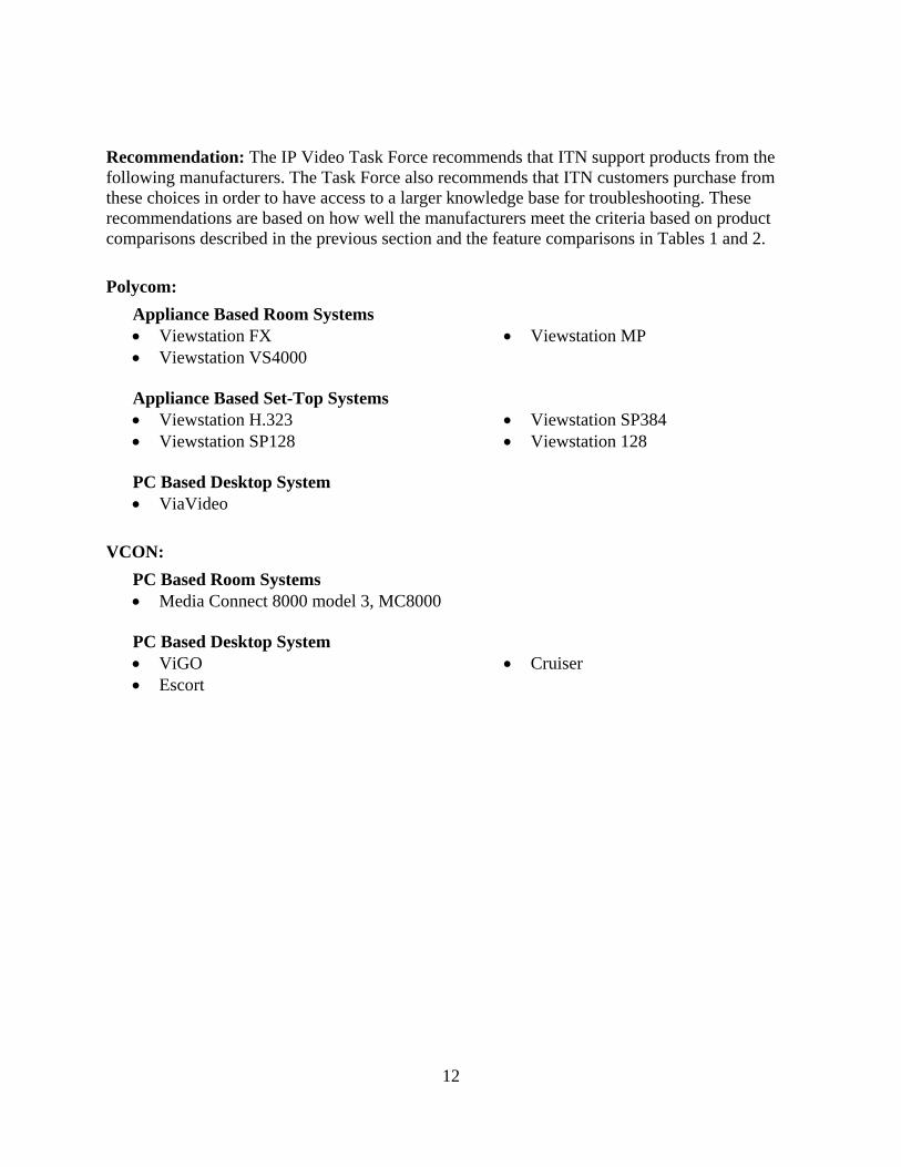
Recommendation: The IP Video Task Force recommends that ITN support products from the following manufacturers. The Task Force also recommends that ITN customers purchase from these choices in order to have access to a larger knowledge base for troubleshooting. These recommendations are based on how well the manufacturers meet the criteria based on product comparisons described in the previous section and the feature comparisons in Tables 1 and 2. Polycom:
Appliance Based Room Systems • Viewstation FX • Viewstation VS4000
• Viewstation MP
Appliance Based Set-Top Systems • Viewstation H.323 • Viewstation SP128
• Viewstation SP384 • Viewstation 128
PC Based Desktop System • ViaVideo
VCON:
PC Based Room Systems • Media Connect 8000 model 3, MC8000
PC Based Desktop System • ViGO • Escort
• Cruiser

13
H.323 Multipoint Conference Unit (MCU)
The Multipoint Conference Unit (MCU) is an important part of an H.323 videoconferencing infrastructure, allowing three or more parties or persons to get together in a virtual meeting room. PRIMARY QUESTIONS
• What is an MCU? • Why do we need an MCU? • Can an MCU create conferences with endpoints using different protocols? • Should I use a third-party scheduler or an internal scheduling device on the MCU?
ANSWERS What is an MCU? Like the more familiar audioconference bridge, an MCU essentially creates a point-to-point videoconference with each endpoint within a given conference. An MCU uses sophisticated software and hardware to combine these inputs into a shared environment very like a physical meeting space. Why do we need an MCU? An MCU is required to link three or more endpoints. Can an MCU create conferences with endpoints using different protocols? Depending on the type of MCU purchased, this can be accomplished. The Accord MCU is able to transcode between protocols. Other MCUs require the assistance of an external gateway to transcode between protocols. Should I use a third-party scheduler or an internal scheduling device on the MCU? Depending upon the particular vendor’s MCU, the scheduler function may not have everything that the scheduling operator wants or needs. Not all internal schedulers can control other types of MCUs, whereas a third party scheduler can do so. As with most every technology, the more a product can do, the more expensive it is. Multipoint Conference Unit Testing IHETS tested four H.323 MCUs from February through March 2001: Accord – MGC-100; Cisco – 3540 MCU; Ezenia – Encounter 3000; CUSeeMe – Whitepines. Each MCU was tested over a three-day period with participants from higher education, K-12 education, and libraries. The participants were: Higher Education: Ball State University
Indiana State University Indiana University Ivy Tech State College – Ft. Wayne Purdue University
K-12 Schools: East Central Educational Service Center
Northern Indiana Educational Service Center
14
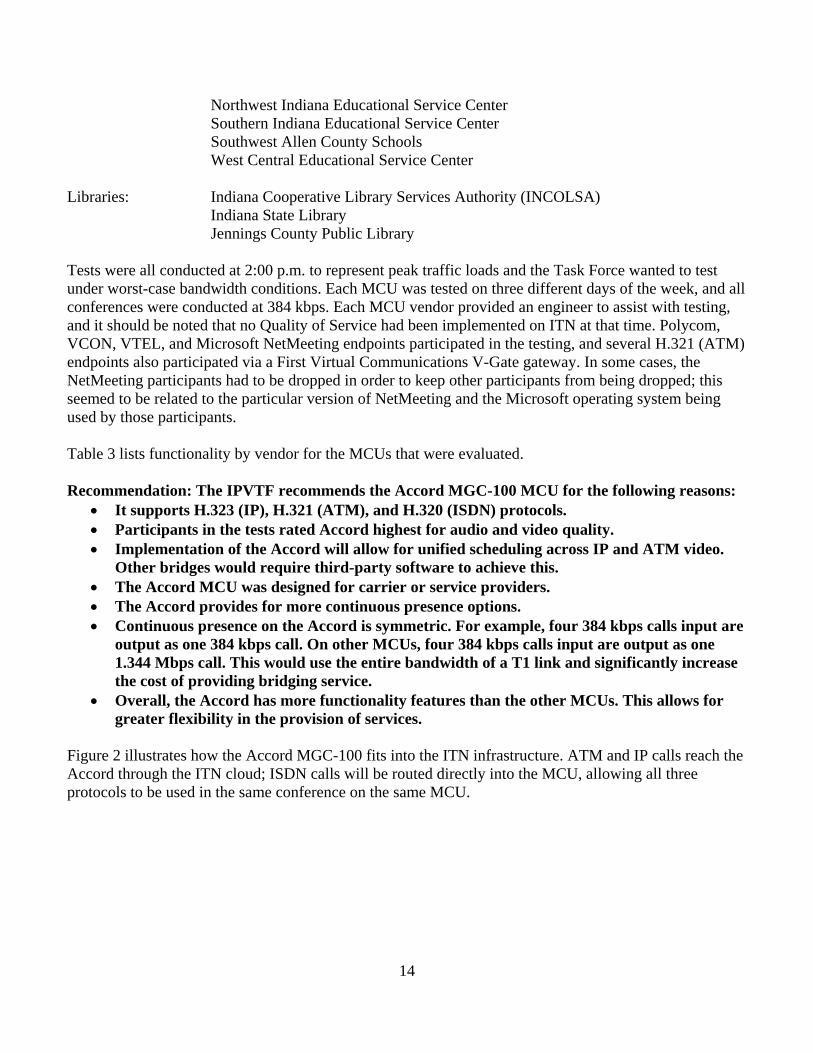
Northwest Indiana Educational Service Center Southern Indiana Educational Service Center Southwest Allen County Schools West Central Educational Service Center
Libraries: Indiana Cooperative Library Services Authority (INCOLSA)
Indiana State Library Jennings County Public Library
Tests were all conducted at 2:00 p.m. to represent peak traffic loads and the Task Force wanted to test under worst-case bandwidth conditions. Each MCU was tested on three different days of the week, and all conferences were conducted at 384 kbps. Each MCU vendor provided an engineer to assist with testing, and it should be noted that no Quality of Service had been implemented on ITN at that time. Polycom, VCON, VTEL, and Microsoft NetMeeting endpoints participated in the testing, and several H.321 (ATM) endpoints also participated via a First Virtual Communications V-Gate gateway. In some cases, the NetMeeting participants had to be dropped in order to keep other participants from being dropped; this seemed to be related to the particular version of NetMeeting and the Microsoft operating system being used by those participants. Table 3 lists functionality by vendor for the MCUs that were evaluated. Recommendation: The IPVTF recommends the Accord MGC-100 MCU for the following reasons:
• It supports H.323 (IP), H.321 (ATM), and H.320 (ISDN) protocols. • Participants in the tests rated Accord highest for audio and video quality. • Implementation of the Accord will allow for unified scheduling across IP and ATM video.
Other bridges would require third-party software to achieve this. • The Accord MCU was designed for carrier or service providers. • The Accord provides for more continuous presence options. • Continuous presence on the Accord is symmetric. For example, four 384 kbps calls input are
output as one 384 kbps call. On other MCUs, four 384 kbps calls input are output as one 1.344 Mbps call. This would use the entire bandwidth of a T1 link and significantly increase the cost of providing bridging service.
• Overall, the Accord has more functionality features than the other MCUs. This allows for greater flexibility in the provision of services.
Figure 2 illustrates how the Accord MGC-100 fits into the ITN infrastructure. ATM and IP calls reach the Accord through the ITN cloud; ISDN calls will be routed directly into the MCU, allowing all three protocols to be used in the same conference on the same MCU.

15
Figure 2
ISDN
W orkstation
Client(IP)
Client(IP)
Gatekeeper
Accord MCUIP
ISDNATM
48 Ports
Ezenia MCUISDNA TM
32 Ports
Radvis ionGatew ay
Radvision3510MCU
317317317
xxx-xxxxxxx-xxxxxxx-xxxx
ATM
ATM
ATM
ATM
Gatekeeper
Gatekeeper
Gatekeeper
PRI Circuit 107
PRI Circuit 108PR
I Circ
uit 1
05PR
I Circ
uit 1
06
New
PR
I Circ
uit
IHETS MainDirectory GK
Cluster
IP
IP
V I DEOS ERVER
MCS
V-Ga te
V-Gate
V-Ga te
V-Gate
I2
Internet
IP
IP
IP
IP
IP
IP
IPRASRAS
RAS
RAS
RAS
RAS
RAS
ITN
STBY
FAIL
AC
TIVE
STBY
FAIL
AC
TIVE
STBY
FAIL
ACTIVE
STBY
FAIL
ACTIVE
STBY
FAIL
AC
TIVE
STBY
FAIL
AC
TIVE
STBY
FAIL
AC
TIVE
STBY
FAIL
ACTIVE
STBY
FAIL
ACTIVE
STBY
FAIL
AC
TIVE
STBY
FAIL
AC
TIVE
STBY
FAIL
AC
TIVE
STBY
FAIL
ACTIVE
Net
MPI
M G3 23
V i de o
M UX
V i de o
V i de o
A UDI O
A UDI O
D AT A
Data
A ud i o
A ud i o
L1L2 L
3
Power
PWRI N
OUT
PWRI N
OUT
PWRI NOUT
MGC-
100
IP
GG
GG
GGGG
GG
W orkstation

16
Table 3 COMPANY/PRODUCT ACCORD CISCO EZENIA! 1st VirtualFunction (Capability) Supported MGC 100 RADVSION ENCOUNTER CUSeeMe 3540 3000 Video Coding H.261 X X X X H.263 X X X X Audio Coding G.711 X X X X G.722 X X G.723 X G.728 X Data Collaboration T.120 (out-of-band) X X X Gateway required for ATM, ISDN calls X X X Multi-way Transcoding (audio and video)* X Audio Auto-detection of protocol X Voice Activated Switching X X X X Continuous Presence (Quad split) X X X X Continuous Presence (Other layouts) X (16) Cascading X X X Internal Scheduling Software X X X 3rd party scheduling software available X X X X System management via Web access X X X X Scheduling Web accessible X X X *Transcoding is the capability to automatically change video and/or audio from one protocol to another.

17
Gatekeeper Topology
The topology, or layout, of gatekeepers in an H.323 system determines how calls are routed throughout the network and affects how dial plans may be implemented. This makes the gatekeeper a fundamental device in an H.323 network. No special services such as multipoint conferencing or gateways to the public network can be accessed without registering with a gatekeeper. PRIMARY QUESTIONS
• What is a gatekeeper? • Why do I need a gatekeeper? • What is the gatekeeper topology required to accomplish a cross-zone dial plan?
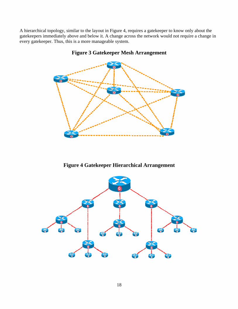
ANSWERS What is a gatekeeper? The gatekeeper is the brain of an H.323 network, performing essential control, administrative, and managerial functions. However, the gatekeeper does not route any data packets in a network. These continue to rely on standard network routing equipment. The primary purposes of a gatekeeper are address translation and zone administration using layer three of the OSI model. Why do I need a gatekeeper? Without a gatekeeper, there would be no technical control over use of resources on a network. End-users could strain links and traffic load by placing video calls at 768 kbps throughout the network. Even with Quality of Service enabled, if there is not enough bandwidth to handle the calls, the calls would be of poor quality or fail altogether. Further, an end-user would not be able to dial other end-users by their identities. End-users could only be accessed using their IP addresses. What is the gatekeeper topology required to accomplish a cross-zone dial plan? A hierarchical gatekeeper structure will reduce administrative complexity for both ITN and the endpoints. This hierarchy allows assignment of different zone dialing prefixes if required. (Alternatives are described more fully below.) Recommendation: The IPVTF recommends that ITN adopt a hierarchal gatekeeper plan, which will consist of a “Main Directory” gatekeeper, “Zone” gatekeepers, and “Institutional” gatekeepers. This will allow the implementation of a multi-zone dial plan and also reduce administrative complications that the alternative mesh network would require. Gatekeeper Topology Gatekeeper Topology Types There are two major topologies for a gatekeeper network: mesh and hierarchical. A mesh network requires every gatekeeper in the network to know about every other gatekeeper on the entire network, as can be seen in Figure 3. This is accomplished within the gatekeeper using a table of neighbor gatekeepers. As the network changes and grows, this table needs to be updated in every single gatekeeper on the network. In a large network, this can be an administrative nightmare.
18
A hierarchical topology, similar to the layout in Figure 4, requires a gatekeeper to know only about the gatekeepers immediately above and below it. A change across the network would not require a change in every gatekeeper. Thus, this is a more manageable system.
Figure 3 Gatekeeper Mesh Arrangement
GG
GG
GG
GG
GG
GG
Figure 4 Gatekeeper Hierarchical Arrangement
GG
GG
GG GG GG
GG GG GG
GG
GG GG GG
GG
GG GG GG
GG
GG GG GG
GG
GG GG GG

19
Recommended Hierarchical
Gatekeeper Topology
Muncie
Fort Wayne
Portage
South Bend
Lafayette
Evansville
Bloomington
Columbus
Louisville GG
Gatekeeper
GGGatekeeper
GGGatekeeper
G G Gatekeeper
GGGatekeeper
GGGatekeeper
G G Gatekeeper
GGGatekeeper
GGGatekeeper
GG
InstitutionalGatekeeper
G
InstitutionalSub-gatekeeper
GInstitutionalSub-gatekeeper
G
InstitutionalGatekeeper
G
InstitutionalSub-gatekeeper
GInstitutionalSub-gatekeeper
G
Main Directory Gatekeeper
Cluster
Client Terminal Client Terminal
Institution’s ClientTerminal
G G Gatekeeper
Institution’s ClientTerminal
InstitutionalGatekeeper
G
InstitutionalSub-gatekeeper
GInstitutionalSub-gatekeeper
G
Client Terminal
Client Terminal
Client Terminal
Client Terminal
219
574
260
765
812
317
Hierarchical Gatekeeper Structure The IPVTF determined that a hierarchical gatekeeper structure was the best method to implement for ITN. The gatekeepers used in this hierarchy would have the following requirements:
• Support for gatekeeper clustering for redundancy
• Compatibility with existing network infrastructure and H.323 endpoints
• Support for location request (LRQ) forwarding
• LRQ forwarding needs to forward across multiple gatekeepers
• LRQ forwarding must support at least four levels of hierarchy
Given this set of criteria for gatekeepers, the Dial Plan Committee put together a recommended gatekeeper topology. The topology starts with a primary directory gatekeeper or gatekeeper cluster. Clustering is a method of using multiple gatekeepers to increase capacity and redundancy. It would also offer scalability, since call volume will be low to begin with and increase as time goes by. Fanning out from this directory gatekeeper cluster are sub-gatekeepers. These sub-gatekeepers would be placed at each of the ITN major nodes and allow registration from ITN customers who may not have their own gatekeeper. These sub-gatekeepers would have a dialing prefix matching the area code of their location. Larger institutions that wish to install their own gatekeeper should choose to install a directory gatekeeper. This gatekeeper would be “neighbored” to the ITN main directory gatekeeper. Sub-gatekeepers operated by the entity would be set up below their directory gatekeeper in the hierarchy.
This plan allows for three total levels of hierarchy including two levels for a large entity and two levels for ITN (due to the fact that the level immediately below the main directory gatekeeper will
Figure 5

20
have some ITN gatekeepers and some institutional gatekeepers). A fourth level, which would be above ITN, could be used in the future for participation in a national network. Recommended Topology A drawing of the recommended gatekeeper topology is displayed in Figure 5. The drawing is simplified for clarity, as there would obviously be many more client terminals as well as institutions with their own gatekeepers. The main points to be conveyed with the drawing are as follows:
• There is a central redundant directory gatekeeper cluster, which is the central point of control for the entire state.
• No terminals are registered with the Main Directory Gatekeeper. • Attached to this Main Directory Gatekeeper are the ITN Node Gatekeepers. • Node Gatekeepers are placed at the various nodes of the network and will have dialing
prefixes to match their respective area codes. • Node Gatekeepers can accept registration from terminals. • Institutions can have their own Directory Gatekeeper to service their own sub-gatekeepers
attached to nodes of their own internal networks. • Institutions’ Directory Gatekeepers will be connected directly to the ITN Main Directory
Gatekeeper. • Terminals will register with the gatekeepers using Registration Admission Status (RAS)
protocol. Using gatekeepers for address resolution allows terminal endpoints to be configured for dynamic IP address allocation (DHCP). Terminals can literally be taken around the world and installed on any network. As long as terminals are registered with the same gatekeeper, they can be dialed using the same method as if they were at home. This is not unlike “roaming” in a mobile telephone arrangement.
This gatekeeper topology requires no more than three levels of hierarchy for the entire state. Given the current state of LRQ forwarding support within gatekeepers, only four total levels of hierarchy could be supported. This may change in the future, allowing a larger hierarchical structure. At this time, using three levels for the state leaves an additional level to allow participation in a larger network with other states.

21
Support for Gateways The gateway is another fundamental device in an H.323 network. Without the gateway, there could be no cross-technology communication. Some may mistakenly interchange the terms “gateway” and “gatekeeper,” but they are very different devices. PRIMARY QUESTIONS
• What is a gateway? • Why do I need a gateway? • What connections does ITN need for a gateway?
ANSWERS What is a gateway? A gateway allows different protocols to talk to each other through the translation of IP protocol to ISDN protocol and vice versa. This device allows an ISDN unit to call an H.323 unit and vice-versa or an H.323 unit to communicate with an ATM video unit. To perform this function, a gateway acts as a transcoder from one type of technology to another. Transcoding may involve changing the physical transport medium of the data being delivered as well as the protocols. Why do I need a gateway? A gateway is a translator, allowing the end-user to communicate with other end-users that use different voice, video, and data protocols. What connections does ITN need for a gateway? A gateway would require an IP connection to the network for H.323 communications, typically a 10Mbps connection at full duplex. For an ISDN gateway, connection to the PSTN would consist of a PRI line with 24 64Kbps channels. Smaller ISDN gateways are available and would use multiple ISDN lines instead of a PRI. An ATM gateway would require an ATM interface to the ATM network. Recommendation: The IPVTF recommends the purchase of a Radvision L2W-323 PRI gateway. Importance of Gateways Gateways are important because they let H.323 users continue to use legacy devices until sufficient resources become available to replace outdated hardware. In addition, many endpoints operated by commercial enterprises are still ISDN-based and will most likely continue to remain in service until the nationwide commercial IP network attains enough robustness to support two-way video. The Radvision gateway, together with the existing V-GATE gateways, will give ITN the flexibility it needs to accommodate existing ISDN and ATM video codecs. All incoming gateway calls would come into a 317 area code. From there, a routing hierarchy using DID, TCS4, Interactive Voice Response, and Default Routing will be employed to route calls to their appropriate H.323 endpoint according to the dial plan set forth later in this document.

22
IP Voice/Video Dial Plan
The IPVTF set out to create a dial plan that would be familiar to users, easy to learn, and feasible to implement on the H.323 network using currently available hardware. PRIMARY QUESTIONS
• Why do I need a “Dial Plan”? • What is E.164 Addressing? • What is an H.323 alias? • Should Direct Inward Dial (DID) assignments be used for all H.323 endpoints to allow
access from H.320 endpoints, using a unique North American Numbering Plan (NANP) assignment?
• Should E.164 compatible numbers be used for the H.323 endpoints, or should domain/alias addressing be used instead?
• What are the implications of these choices for cross technology dialing? • What are the implications for IP voice telephony? • Should existing telephone area codes be used or does ITN choose unique prefixes? • What is the best method to interface with special equipment such as gateways and
multipoint conference units (MCUs)? ANSWERS Why do I need a “Dial Plan”? A dial plan allows for a standardized format in assigning an identity to an end-user. A dial plan defines the style of the unique identity as well as how to implement it. A direct comparison can be made to the way we dial a telephone today. The telephone company assigns each end-user a unique number. Without that unique number, an end-user could decide to have a new phone number every day or decide to dial a number that does not belong to the end-user that is being called, thus making it very difficult for one person to reach another. What is E.164 Addressing? E.164 Addressing, an ITU-T standard, is the international public telecommunication numbering plan. This standard allows the ITN to use numbers such as a desk phone for a video conferencing endpoint. With this type of addressing, a number string made up of 0 through 9 can be 15 numbers long. This provides the ability to make each end point unique. What is an H.323 alias? An alias is another way to describe who an end-user is. This alias can be made from alphanumeric characters, numbers, or both. Some examples of an H.323 alias are: 157913132; Pcom; brickhouse; State Library 2. Should Direct Inward Dial (DID) assignments be used for all H.323 endpoints to allow access from H.320 endpoints, using a unique North American Numbering Plan (NANP) assignment? After evaluating the current rate of off-network inbound and outbound activity, the Task Force determined that some H.323 endpoints would require or desire a NANP assignment for their terminal. IP voice telephony considerations might make that even more necessary since much of

23
the voice traffic would be off network. However, the expense of NANP assignments for all units and all area code groups may be cost-prohibitive. While DID support is important, due to cost constraints, not all H.323 endpoints may be able to have a NANP number association. Should E.164 compatible numbers be used for the H.323 endpoints, or should domain/alias addressing be used instead? Based on research of other entities with dial plans, the Task Force first considered support for both domain/alias routing and E.164 number assignments. Due to cross-technology considerations as well as off-network calling, the group eventually decided that E.164 should be the only supported method of dialing. What are the implications of these choices for cross technology dialing? There would be no support for off-network dialing or call reception if domain/alias were the only dialing format supported. Current ATM terminals would need to be abandoned immediately, instead of allowing a technology transition period. Off-network inbound and outbound calling would be nonexistent or extremely cumbersome. What are the implications for IP telephony? If ITN uses only a domain/alias dialing scheme, there would be no support for the current IP telephones. Should existing area codes be used or does ITN choose unique prefixes? Most members of the task force felt that using existing area codes would provide a feeling of familiarity to the technology, since most users have been using the area codes all of their lives. This is also required for DID compatibility for endpoints assigned a NANP number. What is the best method to interface with special equipment such as gateways and multipoint conference units (MCUs)? Some sort of technology prefix, included in the dial string, is needed to indicate that the call should be routed off network or to an MCU. Design Goals
• The dial plan should be compatible with legacy H.320 ISDN and H.321 ATM videoconferencing endpoints.
• The plan should support E.164 numbers to allow H.323 endpoints to appear as PSTN terminals using DID with NANP allocations.
• The plan should accommodate gateway TCS4 signaling to route calls to endpoints not assigned a DID number.
• The plan should allow support for older style H.320 codecs that do not support TCS4 signaling.
• The dial plan should allow zone administrators to choose their own dialing extensions for endpoints not associated with a DID number.
• The dial plan should keep an eye toward the future convergence of packet based and PSTN technologies.
• The dial plan should support user mobility. Users should be able to relocate their terminal anywhere in the state and not be required to change the numbers used to dial into their codecs.

24
Recommendations: The IPVTF recommends that: • The dial plan take the form of: E[*T]ZZZNNNNNNN; where E = Exit zone;
*T = Technology prefix; Z = Area code; and N = 7 digit dialing extension number • The dial plan support ISDN codecs that have specific circuit restrictions through the
use of Technology prefixes • A PRI be purchased to support “ISDN off net” to “IP on net” Point-to-Point calls • An ISDN to IP gateway be purchased to support “ISDN off net” to “IP on net”
Point-to-Point calls The Dial Plan Determining the gatekeeper topology allowed development of a dial plan. Based on answers to the primary questions discussed earlier, the IPVTF decided to fully support DID. Due to the cost of NANP assignments, both direct expense and administrative costs, it would be impractical to provide NANP assignment for every H.323 endpoint on the network. A limited number of H.323 endpoints will be able to obtain a NANP assignment; other sites will be supported using TCS4 and other methods of call routing from an inbound ISDN call. Compatibility with existing ATM platforms, as well as support for out-of-network dialing to and from legacy H.320 ISDN based systems, is still required. One of the options seriously considered by the IPVTF was the concept of domain/alias dialing, similar to the e-mail system currently in use by millions. An example of this kind of dialing would be user 1 dialing user 2, who is connected to the Lafayette network node by dialing: [email protected] or possibly: user2.Lafayette.ihets.org. One can see the simplicity of this scheme. Unfortunately, to ensure compatibility with all gatekeepers, ATM endpoints, off-network H.320 terminals, and IP phones, an alphanumeric dialing scheme is simply not feasible. Even ViDeNet, one of the largest H.323 gatekeeper networks, is expected to change its position regarding endorsement of domain/alias dialing. The IPVTF also considered a dual method using both domain/alias and E.164. Again, the feasibility of this task given the current state of gatekeepers would prohibit this type of system from being implemented easily. Structure The structure of the dial string will be based upon the NANP system, although number assignments will be internal to the network. Exceptions would be cases where endpoints wish a true NANP assignment for DID support. The structure of the dial string will be as follows:
E[*T]ZZZNNNNNNN Where: E=Exit Zone Prefix. This will typically be a “1” as defined by the dial plan. “1” was chosen because it reminds users that they are making a long distance call. This will preclude users from

25
using local E.164 extensions beginning with “1” due to the method gatekeepers use to parse the string. The gatekeeper would match the “1” and immediately assume it is an out of zone call. T=Technology Prefix. This will be an optional prefix not required in the dial string. It is a prefix that can only be used by H.323 endpoints. It will be used to force call routing to take a particular path, such as calling out via ISDN to an off-network endpoint. Sometimes, this code is known as a service prefix. Since this is an optional prefix, we have proposed the use of “*” as a delimiter in the string. The delimiter will ensure that the technology prefix does not get confused with a digit in an area code. Here is the proposed list of technology prefixes:
*9 – This will be the designation for a single channel off-network voice-only call. “9” was chosen because it is a typical code to get an outside line, especially in Centrex style systems. *6 – This will be the designation for a 6-B channel off-network video call consisting of 6 64KB ISDN B channels aggregated to 384K using the Bonding Mode 1 Protocol. *2 – This will be the designation for a 2-B channel off-network video call consisting of 2 64KB ISDN B channels aggregated to 128K using the Bonding Mode 1 Protocol. *3 – This will be the designation for a 2-B channel off-network video call consisting of 2 64KB ISDN B channels, dialed separately, and restricted to 56K data rates.
ZZZ=area code. This is the area code the user endpoints are assigned. It will also assist the gatekeepers in routing the call to the correct endpoint and allow seven-digit extension reuse among area codes in the future. NNNNNNN=the seven digit dialing extension for the end point. All endpoint extensions will be seven digits. The seven-digit extension should be the only dialing string necessary for dialing within a gatekeeper zone. Dialing Examples Given an H.323 terminal registered to a gatekeeper located in the 765 area code, with a dialing extension of 4961234, here are some examples describing how to dial into that terminal. Examples 1-4 ONLY apply to inward dialing from an ISDN type endpoint trying to connect to an H.323 endpoint. Examples 5-7 demonstrate point-to-point calls from H.323 endpoints on the network. Example 8 demonstrates how an ATM endpoint on the network would dial an H.323 endpoint. 1. H.320 unit to an H.323 endpoint using DID where the H.323 endpoint has a NANP assignment:
317 496 1234

26
Notice that the area code for this unit is 317 instead of 765. Due to cost constraints involved in having NANP numbers outside the 317 area code to appear at the ITN Gateway, all codecs wishing to have DID support using a NANP assignment will be required to register with the 317 area code gatekeepers. However, the unit may still be physically located outside the 317 area code. An H.323 endpoint cannot be assigned more than one area code; therefore this unit will only be dialed using a 317 area code, no matter whether the call is on- or off-network.
2. H.320 unit to an H.323 endpoint with no DID assignment from a newer TCS4 capable codec:
317 555 1234 ## 765 496 1234 Where 317 555 1234 is the access number and ## is the delimiter used by the codec. (This delimiter may vary from codec to codec.)
3. H.320 unit to an H.323 endpoint with no DID assignment from a non-TCS4 capable codec:
317 555 1234 (Access Number) Wait for the voice response, then enter the extension number (765 496 1234) using a DTMF keypad
4. H.320 unit to an H.323 endpoint with no DID assignment from a non-TCS4 and non-DTMF capable codec:
317 555 1234 (Access Number) After voice response gets no DTMF tones, the call is routed to an available MCU. The receiving party will also be required to make a connection to the MCU, meaning this will be a prearranged meeting.
5. H.323 to H.323 registered with the same gatekeeper:
496 1234
6. H.323 to H.323 in same area code but not same gatekeeper: 1 765 496 1234
7. H.323 to H.323 across area codes:
1 765 496 1234 8. ATM endpoint to H.323 Terminal:
765 496 1234
Technology Prefix Examples The following examples demonstrate how to use technology prefixes to make off-network calls. 1. To make a 384K Video Call to an ISDN H.320 endpoint with a dialup number of 812 883 1234 from a H.323 endpoint on the network:
1*6 812 883 1234

27
2. To make a dual channel 56K call from an H.323 endpoint to an endpoint where both B channels of the ISDN line have the same dialup number:
1*3 812 883 1234 3. To make a dual channel 56K call to an endpoint where B channels of the ISDN line have different dial up numbers. NOTE: The comma is a delimiter set up in the gateway. The comma was chosen since it can only be dialed by newer IP based codecs such as Polycom, VCON, and Zydacron.
1*3 812 883 1234, 812 883 1235 4. To make a voice only call to someone’s desk telephone from an H.323 endpoint:
1*9 317 263 8888 Dial Plan Key Points
• All H.323 endpoints will be registered with an ITN gatekeeper or their institutions gatekeeper using RAS. The institutions gatekeeper will be neighbored with the ITN Main Directory Gatekeeper.
• H.323 endpoints will be assigned an E.164 compatible number to use as their H.323 dialing extension.
• Some H.323 terminals may be given NANP assignments to allow direct inward dialing from the PSTN.
• H.323 terminals will be assigned an area code based on their geographic location. These area codes will be the same as their current geographic area code. The exception to this will be devices with a NANP assignment, as these assignments will all have a 317 area code.
• System administrators operating their own gatekeepers will be allowed to assign their own extension numbers as long as they follow the ITN dial plan and coordinate the numbers with ITN to avoid duplications across the network.
• The dial plan will support technology prefixes but will not require them. Technology prefixes will be used to force call routing in case of network congestion or malfunction.
• Inbound calls from the PSTN will first be routed by DID. If no match, then TCS4 will be used. If no match, the caller is sent to an interactive voice response (IVR) and prompted to enter the extension they wish to connect to. If the IVR gets no response, the call will be routed to an MCU where the receiving party may be waiting or can join later.
Because TCS4 is still a relatively new standard, and not all H.320 endpoints would be capable of dialing an extension using IVR, it is the recommendation of the IPVTF that all inbound ISDN calls to endpoints not associated with a DID number should be scheduled in advance. This will provide the opportunity to certify and test H.320 endpoints with the gateway before the actual conference occurs.

28
Directory Services
With any type of communication system, there must be a way to find people easily. Directories are familiar and work very well, but the rapid growth and electronic environment of videoconferencing require a new form of Directory Service. THE PRIMARY QUESTIONS
• What is a Directory Service? • Why do I need Directory Service? • What types of Directory Services are available?
ANSWERS What is a Directory Service? A directory service is a collection of databases that store and retrieve information in a user-friendly, accessible manner. The user-friendliness is achieved by developing front-end databases to access the information. It is a complex electronic “phonebook” that scales to accommodate rapid growth. Why do I need Directory Service? Without a directory service, a user would have to contact the person they want to reach to obtain information about how to connect with them. After the exchange of information (gatekeeper address, IP address, E.164 address, and H.323 alias), each party can call the other. This process would have to be repeated for every desired endpoint. Eventually each person would have a large list, becoming at best unwieldy and potentially discouraging use. A directory service solves this problem by having everyone on the network register with it. The administrator enters the appropriate information for each endpoint, which then becomes accessible to all users on the network. What types of Directory Services are available? Several directory services are available. The IPVTF focus on two leaders: Lightweight Directory Access Protocol (LDAP) and First Virtual Communications, Inc., Click to MeetTM (CTM). Recommendation: The IPVTF recommends that First Virtual Communications, Inc., Click to MeetTM be used to provide directory services.
Lightweight Directory Access Protocol (LDAP) LDAP augments the Directory Access Protocol (DAP, RFC 13303) to allow a more efficient search capability than DAP provides. DAP is built using the X.500 protocol, which uses the upper layers of the Open Systems Interconnection (OSI) stack. Advantages of DAP:
• Full-featured, robust directory for recording and displaying information • Global reach

29
Disadvantages of DAP: • Overhead required in using the upper layers of the OSI stack • Highly complex encoding for simple data elements
LDAP was created to simplify the process of creating and maintaining a directory service2, 3. LDAP can be used as a front end to DAP or as a stand-alone server. Creating links to other DAP servers maintains the “Global” function. Based on requirements for a directory, there are several applications that create user-friendliness to inputting and retrieving data. Full details of LDAP can be found in RFC 17774. Timothy Howes, author of, The Lightweight Directory Access Protocol: X.500 Lite, lists four advantages of LDAP over DAP2:
1. LDAP runs over TCP. This reduces the overhead that the OSI Session and Presentation layers require.
2. Simplifies the X.500 model in two ways: a. Leaves out read and write operations and then emulates them through the search
option. b. Leaves out some of the less used security functions of X.500.
3. Uses string encoding for distinguished names and data elements. 4. Frees clients from chasing referrals.
There is no mention in the literature on LDAP, however, about how to integrate a directory service with multimedia applications. Such applications would have to be written specifically for LDAP.
Click to MeetTM (CTM) FVC’s Click to Meet product can be completely integrated into a multimedia environment. While at the time of this document CTM does not integrate with LDAP, there are plans for it to be fully integrated by the end of first quarter of 2002 in version 2.3. By the end of 2001, version 2.2 of CTM should also be able to integrate with Microsoft’s Active Directory.
The front end of CTM utilizes a web interface. CTM works by integrating its database with a gatekeeper to store data and manage bandwidth on calls. The information entered can be as detailed as needed. CTM can tell when an endpoint is or is not available for a call. CTM can then make the connection by having the user select the desired endpoint. Since all the pertinent information has already been entered into CTM (Gatekeeper address, line speed to make the call, etc.), CTM can activate the call the user’s codec is on. If the codec is not on, then it will not have registered with the CTM server/gatekeeper. If the endpoint codec is not on and registered, that endpoint will show up with a “Red X” beside it instead of a “Green Check Mark” on the CTM screen. (See Figure 6.)

30
Figure 6
All Rights ReservedCopyright 2001 – First Virtual Communications, Inc. October 4, 2001 1
Dialing Made SimpleDialing Made Simple
CTM can also initiate an MCU conference by having the person making the call select more than one participant from the CTM address book. CTM can interact with H.320, H.321, and H.323 endpoints. CTM can also be used as a scheduler for prearranged, ad hoc, and point-to-point calls. (See Figure 7.) The user selects the date and time for the call, then selects the participants. At the appointed time, CTM initiates the call. If this is an MCU call (three or more participants), CTM will call the MCU, selecting a service that will fit the conference. If the MCU has the resources, the call will proceed. If the MCU does not have the resources, the call will fail.

31
Figure 7
All Rights ReservedCopyright 2001 – First Virtual Communications, Inc. October 4, 2001 2
Scheduling Made SimpleScheduling Made Simple
CTM can also work with NAT and other firewall software by use of a proxy server. In its paper Click To Meet and NAT/Firewall Solving the Security Dilemma5, FVC outlines four call scenarios:
• A Private CTM to/from a Public Endpoint • A Public CTM to/from a Private Endpoint • A Private CTM to/from a Private CTM • A Private CTM to a Private Endpoint
Other features of CTM can help with security, fault tolerance, scalability, and billing reports6. CTM provides security in the form of authentication. Only authorized users can attach through the CTM servers. Once authenticated, users will then have access to QoS on the network. The user can still place calls without using CTM; however, quality of the call will be lower as there is no bandwidth management and no precedence for video data.

32
Fault tolerance is provided through load balancing by using gateway and MCU resources. CTM can integrate with multiple MCUs, assuring scalability as a network expands.
CTM can also provide billing reports in the form of Call Detail Records (CDR), which can be integrated with third-party billing applications if desired. The CDR can be set up to run either automatically or manually by the administrator.

33
Quality of Service (QoS) No multiservice network can successfully be implemented without being able to provide a QoS or Class of Service (CoS) to preferred services. Due to wide diversity in design of Local Area Networks and Wide Area Networks, each will require its own unique solution. PRIMARY QUESTIONS
• What is QoS? • Why implement QoS? • What creates QoS in H.323? • How does a video call get priority over data traffic? • On which area, WAN or LAN, will a video call be most dependent? • How much bandwidth do I need? • Firewalls and NAT: How do they affect QoS?
ANSWERS What Is QoS? QoS is the set of techniques to manage network resources in a manner that enables the network to differentiate and handle traffic based on policy. This means providing consistent, predictable data delivery to users or applications that are supported within the network. Achieving the required Quality of Service (QoS) by managing delay, delay variation (jitter), bandwidth, and packet loss parameters on a network becomes the secret to a successful end-to-end business solution. Why implement QoS? Implementing a successful QoS policy will ensure a predictable, measurable, and guaranteed treatment of the communications on the backbone. This would provide a better means of handling specialized traffic on the limited and costly backbone resources. The demand for the use of bandwidth-intensive and delay/jitter-sensitive applications coupled with the ever-increasing use of backbone for “unsupported” traffic provides the need and reasoning for implementing QoS. What creates QoS in H.323? There are many tools used to implement QoS in H.323. Some of these are: Differential Services Code Point (DSCP), Resource Reservation Protocol (RSVP), Priority Queuing (PQ), Committed Access Rates (CAR), and Weighted Random Early Detection (WRED), among others. Using many or all of these tools, in conjunction with other technologies, creates a working QoS. Resource Reservation Protocol (RSVP) has been described by some as the magic cure of QoS. At this time, RSVP is being actively developed but is not ready for deployment on core networks. Differential Services Code Point7 (DSCP) is a process that helps to classify or differentiate traffic. This is accomplished by setting the six MSBs of the Type of Service byte in the IP header.

34
Weighted Random Early Detection8 (WRED) is Cisco Systems’ version of Random Early Detection (RED). RED is designed for packet switched networks. RED will randomly drop packets when it senses a period of high congestion. TCP hosts and applications will respond to this by decreasing their rate of transmission (this is achieved through standard TCP window sizing). As congestion is reduced, the TCP window sizing process will gradually allow those hosts to increase their transmission rates again. This allows normalization of TCP traffic patterns, rather than the “peaks and valleys” that would occur without RED. WRED combines DSCP with RED to further insure that voice and video, which are time-sensitive applications, will receive priority over data. How does a video call get priority over data traffic? This is accomplished through the use of precedence bits, which are set in the IP header. The precedence bits are the three most significant bits of the Type of Service byte in the IP header. The higher the number, the greater precedence one packet has over another. Due to the sensitivity of voice and video packets in relation to data packets, voice is given a precedence of 5, video is given a precedence of 4, and data a precedence of 0. This ensures that voice and video packets are given priority over data packets in the routers. On which area, WAN or LAN, will a video call be most dependent? The ITN is working hard on a redesign of its core WAN. Once this is completed, QoS will be live on the Wide Area Network. (See Figure 9.) How much bandwidth do I need? Videoconferencing requires large amounts of bandwidth. A video application usually requires a minimum of 384 kbps bandwidth to support a call that is considered “minimally acceptable” for instruction. With addition of overhead, a 384 call actually uses 460 kbps of bandwidth. Cisco recommends that video and voice applications use no more than 33 percent of the capacity of a given link (See Figure 8). This means that a T1 (1.5 mbps) has the capacity to support only one or two video calls. Bandwidth limitations are the reason that video calls attempted over the commodity Internet are usually unsatisfactory. Firewalls and NAT: How do they affect QoS? Firewalls are not part of the H.323 standard. Networks deploy firewalls in order to prevent unauthorized use of their network and to defend against hackers and others who might disrupt their network operations. Because their primary purpose is to limit access, this presents a problem for those who want to videoconference. Some workarounds are:
• Open ports in the firewall to allow for videoconferencing traffic. Not Recommended! • Choose firewalls that support dynamic negotiation of ports to allow for
videoconferencing traffic while minimizing security risks in statically opening ports. (Example: Cisco’s PIX)
• Cisco H.323 proxy can be used to provide a secure way of tunneling through or around firewalls.
Those with firewalls should check with their vendor for the most current H.323 update. More information can be found at the following links:

35
http://www.iec.org/tutorials/h323/topic01.html Provides a series of tutorials on H.323
http://www.packetizer.com/iptel/h323/ Excellent short articles plus information regarding the status of the H.323 standard and its component standards. This also has links to other sites dealing with H.323
Recommendation: The IPVTF recommends that the ITN provide QoS throughout the network up to the point of demarcation for ITN, the LAN interface on the router. At this point, packets will continue to be “prioritized;” however, it will be up to the customer to decide how to act upon those packets. Figure 8
252525VVT-2302917_05_2001_c1 © 2001, Cisco Systems, Inc. All rights reserved.
Video Data Rate + 20% = Bandwidth RequiredVideo Data Rate + 20% = Bandwidth Required
128kbps = 153kbps
384kbps = 460kbps
512kbps = 614kbps
768kbps = 921kbps
1.5Mbps = 1.8Mbps
Video Voice Data Routingetc.
Video Data RateBW Required
Provisioning
< 33% of Link Capacity< 33% of Link Capacity
< 75% of Link Capacity< 75% of Link Capacity
Link CapacityLink Capacity
“Recommendations”

36
Figure 9
ITN CORE ITN NODEITN
EDGEROUTER
ITNSWITCH
Workstation
RoomSystem
QoSEnabled
CustomerLAN
Workstation RoomSystem
Customer's LAN may or may not haveQoS enabled.
QoS exists from the core to the ITN switch. ITN switchcan only accomodate two codecs.

37
LAN Issues Many factors come into play in implementing QoS, not least of which is the LAN. While ITN can design a network that will provide QoS out to the LAN interface on the switch, individual LAN administrators will have to consider how to allocate resources for voice, video, and data. Some of these issues are:
• How much of the existing bandwidth is still free? • Am I using 100Mbps Switched Ethernet throughout the entire LAN? • Am I using DSCP to separate voice and video traffic into a Priority Queue and the rest of
the traffic into a Weighted Round Robin (WRR) queue? • If my switch does not have two queues am I using WRR for all classes? • Have I gotten rid of all of my shared hubs where videoconferencing is concerned? • How bursty is my LAN? • Do I have more than two room system codecs that I need to plug into an ITN switch? • Can the LAN switches and routers support 100 Mbps/Full Duplex (Best), 10 Mbps/Full
Duplex (better) or only 10 Mbps/Half Duplex? • Will desktops doing video conferencing overload the LAN?
These are some of the questions that the network LAN designers will have to consider as they implement IP videoconferencing on their networks.
Steps Necessary to Implement QoS on a Cisco Empowered Wide Area Network Creating the Arena Before implementing QoS, engineers must first establish an environment within the hardware making differentiated services possible. The equipment providing this environment must have adequate processor, memory, and back-plane resources. A very common problem, which must be corrected before implementing a working QoS solution, is Head-Of-Line-Blocking or HOLB. This issue is present in virtually all of the Cisco routing platforms on the market today. HOLB comes into play on devices that do not use SSB (Single Stage Buffering). The issue presents itself when the output queues on an egress interface become exhausted and the hardware is unable to offload the input queue on the ingress interface. During this state of the problem, randomized delay is induced to the traffic stream. If this activity continues, the input queues on the ingress interface will become exhausted, thus causing an aborted or ignored data gram. At this stage of the problem, data grams (see Figure 10.) are being discarded randomly and may not even belong to the interface causing the problems.

38
Figure 10
A technique allowing the Cisco routing platform to work around this design issue includes limiting the transmit queues, limiting the hold queues, and applying Committed Access Rates (CAR) to ALL interfaces on the chassis. (Cisco Express Forwarding (CEF) must be enabled before the functional use of CAR.) A successful implementation of these changes will not allow the initial overflow of the output buffer, which cures HOLB before it starts. Using the 7200 VXR series as an example, the following commands would be issued to the device: Tx-ring-limit 12 Hold-queue 30 out Rate-limit output X Y Z conform-action transmit exceed-action drop Where X 95% of capacity Y Normal Burst Bytes Z Maximum Burst Bytes Implementing QoS Creating a QoS or CoS on a Cisco routing platform is simply done by creating a service policy and applying the policy to the output side of the interface. Service policies can range from very simple prioritizations to complex queuing issues. This particular example will describe a service policy that not only supports prioritized traffic but also handles delay/jitter sensitive applications specially. This will be a Priority Queue (PQ) enabled Custom Queue (CQ) with Weighted Random Early Detection (WRED).

39
A Custom Queue is simply a queue strategy that is customized to meet the needs of the implementation. An example would be defining a queue that treats IPX traffic preferably over SNA. A Priority Queue is a queue that has the capability to service traffic which matches a certain criterion before other traffic is serviced. This is a necessity to applications that are sensitive to jitter and delay variation. This queue should be less than 33 percent of the capacity of the connection that it services, thus giving the queue the ability to prioritize and interleave traffic. The example provides 10kbs of ‘RAS’ or call-control traffic, 512kbs of low-latency Priority Queue, and the remainder to traffic based upon IP Precedence values 0 thru 3. Traffic with the Precedence value of 0 is 12.5 times more likely to be dropped than Precedence 4 traffic. Policy assumptions before implementation:
Define “Priority” traffic as any traffic with the IP Precedence value of 5. Define “RAS” traffic as anything flowing on UDP/TCP ports 1718-1720 and UDP ports
54000-56000. Configuring the Router: Defining RAS: Class-map match-all ras Match access-group 2222 Access-list 2222 permit udp any any range 1718 1720 Access-list 2222 permit udp any range 1718 1720 any Access-list 2222 permit tcp any any range 1718 1720 Access-list 2222 permit tcp any range 1718 1720 any Access-list 2222 permit udp any range 54000 56000 any Access-list 2222 permit udp any any range 54000 56000 Defining Priority: Class-map match-all priority Match ip precedence 5 Building the Policy: policy-map T1
class priority priority 512 class ras bandwidth 10
class default bandwidth 600 random-detect random-detect precedence 0 2 4 4 random-detect precedence 1 2 4 5 random-detect precedence 2 2 4 5 random-detect precedence 3 2 4 10

40
random-detect precedence 4 2 4 50 * In these statements we are increasing the mark probability as the precedence value decreases.
Applying the policy to the interface: Interface X/Y.Z Service-policy T1 out References 1. “Recommendations for the Phase I Deployment of OSI Directory Services (X.500) and OSI Message Handling Services (X.400) within the ESnet Community”, ESCC X.500/X.400 Task Force, ESnet Site Coordinating Committee (ESCC), Energy Sciences Network (ESnet), RFC 1330, May 1992, http://www.cis.ohio-state.edu/Services/rfc/rfc-text/rfc1330.txt
2. T. Howes, “The Lightweight Directory Access Protocol: X.500 Lite”, July 27, 1995, http://www.stanford.edu/group/networking/directory/doc/ldap/ldap.html.
3. “The SLAPD and SLURPD Administrators Guide, Release 3.3”, University of Michigan, April 30, 1996, http://www.umich.edu/~dirsvcs/ldap/doc/guides/slapd/toc.html
4. W. Yeong, T. Howes, S. Kille, “Lightweight Directory Access Protocol”, RFC 1777, March 1995, http://www.cis.ohio-state.edu/cgi-bin/rfc/rfc1777.html
5. “Click To Meet and NAT/Firewall Solving the Security Dilemma”, First Virtual Communications, Inc., 31 May 2001.
6. G. Scheichl, “Using Click to MeetTM with the Cisco MCM and IP/VC 3500 Series Products”, Version 1.0 Application Note, First Virtual Corporation, Inc., 12 June 2001, http://www.fvc.com//products/whitepapers.htm 7. Cisco IP Telephony Network Design Guide, Cisco Call Manager Release 3.0(5), Cisco Systems, Inc, 2001, http://www.cisco.com/univercd/cc/td/doc/product/voice/ip_tele/avvidqos/index.htm 8. Implementing a Wide Area Network, Cisco Systems, Inc., Copyright© 1992-2001, http://www.cisco.com/univercd/cc/td/doc/product/voice/ip_tele/avvidqos/qoswan.htm#xtocid1116739 9. Deploying QoS for Voice and Video in IP Networks, Networkers Session VVT-213, Copyright © 1998, Cisco Systems, Inc., http://www.cisco.com/networkers/nw01/pres/preso/VideoandVoiceTechnologies/VVT-213.pdf 10. Designing and Deploying IP Videoconferencing, Enterprise Solutions Engineering, Networkers Session VVT-230, Copyright© 2000, Cisco, Systems, Inc., http://www.cisco.com/networkers/nw01/pres/preso/VideoandVoiceTechnologies/VVT-230.pdf 11. Quality-Of-Service, Random Early Detection (RED), Cisco Systems Inc., 1992-1999, http://www.cisco.com/warp/public/732/Tech/red

41
APPENDIX A
ITU Audio Standards
The standards are grouped alphabetically and can be found at http://www.itu.int/rec/recommendation.asp?type=series&lang=e&parent=T-REC or at http://www.ituaj.or.jp/book/itut-rec.html G.711 - Pulse code modulation (PCM) of voice frequencies - This is what is used on our telephone system today. It is uncompressed low bandwidth audio around 3 kHz. G.722 - 7 kHz audio-coding within 64 kbps – Provides better audio transmission at higher frequencies allowing for more natural sounding audio. G.722.1 - Compresses 50Hz - 7kHz audio signals into one of two bit rates, 24 kbit/s or 32 kbit/s. This standard also incorporates hands-free operation in systems with low frame loss. G.728 - Coding of speech at 16 kbps using low-delay code excited linear prediction G.723.1 - Dual rate speech coder for multimedia communications transmitting at 5.3 and 6.3 kbps

42
APPENDIX B
ITU Video Standards
The standards are grouped alphabetically and can be found at http://www.itu.int/rec/recommendation.asp?type=series&lang=e&parent=T-REC or at http://www.ituaj.or.jp/book/itut-rec.html
H.320 – ISDN - Narrow-band visual telephone systems and terminal equipment.
H.321 – ATM - Adaptation of H.320 visual telephone terminals to B-ISDN environments.
H.323 – IP - Framework and wire-protocol for multiplexed call signaling transport.
Underneath these three variations of video are several other protocols that make videoconferencing as rich and full-featured as we know it today. The earliest video protocols were designed for ISDN and adapted for ATM and IP as the other protocols were developed.
H.221 - Frame structure for a 64 to 1920 kbps channel in audiovisual teleservices.
H.224 - Real time control protocol for simplex application using the H.332 LSD/HSD/MLP channels. This helps in sending real time information over Low Speed Data, High Speed Data, or MLP, which is T.120.
H.281 - A far end camera control protocol for videoconferences using H.224. This allows the caller to manipulate the callee’s camera.
H.243 - Procedures for establishing communication between three or more audiovisual terminals using digital channels up to 1920 kbps. Also known as Chair Control. This allows one person in a multipoint conference to control who is being shown to the rest of the participants. The person with chair control can also grant or deny permission to a participant who wants to speak.
H.261 - Video codec for audiovisual services at p x 64 kpbs. This is the actual video protocol for low speed video transmission such as ATM and ISDN.
H.263 - Video coding for low bit rate communication. This protocol uses compression to send video that produces a better quality picture. However, sender and receiver must have this protocol selected in order to decode it.
H.263+ and H.263++ are further refinements to the H.263 protocol to further enhance the video over IP.
H.231 - Multipoint control units for audiovisual systems using digital channels up to 1920 kbps. This allows codecs to act as a four port MCU.
H.331 - Broadcasting type audiovisual multipoint systems and terminal equipment. This protocol provides for the one way broadcasting of video.

43
APPENDIX C
Comparison of Desktop Codecs by Vendor Model Shaded region indicates a corresponding room system in that products line.
ViGo Escort/Cruiser ViaVideo PICTURETEL H.320 – ISDN X X H.323 – IP X X X X H.224 - Real time control protocol for simplex application using the H.332 LSD/HSD/MLP channels
X X
H.281 - Far end camera control X X X H.243 - Procedures for establishing communication between three or more audiovisual terminals using digital channels up to 1920 kbps
X X
H.261 - Video codec for audiovisual services at p x 64 kpbs X X X X
H.263 - Video coding for low bit rate communication
X X X X
H.263+ X SQCIF (128 x 96 pixels) QCIF (176 x 144 pixels) X X X CIF (352 x 288 pixels) aka FCIF X X X X 4CIF (704 x 576 pixels) 16CIF (1408 x 1152 pixels) G.711 - Pulse code modulation (PCM) of voice frequencies X X X X
G.722 - 7 kHz audio-coding within 64 kbpsX X X X
G.722.1 - Low complexity coder; it compresses 50Hz - 7kHz audio signals into one of two bit rates, 24 kbit/s or 32 kbit/s
X
G.723.1 - Dual rate speech coder for multimedia communications transmitting at 5.3 and 6.3 kbps
X X X
G.728 - Coding of speech at 16 kbps using low-delay code excited linear prediction
X X X X
Acoustic Echo Cancellation (AEC) X X X

44
Appendix C Continued ViGo Escort/Cruiser ViaVideo PICTURETELAutomatic Gain Control (AGC) X X X Automatic Noise Suppression (ANS) X X
T.120 - Data protocols for multimedia conferencing X X X
QoS X X X Frames per Second: fps 30 30 30 at 384 30 Windows 95 Windows 98 X X X X Windows NT X X Windows 2000 X X X X Windows ME X X X Processor P II P P with MMX P II Processor Speed (MHz) 300 200 350 400 Memory (RAM in MB) 64 64 64 128 Video Memory (RAM in MB) 2M VRAM Disk Space (MB) 50 20 50 Multicast X
Max Lan Speed 1.5 Mbps 1.5 Mbps 384 - ISDN 768
- IP USB or Card (ISA/PCI) USB PCI USB PCI* Camera (Manual/PTZ) Both Both Manual*** Manual
Horizontal Resolution 330 HTVL 460 TVL 310 HTVL
Tilt Range +90/-30** Pan Range +/-100** Horizontal field of view 3-47.5** View Angle 50 x 39** 46** Lens Mount Iris Control Flickerless Flickerless White Balance Fixed AUTO Auto Built-in Mic Active Pixels 512H x 492 V Min Illumination < 15 Lux Man Contrast Adjust X Privacy Shutter X Manual Focus X X 50 mm to inf.

45
Appendix C Continued ViGo Escort/Cruiser ViaVideo PICTURETEL Picturetel FlipCam Manual Horizontal Resolution 330 HTVL View Angle 68** Lens Mount Iris Control X White Balance Built-in Mic Active Pixels Min Illumination Man Contrast Adjust Privacy Shutter X Manual Focus 10" to inf. Manual Zoom 2.3 x *One free PCI slot **Unit in degrees ***Polycom does not have detailed information

46
APPENDIX D
Comparison of Room System Codecs by Vendor Shaded region indicates a corresponding desktop system in that products line.
MC8000 POLYCOM PICTURETEL TANDBERG VTEL
VCON ViewStation
FX 600 900 2500 6000 Galaxy H.320 - ISDN X X X X X X X H.323 - IP X X X X X X X H.221 - Frame structure for a 64 to 1920 kbps channel in audiovisual teleservices
X
X X X
H.224 - Real time control protocol for simplex application using the H.332 LSD/HSD/MLP channels
X
X X X
H.231 - Multipoint control units for audiovisual systems using digital channels up to 1920 kbps
X X X
H.331 - Broadcasting type audiovisual multipoint systems and terminal equipment
X X X
H.281 - Far end camera control X X X X X X X
H.243 - Procedures for establishing communication between three or more audiovisual terminals using digital channels up to 1920 kbps
X X X X X X
H.261 - Video codec for audiovisual services at p x 64 kpbs
X X X X X X X
H.263 - Video coding for low bit rate communication
X X X X X X X
H.263+ X X X X H.263++ X X

47
Appendix D Continued
MC8000 POLYCOM PICTURETEL TANDBERG VTEL
VCON ViewStation
FX 600 900 2500 6000 Galaxy SQCIF (128 x 96 pixels) X X
QCIF (176 x 144 pixels) X X X X X X X
CIF (352 x 288 pixels) aka FCIF
X X X X X X X
4CIF (704 x 576 pixels) X X X X 16CIF (1408 x 1152 pixels)
SIF (352 x 240 pixels) SIF (352 x 240 pixels) X X
4SIF (704 x 480 pixels) X X G.711 - Pulse code modulation (PCM) of voice frequencies
X X X X X X X
G.722 - 7 kHz audio-coding within 64 kbps X X X X X X X
G.722.1 - Low complexity coder; it compresses 50Hz - 7kHz audio signals into one of two bit rates, 24 kbit/s or 32 kbit/s
X X X X
G.723.1 - Dual rate speech coder for multimedia communications transmitting at 5.3 and 6.3 kbps
X X X
G.728 - Coding of speech at 16 kbps using low-delay code excited linear prediction
X X X X X X X
Acoustic Echo Cancellation (AEC) X X X X X X
Automatic Gain Control (AGC) X X X X X
Automatic Noise Suppression (ANS) X X X X X
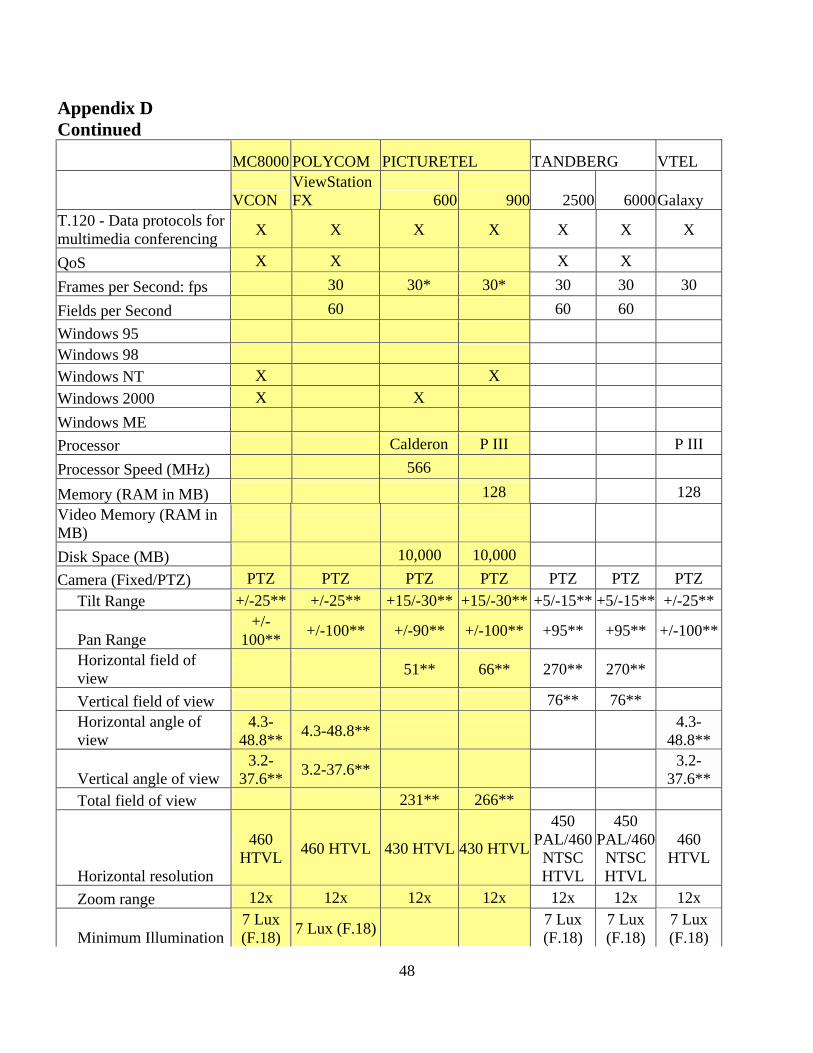
48
Appendix D Continued
MC8000 POLYCOM PICTURETEL TANDBERG VTEL
VCON ViewStation FX 600 900 2500 6000Galaxy
T.120 - Data protocols for multimedia conferencing X X X X X X X
QoS X X X X Frames per Second: fps 30 30* 30* 30 30 30 Fields per Second 60 60 60 Windows 95 Windows 98 Windows NT X X Windows 2000 X X Windows ME Processor Calderon P III P III Processor Speed (MHz) 566
Memory (RAM in MB) 128 128 Video Memory (RAM in MB)
Disk Space (MB) 10,000 10,000 Camera (Fixed/PTZ) PTZ PTZ PTZ PTZ PTZ PTZ PTZ Tilt Range +/-25** +/-25** +15/-30** +15/-30** +5/-15** +5/-15** +/-25**
Pan Range +/-
100** +/-100** +/-90** +/-100** +95** +95** +/-100**
Horizontal field of view 51** 66** 270** 270**
Vertical field of view 76** 76** Horizontal angle of view
4.3-48.8** 4.3-48.8** 4.3-
48.8**
Vertical angle of view 3.2-
37.6** 3.2-37.6** 3.2-37.6**
Total field of view 231** 266**
Horizontal resolution
460 HTVL 460 HTVL 430 HTVL 430 HTVL
450 PAL/460
NTSC HTVL
450 PAL/460
NTSC HTVL
460 HTVL
Zoom range 12x 12x 12x 12x 12x 12x 12x
Minimum Illumination 7 Lux (F.18) 7 Lux (F.18) 7 Lux
(F.18) 7 Lux (F.18)
7 Lux (F.18)

49
Appendix D Continued MC8000 POLYCOM PICTURETEL TANDBERG
VCON ViewStation FX 600 900 2500 6000Galaxy
Focus/Brightness/White Balance
Auto Auto Auto or Manual
Auto or Manual Auto
VISCA camera support X X X X X Voice activated camera positioning X X
MCU CAPABILITY X X X Local plus 3 sites 384 kbps Local plus 2 sites 512 kbps 3 sites IP plus 2 ISDN 384 kbps 1 Mbps 4 sites IP plus 1 ISDN 256 kbps 768 kbps Multicast X
Max Lan Speed 1.5
Mbps 2 Mbps 2 Mbps
USB or Card (ISA/PCI) *30 fps at 256 kbps and above ** Units in degrees

50
APPENDIX E Codec Review Synopsis IP MAX
LINE SPEED ISDN MAX LINE SPEED
ATM MAX LINE SPEED
LIST PRICE
INCLUDE MONITOR
INCLUDE CART
NOTABLE FEATURE(s)
PICTURETEL 970 2 Mbps 512 Kbps,
Quad BRI NO $20,490 XGA 34” YES One button
toggle between people and PC Graphics
960 2 Mbps 512 Kbps, Quad BRI
NO $13,990 XGA 29” YES
680 768 Kbps 128 Kbps, Single BRI
NO $6,995 NO NO
550 768 Kbps 384 Kbps NO $1,295 NO NO POLYCOM Viewstation FX H.323
2 Mbps NO NO $14,999 NO NO 100 Mbps/Full Duplex, MCU capable, 4 @ 384 Kbps, 3 @ 512 Kbps
Viewstation FX V.35
2 Mbps 1.472 Mbps NO $16,998 NO NO 100 Mbps/Full Duplex, MCU capable, 4 @ 384 Kbps, 3 @ 512 Kbps
Viewstation FX PRI
2 Mbps 1.472 Mbps NO $18,998 NO NO 100 Mbps/Full Duplex, MCU capable, 4 @ 384 Kbps, 3 @ 512 Kbps
Viewstation H.323
768 Kbps 512 Kbps NO $6,999 NO NO 10 Mbps/Half Duplex
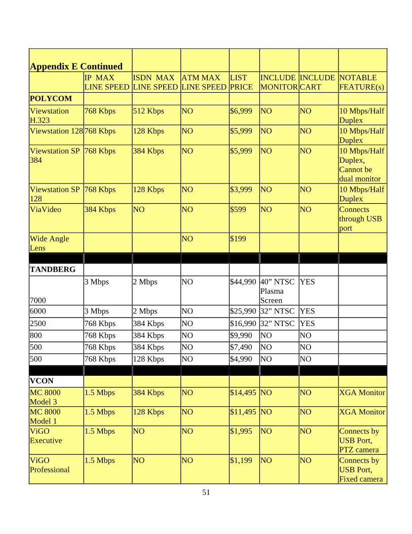
51
Appendix E Continued
IP MAX LINE SPEED
ISDN MAX LINE SPEED
ATM MAX LINE SPEED
LIST PRICE
INCLUDE MONITOR
INCLUDE CART
NOTABLE FEATURE(s)
POLYCOM Viewstation H.323
768 Kbps 512 Kbps NO $6,999 NO NO 10 Mbps/Half Duplex
Viewstation 128 768 Kbps 128 Kbps NO $5,999 NO NO 10 Mbps/Half Duplex
Viewstation SP 384
768 Kbps 384 Kbps NO $5,999 NO NO 10 Mbps/Half Duplex, Cannot be dual monitor
Viewstation SP 128
768 Kbps 128 Kbps NO $3,999 NO NO 10 Mbps/Half Duplex
ViaVideo 384 Kbps NO NO $599 NO NO Connects through USB port
Wide Angle Lens
NO $199
TANDBERG 7000
3 Mbps 2 Mbps NO $44,990 40” NTSC Plasma Screen
YES
6000 3 Mbps 2 Mbps NO $25,990 32” NTSC YES 2500 768 Kbps 384 Kbps NO $16,990 32” NTSC YES 800 768 Kbps 384 Kbps NO $9,990 NO NO 500 768 Kbps 384 Kbps NO $7,490 NO NO 500 768 Kbps 128 Kbps NO $4,990 NO NO VCON MC 8000 Model 3
1.5 Mbps 384 Kbps NO $14,495 NO NO XGA Monitor
MC 8000 Model 1
1.5 Mbps 128 Kbps NO $11,495 NO NO XGA Monitor
ViGO Executive
1.5 Mbps NO NO $1,995 NO NO Connects by USB Port, PTZ camera
ViGO Professional
1.5 Mbps NO NO $1,199 NO NO Connects by USB Port, Fixed camera

52
Appendix E Continued IP MAX
LINE SPEED ISDN MAX LINE SPEED
ATM MAX LINE SPEED
LIST PRICE
INCLUDE MONITOR
INCLUDE CART
NOTABLE FEATURE(s)
VCON ViGO Standard 384 Kbps NO NO $699 NO NO Connects by
USB Port, Fixed camera
Crusier 384 Executive
1.5 Mbps 384 Kbps NO $4,995 NO NO Hardware Card, PTZ camera
Crusier 384 1.5 Mbps 384 Kbps NO $2,995 NO NO Hardware Card, Fixed camera
Cruiser 150 1.5 Mbps 128 Kbps NO $1,295 NO NO Hardware Card, Fixed camera, Handset required
Escort 150 1.5 Mbps NO NO $899 NO NO Hardware Card, Fixed camera, Handset required
VTEL Galaxy LAN 768 Kbps 384 Kbps $14,995 NO NO Galaxy MT 768 Kbps 384 Kbps $9,995 NO NO
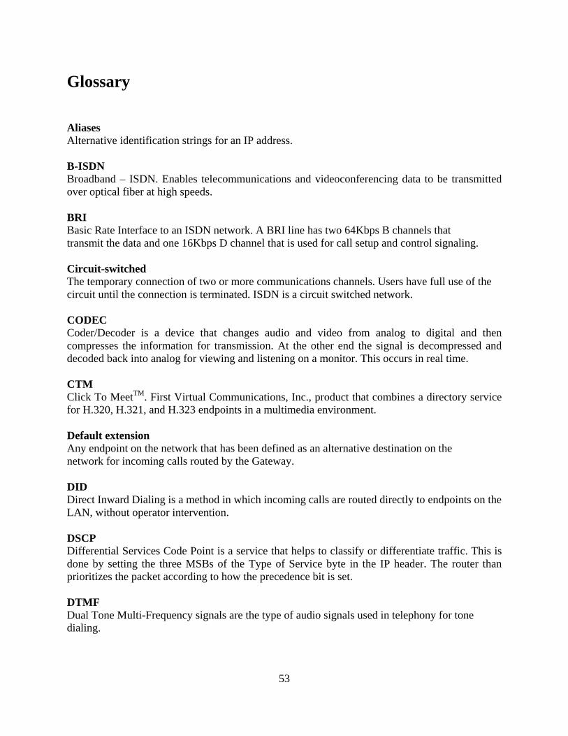
53
Glossary Aliases Alternative identification strings for an IP address. B-ISDN Broadband – ISDN. Enables telecommunications and videoconferencing data to be transmitted over optical fiber at high speeds. BRI Basic Rate Interface to an ISDN network. A BRI line has two 64Kbps B channels that transmit the data and one 16Kbps D channel that is used for call setup and control signaling. Circuit-switched The temporary connection of two or more communications channels. Users have full use of the circuit until the connection is terminated. ISDN is a circuit switched network. CODEC Coder/Decoder is a device that changes audio and video from analog to digital and then compresses the information for transmission. At the other end the signal is decompressed and decoded back into analog for viewing and listening on a monitor. This occurs in real time. CTM Click To MeetTM. First Virtual Communications, Inc., product that combines a directory service for H.320, H.321, and H.323 endpoints in a multimedia environment. Default extension Any endpoint on the network that has been defined as an alternative destination on the network for incoming calls routed by the Gateway. DID Direct Inward Dialing is a method in which incoming calls are routed directly to endpoints on the LAN, without operator intervention. DSCP Differential Services Code Point is a service that helps to classify or differentiate traffic. This is done by setting the three MSBs of the Type of Service byte in the IP header. The router than prioritizes the packet according to how the precedence bit is set. DTMF Dual Tone Multi-Frequency signals are the type of audio signals used in telephony for tone dialing.

54
E.164 An International Technology Union recommendation for telephone numbering. In short, a telephone numbering scheme allowing up to 15 digits in the number scheme. Endpoint An H.323 terminal, gateway, or Multipoint Controller Unit (MCU). An endpoint can call or be called and it can generate or end information streams. FLRQ Forwarded Location Request. A location request that is passed from router to router until a gatekeeper is found at a specified IP address. Gatekeeper The gatekeeper is an H.323 entity that provides address resolution, access control, and other services to endpoints on an H.323 network. Gateway The gateway is a device that allows H.320 switched endpoint devices to be converted to digital H.323 endpoint devices for cross communication between protocols. H.320 The ITU standard for videoconferencing over digital networks such as ISDN. H.321 The ITU standard for adaptation of H.320 videoconferencing over digital networks such as B-ISDN. H.323 The ITU standard for videoconferencing over packet switched networks such as LANs and the Internet. IP address The unique address of a computer attached to a TCP/IP network. IP addresses are 32 bits long where each octet is represented in decimal and is separated by dots. IP network A network that uses the TCP/IP protocol. ISDN Integrated Services Digital Network. ISDN is an entirely digital telephone network that allows both data and voice communication over the same line. ISDN replaces the old analog local loop and operates at significantly faster speeds than the traditional telephone service.

55
IVR Interactive Voice Response is a two-stage incoming call routing method supported by the Gateway. It enables Direct Inward Dialing to a LAN terminal even when the ISDN lines do not have multiple numbers allowing direct dialing to an endpoint. LAN Local Area Network. A network of connected computers covering a small geographic area such as a building or a campus. LDAP Lightweight Directory Access Protocol. A directory service that has many front-end applications for ease of use to find information on people. This service is not designed for multimedia applications. LRQ A signal sent out by an endpoint to a gatekeeper at a specified IP address. MCU Multipoint Controller Unit. H.323 endpoints that allow multipoint conferences to take place on the LAN. NANP North American Numbering Plan. It assigns area codes and sets rules for calls to be routed across North America. Lockheed Martin currently administers the NANP. In the context of this paper, NANP refers to a unique E.164 number accessible from the Public Switched Telephone Network (PSTN) using Direct Inward Dialing (DID). Packet-switched Networks that break up a message into smaller packets before switching the packets to their required destination. Each packet contains a destination address so all packets in a single message do not have to travel by the same path. The destination computer reassembles the packets back into their proper sequence. PBX Private Branch Exchange. A private telephone switching system in an organization that interconnects telephone extensions to each other and to the public telephone network. PRI Primary Rate Interface to an ISDN network. In the U.S., a PRI line provides 23B channels and one 64Kbps D channel (23B+D), which is equivalent to a T1 line and in Europe, a PRI line provides 30B channels and 1D channel (30B+D), equivalent to an E1 line. PSTN Public Switched Telephone Network. The worldwide telephone network.

56
RAS Registration Admission Status protocol. The communication protocol used to convey registration, admission, and status messages between H.323 endpoints and the gatekeeper. RED Random Early Detection is a service that tells the router to slow down transmission of packets until all of the packets have reached their destination. During this process, some packets may be dropped. The router resumes speed of transmission after it senses job has reached its destination. Room system H.320 based legacy videoconferencing stations. They are called room systems because they are usually large monitors with a wide-angle camera and served groups of people who meet in a room and conference with other similar groups at remote locations. RSVP Resource Reservation Protocol (RSVP) has been described by some to be the Nirvana to IP routing. At this time, RSVP is being actively developed but is not ready for deployment on core networks. Telephony The science of transmitting voice and/or video over a greater distance than you could do by shouting. T.120 ITU standard for the transmission of data sharing applications during a videoconferencing session. TCS4 A Direct Inward Dialing routing method for H.320 calls supported by a gateway. This method requires support by the H.320 device performing the dialing. Transcoding The ability of a device to convert between one protocol and another. All aspects ranging from audio and video to control signaling are converted. V.35 The V.35 is a serial interface used to connect Data Terminal Equipment and Data Circuit Terminating Equipment (DTE/DCE). VoIP Voice over IP is the ability to make telephone calls over IP based data networks with suitable quality of service. WAN Wide Area Network. A communications network over a wide geographic area.
57
WRED Weighted Random Early Detection is Cisco Systems version of Random Early Detection. It is used to prioritize traffic while telling the router to slow down the transmission of packets until all of the packets have reached their destination. Zone In H.323 networks, a collection of terminals, gateways, and MCUs managed by a single gatekeeper. A zone must include at least one terminal and may include several LAN segments connected by routers.