
Viability of MQL in Turning Operation Of AS 1443 2004 M ... Viability Of MQL In Turning Operation...
12
IOSR Journal of Mechanical and Civil Engineering (IOSR-JMCE) e-ISSN: 2278-1684,p-ISSN: 2320-334X, Volume 13, Issue 2 Ver. II (Mar. - Apr. 2016), PP 14-25 www.iosrjournals.org DOI: 10.9790/1684-1302021425 www.iosrjournals.org 14 | Page “Viability of MQL in Turning Operation Of AS 1443 – 2004 M 1020MS Bright With Respect To Cutting Temperature, Surface Roughness and Cost of Lubrication” Syed Mohsin Ashfaquddin [1] , Prof. Rahul. D Shelke [2] 1 (Mechanical Department, Dr. BAMU, India) 2 (Mechanical Department, Everest College, Dr. BAMU, India) Abstract: Lubrication is the process or technique used to reduce friction between surfaces coming in contact and relative to each other, by interposing a substance called a lubricant between them. Metalworking fluids (MWF) are known to provide many benefits to ensure that metal parts can be machined in a cost-effective manner. The positive features of metalworking fluids have long been established and include friction reduction, cooling, corrosion protection, welding protection from the tool to the workpiece and the washing away of metal chips. In the continuous quest for reducing the use of coolants in machining, only one process can offer a near- term solution for practical applications. This process uses a minimum quantity of lubrication and is referred to as “MQL”. In MQL, an air–oil mixture called an aerosol is fed into the machining zone. Compared to dry machining, Aerosols are generated using a process called atomization, which is the conversion of bulk liquid into a spray or mist (i.e., collection of tiny droplets), often by passing the liquid through a nozzle. MQL has the advantages of being inexpensive and simple retrofitting of the existing machines, same cutting tools used for flood MWF will work, easy to use and maintain equipment etc. However, these advantages do come at a cost. The most prohibitive part of switching to dry machining is the large capital expenditure required to start a dry machining operation. This paper aims at doing a systematic study and review of the available information about minimum quantity lubrication to evaluate its present status in the research and thereby draw some conclusion about its feasibility of application in the practical world. Keywords: Aerosol, lubrication, Metal working fluids, MQL moving I. Introduction 1.1 History of Machining Machining is a process in which a piece of raw material is cut into a desired final shape and size by a controlled material-removal process. Machining is a part of the manufacture of many metal products, but it can also be used on materials such as wood, plastic, ceramic, and composites. A person who specializes in machining is called a machinist. A room, building, or company where machining is done is called a machine shop or shop floor. Machining can be a business, a hobby, or both. The precise meaning of the term machining has evolved over the past one and a half centuries as technology has advanced. In the 18th century, the word machinist simply meant a person who built or repaired machines. 1.2 Cost involved in Machining Manufacturing cost is the sum of costs of all resources consumed in the process of making a product. The manufacturing cost is classified into three categories: direct materials cost, direct labor cost and manufacturing overhead. Direct materials cost: Direct materials are the raw materials that become a part of the finished product. Manufacturing adds value to raw materials by applying a chain of operations to maintain a deliverable product. There are many operations that can be applied to raw materials such as welding, cutting and painting. Direct labor cost: The direct labor cost is the cost of workers who can be easily identified with the unit of production. Types of labor who are considered to be part of the direct labor cost are the assembly workers on an assembly line. Manufacturing overhead: Manufacturing overhead is any manufacturing cost that is neither direct materials cost nor direct labor cost. Manufacturing overhead includes all charges that provide support to manufacturing.
Transcript of Viability of MQL in Turning Operation Of AS 1443 2004 M ... Viability Of MQL In Turning Operation...
IOSR Journal of Mechanical and Civil Engineering (IOSR-JMCE)
e-ISSN: 2278-1684,p-ISSN: 2320-334X, Volume 13, Issue 2 Ver. II (Mar. - Apr. 2016), PP 14-25
www.iosrjournals.org
DOI: 10.9790/1684-1302021425 www.iosrjournals.org 14 | Page
“Viability of MQL in Turning Operation Of AS 1443 – 2004 M
1020MS Bright With Respect To Cutting Temperature,
Surface Roughness and Cost of Lubrication”
Syed Mohsin Ashfaquddin [1]
, Prof. Rahul. D Shelke[2]
1(Mechanical Department, Dr. BAMU, India)
2(Mechanical Department, Everest College, Dr. BAMU, India)
Abstract: Lubrication is the process or technique used to reduce friction between surfaces coming in contact
and relative to each other, by interposing a substance called a lubricant between them. Metalworking fluids
(MWF) are known to provide many benefits to ensure that metal parts can be machined in a cost-effective
manner. The positive features of metalworking fluids have long been established and include friction reduction,
cooling, corrosion protection, welding protection from the tool to the workpiece and the washing away of metal
chips. In the continuous quest for reducing the use of coolants in machining, only one process can offer a near-
term solution for practical applications. This process uses a minimum quantity of lubrication and is referred to
as “MQL”. In MQL, an air–oil mixture called an aerosol is fed into the machining zone. Compared to dry
machining, Aerosols are generated using a process called atomization, which is the conversion of bulk liquid
into a spray or mist (i.e., collection of tiny droplets), often by passing the liquid through a nozzle. MQL has the
advantages of being inexpensive and simple retrofitting of the existing machines, same cutting tools used for
flood MWF will work, easy to use and maintain equipment etc. However, these advantages do come at a cost.
The most prohibitive part of switching to dry machining is the large capital expenditure required to start a dry
machining operation. This paper aims at doing a systematic study and review of the available information about
minimum quantity lubrication to evaluate its present status in the research and thereby draw some conclusion
about its feasibility of application in the practical world.
Keywords: Aerosol, lubrication, Metal working fluids, MQL moving
I. Introduction 1.1 History of Machining
Machining is a process in which a piece of raw material is cut into a desired final shape and size by a controlled
material-removal process. Machining is a part of the manufacture of many metal products, but it can also be
used on materials such as wood, plastic, ceramic, and composites. A person who specializes in machining is
called a machinist. A room, building, or company where machining is done is called a machine shop or shop
floor. Machining can be a business, a hobby, or both. The precise meaning of the term machining has evolved
over the past one and a half centuries as technology has advanced. In the 18th century, the
word machinist simply meant a person who built or repaired machines.
1.2 Cost involved in Machining
Manufacturing cost is the sum of costs of all resources consumed in the process of making a product. The
manufacturing cost is classified into three categories: direct materials cost, direct labor cost and manufacturing
overhead.
Direct materials cost: Direct materials are the raw materials that become a part of the finished product.
Manufacturing adds value to raw materials by applying a chain of operations to maintain a deliverable product.
There are many operations that can be applied to raw materials such as welding, cutting and painting.
Direct labor cost: The direct labor cost is the cost of workers who can be easily identified with the unit of
production. Types of labor who are considered to be part of the direct labor cost are the assembly workers on
an assembly line.
Manufacturing overhead: Manufacturing overhead is any manufacturing cost that is neither direct materials
cost nor direct labor cost. Manufacturing overhead includes all charges that provide support to manufacturing.

“Viability Of MQL In Turning Operation Ofas 1443 – 2004 M 1020MS Bright With Respect To..
DOI: 10.9790/1684-1302021425 www.iosrjournals.org 15 | Page
Cost of Lubrication: Lubrication is the process or technique used to reduce friction between surfaces coming
in contact and moving relative to each other, by interposing a substance called a lubricant between them. The
lubricant can be a solid, or liquid such as oil, a liquid-liquid dispersion (a grease) or a gas.
The science of friction, lubrication and wear is called tribology. Adequate lubrication allows smooth
continuous operation of equipment, reduces the rate of wear, and prevents excessive stresses or seizures
at bearings. When lubrication breaks down, components can rub destructively against each other, causing heat,
local welding, destructive damage and failure.
1.3 Machining with MQL Present Scenario
To understand why MQL machining works, a great body of the reported results on MQL has to be
classified in a systemic fashion and analyzed using the fundamentals of metal cutting tribology. The lack of
information on the experimental conditions, including the parameters of the aerosol, prevents any reasonable
systematization of the work done. Unfortunately, many of these important parameters are not reported in many
research documents and papers on MQL. As a result, a process or manufacturing engineer who wants to
implement MQL is not equipped with sufficient recommendations to make proper choices of the equipment,
parameters and regimes of MQL for a particular machining operation.
1.3.1 Introduction of Minimum Quantity Lubrication
In the continuous quest for reducing the use of coolants in machining, only one process can offer a
near-term solution for practical applications. This process uses a minimum quantity of lubrication and is referred
to as “MQL”. In MQL, an air–oil mixture called an aerosol is fed into the machining zone. Compared to dry
machining, MQL substantially enhances cutting performance in terms of increasing tool life and improving the
quality of the machined parts. Small oil droplets carried by the air fly directly to the tool working zone,
providing the needed cooling and lubricating actions. Aerosols are generated using a process called atomization,
which is the conversion of bulk liquid into a spray or mist (i.e., collection of tiny droplets), often by passing the
liquid through a nozzle. An atomizer is an atomization apparatus; carburetors, airbrushes, misters, and spray
bottles are only a few examples of the atomizers used ubiquitously. In internal combustion engines, fine-grained
fuel atomization is instrumental to efficient combustion. In short, MQL delivers a very small amount of coolant
to a cutter‟s edge in the form of an oil mist or aerosol, as opposed to traditional techniques of flooding the
workpiece and tool with a substantial volume of liquid coolant. Just a tiny bit of that aerosol is left on the chips,
workpiece and machine during the cutting operation.
1.3.2 Classification of Minimum Quantity Lubrication
Unfortunately, there are no accepted classifications of MQL so it is very difficult for a practical
engineer or plant manager to make the proper choice about the regimes of MQL and equipment needed.
However the following classification can ease the purpose of study.
1.3.3 Classification by Aerosol Supply
The first level of MQL classification includes a way by which aerosol is supplied into the machining
zone.
1) MQL 1: MQL with external aerosol supply. In MQL 1, the aerosol is supplied by an external nozzle
placedin the machine similar to a nozzle for flood MWF supply.
2) MQL 2: MQL with internal (through-tool) aerosol supply. In MQL 2, the aerosol is supplied through the
tool similar to the high-pressure method of internal MWFs supply.
As the name implies, MQL with an external aerosol supply (MQL 1) includes the external nozzle that
supplies the aerosol. There are two options in MQL 1, which are shown in Figure 1.
Figure 1.1 MQL with external aerosol supply
MQL 1 with an ejector nozzle: The oil and the compressed air are supplied to the ejector nozzle and the
aerosol is formed just after the nozzle, as shown in Figure1. One of the possible designs of ejector nozzle is
shown in Figure2. As can be seen, it has two air passages. The first one is external and creates the air envelope
that served as the mixing chamber. The second one provides the atomizing air supply. The oil to be atomized is
supplied through the central passage.MQL 1 with a conventional nozzle: The aerosol is prepared in an external

“Viability Of MQL In Turning Operation Ofas 1443 – 2004 M 1020MS Bright With Respect To..
DOI: 10.9790/1684-1302021425 www.iosrjournals.org 16 | Page
atomizer and then supplied to a conventional nozzle, as shown in Figure1.1. The nozzle deign is similar to that
used in flood MWF supply.
Figure 1.2 MQL with internal (through-tool) aerosol supply
Figure 1.3Nozzle design for MQL with external aerosol supply
MQL with external aerosol supply is probably the cheapest and simplest method. ThisNozzle unit
works on an air pressure of 10-16 m/sec, which should be adjusted on the compressor. Attaching the fitting to
the air supply, dropping the suction tube into an oil container, and locating the nozzle by means of the pipe
through which cutting fluid passes, one can get MQL for a cost of Rs 1800/. The soft wire (used in medical field
as inter-venous saline unit) in the nose can be bent to direct the fluid in the nozzleon to the work in the form of
spray. It is designed for easy transfer from one machine to another
.
Figure 1.4The soft wire (used in medical field as inter-venous saline unit)
However, adjustments are not that simple. If no special precautions are taken, the unit generates a
dense mist that covers everything in the shop, including the operator‟s lungs. To prevent this from happening
and to gain the full control on the parameters of aerosol, one needs to have (design or buy) a hydraulic unit
similar to that shown in Figure 1.4.
Figure 1.5: Aerosol control unit
When such a unit is used, the parameters of the aerosol can be adjusted in a wide range in terms of
droplet size and oil flow rate by setting appropriate air and oil flow rates and by adjusting the pressure in the oil
reservoir. Moreover, such a device prevents oil spills as it shuts down the oil supply line when the air supply is
not available.
MQL 1 with a conventional nozzle is probably the simplest method. An external atomizer required is an off-the-
shelf product, such as that shown in Figure 1.5.
1.4MQL 1 has the following advantages:
• Inexpensive and simple retrofitting of the existing machines
• The same cutting tools used for flood MWF will work
“Viability Of MQL In Turning Operation Ofas 1443 – 2004 M 1020MS Bright With Respect To..
DOI: 10.9790/1684-1302021425 www.iosrjournals.org 17 | Page
• Easy to use and maintain equipment
• The equipment can be moved from one machine to another
• Relative flexibility of MQL 1 with a conventional nozzle as the position of nozzle can be adjusted for the
convenience of operator. As such, the parameters of the aerosol do not depend on the particular nozzle
location.
• The equipment can be moved from one machine to another.
• Various standard and special nozzle designs are available with MQL 1 with a conventional nozzle to suite
most common metal machining operations and tool designs. It is proven to be particularly effective in
turning, face milling and sawing
1.5 MQL 1 has the following disadvantages:
• Both MQL 1; with an ejector nozzle and with a conventional nozzle do not work well with drills and
boring tools as an aerosol cannot penetrate into the hole being machined
• A critical aspect for MQL 1 with an ejector nozzle and an important aspect for MQL 1 with a conventional
nozzle is the location of the nozzle relative to the working part of the tool. For both methods, this location
must be fixed, i.e., should not change as the tool moves. Note that this issue is not that important in flood
MWF supply where gravity and the energy of MWF flow cover a much wider range of possible nozzle
locations
• The parameters of the aerosol should be adjusted for each particular metal machining operation and the
work material. This makes MQL 1 less attractive option in a job-shop environment
1.6 Need and Significance of the work
The United Auto Workers petitioned the Occupational Safety and Health Administration (OSHA) to
lower the permissible exposure limit for metalworking fluids from 5.0 mg/m3 to 0.5 mg/m3. In response, OSHA
established the Metalworking Fluid Standards Advisory Committee (MWFSAC) in 1997 to develop standards or
guidelines related to metalworking fluids. In its final report in 1999, MWFSAC recommended that the exposure
limit be 0.5 mg/m3 and that medical surveillance, exposure monitoring, system management, workplace
monitoring and employee training are necessary to monitor worker exposure to metalworking fluids. In the
current, competitive manufacturing environment, end-users of metalworking fluids are looking to reduce costs
and improve productivity. The costs of maintaining and eventually disposing of metalworking fluids, combined
with the aforementioned health and safety concerns, have led to a heightened interest in either eliminating
metalworking fluid altogether or limiting the amount of metalworking fluid applied. The certain risks that are
involved with the use of coolants may be enumerated as follows
1) Generation of dioxin
2) Harm to the human body
3) Wear of machine tool
4) Increase of maintenance cost
5) Danger of fire
Minimum quantity lubrication which is a very new method delivers the required minimum quantity of
lubricant mixed with air and performs machining through a continuous supply of this air/oil mixture to the tool
tip. It makes it possible to reduce the amount of coolant being used to nearly zero thereby resulting in
minimizing most of the above mentioned risks involved with the use of coolants. Hence there seems to be a
necessity to explore this method of machining.
1.7 Objectives of the study
The objectives of this study can be briefly stated as under
This study of general aspects of minimum quantity lubrication is undertaken to try and understand the
underlying possibilities of this relatively new concept
This report will also aim at studying and understanding the effects of minimum quantity lubrication on
some of the machining parameters such as surface finish and temperature.
II. Literature Review 2.1 Introduction
To understand why Minimum quantity lubrication machining works, a great body of the reported
results on MQL has to be classified in a systemic fashion and analyzed using the fundamentals of metal cutting
process. The lack of information on the experimental conditions, including the parameters of the aerosol,
prevents any reasonable systematization of the work done. Unfortunately, many of these important parameters
are not reported in many research documents and papers on MQL. As a result, a process or manufacturing
“Viability Of MQL In Turning Operation Ofas 1443 – 2004 M 1020MS Bright With Respect To..
DOI: 10.9790/1684-1302021425 www.iosrjournals.org 18 | Page
engineer who wants to implement MQL is not equipped with sufficient recommendations to make proper
choices of the equipment, parameters and regimes of MQL for a particular machining operation. Although
professional magazines have published a number of articles on MQL, these articles do not present complete and
systematic information on MQL even at the application level, limiting their scope to rather promotional aspects.
2.2 Some Studies on MQL
Hosokawa, Nozaki R, and A Ueda T, [1] found that temperature reduction in oil-mist turning is approximately
5%, while in oil-mist end milling it is 10–15% and in oil-mist drilling it is 20–25% compared to the temperature
in dry cutting.
Chien and Wu [2] evaluated Minimum Quantity lubrication of three different steel materials. They found that
the machining performance is affected by the lubrication type and its flow rate, the nozzle design, the distance
between nozzle and tool tip, and the workpiece material. All these parameters are found to be dependent on the
work material and process conditions. They concluded that only when the appropriate oil quantity and
appropriate distance between the nozzle and tool tip are selected properly does MQL provides the optimum
process condition.
Nikhil Ranjan Dhar, Islam S and Kamruzzaman M [3]studied the effect of Near Dry Machining in tuning of
4340 steel using external nozzle and aerosol supply to the tool. Interestingly, the authors found that the tool life
is the same for dry and wet machining, which is in direct contradiction with common shop practice. They also
found that the temperature at the tool–chip interface reduced by 5–10% (depending upon the particular
combination of the cutting speed and feed) in NDM compared to wet machining. As a result, tool life and finish
of the machined surface improved by 15–20%.
Nakamura T, Itoigawa F, Yoshimura H and Niwa K[4] found that, in machining of aluminium, the cutting
force is lower and the surface finish is better with OoW NDM compared with dry, traditional NDM and wet
machining.
Stephenson DA and Filipovic A [5] did not find any difference in tool life in gun-drilling and cross-hole
drilling of crankshafts between wet machining and MQL. They are of the opinion that the difference between
machining parameters of flooded lubrication and Minimum Quantity of Lubrication is negligible.
Shinozuka J, Kamata Y and Obikawa T [6] evaluated the performance of Near Dry Machining in high-speed
grooving of a 0.45%C carbon steel with a carbide tool coated with TiC/TiCN/TiN triple coating layers. Studying
tool life in grooving, they found that a vegetable oil supplied at constant rate of 7 ml/h reduced the corner and
flank wears more effectively than water-soluble oil at high cutting speeds of 4 and 5 m/s.
Khan MMA and Dhar NR [7] found that NDM with vegetable oil reduced the cutting forces by about 5–15%.
The axial force decreased more predominantly than the power force. They attributed this reduction as well as the
improved tool life and finish of the machined surface to reduction of the cutting zone temperature as the major
reason for the improved performance of machining operations.
Kuan-Ming Li K-M, Liang SY [8] found the cutting forces in machining 1045 steel to be lower in NDM
compared with dry cutting. They also attributed this reduction to the cutting temperature difference.
III. System Development
3.1 Cutting Temperature in Machining with Minimum Quantity Lubrication:
The research on cutting temperature in metal cutting began as early as 1906. It was found that the
cutting temperature was important to tool life. An empirical equation to estimate the tool life in terms of the
cutting speed (consequently the tool temperature) was developed and subsequently widely used. Since that time,
the steady state cutting temperature for dry machining has been studied by many researchers. Among them,
Kuan Ming Lisummarized and modified the work of previous researches to estimate the temperature distribution
for the tool in metal cutting.
The cutting temperature at the tool tip can be calculated according to the heat distribution on the tool-
chip interface. The temperature change in the workpiece is caused by the primary heat source, the rubbing heat
source, and heat the loss due to cooling. The proposed model is verified by experimental data of turning medium
carbon steel AS 1443 – 2004 M 1020(MS BRIGHT) under minimum quantity lubrication. The temperatures are
measured by an embedded thermocouple underneath the tool insert for comparison with model predictions.

“Viability Of MQL In Turning Operation Ofas 1443 – 2004 M 1020MS Bright With Respect To..
DOI: 10.9790/1684-1302021425 www.iosrjournals.org 19 | Page
3.2Temperature for Sharp Tools under Near Dry Condition:
The temperature distribution on the tool-chip interface for sharp tool edges in dry machining can be
calculated with an analytical model, as proposed by Kuan Ming Li and Steven Liang [8]. It is believed that the
temperature rise in dry machining is caused by the primary heat source at the shear plane and the secondary heat
source at the tool-chip interface. In near dry machining, three heat sources/losses are considered: the primary
heat source due to shear deformation, the secondary heat source due to friction, and the heat loss due to air-oil
mixture cooling. The following sections describe how the heat loss due to convection on the tool flank face and
workpiece is calculated based on a stationary heat source model (for the tool) and a moving-band heat source
model (for the workpiece). The temperature distribution on the tool-chip interface is then estimated by the
superposition of temperature changes due to different heat sources and heat losses.
Figure 3.1: Heat sources and heat losses for the 2D model in near dry turning
3.2.1.1 Temperature Rise on the Tool Chip Interface in Chip
Temperature rise in the chip is attributed to both the primary heat source and the secondary heat source.
The effect of the primary heat source is considered as this heat source moving in a continuous chip flow. The
back side of the chip is assumed to be adiabatic. Then, the primary heat source and the imaginary heat source
are symmetric with respect to the back side of the chip. The schematic of the imaginary chip and the heat
sources is shown in Figure 3.3. The temperature rise due to the primary heat source is expressed as
The above equation is valid only in the region of the chip physically removed, not the imaginary chip
as depicted by the dash lines since there is not any material in the imaginary region.
Again, the above equation is valid only in the region of the chip removed. Considering both the primary heat
source and the secondary heat source, the temperature rise in the chip is
The heat loss intensity is calculated according to forced convection model as
Since the flow of the applied air-oil mixture is parallel to the tool flank face and the machined
workpiece, the forced convection effect can be considered as a fluid flow passing through parallel flat surfaces.
The average heat transfer coefficient in the above equation can be estimated by the Nusselt number as following
3.2.1.3 Temperature Distribution on the Tool-Chip Interface
The temperature rise on the tool-chip interface is considered the same as that in the chip and in the tool.
The heat partition function is solved by the following relationship.
If a total of n points are of interest on the tool-chip interface, the same number of equations can be solved for the
heat partition factors. Subsequently, the temperature distribution on the tool-chip interface can be obtained.

“Viability Of MQL In Turning Operation Ofas 1443 – 2004 M 1020MS Bright With Respect To..
DOI: 10.9790/1684-1302021425 www.iosrjournals.org 20 | Page
3.2.2.3 Temperature Rise in the Workpiece
The temperature rise in the workpiece is caused by the primary heat source, the rubbing heat source,
and the heat loss. The heat sources and the heat loss are considered as moving heat bands with respect to any
fixed point in the workpiece. The temperature rise in workpiece was estimated by the moving heat bands models
with proper coordinate systems. The imaginary part of the primary heat source is plotted in Figure 3.7. The heat
source is assumed to move in a semi-infinite material with imaginary material. The effect of the primary heat
source is expressed as
3.3 Surface Finish in machining with Minimum Quantity Lubrication
Since machining is often the manufacturing process that determines the final geometry and dimensions
of the part, it‟s also determines the part‟s surface texture. Surface roughness of a machined surface depends on:
(a) geometrical factors, (b) work material factors, and (c) vibrations and machine tool factors. The two most
important factors affecting the surface finish are tool geometry (nose radius) and the feed (Figure 5.1). The
effect of nose radius and feed can be combined in an equation to predict the ideal average roughness for a
surface produced by a single-point tool. The equation applies to operations like turning, shaping, and planning:
𝐑𝐢 =𝐟²
𝟑𝟐 × 𝐑
Where Ri is theoretical arithmetic average surface roughness (in or mm), f is feed (in or mm), and R is nose
radius on the tool point (in or mm).
Ideal surface roughness (Ri) represents the best possible surface finish that can be obtained with a
given tool shape and feed, and can only be approached if built-up edge (BUE) formation, chatter, inaccuracies in
the machine tool movement, etc., are eliminated. Quantitatively, it is useful to express the roughness in terms of
a single parameter, i.e. the arithmetical mean value.
In most machining operations, ideal surface finish can not be achieved because of factors related to the
work material and it‟s interaction with the tool. An empirical ratio (Rai ) can be developed to covert the ideal
roughness value into an estimate of the actual surface roughness. This ratio takes into account BUE, tearing, and
other factors. Actual surface roughness can be predicted by the following equation:
𝐑𝐚 = 𝐑𝐚𝐢 𝐱 𝐑𝐢
Where Ra is the estimated value of actual roughness; Rai is the ratio of actual to ideal surface finish; and Ri
ideal roughness value calculated.
Surface roughness plays an important role in determining how a real object will interact with its
environment. Rough surfaces usually wear more quickly and have higher friction coefficients than smooth
surfaces. Roughness is often a good predictor of the performance of a mechanical component, since
irregularities in the surface may form nucleation sites for cracks or corrosion.
3.4 Cost analysis of Machining with respect to Lubrication
The historical, widespread use of coolants as MWF‟s has overshadowed MQL and kept it as a marginal
technology. Sadly, not many machinists know or truly understand the concepts behind MQL and therefore never
get to enjoy its many benefits. In an industry where production efficiency is crucial, the unknowns of a „new‟
technology pose the potential threat of complications and downtime. The fear of the unknown may be the
greatest challenge to MQL, and the fact that a large percentage of metalworking equipment comes already
equipped with flood coolant systems is surely no help either.
𝐋𝐜 = 𝐐𝐥 × 𝐂𝐨𝐬𝐭 𝐨𝐟 𝐋𝐮𝐛𝐫𝐢𝐜𝐚𝐧𝐭/𝐋𝐢𝐭𝐫𝐞
Where Lc is lubrication cost and Ql is quantity of lubricant.
Repeated exposure to many coolants can have real consequences for the humans involved as well.
Some coolants have been shown to cause dermatitis and to be carcinogenic with long-term exposure to coolant
vapor. Studies have shown that the cumulative cost of coolants/MWFs can equal as high as 15% of the total
cost to produce a part.

“Viability Of MQL In Turning Operation Ofas 1443 – 2004 M 1020MS Bright With Respect To..
DOI: 10.9790/1684-1302021425 www.iosrjournals.org 21 | Page
IV. Performance Analysis
4.1 Verification of Analytical Output by Experimental Method
In the tests that were conducted, the validation of cutting temperatures in MQL was verified by
measuring the temperatures with an embedded thermocouple located under the tool when cutting AS 1443 –
2004 M 1020(MS BRIGHT) with uncoated carbide tool inserts on a lathe under various cutting conditions. The
cutting conditions are selected in the ranges of cutting speed = 45.75-137.25 m/min, feed = 0.0508-0.1016
mm/rev and depth of cut = 0.508-1.016 mm. The workpiece is 31.75 mm in diameter and 76.2 mm long. The air
fluid mixture is supplied at 12.5ml/hr at a pressure of 275.8 kPa. The conditions that were observed during the
tests can drafted into tabular form as follows
.
4.1.1 Design of Experiment
Design of Experiments (DOE) is a method to identify the important factors in a process. In engineering
settings, there are usually multiple factors involved and it is typically important to consider them together in
case they interact (influence each other). This is done using a full factorial DOE. Here, a three level factorial
DOE was used. This means three levels of each factor will be studied at once. If there are kfactors that we need
to evaluate in a process we need to run the experiment 3ktimes. Each factor will have three levels.
The three-level design is written as a 3kfactorial design. It means that k factors are considered, each at 3 levels.
These are (usually) referred to as low, intermediate and high levels. These levels are numerically expressed as 0,
1, and 2. One could have considered the digits -1, 0, and +1, but this may be confusing with respect to the 2-
level designs since 0 is reserved for center points. Therefore, we will use the 0, 1, 2 scheme. The reason that the
three-level designs were proposed is to model possible curvature in the response function and to handle the case
of nominal factors at 3 levels. A third level for a continuous factor facilitates investigation of a quadratic
relationship between the response and each of the factors.
These treatments may be displayed as follows
The design can be represented pictorially by
Figure 4.1A 3
3 Design Schematic
For the present experimental conditions three factors that were considered are cutting speed, feed and
depth of cut. And for each of these factors three levels were taken into consideration. Based on the full factorial
theory for three factors and three levels we can say that 33 =27 number of tests are to be conducted. These are
drafted in tabular form as follows.
Table 4.2: Test cutting conditions & readings temperature, values for surface roughness and cost of lubricant.
Temperature (0C)
Test
No
Speed
(m/min)
Feed (mm/rev) Depth of cut
(mm)
Flooded MQL
Analytical Experimental Analytical Experime
ntal
1 45.75 0.0508 0.508 270 250 235 270
2 45.75 0.0762 0.508 430 443 374 430
3 45.75 0.1016 0.508 394 405 343 394
4 45.75 0.0508 1.016 267 248 238 267
5 45.75 0.0762 1.016 420 440 374 420
6 45.75 0.1016 1.016 396 400 352 396
7 45.75 0.0508 0.762 265 255 236 265
8 45.75 0.0762 0.762 425 439 378 425
9 45.75 0.1016 0.762 400 410 356 400
10 91.5 0.0508 0.508 585 598 521 585
11 91.5 0.0762 0.508 600 550 534 600
12 91.5 0.1016 0.508 580 570 516 580
13 91.5 0.0508 1.016 590 600 525 590
14 91.5 0.0762 1.016 575 500 512 575
15 91.5 0.1016 1.016 575 565 512 575
16 91.5 0.0508 0.762 570 590 519 570
17 91.5 0.0762 0.762 610 520 555 610
“Viability Of MQL In Turning Operation Ofas 1443 – 2004 M 1020MS Bright With Respect To..
DOI: 10.9790/1684-1302021425 www.iosrjournals.org 22 | Page
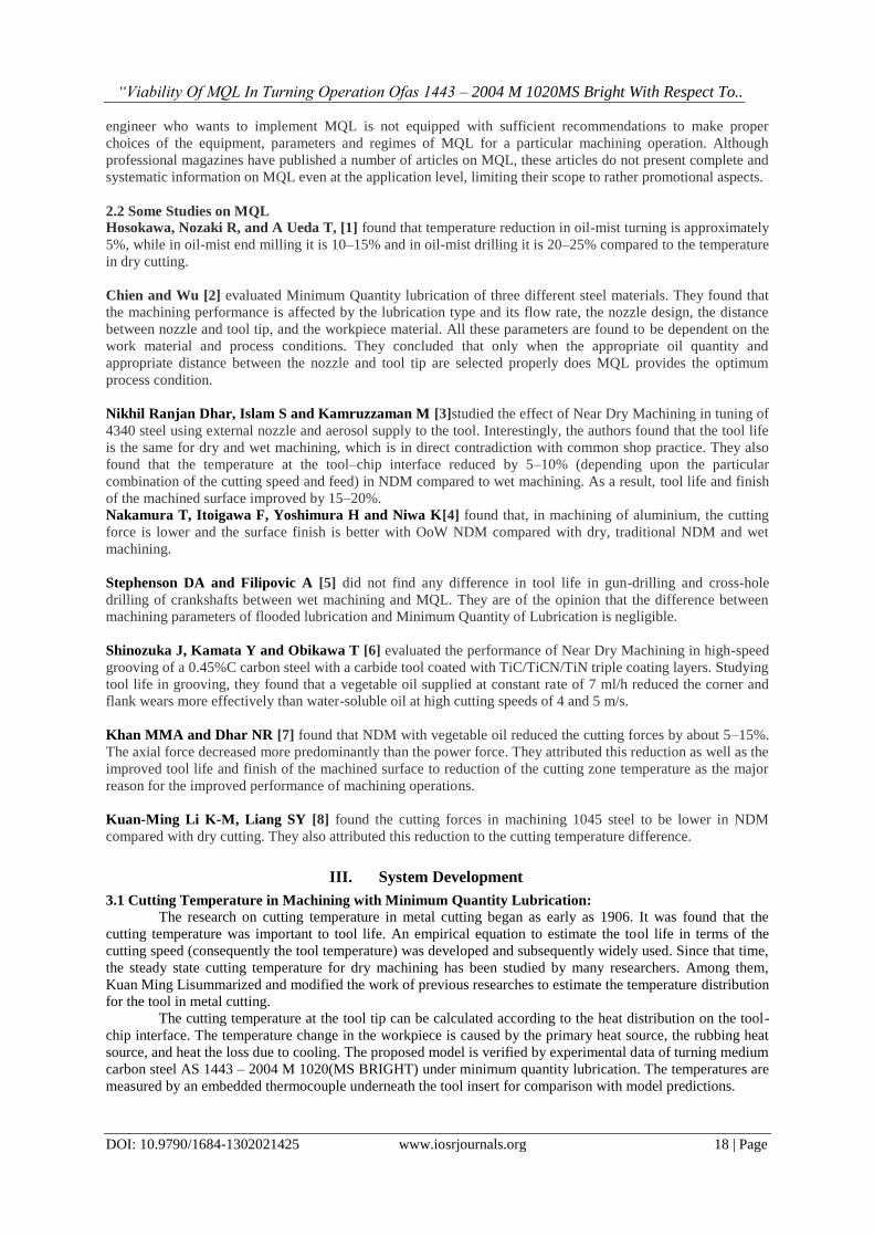
Table 4.2: Test cutting conditions & values for surface roughness and cost of lubricant.
The estimated parameters according to the measured cutting forces for sharp tool and for worn tools are
listed in Table 4.2. When investigating the near dry lubrication effect on the cutting temperatures, the values of
rubbing force on the tool-workpiece interface Fcw is used.
The model-predicted temperatures and the measured temperatures under the tool insert for different cutting
conditions and the values for surface roughness are shown in table 4.2.
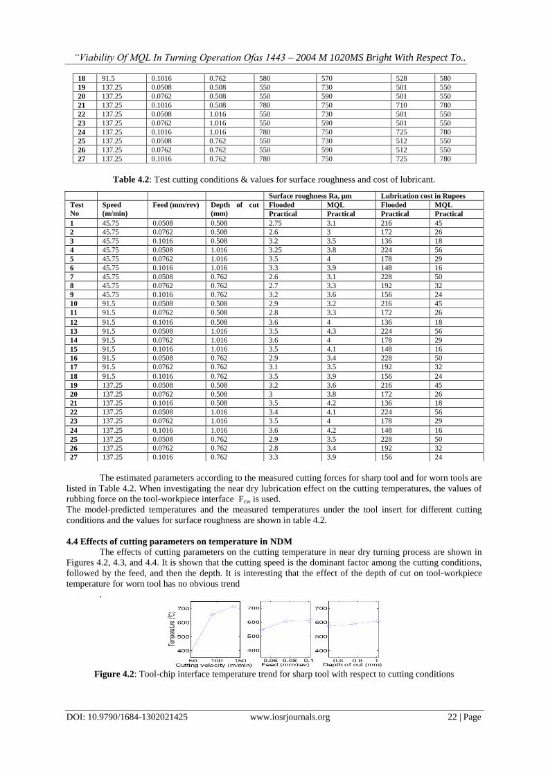
4.4 Effects of cutting parameters on temperature in NDM
The effects of cutting parameters on the cutting temperature in near dry turning process are shown in
Figures 4.2, 4.3, and 4.4. It is shown that the cutting speed is the dominant factor among the cutting conditions,
followed by the feed, and then the depth. It is interesting that the effect of the depth of cut on tool-workpiece
temperature for worn tool has no obvious trend
.
Figure 4.2: Tool-chip interface temperature trend for sharp tool with respect to cutting conditions
18 91.5 0.1016 0.762 580 570 528 580
19 137.25 0.0508 0.508 550 730 501 550
20 137.25 0.0762 0.508 550 590 501 550
21 137.25 0.1016 0.508 780 750 710 780
22 137.25 0.0508 1.016 550 730 501 550
23 137.25 0.0762 1.016 550 590 501 550
24 137.25 0.1016 1.016 780 750 725 780
25 137.25 0.0508 0.762 550 730 512 550
26 137.25 0.0762 0.762 550 590 512 550
27 137.25 0.1016 0.762 780 750 725 780
Surface roughness Ra, µm Lubrication cost in Rupees
Test
No
Speed
(m/min)
Feed (mm/rev) Depth of cut
(mm)
Flooded MQL Flooded MQL
Practical Practical Practical Practical
1 45.75 0.0508 0.508 2.75 3.1 216 45
2 45.75 0.0762 0.508 2.6 3 172 26
3 45.75 0.1016 0.508 3.2 3.5 136 18
4 45.75 0.0508 1.016 3.25 3.8 224 56
5 45.75 0.0762 1.016 3.5 4 178 29
6 45.75 0.1016 1.016 3.3 3.9 148 16
7 45.75 0.0508 0.762 2.6 3.1 228 50
8 45.75 0.0762 0.762 2.7 3.3 192 32
9 45.75 0.1016 0.762 3.2 3.6 156 24
10 91.5 0.0508 0.508 2.9 3.2 216 45
11 91.5 0.0762 0.508 2.8 3.3 172 26
12 91.5 0.1016 0.508 3.6 4 136 18
13 91.5 0.0508 1.016 3.5 4.3 224 56
14 91.5 0.0762 1.016 3.6 4 178 29
15 91.5 0.1016 1.016 3.5 4.1 148 16
16 91.5 0.0508 0.762 2.9 3.4 228 50
17 91.5 0.0762 0.762 3.1 3.5 192 32
18 91.5 0.1016 0.762 3.5 3.9 156 24
19 137.25 0.0508 0.508 3.2 3.6 216 45
20 137.25 0.0762 0.508 3 3.8 172 26
21 137.25 0.1016 0.508 3.5 4.2 136 18
22 137.25 0.0508 1.016 3.4 4.1 224 56
23 137.25 0.0762 1.016 3.5 4 178 29
24 137.25 0.1016 1.016 3.6 4.2 148 16
25 137.25 0.0508 0.762 2.9 3.5 228 50
26 137.25 0.0762 0.762 2.8 3.4 192 32
27 137.25 0.1016 0.762 3.3 3.9 156 24

“Viability Of MQL In Turning Operation Ofas 1443 – 2004 M 1020MS Bright With Respect To..
DOI: 10.9790/1684-1302021425 www.iosrjournals.org 23 | Page
Figure 4.3: Tool-chip interface temperature trend for worn tool with respect to cutting conditions
Figure 4.4: Tool-workpiece interface temperature trend for worn tool with respect to cutting conditions
The understanding of temperature distributions in machining under near dry situations is extremely
important to the analysis of tool wear progressions and shop floor air quality. With cutting forces and the
material properties as inputs, the average tool-chip interface temperature and the average tool-workpiece
temperature are obtained [4]. In addition, the lubricating effect on cutting temperatures in near dry machining is
considered by the change of cutting forces which lead to different heat intensities in the cutting zone. For the
temperature rise in the chip on the tool-chip interface, the effects of the shearing heat source on the shear plane
and the frictional heat source on the tool-chip interface are modeled as moving heat sources. Moreover, the
reduction in the cutting temperatures is small by considering the lubricating effect as the reduction in cutting
forces, and consequently the cooling effect on the tool flank wear face is insignificant when the differences in
cutting forces between dry and near dry turning are small.
4.5 Cutting Temperature in NDM for AISI 9310
M. M. Rahman, M M A Khan and N R Dhar [6] focused on the effect of minimal quantity lubricant on
chip-tool interface temperature under different cutting velocity and feed rate in turning of AISI 9310 steel. Chip-
tool interface temperatures were measured for three different cooling types such as dry, wet and MQL
conditions.
Experiments were carried out by plain turning a 100 mm diameter and 710 mm long rod of AISI-9310
steel of common use in a lathe at different cutting velocities and feeds under dry, wet and MQL by vegetable oil
conditions to study the role of MQL on the machinability characteristics of AISI 9310 steel alloy in respect of
cutting temperature. The experimental conditions are listed in Table 4.2. The ranges of the cutting velocity (Vc)
and feed rate (So) were selected based on the tool manufacturer‟s recommendation and industrial practices.
Depth of cut was kept fixed to only 1.0 mm, which adequately served the purpose
.
Table 4.3 Experimental conditions for AISI 9310 steel
Figures 4.5 and 4.6 show the effect of minimum quantity lubrication on average chip-tool interface
temperature under different cutting velocity and feed rate as compared to dry and wet conditions. However, it is
clear from the aforementioned figures that with the increases in Vc and So, average chiptool interface
temperature increases as usual due to increase in energy input. The roles of variation of process parameters on
percentage reduction of average interface temperature due to MQL have not been uniform. This may be
attributed to variation in the chip forms particularly chip-tool contact length (CN) which for a given tool widely
vary with the mechanical properties and behaviour of the work material under the cutting conditions. Post

“Viability Of MQL In Turning Operation Ofas 1443 – 2004 M 1020MS Bright With Respect To..
DOI: 10.9790/1684-1302021425 www.iosrjournals.org 24 | Page
cooling of the chips by MQL jet is also likely to influence θavg to some extent depending upon the chip form
and thermal conductivity of the work materials.
Figure 4.5: Variation in θavg with that of Vc and So in turning steel by SNMG insert under dry, wet and MQL
cooling conditions at 0.10 and 0.13 mm/rev
Figure 4.6: Variation in θavg with that of Vc and So in turning steel by SNMG insert under dry, wet and MQL
cooling conditions at 0.16 and 0.18 mm/rev
Based on the results of the present experimental investigation, the following conclusions were be drawn:
i. MQL provided significant improvements expectedly, though in varying degree, in respect of the Vc and So
range undertaken mainly due to reduction in the average chip tool interface temperature. Flood cooling by
soluble oil could not control the cutting temperature appreciably and its effectiveness decreased further with
the increase in cutting velocity and feed rate.
ii. The present MQL systems enabled reduction in average chip-tool interface temperature up to 10%
depending upon the cutting conditions and even such apparently small reduction, unlike common belief,
enabled significant improvement in the major machinability indices.
Table 4.4 Experimental conditions for AISI 9310 steel
The machining temperature at the cutting zone is an important index of machinability and needs to be
controlled as far as possible. MQL was expected to provide some favorable effects mainly through reduction in
cutting temperature. The effect of MQL on average chip-tool interface temperature (θavg) at different Vc and So
under both dry and MQL conditions has been shown in Fig.4.6. It is evident from Fig.4.6 that during machining
at lower Vc when the chip-tool contact is partially elastic, where the chip leaves the tool, MQL is dragged in
that elastic contact zone in small quantity by capillary effect and is likely to enable more effective cooling. With
the increase in Vc the chip makes fully plastic or bulk contact with the tool rake surface and prevents any fluid
from entering into the hot chip-tool interface. MQL cooling effect also improved to some extent with the
decrease in feed particularly at lower cutting velocity. Possibly, the thinner chips, specially at lower chip
velocity, are slightly pushed up by the high pressure MQL jet coming from the opposite direction and enables it
to come closer to the hot chiptool contact zone to remove heat more effectively. Further, at high velocity, the
coolant may not get enough time to remove the heat accumulated at the cutting zone resulting in less reduction
in temperature under MQL condition at high cutting velocity. However, it was observed that the MQL jet in its

“Viability Of MQL In Turning Operation Ofas 1443 – 2004 M 1020MS Bright With Respect To..
DOI: 10.9790/1684-1302021425 www.iosrjournals.org 25 | Page
present way of application enabled reduction of the average cutting temperature by about 5 to 10% depending
upon the levels of the process parameters, Vc and So. Even such apparently small reduction in the cutting
temperature is expected to have some favorable influence on other machinability indices.
Based on the results of the experimental investigation it was concluded that the cutting performance of MQL
machining is better than that of dry and conventional machining with flood cutting fluid supply because MQL
provides the benefits mainly by reducing the cutting temperature, which improves the chip-tool interaction and
maintains sharpness of the cutting edges.
4.7 Time saving in MQL
Apart from proving beneficial with regards to cutting temperature and subsequent machining
parameters, near dry machining also helps to reduce the machining time and ultimately results in cost saving
also. The reduction in machining time can be gauged from the following tabulated results.
V. Conclusions Based on the study carried out it can presumed that MQL will deliver on the two factors of cutting
temperature and surface roughness. From a total cost of ownership perspective, which considers machine cost,
downtime, maintenance, floor space, electricity usage, coolant management and related factors, MQL will yield
an improvement versus comparable wet operations. As for environmental impact, MQL can be a key factor in
any plant‟s efforts in delivering no manufacturing by-products to landfill
.
Future Scope: There are also numerous other beneficial results that can be realized with the implementation of
near dry machining, which can be enumerated as follows.Sensors, switches and electronics last much longer.
Automation, a key component of any plant‟s machining processes, relies on switches, servos and other
electronic elements that don‟t particularly like wet environments. In MQL, the plant may see a remarkable
reduction in nuisance faults because there is no coolant that can find its way into electronic components. This
ultimately leads to improved system uptime, which is vital for any high-production manufacturer. In addition,
conveyors delivering parts in and out of cells will no longer need coolant-collecting pans underneath them,
because there‟s no coolant to drip off of the MQL-machined parts being transferred. In wet operations, coolant
left in conveyor catch pans for an extended period of time can become stagnant and malodorous.
Applications of MQL: As discussed above, the cutting tools should be designed for NDM. Not only should the
aerosol-supply channels be suitable, but also the tool geometry, tool materials and design of the tool body (back
tapers, reliefs, undercuts and supporting elements) should be optimized for NDM. Additional procedures in tool
setting and maintenance as well as additional equipment for aerosol verification must be implemented and
followed.
References [1]. Wu, C.H., Chien, C.H., (2007) Influence of lubrication type and process conditions on milling performance. Proc Inst Mech Eng Pt
B: J Eng Manuf 221: 835–843
[2]. Ueda T, Nozaki R, Hosokawa A (2007) Temperature measurement of cutting edge in drilling – effect of oil mist. Ann CIRP STC C
56(1): 93–96 [3]. Khan MMA, Dhar NR (2006) Performance evaluation of minimum quantity lubrication by vegetable oil in terms of cutting force,
cutting zone temperature, tool wear, job dimension and surface finish in turning AISI-1060 steel. J Zhejiang Univ Sci A 7(11):
1790–1799 [4]. Kuan-Ming Li K-M, Liang SY (2007) Modeling of cutting forces in near dry machining under tool wear effect. Int J Mach Tools
Manuf 47(7–8): 1292–1301
[5]. Dhar NR, Islam S, Kamruzzaman M (2007) Effect of minimum quantity lubrication (MQL) on tool wear, surface roughness and dimensional deviation in turning AISI- 4340 steel. GU J Sci 20(2): 23–32
[6]. Filipovic A, Stephenson DA (2006) Minimum quantity lubrication (MQL) applications in automotive power-train machining. Mach
Sci Technol 10(1): 3–22
Acknowledgements Foremost, I express most humble thanks & gratitude to The Almighty without whose benevolence and
blessings this report would have been an absolute impossibility.
I express my sincere thanks to my guide and Head of Mechanical Engineering Department Prof. R. D.
Shelke for his unending and unwavering support throughout the span of my work. His enlightening and timely
guidance proved most helpful towards the completion of this report. I would like to thank “Multi-Tek
Engineers‟ company who allowed me to carry out experiments in their company.
Last but not the least, I am thankful to my Family members for their patience and kind support.