Vi self study exam preparatory note part 4 section 4a
222
Charlie Chong/ Fion Zhang ASNT Level III- Visual & Optical Testing My Pre-exam Preparatory Self Study Notes Reading 4 Section 4A 2014-August
-
Upload
charlie-chong -
Category
Documents
-
view
249 -
download
20
description
Â
Transcript of Vi self study exam preparatory note part 4 section 4a

Charlie Chong/ Fion Zhang
ASNT Level III- Visual & Optical TestingMy Pre-exam PreparatorySelf Study Notes Reading 4 Section 4A2014-August
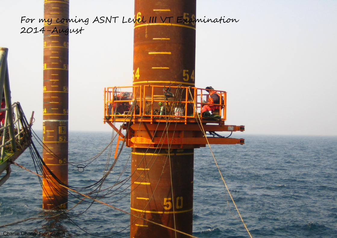
For my coming ASNT Level III VT Examination2014-August
Charlie Chong/ Fion Zhang

At works
Charlie Chong/ Fion Zhang

Reading 4ASNT Nondestructive Handbook Volume 8Visual & Optical testing- Section 4AFor my coming ASNT Level III VT Examination2014-August
Charlie Chong/ Fion Zhang

Fion Zhang2014/August/15
Charlie Chong/ Fion Zhang

SECTION 4BASIC AIDS AND ACCESSORIES FORVISUAL TESTING
Charlie Chong/ Fion Zhang

SECTION 4: BASIC AIDS AND ACCESSORIES FOR VISUAL TESTING
PART 1: BASIC VISUAL AIDS
1.1 Effects of the Test Object
PART 2: MAGNIFIERS
2.1 Range of Characteristics2.2 Low Power Microscopes2.3 Medium Power Systems2.4 High Power Systems
Charlie Chong/ Fion Zhang

PART 3: BORE SCOPES
3.1 Fiber Optic Borescopes3.2 Rigid Borescopes3.3 Special Purpose Borescopes3.4 Typical Industrial Borescope Applications3.5 Borescope Optical Systems3.6 Borescope Construction
Charlie Chong/ Fion Zhang
PART 4: MACHINE VISION TECHNOLOGY
4.1 Lighting Techniques4.2 Optical Filtering '4.3 Image Sensors4.4 Image Processing4.5 Mathematical Morphology4.6 Image Segmentation4.7 Optical Feature Extraction for High Speed Optical Tests4.8 Conclusion
Charlie Chong/ Fion Zhang

PART 5: REPLICATION
5.1 Cellulose Acetate Replication5.2 Silicon Rubber Replicas5.3 Conclusion
Charlie Chong/ Fion Zhang

PART 6: TEMPERATURE INDICATING MATERIALS
6.1 Other Temperature Indicators6.2 Certification of Temperature Indicators6.3 Applications for Temperature Indicators
Charlie Chong/ Fion Zhang

PART 7: CHEMICAL AIDS
7.1 Test Object Selection7.2 Surface Preparation 7.3 Etching7.4 Using Etchants7.5 Conclusion
Charlie Chong/ Fion Zhang

PART 1: BASIC VISUAL AIDS
1.0 General
The human eye is an important component for performing visual nondestructive tests. However, there are situations where the eye is not sensitive enough or cannot access the test site. In these cases mechanical and optical devices can be used to supplement the eye to achieve a complete visual test.
Visual tests comprise five basic elements: the inspector, the test object, an optical instrument, illumination and a recording method. Each of these elements interacts with the others and affects the test results. Training and vision acuity are the two most important factors affecting the visual inspector. According to the American Society of Mechanical Engineers' Boiler and Pressure Vessel Code, Section XI, visual inspectors must be qualified through formal training programs for certification to ensure competency.
Charlie Chong/ Fion Zhang

Keywords:
1. Training and vision acuity are the two most important factors affecting the visual inspector.
2. According to the American Society of Mechanical Engineers' Boiler and Pressure Vessel Code, Section XI, visual inspectors must be qualified through formal training programs for certification to ensure competency.
Charlie Chong/ Fion Zhang

Inspector’s Factors
Charlie Chong/ Fion Zhang

Inspector’s Factors
Charlie C
hong/ Fion Zhang

Inspector’s Factors
Charlie Chong/ Fion Zhang

Levels of vision acuity are determined by eye examination. Approximately 50 percent of Americans over the age of twenty need corrective eyeglasses. In early stages of eyesight deficiency, many people are unaware of their condition- some simply do not want to wear glasses. It is important that borescopes be designed to allow diopter adjustments on the eyepiece. Frequently, wearing glasses is an inconvenience when using a borescope it is difficult to place the eye at the ideal distance from the eyepiece and the view is distorted by external glare and reflections. Rubber eye shields on borescopes are designed to shut out external light but are not as effective when glasses are worn. For these reasons, it is critical that the inspector be able to adjust the instrument without wearing glasses to compensate forvariations in vision acuity.
Charlie Chong/ Fion Zhang
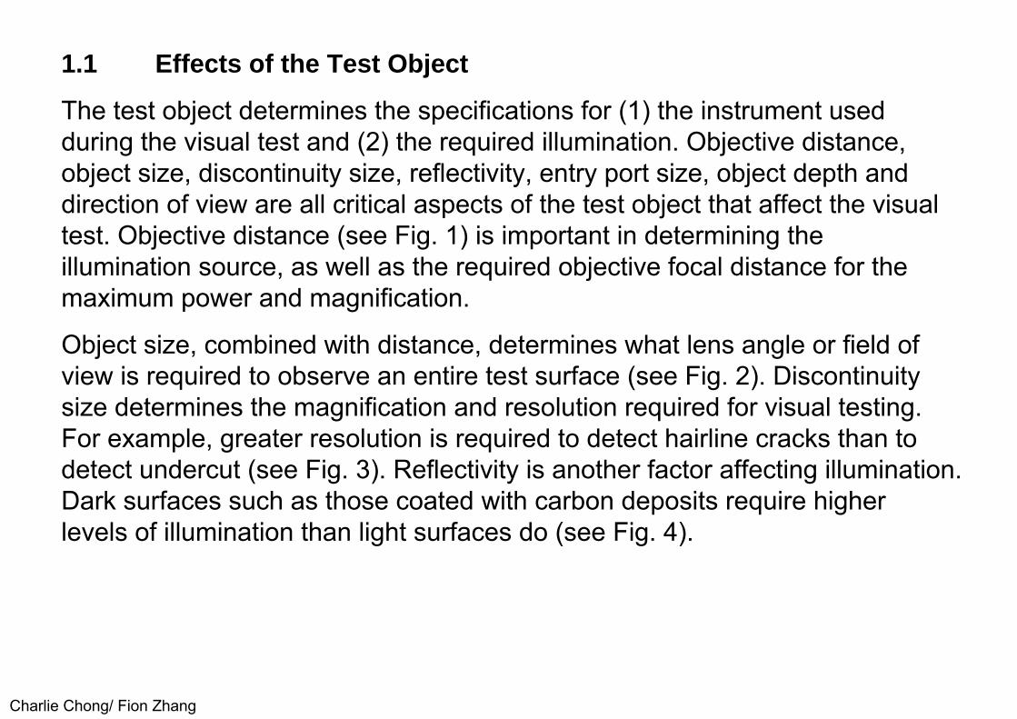
1.1 Effects of the Test Object
The test object determines the specifications for (1) the instrument used during the visual test and (2) the required illumination. Objective distance, object size, discontinuity size, reflectivity, entry port size, object depth and direction of view are all critical aspects of the test object that affect the visual test. Objective distance (see Fig. 1) is important in determining the illumination source, as well as the required objective focal distance for the maximum power and magnification.
Object size, combined with distance, determines what lens angle or field of view is required to observe an entire test surface (see Fig. 2). Discontinuity size determines the magnification and resolution required for visual testing. For example, greater resolution is required to detect hairline cracks than to detect undercut (see Fig. 3). Reflectivity is another factor affecting illumination. Dark surfaces such as those coated with carbon deposits require higher levels of illumination than light surfaces do (see Fig. 4).
Charlie Chong/ Fion Zhang

FIGURE 1. Objective distance (arrows, for direct and side viewing borescopes
Charlie Chong/ Fion Zhang
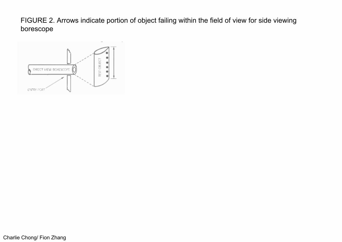
FIGURE 2. Arrows indicate portion of object failing within the field of view for side viewing borescope
Charlie Chong/ Fion Zhang
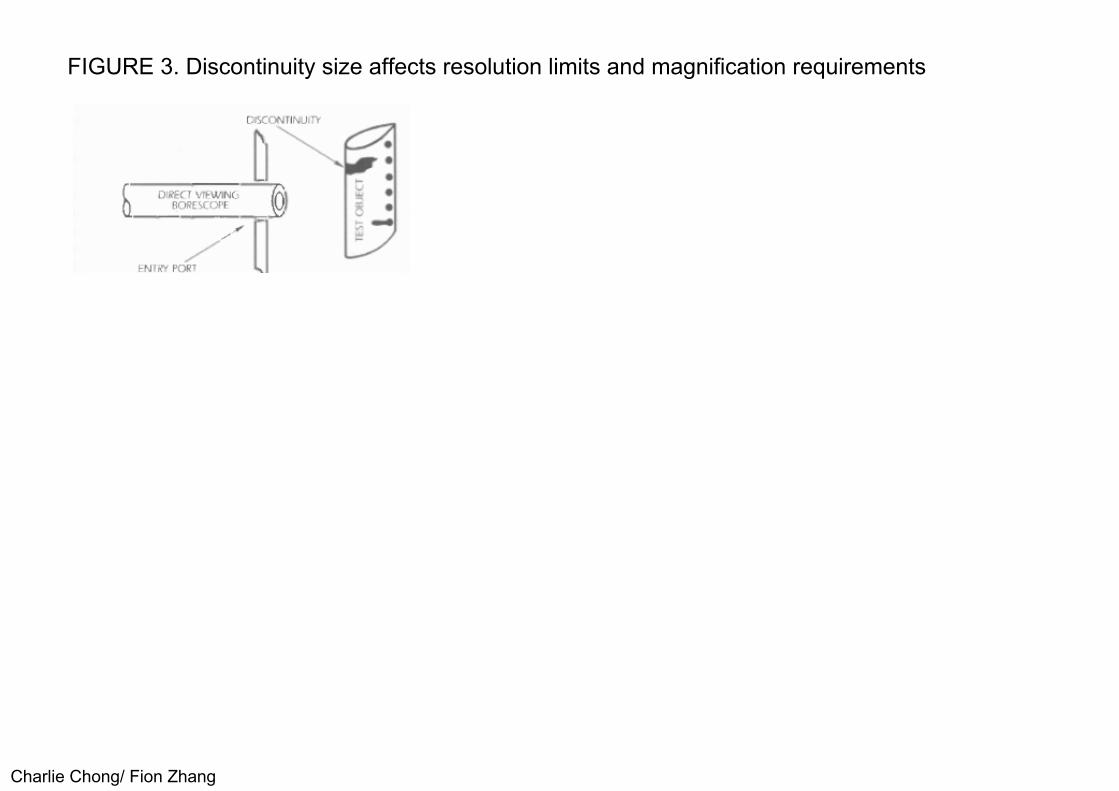
FIGURE 3. Discontinuity size affects resolution limits and magnification requirements
Charlie Chong/ Fion Zhang
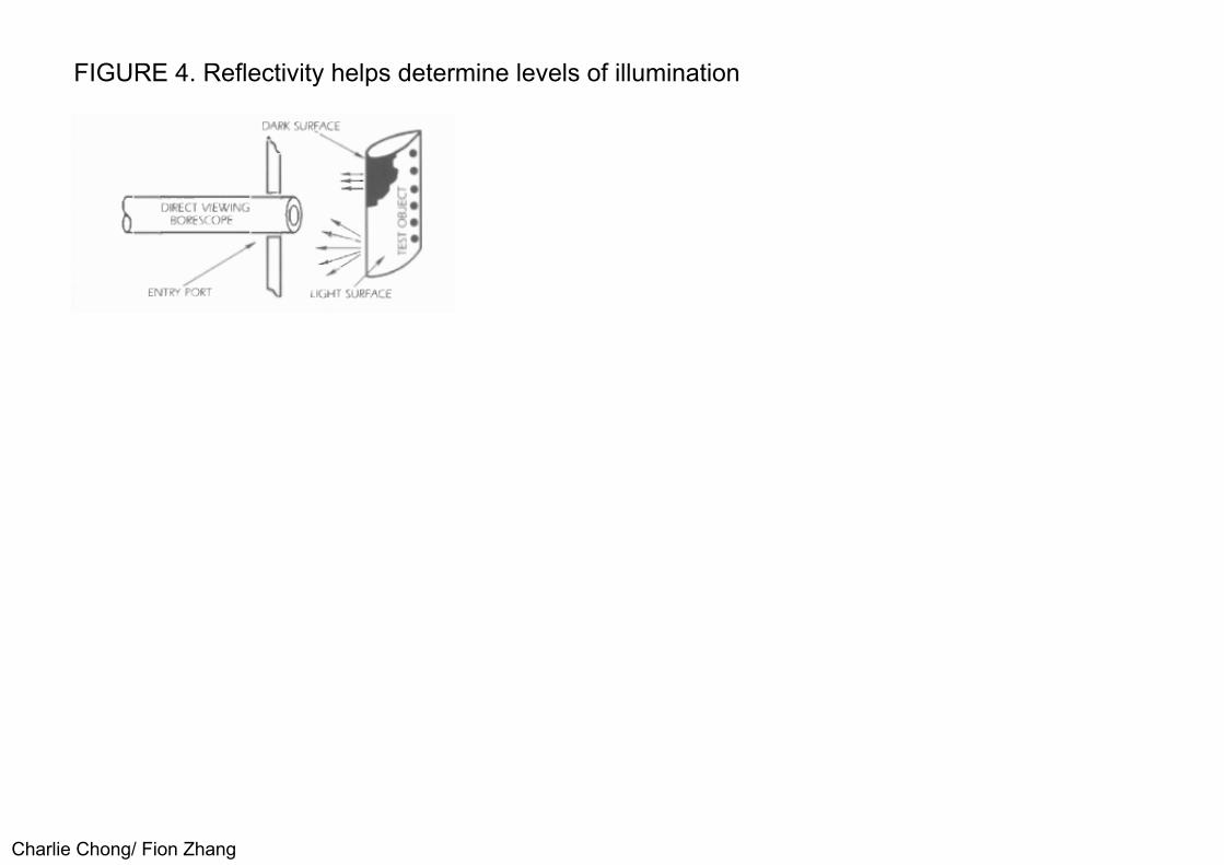
FIGURE 4. Reflectivity helps determine levels of illumination
Charlie Chong/ Fion Zhang

Entry port size determines the maximum diameter of the instrument that can he used for the visual test (see Fig. 5). Object depth affects focusing. If portions of the object are in different planes, then the borescope must have sufficient focus adjustment or depth of field to visualize these different planes sharply (see Fig. 6). Direction of view determines positioning of the borescope, especially with rigid borescopes. Viewing direction also contributes to the required length of the borescope.
Some of the factors affecting visual tests with borescopes are in conflict and compromise is often needed. For example, a wide field of view reduces magnification but has greater depth of field (see Fig. 7). A narrow field of view produces higher magnification but results in shallow depth of field. Interaction of these effects must be considered in determining the optimum setup for detection and evaluation of discontinuities in the test object.
Charlie Chong/ Fion Zhang

FIGURE 6. Object depth (arrows) is a critical factor affecting focus
Charlie Chong/ Fion Zhang
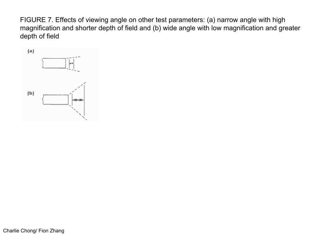
FIGURE 7. Effects of viewing angle on other test parameters: (a) narrow angle with high magnification and shorter depth of field and (b) wide angle with low magnification and greater depth of field
Charlie Chong/ Fion Zhang

Keywords:
1. Entry port size determines the maximum diameter of the instrument,2. If portions of the object are in different planes, then the borescope must
have sufficient focus adjustment or depth of field to visualize these different planes sharply,
3. Direction of view determines positioning of the borescope, especially with rigid borescopes,
4. A wide field of view reduces magnification but has greater depth of field, 5. A narrow field of view produces higher magnification but results in shallow
depth of field.
Charlie Chong/ Fion Zhang

At Works
Charlie Chong/ Fion Zhang

At Works
Charlie Chong/ Fion Zhang

At Works
Charlie Chong/ Fion Zhang

At Works
Charlie Chong/ Fion Zhanghttp://cavemancircus.com/2013/11/26/tribute-majestic-beauty-engines-30-pics/
At Works
Charlie Chong/ Fion Zhang http://cavemancircus.com/2013/11/26/tribute-majestic-beauty-engines-30-pics/
At Works
Charlie Chong/ Fion Zhang

At Works
Charlie Chong/ Fion Zhanghttp://cavemancircus.com/2013/11/26/tribute-majestic-beauty-engines-30-pics/

At Works
Charlie Chong/ Fion Zhang

At Works
Charlie Chong/ Fion Zhang

At Works
Charlie Chong/ Fion Zhang

At Works
Charlie Chong/ Fion Zhang

PART 2: MAGNIFIERS
2.1 Range of Characteristics
2.1.0 General
Magnification as an aid to vision ranges in magnifying power from 1.5 x to 2,000 x . Field coverage of conventional magnifiers ranges from 90 mm (3.5 in.) down to 0.15 mm (0.006 in.) wide. Resolving powers range from 0.05 mm(0.002 in.) to 0.2 μm (0.008 mil). Powers of magnification refer to enlargement in one dimension only. A two-dimensional image magnified x 2, for example, doubles in width and in height though its area quadruples.
The microscope is a typical magnifier. In its simplest form, it is a single biconvex lens in a housing adjustable for focus. Many forms of illumination are available, including bright field, dark field, oblique, polarized, phase contrast and interference.
Charlie Chong/ Fion Zhang

Bi-Convex Microscope
Charlie Chong/ Fion Zhang
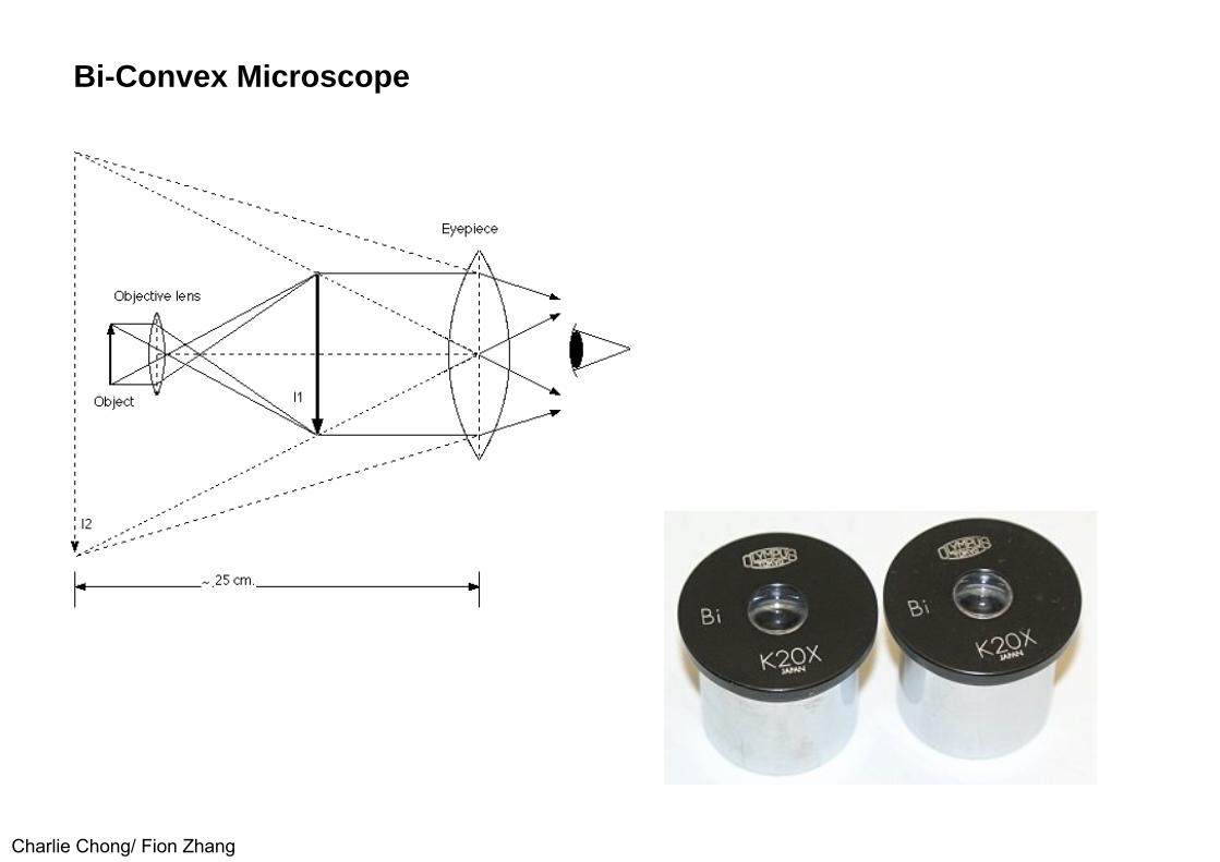
Bi-Convex Microscope
Charlie Chong/ Fion Zhang

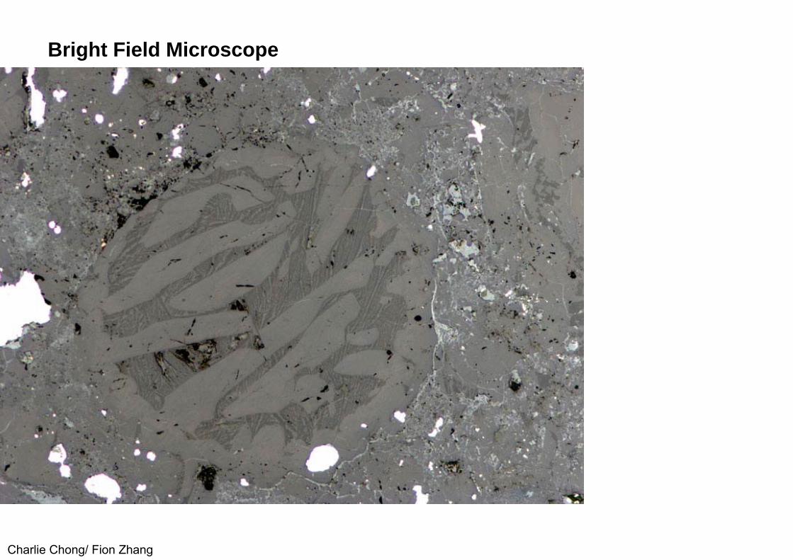
Bright Field Microscope
Charlie Chong/ Fion Zhang

Bright Field Microscope
Charlie Chong/ Fion Zhanghttp://e-materials.ensiacet.fr/domains/d07/doc02/tem.html
Bright Field Microscope
Charlie Chong/ Fion Zhang

Bright Field Microscope
Charlie Chong/ Fion Zhanghttp://item.taobao.com/item.htm?spm=a230r.1.14.84.SgOIEN&id=15135391353&ns=1#detail

Dark Field Microscope
Charlie Chong/ Fion Zhang

Oblique Microscopy
Charlie Chong/ Fion Zhang

Oblique Microscopy
Charlie Chong/ Fion Zhang

Polarized Microscopy
Charlie Chong/ Fion Zhang

Polarized Microscopy
Charlie Chong/ Fion Zhanghttp://micro.magnet.fsu.edu/primer/techniques/polarized/gallery/pages/glauconite1large.html

Interference Microscopy
Charlie Chong/ Fion Zhang

Interference Microscopy
Charlie Chong/ Fion Zhang

Interference Microscopy
Charlie Chong/ Fion Zhang

Interference Microscopy
Charlie Chong/ Fion Zhang
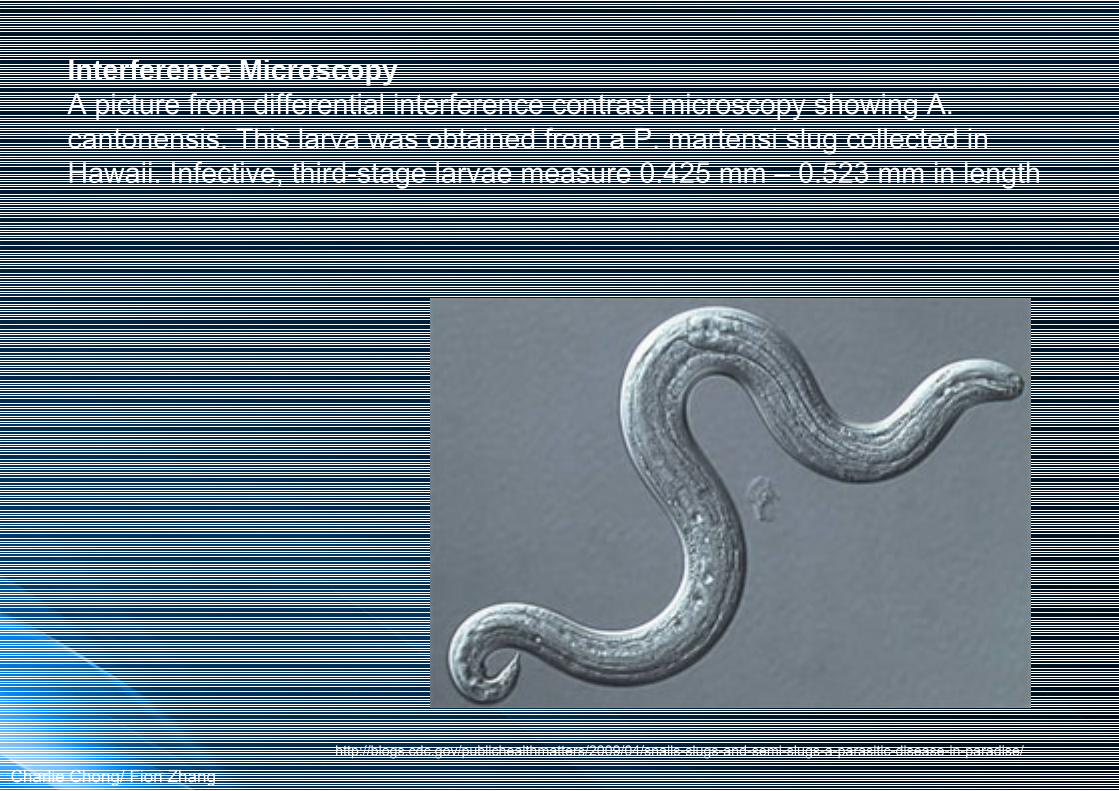
Interference MicroscopyA picture from differential interference contrast microscopy showing A. cantonensis. This larva was obtained from a P. martensi slug collected in Hawaii. Infective, third-stage larvae measure 0.425 mm – 0.523 mm in length
Charlie Chong/ Fion Zhanghttp://blogs.cdc.gov/publichealthmatters/2009/04/snails-slugs-and-semi-slugs-a-parasitic-disease-in-paradise/

Interference Microscopy
Charlie Chong/ Fion Zhang

Interference Microscopy
Charlie Chong/ Fion Zhang

Phase Contrast Microscopy
Charlie Chong/ Fion Zhanghttp://en.wikipedia.org/wiki/Phase_contrast_microscopy

Phase Contrast Microscopy
Charlie Chong/ Fion Zhang http://en.wikipedia.org/wiki/Phase_contrast_microscopy

2.1.1 Conventional Magnifiers and Readers
The major considerations for choosing a magnifier are:
(1) power or magnification, (2) working distance, (3) field ofview, (4) chromatic correction and (5) binocular or monocular vision.
These magnifier attributes are interrelated. A high power magnifier, for example, has a short working distance, a small field of view and cannot he used for binocular observation. A low power magnifier, such as a rectangular reader lens, has a long working distance, a large field of view and can he used for binocular vision. To attain chromatic correction (to eliminate color fringing), the high power lens must be complex. It typically contains a cemented doublet or triplet of different optical glasses. By comparison, the low power reader lens is sufficiently achromatic as a simple lens.
Charlie Chong/ Fion Zhang

Chromatic correction (to eliminate color fringing)
Charlie Chong/ Fion Zhang

Chromatic correction (to eliminate color fringing)
Charlie Chong/ Fion Zhang

Table 1 shows the characteristics of a few typical magnifiers. These values are approximations because eye accommodation can cause each of the values to vary. Except for the reader lens, all magnifiers are used with the eye fairly close to the magnifier, giving the largest field of view. The reader lens is used binocularly and is normally held some distance away from the eyes. Because of its large diameter, the 3.5 x doublet magnifier has as large a field as the 2 x loupe. The double convex lens of the doublet magnifier with its central iris has a comparatively small field. The triplet is a three-element design having excellent optical correction for field coverage and reduction of color fringing. Its resolving power is the limit of detection for fine structures. In comparison, the doublet magnifier can barely differentiate two points 0.025 mm (0.001 in.) apart. There are many variations of these characteristics. Commercial magnifiers can be as high as 30 x in power and there are many special mountings for particular applications.
Charlie Chong/ Fion Zhang
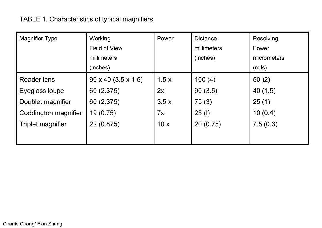
TABLE 1. Characteristics of typical magnifiers
Charlie Chong/ Fion Zhang
50 )2)40 (1.5)25 (1)10 (0.4)7.5 (0.3)
100 (4)90 (3.5)75 (3)25 (I)20 (0.75)
1.5 x2x3.5 x7x10 x
90 x 40 (3.5 x 1.5)60 (2.375)60 (2.375)19 (0.75)22 (0.875)
Reader lensEyeglass loupeDoublet magnifierCoddington magnifierTriplet magnifier
ResolvingPowermicrometers(mils)
Distancemillimeters(inches)
PowerWorkingField of Viewmillimeters(inches)
Magnifier Type
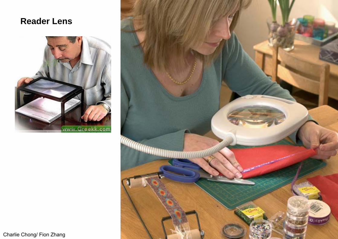
Reader Lens
Charlie Chong/ Fion Zhang

Eyeglass Loupe
Charlie Chong/ Fion Zhang

Eyeglass Loupe
Charlie Chong/ Fion Zhang

Eyeglass Loupe
Charlie Chong/ Fion Zhang

Eyeglass Loupe
Charlie Chong/ Fion Zhang

Doublet Magnifier
Charlie Chong/ Fion Zhang

Triplet Magnifier
Charlie Chong/ Fion Zhang

Coddington magnifier
Charlie Chong/ Fion Zhang
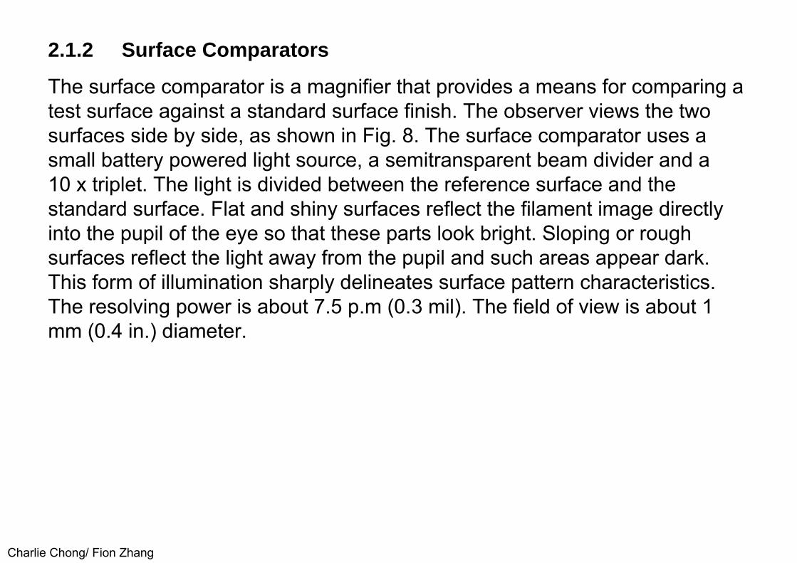
2.1.2 Surface Comparators
The surface comparator is a magnifier that provides a means for comparing a test surface against a standard surface finish. The observer views the two surfaces side by side, as shown in Fig. 8. The surface comparator uses a small battery powered light source, a semitransparent beam divider and a10 x triplet. The light is divided between the reference surface and the standard surface. Flat and shiny surfaces reflect the filament image directly into the pupil of the eye so that these parts look bright. Sloping or rough surfaces reflect the light away from the pupil and such areas appear dark. This form of illumination sharply delineates surface pattern characteristics.The resolving power is about 7.5 p.m (0.3 mil). The field of view is about 1 mm (0.4 in.) diameter.
Charlie Chong/ Fion Zhang

FIGURE 8. The surface comparator: (a) two surfaces magnified for comparison and (b) test setup
Charlie Chong/ Fion Zhang

Other Surface Comparators
Charlie Chong/ Fion Zhang

Other Surface Comparators
Charlie Chong/ Fion Zhang

2.1.3 Measuring Magnifier
A measuring magnifier incorporates a measuring scale that is positioned against the test object to measure tiny details on its flat surfaces (see Fig. 9). A transparent housing permits light to fall on the measured surface. Scales are available for measurements in inches, millimeters and other units (seeFig. 10). The magnifier uses a 7 x triplet lens. The resolving power is about 1 μm (0.04 mil). The diameter of the field of view is about 25 mm (1 in.).
Charlie Chong/ Fion Zhang
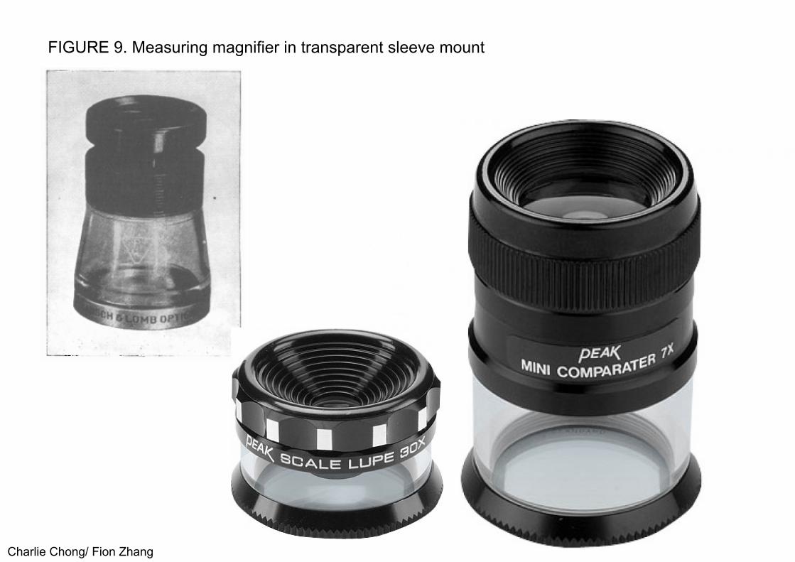
FIGURE 9. Measuring magnifier in transparent sleeve mount
Charlie Chong/ Fion Zhang

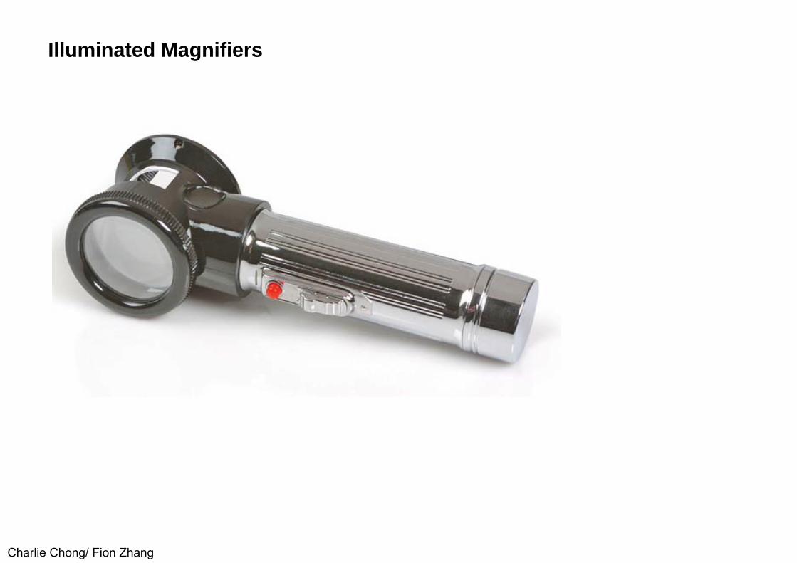
2.1.4 Illuminated Magnifiers
Illuminated magnifiers range from large circular reader lenses, equipped with fluorescent lighting and an adjustable stand, to a small battery powered 10 x magnifier shaped like a pencil. Some illuminated magnifiers can be obtained in either a battery powered model or equipped for 115 V line operation. Such triplet magnifiers give about a 50 mm (2 in.) field of view. Resolving power is about 1.5 μm (0.06 mil).
Charlie Chong/ Fion Zhang
Illuminated Magnifiers
Charlie Chong/ Fion Zhang
2.2 Low Power Microscopes
2.2.0 General
When magnifications above 10 x are required, the short working distance of the magnifier becomes a problem and a low power compound microscope is preferred. Two such magnifiers are described below. Their resolving powers are about 7.5 μm (0.3 mil).
Charlie Chong/ Fion Zhang

2.2.1 Wide Field Tubes
The simplest form of compound microscope is a wide field tube, comprising an objective lens mounted in one end of a tube and an eyepiece in the other. This design is typically supplied either in a tripod sleeve mount or in a simplified microscope stand. Focusing is accomplished by a friction slide fit in a sleeve. The 10 x wide field tube covers a field of 25 mm (1 in.) and has a working distance (the clearance between the objective and test object) of about 80 mm (3.25 in.). The 40 x version has a field of about 6 mm (0.25 in.) and a working distance of about 40 mm (1.625 in.). The image from such a simple microscope is inverted and reversed and is not convenient for hand manipulation of the test object during observation. Wide field tubes are frequently equipped with eyepiece scales to permit measurements in the test object plane.
Charlie Chong/ Fion Zhang

Wide Field Tubes
Charlie Chong/ Fion Zhanghttp://www.lmscope.com/produkt22/LM_Universal_DSLR_Weitfeld_Adapter_Tube30mm_en.shtml

Wide Field Tubes
Charlie Chong/ Fion Zhang

Wide Field Tubes
Charlie Chong/ Fion Zhang

2.2.2 Wide Field Macroscope
The wide field macroscope is similar to a wide field tube, with the same magnification range (10 x to 40 x) and the same mounting and focusing devices. Unlike the wide field tube, the macroscope produces an image that is upright and not reversed, so that manipulation of the test object can beconveniently done during observation.
The prism system that corrects the image also provides an inclined observation tube for more convenient prolonged viewing. The macroscope is often supplied with measuring scales for size determinations.
Charlie Chong/ Fion Zhang

FIGURE 10. Typical measuring scales and reticules (in inches) for the measuring magnifier
Charlie Chong/ Fion Zhang
2.3 Medium Power Systems
2.3.0 General
Typical medium power magnifiers range from 20 x to 100 x in a variety of designs.
Charlie Chong/ Fion Zhang

2.3.1 Wide Field Stereoscopic Microscopes
As can be seen in Fig. 11, the wide field stereoscopic microscope is very complex. It is basically two erect image microscopes, one for each eye, comprising two objectives, two erecting prisms, two inclination prisms and two eyepieces. Furthermore, as shown in the figure, the stereoscopic microscope is usually supplied with several pairs of objectives in a nosepiece so that the power can be changed rapidly. It may also be provided with a glass stage and a substage mirror for transmitted illumination.
The power range of the stereomicroscope is typically 7 x to 150 x , although its usefulness beyond 60 x is limited. The resolving power is about 5 μm (0.2 mil). Field coverage is approximately inverse to the power: at 10 x field coverage is about 25 mm (1 in.). The instrument provides binocular vision, which makes possible its prolonged use for visual testing. Like the macroscopes, manual manipulation during observation is practical.
Charlie Chong/ Fion Zhang

The stereoscopic microscope provides a true view of depth, so that test objects may be inspected in three dimensions. There are many variations in the construction of the stereoscopic microscope. They are sometimes built on stands having long universal joint arms, permitting vertical as well as lateral, horizontal and angular movements, for scanning extended regions of the test object. A single pair or several paired objectives may he supplied and stereoscopic
Charlie Chong/ Fion Zhang

FIGURE 11. Wide field stereoscopic microscope
Charlie Chong/ Fion Zhang

Wide Field Stereoscopic Microscopes
Charlie Chong/ Fion Zhang

2.3.2 Shop Microscope
The shop microscope is similar to a wide field tube. It is a simple tube with an objective near one end and an eyepiece at the other. It has a power of 40 x and contains a built-in light source that may be operated from a battery or 115 V line current. The shop microscope contains a scale permitting direct measurement on the object plane to 0.025 mm (0.001 in.) or estimates to 6 (0.25 mil), over a scale length of 4 mm (0.15 in.). The field of view is 5 mm (0.22 in.) and the resolving power is about 3.3 μm (0.13 mil).
The instrument is extremely lightweight, only 500 g (18 oz) with dry cells. Applications of the shop microscope include on-site tests of plated, painted or polished surfaces; detection of cracks, blowholes and other discontinuities; and measurement of small holes in heading dies, 'gages and other machined components. It also provides a quick method for checking wear in mechanical components. Welding of machine tool frames, piping, structural members, pressure vessels, jigs and fixtures, can be quickly inspected.
Charlie Chong/ Fion Zhang

In finishing and electroplating operations, surface tests with the shop microscope can detect cracks, blister, irregular deposits, pitting and poor quality buffing or polishing. It can reveal slag inclusions and poor surfacing of base metals before plating. On painted surfaces it permits quick and accurate evaluation of quality, uniformity and pigment distribution. In the graphic arts, it is used to check halftones for size, shape and distribution of dots.
Textile mills use shop microscopes for identification of fiber textures, distribution of coloring matter and test of weave, twist and other general characteristics. Fabric finishes, markings, lusters and dye transfers can be inspected for penetration and quality. In the paper industry, the shop microscope is used to check fiber uniformity, evenness of coating and wear of Fourdrinier wires.
Charlie Chong/ Fion Zhang

Shop Microscope
Charlie Chong/ Fion Zhang

Shop Microscope
Charlie Chong/ Fion Zhang

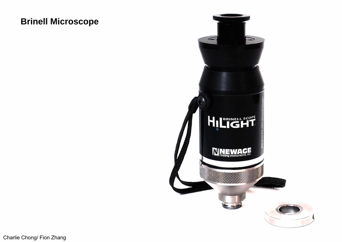
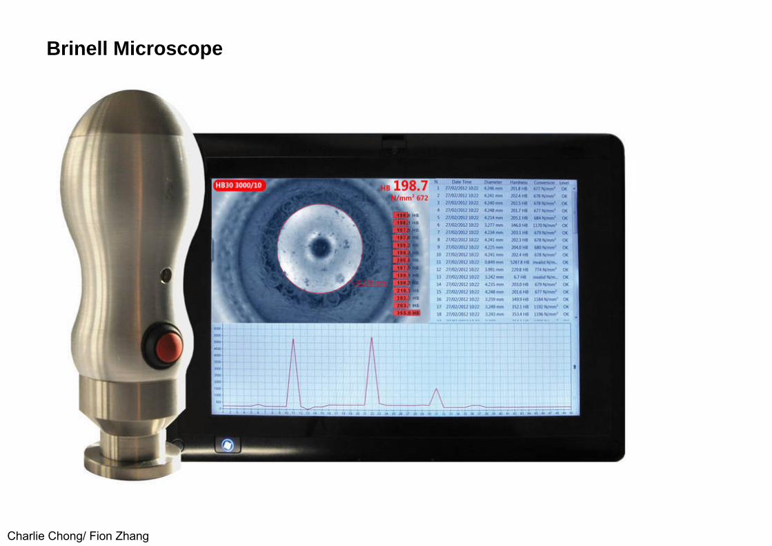
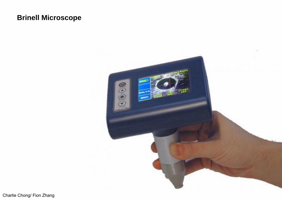
2.3.3 Brinell Microscope
The Brinell microscope is similar to the shop microscope. It is specifically designed for measuring the diameter of an impression made by the ball of a Brinell hardness testing machine. Its magnification is 20 x, the field of view is 8 mm (0.32 in.) and its resolving power is 3.5 μm (0.14 mil). The scale is calibrated to read (in tenths of millimeters) the actual size of the impression over a range of 6 mm.
Focusing is accomplished by rotating the eyepiece in its spiral mount. Adequate illumination of the Brinell depression regardless of the color of the test object, is ensured by an annular mirror in the base of the microscope. The mirror reflects light on the viewing area and the outline of the Brinell impression stands out in contrast. Three types of illumination are available: integral battery in a side tube; 0.3 A, 3.8 V, with 115 V alternating current transformer; and daylight or ordinary room illumination.
Charlie Chong/ Fion Zhang
Brinell Microscope
Charlie Chong/ Fion Zhang

Brinell Microscope
Charlie Chong/ Fion Zhang

Brinell Tester
Charlie Chong/ Fion Zhang

Brinell Microscope
Charlie Chong/ Fion Zhang
Brinell Microscope
Charlie Chong/ Fion Zhang

Brinell Microscope
Charlie Chong/ Fion Zhang

Brinell Microscope
Charlie Chong/ Fion Zhang
Brinell Microscope
Charlie Chong/ Fion Zhang

Brinell Microscope
Charlie Chong/ Fion Zhang

Vicker Hardness Microscope
Charlie Chong/ Fion Zhang

2.4 High Power Systems
2.4.0 General
High power optical systems are used in laboratory, metallurgical, metallographic, polarizing, interference and phase contrast microscopes. The power of such systems ranges from 100 x to 2,000 x
Charlie Chong/ Fion Zhang

2.4.1 Laboratory Microscope
The conventional compound microscope is often called a laboratory microscope. Inclined binocular eyepieces provide ease of vision over prolonged periods of use. Complexity of design for this type of microscope ranges from a simple straight monocular model for student use to elaborate systems for combined visual and photo-micrographic use. A great range of magnification, resolution and field coverage is available, depending on the objective design (see Table 2).
The field coverage, magnification and resolving power given for the laboratory microscope may be roughly applied to other types of high power microscopes. The laboratory microscope is designed principally for transmitted light, so that it is largely useful on transparent or semitransparent materials. It is normally supplied with means for illuminating the test object under controlled conditions to provide the optimum balance between contrast and resolution.
Charlie Chong/ Fion Zhang

Among many available accessories are graduated mechanical stages, eyepiece and stage micrometer scales, filar micrometer eyepieces, comparison eyepieces for viewing two objects under separate microscopes, cross-line eyepieces and various cross-ruled slides for particle counting.
Charlie Chong/ Fion Zhang

Metallurgical Microscope
Charlie Chong/ Fion Zhang

TABLE 2. Ranges of magnification, resolution and field coverage based on objective design
Charlie Chong/ Fion Zhang
20 to 50 x50 to 100x100 to 250 x250 to 750 x750 to 1,500x1,000 to 2,000 x
4.3 (0.17)1.5 (0.06)0.75 (0.029)0.35 (0.014)0.15 (0.006)0.15 (0.006)
3 (0.12)I (0.044)0.6 (0.022)0.4 (0.017)0.2 (0 009)0.2 (0.008)
3.5 x (0.09)10.0 x (0 09)21.0 x (0.50)43.0 x (0.65)97.0x (1.25)90.0 x (1.40)
ApproximateUseful Power Range
Approximate RealField DiameterMillimeters (Inches)
Resolving PowerMicrometers (mills)
Objective (NumericalAperture]

2.4.2 Metallurgical Microscope
The metallurgical microscope is similar to a laboratory microscope with the addition of top or vertical illumination to permit viewing of opaque materials. The vertical illuminator, located directly above the objective, is a semi reflecting, thin, transparent plate. It directs light down through the objective onto the test object. The microscope is normally equipped with a built-in light source and has field and aperture iris controls in the illuminating arm.
Because thick preparations are common in opaque test objects, the stagemay be focused. This also permits the use of an intense external light source, so that focusing can be carried out without upsetting the illumination centering.Although this microscope finds its principal applications in metallurgy, it can he used on almost any opaque material having a reasonably high reflectivity. When test objects are dark by nature (dark plastics, paints, minerals) or have excessive light scattering (fabrics, paper, wood, or biological specimens),a form of incident dark field illumination is superior to regular vertical illumination.
Charlie Chong/ Fion Zhang

2.4.3 Metallographic Microscope
When a camera is built into a metallurgical microscope, it is called a metallographic microscope or a metallograph. In general, the increase in design complexity for a typical metallograph goes far beyond the simple addition of a camera. Most metallographic microscopes also have the following features.
1. They are built on a stand with concealed shock absorbers.2. They use an intense light source, often an automatic carbon arc.3. They use an inverted stand so that the test object need not be plane
parallel (the test object is face down on the stage).4. They have viewing screens for prolonged visual tasks such as dirt count or
grain size measurements.5. They have bright field, dark field and polarized light illumination for diverse
applications.
Charlie Chong/ Fion Zhang

Metallographic Microscope
Charlie Chong/ Fion Zhang

2.4.4 Polarizing Microscope
The addition of two polarizing elements and a circular stage converts a laboratory microscope into an elementary polarizing microscope. A polarizing element is a device that restricts light vibration to a single plane. This form of light is useful for studying most materials with directional optical properties, including fibers, crystals, sheet plastic and materials under strain. As such materials are rotated between crossed polarizers on the microscope stage, they change color and intensity in a way that is related to their directionalproperties.
The polarizing microscope normally has other added features,beyond the polarizing elements and circular stage. Much work, for example, requires study of crystal properties or minerals in three dimensions. The simplest of these accessories is the Bertrand lens, which focuses an image ofthe objective aperture in the eyepiece. In the aperture is a chart of crystal properties in many directions. For more quantitative work, a universal stage is used, on which the crystal can be rotated around one of five axes through its center. The amount of rotation is then measured.
Charlie Chong/ Fion Zhang

Polarizing Microscope on liquids
Charlie Chong/ Fion Zhang

Polarizing Microscope
Charlie Chong/ Fion Zhang

Polarizing Microscope on Liquid Crystals
Charlie Chong/ Fion Zhanghttp://news.science360.gov/obj/pic-day/6a45e444-9b2d-45b6-83ca-b9043397384c/polarization-microscope-image-liquid-crystals

Polarizing Microscope
Charlie Chong/ Fion Zhang
http://www.ebay.com/itm/Binocular-Polarizing-Microscope-40x-640x-/140927225743

Polarizing Microscope
Charlie Chong/ Fion Zhang

2.4.5 Interference Microscope
The interference microscope is a tool using the wavelength of light as a unit of measure for surface contour and other characteristics. In one form of interference microscope, the stage is inverted and the test object is placed face downward. The image appears as a contour map, with a separationof one half-wave or about 0.25 μm (0.01 mil) between contour lines. Extremely precise measurements can be made with such equipment.
Applications of the interference microscope include the measurement, testing and control of very fine finishes, including highly polished or glossy finished surfaces, where the degree of surface roughness is within a few wavelengthsof light. With coarser surfaces, the contour lines are close together and interpretation is difficult. An advantage of the interference microscope is that the test object is not moved manually during inspection. A considerably less elaborate device called an interference
Charlie Chong/ Fion Zhang
objective is also available as an accessory to the metallurgical microscope. This objective has a small, metallized glass mounted in contact with the test object and adjustable for tilt to control fringe spacing. The disadvantage of the interference objective is that the test surface must be moved manually during inspection. Otherwise, its test results are virtually the same as those from an interference microscope.
Charlie Chong/ Fion Zhang
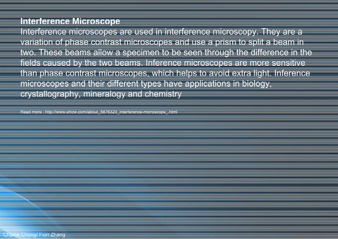
Interference MicroscopeInterference microscopes are used in interference microscopy. They are a variation of phase contrast microscopes and use a prism to split a beam in two. These beams allow a specimen to be seen through the difference in the fields caused by the two beams. Inference microscopes are more sensitive than phase contrast microscopes, which helps to avoid extra light. Inference microscopes and their different types have applications in biology, crystallography, mineralogy and chemistry
Read more : http://www.ehow.com/about_5876329_interference-microscope_.html
Charlie Chong/ Fion Zhang

Interference Microscope
Charlie Chong/ Fion Zhang

Interference Microscope
Charlie Chong/ Fion Zhang

Interference Microscope
Charlie Chong/ Fion Zhang
2.4.6 Phase Contrast Microscope
Completely transparent materials with refractive index discontinuities can be only faintly seen in a normal microscope. Such index discontinuities are readily visible in a phase contrast microscope. Figure 12 shows the two additional optical elements needed to convert a normal microscope to a phase contrast microscope. An annular diaphragm located below the condenser is imaged into an annular phase shifting element in the objective.
The combined effect of the diffracted and un-diffracted light transmitted by this phase shifting element produces contrast in a completely transparentobject. The phase contrast microscope is limited to uses with transparent materials having very small index discontinuities. If the index discontinuities are gross, a normal microscope is used for visual inspection. Extensive work with living tissues and cells has been done with phase contrast devices.
Charlie Chong/ Fion Zhang
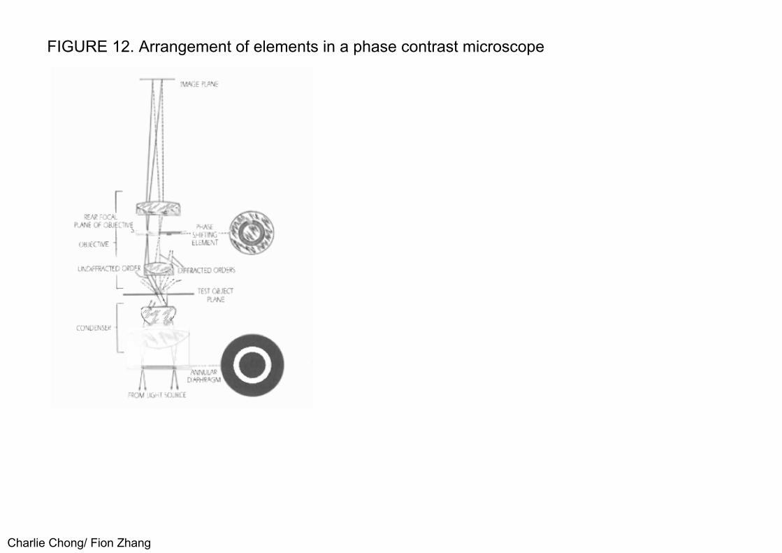
FIGURE 12. Arrangement of elements in a phase contrast microscope
Charlie Chong/ Fion Zhang
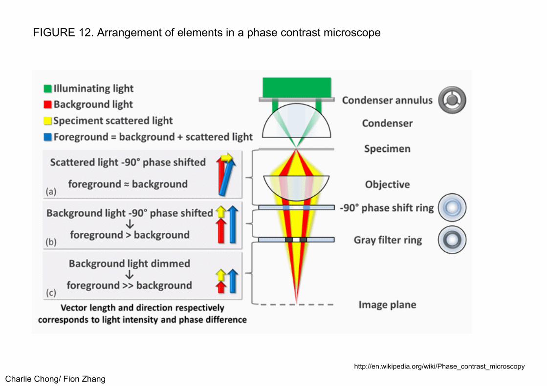
FIGURE 12. Arrangement of elements in a phase contrast microscope
Charlie Chong/ Fion Zhanghttp://en.wikipedia.org/wiki/Phase_contrast_microscopy

FIGURE 12. Arrangement of elements in a phase contrast microscope
Charlie Chong/ Fion Zhanghttp://en.wikipedia.org/wiki/Phase_contrast_microscopy
Phase contrast microscopy is an optical microscopy technique that converts phase shifts in light passing through a transparent specimen to brightness changes in the image. Phase shifts themselves are invisible, but become visible when shown as brightness variations. When light waves travels through a medium other than vacuum, interaction with the medium causes the wave amplitude and phase to change in a manner dependent on properties of the medium. Changes in amplitude (brightness) arise from the scattering and absorption of light, which is often wavelength dependent and may give rise to colors. Photographic equipment and the human eye are only sensitive to amplitude variations. Without special arrangements, phase changes are therefore invisible. Yet, phase changes often carry important information.
Keywords:
Phase Changes
Charlie Chong/ Fion Zhanghttp://en.wikipedia.org/wiki/Phase_contrast_microscopy

Phase contrast microscopy is particularly important in biology. It reveals many cellular structures that are not visible with a simpler bright field microscope, as exemplified in Figure 1. These structures were made visible to earlier microscopists by staining, but this required additional preparation and killed the cells. The phase contrast microscope made it possible for biologists to study living cells and how they proliferate through cell division.[1] After its invention in the early 1930s,[2] phase contrast microscopy proved to be such an advancement in microscopy, that its inventor Frits Zernike was awarded the Nobel prize (physics) in 1953.
Charlie Chong/ Fion Zhang

Phase contrast microscopy
Charlie Chong/ Fion Zhang

Phase contrast microscopy
Charlie Chong/ Fion Zhang
More Reading on Phase Contrast Microscopy:
To understand the phase contrast microscope, it is first necessary to review the ordinary compound light microscope. It features a set of components that function together to transmit light from the subject being studied to the observer's eye. From the bottom up, these are the light source, the substagecondenser, the mechanical stage, the glass slide holding the subject matter, the objective lens and the eyepiece lens.
Viewing a specimen through the ordinary compound light microscope---called the bright field microscope---involves illuminating the object from below through an opening in the stage. The user selects an objective lens of the desired power by turning the nosepiece just above the microscope's stage. Peering through the microscope's eyepiece, the operator then adjusts the focus controls to bring the specimen into clear view.
Charlie Chong/ Fion Zhang

As the name suggests, the difference between the ordinary light microscope (the bright field microscope) and the phase contrast microscope concerns contrast. Living organisms or living cells tend to have low contrast, making details of their structure difficult to see. Some structures in a specimen, like the cilia of a paramecium or the flagellum of a euglena for example, may not have very much contrast compared to the surrounding medium. They would therefore not show up very well under regular bright field microscopy. Treating that specimen with certain stains can compensate for this. But the tradeoff is that this will kill the cells, preventing the user from observing details of a living cell.
A phase contrast microscope, on the other hand, would correct for this by producing the desired contrast without killing the living cells. It seems to magically transform the view of a specimen showing very little contrast or detail in the bright field microscope into a dramatic image.
Charlie Chong/ Fion Zhang

The phase contrast microscope is essentially an ordinary light microscope with all the same basic components. The difference is that the phase contrast microscope features something called a phase plate. This plate is situated in the light path between the subject matter being viewed and the viewer's eye (actually in the objective lens housing). Additionally, a so-called phase ring or annulus is installed onto the substage condenser (the device that focuses light onto the specimen).
The optical physics involved in the process can be a bit difficult. But suffice it to say that the phase contrast device alters the wavelengths of light that are traveling through the medium containing the specimen and the specimen itself. This wavelength alteration produced by the combination of the phase plate and the phase ring or annulus generates the desired contrast. Regular bright field light microscopes can be converted to phase contrast microscopes. This is done by installing the phase ring and objective lenses with the requisite phase plates manufactured into them.
Read more : http://www.ehow.com/how-does_5150971_phase-contrast-microscope-work.html
Charlie Chong/ Fion Zhang

Phase Contrast Microscopy
Charlie Chong/ Fion Zhang

Phase Contrast Microscopy
Charlie Chong/ Fion Zhang

Phase Contrast Microscopy
Charlie Chong/ Fion Zhang

Phase Contrast Microscopy
Charlie Chong/ Fion Zhang

PART 3: BORESCOPES
3.1 Fiber Optic Borescopes
3.1.0 General
The industrial fiber optic borescope is a flexible, layered sheath protecting two fiber optic bundles, each comprising thousands of glass fibers. One bundle serves as the image guide and the other bundle helps illuminate the test object. Light travels only in straight lines but optical glass fibers bend light by internal reflection and so can carry light around corners (see Fig. 13). Such fibers are 9 to 30 μm (0.4 to 1.2 mil) in diameter or roughly one-tenth the thickness of a human hair.
A single fiber transmits very little light, but thousands of fibers may be bundled for transmission of light and images. To prevent the light from diffusing, each fiber consists of a central core of high quality optical glass coated with a thin layer of another glass with a different refractive index (Fig. 14).
Charlie Chong/ Fion Zhang

This cladding acts as a mirror- all light entering the end of the fiber is reflected internally as it travels (Fig. 13) and cannot escape by passing through the sides to an adjacent fiber in the bundle.
Although the light is effectively trapped within each fiber, not all of it emerges from the opposite end. Some of the light is absorbed by the fiber itself and the amount of absorption depends on the length of the fiber and its optical quality. For example, plastic fiber can transmit light and is less expensive to produce than optical glass but plastic is less efficient in its transmission and unsuitable for use in fiber optic borescopes.
Keywords:
Plastid fibersOptical glass fibers
Charlie Chong/ Fion Zhang

Fiber Optic
Charlie Chong/ Fion Zhang

FIGURE 13. Internal reflection of light in an optic fiber can be used to move the light path in a curve
Charlie Chong/ Fion Zhang

FIGURE 14. Light paths in fiber bundles: (a) uncoated fibers allow light to travel laterally through the bundle and (b) coated fibers restrict the light's path to its original fiber
Charlie Chong/ Fion Zhang

3.1.1 Fiber Image Guides
The fiber bundle used as an image guide (see Fig. 15) carries the image formed by the objective lens at the distal end or tip of the borescope hack to the eyepiece. The image guide must be a coherent bundle: the individual fibers must be precisely aligned so that they are in identical relative positionsat their terminations. Image guide fibers range from 9 to 17 μm (0.35 to 0.67 mil) in diameter. Their size is one of the factors affecting resolution, although the preciseness of alignment is far more important. Note that a real image is formed on both highly polishedfaces of the image guide. Therefore, to focus a fiber optic borescope for different distances, the objective lens at the tip must be moved in or out, usually by remote control at the eyepiece section. A separate diopteradjustment at the eyepiece is necessary to compensate for differences in eyesight.
Charlie Chong/ Fion Zhang

Fiber Image Guides
Charlie Chong/ Fion Zhang

Fiber Image Guides
Charlie Chong/ Fion Zhang

Fiber Image Guides
Charlie Chong/ Fion Zhang

FIGURE 15. Optical fiber bundle used as an image guide
Charlie Chong/ Fion Zhang

3.1.2 Fiber Light Guides
Another fiber bundle carries light from the an external high intensity source to illuminate the test object. This is called the light guide bundle and is noncoherent (see Fig. 16). These fibers are about 30 μm (1.2 mil) in diameterand the size of the bundle is determined by the diameter of the scope.Fiber optic borescopes usually have a controllable bending section near the tip so that the inspector can direct the borescope during testing and can scan an area inside the test object. Fiber optic borescopes are made in a variety of diameters, some as small as 3.7 mm (0.15 in.), in lengths up to 10 m (30 ft), and with a choice of viewing directions at the tip.
Charlie Chong/ Fion Zhang

FIGURE 16. Diagram of a typical fiber optic borescope
Charlie Chong/ Fion Zhang

Fiber Image
Charlie Chong/ Fion Zhang
3.2 Rigid Borescopes
The rigid borescope (see Fig. 17) was invented to inspect the bore of rifles and cannons. It was a thin telescope with a small lamp at the top for illumination. Most rigid borescopes now use a fiber optic light guide system as an illumination source.
The image is brought to the eyepiece by an optical train consisting of an objective lens, sometimes a prism, relay lenses and an eyepiece lens. The image is not a real image but an aerial image: it is formed in the air between the lenses. This means that it is possible to both provide diopter correction for the observer and to control the objective focus with a single adjustment to the focusing ring at the eyepiece.
Charlie Chong/ Fion Zhang

Rigid Borescopes
Charlie Chong/ Fion Zhang

FIGURE 17. Typical lens system in a rigid borescope
Charlie Chong/ Fion Zhang

3.2.1 Focusing a Rigid Borescope
The focus control in a rigid borescope greatly expands the depth of field over nonfocusing or fixed focus designs. At the same time, focusing can help compensate for the wide variations in eyesight among inspectors. Figures 18 and 19 emphasize the importance of focus adjustment for expanding the depth of field. Figure 18 was taken at a variety of distances with fixed focus. Figure 19 was taken at the same distances as in Fig. 18 but with a variablefocus, producing much sharper images.
Charlie Chong/ Fion Zhang

FIGURE 18. Borescope images for a variety of distances with fixed focus (see Fig. 19): (a) at 75mm (3 in.), (b) at 200 mm (8 in.) and (c) at 300 mm (12 in.)
Charlie Chong/ Fion Zhang

FIGURE 19. Borescope images with variable focus (see Fig. 18): (a) 75 mm (3 in.), (b) 200 mm (8 in.) and (c) 300 mm (12 in.)
Charlie Chong/ Fion Zhang

Borescopic Inspection
Charlie Chong/ Fion Zhang

3.2.2 Need for Specifications
Because rigid borescopes lack flexibility and the ability to scan areas, specifications regarding length, direction of view and field of view become more critical for achieving a valid visual test. For example, the direction of view should always be specified in degrees rather than in letters or words such as north, up, forward, or left. Tolerances should also be specified.
Some manufacturers consider the eyepiece to be zero degrees and therefore a direct view rigid borescope (Fig. 20a) is 180 degrees. Other manufacturers start with the borescope tip as zero degrees and then count back toward the eyepiece, making a direct-view 0 degrees.
Charlie Chong/ Fion Zhang

FIGURE 20. Borescope direction of view: (a) direct, (b) side, (c) forward oblique and (diretrospective
Charlie Chong/ Fion Zhang

3.2.3 Setup of a Rigid Borescope
To find the direction and field of view during visual testing with a rigid borescope, place a protractor scale on a board or worktable. Position the borescope carefully so it is parallel to the zero line, with the lens directly over the center mark on the protractor. Remember that the optical center of a borescope is usually 25 to 50 mm (1 to 2 in.) behind the lens window.
By sighting through the borescope, stick pins into the board at the edge of the protractor to mark the center and both the left and right edges of the view field. This simple procedure gives both the direction of view and the field of view (see Figs. 21 and 22).
Charlie Chong/ Fion Zhang

FIGURE 21. Field of view for a rigid borescope
Charlie Chong/ Fion Zhang

FIGURE 22. Field of view width for varying distances
Charlie Chong/ Fion Zhang
3.2.4 Mini-borescope
One variation of the rigid borescope is called the mini-borescope (see Fig. 23). In this design, the relay lens train is replaced with a single, solid fiber. The fiber diffuses ions in a parabola from the center to the periphery of the housing, giving a graded index of refraction. Light passes through the fiber and at specific intervals an image is formed. The solid fiber is about 1 mm (0.4 in.) in diameter, making it possible to produce high quality and thin rigid borescopes from 1.7 to 2.7 mm (0.07 to 0.11 in.) in diameter. The lens aperture is so small that the lens has an infinite depth of field (like a pinhole camera) and no focusing mechanism is needed.
Charlie Chong/ Fion Zhang

FIGURE 23. Mini-borescope wide angle lens: (a) general shape and (la) lens detail
Charlie Chong/ Fion Zhang

3.2.5 Accessories
Many accessories are available for rigid borescopes. Instant cameras, 35 mm cameras, and video cameras can be added to provide a permanent record of a visual test. Closed circuit television displays, with or without video tape, arecommon as well. Also available are attachments at the eyepiece permitting dual viewing or right angle viewing for increased accessibility.
Charlie Chong/ Fion Zhang
3.3 Special Purpose Borescopes
Angulated borescopes are available with forward oblique, right angle or retrospective visual systems. These instruments usually consist of an objective section with provision for attaching an eyepiece at right angles to the objective section's axis. This permits inspection of shoulders or recessesin areas not accessible with standard borescopes. Calibrated borescopes are designed to meet specific test requirements. The external tubes of these instruments can be calibrated to indicate the depth of insertion during a test.Borescopes with calibrated reticles are used to determine angles or sizes of objects in the field when held at a predetermined working distance.
Charlie Chong/ Fion Zhang

Panoramic borescopes are built with special optical systems to permit rapid panoramic scanning of internal cylindrical surfaces of tubes or pipes.Wide field borescopes have rotating objective prisms to provide fields of view up to 120 degrees. One application of wide field borescopes is the observation of models in wind tunnels under difficult operating conditions.Ultraviolet borescopes are used during fluorescent magnetic particle and fluorescent penetrant tests. These borescopes are equipped with ultraviolet lamps, filters and special transformers to provide the necessary wavelengths.Waterproof and vapor proof borescopes are used for internal tests of liquid, gas or vapor environments. They are completely sealed and impervious to water or other types of liquid. Water cooled or gas cooled borescopes are used for tests of furnace cavities, jet engine test cells and for other high temperature applications.
Charlie Chong/ Fion Zhang

Panoramic borescopes
Charlie Chong/ Fion Zhang

3.4 Typical Industrial Borescope Applications
3.4.1 Aviation Industry
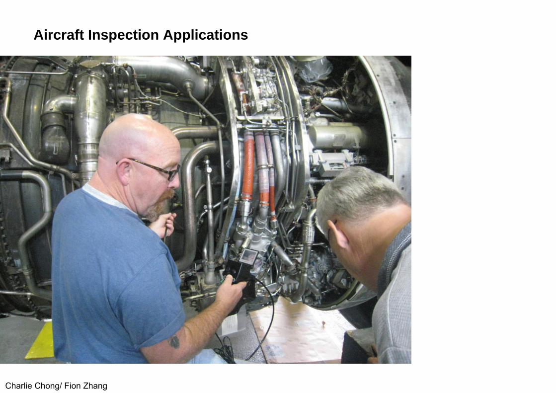
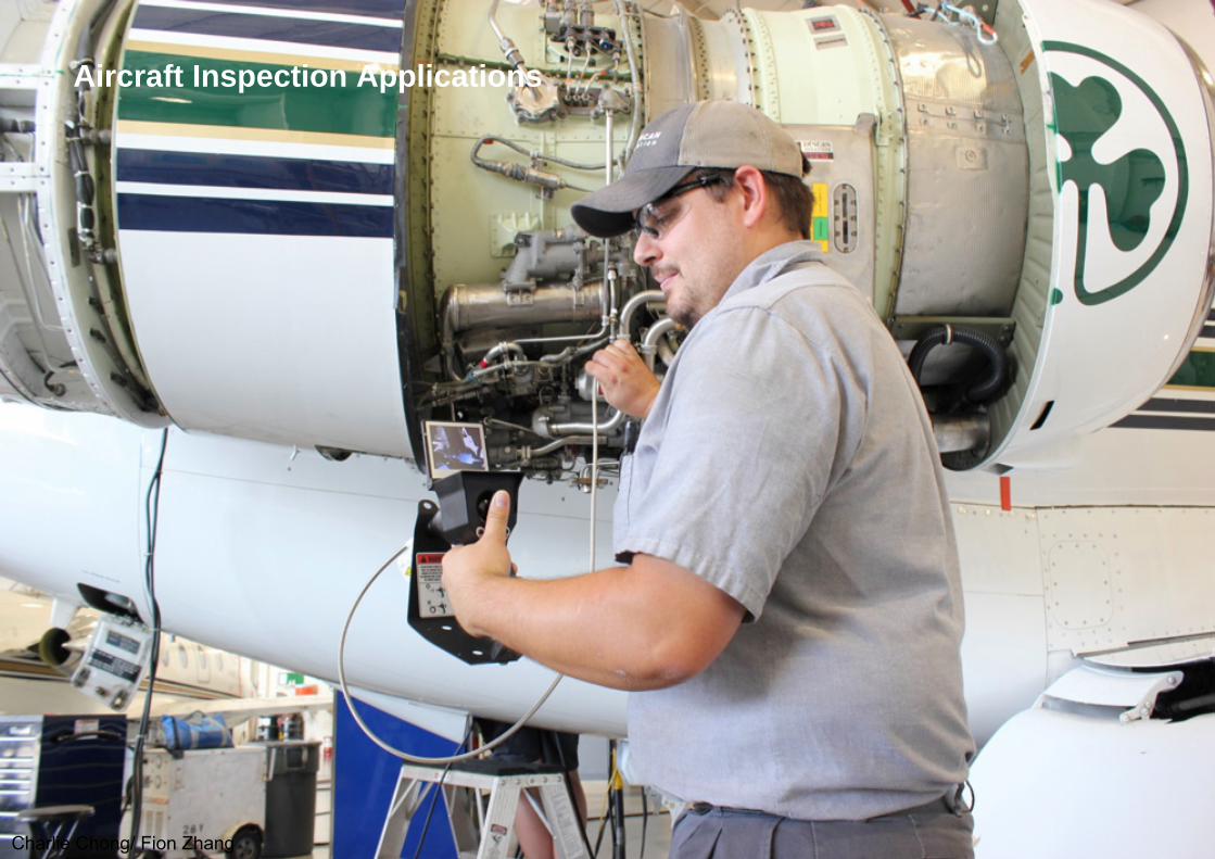
The use of borescopes for tests of airplane engines and other components without disassembly has resulted in substantial savings in costs and time. A borescope of 11 mm (0.44 in.) diameter by 380 mm (15 in.) working length can be used by maintenance and service departments for visual testing of engines through spark plug openings, without dismantling the engines. An excellent view of the cylinder wall, piston head, valves and valve seats is possible and several hundred hours of labor are saved for each engine test. Spare engines in storage can also be inspected for corrosion of cylinderwall surfaces.
Charlie Chong/ Fion Zhang

Aircraft propeller blades are visually tested during manufacture. The entire welded seam of a blade can be inspected internally for cracks and other discontinuities. Propeller hubs, reverse pitch gearing mechanisms, hydraulic cylinders, landing gear mechanisms and electrical components also canbe inspected with borescopes. Aircraft wing spars and struts are inspected for evidence of fatigue cracks and rivets and wing sections cam be tested visually for corrosion. Borescopes used for tests of internal wing tank surfaces and wing corrugations subject to corrosion have saved airlines large sums of money by reducing the time aircraft are out of service.
Charlie Chong/ Fion Zhang

Aircraft Inspection Applications
Charlie Chong/ Fion Zhang

Aircraft Inspection Applications
Charlie Chong/ Fion Zhang

Aircraft Inspection Applications
Charlie Chong/ Fion Zhang
Aircraft Inspection Applications
Charlie Chong/ Fion Zhang
Aircraft Inspection Applications
Charlie Chong/ Fion Zhang

3.4.2 Automotive Industry
Borescopes are widely used in the manufacturing and maintenance divisions of the automotive industry. Engine cylinders can be examined through spark plug holes without removing the cylinder head. The cylinder wall, valves andpiston head can be visually tested for excess wear, carbon deposits and surface discontinuities. Crankcases and crankshafts are examined through wall plug openings without removing the crankcase. Transmissions and differentials are similarly inspected.
Borescopes are also useful for locating discontinuities such as cracks or blowholes in castings and forgings. Machined components such as cross bored holes can be examined for internal discontinuities. Borescopes are used to inspect cylinders for internal surface finish after honing. Tapped holes,shoulders or recesses also can be observed. Inaccessible areas of hydraulic systems, small pumps, motors and mechanical or electrical assemblies can be visually tested without dismantling the engine.
Charlie Chong/ Fion Zhang

Automotive Industry
Charlie Chong/ Fion Zhang

3.4.3 Machine Shops
Borescopes find applications in production machine shops, tool and die departments and in ferrous, nonferrous and alloy foundries. In production machine operations, horescopes of various sizes and angles of view are used to examine internal holes, cross bored holes, threads, internal surface finishes and various inaccessible areas encountered in machine and mechanical assembly operations. Specific examples are visual tests of machine gun barrels, rifle bores, cannon bores, machine equipment and hydraulic cylinders. In tool and die shops, borescopes are used to examineinternal finishes, threads, shoulders, recesses, dies, jigs, fixtures, fittings and the internal mating of mechanical parts. In foundries, horescopes are widely used for internal inspections to locate discontinuities, cracks, porosity and blowholes. Borescopes are also used for tests of many types of defense materials, including the internal surface finish of rocket heads, rocket head seats and guided missile components.
Charlie Chong/ Fion Zhang

Machine Shops
Charlie Chong/ Fion Zhang

3.4.4 Power Plants
In steam power plants, borescopes are used for visual tests of boiler tubes for pitting, corrosion, scaling or other discontinuities. Borescopes used for this type of work are usually made in 2 or 3 m (6 or 9 ft) sections. Each section is designed so that it can be attached to the preceding section, providing an instrument of any required length. Other borescopes are used to examine turbine blades, generators, motors, pumps, condensers, control panels andother electrical or mechanical components without dismantling. In nuclear plants, horescopes offer the advantage that the inspector can be in a low radiation field while the distal, or sensor, end is in a high radiation field.
Charlie Chong/ Fion Zhang

3.4.5 Chemical Industry
Visual tests of high pressure distillation units are used to determine the internal condition of tubes or headers. Evaporation tubes, fractionation units, reaction chambers, cylinders, retorts, furnaces, combustion chambers, heatexchangers, pressure vessels and many other types of chemical process equipment are inspected with borescopes or extension borescopesTank cars are inspected for internal rust, corrosion and the condition of outlet valves. Cylinders and drums can be examined for internal conditions such as corrosion, rust or other discontinuities.
Charlie Chong/ Fion Zhang

3.4.6 Petroleum Industry
Borescopes are used for visual tests of high pressure catalytic cracking units, distillation equipment, fractionation units, hydrogenation equipment, pressure vessels, retorts, pumps and similar process equipment. Use of the borescopein the examination of such structures is doubly significant. Not only does it allow the examination of inaccessible areas without the lost time and expense incurred in dismantling, it avoids breakdown and the ensuing costly repair.
Charlie Chong/ Fion Zhang

3.5 Borescope Optical Systems
Borescopes are precise optical devices containing a complex system of prisms, achromatic lenses and plain lenses that pass light to the observer with high efficiency. An integral light source is usually located at the objective end of the borescope to provide illumination for the test object.
Charlie Chong/ Fion Zhang

3.5.1 Angles of Vision
To meet a wide range of visual testing applications, borescopes are available in various diameters and working lengths to provide various angles of vision for special requirements. The most common types of vision are: (1) right angle, (2) forward oblique, (3) direct and (4) retrospective (see Fig. 20).These types of vision are characterized by different angles of obliquity for the central ray of the visual field, with respect to the forward direction of the borescope axis (see Table 3).
Charlie Chong/ Fion Zhang

TABLE 3. Comparison of vision types and angles of obliquity
Charlie Chong/ Fion Zhang

3.5.2 General Characteristics
Desirable properties of borescopic systems are large field of vision, no image distortion, accurate transmission of color values and adequate illumination. The brightest images are obtained with borescopes of large diameter and short length. As the length of the borescope is increased, the image becomes less brilliant because of light losses from additional lenses required to transmit the image. To minimize such losses, lenses are typically coated with anti reflecting layers to provide maximum light transmission.
Charlie Chong/ Fion Zhang

3.5.3 Optical Components
The optical system of a borescope consists of an objective, a middle lens system, correcting prisms and an ocular section (see Fig. 24). The objective is an arrangement of prisms and lenses mounted closely together. Its design determines the angle of vision, the field of view and the amount of light gathered by the system.
The middle lenses conserve the light entering the system and conduct it through the borescope tube to the eye with a minimum loss in transmission. Design of the middle lenses has an important effect on the character of the image. For this reason, the middle lenses are achromatic, each lens being composed of two elements with specific curvatures and indexes of refraction. This design preserves sharpness of the image and true color values.
Depending on the length of the borescope, the image may need reversal or inversion or both, at the ocular. This is accomplished by a correcting prism within the ocular for borescopes of small diameter and by erecting lenses forlarger designs.
Charlie Chong/ Fion Zhang

3.5.4 Depth of Focus, Field of View and Magnification
The depth of focus for a borescopic system is inverselyrelated to the numerical aperture N.
N = n sin a (Eq. 1)
Where:n = the refractive index of the object space; anda = the angle subtended by the half diameter of the entrance pupil of the
optical system.
Charlie Chong/ Fion Zhang

FIGURE 24. Sectional view of a typical borescope, showing relationship of parts in its optical system
Charlie Chong/ Fion Zhang
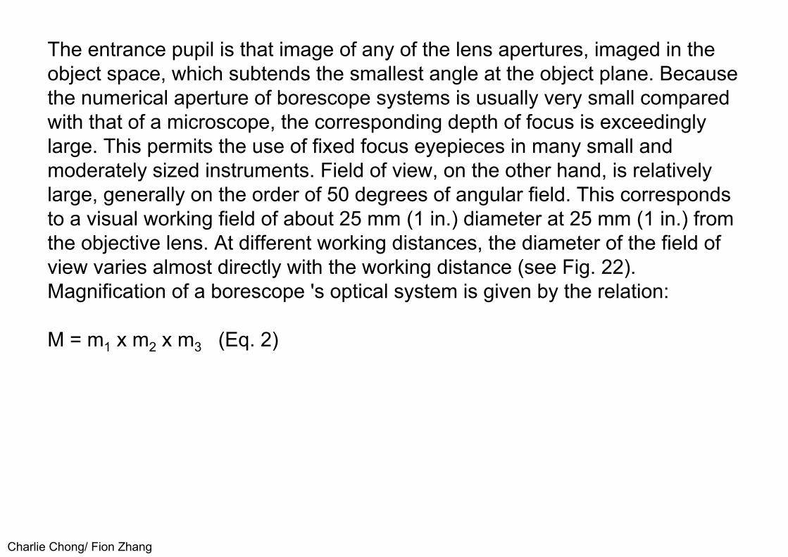
The entrance pupil is that image of any of the lens apertures, imaged in the object space, which subtends the smallest angle at the object plane. Because the numerical aperture of borescope systems is usually very small compared with that of a microscope, the corresponding depth of focus is exceedinglylarge. This permits the use of fixed focus eyepieces in many small and moderately sized instruments. Field of view, on the other hand, is relatively large, generally on the order of 50 degrees of angular field. This correspondsto a visual working field of about 25 mm (1 in.) diameter at 25 mm (1 in.) from the objective lens. At different working distances, the diameter of the field of view varies almost directly with the working distance (see Fig. 22). Magnification of a borescope 's optical system is given by the relation:
M = m1 x m2 x m3 (Eq. 2)
Charlie Chong/ Fion Zhang

where m,, m, and m, are the magnifications of the objective, middle lenses and ocular. The total magnification of borescopes varies with diameter and length but generally ranges from about 2 x to 8 x in use. Note that the linearmagnification of a given borescope changes with working distance and is about inversely proportional to the object distance. A borescope with 2 x magnification at 25 mm (1 in.) working distance therefore will magnify 4 x at 13 mm (0.5 in.) distance.
Charlie Chong/ Fion Zhang

3.6 Borescope Construction
A borescopic system usually consists of one or more borescopes having integral or attached illumination, additional sections or extensions, a battery handle, battery box or transformer power supply and extra lamps, all designed to fit in a portable case (see Fig. 25). The parts of a fixed lengthborescope for right angle vision are shown in Fig. 26. Also shown is a lamp at the objective end of the device. In this configuration, insulated wires are located between the inner and outer tubes of the borescope and serve as electrical connections between the lamp and the contacts at the ocularend. A contact ring permits rotation of the borescope through 360 degrees for scanning the object space without entangling the electrical cord. In other models, a fixed contact post is provided for attachment to a battery or a transformer, or the illumination is provided by fiber optic light guides (see Fig. 16).
Charlie Chong/ Fion Zhang

Borescopes with diameters under 37 mm (1.5 in.) are usually made in sections, with focusing eyepieces, interchangeable objectives and high power integral lamps. This kind of borescope typically consists of an eyepiece or ocular section, a 1 or 2 in (3 or 6 ft) objective section, with I, 2 or 3 m (3, 6or 9 ft) extension sections. The extensions are threaded for fitting and ring contacts are incorporated in the junctions for electrical connections. Special optics can be added to increase magnification when the object is viewed at adistance. Eyepiece extensions at right angles to the axis of the borescope can be supplied, with provision to rotate the borescope with respect to the eyepiece extension, for scanning the object field.
Charlie Chong/ Fion Zhang

FIGURE 25. Components of typical borescope system (case not shown)
Charlie Chong/ Fion Zhang
3.6.1 Right Angle Borescopes
The right angle borescope is usually furnished with the light source positioned ahead of the objective lens (see Fig. 26). The optical system provides vision at right angles to the axis of the borescope and covers a working field of about 25 mm (1 in.) diameter at 25 mm (1 in.) from the objective lens.
Applications of the right angle borescope are widespread. The instrument permits testing of inaccessible corners and internal surfaces. It is available in a wide range of lengths, in large diameters or for insertion into apertures as small as 2.3 mm (0.09 in.). It is the ideal instrument for visual tests of rifle and pistol barrels, walls of cylindrical or recessed holes and similar components.
Charlie Chong/ Fion Zhang

Another application of the right angle borescope is inspection of the internal entrance of cross holes, where it may be critical to detect and remove burrs and similar irregularities that interfere with correct service. Drilled oil leads in castings can be visually inspected, immediately following the drilling operation, for blowholes or other discontinuities that cause rejection of the component. Right angle borescopes can be equipped with fixtures to provide fast routine tests of parts in production. The device's portability allows occasional tests to be made at any point in a machining cycle
Charlie Chong/ Fion Zhang

FIGURE 26. A typical right angle borescope
Charlie Chong/ Fion Zhang

3.6.2 Forward Oblique Borescopes
The forward oblique system is a design that permits the mounting of a light source at the end of the borescope yet also allows forward and oblique vision extending to an angle of about 55 degrees from the axis of the borescope.A unique feature of this optical system is that, by rotating the borescope, the working area of the visual field is greatly enlarged.
3.6.3 Retrospective Borescope
The retrospective borescope has an integral light source mounted slightly to the rear of the objective lens. For a bore with an internal shoulder whose surfaces must be accurately tooled, the retrospective borescope provides a unique method of accurate visual inspection.
Charlie Chong/ Fion Zhang

3.6.4 Direct Vision Borescope
The direct vision instrument provides a view directly forward with a typical visual area of about 19 mm (0.75 in.) at 25 ram (1 in.) distance from the objective lens. The light carrier is removable so that the two parts can be passed successively through a small opening.
Charlie Chong/ Fion Zhang

3.6.5 Section Borescopes
Borescopes under 38 mm (1.5 in.) diameter are often made in pieces, with the objective section 1 or 2m (3 or 6 ft) in length. The additional sections are 1, 2 or 3m (3, 6 or 9 ft) long with threaded connections. These sections may he added to form borescopes with lengths up to 15m (45 ft) for diameters under 37 mm (1.5 in.). Tables 4 through 7 list the diameters and working lengths of typical borescopes. For special applications, custom made sizes and designs are available.
Charlie Chong/ Fion Zhang

TABLE 4. Specifications of right angle borescopes
Charlie Chong/ Fion Zhang

3.7 Special Purpose Borescopes
Borescopes can be built to meet many special visual testing requirements. The factors affecting the need for custom designs include: (1) the length and position of test area, (2) its distance from the entry port, (3) the diameter andlocation of the entry port and (4) inspector distance from the entry port. Environmental conditions such as temperature, pressure, water immersion, chemical vapors or ionizing radiation are important design factors. The range of special applications is partly illustrated by the examples given below
Charlie Chong/ Fion Zhang

3.7.1 Miniature Borescopes
Miniature borescopes are made in diameters as small as 1.75 mm (0.07 in.), including the light source. They are useful because they can go into small holes. Inspection of microwave guide tubing is a typical application.
3.7.2 Periscopes
A large periscopic instrument with a right angle eyepiece and a scanning prism at the objective end is shown in Fig. 27. This instrument is 125 mm (5 in.) in diameter and 9 m (27 ft) long. It is sectioned and provides for visual or photographic study of models in wind tunnels. A field of view 70 degreesin azimuth by 115 degrees in elevation is covered by this design. The cave borescope is a multiangulated, periscopic instrument used for remote observation of otherwise inaccessible areas.
Charlie Chong/ Fion Zhang

Periscopes
Charlie Chong/ Fion Zhang

3.7.3 Indexing Borescope
Butt welds in pipes or tubing 200 mm (8 in.) in diameter or larger can be visually tested with a special 90 degree indexing borescope. The instrument is inserted in extended form through a small hole drilled next to the weld seam and is then indexed to the 90 degree position by rotation of a knob at the eyepiece. The objective head is then centered within the tube for viewing the weld. A second knob at the eyepiece rotates the objective head through 360 degrees for scanning the weld seam. Another application of this instrument is for inspecting the inside surface of cathode ray tubes.
Charlie Chong/ Fion Zhang

3.7.4 Panoramic Borescopes
The panoramic borescope has a scanning mirror mounted in front of the objective lens system. Rotation of the mirror is accomplished by means of an adjusting knob at the ocular end of the instrument. This permits scanning in one plane to cover the ranges of forward oblique, right angle and retrospective vision (see Fig. 28). Another form of panoramic borescope permits rapid scanning of the internal cylindrical surfaces of tubes or pipes. This instrument has a unique objective system that simultaneously covers a cylindrical strip 30 degrees wide around the entire 360 degrees with respect to the axis of the borescope. The diameter of this instrument is 25 mm (1 in.) and the working length is 1 m (3 ft) or larger.
Charlie Chong/ Fion Zhang

TABLE 5. Specifications of section borescopes with working lengths of 1, 2 and 3 m (3, 6 and 9 ft) and extension sections of 1, 2 and 3 m (3, 6 and 9 ft)
Charlie Chong/ Fion Zhang

TABLE 6. Specifications of forward oblique borescopes
Charlie Chong/ Fion Zhang

FIGURE 27. Eyepiece end of large wind tunnel periscope
Charlie Chong/ Fion Zhang

3.7.5 Reading Borescopes
Low power reading borescopes are used in plant or laboratory setups for viewing the scales of instruments such as cathetometers at moderately remote locations. The magnification is about 3 X at 1 m (3 ft) distance.
Charlie Chong/ Fion Zhang

TABLE 7. Specifications of borescopes with separate light carriers
Charlie Chong/ Fion Zhang

FIGURE 28. Panoramic borescope: (a) comparative ranges of vision and (b) panoramic systemcomponents
Charlie Chong/ Fion Zhang
3.7.6 Photographic Adaptations
Many borescopes also include the ability to record with still photography, motion picture or video tape. For example, still pictures on 35 mm film can be taken with a borescope fitted with an adapter designed for the purpose. A telescopic system with a movable prism built into the adapter operateson the reflex principle, permitting observation of the visual field of the horescope up to the instant of photographic exposure. High intensity light sources incorporated into the borescope provide illumination for 16 mm circular pictures on 35 mm film. Motion pictures are possible with a fiber optic light source or a rod illuminator that eliminates electrical connections and the heat of a lamp from the objective end of the borescope. This is especially valuable where explosive vapors are present.
Charlie Chong/ Fion Zhang

Photography of the interiors of large power plant furnaces during operation has been done since the 1940s using a unit power periscope and camera.' The periscope extends through the furnace wall and relays the optical image to the camera. A water cooled jacket protects the optical system and the camera from the furnace's high temperatures. With this equipment, still and motion picture studies have been made of the movement of the fuel bed and the action of the powdered fuel burner in furnaces operating at full load.
Charlie Chong/ Fion Zhang

Wireless Bluetooth Borescope
Charlie Chong/ Fion Zhang
http://s.taobao.com/search?initiative_id=staobaoz_20140830&js=1&stats_click=search_radio_all%253A1&q=%C4%DA%BF%FA%BE%B5+%CE%DE%CF%DF

Charlie Chong/ Fion Zhang

Charlie Chong/ Fion Zhang