VESDA VLS Product Guide - pertronic.co.nz€¦ · VESDA VLS ProductGuide VESDAbyXtralis 4 2.1...
56
VESDA VLS Product Guide July 2016 Document: 10279_10 Part Number: 19147
Transcript of VESDA VLS Product Guide - pertronic.co.nz€¦ · VESDA VLS ProductGuide VESDAbyXtralis 4 2.1...

VESDA VLSProduct Guide
July 2016
Document: 10279_10
Part Number: 19147

VESDA by Xtralis VESDA VLS Product Guide
www.xtralis.com i
Intellectual Property and CopyrightThis document includes registered and unregistered trademarks. All trademarks displayed are the trademarks oftheir respective owners. Your use of this document does not constitute or create a licence or any other right to usethe name and/or trademark and/or label.
This document is subject to copyright owned by Xtralis AG (“Xtralis”). You agree not to copy, communicate to thepublic, adapt, distribute, transfer, sell, modify or publish any contents of this document without the express priorwritten consent of Xtralis.
DisclaimerThe contents of this document is provided on an “as is” basis. No representation or warranty (either express orimplied) is made as to the completeness, accuracy or reliability of the contents of this document. The manufacturerreserves the right to change designs or specifications without obligation and without further notice. Except asotherwise provided, all warranties, express or implied, including without limitation any implied warranties ofmerchantability and fitness for a particular purpose are expressly excluded.
General WarningThis product must only be installed, configured and used strictly in accordance with the General Terms andConditions, User Manual and product documents available from Xtralis. All proper health and safety precautionsmust be taken during the installation, commissioning and maintenance of the product. The system should not beconnected to a power source until all the components have been installed. Proper safety precautions must be takenduring tests and maintenance of the products when these are still connected to the power source. Failure to do soor tampering with the electronics inside the products can result in an electric shock causing injury or death and maycause equipment damage. Xtralis is not responsible and cannot be held accountable for any liability that may arisedue to improper use of the equipment and/or failure to take proper precautions. Only persons trained through anXtralis accredited training course can install, test and maintain the system.
LiabilityYou agree to install, configure and use the products strictly in accordance with the User Manual and productdocuments available from Xtralis.
Xtralis is not liable to you or any other person for incidental, indirect, or consequential loss, expense or damages ofany kind including without limitation, loss of business, loss of profits or loss of data arising out of your use of theproducts. Without limiting this general disclaimer the following specific warnings and disclaimers also apply:
Fitness for PurposeYou agree that you have been provided with a reasonable opportunity to appraise the products and have madeyour own independent assessment of the fitness or suitability of the products for your purpose. You acknowledgethat you have not relied on any oral or written information, representation or advice given by or on behalf of Xtralisor its representatives.
Total LiabilityTo the fullest extent permitted by law that any limitation or exclusion cannot apply, the total liability of Xtralis inrelation to the products is limited to:
i. in the case of services, the cost of having the services supplied again; orii. in the case of goods, the lowest cost of replacing the goods, acquiring equivalent goods or having the goods
repaired.
IndemnificationYou agree to fully indemnify and hold Xtralis harmless for any claim, cost, demand or damage (including legal costson a full indemnity basis) incurred or which may be incurred arising from your use of the products.
MiscellaneousIf any provision outlined above is found to be invalid or unenforceable by a court of law, such invalidity orunenforceability will not affect the remainder which will continue in full force and effect. All rights not expresslygranted are reserved.
VESDA VLS Product Guide VESDA by Xtralis
ii www.xtralis.com
ScopeThis manual is written to provide you with comprehensive knowledge of the detector.
This manual introduces you to the VESDA VLS features, technical specifications and gives an understandingof its components and their function. You will also find instructions on installing, cabling and powering up thedetector.
This manual is for anyone involved with the design, maintenance and purchasing of the VESDA system. It isassumed that anyone using this manual has knowledge and the appropriate certification from the local fire andelectrical authorities.
Document ConventionsThe following typographic conventions are used in this document:
Convention DescriptionBold Used to denote: emphasis.
Used for names of menus, menu options, toolbar buttons.
Italics Used to denote: references to other parts of this document or otherdocuments. Used for the result of an action.
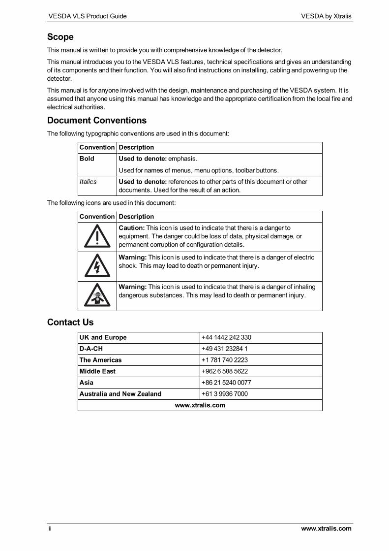
The following icons are used in this document:
Convention DescriptionCaution: This icon is used to indicate that there is a danger toequipment. The danger could be loss of data, physical damage, orpermanent corruption of configuration details.
Warning: This icon is used to indicate that there is a danger of electricshock. This may lead to death or permanent injury.
Warning: This icon is used to indicate that there is a danger of inhalingdangerous substances. This may lead to death or permanent injury.
Contact UsUK and Europe +44 1442 242 330
D-A-CH +49 431 23284 1
The Americas +1 781 740 2223
Middle East +962 6 588 5622
Asia +86 21 5240 0077
Australia and New Zealand +61 3 9936 7000
www.xtralis.com
VESDA by Xtralis VESDA VLS Product Guide
www.xtralis.com iii
Codes and Standards Information for Air Sampling Smoke DetectionWe strongly recommend that this document is read in conjunction with the appropriate local codes and standardsfor smoke detection and electrical connections. This document contains generic product information and somesections may not comply with all local codes and standards. In these cases, the local codes and standards musttake precedence. The information below was correct at time of printing but may now be out of date, check with yourlocal codes, standards and listings for the current restrictions.
FCC Compliance StatementThis equipment has been tested and found to comply with the limits for a Class B digital device, pursuant to part 15of the FCC Rules. These limits are designed to provide reasonable protection against harmful interference in aresidential installation. This equipment generates, uses and can radiate radio frequency energy and, if not installedand used in accordance with the instruction, may cause harmful interference to radio communications. However,there is no guarantee that interference will not occur in a particular installation. If this equipment does causeharmful interference to radio or television reception, the user is encouraged to try to correct the interference by oneor more of the following measures; re-orientate or relocate the receiving antenna, increase the separation betweenthe equipment and receiver, connect the equipment to a power outlet which is on a different power circuit to thereceiver or consult the dealer or an experienced radio/television technician for help.
FDAThis Xtralis product incorporates a laser device and is classified as a Class 1 laser product that complies with FDAregulations 21 CFR 1040.10. The laser is housed in a sealed detector chamber and contains no serviceable parts.The laser emits invisible light and can be hazardous if viewed with the naked eye. Under no circumstances shouldthe detector chamber be opened.
FM Hazardous Applications3611 Hazardous Approval Warning: Exposure to some chemicals may degrade the sealing of relays used on thedetector. Relays used on the detector are marked “TX2-5V”, “G6S-2-5V” or “EC2-5NU”.
VESDA detectors must not be connected or disconnected to a PC while the equipment is powered in an FMDivision 2 hazardous (classified) location (defined by FM 3611).
FM Approved ApplicationsThe product must be powered from VPS-100US-120 or VPS-100US-220 only.
ONORM F3014ONORM F3014, transport times for all tubes (including capillaries) must not exceed 60 seconds from any hole. Thismeans that the predesigned pipe networks that include capillaries cannot be used.
AS1603.8The performance of this product is dependent upon the configuration of the pipe network. Any extensions ormodifications to the pipe network may cause the product to stop working correctly. You must check that ASPIREapproves alterations before making any changes. ASPIRE is available from your VESDA ASD distributor.
AS1851.1 2005Maintenance Standards. Wherever this document and the AS1851.1 differ, AS1851.1 should be followed inpreference to this document.
VESDA VLS Product Guide VESDA by Xtralis
iv www.xtralis.com
Regional Regulatory Requirements and NoticesULFor open area protection the fire alarm threshold (signal) that initiates an evacuation procedure via the Fire AlarmPanel must not be set less sensitive than 0.625%/ft. The detector can send this signal via the Fire Alarm PanelOutput signal or the Pre-alarm output signal.
Through validation testing, Underwriters Laboratories Inc. has verified that VESDA ECO gas detectors, wheninstalled within the sample pipe network, present no significant effects on the smoke detection performance ofVESDA. The use of the ASPIRE calculation software is required to verify system design performance with alldevices included in the design.
European InstallationsThe product must use a power supply conforming to EN54: Part 4.
EN54-20The product must use a power supply conforming to EN 54-4.
The product is compliant with EN 54-20 sensitivity requirements provided the following conditions are met:
l For a Class A detector, hole sensitivity must be better than 1.5% obscuration/m and transport time less than75 seconds
l For a Class B detector, hole sensitivity must be better than 4.5% obscuration/m and transport time less than90 seconds
l For a Class C detector, hole sensitivity must be better than 10% obscuration/m and transport time less than90 seconds
The product is compliant with EN 54-20 flow monitoring requirements provided the following conditions are met:
l The minor low and minor high flow thresholds should be set at 80% and 115% respectivelyl The flow through the detector predicted by ASPIRE should be in the range 20 to 115 lpm
These limits should be verified using ASPIRE during the design of the sampling pipe network.
Additional information:l Class A detectors passed EN 54-20 approvals testing with 40 holes and 0.08% obscuration/m detectorsensitivity
l Class B detectors passed EN 54-20 approvals testing with 40 holes and 0.23% obscuration/m detectorsensitivity
l Class C detectors passed EN 54-20 approvals testing with 60 holes and 0.65% obscuration/m detectorsensitivity
Product Listingsl ULl ULCl FMl CCCl ActivFirel CEl LPCBl VdSl VNIIPOl NFl EN 54-20
Regional approvals listings and regulatory compliance vary between VESDA product models. Refer towww.xtralis.com for the latest product approvals matrix.
Document: 10279_10
Part Number: 19147
VESDA by Xtralis VESDA VLS Product Guide
www.xtralis.com i
Table of Contents1 Introduction 1
1.1 Features 1
2 Operation 32.1 The Scanning Function 42.2 VESDA VLS Configurations 62.3 VESDA VLS Components 10
3 Product Information 113.1 Product Specifications 113.2 Dimensions 133.3 Default Settings 143.4 Relays 16
4 Mounting the Detector 194.1 Securing themounting bracket 194.2 Mounting the Detector in Normal Orientation 194.3 Mounting the Detector in the Inverted Orientation 204.4 Mounting the Detector without mounting bracket 204.5 Recess mounting kit 21
5 Connecting to the Pipe Network 235.1 Inlet Pipes 235.2 Managing the Exhaust Air 24
6 Wiring Connections 256.1 Termination Card 25
7 Power Source 29
8 Backup Battery Power 318.1 Backup battery size calculation sheet 31
9 Starting Up 339.1 Installation Checklist 34
10 Preliminary Systems Check 35
11 Maintenance 3711.1 Replacing the chassis/Air Inlet PipeManifold 3811.2 Internal Wiring for the VESDA VLS 40
12 Spare Parts 43
Index 45

VESDA VLS Product Guide VESDA by Xtralis
ii www.xtralis.com
This page is intentionally left blank.
VESDA by Xtralis VESDA VLS Product Guide
www.xtralis.com 1
1 IntroductionThe VESDA VLS is an aspirating smoke detector providing very early warning of fire conditions by drawing airsamples through an air sampling pipe network. The detector chamber can detect presence of smoke at verylow concentrations. The embedded and PC software complimenting the VESDA VLS provides a wide rangeof user defined parameters and reporting capabilities. The detector easily interfaces with fire warning and firesuppression release systems, and can be easily integrated into a buildingmanagement system.
The VESDA VLS canmonitor and individually report on four sectors in the protected area.
1.1 FeaturesThe VESDA VLS features make it a versatile smoke detection product:
l Wide sensitivity range 0.005% obs/m to 20.0% obs/m (0.0016% obs/ft. to 6.24% obs/ft.)l Each detector can cover an area of up to 2,000m² (21,520 sq. ft.)l Four programmable alarm thresholds (Alert, Action, Fire 1 and Fire 2)l AutoLearn featurel Four pipe inletsl Individual pipe flow monitoringl Scans individual sectors once smoke has been detectedl Replaceable air filter cartridgel Option for invertedmountingl Recessedmounting optionl Modular to meet site specific requirementsl Modular Display Module and LCD Programmerl Programmable relays (option for 7 or 12 relays available)l High efficiency aspiratorl Programmable General Purpose Input (GPI) to invoke operational modesl PC programming andmonitoringl Multilingual displaysl Event Log for up to 18,000 events

VESDA VLS Product Guide VESDA by Xtralis
2 www.xtralis.com
This page is intentionally left blank.
VESDA by Xtralis VESDA VLS Product Guide
www.xtralis.com 3
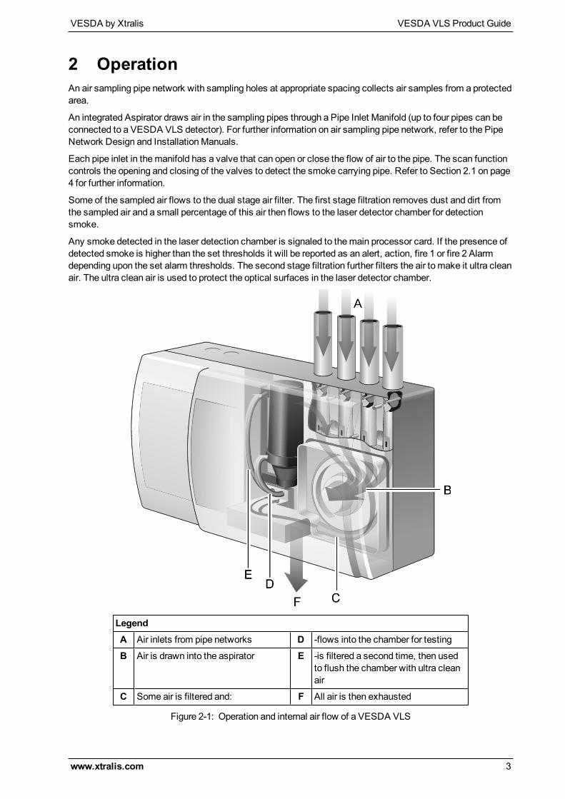
2 OperationAn air sampling pipe network with sampling holes at appropriate spacing collects air samples from a protectedarea.
An integrated Aspirator draws air in the sampling pipes through a Pipe Inlet Manifold (up to four pipes can beconnected to a VESDA VLS detector). For further information on air sampling pipe network, refer to the PipeNetwork Design and InstallationManuals.
Each pipe inlet in themanifold has a valve that can open or close the flow of air to the pipe. The scan functioncontrols the opening and closing of the valves to detect the smoke carrying pipe. Refer to Section 2.1 on page4 for further information.
Some of the sampled air flows to the dual stage air filter. The first stage filtration removes dust and dirt fromthe sampled air and a small percentage of this air then flows to the laser detector chamber for detectionsmoke.
Any smoke detected in the laser detection chamber is signaled to themain processor card. If the presence ofdetected smoke is higher than the set thresholds it will be reported as an alert, action, fire 1 or fire 2 Alarmdepending upon the set alarm thresholds. The second stage filtration further filters the air to make it ultra cleanair. The ultra clean air is used to protect the optical surfaces in the laser detector chamber.
LegendA Air inlets from pipe networks D -flows into the chamber for testing
B Air is drawn into the aspirator E -is filtered a second time, then usedto flush the chamber with ultra cleanair
C Some air is filtered and: F All air is then exhausted
Figure 2-1: Operation and internal air flow of a VESDA VLS
VESDA VLS Product Guide VESDA by Xtralis
4 www.xtralis.com
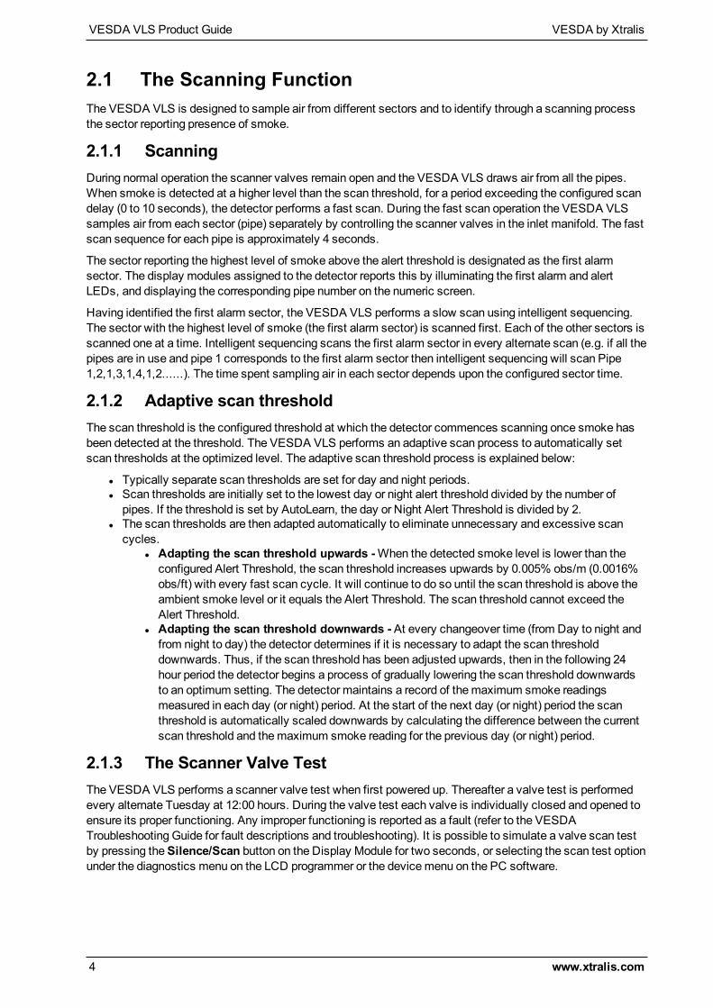
2.1 The Scanning FunctionThe VESDA VLS is designed to sample air from different sectors and to identify through a scanning processthe sector reporting presence of smoke.
2.1.1 ScanningDuring normal operation the scanner valves remain open and the VESDA VLS draws air from all the pipes.When smoke is detected at a higher level than the scan threshold, for a period exceeding the configured scandelay (0 to 10 seconds), the detector performs a fast scan. During the fast scan operation the VESDA VLSsamples air from each sector (pipe) separately by controlling the scanner valves in the inlet manifold. The fastscan sequence for each pipe is approximately 4 seconds.
The sector reporting the highest level of smoke above the alert threshold is designated as the first alarmsector. The display modules assigned to the detector reports this by illuminating the first alarm and alertLEDs, and displaying the corresponding pipe number on the numeric screen.
Having identified the first alarm sector, the VESDA VLS performs a slow scan using intelligent sequencing.The sector with the highest level of smoke (the first alarm sector) is scanned first. Each of the other sectors isscanned one at a time. Intelligent sequencing scans the first alarm sector in every alternate scan (e.g. if all thepipes are in use and pipe 1 corresponds to the first alarm sector then intelligent sequencing will scan Pipe1,2,1,3,1,4,1,2......). The time spent sampling air in each sector depends upon the configured sector time.
2.1.2 Adaptive scan thresholdThe scan threshold is the configured threshold at which the detector commences scanning once smoke hasbeen detected at the threshold. The VESDA VLS performs an adaptive scan process to automatically setscan thresholds at the optimized level. The adaptive scan threshold process is explained below:
l Typically separate scan thresholds are set for day and night periods.l Scan thresholds are initially set to the lowest day or night alert threshold divided by the number ofpipes. If the threshold is set by AutoLearn, the day or Night Alert Threshold is divided by 2.
l The scan thresholds are then adapted automatically to eliminate unnecessary and excessive scancycles.
l Adapting the scan threshold upwards -When the detected smoke level is lower than theconfigured Alert Threshold, the scan threshold increases upwards by 0.005% obs/m (0.0016%obs/ft) with every fast scan cycle. It will continue to do so until the scan threshold is above theambient smoke level or it equals the Alert Threshold. The scan threshold cannot exceed theAlert Threshold.
l Adapting the scan threshold downwards -At every changeover time (from Day to night andfrom night to day) the detector determines if it is necessary to adapt the scan thresholddownwards. Thus, if the scan threshold has been adjusted upwards, then in the following 24hour period the detector begins a process of gradually lowering the scan threshold downwardsto an optimum setting. The detector maintains a record of themaximum smoke readingsmeasured in each day (or night) period. At the start of the next day (or night) period the scanthreshold is automatically scaled downwards by calculating the difference between the currentscan threshold and themaximum smoke reading for the previous day (or night) period.
2.1.3 The Scanner Valve TestThe VESDA VLS performs a scanner valve test when first powered up. Thereafter a valve test is performedevery alternate Tuesday at 12:00 hours. During the valve test each valve is individually closed and opened toensure its proper functioning. Any improper functioning is reported as a fault (refer to the VESDATroubleshooting Guide for fault descriptions and troubleshooting). It is possible to simulate a valve scan testby pressing theSilence/Scan button on the Display Module for two seconds, or selecting the scan test optionunder the diagnostics menu on the LCD programmer or the devicemenu on the PC software.
VESDA by Xtralis VESDA VLS Product Guide
www.xtralis.com 5
2.1.4 Sector FactorBy setting appropriate sector factors it is possible to set different alarm thresholds for each of the four sectors.The detector uses the sector factor to automatically calculate the alarm thresholds appropriate for each sectorbased on the configured alarm thresholds. These aremultiplied by the sector factor to set the sector alarmthresholds.
Guidelines for setting sector factors:
l Sector factors range between 0.5 and 2.0l Wheremore sensitive protection is desired for a sector (for example a critical server room where thereare relatively more sampling holes and restricted access), set the sector factor at less than 1.0
l Where less sensitive protection is desired for a sector (for example where there is a risk that aparticular local process will generate nuisance alarms), set the sector factor at greater than 1.0
l As a general rule, the difference between all pipes should not be greater than 1Sector factors are generally optimized after a detector has been operational for a period and sufficienthistorical data has been gathered in the event log to assist the decision. However, if it is required to pre-determine the appropriate setting for sector factor the followingmethodology can be used:
l Use ASPIRE PipeModelling Software tomodel the intended pipe layoutl Determine the appropriate fire sensitivity required for each sector to achieve the desired holesensitivity in each sector
l Select an appropriate median setting for the Fire 1 threshold to be configured in the detector andcalculate the appropriate sector factor which, whenmultiplied by the configured Fire 1 threshold, willgive the desired fire sensitivity for each pipe
l Record the desired Fire 1 threshold setting and sector factor setting for configuration into the detectorat commissioning.
VESDA VLS Product Guide VESDA by Xtralis
6 www.xtralis.com
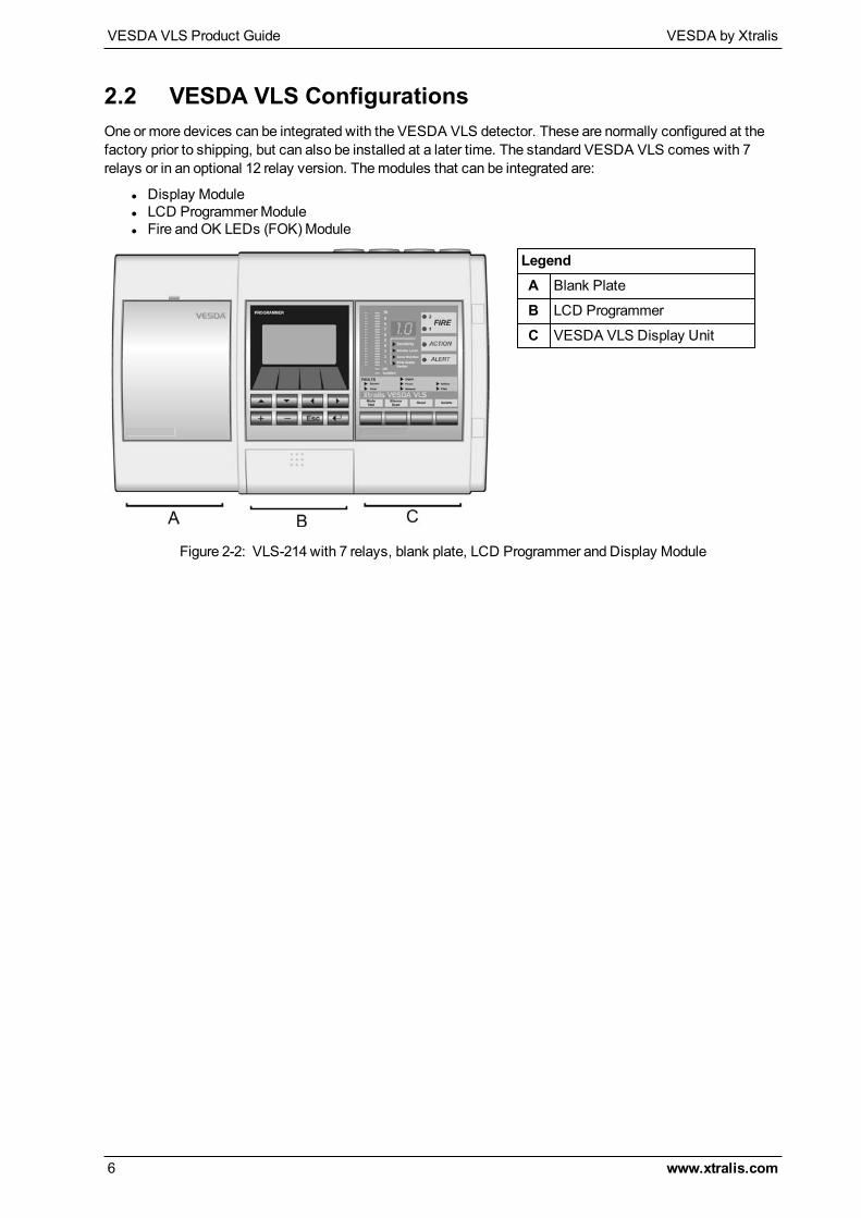
2.2 VESDA VLS ConfigurationsOne ormore devices can be integrated with the VESDA VLS detector. These are normally configured at thefactory prior to shipping, but can also be installed at a later time. The standard VESDA VLS comes with 7relays or in an optional 12 relay version. Themodules that can be integrated are:
l Display Modulel LCD ProgrammerModulel Fire andOK LEDs (FOK)Module
LegendA Blank Plate
B LCD Programmer
C VESDA VLS Display Unit
Figure 2-2: VLS-214 with 7 relays, blank plate, LCD Programmer and Display Module
VESDA by Xtralis VESDA VLS Product Guide
www.xtralis.com 7
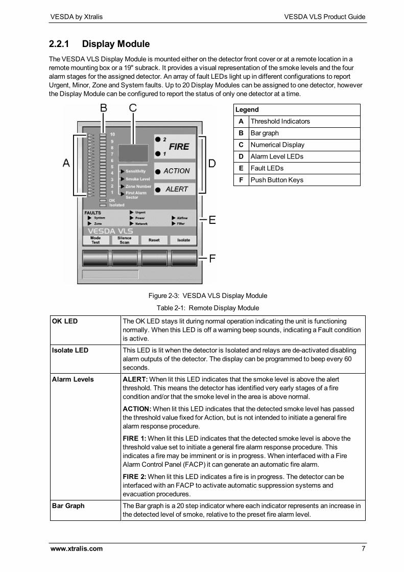
2.2.1 Display ModuleThe VESDA VLS Display Module is mounted either on the detector front cover or at a remote location in aremotemounting box or a 19" subrack. It provides a visual representation of the smoke levels and the fouralarm stages for the assigned detector. An array of fault LEDs light up in different configurations to reportUrgent, Minor, Zone and System faults. Up to 20 Display Modules can be assigned to one detector, howeverthe Display Module can be configured to report the status of only one detector at a time.
LegendA Threshold Indicators
B Bar graph
C Numerical Display
D Alarm Level LEDs
E Fault LEDs
F Push Button Keys
Figure 2-3: VESDA VLS Display Module
OK LED TheOK LED stays lit during normal operation indicating the unit is functioningnormally. When this LED is off a warning beep sounds, indicating a Fault conditionis active.
Isolate LED This LED is lit when the detector is Isolated and relays are de-activated disablingalarm outputs of the detector. The display can be programmed to beep every 60seconds.
Alarm Levels ALERT:When lit this LED indicates that the smoke level is above the alertthreshold. This means the detector has identified very early stages of a firecondition and/or that the smoke level in the area is above normal.
ACTION:When lit this LED indicates that the detected smoke level has passedthe threshold value fixed for Action, but is not intended to initiate a general firealarm response procedure.
FIRE 1:When lit this LED indicates that the detected smoke level is above thethreshold value set to initiate a general fire alarm response procedure. Thisindicates a fire may be imminent or is in progress. When interfaced with a FireAlarm Control Panel (FACP) it can generate an automatic fire alarm.
FIRE 2:When lit this LED indicates a fire is in progress. The detector can beinterfaced with an FACP to activate automatic suppression systems andevacuation procedures.
Bar Graph The Bar graph is a 20 step indicator where each indicator represents an increase inthe detected level of smoke, relative to the preset fire alarm level.
Table 2-1: Remote Display Module
VESDA VLS Product Guide VESDA by Xtralis
8 www.xtralis.com
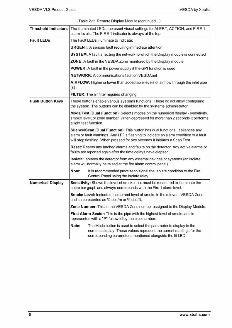
Threshold Indicators The illuminated LEDs represent visual settings for ALERT, ACTION, and FIRE 1alarm levels. The FIRE 1 indicator is always at the top.
Fault LEDs The Fault LEDs illuminate to indicate:
URGENT:A serious fault requiring immediate attention
SYSTEM:A fault affecting the network to which the Display module is connected
ZONE:A fault in the VESDA Zonemonitored by the Display module
POWER:A fault in the power supply if the GPI function is used
NETWORK:A communications fault on VESDAnet
AIRFLOW:Higher or lower than acceptable levels of air flow through the inlet pipe(s)
FILTER: The air filter requires changingPush Button Keys These buttons enable various systems functions. These do not allow configuring
the system. The buttons can be disabled by the systems administrator.
Mode/Test (Dual Function):Selects modes on the numerical display - sensitivity,smoke level, or zone number. When depressed for more than 2 seconds it performsa light test function.
Silence/Scan (Dual Function): This button has dual functions. It silences anyalarm or fault warnings. Any LEDs flashing to indicate an alarm condition or a faultwill stop flashing. When pressed for two seconds it initiates a Scan Test.
Reset:Resets any latched alarms and faults on the detector. Any active alarms orfaults are reported again after the time delays have elapsed.
Isolate: Isolates the detector from any external devices or systems (an isolatealarm will normally be raised at the fire alarm control panel).
Note: It is recommended practise to signal the Isolate condition to the FireControl Panel using the Isolate relay.
Numerical Display Sensitivity:Shows the level of smoke that must bemeasured to illuminate theentire bar graph and always corresponds with the Fire 1 alarm level.
Smoke Level: Indicates the current level of smoke in the relevant VESDA Zoneand is represented as % obs/m or% obs/ft.
Zone Number: This is the VESDA Zone number assigned to the Display Module.
First Alarm Sector: This is the pipe with the highest level of smoke and isrepresented with a "P" followed by the pipe number.
Note: TheMode button is used to select the parameter to display in thenumeric display. These values represent the current readings for thecorresponding parameters mentioned alongside the lit LED.
Table 2-1: Remote Display Module (continued...)
VESDA by Xtralis VESDA VLS Product Guide
www.xtralis.com 9
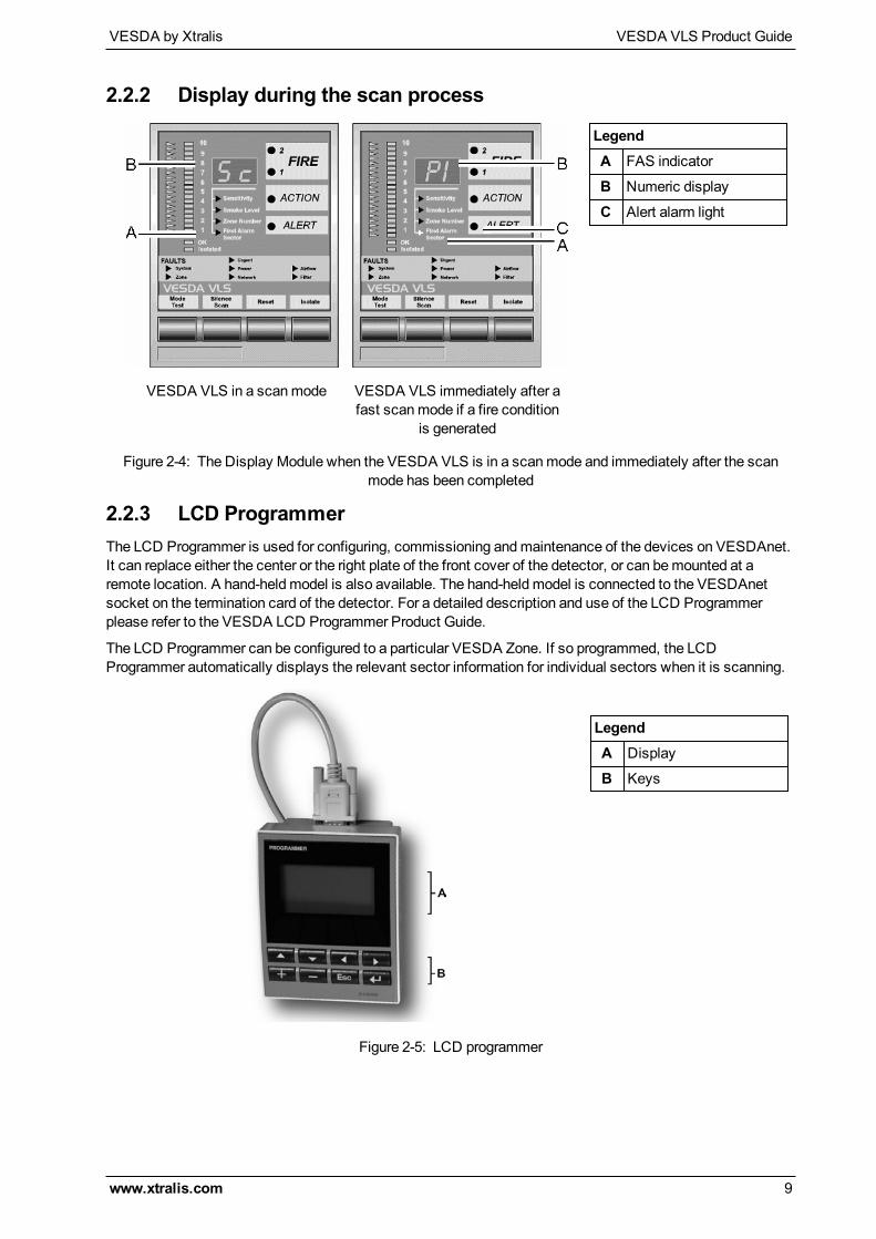
2.2.2 Display during the scan process
LegendA FAS indicator
B Numeric display
C Alert alarm light
VESDA VLS in a scanmode VESDA VLS immediately after afast scanmode if a fire condition
is generated
Figure 2-4: The Display Module when the VESDA VLS is in a scanmode and immediately after the scanmode has been completed
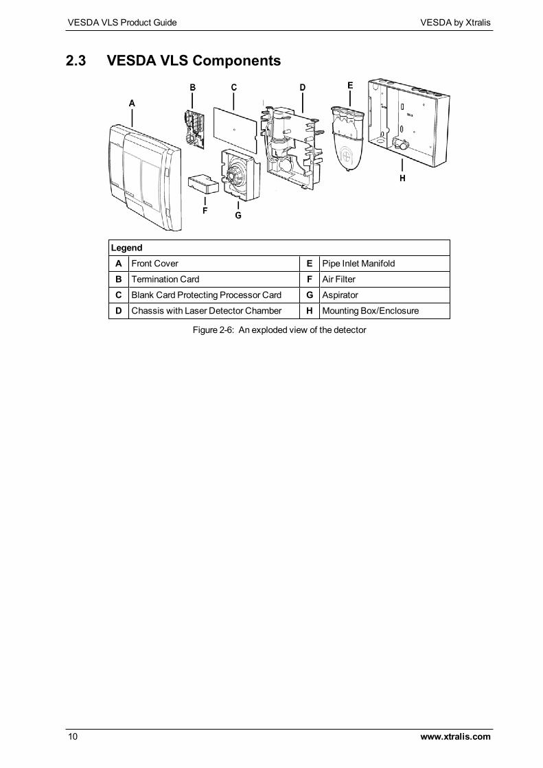
2.2.3 LCD ProgrammerThe LCD Programmer is used for configuring, commissioning andmaintenance of the devices on VESDAnet.It can replace either the center or the right plate of the front cover of the detector, or can bemounted at aremote location. A hand-heldmodel is also available. The hand-heldmodel is connected to the VESDAnetsocket on the termination card of the detector. For a detailed description and use of the LCD Programmerplease refer to the VESDA LCD Programmer Product Guide.
The LCD Programmer can be configured to a particular VESDA Zone. If so programmed, the LCDProgrammer automatically displays the relevant sector information for individual sectors when it is scanning.
LegendA Display
B Keys
Figure 2-5: LCD programmer
VESDA VLS Product Guide VESDA by Xtralis
10 www.xtralis.com
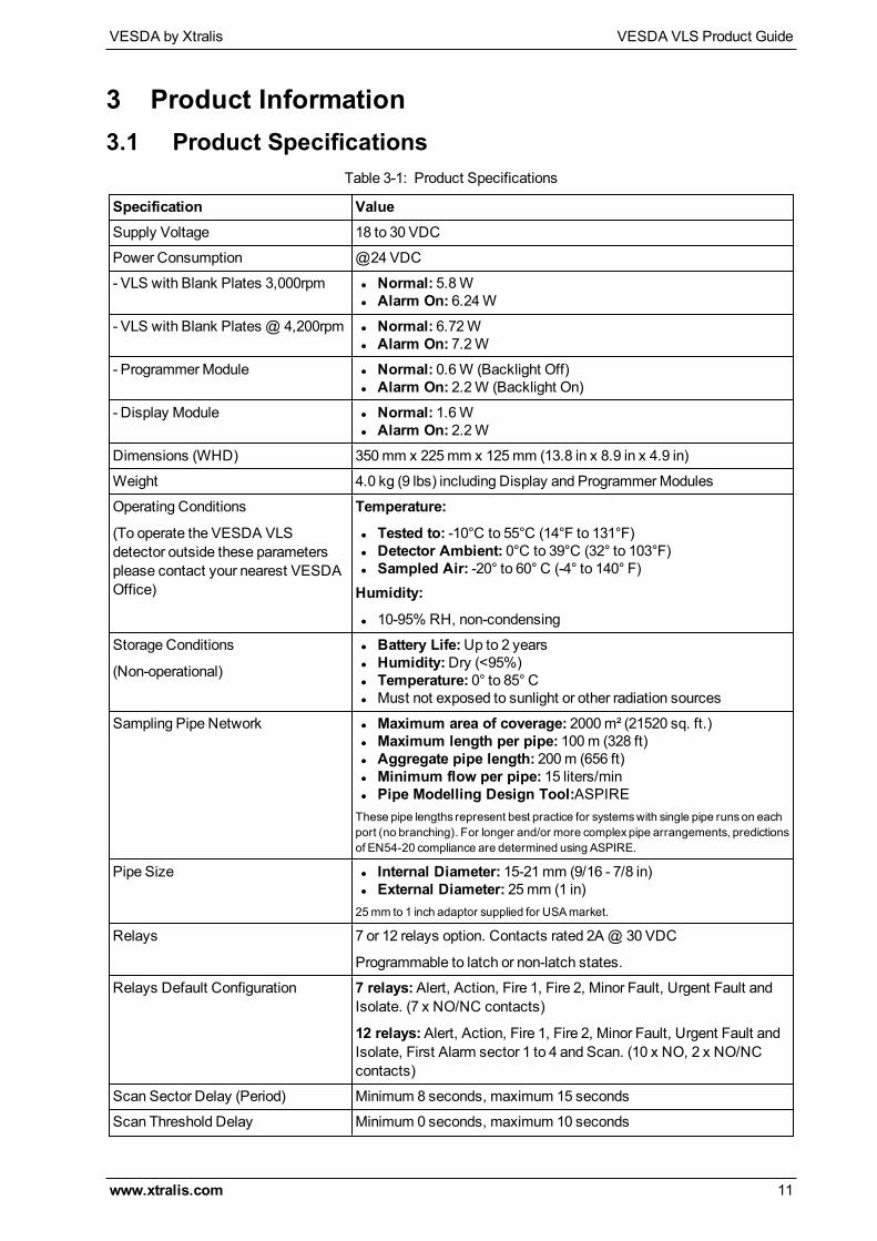
2.3 VESDA VLS Components
LegendA Front Cover E Pipe Inlet Manifold
B Termination Card F Air Filter
C Blank Card Protecting Processor Card G Aspirator
D Chassis with Laser Detector Chamber H Mounting Box/Enclosure
Figure 2-6: An exploded view of the detector
VESDA by Xtralis VESDA VLS Product Guide
www.xtralis.com 11
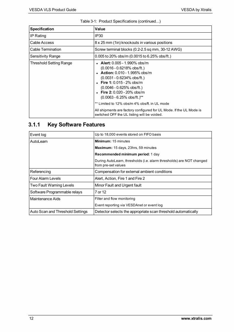
3 Product Information3.1 Product Specifications
Specification ValueSupply Voltage 18 to 30 VDC
Power Consumption @24 VDC
- VLS with Blank Plates 3,000rpm l Normal: 5.8Wl Alarm On: 6.24W
- VLS with Blank Plates @ 4,200rpm l Normal: 6.72Wl Alarm On: 7.2W
- ProgrammerModule l Normal: 0.6W (Backlight Off)l Alarm On: 2.2W (Backlight On)
- Display Module l Normal: 1.6Wl Alarm On: 2.2W
Dimensions (WHD) 350mm x 225mm x 125mm (13.8 in x 8.9 in x 4.9 in)
Weight 4.0 kg (9 lbs) including Display and ProgrammerModules
Operating Conditions
(To operate the VESDA VLSdetector outside these parametersplease contact your nearest VESDAOffice)
Temperature:
l Tested to: -10°C to 55°C (14°F to 131°F)l Detector Ambient: 0°C to 39°C (32° to 103°F)l Sampled Air: -20° to 60° C (-4° to 140° F)Humidity:
l 10-95% RH, non-condensing
Storage Conditions
(Non-operational)
l Battery Life:Up to 2 yearsl Humidity:Dry (<95%)l Temperature: 0° to 85° Cl Must not exposed to sunlight or other radiation sources
Sampling Pipe Network l Maximum area of coverage: 2000m² (21520 sq. ft.)l Maximum length per pipe: 100m (328 ft)l Aggregate pipe length: 200m (656 ft)l Minimum flow per pipe: 15 liters/minl Pipe Modelling Design Tool:ASPIREThese pipe lengths represent best practice for systemswith single pipe runson eachport (no branching). For longer and/or more complexpipe arrangements, predictionsof EN54-20 compliance are determined using ASPIRE.
Pipe Size l Internal Diameter: 15-21mm (9/16 - 7/8 in)l External Diameter: 25mm (1 in)25mm to 1 inch adaptor supplied for USAmarket.
Relays 7 or 12 relays option. Contacts rated 2A@ 30 VDC
Programmable to latch or non-latch states.
Relays Default Configuration 7 relays:Alert, Action, Fire 1, Fire 2, Minor Fault, Urgent Fault andIsolate. (7 x NO/NC contacts)
12 relays:Alert, Action, Fire 1, Fire 2, Minor Fault, Urgent Fault andIsolate, First Alarm sector 1 to 4 and Scan. (10 x NO, 2 x NO/NCcontacts)
Scan Sector Delay (Period) Minimum 8 seconds, maximum 15 seconds
Scan Threshold Delay Minimum 0 seconds, maximum 10 seconds
Table 3-1: Product Specifications
VESDA VLS Product Guide VESDA by Xtralis
12 www.xtralis.com
Specification ValueIP Rating IP30
Cable Access 8 x 25mm (1in) knockouts in various positions
Cable Termination Screw terminal blocks (0.2-2.5 sqmm, 30-12 AWG)
Sensitivity Range 0.005 to 20% obs/m (0.0015 to 6.25% obs/ft.)
Threshold Setting Range l Alert: 0.005 - 1.990% obs/m(0.0016 - 0.6218% obs/ft.)
l Action: 0.010 - 1.995% obs/m(0.0031 - 0.6234% obs/ft.)
l Fire 1: 0.015 - 2% obs/m(0.0046 - 0.625% obs/ft.)
l Fire 2: 0.020 - 20% obs/m(0.0063 - 6.25% obs/ft.)**
** Limited to 12% obs/m 4% obs/ft. in UL mode
All shipments are factory configured for UL Mode. If the UL Mode isswitched OFF the UL listing will be voided.
Table 3-1: Product Specifications (continued...)
3.1.1 Key Software FeaturesEvent log Up to 18,000 events stored on FIFO basis
AutoLearn Minimum: 15 minutes
Maximum: 15 days, 23hrs, 59 minutes
Recommendedminimum period: 1 day
During AutoLearn, thresholds (i.e. alarm thresholds) are NOT changedfrom pre-set values
Referencing Compensation for external ambient conditions
Four Alarm Levels Alert, Action, Fire 1 and Fire 2
Two Fault Warning Levels Minor Fault and Urgent fault
Software Programmable relays 7 or 12
Maintenance Aids Filter and flow monitoring
Event reporting via VESDAnet or event log
Auto Scan and Threshold Settings Detector selects the appropriate scan threshold automatically
VESDA by Xtralis VESDA VLS Product Guide
www.xtralis.com 13
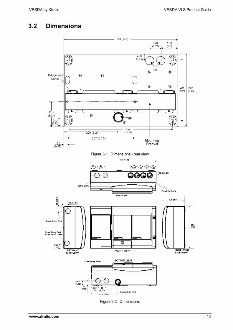
3.2 Dimensions
Figure 3-1: Dimensions - rear view
Figure 3-2: Dimensions
VESDA VLS Product Guide VESDA by Xtralis
14 www.xtralis.com
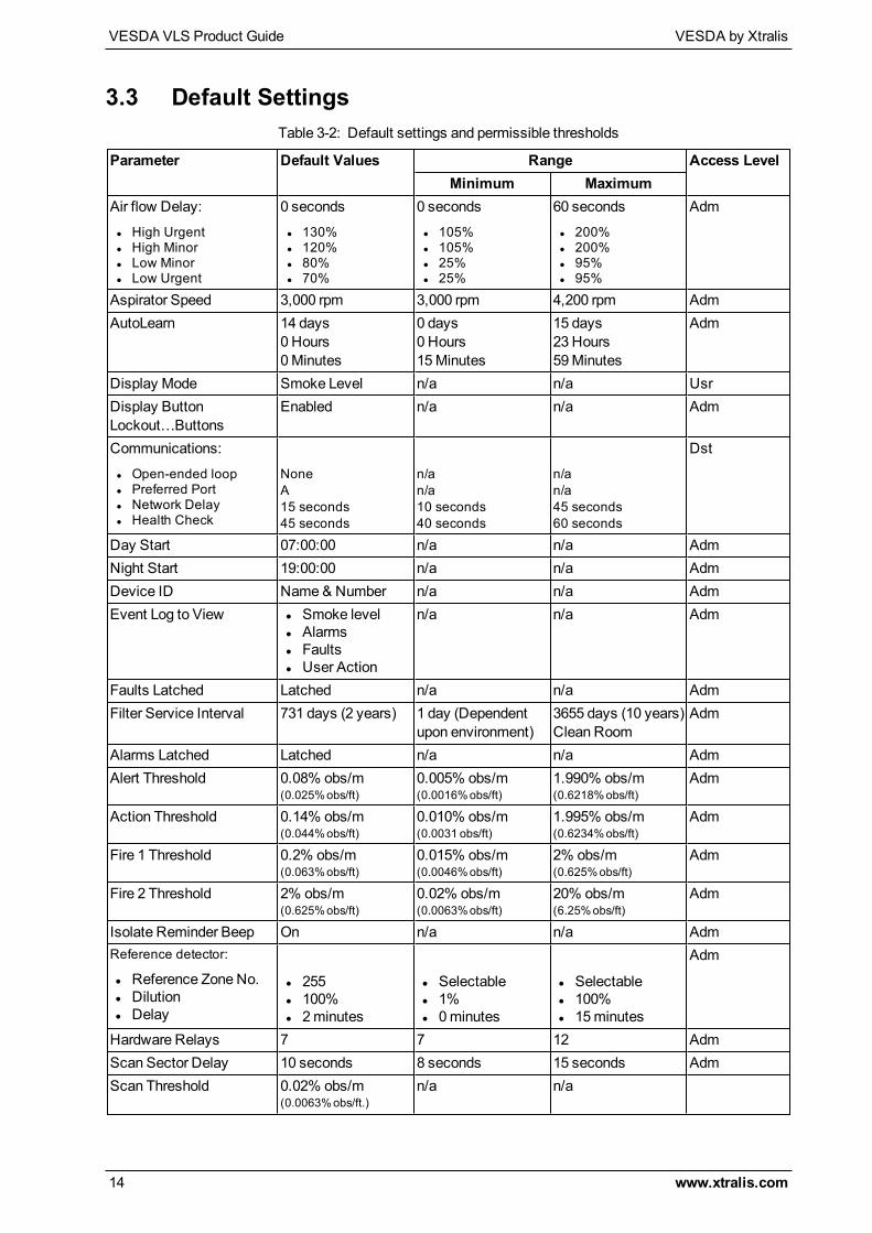
3.3 Default Settings
Parameter Default Values Range Access LevelMinimum Maximum
Air flow Delay:
l High Urgentl High Minorl Low Minorl Low Urgent
0 seconds
l 130%l 120%l 80%l 70%
0 seconds
l 105%l 105%l 25%l 25%
60 seconds
l 200%l 200%l 95%l 95%
Adm
Aspirator Speed 3,000 rpm 3,000 rpm 4,200 rpm AdmAutoLearn 14 days
0 Hours0Minutes
0 days0 Hours15Minutes
15 days23 Hours59Minutes
Adm
Display Mode Smoke Level n/a n/a UsrDisplay ButtonLockout…Buttons
Enabled n/a n/a Adm
Communications:
l Open-ended loopl Preferred Portl Network Delayl Health Check
NoneA15 seconds45 seconds
n/an/a10 seconds40 seconds
n/an/a45 seconds60 seconds
Dst
Day Start 07:00:00 n/a n/a AdmNight Start 19:00:00 n/a n/a AdmDevice ID Name& Number n/a n/a AdmEvent Log to View l Smoke level
l Alarmsl Faultsl User Action
n/a n/a Adm
Faults Latched Latched n/a n/a AdmFilter Service Interval 731 days (2 years) 1 day (Dependent
upon environment)3655 days (10 years)Clean Room
Adm
Alarms Latched Latched n/a n/a AdmAlert Threshold 0.08% obs/m
(0.025%obs/ft)0.005% obs/m(0.0016%obs/ft)
1.990% obs/m(0.6218%obs/ft)
Adm
Action Threshold 0.14% obs/m(0.044%obs/ft)
0.010% obs/m(0.0031 obs/ft)
1.995% obs/m(0.6234%obs/ft)
Adm
Fire 1 Threshold 0.2% obs/m(0.063%obs/ft)
0.015% obs/m(0.0046%obs/ft)
2% obs/m(0.625%obs/ft)
Adm
Fire 2 Threshold 2% obs/m(0.625%obs/ft)
0.02% obs/m(0.0063%obs/ft)
20% obs/m(6.25%obs/ft)
Adm
Isolate Reminder Beep On n/a n/a AdmReference detector:
l Reference Zone No.l Dilutionl Delay
l 255l 100%l 2minutes
l Selectablel 1%l 0minutes
l Selectablel 100%l 15minutes
Adm
Hardware Relays 7 7 12 AdmScan Sector Delay 10 seconds 8 seconds 15 seconds AdmScan Threshold 0.02% obs/m
(0.0063%obs/ft.)n/a n/a
Table 3-2: Default settings and permissible thresholds
VESDA by Xtralis VESDA VLS Product Guide
www.xtralis.com 15
Parameter Default Values Range Access LevelMinimum Maximum
Scan Threshold Delay 3 seconds 0 seconds 10 seconds AdmSmoke Change...Change By
0.02% obs/m(0.0063%obs/ft.)
0.005% obs/m(0.0016%obs/ft.)
1.990% obs/m(0.6218%obs/ft.)
Adm
Smoke Change...Minimum Interval
2 seconds 2 seconds 10 seconds Adm
ULVersion On Selectable Selectable AdmUnits SI Selectable Selectable AdmWeekend Saturday and
SundaySelectable Selectable Adm
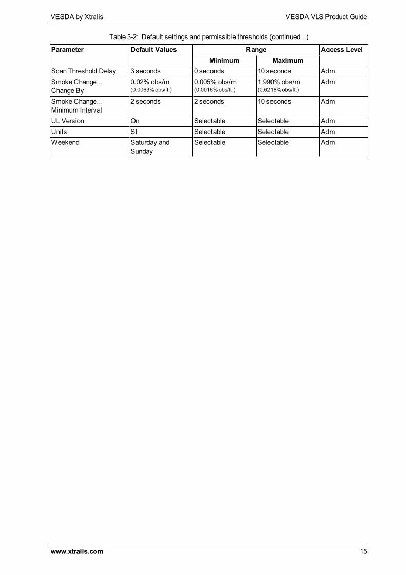
Table 3-2: Default settings and permissible thresholds (continued...)
VESDA VLS Product Guide VESDA by Xtralis
16 www.xtralis.com
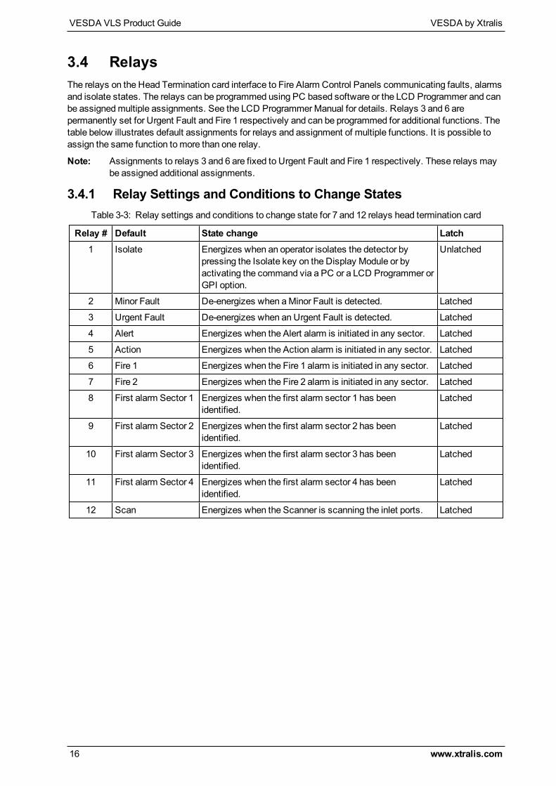
3.4 RelaysThe relays on the Head Termination card interface to Fire Alarm Control Panels communicating faults, alarmsand isolate states. The relays can be programmed using PC based software or the LCD Programmer and canbe assignedmultiple assignments. See the LCD ProgrammerManual for details. Relays 3 and 6 arepermanently set for Urgent Fault and Fire 1 respectively and can be programmed for additional functions. Thetable below illustrates default assignments for relays and assignment of multiple functions. It is possible toassign the same function tomore than one relay.
Note: Assignments to relays 3 and 6 are fixed to Urgent Fault and Fire 1 respectively. These relays maybe assigned additional assignments.
3.4.1 Relay Settings and Conditions to Change States
Relay # Default State change Latch1 Isolate Energizes when an operator isolates the detector by
pressing the Isolate key on the Display Module or byactivating the command via a PC or a LCD Programmer orGPI option.
Unlatched
2 Minor Fault De-energizes when aMinor Fault is detected. Latched
3 Urgent Fault De-energizes when an Urgent Fault is detected. Latched
4 Alert Energizes when the Alert alarm is initiated in any sector. Latched
5 Action Energizes when the Action alarm is initiated in any sector. Latched
6 Fire 1 Energizes when the Fire 1 alarm is initiated in any sector. Latched
7 Fire 2 Energizes when the Fire 2 alarm is initiated in any sector. Latched
8 First alarm Sector 1 Energizes when the first alarm sector 1 has beenidentified.
Latched
9 First alarm Sector 2 Energizes when the first alarm sector 2 has beenidentified.
Latched
10 First alarm Sector 3 Energizes when the first alarm sector 3 has beenidentified.
Latched
11 First alarm Sector 4 Energizes when the first alarm sector 4 has beenidentified.
Latched
12 Scan Energizes when the Scanner is scanning the inlet ports. Latched
Table 3-3: Relay settings and conditions to change state for 7 and 12 relays head termination card
VESDA by Xtralis VESDA VLS Product Guide
www.xtralis.com 17
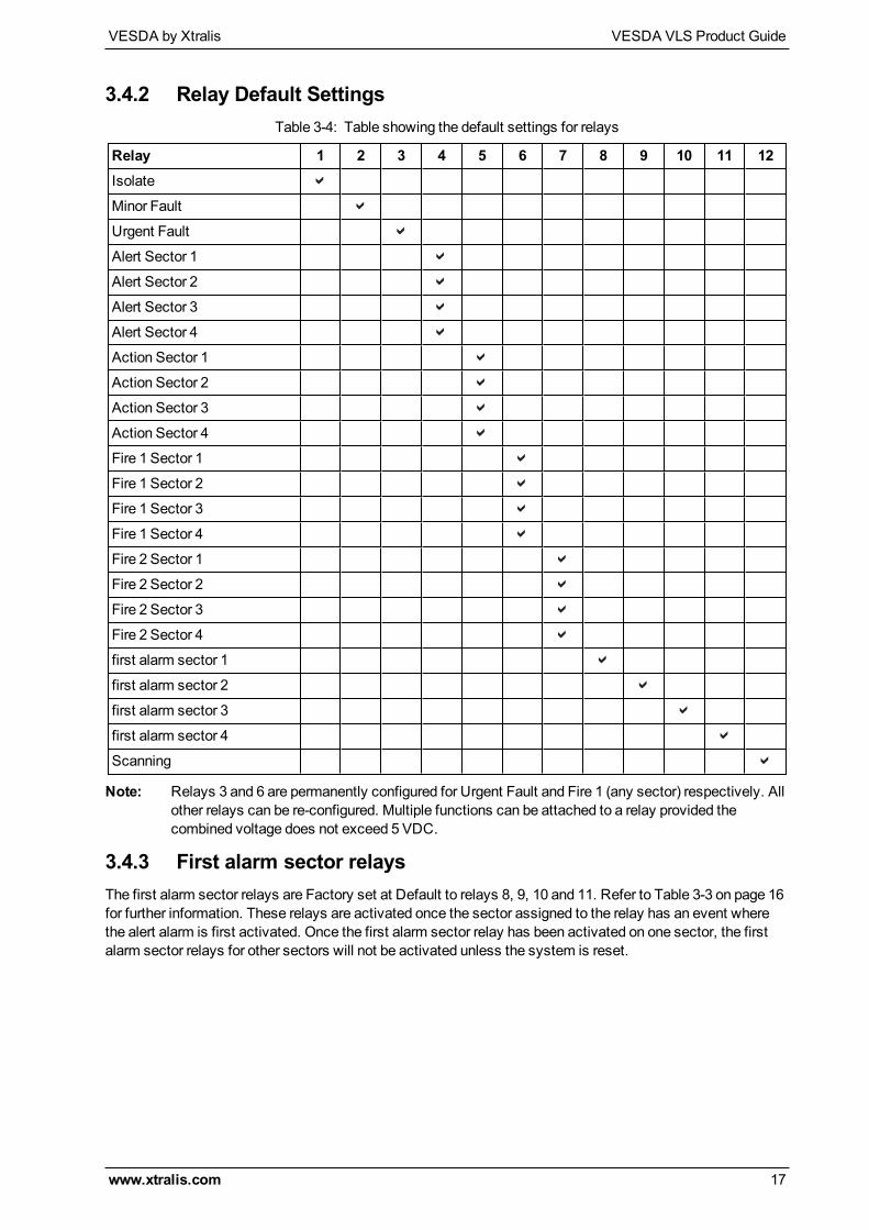
3.4.2 Relay Default Settings
Relay 1 2 3 4 5 6 7 8 9 10 11 12Isolate
Minor Fault
Urgent Fault
Alert Sector 1
Alert Sector 2
Alert Sector 3
Alert Sector 4
Action Sector 1
Action Sector 2
Action Sector 3
Action Sector 4
Fire 1 Sector 1
Fire 1 Sector 2
Fire 1 Sector 3
Fire 1 Sector 4
Fire 2 Sector 1
Fire 2 Sector 2
Fire 2 Sector 3
Fire 2 Sector 4
first alarm sector 1
first alarm sector 2
first alarm sector 3
first alarm sector 4
Scanning
Table 3-4: Table showing the default settings for relays
Note: Relays 3 and 6 are permanently configured for Urgent Fault and Fire 1 (any sector) respectively. Allother relays can be re-configured. Multiple functions can be attached to a relay provided thecombined voltage does not exceed 5 VDC.
3.4.3 First alarm sector relaysThe first alarm sector relays are Factory set at Default to relays 8, 9, 10 and 11. Refer to Table 3-3 on page 16for further information. These relays are activated once the sector assigned to the relay has an event wherethe alert alarm is first activated. Once the first alarm sector relay has been activated on one sector, the firstalarm sector relays for other sectors will not be activated unless the system is reset.
VESDA VLS Product Guide VESDA by Xtralis
18 www.xtralis.com
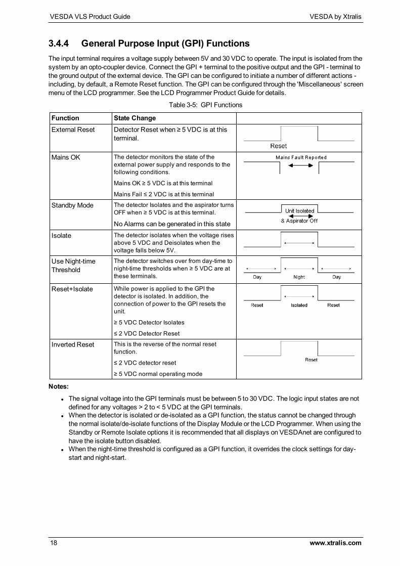
3.4.4 General Purpose Input (GPI) FunctionsThe input terminal requires a voltage supply between 5V and 30 VDC to operate. The input is isolated from thesystem by an opto-coupler device. Connect the GPI + terminal to the positive output and the GPI - terminal tothe ground output of the external device. TheGPI can be configured to initiate a number of different actions -including, by default, a Remote Reset function. TheGPI can be configured through the 'Miscellaneous' screenmenu of the LCD programmer. See the LCD Programmer Product Guide for details.
Function State ChangeExternal Reset Detector Reset when ≥ 5 VDC is at this
terminal.
Mains OK The detector monitors the state of theexternal power supply and responds to thefollowing conditions.
Mains OK ≥ 5 VDC is at this terminal
Mains Fail ≤ 2 VDC is at this terminal
Standby Mode The detector Isolates and the aspirator turnsOFF when ≥ 5 VDC is at this terminal.
NoAlarms can be generated in this state
Isolate The detector isolates when the voltage risesabove 5 VDC and Deisolates when thevoltage falls below 5V.
UseNight-timeThreshold
The detector switches over from day-time tonight-time thresholds when ≥ 5 VDC are atthese terminals.
Reset+Isolate While power is applied to the GPI thedetector is isolated. In addition, theconnection of power to the GPI resets theunit.
≥ 5 VDC Detector Isolates
≤ 2 VDC Detector Reset
Inverted Reset This is the reverse of the normal resetfunction.
≤ 2 VDC detector reset
≥ 5 VDC normal operating mode
Table 3-5: GPI Functions
Notes:
l The signal voltage into the GPI terminals must be between 5 to 30 VDC. The logic input states are notdefined for any voltages > 2 to < 5 VDC at the GPI terminals.
l When the detector is isolated or de-isolated as aGPI function, the status cannot be changed throughthe normal isolate/de-isolate functions of the Display Module or the LCD Programmer. When using theStandby or Remote Isolate options it is recommended that all displays on VESDAnet are configured tohave the isolate button disabled.
l When the night-time threshold is configured as aGPI function, it overrides the clock settings for day-start and night-start.
VESDA by Xtralis VESDA VLS Product Guide
www.xtralis.com 19
4 Mounting the DetectorThe VESDA VLS can bemounted onto the wall or on any suitable secure surface using themounting bracket.It is strongly recommended that the detector is mounted on to themounting bracket included with thepackaging. Determine the cable entry ports and the air exhaust port beforemounting the detector.Consideration should also be given to the positioning of the pipe inlet ports in relation to the existing pipenetwork.
Caution: Press out the relevant knockouts, taking care not to damage the relays and terminals on thetermination card.
Attention : Retirez les bouchons défonçables en faisant attention de ne pas endommager les relais et lesbornes sur la carte de terminaison.
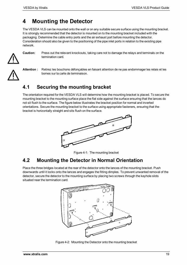
4.1 Securing the mounting bracketThe orientation required for the VESDA VLS will determine how themounting bracket is placed. To secure themounting bracket to themounting surface place the flat side against the surface ensuring that the lances donot sit flush to the surface. The figure below illustrates the bracket position for normal and invertedorientations. Secure themounting bracket to the surface using appropriate fasteners, ensuring that thebracket is horizontally straight and sits flush on the surface.
Figure 4-1: Themounting bracket
4.2 Mounting the Detector in Normal OrientationPlace the three bridges located at the rear of the detector onto the lances of themounting bracket. Pushdownwards until it locks onto the lances and engages the fitting dimples. To prevent unwanted removal of thedetector, secure the detector to themounting surface by placing two screws through the keyhole slotssituated near the termination card.
Figure 4-2: Mounting the Detector onto themounting bracket
VESDA VLS Product Guide VESDA by Xtralis
20 www.xtralis.com
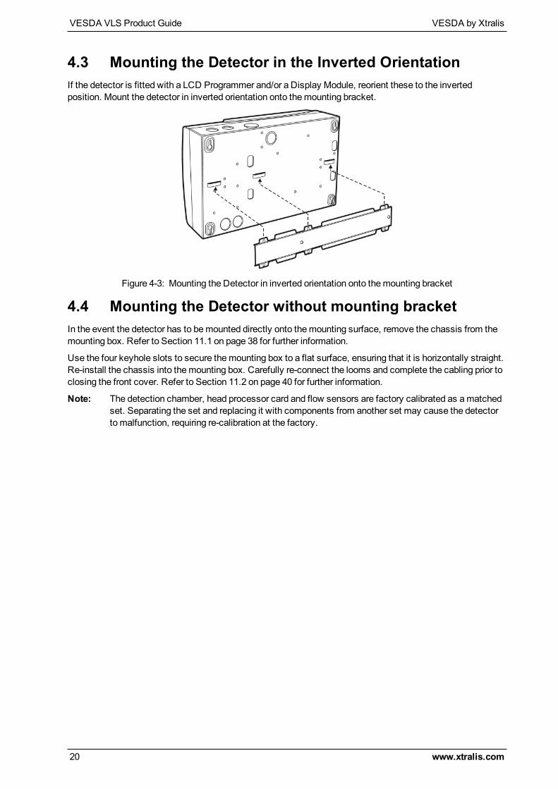
4.3 Mounting the Detector in the Inverted OrientationIf the detector is fitted with a LCD Programmer and/or a Display Module, reorient these to the invertedposition. Mount the detector in inverted orientation onto themounting bracket.
Figure 4-3: Mounting the Detector in inverted orientation onto themounting bracket
4.4 Mounting the Detector without mounting bracketIn the event the detector has to bemounted directly onto themounting surface, remove the chassis from themounting box. Refer to Section 11.1 on page 38 for further information.
Use the four keyhole slots to secure themounting box to a flat surface, ensuring that it is horizontally straight.Re-install the chassis into themounting box. Carefully re-connect the looms and complete the cabling prior toclosing the front cover. Refer to Section 11.2 on page 40 for further information.
Note: The detection chamber, head processor card and flow sensors are factory calibrated as amatchedset. Separating the set and replacing it with components from another set may cause the detectorto malfunction, requiring re-calibration at the factory.
VESDA by Xtralis VESDA VLS Product Guide
www.xtralis.com 21
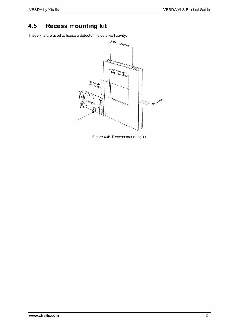
4.5 Recess mounting kitThese kits are used to house a detector inside a wall cavity.
Figure 4-4: Recess mounting kit

VESDA VLS Product Guide VESDA by Xtralis
22 www.xtralis.com
This page is intentionally left blank.

VESDA by Xtralis VESDA VLS Product Guide
www.xtralis.com 23
5 Connecting to the Pipe Network5.1 Inlet PipesThe inlets in the pipe inlet manifold are designed to receive a standard pipe of 25mm (1 in) OD. A 25mm to1.050 inches adaptor to fit the pipe inlet manifold is included for all shipments to USA.
Figure 5-1: Pipe Adaptor
The design of the air inlet ports allow insertion of the sampling pipe to a depth of 15mm. (0.60 in). Thisprevents the sampling pipes from damaging the flow sensors. While connecting the detector to the pipenetwork:
l Ensure aminimum length of 500mm (19.7 in) of straight pipe before terminating the pipes at the air inletports of the detector.
l Square off and de-burr the end of the sampling air pipes, ensuring the pipes are free from debris.l Determine the Air Inlet Ports to be used. Refer to Table 5-1 below for details.l Remove the plugs from only those Air Inlet Ports intended for use.l Insert the pipes into the pipe inlet(s) ensuring a firm fit.
DONOT glue the inlet pipes to the pipe inlet manifold. When configuring the detector ensure that the correctpipes in use are selected.:
No. of Pipes Preferred Pipe Inlet Port to usePipe 1 Pipe 2 Pipe 3 Pipe 4
1
2
3
4
Table 5-1: Preferable use of pipe inlet ports
Figure 5-2: Pipe inlet port numbering
VESDA VLS Product Guide VESDA by Xtralis
24 www.xtralis.com
5.2 Managing the Exhaust AirTo exhaust air from the detector, use the exhaust ports at the rear or at the bottom of the headmounting box.Remove the appropriate exhaust port plugs and if required, connect an outlet pipe to the exhaust manifold. Inthe event the side port is used as an air exhaust port, press out the knockout hole. Remove the plug on theexhaust manifold, located at the divider of the chassis and the termination card. Run a 25mm (1 inch) pipethrough the side port and insert into the exhaust manifold, ensuring it is a tight fit.
Notes:
l DONOT glue this pipe to the exhaust manifold.l Some applications may require the air exhausted from the detector to be returned to the sampling area.
VESDA by Xtralis VESDA VLS Product Guide
www.xtralis.com 25
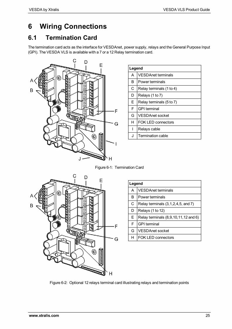
6 Wiring Connections6.1 Termination CardThe termination card acts as the interface for VESDAnet, power supply, relays and theGeneral Purpose Input(GPI). The VESDA VLS is available with a 7 or a 12 Relay termination card.
LegendA VESDAnet terminals
B Power terminals
C Relay terminals (1 to 4)
D Relays (1 to 7)
E Relay terminals (5 to 7)
F GPI terminal
G VESDAnet socket
H FOK LED connectors
I Relays cable
J Termination cable
Figure 6-1: Termination Card
LegendA VESDAnet terminals
B Power terminals
C Relay terminals (3,1,2,4,5, and 7)
D Relays (1 to 12)
E Relay terminals (8,9,10,11,12 and 6)
F GPI terminal
G VESDAnet socket
H FOK LED connectors
Figure 6-2: Optional 12 relays terminal card illustrating relays and termination points

VESDA VLS Product Guide VESDA by Xtralis
26 www.xtralis.com
6.1.1 VESDAnet TerminalsVESDAnet is a bidirectional data communication network between connected VESDA devices. VESDAnetcables are terminated at the VESDAnet A and B Terminals on the termination card. Communication wiresfrom another VESDA device are brought into the detector at one terminal and looped out to another device onVESDAnet from the other terminal. It is necessary tomaintain the polarity throughout the network. It isrecommended that RS 485 (Belden 9841 - 120Ohm) twisted pair cables, or similar cables be used.
The VESDA VLS is shipped with the VESDAnet A and B terminals looped. If the detector is not to benetworked with other devices, then do not disturb this loop. Remove this loop to connect the detector to theVESDAnet.
Shield
A-
A+
Shield
B-
B+
Figure 6-3: Stand -Alone VESDAnet Connection
A+
A-
B-
Shield
Module 1 Module 2 Module 3
Module 5 Module 4
Shield
B+
A+
A-
B-
Shield
Shield
B+
A+
A-
B-
Shield
Shield
B+
A+
A-
B-
Shield
Shield
B+
A+
A-
B-
Shield
Shield
B+
Figure 6-4: An example of the wire connection for VESDAnet (closed loop for illustrative purposes only)
6.1.2 Connections for GPI
10
11
GPI-
GPI+
-0V
+24V
Figure 6-5: Wire connection details (GPI)

VESDA by Xtralis VESDA VLS Product Guide
www.xtralis.com 27
6.1.3 Typical Wiring To Fire Alarm Control Panel (FACP)The diagram below shows the correct way to wire VESDA detectors to a conventional fire alarm control panel(FACP). It also shows where an EndOf Line (EOL) resistor is correctly installed.
Normally Closed (NC)
Normally Closed (NC)ACTION Common (C)
FAULT Common (C)
GPI
Detector
(NC)
(NO)
InputShort = FireOpen = Fault
To next detectoror End of Line resistor (EOL)
Fire Panel (FACP)
+ -5-30VDC+-
FIRE 1 Common (C)Normally Open (NO)
Normally Open (NO)
Normally Closed (NC)
Normally Open (NO)
(Set to reset)
Reset (C)The relay is
energised
on reset.
Figure 6-6: Typical wiring to a fire panel with EOL
6.1.4 Wiring To an Addressable Loop ModuleThis wiring example is for wiring VESDA detectors to a typical Address Loopmodule 3 input 1 output. Theseare example drawings. Refer to the appropriate product manual for the exact wiring details of the third partyequipment.
FIRE 1 Common (C)
ACTION Common (C)
FAULT Common (C)
Detector
(NC)
(NO)
Fire Input
Short = Fire
To Next Detector
EOL* = NormalShort = Fire
Fault InputEOL* = Normal
EOL*
EOL*
EOL*
*EOL: End of Line Resistor
Relay shown energized which
is the no-fault condition
+ -5-30VDC+-
Normally Closed (NC)
Normally Open (NO)
Normally Closed (NC)
Normally Open (NC)
Normally Closed (NC)
Normally Open (NO)
GPI
(Set to “Reset”)
To FACP
3 Inputs 1 Output Loop Module
Open = Wiring Fault
Pre Alarm
Open = Wiring Fault
Short = Detector FaultOpen = Wiring Fault
The relay is
energised
on reset
Reset (C)
EOL* = Normal
Figure 6-7: Addressable LoopModule with EOL

VESDA VLS Product Guide VESDA by Xtralis
28 www.xtralis.com
This page is intentionally left blank.
VESDA by Xtralis VESDA VLS Product Guide
www.xtralis.com 29
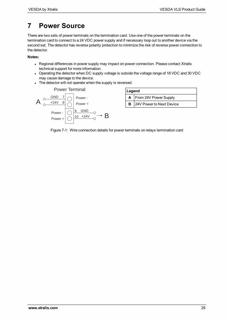
7 Power SourceThere are two sets of power terminals on the termination card. Use one of the power terminals on thetermination card to connect to a 24 VDC power supply and if necessary loop out to another device via thesecond set. The detector has reverse polarity protection tominimize the risk of reverse power connection tothe detector.
Notes:
l Regional differences in power supply may impact on power connection. Please contact Xtralistechnical support for more information.
l Operating the detector when DC supply voltage is outside the voltage range of 18 VDC and 30 VDCmay cause damage to the device.
l The detector will not operate when the supply is reversed.
Power Terminal
7
8
GND
+24VA
Power -
Power +
Power -
Power +
GND
+24V
9
10 B
LegendA From 24V Power Supply
B 24V Power to Next Device
Figure 7-1: Wire connection details for power terminals on relays termination card

VESDA VLS Product Guide VESDA by Xtralis
30 www.xtralis.com
This page is intentionally left blank.
VESDA by Xtralis VESDA VLS Product Guide
www.xtralis.com 31
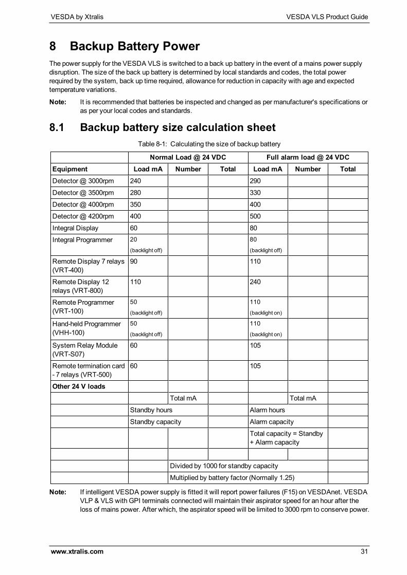
8 Backup Battery PowerThe power supply for the VESDA VLS is switched to a back up battery in the event of amains power supplydisruption. The size of the back up battery is determined by local standards and codes, the total powerrequired by the system, back up time required, allowance for reduction in capacity with age and expectedtemperature variations.
Note: It is recommended that batteries be inspected and changed as per manufacturer's specifications oras per your local codes and standards.
8.1 Backup battery size calculation sheet
Normal Load @ 24 VDC Full alarm load @ 24 VDCEquipment Load mA Number Total Load mA Number TotalDetector@ 3000rpm 240 290
Detector@ 3500rpm 280 330
Detector@ 4000rpm 350 400
Detector@ 4200rpm 400 500
Integral Display 60 80
Integral Programmer 20
(backlight off)
80
(backlight off)
Remote Display 7 relays(VRT-400)
90 110
Remote Display 12relays (VRT-800)
110 240
Remote Programmer(VRT-100)
50
(backlight off)
110
(backlight on)
Hand-held Programmer(VHH-100)
50
(backlight off)
110
(backlight on)
System Relay Module(VRT-S07)
60 105
Remote termination card- 7 relays (VRT-500)
60 105
Other 24 V loadsTotal mA Total mA
Standby hours Alarm hours
Standby capacity Alarm capacity
Total capacity = Standby+ Alarm capacity
Divided by 1000 for standby capacity
Multiplied by battery factor (Normally 1.25)
Table 8-1: Calculating the size of backup battery
Note: If intelligent VESDA power supply is fitted it will report power failures (F15) on VESDAnet. VESDAVLP & VLS with GPI terminals connected will maintain their aspirator speed for an hour after theloss of mains power. After which, the aspirator speed will be limited to 3000 rpm to conserve power.

VESDA VLS Product Guide VESDA by Xtralis
32 www.xtralis.com
This page is intentionally left blank.
VESDA by Xtralis VESDA VLS Product Guide
www.xtralis.com 33
9 Starting UpAfter installing the VESDA VLS detector it is necessary to power up the system:
The system takes approximately 15 seconds to power up
If the system fails to power up, check all power wires are secured to its terminals and the polarities of thepower wires are correctly terminated
On power up:
l The aspirator starts up and air is felt flowing out of the exhaust portl If a programmermodule is fitted, the word “VESDA” will be displayedl If a Display Module is fitted, the following indicators are lit:
l Fire Alarm Threshold indicatorsl Smoke Threshold indicators on bar graphl Two digit numerical displayl Various fault indicators if there are any faultsl System OK indicator if there are no faults
If any of the above does not happen, contact your commissioning engineer or distributor to troubleshoot.
Note: It is normal for the detector to display troubles immediately after power up. Reset the detector bypressing the reset button on the front cover of the detector to unlatch the relays and fault LEDs. Thefault LEDs on the front cover will illuminate. Proceed with the preliminary systems check.
VESDA VLS Product Guide VESDA by Xtralis
34 www.xtralis.com
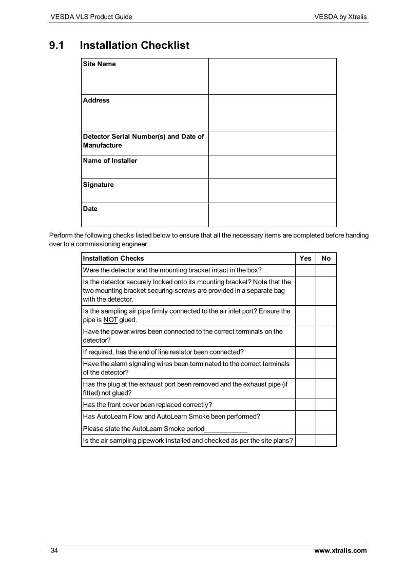
9.1 Installation ChecklistSite Name
Address
Detector Serial Number(s) and Date ofManufacture
Name of Installer
Signature
Date
Perform the following checks listed below to ensure that all the necessary items are completed before handingover to a commissioning engineer.
Installation Checks Yes NoWere the detector and themounting bracket intact in the box?
Is the detector securely locked onto its mounting bracket? Note that thetwomounting bracket securing-screws are provided in a separate bagwith the detector.
Is the sampling air pipe firmly connected to the air inlet port? Ensure thepipe is NOT glued.
Have the power wires been connected to the correct terminals on thedetector?
If required, has the end of line resistor been connected?
Have the alarm signaling wires been terminated to the correct terminalsof the detector?
Has the plug at the exhaust port been removed and the exhaust pipe (iffitted) not glued?
Has the front cover been replaced correctly?
Has AutoLearn Flow and AutoLearn Smoke been performed?
Please state the AutoLearn Smoke period____________
Is the air sampling pipework installed and checked as per the site plans?

VESDA by Xtralis VESDA VLS Product Guide
www.xtralis.com 35
10 Preliminary Systems CheckA preliminary systems check is required after installing the VESDA VLS detector, before it is commissionedfor use. The check can be conducted by connecting the detector to a LCD Programmer or using Xtralis VSCPC based software. The preliminary systems check includes:
l Conducting a VESDAnet communications checkl Selecting pipes in usel Accepting factory default configurations, or changing to site requirementsl Normalizing the air flowl Conducting a basic pass/fail smoke testl For details on preliminary systems check refer to the LCD Programmer or the relevant softwaremanuals
Refer to the VESDA LCD Programmer and Commissioning Guides for further details.

VESDA VLS Product Guide VESDA by Xtralis
36 www.xtralis.com
This page is intentionally left blank.
VESDA by Xtralis VESDA VLS Product Guide
www.xtralis.com 37
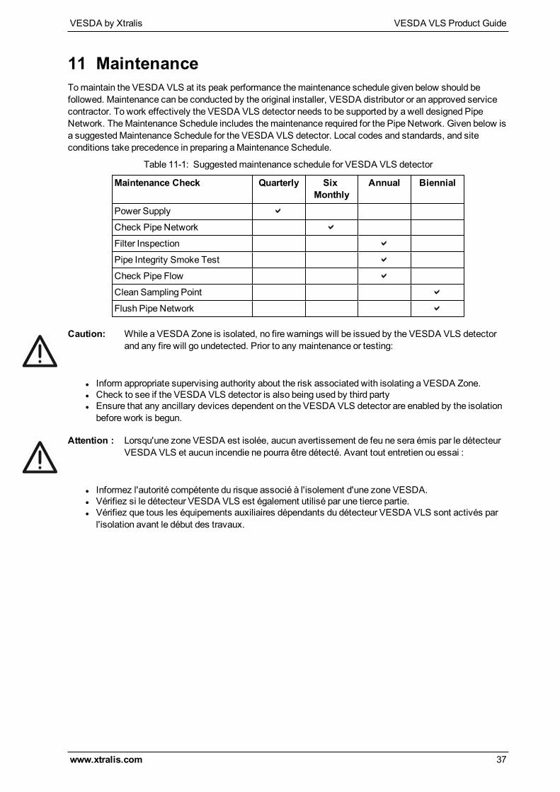
11 MaintenanceTomaintain the VESDA VLS at its peak performance themaintenance schedule given below should befollowed. Maintenance can be conducted by the original installer, VESDA distributor or an approved servicecontractor. To work effectively the VESDA VLS detector needs to be supported by a well designed PipeNetwork. TheMaintenance Schedule includes themaintenance required for the Pipe Network. Given below isa suggestedMaintenance Schedule for the VESDA VLS detector. Local codes and standards, and siteconditions take precedence in preparing aMaintenance Schedule.
Maintenance Check Quarterly SixMonthly
Annual Biennial
Power Supply
Check Pipe Network
Filter Inspection
Pipe Integrity Smoke Test
Check Pipe Flow
Clean Sampling Point
Flush Pipe Network
Table 11-1: Suggestedmaintenance schedule for VESDA VLS detector
Caution: While a VESDA Zone is isolated, no fire warnings will be issued by the VESDA VLS detectorand any fire will go undetected. Prior to any maintenance or testing:
l Inform appropriate supervising authority about the risk associated with isolating a VESDA Zone.l Check to see if the VESDA VLS detector is also being used by third partyl Ensure that any ancillary devices dependent on the VESDA VLS detector are enabled by the isolationbefore work is begun.
Attention : Lorsqu'une zone VESDA est isolée, aucun avertissement de feu ne sera émis par le détecteurVESDA VLS et aucun incendie ne pourra être détecté. Avant tout entretien ou essai :
l Informez l'autorité compétente du risque associé à l'isolement d'une zone VESDA.l Vérifiez si le détecteur VESDA VLS est également utilisé par une tierce partie.l Vérifiez que tous les équipements auxiliaires dépendants du détecteur VESDA VLS sont activés parl'isolation avant le début des travaux.
VESDA VLS Product Guide VESDA by Xtralis
38 www.xtralis.com
11.1 Replacing the chassis/Air Inlet Pipe Manifold1. Isolate the VESDA VLS by pressing the Isolate button or by selecting Isolate Zone from the Zone
menu in Xtralis VSC. This isolates the outputs from the unit to a fire alarm panel and other third partydevices such as buildingmanagement systems.
2. If you are using Xtralis VSC, highlight the detector in the Device TreeWindow and select theDevicemenu, thenSave Node Configuration. This will save the configuration details of the VESDA VLS.
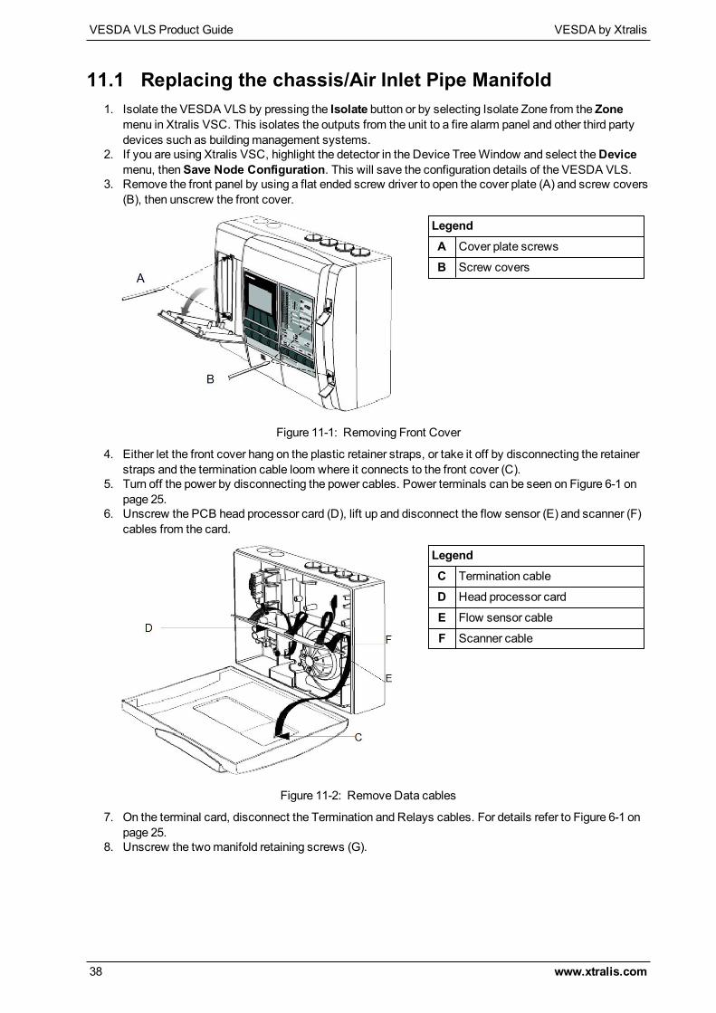
3. Remove the front panel by using a flat ended screw driver to open the cover plate (A) and screw covers(B), then unscrew the front cover.
LegendA Cover plate screws
B Screw covers
Figure 11-1: Removing Front Cover
4. Either let the front cover hang on the plastic retainer straps, or take it off by disconnecting the retainerstraps and the termination cable loom where it connects to the front cover (C).
5. Turn off the power by disconnecting the power cables. Power terminals can be seen on Figure 6-1 onpage 25.
6. Unscrew the PCB head processor card (D), lift up and disconnect the flow sensor (E) and scanner (F)cables from the card.
LegendC Termination cable
D Head processor card
E Flow sensor cable
F Scanner cable
Figure 11-2: Remove Data cables
7. On the terminal card, disconnect the Termination and Relays cables. For details refer to Figure 6-1 onpage 25.
8. Unscrew the twomanifold retaining screws (G).
VESDA by Xtralis VESDA VLS Product Guide
www.xtralis.com 39
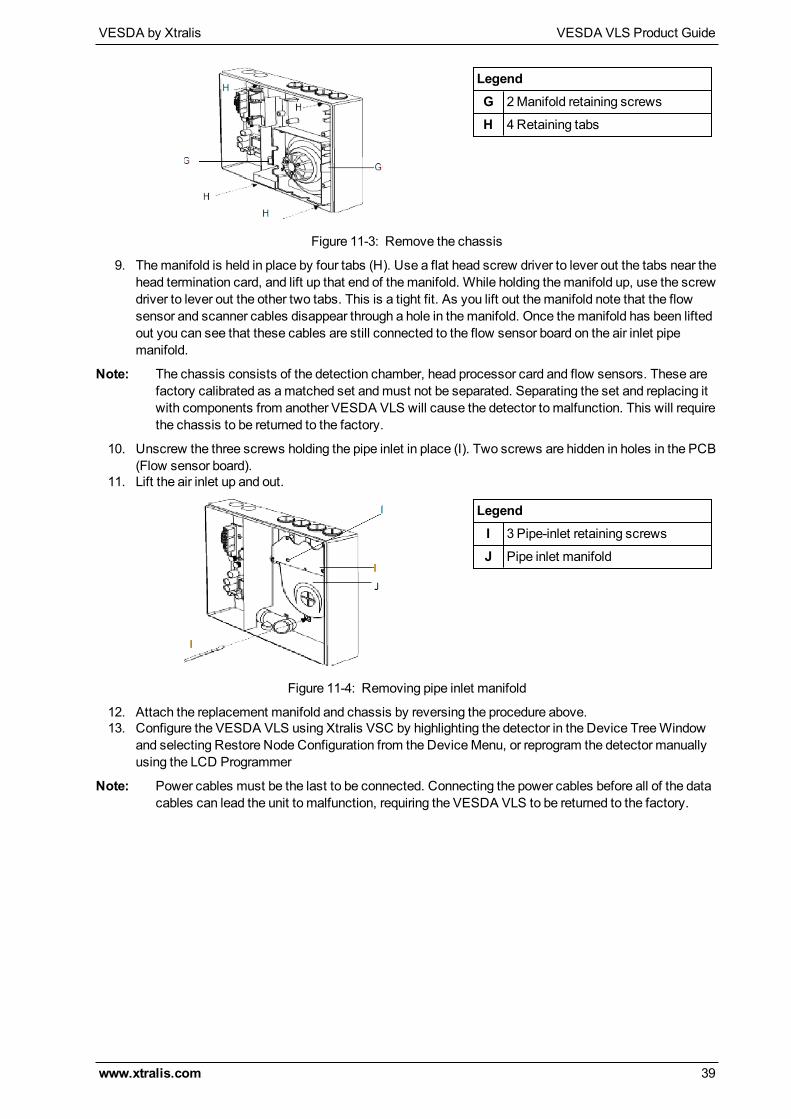
LegendG 2Manifold retaining screws
H 4 Retaining tabs
Figure 11-3: Remove the chassis
9. Themanifold is held in place by four tabs (H). Use a flat head screw driver to lever out the tabs near thehead termination card, and lift up that end of themanifold. While holding themanifold up, use the screwdriver to lever out the other two tabs. This is a tight fit. As you lift out themanifold note that the flowsensor and scanner cables disappear through a hole in themanifold. Once themanifold has been liftedout you can see that these cables are still connected to the flow sensor board on the air inlet pipemanifold.
Note: The chassis consists of the detection chamber, head processor card and flow sensors. These arefactory calibrated as amatched set andmust not be separated. Separating the set and replacing itwith components from another VESDA VLS will cause the detector to malfunction. This will requirethe chassis to be returned to the factory.
10. Unscrew the three screws holding the pipe inlet in place (I). Two screws are hidden in holes in the PCB(Flow sensor board).
11. Lift the air inlet up and out.
LegendI 3 Pipe-inlet retaining screws
J Pipe inlet manifold
Figure 11-4: Removing pipe inlet manifold
12. Attach the replacement manifold and chassis by reversing the procedure above.13. Configure the VESDA VLS using Xtralis VSC by highlighting the detector in the Device TreeWindow
and selecting Restore Node Configuration from the DeviceMenu, or reprogram the detector manuallyusing the LCD Programmer
Note: Power cables must be the last to be connected. Connecting the power cables before all of the datacables can lead the unit to malfunction, requiring the VESDA VLS to be returned to the factory.
VESDA VLS Product Guide VESDA by Xtralis
40 www.xtralis.com
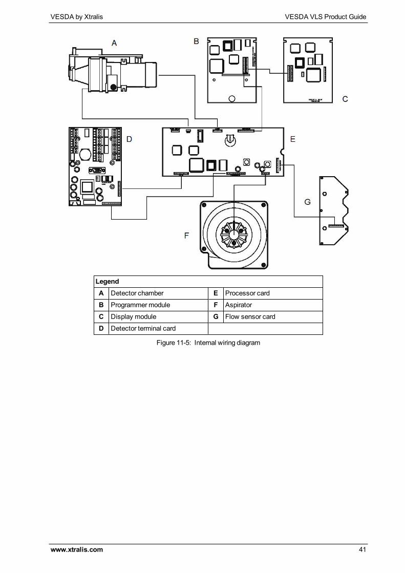
11.2 Internal Wiring for the VESDA VLSThe table below provides the cable loom interconnecting details inside the detector. Use the look up table inconjunction with the attached circuit diagram to assist with maintenance.
From To Connector card andCPU card
Cable Name # Pins
CPU card Scanner connectoron scanner valves
Scanner or X4 Scanner cable 10
CPU card Scanner connectoron sensor card
Flow sensor or X5 Flow sensorcable
10
CPU card Filter Switch Card Filter switch or X12 Fail SW 5
CPU card Termination or X1connector ontermination card
Termination or X1 Termination 13
CPU card Relays or X2connector ontermination card
Relays or X3 Relays 10
CPU card Detection chamber Pre-amp or X9 Pre Amp 6Wire ribbon
CPU card Detection chamber Laser or X10 Laser 6
CPU card Aspirator Aspirator or X11 5
CPU card Term or X1connector onprogrammer ordisplay
Expansion or X2 11
Table 11-2: VESDA VLS Internal Wiring
Notes:
l Do not disconnect the cable running between the CPU card and the detection chamber.l All connectors are polarized and can only be inserted one way into its socket.
Do not attempt to force the connector into its socket. If there is any difficulty, reverse the orientation of theconnector before inserting again.
VESDA by Xtralis VESDA VLS Product Guide
www.xtralis.com 41
LegendA Detector chamber E Processor card
B Programmermodule F Aspirator
C Display module G Flow sensor card
D Detector terminal card
Figure 11-5: Internal wiring diagram

VESDA VLS Product Guide VESDA by Xtralis
42 www.xtralis.com
This page is intentionally left blank.
VESDA by Xtralis VESDA VLS Product Guide
www.xtralis.com 43
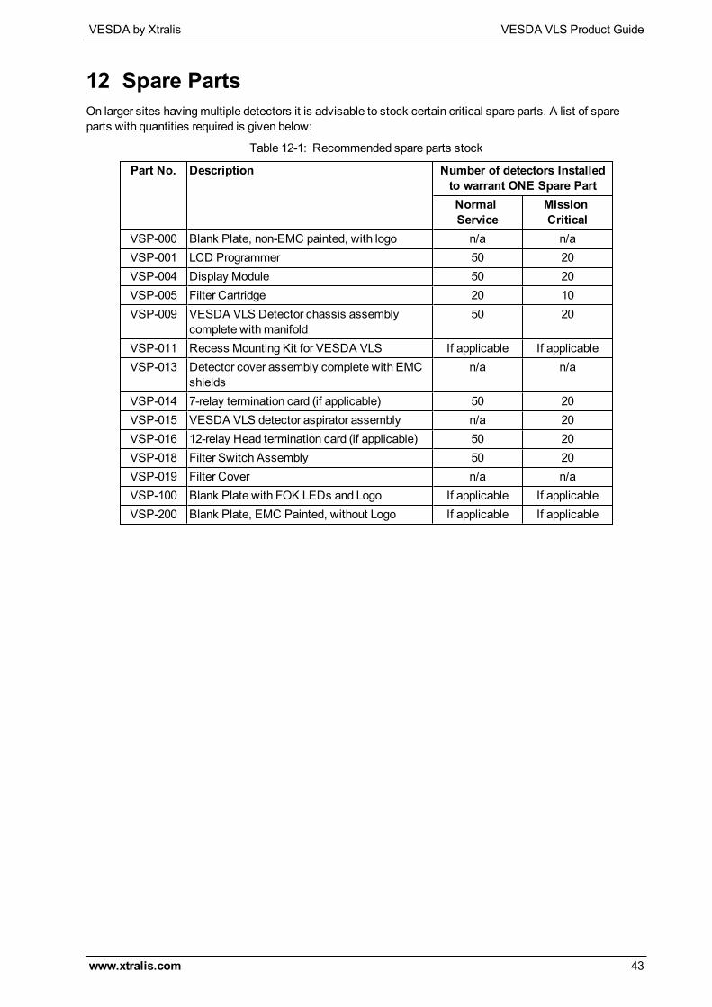
12 Spare PartsOn larger sites havingmultiple detectors it is advisable to stock certain critical spare parts. A list of spareparts with quantities required is given below:
Part No. Description Number of detectors Installedto warrant ONE Spare PartNormalService
MissionCritical
VSP-000 Blank Plate, non-EMC painted, with logo n/a n/aVSP-001 LCD Programmer 50 20VSP-004 Display Module 50 20VSP-005 Filter Cartridge 20 10VSP-009 VESDA VLS Detector chassis assembly
complete with manifold50 20
VSP-011 Recess Mounting Kit for VESDA VLS If applicable If applicableVSP-013 Detector cover assembly complete with EMC
shieldsn/a n/a
VSP-014 7-relay termination card (if applicable) 50 20VSP-015 VESDA VLS detector aspirator assembly n/a 20VSP-016 12-relay Head termination card (if applicable) 50 20VSP-018 Filter Switch Assembly 50 20VSP-019 Filter Cover n/a n/aVSP-100 Blank Plate with FOK LEDs and Logo If applicable If applicableVSP-200 Blank Plate, EMC Painted, without Logo If applicable If applicable
Table 12-1: Recommended spare parts stock

VESDA VLS Product Guide VESDA by Xtralis
44 www.xtralis.com
This page is intentionally left blank.
VESDA by Xtralis VESDA VLS Product Guide
www.xtralis.com 45
A
action 1, 3, 7, 11-12, 14, 16
adapting scan threshold 4
adaptive scan threshold 4
air filter 1, 3, 8, 10
airflow delay 14
airflow fault 8
airflow normalizing 35
alarm level
action 3, 7, 11-12, 14, 16
alert 1, 3-4, 7, 9, 11-12, 14, 16-17
fire 1 3, 5, 7, 11-12, 14, 16
fire 2 3, 7, 11-12, 14, 16
alarm levels 7, 12
alert 1, 3-4, 7, 9, 11-12, 16-17
aspirator 1, 3, 10, 14, 18, 31, 33, 40
speed 14
ASPIRE2 iv, 5
AutoLearn 1, 4, 12, 14, 34
B
backup battery
calculation sheet 31
bar graph 7
battery backup 31
C
configuration 6, 38
D
default 14
default values 14
detector chamber 1, 3, 10
detector front cover 7
device ID 14
dimensions 11, 13
display mode 14
display module 1, 4, 7, 9, 11, 20, 33, 43
E
EOL 27
event log 1, 5, 14
excessive scan cycles 4
exhaust air 24
exploded view 10
external reset 18
F
fault 7, 12, 16, 33
airflow 8
filter 8
minor 12, 16
network 8
power 8
system 8
urgent 8, 12, 14, 16
zone 8
fault LEDs 8, 33
filter 43
filter fault 8
filter service interval 14
fire 1 1, 3, 5, 7, 11-12, 14, 16
fire 2 1, 3, 7, 11-12, 14, 16
first alarm sector 4, 8, 16-17
G
GPI connections 26
GPI functions 18
I
inlet pipes 23
installation 34
intelligent sequencing 4
internal wiring 20, 40
inverted reset 18
isolate 8, 16, 18
isolate button 8, 18
Isolate LED 7
Index
VESDA VLS Product Guide VESDA by Xtralis
46 www.xtralis.com
isolate unit 38
L
loop 27
M
mains OK 18
maintenance 9, 12, 37, 40
pipe network 37
power supply 37
mode button 8
mode/test button 8
mounting 1, 19-20
N
network fault 8
normalizing airflow 35
numerical display 8
O
OK LED 7
operation 3
optical surfaces 3
P
pipe inlet manifold 3, 10, 23
pipe network 1, 3, 11, 19, 23
power 11, 29, 38
consumption 11
power fault 8, 18
power source 29
push button keys 8-9
R
referencing 12
relay settings 16-17
relays 11-12, 16, 19, 29, 33, 38, 43
remote location 7, 9
remove power 38
reset button 8, 33
reset+isolate 18
S
save node configuration 38
scan threshold 4, 12, 14
scanning 4, 9, 16
sector factor 5
sector time 4
sensitivity 1, 5, 8
slow scan 4
smoke change 14
smoke level 4, 8, 14
socket
VESDAnet 9
spare parts 43
specifications 11, 31
standby mode 18
starting up
VLS 33
system fault 8
T
termination card 9-10, 16, 19, 24-26, 29, 31,39-40, 43
threshold indicators 7, 33
threshold settings 12
U
ultra clean air 3
unlatch relays 33
urgent fault 8, 16
use night-time threshold 18
V
valve test 4
VESDAnet 9, 18
VESDAnet closed loop 26
VESDAnet terminals 26
W
weight 11
wiring 11, 20, 27, 40
address loopmodule 27
wiring connections 25
VESDA by Xtralis VESDA VLS Product Guide
www.xtralis.com 47
Z
zone fault 8
zone number 8

VESDA VLS Product Guide VESDA by Xtralis
48 www.xtralis.com
This page is intentionally left blank.