
Capability maturity model for arcon implementation for e government services

.'VDLLUME 41PROGRAM IMPLEMENTATIONAND MATURITY
REPORTTOTHE ADMINISTRATORBY
THENASAAEROSPACESAFETYADVISORY/PANEL j
ON THESKYLAB PROGRAM
JANUARY 1973
(NASA-TM-X-66815) REPORT TO THE N75-23645ADMINISTRATOR BY THE NASA AEROSPACE SAFETYADVISORY PANEL ON THE SKYLAB PROGRAM.VOLUME 2: PROGRAM IMPLEMENTATION AND UnclasMATURITY (NASA)_ 180 p HC $7.00 CSCL 22B G3/15 17572

ERRATA SHEET
for
Volume II Panel Report on Skylab Program
Page No. Location and Correction
60 1st line, top of page. Change "rodent" to "rod end".2nd line from bottom. Change "pure" to "purge".
71 3rd paragraph, 2nd line. 0hange"there" to "these"
90 1st line, top of page. Change "stickly" to "Sticky".4th line from top. Eliminate the word "Minor". Shouldread "Items open at....."
103 Item 2. Environmental and Thermal Control. Item (b) (1),remove "ECD". Item (b) (4) change "head" to "heat".
118 2nd paragraph, 4th line. Change "CSC" to "KSC"
127 Item 4 above "Multiple Docking Adapter". Remove "life test"at the end of the line.
129 3rd paragraph, 2nd line. Change "utilization" to "Integration".145 2nd paragraph, 2nd line. Change "influence" to "Influenced"
146 Ist line under "Crew Operations". Change "experimental"to "experiment".
151 2nd paragraph, 6th line. Change "assured" to "assessed".

SKYLAB PROGRAM
A REPORT TO THE ADMINISTRATOR
by
THE NASA AEROSPACE SAFETY ADVISORY PANEL
Volume II - Program Implementation and Maturity
January 1973

PREFACE
This volume discusses the maturity of the modules as evidenced
during the design and manufacturing reviews, and reviews the scope of
the cluster risk assessment efforts and their results. Inherent in this
discussion is an assessment of the technical management system and
its capability for assessment and resolution of problems.
The detail in volume II supports the conclusions and recommenda-
tions in volume I.
In addition, a number of specific "open items" are identified
during the course of the discussion. While it is anticipated that they
will be closed as the program progresses, the Panel is asking for a
formal disposition to assure themselves closure was in fact achieved.
PRECDING PAGE BLANK NOT FILMED
iii

CONTENTS
Page
SUMMARY .............. ..... .... ................ vii
ABBREVIATIONS, ACRONYMS, AND DEFINITIONS ................ xi
PANEL ACTIVITIES SCHEDULE ........................... xiii
RISK ASSESSMENT .................................. 1
RELIABILITY, QUALITY, AND SAFETY ..................... 1
SKYLAB MEDICAL EXPERIMENTS ALTITUDE TEST (SMEAT) ......... 9
CLUSTER FAULT CURRENT PROTECTION .................... 13
SNEAK CIRCUIT ANALYSIS ............................ 15
MICROBIAL CONTROL ............................... 17
CLUSTER CONTAMINATION CONTROL ...................... 20
CLUSTER MATERIALS ............................... 23
FIRE DETECTION, CONTROL, AND EXTINGUISHMENT .............. 25
HARDWARE/SOFTWARE ASSESSMENT ....................... 31
MISSION OPERATIONS ............................... 31
ASSESSMENT OF MISSION OPERATIONS ..................... 45
COMMAND AND SERVICE MODULE ........................ 46
ORBITAL WORKSHOP................................ 51
AIRLOCK MODULE ............................................ 110
MULTIPLE DOCKING ADAPTER ......................... 127
PAYLOAD SHROUD ................................. 137
APOLLO TELESCOPE MOUNT ........................... 138
EXPERIMENTS ............ ..... ................... 144
BIBLIOGRAPHY .................................... 158
PREC: DING PAGE BLANK NOT FILMED

SUMMARY
Volume II provides the detailed material on which the Panel's conclusions and
recommendations are based. In addition, the material presented in the SUMMARY rep-
resents significant areas taken from the details of this volume. To assure that the
Administrator is provided adequate background on the Skylab mission items such as
those noted here should be covered in Skylab presentations to him.
1. Reliability, quality, and safety: Open items at the time of the Panel reviews in-
clude the following:
(a) Completion of the sneak circuit analysis for the total space vehicle
(b) Completion of the testing associated with corona assessments
(c) Problems associated with the suit drying station and the availability of the
suits in case of emergencies
(d) Crew procedures for reaction to the loss of cluster pressure
(e) Further studies on the susceptibility of crew to dangers due to the inhalation
of particulate matter during earth orbit conditions
2. Manufacturing, workmanship, and vendor control: At each contractor visited by
by the Panel a self-assessment was provided by the contractor in terms of the recom-
mendations made by the Centaur and Thor/Delta Review Boards (reports issued in
1971). Obviously, no self-assessment can give the full assurance that would result from
a detailed onsite audit. However, the Panel found that, in fact, these self-assessments
when backed by NASA audit teams and astronaut comments did provide confidence in
workmanship and vendor control aspects of contractor's activities.
3. Fire prevention, control, and extinguishment: The reviews of individual mod-
ules, mission operations, and associated areas indicate that these most important safety
areas have been, and continue to be, a mainstream effort throughout the program. The
philosophy of fire prevention appears to have been adhered to strictly. Thus, while
there are significant quantities of flammables on board the cluster (for example, OWS
wall insulation, Coolanol-15 as a refrigerant, various materials contained in experi-
ments), there has been a careful and thorough effort to minimize the quantities of such
materials. Where they do exist the effort has been toward their isolation from each
other and from both ignition sources and flame propagation paths. However, since this
is not completely possible, fire escape plans and fire extinguishment techniques take on
added significance. There is every indication that this area is receiving the necessary
vii
pRECEDING PAGE BLANK NOT FILM D

emphasis. Nonetheless, continued attention is required to maintain awareness andthose necessary communications between personnel and organizations which will pre-clude anything entering the system that would adversely affect the fire situation. House-keeping involving thousands of items is of course critical to control of the hazards lead-ing to fires.
4. Results of Skylab medical experiments altitude test (SMEAT): This test sub-jected three crewmen to the rigors of a 56-day simulated Skylab mission. Data reduc-tion and handling proved adequate. Experiment operating procedures, medical teamtraining, and pre- and postmedical flight data and procedures were evaluated. A medi-cal baseline was established and principal investigator participation was explored. Thetest, based on available data, was most successful. It did, however, surface numerousoperational procedures which were cumbersome as well as a large number of hardwareproblems. This of course is the reason for running the test in the first place. At thetime of the Panel's review of the SMEAT data five items were still in work, not countingthe documentation requirements being factored into the operational data. These fiveitems were
(a) Ergometer anomalies
(b) Urine collection insufficiencies
(c) Metabolic analyzer anomalies
(d) Food system problems (minor nature)
(e) Erratic operation of the blood pressure measuring system (minor nature)Those manned altitude tests conducted after SMEAT will no doubt be used to verify theresolution of most of the SMEAT aired problems.
5. Microbial control: Apparently an exact definition of system requirements formicrobial thresholds under Skylab environmental conditions, zero-G and low pressure,cannot be provided. Therefore, the objective of the microbial control program is tominimize the implantation of microorganisms and their growth rate. The establishmentof the Skylab intercenter microbial control working group in 1970 has gone a long waytoward meeting these objectives. Methodology has centered on pinpointing those areaswhere relatively large numbers of organisms could accumulate and receive nutrients.This area of endeavor will require operational surveillance during the mission itself aswell as strict premission controls.
6. Contamination control: The Skylab organization, with the continuing support ofthe contamination control working group, has directed a steady effort to identifying con-
tamination sources, assuring adequate material controls, and maintaining hardwarecleanliness. To further assure clean conditions the premission and mission operational
documentation and mission training efforts are directed toward the same goals. Test
programs over the last year have provided valuable data on sources of contamination and
possible solutions for the protection of susceptible hardware.
viii

7. Experiments: The number, type, and sophistication of the experiments carried
in the Skylab cluster present a very complex technological and administrative task.
Problems encountered during the development and testing of the experiments have been
as diverse and difficult as any found on the basic Skylab modules themselves. The
management systems operating at each Center now appear to be doing the necessary job
of providing proper experiment hardware and operating procedures. Those experiments
involving two sponsoring Centers, of course, require more detailed coordination and
specific documentation. With the experiments being delivered to the KSC it is also
necessary that the principal investigators are appropriately involved during the test and
checkout periods at KSC. This is a must to ensure that their experiment hardware is
properly exercised and that any problems are resolved quickly and with the least per-
turbation on the overall KSC schedule. The system for defining priorities for the ex-
periments and the assessment of payoff during the mission warrants particularly greater
attention. This area has not been defined as far as the Panel reviews are concerned.
8. Command and service modules: Since the Skylab CSM's constitute a modification
to the very successful Apollo CSM's and the contractor appears to be maintaining ade-
quate skills and engineering capability, there is a high degree of confidence in the CSM's
ability to do its assigned job. Apollo 17 problems will of course need to be evaluated
for their impact on Skylab. The following items were noted by the Panel during its re-
views:
(a) Adequacy of the tension-tie cutter and explosive charge system
(b) Qualification of the descent battery
(c) The discharge and/or safing of the RCS propellant system during reentry
9. Qualification tests: Those qualification tests still incomplete at the time of the
Panel's review (November 1972) included the following number of tests against each of
the modules:
Module Number
of
tests
Orbital workshop 28
Airlock module 10
Apollo telescope mount 4
Payload shroud 1
Multiple docking adapter 0
ix

ABBREVIATIONS, ACRONYMS, AND DEFINITIONS
The following are abbreviations, acronyms, and definitions used in this volume:
Skylab orbital assembly (OA):
AM Airlock module
MDA Multiple docking adapter
OWS Orbital workshop
CSM Command and service module
ATM Apollo telescope mount
IU Instrument unit
Major module systems:
ECS Environmental control system
TCS Thermal control system
EPS Electrical power system
HSS Habitability support system
CAS Crew accommodation system
SAS Solar array system
Other major hardware:
PS Payload shroud
L/V Launch vehicle
SAT-V Saturn V launch vehicle
SAT-IB Saturn IB launch vehicle
GSE Ground support equipment
CFE Contractor furnished equipment
GFE Government furnished equipment
MCC-H Mission Control Center - Houston
LCC Launch Control Center
EREP Earth resources experiment package
C&D Control and display
Skylab reviews, mission terms:
SOCAR Systems/operations compatibility assessment review
DCR Design certification review
PDTR Predelivery and turnover review
COFW Certificate of flight worthiness
FRR Flight readiness review
FMEA Failure mode and effects analysis
SFP Single failure point
SMEAT Skylab medical experiments altitude test
xi
PRECEDING PAGE BLANK NOT FILMED

EVA Extravehicular activitySL-1 First Skylab launch: Saturn V and orbital assembly less CSMSL-2 Second Skylab launch: Saturn IB with CSM 116SL-3 Third Skylab launch: Saturn IB with CSM 117SL-4 Fourth Skylab launch: Saturn IB with CSM 118
NASA and industry organizations:
OMSF Office of Manned Space Flight, Washington, D. C.MSFC Marshall Space Flight Center, Huntsville, AlabamaMSC Manned Spacecraft Center, Houston, TexasKSC Kennedy Space Center, Florida
MDAC-W McDonnell Douglas Astronautics Company, Huntington Beach, CaliforniaMDAC-E McDonnell Douglas Astronautics Company, St. Louis, MissouriMMC Martin Marietta Corporation, Denver Division, Denver, ColoradoNR North American Rockwell Corporation, Downey, California
Definitions:
Saturn workshop Inorbit space assembly which includes the orbital workshop(OWS), airlock module (AM), multiple docking adapter(MDA), and the Apollo telescope mount (ATM).
Orbital assembly or Saturn workshop plus the docked CSM.cluster
Group- related ex- Experiments that are closely related to each other eitherperiments through common focus of study or by integration into a singlc
subsystem. These are the medical experiments, solarastronomy (ATM), and Earth resource experiments.
Corollary experi- Experiments other than group related or passive type that re-ments quire significant in-flight crew support and are not closely
related to each other.Passive experi- Experiments whose associated in-flight crew support require-
ments ments are almost nonexistent.Constraint Restriction that influences the mission profile, or timeline,
and for mission planning purposes cannot be violated.Single failure point Single item of hardware which, if it failed, would lead directly
(SFP) to loss of a part, system, mission, or crew member.Principal investigator Individual NASA has contracted with for the development and
(PI) delivery of experiment hardware, analyses of returned data,or both.
xii

PANEL ACTIVITIES SCHEDULE
Phase I
September 14-15, 1971 Washington, D.C. (OMSF and Skylab Program)
October 18-19, 1971 McDonnell Douglas, Huntington Beach, California
November 8-9, 1971 McDonnell Douglas, St. Louis, Missouri
December 13-14, 19I1 Washington, D.C. (Life Sciences Division)
January 10-11, 1972 Martin-Marietta Corporation, Denver, Colorado
February 14-15, 1972 North American Rockwell Corp., Downey, California
March 13-14, 1972 Chrysler/Boeing/MSFC Launch Vehicle, Michoud,
Louisiana
Phase II
April 10-11, 1972 MSFC, Skylab Program Office, Huntsville, Alabama
May 8-9, 1972 MSFC, Skylab Program Office, Houston, Texas
June 12-13, 1972 KSC, Skylab Program Office, Cape Kennedy, Florida
June 19-23, 1972 OWS Pre-DCR, MDAC-West, Huntington Beach,
California
July 13, 1972 MSFC Skylab Experiments Pre-DCR, Huntsville,
Alabama
July 27, 1972 Saturn I-B Turnover Meeting, Michoud, Louisiana
August 10-11, 1972 Formal DCR for CSM and Selected MSC Experiments,
MSC, Houston, Texas
August 31 - Sept. 1, 1972 Pre-DCR Mission Operations, MSC, Houston, Texas
September 5-6, 1972 OWS PDTR at MDAC-West, Huntington Beach,
California
September 12-14, 1972 ATM Product Turnover Review, MSC, Houston, Texas
September 15, 1972 DCR for Mission Operations, MSC, Houston, Texas
September 28, 1972 SMEAT Review, MSC, Houston, Texas
September 27-29, 1972 AM/MDA Acceptance Review, MDAC-East, St. Louis,
Missouri
October 2-3, 1972 DCR-Module and Experiment Hardware, MSFC,Huntsville, Alabama
November 9-10, 1972 Washington, D.C. (Skylab program update)
xlll
RISK ASSESSMENT
RELIABILITY, QUALITY, AND SAFETY
The reliability and safety program defines and integrates the activities of Headquar-
ters, the operating Centers (MSFC, MSC, KSC), and the contractors. It provides guid-
ance, disciplines, and assessment during all phases of design, manufacturing, test,
preparation, and mission operations. The experience of NASA and its contractors in
both manned and unmanned space missions has been applied at each level of the program.
Experience as documented in the MSC 00134 Report "Space Flight Hazards Catalog" and
the MSC "Manned Spacecraft Criteria and Standards" along with similar launch vehicle
material was used extensively. The results of the Centaur and Thor/Delta Review
Boards were factored into the program in late 1971 to assure appropriate workmanship.
Contractors developed system safety program plans and instructions on their implemen-
tation. Each affected organization throughout the program had dedicated personnel in
these areas. Motivational programs have been continued and strengthened during the
lifetime of the Skylab program.
The purpose herein is to discuss the procedures and their implementation. In so
doing the report assesses the extent that this provides confidence in the hardware and
documentation. Related efforts, discussed elsewhere in this report, include sneak cir-
cuit analysis; falut current protection; habitation area pressure integrity review
(covered in each module); cluster materials; fire detection, control, and extinguish-
ment; and contamination control.
For each design review and "turnover" acceptance meeting, a reliability and safety
analysis has been provided by both the contractors and NASA. These appear to be thor-
ough. They follow the basic system originally used during the Apollo program with ex-
cellent results. MSC and the crews have instituted very thorough safety efforts on any-
thing relating to "man. " Some of these efforts are borne out in MSC's "Manned Safety
Assessment for Skylab" reports concerning each item of MSC responsibility as well as
the operational aspects of the mission. MSC has produced an "Index of MSC System
Safety Studies" (Report No. SN-5-71-43 Rev. B, May 1, 1972) which serves as a base-
line for such work. MSFC through its resident offices has exerted continuing pressure
to assure that reliability and safety goals were practical and were met to the maximum
degree. A part of any reliability and safety program is the support obtained from the
configuration management (CM) systems. This assures that reliability and safety groups
1

have the opportunity to assess all changes, know the "as-designed" versus "as-built"hardware, and assure the traceability of hardware and component materials. Thus, CMplays a role in any discussion of reliability, quality, and safety.
Management policies have been initiated at the Headquarters level. Implementingpolicies and procedures have been developed by NASA centers and contractors. As anexample, the following directives are issued and interpreted by the Program Office inWashington:
P.D. #9 Reliability, Quality, and Safety AuditingP.D. #10A Nonconformance Reporting and Corrective ActionP. D. #11A Sequence and Flow of Hardware Development and Key Inspection, Review
and Certification CheckpointsP. D. #13 Failure Mode and Effect Analysis - Single Failure Point Identification
and ControlP.D. #16A Skylab Materials PolicyP. D. #31 Implementation of System Safety Requirements
The Program Office maintains visibility and control by participation in reviews and con-duct of audits:
Intercenter panels, CCB participationFormal reviews, DCR's, etc.Safety technical interchange meetingsRQ&S quarterly meetings of Centers and HeadquartersAudits of center safety related activitiesParticipation in NASA-wide panels and advisory groups such as the Spacecraft Fire
Hazard Steering Committee, NASA Hazards Identification Committee, NASAParts Steering Committee, Contamination Working Group
Reliability
The basic approach is to concentrate attention on hardware and operational itemscritical to crew safety, mission success, and launch operations. These efforts could beclassed under the following subheadings: system reliability analysis, design support,and production and test support.
The basic analytical efforts are the failure mode and effect analyses (FMEA).Based on the FMEA, the following work is carried out:
Identification of single failure pointsIdentification of launch critical componentsCaution and warning system analysis
2

Critical redundant/backup components
In-flight maintenance
Single failure point retention rationale
Criticality analysis
Criticality ranking
Identification of mission/safety critical items
Design support includes those activities associated with in-flight maintenance evalua-
tions, parts and material programs, design review programs, configuration control, and
supplier reliability requirements and implementation. The results of systems reliability
analyses are used as the basis for determining what hardware items should have in-flight
maintenance. This is the foundation on which in-flight spares, tool requirements, and
crew contingency procedures are established. The parts and material programs provide
for the selection and control of parts and materials used in each module: These include
selection and standardization, specifications, qualification tests, parts usage control,
and derating requirements. The design review program includes informal reviews
within the design technologis, formal design reviews by a single review board, and the
basic drawing release system which ensures review and approval by appropriate tech-
nologies and agencies during the drawing release. Also included is the review and ap-
proval of design specifications. The reliability effort includes the review of all engineer-
ing change proposals and attendance at Configuration Control Boards to assure proper
attention to the RQ&S areas. Supplier reliability requirements and their implementation
are imposed and audited to meet program specifications.
Production and test support provided in the reliability area includes those activities
tied to the test documentation, failure reporting system, failure analyses, problem con-
trol centers, monitoring of all testing, and the necessary followup to assure resolution
of hardware test anomalies.
Based on the material presented to the Panel during its reviews at the contractor
plants and at NASA centers, the efforts noted previously appear to be well founded on
the experience of prior programs and implemented by experienced and competent per-
sonnel. For example, when checked against the findings and recommendations of the
Centaur and Thor/Delta Review Boards, the reliability efforts on the Skylab are adequate.
Because of the importance of the FMEA work it is well to further discuss and under-
stand it. The mission level FMEA has several important functions. It doublechecks,
evaluates, and validates lower level inputs for adequacy and accuracy (modules, subsys-
tems, components). It examines failure modes across interfaces to discern critical ef-
fects. The mission level FMEA, as distinct from the lower level FMEA, is based on
composite schematics across the module interfaces. This enables an analysis of the
functions required to cause all mission events to occur. These data are then analyzed for
the failure modes that can cause loss of those functions. This type of knowledge is con-
sidered of prime importance to mission planning and operations. The dispositioning of
3

single failure points is delineated by means of a Pert-type system which typifies the
relationship of the module and mission level FMEA events and activities. MSFC Direc-
tive MPD 8020.4 shows the necessary activities that take place as a result of contractor,intra-, and intercenter interfaces to dispose not only of single failure points identified
but all other action items resulting from these analyses. This then indicates that a
closed-loop system does indeed exist. It is an iterative management control process
embracing survey, audit, and monitoring activities. These data are then used by thedesign, quality assurance, test, operations, and safety discipline areas.
Quality Assurance
The prime objective of the quality programs is to provide those functions necessary
at the NASA/contractor sites to produce Skylab hardware that meets the requirements of
the specifications and is defect-free. The basic NASA documents used in this are NPC
200-2, NHB 5300.5, and NHB 5300.4. Here again the activities and methods used indi-
cate that the Centaur and Thor/Delta problems do not significantly exist on Skylab. The
audits conducted by the NASA quality groups and the contractors of their suppliers sup-
port this conclusion. The results of tests and the failures noted by the Panel at its re-views are also indicative of quality workmanship equal to that found on the later Apollo
hardware. The fact that one can point to many problems with the manufacture of inte-
grated circuits (cracked solder) and other similar types of workmanship problems is
more indicative that the system is good enough to catch these problems before they reach
the final "ready-to-launch" hardware. The screening of hardware from the initiation of
manufacture through the prelaunch checks should provide confidence that only good qual-
ity items will appear on the vehicles.
Safety
Safety tasks were evident in the design, development, manufacturing, assembly,
checkout and acceptance, and operational mission planning. Tasks associated with the
system safety effort include safety analyses and postanalyses actions, safety reports,
safety review functions, explosive and ordnance safety, ground handling and transporta-
tion, tests, training and certification, and systems installation.
System safety analyses of the modules and supporting GSE are performed to identify
and evaluate hazardous conditions that may exist during all mission phases. The hazard
criticality of module components, critical functions, and critical operations have been
determined and evaluated. Appropriate corrective measures to eliminate or alleviate
the hazard to an acceptable level have been effected in most cases. The following hazard
4

identification techniques have been employed:
Review of the FMEA for safety significant items
Review of ECP's for safety impact
Review of all prior safety related history for impact
Special safety studies in support of design, test, and operations
Direct and continuing participation in test plans and operations, reviews, etc.
Safety assessment of failure reports
System safety checklist development and implementation
The results of system safety analyses and reviews noted previously are documented
safety assessments and "alert system" reports. Documentation and test plans are re-
viewed to identify safety significant operations and methods.
Ground handling and transportation, an important phase of Skylab, has encompassed
a wide variety of efforts. These include training of personnel, design of equipments for
transport of hardware, and maintenance of cleanliness standards.
An integral part of the safety program is the training of personnel at all levels to be
proficient in the performance of their jobs. This includes the motivational programs
within the factory and at KSC.
An example of the safety office role in support of the Skylab program is that of the
MSC Safety Office. Basically this office plans, directs, and coordinates the development
and implementation of the MSC Skylab safety program in line with established directives.
Of particular note is their support of milestone reviews, safety analyses, participation
in test activities, and the monitoring of mission activities.
They have etablished a flexible but comprehensive approach to hazard identification
and control. Thi; includes the following:
1. Contractor provided safety program (fig. 1). Here the contractor provides the
total safety plan and performs design hazard analysis, operational hazard analysis, and
provides a final safety assessment.
2. Contractor assisted safety program (fig. 2). Here the contractor provides a
safety representative and the hazard summary with NASA carrying the main burden.
3. MSC Safety Office provided safety program (fig. 3). Here the MSC organization
conducts the design hazard analysis, safety assessment, and crew procedure reviews.
MSC makes extensive use of independently prepared safety analyses by safety profes-
sionals.
MSFC, with the support of their integrating contractor MMC, developed a series of
Skylab system safety checklists. The objective of this program was to summarize the
actual status of the Skylab design and operational conditions which could result in sys-
tems failure, equipment damage, or personnel injury. These checklists also provide
management visibility of the effectiveness of hazard identification and control activities.
It also is an aid for effective implementation of followup actions. Typical source data
5

CONTRACTOR PROVIDED SAFETY PROGRAM
CONTRACTOR'S CDESIGN CREW
STANDARDS PROCEDURES
CONTRACTOR's PRELIMINARY PRELIMINARY FINAL FINAL REVIEW OPERATIOiALSAFETY HAZARDS SAFETY HAZARD SAFETY CHANGE HAZARDEFFORT ANALYSIS ASSESSMENT ANALYSIS ASSESSMENT SFTY. IMPACT ANALYSIS
CONTRACTOR'S PRELIMINARYRELIABILITY PRELIMINARY FINAL
EFFORT FMEA FIIEA
PRR D PDR CDR ECP CARR
SC REVIEW REVIEW ASSURE REVIEWISC SAFETY DESIGN DESIGNREVEW SAFETY SAFETYSAFETY REQUIRE- AND CHANGEOFFICE REQ E- AiD AND AFE CHANGES CHANGES TOOFFIC EIMENT SASFETFFORTS SAFETY SAFETY ICORPORA- CREW PRO-ACTIVITIES ACTIVITIES IPACT TIONL CEDURES
FIGURE 1

CONTRACTOR ASSISTED SAFETY PROGRAM
CONTRACTOR'S SAFETY SAFETYSAFETY - REPRESENTATIVE REPRESENTATIVEEFFORT I UT INPUT
CONTRACTOR PRELIMINARY FINAL HAZARDRELIABILITY FHEA FHEA SUI. ,ARY
EFFORT
PRR -PDR CDR ECP - CARR
REVIEW ASSURESC SAFETY REVIEW CHAGE SAFETY
SAFETY - REQUIRE- DESIGND ----- SAFETY CHAGESREOFFICE 1ENTS HAZARD INCORPORA-EFFORTS SUIIARY TION
FIGURE 2

SAFETY OFFICE PROVIDED SAFETY PROGRAM
RELIABILITY PRELIMINARY FINAL
EFFORT FIEA FMEA
PRR PDR CDR ECP CARR
REVIEW ASSUREKSC SAFETY PERFORM DESIGN REVIEW SAFETY REVIEW
SAFETY -- REQUIRE- REVIEW HAZARD PERFORM CHAGE CHANGES CREWOFFICE ENTS ANALYSIS SAFETY T INCORPORA- PROCEDURES
EFFORTS ASSESSMENTS TION
FIGURE 3

for the checklist development were derived from the documents shown in table I.
Safety assessments have been made for individual modules and launch vehicles as
well as the Skylab systems across the cluster (total orbiting hardware). This activity,
done in support of the design certification reviews, will continue through launch prepara-
tion and the mission as required. Manned safety assessments of the operations area are
still being conducted as the mission documentation is prepared and hardware moves
through KSC test, checkout, and launch preparation. If all available material from
hardware assessments is used, this work will identify potentially hazardous operations,
provide substantiating data that safety requirements are satisfied, and will indicate
where additional contingency procedures development may be required for crew safety.
Program management is currently emphasizing this aspect of the safety work to assure
completion on time and with adequate coverage. At the time of the review by the Panel,
88 safety tasks had been identified. These tasks covered the mission events from pre-
launch through landing, recovery, and rescue. Of these 88 safety tasks, 48 are still to
be completed. The incomplete tasks include analysis of lightning strikes, solar heating
of service module reaction control system during rendezvous and docking, and some of
the cluster on-orbit operations in the fields of activation, habitability, emergency oper-
ations, and subsystem operations.
Among the "open items" of interest are the following:
1. Sneak circuit analysis
2. Corona assessment
3. Susceptibility of crew inhalation of particulate matter within the cluster during
Earth orbit
4. Suit drying system problems and suit availability for emergencies
5. Safety analysis of partial loss of solar array power and the definition of candidate
loads for a power down
6. Detailed crew procedures for reaction to AP alerts
Skylab rescue is discussed in the MISSION OPERATIONS section of this report.
From the safety standpoint the rescue is not considered to be time critical since it is
assumed the cluster is habitable. Identified hazards in the rescue spacecraft include the
couch assemblies installed in the lower bay, center couch ballast, and the oxygen umbil-
icals and "Y" adapters. Tests and analysis indicate minimal risk.
SKYLAB MEDICAL EXPERIMENTS ALTITUDE TEST (SMEAT)
Test Description and Objectives
The Skylab medical experiments altitude test was a 56-day chamber test performed
at MSC. It used the Crew Systems Division's 20-foot-diameter altitude chamber. Skylab
9

00'
1,2, & 3 - TV Camera (overheadinstallation)
4 - M 171 Ergometer5 - Food preparation table
36,7,8,9,10, 11 - Intercoms
-29 35 12,13, & 15 - Stowage (head area)14 - Sink
28 3116,17, & 18 - Stowage (personnel40 40sleep area)
32I 13 19 - Off-duty equipment38 =20 & 21 - Stowage (lounge area)
33 12 114 22 - ESS rack
23 - M 171 MA rack
5 15 0 24 - Experimental trash stowage
37 25 - Camera and photo stowage1~ 926 - Medical stowage
42 1 27 - NASA Hdq stowage
37 28 - Fecal bag stowage
26 25 r29 - Vac bag, hygiene, andthermoglove stowage
2 30 - Refrigerator/freezer2k 131 - Tools and trash stowage
19 32 - Galley33 - Trays and food stowage
3-f 35 - Urine chiller36 & 37 - Ladder38 - Transfer lock
339 - M 133 sleep monitor
22 41 40 - Head
41 - TV display42 - CO monitor43 - Speaker entertainment
stations
FIGURE 4. CHAMBER ARRANGEMENT

environment and protocol were duplicated as closely as possible.
The test objectives were as follows:
1. The primary objective was to obtain and evaluate baseline medical data for
56 days on those medical experiments which reflect the effects of the Skylab environment.
This included microbiological data and additional biomedical data unobtainable in flight.
2. The secondary objectives were to (1) evaluate selected experiments hardware,
systems, and ancillary equipment, (2) evaluate data reduction and data handling proce-
dures in a mission duration time frame, (3) evaluate preflight and postflight medical
support operations, procedures, and equipment, (4) evaluate medical in-flight experi-
ment operating procedures, and (5) train Skylab medical operations team for participa-
tion during real orbiting flight.
The test started on July 26, 1972 and was completed on September 20, 1972. A
final report is expected in January 1973.
The layout in the MSC 20-foot chamber was similar to the lower deck of the OWS.
It included a waste management area, galley, crew sleeping quarters, and an experiment
operation area. These are shown in figure 4. An upper deck area was set up for off-
duty crew activities. Chamber modifications affecting the human medical data were
made as close to Skylab flight hardware as practical. Other chamber modifications had
Skylab hardware appearance but did not function as the flight hardware in order that costs
could be held down. Crew activities were conducted according to the mission-like flight
data file which was modified to fit the SMEAT test configuration. Communications con-
ducted during the test period followed Skylab protocol except for equipment repair and
safety activities.
The medical experiments and other Skylab equipments used and evaluated during the
test are defined in table II.
During the Panel's attendance at the various DCR, PDTR, and spacecraft acceptance
activities the impact of the SMEAT results during and after the completion of the test
were noted. Most of the problems that surfaced during the SMEAT have been, or are in
the process of being, factored into the flight hardware at this time.
Experiment Support Medical Requirements
Flight-type qualification preflight and postflight physical examinations were per-
formed prechamber and postchamber. In-chamber exams, administered by physician
crewman, were required for in-flight medical support system (IMSS). Vision and audi-
ometry testing and chest X-rays were done prechamber and postchamber.
The SMEAT surfaced both operational and hardware problems. This of course is
the reason for such development tests. A partial list of these problems is noted here.
The Panel is awaiting the release of the SMEAT report for further data.
11

M092 - Lower body negative pressure experiment:
1. Differences between BPMS reading and blood pressure obtained by clinical tech-
niques. (Problem may not be real - tests to be done to verify.)
2. BPMS occasionally reads 001 for systolic pressure.
3. Leg bands require calibration and incorporation of foam spacers.
4. Waist seal subject to leakage and damage. May need to carry in-flight spare.
5. Problem with isolation from VCG signals.
M093 - Vectorcardiogram experiments:
1. VCG cable length needs to be increased for use on ergometer.
2. Electrode sponges have caused variation in electrode impedance.
3. Heart rate readout occasionally hangs up at upper limit.
M074 - Small mass measuring device:
1. Elastomer retention sheet tore loose in use.
M133 - Sleep monitoring experiment:
1. Cap sizing critical to comfort. Must provide correct size for designated crew-
men.
2. Electrode material caused allergic reaction on some crewmen.
M171 - Metabolic activity experiment:
1. Mode 1 operation is unsatisfactory.
2. Calibration shifts have occurred at 5 and 14 psia.
3. High CO 2 readings indicate high RQ.
4. High water vapor content entering mass spectrometer.
5. Minute volume and initial capacity readings erroneous or inoperative.
6. Moisture accumulates in expiration hose. Need method of cleaning and drying.
7. Ergometer pedals require rework to prevent them from coming off in use.
8. Load module failed in use (may have been nonflight configuration). Evaluation
in process.
9. Temperature probe being redesigned for oral use.
10. Mass spectrometer outlet requires standpipe extension.
M487 - Temperature sensor:
1. Temperature sensor failed in use.
2. Stowage container mosites material expanded at 5 psia.
OWS waste management system:
1. 2000-Milliliter capacity of urine collection bags is inadequate.
2. Accuracy of mechanical system for measuring urine volume does not meet
specification limits of ±2 percent.
12

3. Fecal bag seal design is unsatisfactory because of procedural complexity to close
bag after use.
4. Fecal bag tare weights are not constant.
5. Minor problems exist with recirculation door latch, recirculation hose connec-
tions, and sample bags.
OWS vacuum cleaner:
1. Vacuum cleaner brush modification is required to provide effective operation at
5 psia.
2. Vacuum cleaner airflow is marginal at 5 psia.
The panel was assured that a concerted effort was underway to resolve all of these
problems and any others which have arisen since the Panel viewed this area. The Panel
fully intends to examine this area further to assure that the system is in fact adequately
covering this most important facet of the Skylab development program.
CLUSTER FAULT CURRENT PROTECTION
A review of "Fault Current Protection" for the OWS, AM, MDA, and ATM was ini-
tiated in the fall of 1970. Its purpose was to eliminate or reduce possible crew and mis-
sion hazards resulting from electrical distribution system failures.
Fault currents in the power feeder lines (cluster solar arrays to the first line of in-
ternal circuit protection) can be of the order of hundreds of amperes, yet total protection
is neither directly feasible nor practical. Consequently, any power feeder or bus not
having overload protection must be physically protected and electrically isolated to the
maximum degree possible to obtain lowest probability of fault occurrence. This can be
accomplished by appropriate routing of circuits, proper installation and inspection pro-
cedures during fabrication, use of protective covers, and potting of buses.
Following this philosophy the practical approach taken by the Skylab program was to
size the returns for a maximum fault current that is possible "downstream" of the first
line of circuit protection. The maximum fault current based on this approach is 63 am-
peres.
The following power feeders from the power source to the first line of circuit pro-
tection have been identified:
Power feeders from the regulator bus to the AM bus
Power feeders from the regulator bus to the overload transfer bus
Power feeders from power conditioning units to the regulator bus
Power feeders in the regulator bus TIE circuit
Power feeders from the ATM solar array to the ATM battery regulators
Power feeders from the OWS solar array to the AM power conditioning units
13

ELECTRICAL SYSTEMS APPROACH
LOAD BUS 1 ]OPENED BY ATMEMERGENCY POWER
AAM OFF SWITCHESSOLAR ARRAY CBRM OPENED BY AM POWER
ATM RETURN DISCONNECT SWITCHESSBUS
w .............................................................. ...................OWT.............STRANSFER CSM CSM MAIN:OWS AN BUS 1
CSMLOADSREG AM
BUS CSM
BUSi I ,AMADA \ I BUSLOADS
OWS A
BUL ADS AAMDA BUS
BUSCSM
FIGURE 5

The MSFC and MSC Program Offices set up teams and dispatched them to the con-
tractor plants for the major modules. The teams were to review and provide recommen-
dations for electrical system protection. These activities were initiated in 1970 and
were completed in the late spring of 1972. During this time several visits to each
module contractor's site were made in order to maintain a current picture of this area.
Each finding developed by the MSFC/MSC/contractor teams was acted on in what appears
to be a responsible manner. Changes to the electrical circuit were made under a man-
agement discipline similar to a configuration change board.
The documentation and material presented to the Panel indicates that this area has
been adequately covered.
Figure 5 indicates the cluster electrical systems approach.
SNEAK CIRCUIT ANALYSIS
A sneak circuit is an electrical or electromagnetic conducting path which causes an
unwanted function (either activation or inhibition) when power is applied to an element of
the space vehicle to achieve a desired function. Skylab sneak circuit analyses are con-
ducted by the Boeing Company on a subcontract to the Martin Marietta Corporation. It is
accomplished at MSC with the aid of a computerized system developed on the Apollo pro-
gram. The computer-aided sneak circuit analysis program is shown schematically in
figure 6. The purpose is to surface such circuits and alert appropriate programmatic
organizations to assure resolution. Skylab Sneak Circuit Bulletins are circulated not
only to Skylab organizations but to Apollo and other activities which may also have use
for the information.
The sneak circuit program is scheduled for completion just prior to the launch of
the SL-1/2 mission in the spring of 1973. Thus, at this time it is estimated that about
35 to 45 percent of the analysis is complete. The SOCAR team and the DCR material
reviewed by the Panel indicate that, though the analyses conducted to date have un-
covered numerous sneak circuits, none have been identified which would be hazardous to
the crew or abort the mission.
Allied areas of corona analysis and electromagnetic interference and compatibility
are discussed in the RELIABILITY, QUALITY, and SAFETY section.
15

COMPUTER-AIDED SNEAK CIRCUIT ANALYSIS
WIRE:I WIRE DETAILLISTS TAPEIR TAPEK.P. SCHEMATICS
(EQUIPMENTINTERCONNECTION) DATA MERGE
PATH SEARCH
ALL SWITCHES ASSUMED CLOSED lIN ALL POSITIONS AT ALL TIMES
PATES WITH NODECOMMON NODES SETS
DRAW TREES ,dCoANG NAL ..*DRAW NODE TOPOGRAPHS*INVESTIGATE CONTINUITY DRAWING I
PROBLEMS ERROR ANALYZED TREESREPORTS
TREES & NODETOPOGRAPHS
INTEGRATED HANDBOOK CONSIDER STANDARDSYSTEM MODES OF OPERATION SNEAK
SCHEMATICS *APPLY NODE TOPOGRAPHS CIRCUIT& SNEAK CLUES TO TREES REPORTS
FIGURE 6

MICROBIAL CONTROL
Microbial contamination can occur during both the ground and mission phases. Dur-
ing ground activities, crew and ground personnel can bring organisms into the hardware.
During the mission, crewmen will release organisms into an environment that may be
supportive of growth. Based on this the program has emphasized source and propaga-
tion control.
The Mil Spec concerning fungus certification testing is the only requirement imposed
in the cluster and module end-item specifications. Other than that there is apparently the
requirement that only general visual cleanliness be achieved during the manufacturing
and delivery process. Certain items of hardware such as experiments have very tight
cleanliness requirements to prevent degradation of data.
The design of the Skylab had advanced to a rather late stage before the Skylab Pro-
gram Office authorized the establishment of the Skylab intercenter microbial control
working group (SIMCWG). This group consisted primarily of microbiologists and bio-
medical personnel from MSC, MSFC, and the major contractors. They held an organi-
zational meeting on August 14, 1970. Since that first meeting the SIMCWG has been ac-
tive and effective in meeting its charter. Essentially, this charter defined microbial
control as an overall Skylab cluster program and requires the working group to maintain
a continuous monitoring and consulting service for all phases of the Skylab program.
From manufacture through the mission they provide assessments of the real and poten-
tial microbial problems that may arise, and they make recommendations for microbial
control of the problem areas.
The SOCAR microbial control activities provided a most comprehensive review,
while other reviews such as the DCR's and PDTR/SAR's carried the SOCAR effort to its
logical conclusion by analyzing and following through on the recommendations made by
SOCAR.
The primary purpose of the SOCAR team was to analyze all aspects of the Skylab
program that could potentially result in significant microbial growth problems and the
measures, both design and operational, presently implemented or planned for the con-
trol of the microbial growth. The review did not result in the identification of a major
microbial control problem. However, several areas were uncovered in which the design
or procedures were considered to be inadequate. Obviously, the determination of thresh-
old values at which point microorganisms can be considered a detriment to the crew
and/or mission is most difficult if not impossible. Therefore, the objective centered on
pinpointing those areas where relatively high numbers of organisms could accumulate
and propagate.
Another area covered under the microbial control issue is that of flight crew health
stabilization. The purpose here is to establish basic requirements for the preflight,
17

postflight, and in-flight mission phases. Protection of the crew against disease agentsis, of course, critical to source control. Owing to the press of time the Panel waslimited in its review of this area.
The Panel also reviewed analyses from other sources. The first was "An Etiologi-
cal Study of Phthalate Self-Contamination or Spacecraft and Contamination From TheirEarthly Environs" (NASA Technical Note TN D-6903, August 1972). The second was"Human Factors in Long-Duration Spaceflight" (National Academy of Sciences publica-tion, 1972). They were examined to further understand the possible problems inherentin Skylab and the ability to resolve them.
The following excerpts from these documents are of value in placing the current
Skylab posture with respect to microbial control in the proper perspective.
From the NASA technical note:
All optical experiments are subject to degradation by contamination; how-
ever, the vacuum ultraviolet experiments are the most sensitive because
nearly all organics absorb in this spectral region. Degradation of star-tracker
optics could jeopardize orientation and guidance systems. .. . Contamination
of other optical experiment and particle detectors on board can result in false
data acquisition or failure of that module.
Those working on the development of a manned orbiting laboratory such as
Skylab must consider not only these problems but in addition the problems oflong-term environmental stabilization and control for the well-being of person-
nel. As a result of these developments it can be anticipated, and, in fact,preliminary evidence exists, that phthalate as well as other types of contami-nation problems will emerge on even a larger scale than previously experi-
enced. This does not seem like the type of problem for which there is anystraightforward solution; therefore, people connected with all aspects of thespace program must be made fully aware of the contamination pitfalls andwork to minimize them so that they will no longer pose a threat to the successof a program.
From the National Academy of Sciences' document:
Interestingly, observations to date on confined populations indicate thatadequate hygienic measures in space crews should minimize buildup andtransfer of microorganisms among individuals. . . . There will always be arisk of developing allergies to food and other allergenic agents in spacecraftduring long-term missions.
18

Ground Handling
In general, all contractors have similar procedures for cleanliness and environmen-tal controls during ground handling of their modules and equipments. During this time,for example, relative humidity is maintained at less than 60 percent and temperature ismaintained between 400 and 800 F to prevent condensation on component parts. Mate-rials and personnel moving in and out of the hardware work areas practice proceduresrequired for class 100, 000 cleanliness. The definition of a clean room class such as"100, 000" is shown in figure 7. A 100, 000 class room is one in which there are nomore than 100,000 airborne particles of 0. 5 micron diameter or larger per cubic foot ofair with approximately 200 particles per cubic foot larger than 10 microns. On arrivalat KSC all modules are to be protected from microbial contamination by procedures out-lined in "Cleanliness Requirements for Kennedy Space Center Operations, Skylab IHardware, " SE-014-002-2H, Revision A, April 24, 1972.
STATISTICAL PARTICLE SIZE DISTRIBUTION IN CLEAN ROOMS
10CLEAN
ROOM CLASS
10o - 100,000
cz103 -- 10,000
Z
o u2
10
PARTICLE SIZE, V
FIGURE 7
1919

In-Flight Systems
Subsystem microbial control analyses have been conducted on the following systems
and subsystems: water, food, waste, thermal and ventilation, personal hygiene, trash
disposal, and suit drying. Each of these areas, except suit drying, has been discussed
elsewhere.
The suit drying station is located on the upper or forward portion of the OWS near
the water tank ring. The system is required to recirculate closed-loop cabin atmosphere
to dry three suits within 48 to 60 hours. The potential for fungal growth in the interior
of the suit arises during the between-use intervals when it is stowed in the CM. Inade-
quate drying or failure to maintain the appropriate humidity inside the suit may result in
unacceptable fungal growths. A suit drying test was conducted at MSC during January
and February 1972. The results of the test indicated that the drying procedure was not
adequate. The hardware and the procedures were changed and the system retested.
Closure of this item will be noted in the next report.
The SIMCWG apparently has developed cleaning and decontamination procedures to
maintain a clean crew environment. The SOCAR team reviewed all of these and resolved
any problem areas revealed during their examination. The SOCAR did identify two areas
of concern. Due to initial management philosophy there are limitations on adequate in-
flight monitoring and decontamination procedures. Since these cannot be resolved at
this time their impact is under review.
It appears that the continuous attention being paid this area will assure inherent
risks remain at an acceptable level.
CLUSTER CONTAMINATION CONTROL
Contamination of spacecraft and associated experiments occurs as a result of a com-
plex interplay between onboard generated components, the environments encountered
during construction, testing, launch, mission operations, and the hardware itself. As
noted in NASA Technical Note D-6903, ". . . Multimillion dollar spacecraft have often
been contaminated by such mundane things as fingerprints, plasticizers from vinyl
gloves, plastic tubing or protective covers, and residues from improper cleaning sol-
vents. '"
The Panel in examining contamination control reviewed effects of (1) materials off-
gassing, (2) waste dumping, and (3) rocket motor firings on experimental optical sur-
faces, thermal coatings, and solar arrays.
The contamination control working group, SOCAR team, and supporting in-house
activities have directed a continuous effort to
20

1. Identify contamination sources
2. Assure adequacy of controls on materials and hardware
3. Eliminate vents (overboard) where feasible
4. Verify by test and analysis that remaining vents are acceptable
5. Assure that the Skylab environment (external and internal) is compatible with ex-
periments6. Assure adequacy of operational documentation
In addition, other agencies have been contacted and their expertise used wherever possi-
ble. These agencies include the National Bureau of Standards, the Atomic Energy Com-
mission, and the Air Force Cambridge Research Laboratory.
The SOCAR team reported the status of the contamination control activities (includ-
ing tests) during the review. From their analysis the primary open area is the establish-
ment of acceptable contamination levels for experiment operations. This activity is to be
worked by the contamination control working group with the principal investigators. On
the whole the cluster modules have been treated in several ways to eliminate possible
contamination or reduce it to acceptable levels. The active vents have been designed so
that their impingement on critical optical and thermal surfaces is precluded. Major
hardware changes have been made to achieve this. This includes the conveyance of con-
densates into the waste tank rather than overboard, the use of waste tank filters, and the
elimination of CSM waste water dump. Figure 8 indicates the location and type of vent.
Table III indicates the major vent characteristics. Contamination controls are not re-
laxed up to the time of launch. The "Contamination Sources Report" ED-2002-879 is a
compilation of all contamination sources for the Skylab hardware. This document will
receive periodic updates. The contamination baseline will be used as the input and out-
put guide for operational documentation and activities.
The contamination test program has been in progress for some time and is reviewed
for necessary updating. Such updates occurred during the May to August 1972 period.
Test results will be factored into the operational documentation as required. As an ex-
ample, reaction control system plume effects and deposition tests are scheduled. Of
particular interest here are the effects on the EREP.
Skylab has installed specific contamination sensing devices and experiments to pro-
vide real time data and record long term effects. These primary sources of information
include the following:
Quartz crystal microbalance
Apollo telescope mount ion gages
Photometers (T027/S073)
Coronagraph (T025)
Proposed mass spectrometer to be mounted on T027 boom
This effort is supported by a ground test program.
21

18 10
MODULE AND VENT NAME20 csM 15.NITROGEN VENT
I. STEAM VENT 16. AFT COMPARTMENT OVERPRESSURE VENT2. URINE DUMP VENT 17. AIRLOCK COMPARTMENT OVERPRESSURE VENT3. AUXILIARY URINE DUMP VENT 18. FORWARD COMPARTMENT OVERPRESSURE VENT
9 22 4. WASTE WATER DUMP VENT OWS5. AIR VENT6. OXYGEN PURGE VENT 19. WASTE TANK NONPROPULSIVE VENTS (2)7. HYDROGEN PURGE VENT 20. HABITATION AREA NONPROPULSIVE VENTS (2)
21. EXPERIMENT VACUUM SOURCE VENTM QA 22. SCIENTIFIC AIRLOCK VACUUM VENTS (2)
8. VACUUM VENT9. EXPERIMENT VENT
AM10. MOLECULAR SIEVE VENTII. MOLECULAR SIEVE VENT12. CONDENSATE VENT13. EVA DEPRESSURIZATION VENT14. AFT COMPARTMENT VENT.
FIGURE 8

The manner in which these data are used is discussed in the MISSION OPERATIONS
section. The SOCAR team indicated that there is a deficiency in the contamination data
capability because no measurement of the composition of the Skylab environment is avail-
able. Knowing the contaminates composition would serve a threefold purpose: Combined
with the quartz crystal microbalance output it would help establish "go-no-go" criteria
for experiments in real time; it would provide a basis for a correction factor to experi-
ment data affected by environment; and it would enable a more direct determination of
the sources of contamination. The proposed mass spectrometer noted in the previous
listing is suggested for this purpose. The decision on this suggestion will be noted in
the next report.
CLUSTER MATERIALS
Skylab management has given considerable attention to controlling materials and the
hazards they present.
Material controls for the Skylab program are based on Skylab Program Directive
No. 16A and MSFC Memorandum PM-SL-TQ-17-72. In addition, MSC applied document
MSC-DA-D-68-1, "Apollo Applications Program Experiment Hardware General Require-
ment. " Beyond these documents there are numerous NASA and contractor documents
specifying the details necessary to meet the overall material requirements. Certain
categories of Skylab hardware are necessarily controlled somewhat differently. All
methodologies, however, attempt to achieve the same goals.
Material Flammability and Toxicity
Basic to fire prevention and control of toxicity is the control of the materials used
and their geometry and location. The Panel's role is not to second guess management
judgments but to assure that there is an adequate system in support of it. As viewed by
the Panel, the Skylab program has established a system for the identification and man-
agement assessment of flammable materials. They have used the data on hazards from
past manned programs in their selection and evaluation of materials. All modules and
experiments have now essentially been certified by this system. Those items that re-
main are small in number and they will receive the same thorough treatment as previous
items. This does not mean that flammable materials have not been used; however,
where they are used it is by conscious management decision. They have taken such ac-
tions as they thought possible to minimize the risk through isolating ignition sources,
flammables and propagation paths.
The question of materials selection for toxicity of combustion products is actually
23

a paradoxical one. Skylab has selected materials that are primarily either nonburning
or self-extinguishing. The paradox lies in the fact that generally the better a material's
nonflammability characteristics are, the more toxic its combustion products. Skylab
has chosen to use the selection approach, which either will eliminate or limit the size of
the fire. The proposed contingency action to counteract toxic combustion products is to
isolate the crew from such products. This includes the use of portable masks and oxy-
gen bottles, venting the cluster atmosphere, and a bakeout of the molecular sieves and
repressurization with a new atmosphere. At the request of the Panel, MSFC tested a
group of widely used, typical spacecraft materials for the effects of their combustion
products on ECS components. The tests validated the operational solution and these re-
sults were presented to the Panel. Major combustion products of some Skylab materials
are shown in table IV. In addition to the normal program activities, material flamma-
bility questions have been directed to the NASA Safety Office (Washington, D.C. ) and the
Spacecraft Fire Hazard Steering Committee.
Of particular interest has been the question of the flammability of crew clothing.
Durette is used for the major outer clothing and it is flame retardant with good wear
characteristics. The undergarments are made of cotton which has excellent comfort and
moisture absorbing characteristics. To date no suitable substitutes have been found for
the undergarment material. These materials are equivalent to or better than Apollo
clothing. The choice of cotton and Durette has been examined and approved through a
waiver. Improved materials are currently under evaluation. If tests work out and the
material is available, these new materials could be used as replacements for durette
and cotton.
An area of some concern centers on the large quantities of flammable material that
must be used and restowed.
There appears to be a concerted, continuous effort to control each and every item
that goes into the space vehicle. The requirements are stringent and the implementation
if maintained should preclude problems stemming from the use of flammable materials.
Packing Materials
Treated cardboard has been placed in many stowage containers to alleviate the
launch environment. These large quantities of cardboard are then discarded. The man-
ner in which this is to be accomplished still appears to be unresolved. A secondary
problem attendant to this material is the problem of "shedding" when the material is
handled. The Panel understood several groups were working on this and should have re-
solved this problem as well. Obviously this is not just a hardware concern but also an
operations concern since the crew interfaces with this material. The status of this item
will be noted in the next report.
24

The problem posed by the Mosite packing material is different. During tests of the
OWS, MDA, and perhaps the AM, the Mosite material had a volume change due to a
variation in the pressure surrounding it. Mosite is installed at 14.7 psia and subjected
to pressures up to 26 psia during launch. There are pressures of 5 psia during inhabited
mission periods and less than 1 psia during quiescent periods of the mission. The mate-
rial is cut and fitted-at 14. 7 psia and placed on doors and drawers of the stowage cabi-
nets. When the pressure is reduced to 5 psia and lower, the material expands or swells
since it is a cellular material. This makes it difficult and in some cases impossible to
open or close cabinets. The Mosite material has been changed to a solid or near solid
type. This, of course, has added additional weight to the vehicles. The problem ap-
pears to be solved.
Corrosion, stress corrosion, material outgassing, aging, creep, fatigue and cold-
flow, and hydrogen embrittlement have apparently been given adequate attention.
FIRE DETECTION, CONTROL, AND EXTINGUISHMENT
This section of the Skylab report discusses the "fire" area in terms of the total
cluster view and the relevant management systems. The area of extinguishment is
covered in some detail. The main purpose is to assess the process by which the current
posture on detection, control, and extinguishment has been reached.
The fire detection system has been described in each of the module sections of this
report. Briefly the detection system consists of 22 ultraviolet sensors and 12 caution
and warning panels. They are located throughout the cluster, except for the CSM. The
basic elements of the fire detection system are ultraviolet sensors, memory recallcapa-
bility, and distinct tones to identify alert by category. These are newly developed items,
being used on Skylab for the first time. Because of this and the need to assure detection
capability a rigorous test program was carried out. These tests appear to have proven
the ability of the system to operate under simulated flight conditions. It had been indi-
cated at one time that the sensor coverage of the OWS forward compartment was mar-
ginal due to the viewing distance of the sensors and the ability of the three sensors to
adequately cover this large volume. Analysis, test, and crew evaluations indicate that
this system for the forward compartment is acceptable. An area that has received con-
siderable study is that of maintenance, since there is little redundant sensor coverage
of cluster. Each sensor has the capability of being tested in flight. Spare sensors are
carried during the mission for replacement of a failed unit. The test-and-replace capa-
bility is an adequate substitute for redundancy if a rigorous test and maintenance sched-
ule is followed during the mission.
Fire control is accomplished by minimizing or eliminating flammable materials,
25

reducing ignition potential, and inhibiting fire propagation paths. This too has been dis-
cussed under the sections devoted to each module as well as the CLUSTER MATERIALS
section of this report. There is no question in the Panel's mind that this area has beenunder constant analysis and surveillance by all levels of management and working forces.The learning process that occurred during the design and development period resulted inknowledge that was spread across the entire program to support all NASA and contractororganizations. Materials used in the Skylab modules, experiments, and government fur-nished equipment have been and will continue to be reviewed for their flammability andtoxicity characteristics using a number of proven control methods: (1) material usage
agreements requiring NASA approval, (2) material usage maps indicating the location,surface area, and weight of flammable materials, (3) detailed material lists, and (4)
computerized programs to assure completeness and consistency throughout the program.
As a part of the control system the material application evaluation board plays a most
important role in maintaining a full-time information desk through which all deviation
requests must pass. The board is then convened as required to evaluate these requests.
The board in turn notifies the appropriate design organizations and appropriate programmanagers of the disposition of each request. The data are entered into the control system.
Examples of the thoroughness of cluster control by MSFC, MSC, and their contractors
are many. The Panel thus feels it is worthwhile to present several cases which provide
confidence in the system.
Early in the AM program, testing was conducted to determine the flammability
characteristics of silicone/phenolic fiberglass laminates. This testing indicated that no
ignition of these materials would result when tested with the standard ignition source.
However, subsequent testing identified these materials to be "configuration sensitive."In addition, it was determined that once ignited, these materials will sometimes propa-
gate to completion rather than self-extinguish. Since major module covers and ducting
were fabricated of these materials, it was determined that the applications represented"fire propagation paths" and should be eliminated. As a result, a design change wasmade which utilized polyimide fiberglass laminates in lieu of the silicone/phenolic fiber-
glass laminates.
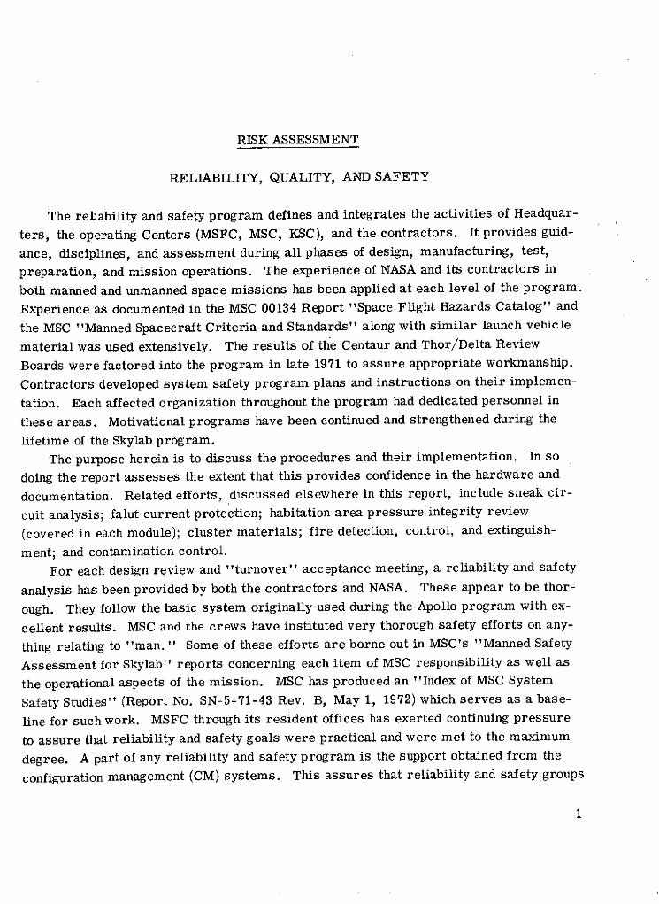
As a result of Apollo experience and the constant pressure to reduce ignition sources
and their ability to reach flammables, a closed trough system was developed to carry all
internal wiring. This is seen in the OWS design. The closed trough system consists of
rigid troughs, flex troughs, interchange boxes, convoluted tubing, and connector boots.
In addition, within these troughs flame barriers have been installed as an integral partof the isolation design to further prevent flame propagation and to cause the flame toself-extinguish. Figures 9 to 11 are indicative of the efforts taken in this design. Testsand analysis indicate that possible ignition source to flammables has been minimized ashave been the flame propagation paths.
26
ORBITAL WORKSHOPCLOSED TROUGH SYSTEM
(GENERAL CONCEPT)
MEZZANINEUPPER FRAME
INTERCOSTAL
STORAGECONTAINER
FIGURE 9
-.J

ORBITAL WORKSHOPRIGID TROUGH
-- COVER- SPLIT GROMMETS(0.025 ALUMINUM)
THERMOFIT NBCG
ERMOFIT SPLIT PARTITIONNB (0.025 ALUMINUM)
RE NTION
0.025 ALUMINUM
ALUMINUM CLAMP(MOLDED FLOUREL CUSHION)
FIGURE 10

ORBITAL WORKSHOPFLEX TROUGH USAGE
(GENERAL CONCEPT)
RIGID TROUGH INTERCHANGE
FLOORGRID
* I' TYPICAL METAL RIGIDPROTECTIVE COVER TROUGH
FLEX TROUGH
FLEXTROUGH
RIGID TROUGH
UPPER H20BOTTLE FRAME
FIGURE 11

Coolanol-15, used as the working fluid in the refrigeration system, could present a
critical crew hazard because of the fire potential and presence of toxic vapor. Extensive
testing and analysis have been reviewed by management in its decision to accept the risk
of using Coolanol-15. Recently, an intercenter Coolanol review team completed an in-
vestigation of all potential problems concerning its use. This included a consideration
of fabrication, quality control, materials testing, training, safety, and overall system
verification of all components and subsystems in the Coolanol loops. It appears to the
Panel that the management systems and their implementation have resulted in adequate
consideration and understanding of the use of Coolanol- 15 and the procedures to alleviate
problems if they should arise during testing and the mission itself.
In the event of a fire during the Skylab mission there appear to be four methods of
effecting extinguishment: (1) fire extinguishers, (2) use of stored water, (3) shutdown of
the atmospheric control system (reduce internal flow or pressure), and (4) shutdown of
electrical power system. The Panel's reviews in this area indicate that shutdown of the
atmosphere control system and electrical power should effectively allow a fire to self-
extinguish. Additionally, fire extinguishers will most likely be used to extinguish the
fire as rapidly as possible to minimize propagation and pyrolysis products. No provi-
sions are known for the use of water directly as an extinguishment aid.
The Apollo fire extinguisher was modified for use on the Skylab vehicle. These
modifications include the design for one hand use and a flare nozzle attachment to re-
duce foam velocity. There are five fire extinguishers onboard the cluster, four of these
in the OWS and one in the AM/MDA. The CSM carries the same fire extinguisher as
used during the Apollo program. MSC, MSFC, and the contractors have conducted com-
prehensive reviews on the subject of extinguisher locations, required volumes, and de-
gradation with storage time. Further studies have covered the crew training procedures,crew translation times in moving from one point in the cluster to another, and the need
and location of access holes in panels and equipment covers. With respect to the crew,
fire procedures are being developed based on when to fight a fire, what to use, and when
to evacuate. The quantity of expelled foam volume of the extinguishers degrades with
storage in a one-G condition. Nominal installation of these extinguishers is made
18 days prior to launch. Concern exists that during that time, as well as during zero-G
storage in orbit the yield of foam may degrade to an unacceptable level. This appears
to be under study at this time, but no resolution is currently known. Fire extinguisher
access holes were to be placed in the AM molecular sieves to accept the extinguisher
nozzle. The status of both items will be noted in the next report.
A more detailed discussion of the crew procedures associated with fire extinguish-
ment and crew protection is included in the MISSION OPERATIONS section of this report.
In summary then, the Skylab program organizations indicate that they have made a
thorough analysis of the fire detection, control, and extinguishment areas, and there is
confidence that those items still open will be adequately resolved.
30

HARDWARE/SOFTWARE ASSESSMENT
MISSION OPERATIONS
Mission operations is a broad category. It includes flight control operations, ground
support systems, crew training programs and associated hardware, crew procedures,
integration of medical operations, MSFC operations support, flight plans, and contin-
gency analysis and mission rules. Mission operations activities are the summation of
hardware performance, flight and ground crew needs and abilities, and the Skylab user
requirements.The Panel centered its attention on the ability of the Skylab program organization
and management systems to achieve intercenter cooperation, needed data flow and under-
standing of hardware capabilities, and realistic planning to translate mission require-
ments into mission ready documentation and mission ready personnel.
The basic documentation of interest to the Panel includes the Skylab Program Direc-
tive No. 43B (March 27, 1972) and the following subordinates: Skylab Operational Data
Book, Skylab Operations Handbook, Skylab Systems Handbooks, Flight Plan, and Flight
Mission Rules.The Skylab Operations Directive 43B is a plans and requirements document. It is
used as the baseline on which program policies and requirements, mission objectives,and mission planning instructions are issued to the implementing Centers. Several
points relevant to an understanding of the mission operations policy need to be clarified.
First, if for any reason the Program Director is unable to carry out his duties for delay-
ing a mission (para. 1.4.2 (8)) it is assumed some other individual must be delegated
this authority. Second, in the same paragraph it is noted that "if a mandatory item can-
not be corrected to permit liftoff within the launch window, . . . has the authority to
downgrade an item from mandatory .. .. and to proceed with the launch . .. " The
possibility of duality in the meaning of "mandatory" may create problems. Last, in
Panel discussions at the NASA Centers on the possibilities of setting priorities for the
experiments the "Flight Scheduling Precedence Number" discussed in this directive
was not mentioned.
The major operations interfaces between MSFC and MSC in developing and imple-
menting operational plans is shown schematically in figures 12 to 15. SOCAR and the
many joint design and operational reviews conducted throughout the life of the program
provided a valuable opportunity to define relationships and assure mutual indepth know-
ledge of the flight systems. Those difficulties that have arisen as to roles and responsi-
bilities in the mission operations area appear to be resolved or are in the process of
resolution at this time.
31

MSFC/MSC INTEGRATION RELATIONSHIPS (TYPICAL)
MSFC MSC
OVERALL MISSION & SYSTEMS REQUIREMENTS (JOINT CONTROL)
MISSION REQMTS DOCUMENT STOWAGE REQUIREMENTS
CLUSTER REQMTS SPEC INTERFACE DOCUMENTS
MODULE/EXPERIMENT Medical,Crew,Flight Ops Reqmts MODULE/EXPERIMENTDESIGN & DEVELOPMENT DESIGN & DEVELOPMENT
Module/Expmts Integ. ReqmtsMEDICAL OPERATIONS
EXPERIMENT INTEGRATIONModule/Expmts/Systems
S CREW OPERATIONSPerf. Capabilities-Constraints
SYSTEMS INTEGRATION FLIGHT OPERATIONS
Crew/Flight Operations Support
JOINT
DESIGN & OPERATIONS
REVIEWS
FIGURE 12

CREW OPERATIONS INTERFACES (TYPICAL)
MSFC MSC
MODULE/EXPERIMENTS INPUT CREW OPS. DESIGN REQUIREMENTS CREW OPS. REQUIREMENTS
REVIEW & CONCUR IN DESIGNDESIGN & DEVELOPMENT
PARTICIPATE IN FLIGHT HARDWARE C/O CREW TRAININGCHECKOUT REVIEW & CONCUR IN C/O PROCEDURES
FMEA'S CREW OPS. HANDBOOKSMAINTAIN TRAINER CONFIG. CURRENT
PROVIDE USE OF ENGRG. SIMULATORS CREW PROCEDURESCREW PROCEDURES
SYS./EXP. INTEGRATION REVIEW & VALIDATE CREWOPS. HANDBOOKS & PROCEDURES FLIGHT PLAN
PERFORMANCE ANALYSISINPUT OPS. REQUIREMENTS/
SIMULATIONS CONSTRAINTS TO FLIGHT PLAN
FMEA'S REVIEW & VALIDATE FLIGHT PLAN
SAFETY C/L'S
FIGURE 13

FLIGHT OPERATIONS INTERFACES (TYPICAL)
MSFC MSC
MODULE/EXPERIMENTS INPUT FLIGHT OPS. DESIGN REQUIREMENTS GROUND OPS. REQUIREMENTS
DESIGN & DEVELOPMENT REVIEW & CONCUR IN DESIGN
CHECKOUT PROVIDE USE OF ENGINEERING FLIGHT CONTROL HANDBOOKSSIMULATORS FOR F/C TRAINING
FMEA'S REVIEW & VALIDATE F/CFLIGHT CONTROL PROCEDURESHANDBOOKS & PROCEDURES
SYS./EXP. INTEGRATION INPUT OPS. REQUIREMENTS MISSION RULESCONSTRAINTS TO MISSION RULES
PERFORMANCE ANALYSESREVIEW & CONCUR IN M/R'S FLIGHT OPERATIONS
SIMULATIONSPROVIDE ENGINEERING & INTEGRATION SUPPOR
FMEA'S DURING THE MISSION
SAFETY C/L'S
FIGURE 14

MISSION OPERATIONS SUPPORT
MISSION OPERATIONS CONTROL CENTER
FLIGHT CONTROLLERS
FLIGHT DIRECTOR
(MSFC) FLIGHT OPERATIONS MGMT ROOM (MSC)
HOUSTON------------------------------------------------------------------HUNTSVILLE
"Problem Solving"
Routine Evaluation of MissionProgress and Systems Performance
HUNTSVILLE OPERATIONS SUPPORT CENTER
OPERATIONS SUPPORT TEAMS:
ELECTRICAL SYSTEMDATA/COMM SYSTEMSTHERMAL/ECS MSFCATTITUDE CONTROL SYS CONTRACTORSCREW SYSTEMSMECHANICAL SYSTEMSCONTAMINATION
I MULATOR CONTRACTOR HOME PLANTS
FIGURE 15
35
The RELIABILITY, QUALITY, AND SAFETY section of this report discusses themanned safety aspects of the Skylab mission operations. Where necessary this area iscovered here.
The major portion of the mission operations work is accomplished at MSC throughthe following organizations: Flight Crew Operations, Flight Operations, Life Sciences,Science and Applications, Safety and R&QA - all of these, of course, under the directionof the Skylab Program Office at MSC. Support contractors tasks pertinent to this areainclude training hardware maintenance, training instruction, systems/operations hand-books, ground support simulations, mission planning, and so on.
Flight Crew Operations
Crew training. - Crew training is the core of achieving real-time mission opera-tional objectives. The effectiveness of crew training concepts and procedures has beenproven on prior manned programs. The Skylab missions are able to take advantage ofthose lessons learned, but there is one disadvantage of no prior "development flights"for SL-2 and only short periods between SL-2 and SL-3, and SL-3 and SL-4. Further-more, all of those things which set Skylab apart from previous manned programs bringan extra burden to bear on the training requirements. Using an astronaut mix of sea-soned veterans with new personnel, the crew training commenced approximately 2 yearsago in the November 1970 period. As trainers became available and mission require-ments better known the specific task training and integrated crew and mission teamtraining began in 1972. Support training was also in fact ongoing throughout the Skylabprogram because of astronaut participation in the design, development, and testingphases. The planned training and hours assigned for each segment are shown in brief intable V. These hours represent the total hours for a crew of three. At this time thepercent of training hours accomplished for the crews is about 60 percent of the total.Training at the KSC was somewhat restrained by the Apollo 17 activities.
Fire/evacuation training for Skylab missions encompasses about 76 hours per man,split between "on-orbit emergencies" and "ground emergencies. " One might questionthe sufficiency of such training to meet the stringent time requirements to move fromany given station in the cluster to another while determining actions to be taken. On theother hand, the many hours of training applied in other areas is often directly applicableto the fire/evacuation effort. This will be discussed further in another part of the report.
The SMEAT and other simulations conducted recently have added immeasurably tothe training of the crews through a better understanding of the workings of the hardwareand the problems involved in their use. There is, of course, the inherent limitation inthe use of nonflight hardware. It may not show up all the little idiosynchrosies of flighthardware.
36

PROCEDURES DEVELOPMENT PROCESS
DATA SOURCES
DESIGN DATA TRAJECTORY FLIGHT CREW
SYSTEMS DATA MISSION REQUIREMENTS TEST DATA
EXPERIMENT MISSION RULES MISSION REVIEWSINFORMATION
OPERATIONAL DATA BOOK CONSUMABLES
DEVELOPMENT PROCESS
SYSTS OPERATIONS PROCEDURES, TIME FLIGHTEXPERIMENTS, LINEOPERATION HANDBOOKS PROCEDURES EXPERIMENTS, PLAN
EVA's DEVDEV DEV
SIMULATION SIMULATION INTEGRATEDAND TRAINING ANALYSES TRAINING AND SIMULATIONS
RESULTS TESTS AND TESTSI II
FLIGHT DATA FILE
SYSTEMS CHECKLISTS LAUNCH, ENTRY RENDEZVOUS FLIGHT PLAN
SYSTEMS DATA BOOKS CREW LOGS
SCHEMATICS EXPERIMENTS OPERATIONS STAR CHARTS
ACTIVATION/DEACTIVATION EVA CHECKLISTS MAPS
SYSTEMS MAINTENANCE GRAPHICS
SYSTEMS REPAIR
MALFUNCTION PROCEDURES
FIGURE 16
37

An area of particular interest to the Panel is that of Skylab cluster housekeeping.
Associated with almost every experiment and most day-to-day operations is the myriad
items of loose equipment and discarded materials that must be accounted for and proper-
ly restowed. Such efforts as the activities scheduling program, crew flight plan, stow-
age in-flight management system, and mission operations planning system are used
in part or totally in the housekeeping effort. Based on the various programs to control
and account for these items, the Panel believes that adequate attention is currently being
paid to this area. This does not preclude surprises in flight. Because of its importance
to the overall operation of the Skylab mission continued attention must be given to house-
keeping.
Maintaining simulation equipment in the in-flight configuration is a continuing prob-
lem. This was a problem encountered and managed on Apollo. Different than the Apollo
program, though, is the very large number of items and experiments that are still under-
going changes, sometimes subtle in nature. The availability of some of the experiment
training hardware appeared to be open at the time of the Panel reviews. The current use
of trainer hardware is of the order of 40 hours per week for the OWS and 20 to 30 hours
per week for the AM/MDA/ATM. This leaves limited time for further modifications or
new requirements.
The crewmen have worked directly into the design, development, test, and operations
areas as the program has progressed. Thus, in addition to the many thousands of hours
of specific training, the crews also are trained through direct familiarization with the
hardware at every phase of its development.
Crew procedures and flight planning. - These activities provide for the organization
of crew time, preparation for contingencies, and definition of training and flight data file
requirements. Figure 16 indicates the process through which procedures and flight
planning are accomplished. The final Flight Data Files are scheduled for completion
about 30 days before each launch to assure the most up-to-date file. The process to
produce these documents has been planned. But the achievement of this schedule is de-
pendent on the resources and the number of changes introduced into the system over the
next few months. This suggests that it behooves the Skylab program organization to re-
strict changed requirements which affect the crew procedures and flight planning to an
absolute minimum consistent with meeting the mission objectives.
Skylab Flight Operations
Flight operations include those activities associated with operational mission plan-
ning and the overall direction and management of flight control and recovery. This in-
volves the implementation of manned space flight network instrumentation requirements,
38

configuration and operation of the Mission Control:Center, and operational evaluation and
testing of landing and postlanding systems. Skylab flight operations have taken into ac-
count the very real differences between Apollo and Skylab and the difficulties imposed by
constrained resource availability. The flight team and ground support system differ sub-
stantially from the Apollo arrangement due to large PI involvement, unmanned mission
phases, and the long duration. They have also considered the Skylab peculiar require-
ment for manned phases, crew time scheduling, and the ability of the ground to monitor
the orbiting vehicle on a less than 100 percent time span.
Mission characteristics affecting flight operations. - Ground system design and the
flight operational requirements for the Skylab mission are affected by the "unique"
character of the Skylab noted previously. In addition, there are such items as (1) the
mass of data to be returned and its analysis, (2) the necessity of real-time flight plan-
ning, (3) no background of development flights, (4) intercenter hardware responsibility
throughout the flight, (5) the housekeeping requirement, and (6) stringent requirements
for the removal of "perishables, " urine and feces samples, as soon after recovery or
splashdown as possible.
Principal investigators. - The PI's form a part of the flight control team. PI mis-
sion support has been placed in four separate support categories:
Category I - PI is present in the MCC during experiment execution. His nonavailability
(or that of previously designated alternate with same capability) is a con-
straint on the carrying out or conduct of the experiment. Currently no
experiments are in this category.
Category II - PI is present in the MCC during conduct of experiment. He performs
analysis of experiment data and makes recommendations for subsequent
experiment operations.
Category III - PI is present in the MCC during conduct of experiment and is available for
consultation. He maintains mission status visibility and provides assist-
ance to flight controllers as required.
Category IV - The PI is not in MCC but is available via telecon for consultation.
The PI's have specific rooms (ATM science room, aeromed experiment room,
EREP room, and science room) assigned for their use. In some cases there appears to
be an underlying feeling discerned by the Panel that there is still a good deal of effort yet
to be accomplished in setting up these arrangements with all of the necessary PI's. If
this is the case, further effort should be extended to make these arrangements as quickly
as possible.
MSFC operations support. - The purpose of the MSFC operations support is stated
39

as "Continue to fulfill the MSFC hardware design/development and systems engineeringand integration responsibility through active support in the operations phase of the Skylabprogram. " Some concerns in this area are discussed in the PANEL REVIEWS sectionof volume I.
MSFC will provide qualified senior personnel to the Flight Operations ManagementRoom and Mission Evaluation Room at MSC while maintaining the Huntsville OperationsSupport Center at MSFC. The concept appears quite sound. With the exercise of goodmanagement and cooperation between the two Centers (MSFC and MSC) the MSFC opera-tional support arrangement should provide a valuable and needed function to assure thesuccess of the Skylab mission. Nonetheless, because there are two Centers separatedby large geographic distances, it would be unusual if operational problems did not cropup from time to time. These must be minimized or eliminated as quickly as possible.
Flight control training, documentation, and schedules. - The Flight OperationsDirectorate at MSC published an integrated training plan in October of 1971 defining thetypes of training, the certification program for each flight controller, and the trainingfor non-Flight Operations Directorate personnel working in support of the basic team.It was interesting to note that videotapes of the classroom sessions were being made toallow additional sessions to be held with new personnel and to refresh the baseline groupsas required.
Based on the data presented it appears that much of the training has yet to be ac-complished.
Flight control documentation posture was indicated to the Panel as follows:
Document Preliminary document Final document
Systems Handbooks Complete March 1973Mission Rules Complete February 1973Flight Control Operations October 1972 February 1973
Handbook
Branch Console Handbooks October 1972 April 1973SL-1 Operations Handbook October 1972 March 1973Command Procedures Handbook September 1972 February 1973Branch Photo Support Albums -------------- October 1972
Flight control manning plan. - The personnel assigned to the various operationsactivities, as to type and numbers, is crucial to the success of the MSC operations andefforts and is currently under review. The reason for the difficulty in selecting thenumber of teams and their mode of operation appears to stem from the smaller numberof flight controllers and support personnel available and the cost of ground system hard-ware. This is not just a function of the current economic posture but is due to the re-quirement for continuous operations for 8 months versus 2 weeks for the Apollo mis-
40

sions. It has been indicated that the optimum number of mission operations teams
would be five. Due to the practical aspects this cannot be achieved. The question now
revolves around whether there should be three or four teams. From the material re-
viewed by the Panel, four teams seems most logical. It allows for a reasonable amount
of sick time and leave time for the team members, whereas the three team system does
not. It is estimated that 207 people will form a flight control team with specialty per-
sonnel used as needed, for example, when retrofiring and recovery. Of these 207 all
will be NASA except for 50 to 60 contractor specialists. The number of "new" people,
that is, those who have never sat at a console before, will be quite large - as high as
60 percent of the total. This, of course, is a further reason for the detailed and ardu-
ous training program envisioned by the MSC organization. Obviously, manning re-
quires further study, and quickly at that, to assure that the personnel with their adequate
training are available for the initiation of the Skylab major flight simulations and actual
mission.
Ground support systems. - The Skylab ground support equipments includes both
hardware and required software. The following differences between the Apollo and Sky-
lab program are indicative of the new requirements that had to be met:
(1) Noncontinuous real-time data retrieval
(2) Continuous data recorded onboard and dumped during periods of real-time com-
munications
(3) Greater variety and extent of data to be communicated up-and-down link
(4) Longer duration of support required
(5) Experiment activity to flight test activity far greater on Skylab
(6) Extent of experiments interaction with space vehicle power, ECS/TCS, vehicle
attitudes, and orbit position
As a result of these new requirements the ground support systems have been de-
signed to provide greater system reconfiguration flexibility and to require minimum time
for preventative maintenance. In addition, the equipment should also provide data more
directly to the users and eliminate remote site tape handling and shipping. It has been
indicated that the deliveries of portions of ground equipment have slipped in schedule and
that the mission simulations that were to have started in September may slip over into
the November-December time period. This, combined with the obvious impact of sup-
porting the Apollo 17 launch in December 1972, will require greater emphasis and effort
on the part of both management and working flight controller personnel over the next few
months. The reason for the Apollo 17 constraint is that some 50 percent or so of the
people will come from there and obviously can work only one program at a time. The
communications and telemetry network for Skylab (STDN, NASCOM) appear to be in good
shape. Some areas are still under discussion to resolve minor problems. These in-
clude the use of ARIA (Apollo range instrumented aircraft) to support the Skylab and
41

scheduling of site usage during the 8-month Skylab mission due to other vehicles onother missions.
To support Skylab requirements the following validation and test and checkoutschedule was instituted:
Test description Estimated completion dates
Mission control center internal validation tests:
With mission operations computer November 18, 1972With real-time computer complex software December 1, 1972
MCC external validation tests:
With Merritt Island area February 1973With worldwide network April 1973
Goddard network readiness test April 1973MCC simulations readiness test November 1972MCC pad readiness date November 1972MCC/network simulation January 1973Network on mission status April 1973
Medical operations. - Medical operations support is provided for the preflight, mis-sion, and postflight phases. The Mission Control Center medical team is formulated asshown in figure 17. Planning and documentation in this area appears to be progressingsatisfactorily. Yet, as noted in the Panel's preliminary report contained in the ThirdAnnual Report to the Administrator, there still appear to be some problems with staffingfor medical support. This, though, is under continual study and it is hoped that the prob-lem will be resolved in the near future.
Fire evacuation procedures. - Fire in any location of the Skylab cluster is a criti-cal crew hazard requiring immediate and correct response from the crew. As a resultof fire location, materials, and extinguisher studies, crew procedures have been pre-pared and to some extent tested through crew/equipment simulations. Procedures asso-ciated with the onset of fire warnings or known fires on board the vehicle are based onthe philosophy that the crew should always move toward the command module obtaininglife support and fire fighting equipment enroute. The fire is to be fought only if it blocksthe route to the command module, is visible, and can be assessed as containable. Theprime concern is crew protection rather than equipment protection or mission continua-tion.
42

MISSION CONTROL CENTER MEDICAL TEAM
FLIGHT
I- MEDICAL> MANAGEMENT
BOARD
EXPERIMENTPRIORITIES
EXPERIMENTS EXPERIMENTS EXPERIMENTS MEDICAL TEAM LEADER PANELOFFICER OFFICER OFFICER SBYTM
FOR FOR FOR COMMON FUNCTIONS OF MO'SEREP ATM MEDICAL ANDCORRELARY MEDICAL OFFICER MEDICAL OFFICER MEDICAL OFFICER
FOR FOR FORCREW HEALTH EXPERIMENTS SYSTEMS
OPERATIONAL PRINCIPAL BIOMEDICAL ENGINEERS DATA HDN
CONSULTANTS COORDINATING SCIENTISTS CLERICASTF
171 092093 131 133 151 070-S 110'5
41 R 0.,PROEC i
PRINCIPAL INVESTIGATORS EN ERS
FIGURE 17

As the crew moves toward the CM the procedures indicate they should respond asfollows if possible:
Obtain fire extinguisher.
Obtain oxygen mask.
Obtain suit.
Locate and assess fire.
Shut off power to fire area.
Shut off fans.
Shut off coolant loops in fire area.
Enable Manned Spaceflight Network (MSFN) control.
Break fire propagation paths.
Fight fire.
Remove atmospheric contamination if fire is extinguished.Space suit availability for crew emergencies and crew translation times has received agood deal of study and testing to assure that the maximum protection is afforded thecrew in case of emergencies. Based on the material presented to the Panel and thatprovided through reports it appears that the current procedures for evacuation and firefighting are acceptable and should provide a good measure of confidence in the systemthat provides guidance and requirements.
In April 1971 the Safety Office at MSC completed "Skylab Orbital Assembly FireStudy" (MSC-04048, 1971) which covers the following overall aspects of fire protection.Fire prevention requires emphasis on housekeeping aspects of flammable materials con-trol. Those systems using Coolanol-15 are to be monitored to assure their continuingacceptability. Fire detection requires acceptable fire sensor tests and maintenanceprocedures, coverage, maintenance, and replacement capability. These appear to havebeen accomplished.
Skylab space rescue. - Although rescue is covered to some extent in the RELIABIL-ITY, QUALITY, AND SAFETY section of this report, it may be well to explore further togather greater understanding and consequently more confidence.
In the Mercury and Gemini programs, the spacecraft could not be used for rescuebecause of their restricted size and life support capability. A different and unique space-craft would have been necessary to retrieve stranded astronauts. In the Apollo program,rescue capability was again not feasible because of the limited life-support capacity ofthe lunar module coupled with the time required for the CSM to travel from Earth to theMoon. A rescue vehicle standing by in lunar orbit would have been necessary for lunarorbit rescue but still could not pick up astronauts on the lunar surface.
With Skylab, the orbital workshop offers long-duration life support in Earth orbitand a practical rescue capability is feasible. In each of the three Skylab visits, theastronauts fly to the space station in a modified Apollo CSM. It is then powered downafter docking, but remains available for life support and crew return in the event of
44

cluster failure. Therefore, the only failures to be considered for rescue requirements
are the loss of CSM return capability or the loss of accessibility to the CSM. In this
event, a second CSM would be launched carrying only two men with room for the three
astronauts to be picked up in orbit, and the rescue CSM would then return with a crew of
five. Therefore, after each of the first two manned launches, the next vehicle in normal
preparation for launch would be used for rescue if needed. After the third and final
launch (SL-4), the Skylab backup vehicle would be made ready for possible use as a res-
cue craft.
Just how long the Skylab astronauts would have to wait for rescue depends on the
point in the mission when the emergency develops. The wait in the well-supplied orbit-
ing cluster could vary from 48 days to 10 days. If, for instance, the need for rescue
arose on the first day of the Skylab's occupancy or reoccupancy, present plans indicate
that it might take 48 days for the launch crews to ready the rescue vehicle. This would
include approximately 22 days to refurbish the launch tower following the previous
launch. During this period the rescue kit or modification hardware would be installed in
the CSM. The entire vehicle would then be moved to the launch pad for launch requiring
about a week.
The later in a mission rescue is needed, the sooner the vehicle would be ready for
launch. The response time from the "rescue alarm" to launch is reduced to about
28 days and 10 days at the end of the first and third missions, respectively.
Providing rescue modes for all conceivable emergency situations would obviously
require instantaneous response. This is a capability not practical or feasible with the
present space vehicle because of the preparations mandatory for a successful launch.
Based on the material presented to the Panel during the reviews the projected rescue
techniques for Skylab appear to cover the most likely emergency situations.
ASSESSMENT OF MISSION OPERATIONS
Activities associated with mission operations planning and implementation appear to
be proceeding satisfactorily. The schedules are admittedly tight and the resources
limited. At this point in mission planning there are naturally a number of items of po-
tential impact:
Clarification of the Skylab Operations Directive No. 43B, paragraph 1.4. 2. (8), on
delegation of authority for scrubbing missions and the meaning of the term "mandatory"
is necessary. These may become more significant as the launch time grows near when
all possible areas of misinterpretation should be minimized.
The continuance of open lines of communication is needed between the NASA Centers
to assure understanding of their respective roles and responsibilities during the mission.
45

Flight crew operations:
Defining realistic Skylab cluster housekeeping
Limitations of nonflight hardware during training, particularly experiments
Limited availability of hardware for training
Control of program changes (hardware/requirements) and their impact on crew
procedures and flight planning
Flight operations:
Ability to integrate the PI's into the mission
Ability and adequacy of flight control documentation
Personnel staffing limitations
Deliveries of needed hardware and software for ground systems support
COMMAND AND SERVICE MODULE
Because of mission differences, duration, and fixed attitude constraints of the Skylab
program, several major modifications had to be made in the CSM's allocated for the
Skylab program. The CSM's were modified to accept electrical ppwer from the work-
shop. One of the three power-generating fuel cells on the CSM was deleted. Three bat-
teries were added to the SM to provide power for descent from the workshop since the
cryogenic reactants that power the fuel cells will have been depleted during its long
Earth orbit stay. Two of the four service propulsion system propellant tanks and one
helium tank were not required for the missions and so were deleted. A propellant stor-
age module was incorporated into the SM to increase the quantity of reaction control sys-
tem propellants, thus enhancing in-orbit attitude maneuvering and providing a backup
method of deorbit propulsion.
The caution and warning system was modified. The warning tone was carried to the
workshop to allow the entire crew to pursue activities in the OWS and still monitor the
CSM.
The CSM audio system was hard-lined to the OWS and will serve as the communica-
tions center for the workshop. Stowage provisions in the CM have been vastly increased
to allow for the greatest degree of resupply as well as return of experiments, film,biological samples, and other needed material. The thermal control system was signifi-
cantly modified to meet the requirements of the fixed attitude dictated by the workshop
cluster and the need to minimize condensation within the CM while maintaining CSM com-
ponents and propellants within allowable temperatures.
A tank was added to the SM to allow water generated by the fuel cells after docking
to be stored rather than vented overboard. An overboard hydrogen dump system was
incorporated into the SM cryogenic system to allow maintenance of the hydrogen tank
46

pressures within safe limits after the fuel cells are shut down. A nonpropulsive vent
was used. A similar nonpropulsive vent was installed in the CM hatch to allow venting
of surplus oxygen. These vents were necessary and the material ejected through them
has been examined for contamination of experiments.
CSM vehicles designation and their assignment to the Skylab missions are CSM 116
for SL-2, CSM 117 for SL-3, CSM 118 for SL-4, and CSM 119 as a backup and rescue
vehicle if required. A contingency modification kit for converting a Skylab CSM to a
rescue vehicle in the event a crew becomes stranded in the workshop is also being pro-
vided. The rescue kit could be installed in any of the Skylab CSM's. Further informa-
tion on the rescue plan is discussed in the RELIABILITY, QUALITY, AND SAFETY sec-
tion.
SLA 23, 24, 6, and 25 go with CSM's 116, 117, 118, and 119, respectively. All of
these SLA's are in storage at KSC.
The rescue vehicle kit components consists of -
Two aft bulkhead mounted crew couches
Two oxygen umbilicals and hose connector assemblies
Two oxygen masks and hose connector assemblies
Two crew communications umbilicals with cables and connectors
Crew equipment and stowage items to support additional crew
Ballast for required center of gravity
Postlanding vents and associated air ducting assemblies
Experiment return pallet assembly
Probe and drogue modifications
All of these items, along with modification instruction documents, are placed in bonded
storage at KSC and are to be made available if required.
The rescue kit has been verified. Fit and function will be checked at KSC.
Since the Skylab CSM's constitute a modification to the very successful Apollo CSM's
and the contractor appears to be maintaining adequate skills and engineering capability,
there is a high degree of confidence in the CSM's capability to do their job. Apollo
anomalies that apply to the Skylab CSM's are being resolved on the same basis as was
done for the Apollo program.
The following discussions of the individual major onboard systems is intended to
point out the activities which provide confidence in the system and those areas requiring
closure.
Thermal Control System
In general, the approach used to verify the capability of the thermal control system
involved the construction of a transient computer program. Using the essentials of the
47

Apollo program, the computer program predicts the temperatures and temperature
transients experienced for any given sequence of mission events. It also verifies thepredicted responses through exposure of a full-scale vehicle in thermal-vacuum testchamber. In addition, it defines mission constraints, and provides them for incorpora-tion in mission rules and operational handbooks. While the CM shows adequate margin,the SM shows that only a small margin exists in some "worst case" conditions. Thereappears to be no concern here based on the material presented to the Panel.
Environmental Control System
In conjunction with the thermal control system, the environmental control system
(ECS) provides the flight crew and electronic equipment with a conditioned atmosphere.The ECS is operated continuously during undocked mission phases. Except for the pri-mary glycol system, it is shut down during docked operations in orbit. Apollo flightexperience has indicated a high degree of reliability under similar flight conditions.For instance, the secondary coolant loop has been operated during boost, deactivatedfor the entire mission, and reactivated prior to reentry. The major portion of the ECSwas subjected to an augmented system Skylab mission test. The test was designed todemonstrate the performance of the ECS during several mission simulations with normaland off-limit conditions. Approximately 1500 hours of testing were accrued. A furthertest of 120 days under a quiescent mode of operation similar to that occuring while theCSM is docked to the cluster was conducted. Maintenance of wall surfaces above thedewpoint temperature to preclude condensation appears to have been a problem. ThePanel understands that condensation has been minimized by system control set-pointsbut is still not clear on whether the condensation that is predicted to occur during dockedcondition will or will not cause problems which have yet to be resolved. During groundoperations prior to launch the GSE must also be capable of precluding the formation ofcondensates. With respect to SM, thermal control tests were conducted to assure ade-quacy of current paint system as a result of paint blisters observed during CSM 112 EVAon Apollo. The closure of this potential problem will be noted in the next report.
Structural Systems
Changes to the Apollo configuration caused by the deletion of CM handholds andhandrails, repositioning of support structures, and deletion of various portions of on-board systems and their impact on structural adequacy were checked by a combinationof structural analysis, similarity with previous vehicles, and extensive testing (particu-
48

larly for the SM which had far more structural changes). There appeared to have been
few problems surfaced by these tests.
Mechanical Systems
The only mechanical system item requiring modification for the Skylab mission was
the uprighting system. The uprighting system places the command module in a stable
position upon Earth landing. The system consists of three air bags with their associated
inflation and retaining hardware. The Skylab system differs from the Apollo in that the
two intakes for the air used to pressurize the bags are interconnected in such a way that
if one intake is submerged a water trap allows the onboard compressors to continue
operating at full output. This system was successfully tested and no further problems
were encountered.
Stowage and Crew Equipment
Skylab CSM stowage capability has been revised to support orbital workshop opera-
tions with particular attention to increasing the volume available for storage. Crew
equipment additions involved are fire extinguisher, optical alinement sight mount, re-
turn mission water provisions, and tie-down straps. Crew compartment fit and function
(C2F 2 ) tests and other tests and analyses indicate no significant problems.
Service Propulsion System
The service propulsion system provides the impulse for X-axis velocity changes
throughout a mission. It also provides the service propulsion system abort capability
after the launch escape tower is jettisoned. The Skylab mission requires less helium
and propellant than the Apollo missions. Therefore, one helium storage bottle and the
propellant storage tanks were removed from the Skylab spacecraft. As a result of the
extended duration Earth orbit in a fixed attitude (docked), an active thermal control
system is required to maintain system temperatures. As presented, the verification
program indicated few problems and these appear to have been resolved.
49

Reaction Control Systems
Skylab, like Apollo, has two separate reaction control systems, one set for the CM
and one for the SM. The CM system is essentially unchanged from the Apollo while the
SM system was supplemented with an additional 1500 pounds of stored propellant. There
appear to be no open items in these systems.
Electrical Power System
The Skylab EPS conditions and distributes power to the CSM during its docked mode.
During independent operation the CSM derives its power from fuel cells and batteries
depending on the segment of the mission. Through the SOCAR and the DCR system the
electrical power systems of the CSM and the cluster have been verified as being com-
patible. This included that time period during which both the EPS' would be operating in
parallel. Parallel operation occurs during the beginning and end of each Skylab mission
segment and is estimated to be no more than 4 minutes each time. MSFC, MSC, and
contractor studies were conducted to assure this point. The descent battery cases
cracked after qualification vibration testing. As a result of this, the cases were
strengthened and internal changes made. The results of retest of these improved bat-
teries has not been seen by the Panel. The nonpropulsive vents used to vent the hydro-
gen and the oxygen were discussed, and it appears that only the hydrogen vent was tested
to assure its adequacy. The oxygen vent was assumed to work on the basis of similarity.
One could question the validity of such an assumption since the working fluids are dif-
ferent. A clarification of this will appear in the next report.
Displays and Controls/Caution and Warning Systems
The displays and controls provide an integrated arrangement of like functions to
control and monitor the various operational systems. The caution and warning system,
which is included in the displays and controls, provides a means by which the crew re-
ceives a timely alert to actual or potential CSM system failures or out-of-tolerance
conditions. The unchanged and modified displays and controls were verified compatible
with the Skylab mission by similarity with demonstrated Apollo performance. The new
items, not similar to Apollo, were verified by qualification tests and supported by
analysis. There appeared to be no major problems in these systems.
50

Communication System
The communication system equipment and configuration are identical to those of the
basic Apollo. It is augmented by a speaker box and configuration changes to facilitate
cluster operation. The unique Skylab requirement is again in the extended operating
time for a portion of the communications system. This includes the audio center,
unified S-band equipment, premodulation processor, and up-data link. These units all
use solid-state devices, having 100 percent derating, and preusage burnin screening as
well as equipment burnin of 100 hours. Based on this justified extrapolation of pre-
viously demonstrated operating life to meet Skylab requirements was possible.
Ordnance Systems
Of the numerous devices used on the CSM, the Panel's interest centered on the
CM-SM separation system. This system is located external to the CM and between the
aft heat shield of the CM and forward bulkhead of the SM. CM separation from the SM
takes place during all abort phases and after orbital flight before CM reentry. The
Apollo RDX type tension tie cutter did not pass the Skylab thermal vacuum verification
test. Detonation energy available for cutting was low. The RDX was replaced with a
HNS silver sheathed shaped charge. At the time of Panel review the replacement was
undergoing test certification. Failure of the tension tie cutter to separate the CM and
SM is critical, and a qualified tension tie cutter must be available. The closure of this
item will be enclosed in the next report.
Based on the material presented to the Panel, management controls are still in
effect to assure hardware of high quality.
ORBITAL WORKSHOP
Background Description
The orbital workshop is a two-floor structure providing accommodations for the
crew and a primary experiment area. The first floor is divided into four sections: the
sleep compartment, the waste management compartment, the wardroom, and the experi-
ment work area. The biomedical experiments are performed in the experiment work
area. The second floor is devoted primarily to experiments which require relatively
large volumes or which use either of two scientific airlocks for external viewing or ex-
posure. The remainder of the space is occupied by subsystem and storage compart-
ments. These arrangements are shown in figures 18 and 19.
51

AccessPort
LightFixture
Food Freezer StorageCompartments
Heater FanAssembly
Waste ManagementCompartment Fan
Solar Array SystemBeam Fairing
SleepCompartment
WasteManagement
Compartment
WardroomFood Management
WasteDisposalAirlock
Solid WasteCollection
Screen
WasteDisposal
Tank
Solar ArrayWing Section
Radiator
FIGURE 18 - ORBITAL WORKSHOP
52
ORIGINAL PAGE ISOF POOR QUALTry

Cabin AtmosphereDistribution Ducts
WaterTanks '
StorageLockers
FilmVault
Second Floor
ExperimentArea
ScientificAirlock
CompartmentDivider GridStructure
Bio-MedicalExperimentWorkArea
ThrusterGasSupply
FIGURE 19 - ORBITAL WORKSHOP
53OIGINAL PAGE IS
OF POOR QUALITY

The workshop also is the storage area for crew supplies, such as food, water, and
clothing, as well as providing for personal hygiene and waste and trash disposal.
The OWS is an S-IVB stage of the Saturn V launch vehicle that is ground outfitted
to be suitable for manned habitation.
The OWS structure provides for
1. Habitable environment with crew provisions and consumables
2. Capability for experiment installation
3. Support for conducting experiments
4. Propulsive capability for attitude control
5. Solar array power source, mounting provisions for the array, and routing of
power to the airlock module
6. Storage for cluster waste material
7. Capability for orbital storage and reuse
8. Two scientific airlock installations, one on the cluster -Z axis (Sun side) and one
on the cluster +Z axis (dark side)
9. Capability for television transmission via MDA video selector and CSM transmitter
10. No scheduled or planned activity requiring access into the habitable volume of
OWS after closeout in the Vehicle Assembly Building
For launch, the OWS consists of an S-IBV/S-V forward skirt, S-IVB propellant
tanks with preinstalled crew and experiment accommodations, and an S-IVB-S-V aft
skirt and interstage. The forward skirt interfaces with the IU, the forward tank dome
interfaces with the AM, and the aft interstage interfaces with the S-II stage. The in-
orbit configuration is essentially the same. The only changes are that the interstage
separates with the S-II stage, and the solar array and meteoroid shield are deployed.
Significant changes to the S-IVB structure have been caused by Skylab require-
ments. Provisions have been made for an OWS vacuum outlet, scientific airlock (SAL),
and attachments for crew quarters, experiments, and equipment stowage. A waste dump
airlock has been provided in the common bulkhead area for disposing of wet and dry
waste through the common bulkhead from the LH 2 tank to the LOX tank.
A meteoroid shield is designed as a structurally integrated part of the OWS and
protects the cylindrical portion of the tank. After deployment, the shield extends about
6 inches radially from the outer surface of the LH 2 tank. Deployment is accomplished
during orbit by a signal from the IU.
The S-IVB is divided into a two-level crew quarters by a structure serving as a
floor/ceiling installed in the LH 2 tank, perpendicular to the longitudinal axis of the
S-IVB stage. The section aft of the floor/ceiling provides the crew with accommoda-
tions for sleeping, food and waste management, hygiene activity, off-duty activity, data
management, and the implementation of corollar experiments.
Astronaut mobility/stability aids have been installed to assist the astronauts in
performing tasks associated with activation, crew habitation, experimentation, and de-
54

activation. These aids are of two basic types - fixed and portable. Fixed astronaut
aids include handrails, tether attach devices,, and the central handrail. They are per-.
manently installed in locations throughout the LH 2 tank where it is expected that heavy
traffic or task loading will occur. Portable astronaut aids include handholds, tether
attach brackets, and foot restraints,
OWS interior.lighting allows for crew equipment installations, normal and emer-
gency crew activities, and experiment operations. The interior lighting system con-
sists of initial-entry lights, general- illumination- lights, emergency lights, and special-
purpose lights.. Orientation (running) lights are provided for determining the gross
attitude of the passive vehicle and movement relative to a line of sight through the win-
dow of the docking vehicle. In addition, -white floodlights will be used to illuminate the
exterior of the cluster and the exterior of the AM within the thermal curtains,. A port-
able floodlight is. used by the astronaut. during EVA.
The subsystems comprising the total OWS include the following for our purpose:
Panel examined in detail Panel made cursory examination
Structures subsystem . Thruster attitude control subsystem
Environmental and thermal control sub- Solar array subsystem
system Ordnance subsystem
Electrical power -subsystem - (EMC and Ground support equipment subsystem
corona) -
Communications and data acquisition system
Caution and-warning subsystem
Habitability support subsystem
Crew equipment subsystem
Three systems were reviewed ohnthe following occasions: (1) MDAC-West, October
1971, (2) Marshall, April 1972, (3) PDTR, April 1972, and (4) DCR, October 1972.- - The
Panel in its factfinding was interested in the evident effectiveness of the technical man-
agement systems, the maturity of the design, and the quality of the hardware. The
following discussion is based on these factfinding reviews.
Note should be made that experiments and other modules are discussed here only as
they present interface requirements. They are Idiscussed ii detail elsewhere.
Orbital Workshop Hardware -
The OWS flight h'ardWare checkout began November 6,: 1971 with the start of
continuity/compatibility testing. It continued through completion of the all systems test,
electro/magnetic compatibility test, and residual subsystem retests August 16, 1972.
55

During this period, all subsystems, crew compartment fit and function (C 2 F 2 ), and thecombined all systems test and electro/magnetic compatibility (AST and EMC) test wereperformed.
The crew compartment fit and function was conducted in two increments. The first
increment ran May 22 through 28, and the second increment August 12, 1972. Some
C2F 2 checkout remains to be accomplished at KSC primarily because of lack of hard-
ware, notably in the stowage area.
The combined AST and EMC test was performed July 17 through August 7, 1972.
This test functioned each OWS system on a simulated prelaunch, launch, and orbital
time line to verify systems compatibility throughout the mission profile.
Further checkout activities included a mercury certification of the habitation areaand calibration of the meteoroid shield strain gages. Major manufacturing activity
focused on modification of the meteoroid shield and cleanup activities associated with
final inspection. The spacecraft was moved to Seal Beach for thruster attitude control
system proof testing on August 31, 1972. Final preparations for shipment followed atHuntington Beach.
Problems encountered during this checkout were documented on test problem re-ports. A summary of the closeout status of these reports is shown in table VI. Sometest problems could not be closed at Huntington Beach because of unavailable hardware
and unfurnished rework and testing. These are transferred to a recap test problemreport which identifies the problem being transferred to KSC, the reason the problem
was not resolved at Huntington Beach, and the applicable documentation (i. e., failurereport, discrepancy report, inspection item sheet, original test problem report).
The retest outline is the document that identifies, at the time of shipment, open re-test and/or test requirements of incompleted assemblies, discrepancy reports, failurereports, and removals and requires quality assurance verification for final buy-off. Itcontains three categories:
(1) Retest required as a result of assemblies, failure reports, discrepancy reports,and removals that were worked after factory testing
(2) A listing of unworked assembly outlines, engineering orders, etc.
(3) A line item to identify the recap test problem report and associated test or retest
requirements that must be transferred to KSC
All items associated with open work are listed in the data package contained as apart of the certificate of flight worthiness and DD250 form.
There were 27 OWS design certification review (DCR) review item discrepancies(RID's). Essentially all are closed at this time.
All test objectives have been satisfied except those noted in table VII.
56

Orbital Workshop Structures Subsystem
The OWS structures subsystem consists of the following major components:
1. Forward skirt which serves as structural continuation between OWS habitation
area tank and the IU. It provides space for mounting electrical and electronic equip-
ment as well as providing support for the solar array system wing assemblies. There
appeared to be no unique fabrication techniques or new technology applied here. The
major items requiring assurance were the SAS attachment provisions which support
these most important electrical power generating components. At the time of the formal
DCR there were no open items, waiver, or deviations associated with the forward skirt,
and it complied with the MSFC hardware safety checklist. McDonnell Douglas-West
expects little or no work to be done at the KSC on this item.
2. Thermal shield. The thermal shield, attached to the aft 34 inches of the forward
skirt, functions as a radiator barrier to aid in stabilizing the habitation area tempera-
ture. There appear to be no constraints to mission or crew safety attached to this item.
3. Aft skirt and thermal shield. The aft skirt is a modified Saturn V/IVB aft skirt.
Structural capabilities apparently were not changed by OWS modifications. The attach-
ment of the aft thermal shield is similar to that for the forward thermal shield. This
skirt also has attachments to support the SAS installation. The OWS flight loads are
indicated as lower than those for the S-IVB aft skirt and there was no indication of any
problems. During development of this structure, the thruster attitude control subsystem
nozzles which are hard mounted to this structure had to be modified to a shock-mount
to preclude damage to nozzle valves. Analysis and test results show no waivers or
specification deviations required.
4. Aft interstage. This is a frustum-shaped assembly which transmits loads be-
tween OWS aft skirt and S-II stage and provides the OWS radiator assembly protection
during launch. It remains with the discarded S-II stage. There appear to be no con-
straints caused by this item.
5. Thrust structure. This is a multipurpose structure using the basic S-IBV stage
with modifications to support the thruster attitude control subsystem's nitrogen gas
storage spheres and associated piping, the subsystem's meteoroid protection shield,
and the refrigeration system radiator with its impingement shield and structural sup-
port. Some items of note are the single failure points associated with the thruster
attitude control system.
(a) Rupture or bursting of the thruster attitude control subsystem's storage and
manifold could jeopardize the safety of the crew.
(b) Radiator shield actuator assembly release mechanism failure could preclude
jettison of radiator shield adversely affecting OWS thermal control system opera-
tion.
57

These single failure points appear acceptable based on the added manufacturing and
quality controls imposed, tests and analysis conducted, and similarity to prior use on
Saturn launch vehicles.
6. Meteoroid shield. This shield for the habitation area is composed of cylindrical
sections. When deployed they act as the outer barrier with the OWS main tank wall as
the inner barrier. The standoff distance of this meteoroid shield is approximately
5 inches. It is deployed on-orbit by severing tension straps with expandable ordnance
tubes and moved outward by 16 links powered by independent torsion bars.
Meteoroid shield deployment was successfully demonstrated at NASA/MSFC. How-
ever, during pressure testing one of the shield hinges failed structurally. The hinge
subsequently was redesigned and the strength capability verified by tests. These de-
sign changes have been incorporated into the OWS. The static test article (STA) is to
be reworked and retested at NASA/MSFC during the October to November time frame
and these test results should be verified.
Verification of the structures subsystem was demonstrated by the satisfactory com-
pletion of all subsystem testing.
A further deployment production acceptance test is expected to be conducted atKSC.
7. Habitation tank. This "habitation or crew area" consists of a forward dome,main cylindrical section with window and door openings, and an aft common bulkhead
forming the "lower floor. " The interior is insulated with polyurethane foam coveredwith an aluminum foil-fiberglass-teflon type liner. In addition, the external surface ofthe forward dome is covered with insulation consisting of some 95 layers of aluminized
mylar with interspersed layers of separator sheets, while the cylindrical portion iscoated with a reflective coating.
The Panel's interest here was the structure's ability to support onboard equipment
particularly through the SL-1 launch period and to maintain onboard pressure within the
allowable atmospheric gas leakage (OWC decompression). The allowable leakage ratehas been set at no more than 5 pounds mass per day in orbit. Table VIII indicates the
expected leakage allowances for hatches and penetrations. In line with this approach the
Panel identified the following areas which are discussed here:
1. Scientific airlock. It is used with experiments S-063 and S-190B. The scientific
airlock provides vacuum source and allows deployment of experiments outside the
habitation area. There are two ports, one on the solar side and one on the anti-solarside.
2. Forward dome entry hatch. It is located at the apex of the dome and providesfor workshop entry in orbit. It functions as a structural part carrying pressure loadsduring boost.
3. Side access panel. It provides ground access into the OWS module for installa-tion and work on such items as experiments, water containers, food containers, etc.
58

4. Wardroom viewing window. It is of a double pane construction approximately
18 inches in diameter to allow simultaneous viewing by two crewmen. The design in-
cludes thermal and meteoroid protection when not in use.
5. Trash disposal airlock. It is a passthrough chamber built into the waste tank
common bulkhead. A failure poses both a potential pressure loss and microbial con-
tamination problem.
6. Water bottles and stowage container support structure. It provides for large
mass loads subject to static and launch acceleration loads. This is a good representa-
tion of all such structural loads.
The scientific airlock has a window which is the refurbished Apollo window and its
failure, as with the scientific airlock doors, would jeopardize the safety of the crew.
The inboard face of the scientific airlock has an opening which can be sealed by an ex-
periment or a window cover. Because of this the Panel feels that procedures for both
flight and ground operations must be explicit in the use of the scientific airlock. For
example, flight procedures should specify that the crew must be certain that the experi-
ments are indeed tightly situated against the scientific airlock to preclude leakage as the
experiment becomes a part of the airlock pressure vessel.
Since the inner and outer surfaces of the assembly have highly effective antireflec-
tive coatings, special care is required during ground operations.
The low temperatures on the anti-solar side made a desiccated repressurization
necessary to preclude humidity problems. Recent authorization for this resulted in a
new design which is still undergoing qualification tests. These are scheduled for com-
pletion in November and to date indicate no problems are expected.
Precise alinement of the individual scientific airlock is apparently difficult because
of deflections due to thermal, gravity, and pressure environments. Alinement must be
done at KSC.
KSC is aware of the measurement work which they have to accomplish. In reviewing
the scientific airlock structure it appears that it is capable of meeting its design re-
quirements.
However, an item to be noted is that some scientific airlock components were made
from material which had relatively low stress corrosion threshold levels. Stress cor-
rosion analysis indicate susceptibility of the scientific airlock's aluminum 2014-T652
housing and aluminum. The 2024-T4 supports will possibly experience stress corrosion
cracking, but since the housing and struts will be under a compressive load, the cracks
should have little impact on the scientific airlock's operations. It was indicated that if
cracks develop to the point where leakage occurs the scientific airlock integrity could
be maintained with the outer door closed. There is also a possibility of closing any such
leaks by using aluminum pressure sensitive tape or polybutane sealant putty indicated
as part of OWS in-flight kit.
59

Subsequent to the completion of the forward dome entry hatch a rodent bearing
failure during vibration was discovered. The failure apparently did not affect operation
of the hatch. Failure analysis is still continuing; indications point to the cause being an
improperly adjusted link (human error). Inspection of the spacecraft links is scheduled
during subsystem checkout at KSC. A further check will result from integrated checkout
requirements which specify a functional test with 25-pound maximum handle loads. If
the hatch does not operate properly, tools are available in the tool kit. Procedures and
tools have been verified on the test hatch. Leakage through the hatch seal has been ana-
lyzed. Prior proven application materials and special controls indicate that it is an
acceptable single failure point.
Based on the analyses and test results presented to us, the side access panel as
well as the opening into which it fits are structurally adequate. Tests indicate that no
excessive leakage problems.
Two leakage problems were encountered. They were the wardroom window cover
and the SAS wing cavity. Both are currently being redesigned and are identified as open
work at KSC.
The protective cover leakage exceeded the allowable rate. Window redesign incor-
porates an O-ring seal in the cover plate (discussed subsequently) as well as on the sup-
port ring and window frame. When complete this will be installed and tested at KSC.
With regard to the viewing window installation, the only major problem encountered in-
volved the type of vent system used to vent the cavity between glazings to relieve the
pressure. When the vehicle is launched, the cavity is sealed with an internal pressure
of 14. 7 psia. When the vehicle reaches orbit the differential pressure across the ex-
ternal glazing would be essentially 14. 7 psi. There would be a pressure of about 10 psi
across the inner glazing. Optical requirements dictate a pressure of no more than 6 psi.
The original automatic one-way check valve provided a 5 psi pressure differential from
the cavity to the cabin. Furthermore, analyses conducted by both the contractor and the
NASA Center showed that should the valve "chatter" or freeze open a 26 psi differential
could exist across the outer glazing. Eventually this would result in glass failure. To
preclude this the window vent area was redesigned with a positive seal on the glass-to-
glass cavity along with a manually operated valve. A removable metal cover plate was
installed over the inside of the inner or cabin side glass window to carry the 26 psi OWS
atmosphere during launch. This cavity between the new metal protective plate and the
inner glass also required a similar manual vent valve. It is this cover plate that must
be sealed to prevent leakage. This is an example of the extent of effort necessary to
(1) meet the design requirements for both safety and mission utilization and (2) maintain
the structural integrity of the basic OWS shell and reduce or eliminate hazards.
During factory checkout of the SAS wing cavity or support structure on the basic
OWS, it was noted that there was excessive leakage of pure gas. If this occurred during
KSC operations and launch it could lead to contamination within the cavity. It also means
60

a chance of moisture. It was indicated that redesign was underway that would seal most
leak paths. A leak test is then to be performed at KSC prior to SAS mating. This is not
assumed to be a significant problem. One of the questions for the phase III review is
whether moisture can or has seeped in and could when frozen impact the deployment
mechanism. The closure of this question will be identified in the phase III or final re-
port.
The trash disposal airlock is perhaps one of the most important items of operational
hardware in the orbital workshop. It is in daily use and failure would most likely com-
promise primary mission objectives. Development and qualification tests were com-
pleted satisfactorily. They verified the structural integrity of the item (e. g., proof and
burst pressures, leakage, vibration, etc. ). Problems and corrective action are noted
in table IX. One item noted by the Panel was that the hatch lid lock handle forces ap-
peared high. It was understood that while the specification called for forces up to
25 pounds it requires as much as 45 pounds on the inboard hatch. The handle operating
load for the outboard hatch is some 35 pounds.
The water container support structure (WCSS) provides support for ten 600-pound
capacity stainless-steel containers within a circular ring structure. Stowage container
support structure provides support for some 25 containers in a circular ring structure
attached to the WCSS forward frame. The test results from the OWS dynamic test article
and static test article, as well as analytic results, indicate adequate factors of safety
and structural integrity.
Environmental and Thermal Control
The environmental control system (ECS) consists of the ground thermal conditioning
subsystem (GTCS), the ventilation control subsystem (VCS), and the thermal control
subsystem (TCS). The GTCS maintains the proper environmental conditions within the
OWS while Skylab is on the launch pad. The TCS maintains the proper environmental
conditions during all orbital operations. The VCS provides the proper ventilation during
manned orbital operations. Figures 20, 21, and 22 indicate the general arrangement of
the hardware involved.
In general, quality testing on the ECS/TCS has been successfully completed. Com-
ponents still under test are in the refrigeration subsystem and condensate dump line to
the waste tank.
61

OWSPRESSURIZATION AND PRESSURE
CONTROL SYSTEM
QUAD REDUNDANTSOLENOID VENTVALVES
VENT HABITATION AREA
SEALING NONPROPULSIVEDEVICES I VENT SYSTEM
C&D PANELOWS PRESSURE0 - 8 PSIA
GROUND PURGE &PRESSURIZATIONUMBILICAL
WASTE TANKPNEUMATICCONTROL VENTS
SYSTEM
FIGURE 20
62

OWSREFRIGERATION SYSTEM
FOODSTORAGEFREEZERS -I PUMPING UNIT
FOODCHILLER
WARDROOMWARDROOMS URINE FREEZER
WARDROOM1 URINE CHILLER
WATERCHILLER -
THERMALCAPACITOR TO GSE
RADIATORTHERMALCONTROL GROUND HEAT EXCHANGER
RADIATOR
FIGURE 21
ORIGNA PAG S 63
Op POOR QUALITy

OWSATMOSPHERE CONTROL SYSTEM
AIRLOCK DUCT
DUCT
MIXINGCHAMBER
WASTE MANAGEMENT COMPARTMENTWINDOW VENTILATION UNIT
HEATERFAN CLUSTER
RADIANTHEATER
RDUCT HEATER
CONDITIONINGBLOWER AND
HEAT c cEXCHANGER -- L
CONTROL ANDDISPLAY PANEL
DIFFUSER 2
FIGURE 22

Panel interest in those subsystems directly related to crew operations has been
emphasized throughout this review. Consequently, all aspects of the ECS were exam-
ined. As a result this section covers the following:
1. Habitation area atmosphere control
2. Waste tank as affects pressure control system
3. Thermal control ventilation and odor removal
4. Thermal control system
5. Refrigeration system
6. Ground conditioning and purge
The qualification test program for the remainder of the ECS equipment appears to
have been successfully completed. There were numerous qualification tests, develop-
ment tests, all systems' tests, etc., whose results were used to substantiate the qualifi-
cation of the components.
Habitability area atmosphere control. - This portion of the ECS comprises the
(1) vent system to provide overpressure protection during ground and flight operations,
(2) pressurization provisions includes plumbing and pneumatic supplies for prelaunch
pressurization from a GSE source and for in-flight pressurization from the AM supply,
and (3) leakage control which herein is an extension of the material presented under
OWS structures section.
The minimum allowable habitation area pressure during launch is 22 psia, based on
structural requirements with a one-engine-out malfunction. Maximum pressure for the
habitation area is 26 psia. Higher pressure will produce excessive discontinuity stresses
in areas of the tank where reinforcement is required for floor, ceiling, and other equip-
ment attachments. Prior to liftoff, the habitation area is to be pressurized with nitrogen
from a ground source to between 23 and 26 psia.
The habitation area when in orbit is pressurized to 5 psia with oxygen by the AM
pressurization system. The OWS part of the system consists only of the connecting lines
from the AM/OWS interface to the gas inlet port located in the electrical feedthrough
collar. Initial pressurization occurs through a system separate from that used to supply
oxygen and nitrogen during habitation. This procedure permits flow of oxygen only and
assures accurate knowledge of the oxygen and nitrogen concentrations for initial occupa-
tion. Pressurization will be initiated by ground command at about 1. 6 hours after lift-
off and will require about 9 hours to reach 5 psia. A pressure integrity check will be
conducted prior to Skylab-2 launch.
During the 28-day Skylab-2 mission the AM pressurization system will control the
habitation area pressure at 5. 0±0. 2 psia with an oxygen partial pressure of 3.6+0. 3 psia.
At termination of the Skylab-2 mission, the solenoid vent port sealing device will be
removed by the crew. The ground will then command the solenoid vent valves open to
vent the orbital assembly from 5 to 2 psia to prevent condensation of water vapor during
storage. Leakage will tend to reduce the pressure. Prior to reaching the minimum
65

allowable of 0. 5 psia, the ground will command the pressurization system on until thepressure is 1 psia. This sequence will be repeated as required. Prior to Skylab-3launch the habitation area will be pressurized to 5 psia. Procedures for deactivationafter Skylab-3 and activation prior to Skylab-4 will be identical.
The habitation area configuration during periods of leakage control is the normalmanned orbital configuration (i. e., OWS/AM hatch open, and pneumatic and solenoidvent port plugs installed). There was a proposal to leave the solenoid vent port unplugged.A change to the specification permitting habitation area pressures below 22 psia duringlaunch and a common bulkhead AP larger than 7. 5 psia were being considered. Theclosure of this problem will be identified in the phase III or final report.
All habitation area penetrations use current state-of-the-art techniques to preventleakage. Induction brazed fluid and gas lines are used wherever possible. Conosealsare used on large static components and in many cases are backed up by use of a sealant.Standard O-rings and B-nuts are used in other areas. There appear to be no new mate-rials nor state-of-the-art advancements in this system.
The pneumatic system provides the means for opening and closing the habitation areavent valves, opening the waste tank vents, and jettisoning the refrigeration system radi-ator protective shield. The system consists of a 4. 5 cubic foot pneumatic supply spherefrom the S-IV-B. It is pressurized to 450±60 psia with nitrogen.
There are four S-IV-B actuation control modules for redundancy. One actuationcontrol module supplies pneumatics to open the vent valve. Another actuation controlmodule also supplies pneumatics to open the vent valve and serves as a pneumatic systemvent. The third actuation control module is used for the waste tank vent duct cap release.The fourth actuation control module is used for the refrigeration system radiator pro-tective shield jettison.
The pneumatic sphere is pressurized prior to launch. Following completion of allpneumatic functions but prior to the end of IU lifetime, the pneumatic sphere will bevented or dumped to safe the system. Failure to safe, however, is not consideredcritical since the 450±60 psia operating pressure is well below the sphere safety limits.
The method of calculating the orbital leakage rates based on ground tests conductednear ambient pressure and using a variety of gases (nitrogen, helium, and so on) mayprove to be a difficult correlation. The Panel feels this area, being basic to consumableflow, should be thoroughly understood.
There appear to be no time/life critical components in this system, and most poten-tial leak paths are of a static nature.
Waste tank as affects pressure control system. - The waste tank receives liquidsand gases dumped through probes and penetrations through the common bulkhead. Thewaste tank is first pressured to 22 psia, then to 26 psia during launch, and finally ventedto space once in orbit.
66

A problem that is apparently still open deals with the AM condensate dump line which
transfers excess water collected in the AM from the OWS atmosphere. The dump system
is shown in figure 23. Freezing during dumping of the airlock condensate has occurred
during tests. Tests were then conducted to understand cause and solution. The cause
is lack of driving pressure during two-phase flow - approximately 50 percent gas -50 percent H2 0 by volume. The current solution is to provide a pressure of at least3 psia at the dump valve. Many approaches are being evaluated in order to select the
best system for minimum impact on hardware, qualification testing, and crew timelines.
Thermal control ventilation and odor removal. - The ventilation control system
(VCS) consists of the air supply duct, air circulation ducts, fan clusters (one per duct,four fans per cluster), a mixing chamber, distribution plenum, floor diffusers, and
portable fans. The VCS transports revitalized air which has been purified and dehumid-
ified from the airlock module (AM). It mixes the air with the OWS atmosphere and cir-
culates the mixture throughout the habitable area. Revitalized air is brought from the
AM to the dome of the OWS via the AM/OWS interchange duct. This duct is attached to
the mixing chamber (plenum) located in the forward compartment near the OWS dome.
Three OWS ventilation ducts are routed from the mixing chamber to the plenum chamber,which is between the crew quarters and the waste tank. The air flow is produced by fanclusters mounted in each duct. The crew quarters floor is equipped with adjustable
diffusers which allow the air to circulate through the crew quarters and back to the for-ward compartment. A portion of that air then goes to the AM for revitalization.
Each ventilation duct contains four Apollo postlanding ventilation (PLV) fans. They
are mounted in a baffled cluster assembly. Portable fans are included in the OWS. They
consist of three of the postlanding ventilation fans mounted in central fixtures which can
be located anywhere on the OWS grid, on handrails or the fireman's pole, and can be
connected to utility outlets for electrical power.
Odor removal in the OWS is provided by the waste management compartment (WMC)
ventilation unit. This unit is mounted on the forward compartment floor. The assemblyis composed of a fan, charcoal bed, filters, and sound suppressor assembly. The fan
is an Apollo postlanding ventilation fan. It is replaceable. The charcoal cannister,which contains activated charcoal, is also replaceable.
Removal of particulate matter, hair, and lint from the OWS atmosphere is provided
by the combination of a fine and coarse filter at the inlet to the assembly. The fine inlet
screen is upstream of the coarse inlet screen. The upstream restraining screen for the
activated charcoal is 60 mesh. The downstream restraining screen is a 10-micron fil-
ter. All of the atmosphere flowing through the waste management compartment is
drawn in through the circular diffuser in the floor of the waste management compartment,passes through the fan/filter assembly, and is discharged into the forward compartment.
The thermal control subsystem design is based principally on passive thermal con-
67

OWSWASTE TANK DUMP PROVISIONS
COLLECTION LINEASTRONAUT INSTALLED
ADDITIONAL 10 CU. FT.DOME MOUNTEDCONDENSATE COLLECTIONTANK LOCATION +Z(PLANE III) ASTRONAUTINSTALLED
RING LOCKERS - VACUUM LINE
EXISTING RING- DUMP LINEMOUNTED (NEW) ASTRONAUT
WATER TANKS INSTALLED TO DUMP
LAUNCH LOCATION -CONDENSATECOLLECTION TANK
FLOOR
SCIENTIFIC -AIRLOCK
TO WASTE TANKDUMP PRO B WASTE TANKSTA 429.197
FIGURE 23
68 ORIGN AL
')F POOR QAG I

trol of the OWS environment. It is augmented by convective heating and cooling of the
atmosphere during manned phases. Radiative heating of the internal structure due to the
lack of atmosphere is the main thermal aspect to be controlled during unmanned phases.
The thermal control subsystem is thus made up of two basic subsystems and a passive
thermal control subsystem.
The active thermal control subsystem provides continuous control of the OWS
internal environment during periods of astronaut habitation. The cabin gas temperature
is controlled by cabin gas heat exchangers in the airlock module (AM) and by convective
heaters in the three ventilation control system ducts. Reconstituted air from the air-
lock module is mixed and recirculated air in the OWS. Prior to habitation, radiant
heaters maintain temperatures above the minimum levels that satisfy food and film
storage requirements.
The passive thermal control subsystem consists of optical property control of the
OWS interior and exterior surfaces. Also included in the passive system is the high
performance insulation (HPI) blanket on the forward dome, polyurethane insulation lin-
ing the inside of the OWS pressure shell, and heat pipes attached to structural penetra-
tions of the interior insulation. The exterior surface finishes and the high performance
insulation blanket control the net energy balance between the OWS and the external space
environment. The heat-transfer rates from the habitation area to the meteoroid shield
and from the foiward and aft dome areas are regulated by surface finish control. The
interior habitation area wall temperatures are made more uniform through optical
property control of these surfaces and use of heat pipes.
A functional checkout test was performed on the OWS, thermal control subsystem,
and the ventilation control system, including spares. This served to (1) verify functional
performance of the thermal control subsystem duct and radiant heaters, thermal control
subsystem thermal control assembly, ventilation control system duct and portable fans,
and the fan filter assembly, (2) verify fit of the spare charcoal cannisters, inlet filters,
and heaters and fans, (3) demonstrate adjustment capability of the ventilation control
system diffusers and dampers, and (4) verify manual and automatic control of the ther-
mal control system. The test was initiated on April 21, 1972, and the final test was
completed on June 20, 1972. There were three significant hardware problems encoun-
tered during the test. A duct flowmeter reading was out-of-tolerance on the low side.
This was solved by a redesign of a section of duct to provide a more uniform contour at the
flowmeter inlet. Floor diffuser dampers were binding preventing actuation. This re-
quired rework of the damper to provide more clearance from the diffuser sidewall. A
heat exchanger relay drive module failed to turn on the heat exchanger indicator light.
A redesign of the module was required. All retest of the modified hardware has been
completed.
Problems under consideration at the time of the Panel's review are included here.
The closure of these problems will be identified in the phase III or final report:
69

1. Flowmeters are currently undergoing life tests for 5700 hours with an estimatedcompletion date of February 17, 1973.
2. The relationship of inoperative vent fans versus the possibility of a CO 2 problem,particularly in and around the sleep compartments, is being investigated.
3. It is understood that during SMEAT unexpected odors surfaced, and the source ofthe odor was identified as insulation material.
4. SOCAR indicated an area where further data might be needed. Data may be re-quired to substantiate that cabinets, lockers, and vaults had adequate vent area/structural strength to preclude inadvertent opening.
Thermal control system. - Heat pipes are defined as a closed structure containinga working fluid which transfers energy bymeans of liquid vaporization at a high tempera-ture source, vapor transport driven from high to low temperature, and vapor condensa-tion at a low temperature source with a subsequent return of the condensate by capillaryaction to the evaporator point. Heat pipes represent first-time applications (Freon 22as working fluid, out-of-plane bends) of a technology that has flown before in differentconfigurations. The Panel does not have information on prior use. Since the perform-ance of the thermal control system as a complete system is based solely on analysisand heat pipes do not normally operate in a one-G environment, the temperature monitor-ing of these pipes may be worthwhile during orbit.
Internal water condensation at any time during mission is of concern. If there areoperating conditions that can cause this condition they should be fully investigated.
Refrigeration system. - The refrigeration system is a low-temperature thermalcontrol system that uses Coolanol-15 in a closed-loop circuit dissipating heat through aground heat exchanger cooled by GSE during prelaunch operations and through an externalradiator in orbit. This system has dual coolant loops and redundant components wherenecessary.
The refrigeration subsystem provides for chilling and freezing of urine, chilling ofpotable water, and chilling and freezing of food during all OWS operational modesincluding prelaunch and orbital storage (see table X).
The refrigeration subsystem has successfully completed checkout and all systemstest (AST). All elements of this subsystem have been verified for thermal and functionalperformance in both manual and automatic logic controlled modes of operation. Thesubsystem has been proven leaktight. Checkout for the refrigeration subsystem con-sisted of the following tests:
Refrigeration system electrical preparations
Refrigeration subsystem service
Refrigeration system activation, operating, and securingRefrigeration subsystem
Refrigeration subsystem service flight
70

The refrigeration system qualification test has been underway in the McDonnell
Douglas Space Simulation Laboratory since August 4, 1972. The system has performed
within specification under all orbital conditions imposed to date. This includes the hot
orbital mode and the coldest orbit, a 3a case at the highest specified Beta angle .of 73. 50
Full radiator operation under orbital conditions has been achieved. No subsystem prob-
lems are anticipated in the balance of this test since the performance in worst-case
conditions has already been verified.
Nonetheless, the following components are still under test or tests have recently been
completed. Therefore, the Panel was not familiar with all results as of this writing.
Pump assembly (1B79778) life test
Radiator bypass valve (1B79878) qualification test
Pressure relief valve (1B89613) qualification test
Full and drain valve assembly (1B93271) qualification test
Redesigned thermal capacitor (61A830371) qualification test
Redesigned thermal control assembly with cold plate (1B92904) qualification test
Redesigned thermal control assembly with housing radiator control valve qualifica-
tion test
The major problems encountered during production acceptance testing and qualifica-
tion testing have been corrected. There are now described:
1. Thermal capacitor leak. The original thermal capacitor failed during thermal
cycling in January 1972. This was a result of expanding undercane (wax) being unable
to force a flow path to ullage when the unit was tilted. A redesign was undertaken at
McDonnell Douglas-East which resulted in a successful honeycomb configuration which
places distributed ullage in each individual cell. The new capacitor assembly is in-
stalled on the spacecraft.
2. Radiator control valve. A mixing valve formerly used to regulate Coolanol tem-
perature to the OWS showed a tendency to oscillate at high temperature and pressure
differentials. Bellows leakage of the temperature control element was also a major
problem during its development. Concern over these problems resulted in the adoption
of an alternate method of temperature regulation by either diverting flow through the
radiator or bypassing it. The mode was based on the temperature range sensed coming
out of the first segment of the thermal capacitor. This "bang-bang" temperature. control
was proven successful in the test facility and in checkout and was adopted as the baseline
configuration, thus eliminating the radiator control valve. :: :
The major problems encountered during checkout operations have been corrected.
They are as follows:
1. Pump start anomaly - A pump start anomaly was encountered during checkout
loop switching verification in the refrigeration subsystem checkout. The. primary pump
did not start when commanded. This occurred one time. out of a maximum of 147 pump.
starts accomplished during checkout. Questionable start torque margin was found during
71

off module investigation. This problem has been attributed to the current limiter in the
inverter. The inverter will be redesigned to provide a 100 percent margin.
2. Food freezer frost buildup - During factory and AST operations, frost was ob-
served in several spots on the food freezer exterior. The occurrence of frost has since
occurred in testing. The problem will not present a problem in flight.
Ground conditioning and purge. - The ground thermal conditioning and OWS interiortest performed a functional checkout of the GTCS to (1) verify the hermetic integrity of
the plumbing and components, (2) validate the operation of the onboard heat exchangers
and fans, and (3) confirm restart and purge capability of the ground environmental con-
trol system. The test was initiated on March 3, 1972, and it was completed on March 28,1972. No major vehicle hardware problems were encountered and no retest was re-
quired.
The ECS portion of the AST verified proper operation of the GTCS fans and heat ex-
changer, the thermal control system control logic, and ventilation control system fans.
The ECS equipment was functioned as required by the simulated mission timeline. The
only significant AST ECS problem was in the GTCS. The pressure switch on one of the
fan-heat exchanger assemblies failed to hold the electrical circuit energized. The pres-
sure switch was tested and found to be within specification. A design change was made
to add a tube from the existing high pressure static pressure tap on the fan heat ex-
changer assembly to the exit of the fan. The design change increased the AP sensed by
the pressure switch by adding velocity pressure to the high pressure side of the switch.
The new design was tested successfully. There are no open problems or items against
the ECS resulting from the AST.
The ground support equipment required by the ECS includes the OWS interior ground
thermal conditioning system kit and the environmental control distribution system. The
OWS kit is the ground ventilation air distribution duct that is installed in the OWS during
VAB operations. The installation and flow balance test is complete and there were
apparently no problems encountered.
The environmental control distribution system is the ground thermal conditioning
unit that supplies the coolant to the onboard head exchanger and controls the fan heat
exchanger unit. The unit functioned properly and all fit checks were accomplished with-
out encountering any problems. A modification is planned to add switch guards to the
fan control switches on the manual control console (MCC) panel.
The ground support equipment required by the refrigeration subsystem are the
ground thermoconditioning system, the refrigeration system service unit, vacuum
pumping unit, mechanical test accessory unit, and the refrigeration test set. All units
were verified with the exception of an out-of-tolerance flowmeter frequency controller
module on the ground thermoconditioning system. The frequency controller is to be
replaced as soon as procurement of a replacement module can be obtained through the
supplier, North American Rockwell. Exchange is planned after delivery to KSC.
72

Thruster Attitude Control System (TACS)
The Panel reviewed this area to a lesser degree than those systems which directly
interfaced with the crew. Consequently, our remarks here are limited to the qualifica-
tion test area and SFP's which could compromise crew safety. The TACS high pressure
storage spheres and adjunct lines were discussed in the structures portion of this sec-
tion.
The qualification line item tests for the subsystem have been completed except for
the following:
1. TACS valve panel tests have been completed with the exception of thermal vacuum
testing. The TACS valve modules have demonstrated satisfactory performance during
qualification testing. The number of cycles completed is in excess of 32, 000.
2. A bonded metal sheath has been applied externally to the temperature transducer
body in order to have a redundant leak seal to the miter weld. Development testing of
the new configuration, with a known weld leak, to 8000 psig has been successfully com-
pleted. Proof and leak test of the flight hardware on OWS-1 was satisfactorily accom-
plished at Seal Beach.
3. The pressure switches were redesigned to eliminate a potential diaphragm leak-
age problem. All vehicle switches have been replaced. Development testing including
cycle and burst testing have been completed. The flight hardware was successfully
proof, leak, and functionally tested at Seal Beach.
Solar Array Subsystem (SAS) (fig. 24)
The solar array subsystem (SAS) consists of two wing assemblies. The major com-
ponents include the forward fairings, beam/fairing, deployment mechanisms, power
units electrical harnesses and instrumentation, and three wing section assemblies per
wing. The wing sections are composed of 10 panels with solar cells. There is a total
of 147, 840 cells for the OWS supplying an average of 10, 496 watts during sunlight
portions of orbit. The SAS is manufactured and tested by TRW, Inc.
The SAS has been qualified for flight by a testing program which included component
as well as a system qualification test. The component testing was done on solar cells,
solar panels, actuator/dampers, deployment mechanism, and the vent module.
System testing was accomplished on a wing assembly complete except for the thermal
baffle and environment seals; the two forward bays had dummy masses simulating the
wing sections. System testing included dynamics, deployments, and structural testing
under induced worst case environments. All tests appear to have been completed satis-
factorily.
73

_J OwsSOLAR ARRAY SYSTEM
AM INTERFACE
WING 2 FORWARD FAIRING ASSEMBLY
WING POWER UNIT BEAM FAIRING ASSEMBLYSECTION PANEL
POWER ..CABLES
1 2 32 3 PARTIALLY FULLY
WING 2 STOWED DEPLOYED DEPLOYEDWING 2 WING "- WING - WINGNOTES: SECTION SECTION SECTION1. (616) SOLAR CELLS MAKE UP A MODULE2. (4) MODULES MAKE UP A PANEL3. (10) PANELS MAKE UP A WING SECTION4. (3) WING SECTIONS PLUS BEAM FAIRI"G
MAKE UP A WING FIGURE 24FIGURE 24

From a structural standpoint a number of items are of interest. Design modification
of the actuator/dampers was required in the spring of 1972. The time required in the
specification for full deployment changed. It originally was to be deployed in 6 to 9 min-
utes at 20 minutes after liftoff. This was changed to 10 to 14 minutes at 105 minutes
after liftoff.
The beam fairing release and deployment system and the wing section release and
deployment system are considered mission critical functions. These have received
concentrated attention, both analytically and empirically. No major or unresolved prob-
lems are currently known.
From the point of electrical power generation there have been some problems. The
following have all been resolved or the condition found to be acceptable:
1. Qualification solar array panel exhibited open circuits in solder joints between
cell "prayer" tabs. Such open circuits could result in significant reductions in module
power output. This problem was resolved by improved soldering methods, tab-to-tab
joints inspected by mechanically "tweaking" them, and replaced long turn-around ribbon
with ribbons having stress relief loop.
2. Actuator/damper storage test to be conducted at McDonnell Douglas-West. The
actuator/damper is at KSC and will be returned to McDonnell Douglas in January 1973 for
inspection.
Electrical Power Subsystem (EPS) (fig. 25)
The OWS is considered a load for power supplied from the AM. Such power is
distributed by the OWS power distribution system. The primary function of the power
distribution system is to provide circuit protection and switching capability for the var-
ious loads within the workshop. Circuit protection is provided by circuit breakers and
fuses. Their primary purpose is to protect wiring from exceeding the maximum tem-
perature limits specified to prevent fires and excessive outgassing within the OWS. Cir-
cuits are designed to provide the necessary redundancy and to limit the voltage drop
within the system to prescribed levels. This is necessary to prevent the OWS loads from
receiving voltages below their minimum operating voltage levels.
The distribution system provides power to operate internal OWS subsystems such as
Thermal control system
Internal lighting system
Experiment support system
Habitability support system
Communication system
Caution and warning system
Urine dump heater system
Refrigeration system75

OWS
ELECTRICAL POWER DISTRIBUTION SYSTEM
FEEDTHRU
INTERNALDISTRIBUTION /
EXTERNAL jiDISTRIBUTION
MAINFEEDERS
ELECTRICAL
CONSOLE
FIGURE 25
7Oo6 Pf
76

Viewing window heater system
Utility outlets
Essentially all wiring is installed external to the pressurized compartment for the
following equipment and systems:
Instrumentation system
SAS
TACS
Meteoroid shield system
Switch selector
Airlock module umbilical requirements support system
The OWS receives 28 + 2, -2. 5 volts dc from the AM at the OWS/AM interface.
All development and qualification testing has been completed. This includes such
tests as the following:
Continuity/compatibility
Umbilical/AM interface checks
Power setup, I/C scan, power turnoff
Power distribution acceptance test
Electrical bus isolation
Crew compartment fit and function
All systems test - preparations and securing
EMC - Preparations and securing
All systems test - prelaunch, boost, and preactivation
All systems test - activation, orbital operations, and deactivation
Areas that require particular management viability and control include the follow-
ing:
1. Individual wire identification was deleted to save cost and buildup time. There is
the possibility that testing and work done at KSC may be hampered to some degree by
this lack of identification.
2. Circuit breakers have been a source of failure during qualification tests. There
are some 215 such units on OWS and malfunctions could cause spacecraft damage if
another failure (circuit overload) occurred in the circuit.
3. The Panel understands that there are some exceptions to the protection of wires
in the pressurized or inhabited section of OWS. These appear to be at the number 1
and 2 buses where wires are electrically unprotected between the circuit breakers and
the bus. The length of wire is apparently very short and internal to the OWS panel.
4. The Panel noted there was a possible conflict between OWS specification and
cluster specification over-voltage requirements.
5. The wire harness running from the IU to the OWS and S-II stage interface are
considered single failure points. The harness from the IU to lower stage may affect
S-II performance if open or shorted. The harness from the IU to the OWS may affect
77

venting of waste tank if open or shorted. These have been identified as "critical hard-
ware for Skylab" to ensure careful handling and will receive checks at KSC for integrity.
At the time of turnover there was no open work pending on this subsystem. Thus,a complete, functional subsystem was to be shipped to KSC. The subsystem hardware
(i. e., wiring, circuit breakers, switches, etc. ) presently installed in the OWS is flight-
qualified equipment. All interim use material was removed and replaced with flight
equipment prior to beginning the AST. In addition, all subsystem hardware changes
authorized during factory checkout (e. g., replacement of switches, circuit breakers,and meters due to low insulation resistance; replacement and/or thermal cycle of mod-
ules due to encapsulation separations) have been completed.
The OWS data acquisition system provides both real-time and delayed-time monitor-
ing of OWS subsystem flight parameters. This includes biomedical and scientific ex-
periment data sent to ground tracking stations of the spaceflight tracking and data net-
work (STDN). Designed as an integral part of the airlock module data system, it con-
sists of high and low level multiplexers, signal conditioning, transducers and umbilical
prelaunch instrumentation.
All interim use material was removed and replaced with flight hardware prior to
the AST. Subsystem hardware presently installed in the spacecraft is flight-qualified
equipment.
All qualification testing has been completed except for the following test line items:
1. Absolute pressure transducer life test. Anticipated completion date is
November 1972.
2. Flowmeter transducer life test. Anticipated completion date is April 1973.
The following checkout procedures have been performed to establish the integrity
of this subsystem:
Signal conditioning setup
Power setup, IC scan, power turnoff
DAS calibration, OWS
DAS, acceptance test procedures
All systems test - preparations and securing
All systems test - activation, orbital operations, and deactivation
All systems test - prelaunch, boost, and preactivation
EMC setup and system reverification
Crew compartment fit and function check
The only open work transferred to KSC relates to a number of measurements that
could not be functionally verified end-to-end at Huntington Beach because they were either
not installed (i. e., SAS, meteoroid shield, etc. ) or the subsystem/parameters were notexercised functionally (i. e., water system, digital clock, etc.).
78

Communication and Television Subsystems (fig. 26)
The OWS communication system is designed as a functional part of the orbital
assembly (OA) audio system for the Skylab program and provides
1. Direct voice line between the OWS and STDN via the command module (CM)
S-band
2. Biomedical data to STDN through the AM PCM telemetry system
3. Intercommunication line between astronauts
4. Audio and visual displays of warning tones generated by the caution and warning
system
5. Control for the operation of the voice and data recording system in the airlock
module
Subsystem hardware presently installed in the spacecraft is flight-qualified equip-
ment. There were no test plan line items prepared by McDonnell Douglas-West for de-
velopment testing of components used in this subsystem.
The speaker intercom assembly is provided as government furnished property (GFP),
and it is qualified by McDonnell Douglas-East.
There were no major problems encountered during checkout of this subsystem and
there is no open work being transferred to KSC.
The OWS television subsystem is an extension of the orbital assembly television
system and provides video coverage of crew activities, equipment operation, and experi-
ments. Transmission to STDN is made through the command service module unified
S-band. The subsystem hardware presently in the spacecraft is flight-qualified equip-
ment. The updated configuration is to be installed, but not tested, at Huntington Beach.
There were no requirements for development testing of television subsystem components.
The television input station is provided as government furnished property and is quali-
fied by Martin-Marietta Company, Denver. There were no major problems indicated.
The only noted open work transferred to KSC relates to the testing required as a result
of replacing the television input station with the latest configuration after AST. The
KSC test requirements have been defined in the KSC test and checkout requirements,
specification, and criteria document.
The instrumentation subsystem; while integral to this system, has been discussed
elsewhere in the report.
The SOCAR team in reviewing test 'results indicated a desire for improvement of
the general audio quality of the audio subsystem. This involved modifying lightweight
headset to provide greater signal level and high output impedance. We understand this
improvement has not been completed.
79

OWSCOMMUNICATION SYSTEM
TV OUTLET FEEDTHRU
TV OUTLET T
TV OUTLET
SPEAKERINTERCOMASSEMBLY
- (TYP 10 PLACES)
FIGURE 26
80

Caution and Warning Subsystem
The OWS caution and warning (C&W) system is a part of the cluster C&W system. It
is completely redundant and not affected by a single failure point. The OWS portion of
C&W inputs signals to and receives command signals from the AM C&W logic unit.
It consists of completely redundant monitor and repeater circuits to identify caution,
warning, and emergency parameters. The parameters monitored throughout the cluster
are annunciated by audio/visual alarms and indicators as required. The parameters
monitored by the C&W are categorized as either emergency, warning, or caution. The
criticality and crew response used to determine the category of a parameter is defined
as follows:
Emergency. Any condition which can result in crew injury or threat to life and
requires immediate corrective action, including predetermined crew response.
Warning. Any existing or impending condition or malfunction of a cluster system
that would adversely affect crew safety or compromise primary mission objectives.
This requires immediate crew response.
Caution. Any out-of-limit condition or malfunction.of a cluster system that affects
primary mission objectives or could result in loss of cluster system if not responded to
in time. This requires crew action, although not immediately.
Solar flare activity which is monitored through the multiple docking adapter (MDA)
solar flare panel is also annunciated within the OWS by an audio tone annunciator.
Specifically, the system is to provide warnings with respect to fire (table XI),
rapid decompression, low pressure conditions, and OWS bus voltage changes. The fire
sensors cover about 85 percent of the OWS volume and about 92 percent of the outer walk
between aft floor and water bottle ring on top of the forward compartment. There are
12 ultraviolet sensors in the OWS, located as follows (fig. 27):
OWS forward (top compartment) 3
OWS crew quarters: 6
Wardroom 2
Waste management compartmentI 1
Sleep compartment 3
OWS experiments 3
Total ..... . 12
The design of the OWS C&W system appears to be based on proven design practices
which should preclude human errors.
The rapid AP alarm system is designed to alert the Skylab crew and the flight
controllers to a decrease in cluster pressure at a rate equal to, or greater than,
0. 1 psi per minute.
81

SKYLAB - ORBITAL WORKSHOPFIRE DETECTION SYSTEM AND
PANELS 529, 530, 618, 619, 633, 638 & 639
FWD COMPTSENSORS
529.530
WARDROOM 638.639SENSORS
WMC SENSOR
SLEEP COMPT
IPOS IA SENSORS
-Z
6OSI1
SE XPCOMPT618,619 SENSORS
+Y"'/3NOTE:
RED EMERGENCY LIGHTS
S GAIN ADJST
PANEL FIRE DETECTION SENSORS
529(LEFT) FWD COMPT 1.253D (RIGHTI FWD COMPT3618 LEFT) EXP COMPT 2, 3619 (RIGHT) EXP COMPT 1
633 WARDROOM 1.2
638 (LEFT) WMC AND SLEEPCOMPT 16 (RIGHT) SLEEP COMPT 2. 3
FIGURE 27
82GiN-4L PAGE 1I82 op Po" QUA~Lw

The first question that would naturally be raised is the possibility of an inadvertant
fire alarm due to ultraviolet light from a nonflame source (e. g., through a window).
Two methods were applied here to prevent that. The windows were coated to delete
ultraviolet from solar radiation, and a time delay was added to avoid false triggering.
A system constraint was added for the three fire sensors in the OWS forward compart-
ment which must be powered down during operation of experiment SO063, ultraviolet air-
flow horizon photography. Tests were performed in the McDonnell Douglas-West hi-
fidelity mockup to simulate energy conditions. These tests showed that such a modifica-
tion was necessary to preclude false alarms. The rationale which permits this includes
the fact that crew members are in the immediate vicinity of these powered-down sensors.
The fire sensors and fire sensor control panel are provided as GFP and are quali-
fied by McDonnell Douglas-East. The solar flare alert is provided as GFP. These
checkout procedures have been performed to establish the integrity of the subsystem:
Caution and warning subsystem test
EMC setup and systems reverification
All systems test - preparations and securing
All systems test - Activation, orbital operations, and deactivation
Ordnance Subsystem
The ordnance subsystem for the following systems are of diverse configurations:
Meteoroid shield release (figs. 28 and 29)
Solar array beam/fairing release
Solar array wing section release
S-II retrorocket ignition
S-II/OWS separation
The Panel understands that underlying this diversity were common design guide-
lines and criteria. These were greatly influenced by the operational success of the
McDonnell Douglas-West launch vehicle stage hardware. Some typical examples of
these concepts are given. All ordnance systems should use (1) a high-energy exploding
bridge wire-type initiation for crew and pad safety, (2) common ordnance components,
(3) minimum quantities, and (4) redundant ordnance trains.
Because the installation of all ordnance components has been planned for KSC, check-
out and AST activity at Huntington Beach was limited to verification of electrical circuitry
on the OWS. Checkout for the ordnance subsystem consisted of the following two tests:
EBW subsystem, meteoroid shield, and solar array
All systems test (AST)
83

OWSMETEOROID SHIELD
DEPLOYMENT LINK(DEPLOYED)
TORSION BAR(TYP AT EACH LINK)
TENSION STRAPSUNDER MAINTUNNEL
AUX TUNNELSPRING FRAMES
- .(TENSIONINGiT-- IDEVICE)
REMOVABLEPANEL - SAL
ACCESSORDNANCE PLATE PANEL
(SEVERED)(RELEASE DEVICE)
PRELOAD TRUNIONS(RIGGING DEVICE)
FIGURE 28

OWSMETEOROID SHIELD RELEASE ORDNANCE
TENSION STRAP SEVERED
EXPANDABLE TUBESSHIELD CENTERFOLD EXPANDABLE TUBESPANEL ASSY
FIGURE 29

Problems encountered during this checkout were resolved, and there are no unre-
solved problems. Currently all ordnance qualification tests appear to have been com-
pleted satisfactorily. Major areas of qualification were the following:
1. Full-scale meteoroid shield deployment. This was accomplished at MSFC on thestatic test article. The meteoroid shield release system had been redesigned after afactory deployment test in May 1971. An expandable tube ruptured and released gas anddebris. Reported testing has verified the performance of the redesign.
2. Solar array system. These factory deployment tests qualified both the solararray beam-fairing release and wing section release systems. All individual deploy-ments were successful. The only ordnance system anomaly was the breaking off ofsmall metal tabs along the fracture line of the tension straps during firing. This prob-lem has been completely solved with a dual tapewrap that has been satisfactorily testedin SAS production acceptance tests. These tests, which incorporated flight ordnance,showed that all broken tabs were completely retained by the tape.
Habitability Support Subsystem (HSS)
Habitability support encompasses a number of vital crew related systems becausethey sustain the crew on a day-to-day basis and are susceptible to the most subjectivestudy and comment; the Panel examined this area in some detail. During the actualmission the public would probably relate most to an area in which they themselves aredaily confronted. For our purposes the HSS consists of the following:
1. Waste management system. This provides for the collection, processing,storage, and/or disposal of the feces, urine, and vomitus as well as debris, particulatemater, and free water from the atmosphere. It also provides support for experimentsM071 (mineral balance) and M073 (bio-assay of body fluids). At the end of each orbitingstay period this system provides for transferring of processed and identified samples tothe CM for Earth return.
2. Water subsystem. This provides for storage, pressurization, distribution,purification, thermal control and conditioning, and dispensing of water. Water isprovided for such items as food reconstitution, drinking, crew hygiene, housekeeping,urine separator flushing, life support unit used in EVA, ATM C&D Panel, EREPcooling loop, M-512 facility experiment, and the shower.
4. Food management subsystem. This provides specially selected foods, mineralsupplements, fecal marker capsules, wardroom food preparation table, and galley.
5. Illumination subsystem. This provides interior lighting for normal and emer-gency crew activities, and experimental operations in the forward and crew quartercompartments. The fluorescent floodlight assembly is flight replaceable.
86

The habitation subsystems, of course, interface with other systems within the
OWS. In this section the Panel limits itself to equipment not covered in other areas and
which are primarily considered.an integral part of HSS.
Waste Management
As is true of most all systems on board Skylab, the hardware capability must endure
nominally for one 28-day and two 56-day manned mission periods during an 8-month
time span. The waste management system components and general location are shown
in figure 30 and 31.
The waste processor consists of six identical processing units capable of individual
operation. They vacuum dry and thereby preserve fecal and vomitus collections for
medical analysis.
The processor demonstrated its capability based on a series of detailed develop-
ment and qualification tests. The significant problems have either been resolved or
accepted based on their low order of impact on safety and/or mission success.
1. A processor chamber heater plate temperature was found to be out-of-tolerance.
A waiver was submitted to the test and checkout requirements, specifications, and
criteria (TCRSC). The specification requirement is 1050 F maximum to conform to
touch temperature requirements, since this heater plate exceeded the requirement by
50 F. This condition was considered minor and the hardware change has been made.
2. The processor indicator lights also exceeded touch temperatures by some 150 F.
Since the lights are recessed in a protective cover to prevent access, a waiver was
requested.
3. The processor drawer timer tended to "skip" in 1/2-hour increments during
qualification tests. Voltage surges from the test setup apparently damaged the timer
units. Timers were reworked and successfully retested.
The fecal/urine collection units are considered open items. Prior to the SMEAT,
component qualification tests were still to be completed on the urine separator, fecal/
urine collection module, urine volume determinator, chiller compartment, and urine
bladder. These were essentially system performance and life cycle tests. They in-
volved such factors as size and residual in separator.
There was a problem in achieving the accuriacy required of the urine measurement
device. Test results indicated that the original method of vertically calibrating the
pressure plates resulted in error greater than ±2 percent allowed by specification.
Horizontal calibration results indicate significant improvements. Spacecraft pressure
plates will be removed and horizontally calibrated before flight.
87

0303
WASTE MANAGEMENT SUBSYSTEM
THE WASTE MANAGEMENT SUBSYSTEM PROVIDESTHE HARDWARE ITEMS NECESSARY FOR SAFE,EFFECTIVE, AND HYGIENIC COLLECTION, WASTEPROCESSING, RETURN, AND/OR DISPOSAL OF MANAGEMENTWASTE PRODUCTS (FECES, URINE, VOMIT, AND SUBSYSTEMDEBRIS) FOR THREE CREWMEN.
URINE FECAL/URINEFREEZER COLLECTOR
WASTECO COLLECTION LLECTIONPROCESSOR IS BAGS
URINE SPECIMEN FECAL/VOMIT BAGBAG RETURN INTERMEDIATEHOLDING AREA CONTAINERS STORAGE
FIGURE 30

OWSWASTE MANAGEMENT SUBSYSTEM
WASTE -PROCESSORS
PROCESSORCONTROLS
AND URINE DUMPDISPLAYS // COMPARTMENT
FECAL/URINECOLLECTOR
UURINE VOLUMEFREEZER DETERMINATION
VACUUM CLEANERFECAL BAGDISPENSER
URINE BAGDISPENSER
SPECIMEN URINE DUMPRETURN SYSTEM
PROVISIONSTRASH AIRLOCK
FIGURE 31
ORIGINAL PAGE ISOF POOR QUALITY 89
One significant problem in checkout was the stickly operation of the urine pressureplate.. The pressure plate was redesigned by replacing the clock spring with a tensionspring and the redesigned unit was reinstalled and verified in the spacecraft.
Minor items open at time of PDTR were the following:1. Fecal and contingency bags tare weight. The bag tare weight was found to be
discrepant during pre-SMEAT test operations. Three discrepancies and their solu-tions are as follows:
(a) Weighing equipment was inadequate at Fairchild/Dielectric. The bags willbe reweighed.
(b) Testing indicated that moisture content of bags due to humidity was a smallinfluence but must be accounted for. Reweighing fecal and contingency bag will beaccomplished in a controlled environment.
(c) Green peel tape weight was not adequately accounted for. Statisticalweighing of green peel tape is expected to prove tape weight dispersion is withintolerance.
2. The SMEAT test crew exceeded 2000-milliliter capacity of the urine system.The system is therefore being modified to increase the capability of the urine system to4 000-milliliter capability. Hardware and development testing is to be completed inJanuary 1973. Qualification testing is to be completed in March 1973.
An objectionable odor in the fecal collector cabinet was noted during delta C 2 F 2
The odor appears to emanate from the collector acoustic insulation. The insulation,which is not mandatory, will be removed from the cabinet.
The trash disposal system shown in figure 32 deals with collection, disposition,and storage of cluster wet and dry waste. Two areas are discussed here since theyconstitute either open work or a problem to be resolved. The trash disposal systemuses 420 trash bags for collection, 349 disposal bags for trash airlock disposition intoa 2195 number 3 waste tank, 28 bags for cardboard packing used during launch, andthe remainder 46 bags for contingency. With respect to the collection bags the open itemis a shelf-life test with an estimated completion date of November 30, 1972.
The nonflammable cardboard is used extensively in OWS lockers to alleviate vibra-tion impacts. Two problems have arisen here: (1) the cardboard sheds particles, and(2) it must be removed from the lockers and stored. The closure of these problems willbe identified in the phase III or final report.
Other waste management areas, such as the vacuum cleaner, are covered withinthe discussion on SMEAT.
90

OWSTRASH DISPOSAL SUBSYSTEM
S GENERAL PURPOSEi TRASH BAG LOCATIONS
FWD COMPARTMENTc)I WARDROOMJiW. M. COMPARTMENT
SLEEP COMPARTMENT
TRASH DUMP AREA
W(WASTE TANK)
TRASH AIRLOCK
FIBERBOARDSTORAGE BAGS
SCREENS
FIGURE 32

Water Subsystem (fig. 33)
The water system provides 6000 pounds of water, packaged in 10 tanks of GN 2 at
35 psig for pressure distribution. Iodine is the biocide.
The major problem during development testing occurred in the water deionization
assembly test. It showed that the deionization resin absorbed an excessive amount of
iodine from the water and the required iodine concentration levels could not be signifi-
cantly increased by reducing the resin volume. The cartridge was redesigned to reduce
the resin volume to 30 percent of the original design with influent iodine level at 8 ppm.
Test completion is scheduled for April 1973.
System performance is being verified by the water subsystem qualification test.
The estimated completion date is December 1972.
1. Leakage was observed from the valves in the iodine container, iodine injector,sampler, reagent container, and portable water tank. An investigation revealed that the
food grade viton O-ring seals had taken a large amount of compression set. There are
only two known food grade seals that can be used in the water system and are compatible
with iodine, viton, and silicone. The silicone seals are known to have better compres-
sion set characteristics than viton. However, these are normally not used in dynamic
applications because of poor abrasion and tear resistance. Tests have been conducted
that indicate these seals are acceptable for low cycle, low pressure applications. All
affected viton seals have been replaced.
2. Operation of the food reconstitution dispensers created a water pressure spike
causing the relief valves to expel water. The problem was resolved by adding an orifice
to each dispenser inlet and raising the relief pressure.
3. During life cycle testing of the iodine injector, water leakage was observed on
the 38th cycle. The unit was disassembled and two cracks were found in the weld beads
of the bellows assembly. The unit is being redesigned to add a pressure limitor to the
bellows assembly.
During checkout for the water subsystem two significant problems were encountered.
The water tank domes on several tanks were deformed. The problem was the result ofthe mechanical restraint method used for handling. The domes were reformed with gas
pressure. The restraint system was redesigned to use a vacuum system. Temperatureof water dispensed from the chiller was higher than the specification requirements. TheCEI and Food ICD specifications and the TCRSC drawing were changed. Waivers or de-viations to specifications had been given where touch temperatures had exceeded thespecification on the personal hygiene water heater dump quick disconnect. However,further testing indicated that the original requirement of 1050 F was in fact met and thedeviations were not necessary.
92

OWSWATER SYSTEM
WATERTANKS GAS PRESS PANEL
PORTABLE TANK LAUNCHLOCATION
WARDROOM TABLECHILLERHEATER WATERDISPENSERS PURIFICATION
EQUIPMENT
WASTEMANAGEMENTCOMPARTMENT
- LHEATERDISPENSERSCLOTH SQUEEZER
WATER DUMP LINES(WASTE TANK)
FIGURE 33
93
Food Management Subsystem
The Skylab food system appears to be still evolving. A reference menu, formulatedsome time ago as a driver for galley design, provided good engineering data. Galleydesign appears to be sensitive to the relative proportion of different food packages. Theunique food safety problems of Skylab differ from Apollo in that the mission causes in-creased length of storage, food variation, new packaging, and medical experimentsinterface.
The basic system is shown in figure 34. The containers provide storage of 2200pounds canned food and 252 pounds of frozen food. The food table has restraints andheating devices. This area is discussed in further detail under the OWS C 2 F 2 activities.
Illumination System
The OWS illumination subsystem (see fig. 35) is comprised of that hardware whichis involved in providing lighting to support crew activities within the workshop (seetable XII).
All development testing associated with this subsystem has been completed.All Huntington Beach postmanufacturing checkout procedures associated with estab-
lishing the integrity of this subsystem have been completed. Checkout for the illumina-tion subsystem consisted of the following tests:
Illumination subsystem acceptance test
Photography
Television
Crew compartment fit and functionAll systems test - preparations and securingEMC-preparations and securing
All systems test - activations, orbital operations, and deactivationThere were no major anomalies encountered during testing. All checkout problems
have been resolved and all applicable test requirements have been satisfied.The only open work still pending at the time of the PDTR is a modification to the
two GFP portable high intensity photolamps to incorporate EMI filters. In addition, allsubsystem hardware changes authorized during factory checkout (e. g., replacement oflights due to inconsistent low mode starting) have been completed.
The GSE internal test lighting kit was verified during postmanufacturing checkoutbut was not used during the balance of VCL testing. Facility lighting was used insteadduring all postmanufacturing checkout. There were no major problems encounteredduring the checkout of this item of ground support equipment.
94

OWSFOOD MANAGEMENT SYSTEM
FOOD FREEZERS FOODSTORAGECONTAINERS
FOOD CHILLER GALLEYPROVISIONS
FOODFREEZERS
FOOD TABLE
FIGURE 34
95

OWSGENERAL ILLUMINATION SYSTEM
A A
B - - -- -- BB+ B
(II)-Y / \ (II)- Y
-Z -Z (I)
* INITIAL ENTRY/EMER LIGHTS CONTROL
CONSOLE
(IV) + Y (IV) + Y
SECTION A-A FWD COMPT. SECTION B-B CREW QUARTERS
FIGURE 35

Crew Equipment Systems
Panel reviews in this area include discussions at MSFC, MSC, Headquarters, and
the OWS contractor McDonnell Douglas-West. Of particular interest were the crew ac-
commodations and stowage areas.
The Panel gave particular attention to the role of crew compartment fit and function
activities in establishing design adequacy and mission readiness of the hardware. The
materials control aspects are covered in the CLUSTER MATERIALS section.
Crew accommodations include the personal hygiene equipment, sleep hardware,
and foot restraints (see figs. 36, 37, and 38). The stowage system (fig. 39) provides a
total volume of 583 cubic feet.
Included in the stowage are two materials - nonflammable cardboard packing and
mosite linings - which have been the occassion of much discussion. Cardboard was
noted before as part of the trash control problem and will be covered in more detail under
MICROBIAL CONTROL and MISSIONS OPERATIONS sections of this report. Mosite is
discussed under the CLUSTER MATERIALS section of this report.
Problems under consideration at the time of the Panels review include the following:
1. The type of hook velcro used in the OWS may wear off and particles could float
in zero-G.
2. Flight tools were getting worn as a result of use in C2 F2 .
The testing of the portable foot restraint (triangle shoes) and the sleep restraints have
been deferred to KSC because late configuration definition prevented flight articles from
being available at Huntington Beach. McDonnell Douglas-West noted that significant
sections of the C 2 F 2 test and checkout procedures were not performed at Huntington
Beach because of hardware unavailability. Therefore, the following activities will have
to be completed at KSC:
M487 experiment verification
M172 experiment verification
Stowage fit checks - sleep compartment
29 Stowage locations in other compartments
Crew systems required no unique GSE. The interfaces with the crew quarters
vertical access kit, and the HSS equipment handling kit have been successfully demon-
strated.
All crew systems qualification tests are complete except for the biocide wipe
packaging.
This is an 8-month shelf-life test scheduled for completion in March 1973. It is to
determine the stability of the Betadine solution used to prewet the wipes. The data after
73 days still show an acceptable iodine concentration. However, a consistent loss trend
97

OWSPERSONAL HYGIENE EQUIPMENT
-- TOWEL & WASH CLOTH DRYING
WATER MODULE -- MIRROR
TISSUE/WIPE -- TISSUE/WIPE DISPENSERDISPENSER
TOWEL/WASHCLOTH STORAGE
- TOWEL & WASHCLOTH DISPENSER
TOOTH BRUSH -- INDIVIDUAL
STOWAGE PERSONALSTOWAGEHYGIENE
EQUIPMENT
SHOWER
FIGURE 36

OWS
SLEEP COMPARTMENT EQUIPMENT
CREW PREFERENCE KIT
TRIANGLE SHOES
STOWED POSITION
PRIVACY CORNER
PARTITION LOCKER
-- --- SLEEPSLE RESTRAINT
SLEEPSTRAINT EQUIPMENT
TRASHCONTAINER
TRASH BAGS
CLOTHING
STORAGE - - i>
FIGURE 37

OWSMAINTENANCE
SPARES
REPAIR KIT
FIGURE 38
ORIGNAL PA 8OF POOR QUALIy
100

RING LOCKERS
FOODSTOWAGE
CONTAINERS
FOOD FREEZERS
STANDARDSTOWAGELOCKERS
FIGURE 39
0oo 'L_ _-oL_

indicates that complete depletion will occur in approximately 160 days. If the trend doescontinue, one of the following solutions will be instigated:
1. Change the biocide to Zephyrin
2. Supply wipes for each mission
Checkout for the stowage accommodations and procedures dealt mostly with the experi-ments and waste system. All stowage locations were fit checked during checkout exceptfor approximately 28 locations where equipment was not available. Checks will be com-pleted at the KSC. In addition, equipment in 96 locations was unstowed and will then berestowed at the KSC. Twenty-five ring containers will be delivered to the KSC outsidethe spacecraft. Fourteen of the ring containers are fully stowed and five are partiallystowed.
A list of stowage lockers not reviewed at McDonnell Douglas at PDTR and hardwarenot reviewed during OWS checkout at McDonnell Douglas are shown in table XIII.
Ground Support Equipment
The Panel has not had the opportunity to look into this area in depth. Based on theresults of SOCAR and the OWS DCR and PDTR's it appears that OWS unique GSE includ-ing mechanical, electrical, and special handling has received a reasonably thoroughexamination. In most cases this equipment was used during the in-house developmentand qualification testing (all systems, dynamic test articles, subsystem tests, C2F 2
and so on). It appears that where problems were encountered they have been resolved.Of interest at the KSC will be those items of GSE which are shipped incomplete o" re-quire further modification. A second point is the necessity of maintaining GSE, includ-ing separate cables and ducts, to the necessary cleanliness standards. Based on priorApollo experience the Panel wishes to reiterate the necessity of having adequate GSEprocedures and knowledgeable personnel to preclude overexcitation of flight hardware.
Current Assessment of Technical Areas
The Panel has observed factory buildup and test activities along with SOCAR, moduleDCR, PDTR, and cluster DCR reviews. These activities and reviews provide the basisfor the Panel's assessment. This assessment identifies areas that require particularmanagement visibility. Discussions of the individual systems follow.
1. Structure
(a) The thrust structure contains two single failure points. The TACS highpressure and storage spheres and one radiator shield jettison mechanism wouldjeopardize the mission and the crew if they failed. Furthermore, these components
102

support not only the OWS but the total cluster and other individual module operations.
It is important that these items be properly identified to the KSC test and checkout
personnel to assure proper handling and control of ground excitation.
(b) The meteoroid shield deployment system was reworked; it was to be retested
in the October-November 1972 time frame. Results of this test and further deploy-
ment tests expected at KSC should prove this system.
(c) The pressure integrity of the main habitation tank is subject to many pertur-
bations during test, checkout, and while in orbit. Currently, the leakage problems
are confined to secondary areas such as the wardroom window cover and SAS wing
cavity. Nonetheless, there are so many structural penetrations and hatches that
extreme care must be exercised during transport and handling as well as during test
and modification activities. The Panel understands that the total OWS was not pres-
sure tested. Pressure testing was limited to the original SIVB and each subsequent
penetration.
2. Environmental and thermal control
(a) The waste tank receives fluids from the AM. In the case of condensates the
fluid has frozen during dump tests.
(b) Thermal ventilation and odor removal subsystems are still under consider-
ation.
(1) The results of the flowmeter life tests to be completed in ECD
February 1973.
(2) The possible CO 2 concentrations because of inoperative ventilation fans
in and around crew sleep compartments were covered in SOCAR and in the DCR,
but the Panel did not have the results of the data presented.
(3) Objectionable odors emanating from feed collector (not from fecal
matter) resulted in a determination that cabinet acoustic insulation caused the
trouble. Solution was to remove it from cabinet. An assessment of the impact
due to acoustic excitation with the insulation removed was under consideration.
(4) OWS head pipes use, for the first time in a space application, Freon-22
as the working fluid and out-of-plane pipe bends. The performance of the TCS
as a whole is based on analysis; therefore, in-flight sensors are probably
necessary for verification.
(c) Development tests continue on the suit drying station. The suit drying
activity is significant because of its impact on the crew's planned activities and
emergency egress.
3. Refrigeration system
(a) The inlet pressure of Coolanol-15 circulating pump is a "red-line" meas-
urement. The Panel understands that the transducer currently in place is not
operating properly and should be either replaced or bolstered with a redundant
sensor.
103

(b) The following items are still undergoing life or qualification tests and test
results should be monitored:
Pump assembly
Radiator bypass valve
Relief pressure valve
Fill and drain valve assembly
Thermal capacitor
Cold plate
Housing radiator control valve
(c) The inverter associated with the coolant pump was under redesign to assure
adequate start torque margin. Tests at KSC should prove this unit. Hardware
availability is December 1972.
4. Solar array system
This unit built by TRW for McDonnell Douglas-West is a complex structural,mechanical, and electrical unit. It requires special handling with a controlled
environment while at KSC. Condensation in the stacked or stored configurationshould be precluded for reasons of system deterioration and possible jamming of
deployment mechanism. These subjects have been monitored by McDonnell Douglasand NASA, and the Panel has been assured that all precautions will be taken.
5. Electrical power system
(a) Wiring does not contain individual identification sleeves to depict their
terminal points. This can hamper the KSC work effort if mods or test anomaliesoccur.
(b) Wire harness support and proper bend radii are of concern if modificationsoccur at the KSC in which wire bundles are moved, replaced, or operated on in anyway. Procedures should assure that proper support and bends are maintained
throughout test and checkout.
6. Caution and warning system
The rapid AP alarm system, unlike the fire warning system, does not indicatelocation of leaks. The alarm only indicates a rate equal or in excess of 0. 1 psi perminute. Crew and flight controller procedures will have to be devised to supportthis system.
7. Habitability support subsystem
(a) SMEAT results will have a decided effect on the HSS areas of waste manage-ment, water, and food, while the specifics of SMEAT are discussed in that sectiondevoted to it. The results include the following:
Urine collector system was redesigned to accommodate 4000-millilitercapability.
Fecal collector odor, noted in earlier tests as well as SMEAT, is deter-mined to come from acoustic insulation which will be removed.
104

Current design of fecal bags is under consideration due to difficulty in
using and closing them.
(b) Component qualification testing is in process or to be accomplished on the
following:
Urine separator
Fecal/urine collection module
Urine volume determinator
Chiller compartment
Urine bladder
(c) Resolution of problems associated with disposal of cardboard used for pack-
ing appears to still be in process.
(d) The trash collection bag shelf-life tests are still in process. So far there
are no problems.
(e) The water system has a number of component qualification tests in process
on currently available hardware and redesigned hardware:
Food dispenser
Quick disconnect
Fluid filter
Iodine injector assembly
Water deionization filter assembly
8. Crew equipment systems
Most of the crew accommodation, storage, and C 2 F 2 items are covered under
other sections of this report (e. g., CLUSTER MATERIALS, MICROBIAL CONTROL,
and RELIABILITY, QUALITY, AND SAFETY).
(a) The biocide wipe packaging is being subjected to an 8-month shelf-life test
to assure maintenance of acceptable iodine concentrations. If depletion does occur,
then the biocide will be changed or wipes will be supplied for each mission.
(b) Protective covers (also called "shop-aids") on OWS hardware and support-
ing equipment for use at KSC was discussed at the PDTR. There appears to be a
need for either more covers or a better use of those currently available.
9. Ground support equipment
The majority of the GSE associated with the Skylab cluster modules and launch
vehicles has been used in factory testing prior to shipment to KSC.
Where the equipment has not been used previously or is used in a different
mode, it has been evaluated to assure usage compatability with the flight hardware.
McDonnell Douglas-West and MSFC's general conclusion was that the few problems
or descrepancies in hardware, documentation, and planning would not have a pro-
gram impact.
An end-to-end functional assessment of all GSE systems operations was made
during SOCAR using interface documentation, schematics assembly drawings, and
105

other engineering planning documentation. All signal or operational paths associatedwith electronic and mechanical equipments were verified from initiating activity up
through the first recipient function on the vehicle. The team also reviewed the im-pact of potential GSE failure modes on launch preparations, flight hardware, andpersonnel safety. Their conclusion was that there was low probability of failure incritical items because of demonstrated performance and no significant effect be-cause of redundancy or adequate time to repair.
Risk Assessment and the Management System
For the past year MSFC has maintained a resident task team at McDonnell Douglas-West. This has included MSC and KSC personnel as required. The purpose was toassure the timely and proper resolution of both manufacturing and test problems in orderto meet the Skylab schedule, funding limitations, and program design specifications.Because of such efforts the orbital workshop design reviews were well documented andthe hardware presented for acceptance by NASA was reasonably "clean. " In addition tothe normal reviews, NASA had an OWS engineering "walk-through" inspection of theOWS on August 18, 1972 to inspect (with a team of MSC and MSFC specialists) wiring,sharp corners, and general fabrication techniques. The walk-through team expressedtheir satisfaction with the OWS spacecraft and were impressed with the overall conditionof it, particularly the quality of construction. The routing of wire harnesses and tubingruns were especially well engineered and fabricated. This type of inspection will berepeated at KSC. The data packages used to support the turnover meetings were thor-oughly reviewed by KSC quality engineering and quality assurance personnel.
McDonnell Douglas-West in support of this effort established an engineering testteam with manufacturing expediting assistance to improve the development and qualifi-cation test schedule and establish engineering subsystems managers to work across theboard from design through procurement, manufacturing, assembly, checkout, etc.
Essentially the task team members supplemented efforts of the NASA ResidentOffice in areas of individual specialties and could provide significantly improved commu-nications regarding all types of problems and their timely resolution.
The OWS programmatic review cycle and methodology during the phase II Panelreview period provided a measure of confidence that OWS hardware and software havebeen examined thoroughly and by a capable NASA/McDonnell Douglas-West team. TheSOCAR system end-to-end analysis, pre-DCR's, and PDTR's provided open forums forfrank discussions and surfacing of problems and their resolution.
Some concerns did arise on the management systems governing SFP's, use of backuphardware, control of retest requirements, and the control of contractor supplied datapacks. The process by which SFP's are handled must be available to alert all concerned
106

parties of their existence, background, and justification. This assures, for example, that
the TSCRD would have a special note of such items and that the proper approvals are se-
cured when a change is made involving SFP's. The Panel feels that a closed-loop system
must be assured. The ability to use the Skylab OWS backup hardware for in-flight and
on-the-pad anomaly resolution, similar to that done on the Apollo program, appears to
be in question at this time and the extent of the problems probably needs further exam-
ination. The documentation and control of retest requirements, which are to be imple-
mented at KSC, did not appear clear to the Panel although it may be under control.
Fire prevention and extinguishment. - The Panel was concerned with the possibility
of fire because of the AS 204 and Apollo 13 incidents. The philosophy of the Skylab pro-
gram is fire prevention. Thus, while there are significant consumables onboard (e. g.,
OWS wall insulation, Coolanol-15), there has been a careful and thorough attempt to min-
imize such materials or to define the rationale for their use, and to isolate ignition
sources and propagation paths. MDAC noted that all materials were checked against a
list of acceptable material and that all possible steps have been and will be taken to
assure the risks are minimized.
Manufacturing, workmanship, and vendor control. - McDonnell Douglas-West had no
direct experience in building such a complex manned spacecraft for the Skylab cluster.
Thus, there was a learning curve which involved the manufacture of in-house piece parts
and the development of in-house test procedures. The Panel feels comfortable with the
quality of the hardware workmanship based on prior reviews and the NASA statements
made during the DCR and PDTR's. McDonnell Douglas-West further tried to identify and
use the relevant lessons from Apollo experience.
The "Lessons Learned on Apollo Spacecraft Reliability Program" was reviewed for
applicability of its recommendations to the Skylab program. The recommendations have
been generally implemented in the Skylab -OWS program. The exceptions are those cases
where the task is considered to be applicable to a production or multivehicle program as
opposed to the one-of -a-kind OWS.
"NASA/MSC Space Flight Hazards Catalog" describes 266 hazards which have been
identified during prior space flight programs. The catalog was used by McDonnell
Douglas's OWS departments and design technologies to voluntarily perform a compre-
hensive review. Results of the review have been incorporated into the systems safety
presentations given to MSC and MSFC representatives. The final assessment and evalu-
ation of all of the hazards was made by a special committee chaired by the director of
system safety and product assurance.
The history on "Apollo Electrical, Electronic and Electromechanical (EEE) Parts
Problems and Solutions" has also been used in a comprehensive review. This contrib-
utes to confidence that OWS electronics design has recognized prior pitfalls and will
avoid or design around the conditions identified in the report. Concurrent with this re-
view, McDonnell Douglas-West conducted independent but related studies relative to
107

McDonnell Douglas designed and manufactured electrical components. This study in-
cluded a review of failure history, design analysis, manufacturing, and reliability con-siderations. The study concluded that the problems which had been identified and/or ex-perienced on related programs had been given adequate consideration in the design, man-
ufacturing, planning, and inspection of like OWS components.
Motivation. - In recognition of the human element and its vital influence on productquality, a positive and continuing vendor and in-house "awareness" program was plannedand implemented. It features an OWS overview/orientation briefing. Some 1300 per-sonnel from McDonnell Douglas and critical OWS suppliers attended. Primary emphasisduring the orientation was devoted to the importance of each individual' s contribution tomission success and the need for defect-free hardware that will operate reliably for theplanned 8-month orbital mission. During the tour of the Crew System Evaluation Labo-ratory, the participants were shown the crew quarters and work areas, and they werebriefed on several of the experiments to be performed in the OWS. The program hasgiven OWS personnel a fuller appreciation of the application and importance of their workfor OWS.
Other motivative aids have been introduced. Over 1000 plastic plastic pocket insertswith the designation "Skylab Team" were distributed to personnel working on the pro-gram. Approximately 500 1972/1973 Skylab calendar/facts pocket booklets have beenpassed out as have Skylab astronaut team photographs.
NASA and McDonnell Douglas produced films such as "Invitation to Confidence, ""Anatomy of an Accident, " "Quality Craftmanship, " and "Human Factor. " These havebeen widely shown at Santa Monica, Huntington Beach, and the Florida Test Center tofurther motivate OWS employees and acquaint them with the importance of the OWS mis-sion. NASA and McDonnell Douglas Manned Flight awareness posters have been prom-inently displayed in all OWS work areas and changed as frequently as new posters wereavailable. Posters and films have likewise been made available to suppliers. In addi-tion, special OWS awareness stamps were procured and instructions prepared for allsuppliers of mission/safety critical hardware to stamp all shippers, ship travellers,rejection tags, and any other inprocess paper "critical hardware for Skylab/OWS. "
Hardware cleanliness. - Special precautions are being taken to maintain the requiredlevels of OWS cleanliness. All items are and will be logged in and out of the vehicle.Such areas as the "crotch" (where the forward area meets the dome as well as wherethe floor meets the wall) were and will be X-rayed and fiber-scoped as well.
Acceptance testing. - Acceptance testing at both the manufacturer's site and at KSChave much in common and are vital to the receipt of known hardware at each site. Theplan for carrying these acceptance tests at KSC for the OWS and ancillary equipment isshown in figure 40.
108

OWSACCEPTANCE TESTING
TEST SITES
KSC VAB CHECKOUT OPERATIONS
OS REC T MANUALOWS AND RECEIVING ERECT METEOROID MATE SAS PWR OFF MATE TOANCILLARY INSPECTION OWS SHIELD AND TEST TESTING AM/MDAEQUIPMENT DEPLOYMENT
AM/MDA/OWS SWS STOWAGE/ MOVE TOEND TO END CLUSTER AC2F2 AND molLC-39TESTING TESTING CLOSE OUT
FIGURE 40

AIRLOCK MODULE
The airlock module (AM) is the module containing the hatch through which astronauts
egress when performing extravehicular activity (EVA). It also contains systems for
environmental control, instrumentation, electrical power, communications, and opera-
tional management for the orbiting assembly (OA) or cluster. It is attached to the for-
ward end of the orbital workshop and provides structural support to all modules mounted
forward of the OWS (MDA, ATM, CSM). The AM consists of two concentric cylinders
with truss structures bridging the annular gap. This is illustrated in figures 41 to 44.
The outer cylinder, or the fixed airlock shroud covering the high pressure gas bottles
and encircling the outer AM structure, has the same diameter as the OWS (22 ft). The
inner cylinder, or tunnel, contains the airlock and constitutes the passageway through
which the Skylab crews move between the CSM and MDA on one side to the OWS on the
other. The forward end of the fixed airlock shroud is the base on which the tubular struc-
ture supporting the ATM is mounted.
The airlock itself is the central portion of this module. It has two hatches that close
off each end of the cylinder and a third hatch located in the outer wall that is the EVA
hatch. Closing the two end hatches before opening the EVA hatch ensures that the atmo-
sphere within the rest of the cluster is retained. High pressure gas containers store the
oxygen and nitrogen which provide the internal atmosphere throughout the mission.
The payload shroud, covered in a separate section, fits over the AM as it does over
the MDA and is supported on the fixed airlock shroud.
As with the OWS, the Panel has elected to discuss the AM from two points of view to
better provide an assessment of the adequacy of management systems and their imple-
mentation. Thus, the first portion discusses management systems of the NASA Centers
and McDonnell Douglas Astronautics Company, Eastern Division. The second portion
discusses their implementation as mirrored in the technical aspects of the program.
Management
The basic system of management applied by NASA to the airlock program is similar
to that used on other modules. Variations were necessary however due to the unique
handling of the AM and MDA as a unit during the major phases of testing accomplished at
the MDAC-East plant in St. Louis, Missouri. The airlock has more major interfaces
than other modules. Last and certainly not least is the background of the MDAC-East
organization. They have been involved in manned space flight through two programs
prior to Apollo (i. e., Mercury and Gemini). The basic approach may be the same for
each module contractor, but in the case of MDAC-East the emphasis was placed different-
ly. Furthermore, there was a requirement to use existing hardware where possible. The
110

AIRLOCKAIRLOCK PPCO2 SENSOR MODULE
0O AM DATA FILE(OPPOSITE SIDE STS CONTROL PANEL ECS SUPPLY DUCT TO MDA
OF CONSOLE) -Y Z
CIRCUIT BREAKERPANEL
(6) 10 WATT PANEL MOL SIEVE COVER
STS TELEPRINTER PAPER
A STOWAGE CONTAINER
FWD COMPARTMENT
(8) 10 WATTKLAXON. STS AREA LIGHTS
ATM FILM TREE
LOCK SUPPORT.
COMPARTMENT ECS DUCT TUNNEL
(4) TAPE RECORDERS(STOWED FOR LAUNCH ONLY)
FWD
AFTCOMPARTMEN1 STOWAGE PROVISIONS
FOR M509 TANKF
OWSDUC

No AIRLOCKVENTILATION DUCTS MDA CABIN HEAT EXCHANGER MODULE
+Y -ZATM TANK MODULE
MOLECULAR PERMANENT STOWAGE
SIEVE COVER CONTAINER
SPARE CONDENSATE MODULE . 02 'N2 CONTROL
FLIGHT SPARE PANELSTOWAGE CONTAINER SPEAKER INTERCOM (STOWED)
(REMOVABLE) SPEAKER INTERCOM (STOWED)
FIRE SENSOR CONTROL PANEL MODULE
DIGITAL DISPLAY UNIT H2 0 TANK MODULE
SEA-URA -S STS IVA STATIONSEPARATORSTAPE RECORDER MODULE
PPC 02 SENSORS ATM FILM TREE SUPPORT
PPO2 SENSORS, CABIN PRESSURE RELIEF VALVE10 & 20 WATT LIGHTBULBS- TV INPUT STATION
EVA HATCH
LSU STOWAGE (310) LSU STOWAGE (311)
EVA PANEL NO. 1
EVA PANEL NO. 2
CENTER INSTRUMENT PANEL(6)10 WATT LIGHT AND - AFT INSTRUMENT PANEL
HANDRAIL ASSY CD
D. a _INLET
__________C_ MUFFLER ASSY FORCROSSOVER DUCT TO OWS W M DUFFLER ASSY FOR(HINGED)L OWS MODULE (HINGED)
b FIRE SENSOR
FIGURE 42 CONTROL PANELFIGURE 42

EXTERNAL EQUIPMENT
MISC EQUIP PANEL 3 MISC EQUIP PANEL 1
BATTERY MODULE SOLAR RADIONOISE BURSTMONITOR ANTENNADO 24SAMPLE PANELS
TRUSS I TRUSS 4-Y -Z
N2TANK
RESERVOIR MODULE ATM COOLING MODULE
UMBILICAL STOWAGE
FIGURE 43

EXTERNAL EQUIPMENT
SOLAR RF NOISEBURST MONITOR ANTENNA-- i COOLANT PUMP MODULE *
* ELECTRONICS MODULE 1
I THERMAL CAPACITORD024 MODULE
SAMPLE PANELS
S ELECTRONICS MODULE 4
TRUSS 4 TRUSS 3-zTRUSS 4-Z Y
EVA HATCH UMIIA
SYSTEM- HOUSING* COVER OVER COOLANTPUMP MODULE & ELECTRONICSMODULE NO. 1, & NO. 4REMOVEDFOR CLARITY
FIGURE 44

airlock module was designed to incorporate the Gemini hatch for EVA, Gemini latch
assemblies on internal hatches, and Gemini ground support equipment as possible. As
a result of all of these, NASA and the contractor were able to place more emphasis on
hardware component assessment methods using similarity and analysis, and integrated
testing between the MDA and AM. Vendor control of course was supported by the
strength in related business activities as well. There were some difficulties encountered
during the initiation of joint operational activities with MMC and MDAC-East and this was
noted in the Panel's third annual report to the Administrator. The current posture is
noted in the section "Response to the Preliminary Skylab Report. "
Technical Implementation
The material discussed here was derived from Panel and staff attendance at the
airlock modules DCR's and SAR's and the SOCAR.
Structures subsystem. - The basic structure is welded aluminum and consists of
three sections: the structure transition section (STS), the tunnel, and the trusses.
Added to these are the fixed airlock shroud and the deployment assembly for the ATM.
The enclosed volume for the STS is 279 cubic feet and for the tunnel 345 cubic feet. A
metallic convolute flexible bellows (42. 5 in. internal diameter and 13 in. long) joins the
AM to the OWS. This bellows provides continuity of the pressurized passageway between
the AM and OWS. The bellows material is 0. 025-inch aluminum. A fluorocarbon coat-
ing on the inside surface provides further pressure sealing capability. There are four
ports provided for crew and experiment use. Other significant structural components
include the EVA hatch, meteoroid protection, radiators, high pressure gas bottles and
their attachments, and the various mechanisms used to activate and support AM opera-
tions.
The structural/mechanical aspects of the AM appear to have been carried through
from design, fabrication, and test in a manner which resulted in a few problems of sig-
nificance. Normal developmental problems occurred as they have for all the other
Skylab modules.
Airlock penetrations, the ATM deployment assembly, and the meteoroid shield/
radiator were areas of specific interest to the Panel,
Airlock penetrations include major areas such as hatches, windows, and pressure
equalization valves in internal hatch doors, and the interface surfaces between the AM
and the OWS and MDA. Particular attention has been given to maintaining leakage rates
at or below the required level. This is because of the significance of the AM in meeting
EVA pressurization demands and the number of windows. Hatch seals were a problem
at the beginning. They have been redesigned and retested with new material and appear
to have successfully completed all qualification testing. It might be well to mention here
115

that the material used by the AM for hatch seals is now different than that used in theMDA seals. The windows as in the case of the OWS had venting provisions added to con -trol the differential pressure in the cavity between panes. These were requalified suc-cessfully. These pressure/leak tests were completed during the past few months priorto the spacecraft acceptance reviews.
The ATM deployment assembly is a complex unit consisting of numerous "mecha-nisms" over and above the basic truss structure. Because of its criticality the deploy-ment assembly was designed so that a single mechanical failure would not impair itsoperation. A significant point of interest is that the deployment reels are the only lifecycle critical items on the AM. However, it is not expected that ground usage will re-quire changeout. The pyro components are, of course, shelf-life critical; pyro appearsto be no problem for the AM based on data supplied to the Panel. Rotary joint corrosionwas considered the major possibility of a "hang-up" in deployment.
At NASA's request MDAC-East was to establish, through analysis and test, theminimum margin for deployment when one or both trunnion bearings are jammed or"frozen, " forcing slippage of the entire bearing unit. They were to determine the max-imum ecentricity of the latch engagement resulting from a single "frozen" bearingslipping as a unit. Based on analysis it was projected that no adverse impact wouldoccur. Tests were initiated to verify the analysis. The closure of this will be noted inthe next report.
The structures and mechanical system performance summary as presented at theformal DCR is shown in table XIV. The factor of safety appears to exceed the specifi-cation.
Environmental/thermal control system. - This system consists of gas supply, at-mospheric control, thermal control, ATM control and display and EREP cooling, suitcooling, and purge. The ECS/TCS is shown schematically in figure 45. The 8-monthendurance test which was completed in April 1972 provided much of the substantiationfor the total system. Prior to examining the material presented at Panel reviews and atthose programmatic reviews attended by the Panel it is well to look briefly at the partthat each of the subsystems plays in the total ECS/TCS.
The gas supply provides about 5600 pounds of oxygen and 15 pounds of nitrogen fromthe high pressure bottles. This maintains a 74 to 26 percent oxygen to nitrogen atmo-sphere at a nominal pressure of 5 psia. The atmospheric control system providesmoisture control, carbon dioxide and odor control, ventilation, and cabin gas cooling.Moisture is removed from the atmosphere by condensing heat exchangers and molecularsieve systems. They also remove CO 2 and odors. Ventilation is provided by GFE fansand condensing heat exchanger compressors. The thermal control consists of active andpassive elements in much the same fashion as found on the other cluster modules. Activeequipment consists of suit cooling heat exchangers, condensing head exchangers, cabinheat exchangers, and an oxygen exchanger. Equipment cooled by coldplates includes tape
116
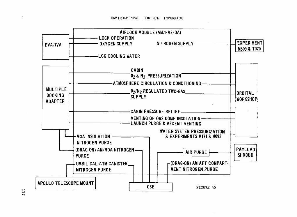
ENVIRONMENTAL CONTROL INTERFACE
AIRLOCK MODULE (AM/FAS/DA)LOCK OPERATION
EVA/IVA OXYGEN SUPPLY NITROGEN SUPPLY EXPERIMENTM509 & T020
LCG COOLING WATER
CABIN02 & N2 PRESSURIZATION
ATMOSPHERE CIRCULATION & CONDITIONINGMULTIPLE 02/N2 REGULATED TWO-GAS ORBITALDOCKING SUPPLYADAPTER WORKSHOP
CABIN PRESSURE RELIEFVENTING OF OWS DOME INSULATIONLAUNCH PURGE & ASCENT VENTING
WATER SYSTEM PRESSURIZATIONMDA INSULATION & EXPERIMENTS M171 & M092NITROGEN PURGE
(DRAG-ON) AM/MDA NITROGEN PAYLOADAIR PURGEPURGE SHROUD
UMBILICAL ATM CANISTER -(DRAG-ON) AM AFT COMPART-NITROGEN PURGE MENT NITROGEN PURGE
APOLLO TELESCOPE MOUNT

recorders, C&D panels, battery modules, EREP components, and electronic modules.
Two separate coolant loops are provided for redundancy. The passive portion of thesystem includes thermal coatings, insulation, and curtains acting as insulation. The suitcooling system provides astronaut cooling during EVA and IVA by circulating temperaturecontrolled water through suit umbilicals to the liquid cooled garments. Ground coolingand purge are provided by GSE cooling loops interfacing with in-flight heat exchangersand nitrogen purse gas introduced through a special fitting in the aft portion of the AMtunnel.
The test also included the related electrical communication and instrumentation com -ponents. The basic purpose of the test was to validate that the components had the en-durance to function properly for a complete mission. The test system was designed toload the components under expected flight conditions. Factory and CSC procedures arethe same.
The data were provided to the Panel on the development, qualification, and endurancetests at the component, module, and subsystem levels. These data indicated the systemcould meet the requirements. There are, however, a number of items remaining openfrom the test program and studies conducted by NASA and the contractor. The mostsignificant items are noted here:
1. Thermal capacitor. The primary AM hardware problem has been due to a re-quired redesign of the liquid cooling system thermal capacitor. The redesign was ne-cessitated by structural problems caused by phase change wax expansion. A new capaci-tor was designed and built. It is undergoing qualification test with an estimated comple-tion date of December 1, 1972.
2. Condensing heat exchanger separater plates. It appears that the separater plateassemblies started gas leakage long before they were expected. Redesign and retestwere initiated. The qualification test was completed. A 140-day life test is being con-ducted with expected completion on December 27, 1972.
3. EVA suit coolant loop pumps. During acceptance tests all four pumps failed tostart after 1 week dormancy in coolant loop fluid. Apparently interaction between loopmaterials and additives caused formation of nickel orthophosphate octalhydrate deposits(K 2 HPO4 with nickel from heat exchanger). These deposits prevented pump startup.NASA and contractor organizations are intensely investigating this problem. There ishope for a test start on December 15, 1972.
4. Condensate dump system. This was mentioned in the section of the report cover-ing the OWS. It is, though, an AM problem. The problem is indicated as failure todump condensate formed in the condensation heat exchangers into the OWS waste tank.This is due either to freezing in the exit port to one waste tank or entrapment of air inthe water line. Design changes are still in process and testing is scheduled for comple-tion around January 1973.
118

To better understand and predict ECS/TCS performance additional studies have been
instituted. These include (1) definition of the coolant loop performance, (2) recommenda-
tions on flight procedures when providing water cooling for the three crewmen during
EVA for various combinations of water loop operation, and (3) assessment of the impact
of the rescue mission on AM ECS/TCS. There appeared to be some discussion concern-
ing the GSE interface data needs and their control between KSC and MSFC. The extent
of this question and its resolution are not known. The question of how long the crew can
use the cluster if the ECS fails is one that must be answered in contingency planning.
Such contingency planning will be reviewed further in the next report.
The successful completion of all component-level qualifications testing coupled with
successful completion of the system level testing should provide the necessary confidence
in the AM environment and thermal control systems.
EVA/IVA subsystem crew hardware. - The Skylab EVA currently involves all three
crewmen for periods of up to 3 hours. During the first visit, 28-day occupancy, one EVA
is planned. The second and third visits require 3 and 2 EVA missions, respectively. It
is our understanding that there are no contingency EVA's planned at this time although
they are under consideration.
The EVA hardware includes such items as an exterior workstation, lighting, film
transfer mechanisms, handrails, oxygen, electrical power, and communications for
the three suited crewmen. The Panel did not examine EVA hardware in any detail other
than to assure that the cognizant organizations were delving into these systems to root
out the problems and resolve them. There appear to be no major problems, and those
items that were still open at the time of the formal DCR did not seem to be significant
(i. e., EVA foot restraint functional tests and requalification of the film transfer boom
device).
Electrical power system. - The EPS conditions power received from a solar array,
mounted on the OWS, charges the nickel-cadmium batteries and supplies load require-
ments. During orbital dark periods, power is supplied to the load from the nickel-
cadmium batteries. System output voltage is adjustable for proper load sharing periods
of parallel operation with other cluster power sources. AM power system normally
operates in parallel with the ATM power system to satisfy cluster power requirements.
The electrical power distribution system is comprised of positive isolated buses
with a common return. The negative bus is tied to the vehicle structure at only one
point (single point ground). The isolated buses may be tied together through two circuit
breakers by the crew when necessary. Overvoltage protection is supplied by bus shunt
regulators. The electrical power system protection is further discussed in the CLUSTER
FAULT CURRENT PROTECTION and SNEAK CIRCUIT ANALYSIS sections. The EPS is
shown in figure 46.
Because of prior spaceflight history and the fact that EPS is generally accepted as
the major, if not only, ignition source available on board the Skylab vehicles, the Panel
119

SKYLAB ELECTRICAL POWER DISTRIBUTION
OWSSOLAR AMARRAYS
LOADS
TRANSFER LOADS
ATM ATM ATSOLAR .ARRAYS
FIGURE 46

exerted additional effort in examining this system. The Panel specifically was interested
in the wiring harness design and installation, the system tests and their results, and
the FMEA and SFP analyses.
The wiring design, fabrication, and installation were watched very closely by not
only the contractor but NASA as well. It is pertinent to point out unique fabrication
techniques used as well as important details which point up the extra care taken. This
takes the form of a tabulation, but it will, no doubt, increase the readers confidence in
the EPS:
1. During fabrication the harnesses were "layed-in" rather than fed through the
module. This reduced installation time essentially eliminated wire damage due to
scuffing and cutting, avoided "captive" wire harness problems, and allowed access for
inspections.
2. Redundant wiring through separate routing paths was used to ensure that damage
which may occur to one line is not likely to occur to the other.
3. Where connectors were involved sufficient wire slack was left to effect easy
equipment removal. Connector clearances were made sufficient to preclude the need for
special removal tools. Adjacent connector interchangeability was avoided wherever
possible.
4. Insulation and buffering provided the following:
(a) A structural insulation barrier for unprotected power feeders
(b) 3600 fiberglass reinforced silicon or fluorel wedge-type cushion clamps
(c) Protected positive terminal strips with nylon dome nuts on terminal studs
and molded potting overall
(d) Protection of interior wiring not behind enclosed panels by polyimide,
aluminum, and NBG convolute covers
5. Special wire bundle restraint methods control wire runs and possibility of,
damage.
The AM went through an exhaustive series of tests: development tests, qualification
tests, spacecraft acceptance tests, supplier hardware acceptance tests, and special tests
to verify specific items of concern. Only the nickel cadmium battery life cycle qualifica-
tion test is incomplete. Its purpose is to requalify the redesign of the cells. The test
was initiated October 15, 1972.
Caution and warning system. - Various aspects of this system have been covered
under other sections of this report. The important point here is that the AM contains
the chief center or master unit for the cluster C&W system. This system is shown
schematically in figure 47.
During testing the rapid AP alarm was activated several times while the vehicle
was being illuminated with radiofrequency energy from the radiation simulator system.
This problem was resolved by replacing the existing wire bundle tied to the AP sensor
121

AM CAUTION AND WARNING SUBSYSTEM
AM OWSPARAMETER AM C&W PARAMETER
MDA/STS (4 EMERGENCY) INSTRUMENTATION(2 AUTSON)PARAMETER (33 CAUTION) PACKAGES (6 EMERGENCYCAUTION)INPUTS (6 EMERGENCY.
(2 EMERGENCY) (19 WARNING)
OWS TOCSM I h SLAVE DISPLAY AUDIO
PARAMETER 10 ID LIGHTS SYSTEM
2NAURNSN CAUTION HIGH LEVEL(2 WARNING) AM MPAND AUDIO AMP.CONTROL WARNINGWARNING
AND DISPLAY UNIT OWSMASTER ALARM
40 ID LIGHTS MASTER RESETATM 76 INHIBIT
PARAMETER SWITCHESINPUTS
(8 CAUTION) __
4 WARNING) AM OWSKLAXON KLAXON
FIGURE 47

with a new cable. It is double shielded with ferrite beads installed on each wire within
the cable.
The C&W system monitors fire and rate of pressure drop as well as bus voltages
throughout the cluster, critical temperatures, partial pressure of oxygen, cluster atti-
tude, etc. From the material reviewed by the Panel this system appears to be in good
shape. The controls exercised by management and technical personnel indicate that this
confidence is well placed. A further check of this system will occur during end-to-end
testing at KSC.
Crew equipment. - This system consists of control and displays, mobility aids,
lighting, stowage, communications and utility power outlets, and in-flight maintenance
equipment. Essentially all of the problems identified in the SOCAR, DCR, and SAR have
been closed or plan developed to achieve proper resolution. In the area of instrumenta-
tion and communications there are numerous qualification status .reports still awaiting
completion and approval by NASA. These should be accomplished as quickly as possible
to assure proper documentation is available where and when it is needed. The same
problem appears to exist with respect to a number of I&C intercenter ICS's. Another
item to be closed out at KSC in February 1973 is the AM data recorders since acceptance
testing was not complete at the time of AM turnover. A system performance summary
chart used at the DCR provides additional data on the AM data subsystem (table XV).
During altitude chamber testing the Mosite packing material used in stowage con-
tainers swelled and contracted due to entrapped gas in the interstices of the Mosite. This
material problem is applicable to both the AM and MDA. It is discussed more fully in the
CLUSTER MATERIALS section. The problem is being resolved by changing material
and reworking current locations to preclude interference between Mosite and hardware.
The in-flight maintenance program was reviewed in detail during the SOCAR activi-
ties. There were three significant results from the in-flight maintenance team report:
A. At the present time the IFM activity integrates all onboard tools to
ensure availability and to preclude duplication. However, there is no formal
method for cluster tool requirements, other than for in-flight maintenance
tasks, to be transmitted to personnel involved with IFM. Consequently, the
SOCAR Team Chairman recommends that action be taken to have the IFM
program expanded to include activation, deactivation and operational tasks
which involve tools, spares and/or servicing. He will also ensure that
extravehicular mobility unit (EMU) and microbial contamination control
tasks are adequately covered in the operational documentation.
B. Level II CCB approval of new IFM tasks requires too much time. A
crew IFM procedure, in addition to other task data, will be provided by
module contractors. MSC will review the procedure and other task data and
verify the task as necessary. This will reduce approval time, changes, and
revisions later on in the program.
123

C. Many inconsistencies exist in IFM program documentation. These dif-ferences are primarily between the IFM baseline document (LS-005-003-2H)
and the Operations Handbook.
The Panel, as a result of its review of data presented at the DCR's and SAR's, feelsthat these problems are well in hand and envisions few difficulties in the future.
Risk Assessment and the Management System
MDAC-East's management systems effectively used Mercury and Gemini exper-ience. They also made efficient use of NASA and intracompany support.
MDAC-East has used a series of tools to assist in the identification and solution oftechnical problems in a manner much the same as other contractors. These tools in-clude FMEA, design reviews, use of NASA alerts, continuous management review ofdesigns and procedures for hazard identification and resolution, personnel motivationprograms, test and development organizations, and tight vendor control. The result isour confidence in management and the flight systems.
MDAC-East used meetings of in-house and NASA personnel on a daily, weekly, andmonthly basis to discuss status, problems, solutions by engineering, manufacturing,test, and management.
Test procedure formulation and actual test activity appears to have been closely co-ordinated with and monitored by NASA. Where anomalous conditions were encounteredand corrected it again appears to have involved a high degree of coordination and infor-mation interchange with NASA. The test program is carried out at the factory and at thetest site as shown in the schematics (figs. 48 and 49).
MDAC also conducted a self-assessment in terms of the findings and recommenda-tions of the Centaur and Thor-Delta report. They noted the key personnel, including allengineers, have been given motivation and orientation lectures, and that NASA/MDACmotivation material is used to maintain continuous attention to this area. Vendors werefurnished the same material. Vendor hardware penetration surveys concentrated on howthe vendor personnel actually design, fabricate, test, and handle the hardware. As de-ficiencies were noted they were quickly examined and corrected to preclude further im-pact on the factory design, test, and fabrication. Internal AM reviews were structuredto take into account ease of assembly based on the need to inspect and test.
To further understand and reduce the hazards on the AM, MSFC directed MDAC-Eastto expand the on-going AM and AM/GSE FMEA program to include the following failuremodes: (1) relays and switches with respect to premature operation and failure to ceaseoperation, (2) circuit breakers with regard to short to ground on unprotected side, and(3) connectors with regard to open and shorted pins. This expanded program resulted in
124

AIRLOCK MODULE
ACCEPTANCE TESTING
VENDOR CONTRACTOR
PLANTS &MDAC-E ATLO* ATLO*
ACCEPT AM ACCEPT FAS
AM AM/FAS
COMPONENTS AM/MDA ELECTRICAL
SUBSYSTEM AAM SOFT MATE INTERFACE
ACCEPTANCE SYSTEM AM MATE & VERIFICATIONALTIUE ASSEMBLE IALIDATION WEIGHT EMS T A I & SHITEST INTAL O / S L PRETEST AM COMPONENTS AM/FAS NTERCE METEOROID
MDAC-E PTEST & C.G. VERIFICATION SHIELD FIT
SUBSYSTEMS
DEMATE AM ATLO*STRUCTURAL FROM MDA ACCEPT DA
& FASTAM MOD RETEST -AM/FAS/DA/MDA
STOWAGE & AM/MDA HARD MATE DEPLOYMENTSIMULATED & AM/MDA INTERFACE SYSTEMS AM/MDA CLEARANCEFLIGHT && C SYSTEMS ASSURANCE CHECKS &O.R.I. 2 2 VERIFICATION TEST ALIGNMENT
VERIFICATION
MANNE D EREP _ POS T T EST
UNMANNED ALTITUDE EREP SYSTEMS TEST ANALYSIS & SHIPALTITUDE CHAMBER TEST CHAMBER INSTALLATION 6 SIMULATED PREP. TO TO KSC
(84 HR TOXICOLOGICAL) TEST FLIGHT SHIP
*ACCEPTANCE TEST AND LAUNCH OPERATIONS DIVISION
FIGURE 48

AM/MDA/FAS/DA/PSACCEPTANCE TESTING
TEST SITE
AM/MDA OFF LOAD O&C O&C O&C P.I.B.& INTEGRATED INVERTED MATE ALIGNMENT MATE
RECEIVING -- SYSTEMS - DOCKING -- & GAS SYSTEMINSPECTION TEST WITH CSM DEPLOYMENT I PRESSURE
AM/MDA/DA/ TESTFAS
FAS OFF LOAD
RECEIVING P.S.INSPECTION CYLINDER
OFF LOAD MATEO DA - &
RECEIVING OWSINSPECTION
NOSEg CONE
VAB
SWSMOVE TO CLUSTERLC-39 SYSTEMS
TEST
FIGURE 49

the evaluation of approximately 29, 000 additional conditions of failure. Completion of
this effort is expected by February 1973.
Meetings have been held periodically with Martin Marietta Corporation integration
personnel and appropriate NASA personnel to resolve safety problems and noncompliance
items encountered during system safety checklist analyses. As an example, special
analyses were conducted to determine the flammability characteristics of flame propaga-
tion in the condensing heat exchanger and the molecular sieves modules.
The Panel asked about the high pressure gas system which carries nitrogen and
oxygen into the onboard systems. It appears that the high pressures from the storage
bottles surrounding the AM are carried to the basic AM structure (internal) before a
pressure reduction valve system comes into play to reduce pressures to those needed.
Prior experience has indicated that such pressure reductions should take place as close
to the high pressure source as possible. If this is the case, the rationale for this design
decision should be included in the SAR.
Inspection of the AM by the walk-through NASA group indicated that there were
several instances of electrical cables in close proximity to sharp corners and edges and
that some wiring was "squeezed" into containers and trays.
In summarizing the discussion of the AM systems the following open items are noted:
1. ATM deployment mechanism tests on jammed or "frozen" trunnion bearings
2. In the ECS/TCS -
(a) Thermal capacitor requalification test
(b) Condensing heat exchanger life tests
(c) EVA suit coolant loop pump corrosion problem
(d) Condensate dump system design change and retest in process
3. Nickel cadmium battery requalification test
4. Life test of the partial pressure oxygen transducer life test
The material presented to the Panel indicated an adequate AM management system.
Again it is of the greatest importance to maintain the same high level of motivation
and competence on the program as the AM moves through the test, checkout, and launch
preparations period at the KSC.
MULTIPLE DOCKING ADAPTER
The multiple docking adapter (MDA) is the control center for Apollo telescope mount
(ATM) and Earth resource experiment package (EREP) experiments. It is mounted on
the forward end of the airlock module, and provides a docking post for the CSM's and a
structural support to docked spacecraft. The MDA is a 10 1/2 foot diameter cylinder
and is slightly over 17 feet long (see fig. 50).
The primary port for docking the CSM is axial and located at the forward end. The
127

MDA
HARDWARE ELEMENTS - EXTERIOR
MICROMETEOROID SHIELD MDA VACUUM VENT
DOCKING TARGET SUPPORT MDA/AM ELECTRICAL FEEDTHRUCOVER ASSY
-Z
-Y+Y RADIATOR
SERVICE
+Z VALVES
AXIAL DOCKING PORT AFT RADIATOR
GROSS ORIENTATION LIGHTS(4)
PROTON SPECTROMETERINVERTER/LCA
EREP S194 EXP RL-BAND ANTENNA RADIAL
PORT CKING EREP S192 EXPEREP S191 EXP INFRARED SPECTROMETER EREP S190 MULTISPECTRAL SCANNER
EXP WINDOW -FORWARD RADIATOR
FIGURE 50

alternate port is located on the side of the module. Cameras and EREP sensors are
located adjacent to the alternate docking port. Some look through a window in the wall,
others actually protrude through the wall. Vaults are provided for storage of cameras
and film for the ATM experiments. These vaults protect the film from the radiation en-
vironment experienced at orbiting altitudes.
The control and display console for the ATM is located in the rear of the module. It
contains all the controls and instruments required for operation and observation of the
ATM solar astronomy experiments. This control and display console also contains the
instruments and controls for the ATM attitude control system and for the ATM electrical
power system.
The MDA presented unique management challenges. It was initially designed and
partially manufactured at Marshall. Then the utilization contractor in support of
Marshall assumed responsibility to complete and equip the module. Finally, it was
shipped to another contractor site for mating with his module and integrated testing.
Thus, transfers of work and joint operating agreements had to be well defined. This is
one illustration of the variety of contractual and operational situations in Skylab. That
these arrangements were managed as well as they were speaks well for the contractor
and NASA.
Management Aspects
The MMC-Denver did not have direct experience with management of manned space
vehicles. However, they had substantial background in both manned (Gemini) and un-
manned vehicles as well as manned spacecraft studies (Dynasoar, MOL). They have
achieved a high degree of proficiency in carrying out their roles and responsibilities. In
its review the Panel examined the pattern of problems encountered and the problem
solving mechanisms. We also reviewed mechanisms to assure (1) senior management
visibility of in-house operations, (2) assimilation and use of prior hazard knowledge and
overall risk assessment experience, (3) quality assurance, (4) vendor control, and
(5) intercontractor/NASA coordination. Activities to integrate the MDA into the cluster
were of particular interest because of the contractors' overall integration role and the
interfaces between the MDA and MSFC's Apollo telescope mount and the MSC Earth re-
sources experiment package.
Special attention had been given to personnel responsibility, attitudes, and skills.
MMC considers the PIE concept as one of the major contributors to goals of excellence
in design, test, manufacturing, and change control. The PIE is a highly qualified,
specialized engineer assigned by the program manager. He has the responsibility for a
specific area of emphasis on a continuous basis. Specific areas of emphasis include
129

subsystems, major components, test, materials and processes, etc. He has the re-
sponsibility for the technical integrity of all phases of design, development, fabrication,
test, and operations. In his work of preventing, recognizing, and solving problems he
provides upper levels of management with the required visibility for them to make ade-
quate and sound decisions. Specific procedures were issued to cover the PIE concept
and its implementation. From the material presented to the Panel it appears that this
system has worked well and provides both vertical and horizontal control of the MDA
program.
The training and certification program is much like that of other Skylab contractors
and appears to be thorough and consistently implemented.
The results of the Centaur/Delta boards were reviewed in depth by the managers
assigned to manufacturing, test, and quality. MMC made special efforts to contact
specific members of the Centaur board who could be helpful in providing MMC with
more detailed insight into the workmanship and management problems that might be
applicable to their own program. It was apparent that MM C initiated steps to achieve
improvements in their system wherever warranted. This willingness to accept the prob-
lems and solutions of others indicated an openness that most certainly would aid in
achieving successful hardware.
In its early reviews of MMC, the Panel noted that the normal problems inherent in
any large scale program were evidenced here, but that, like any of the other contractors,
they were aware of them and resolving them as quickly as possible. The fact that MMC
was the system integration contractor provided them with greater visibility of the pro-
gram and the on-going problems. This in turn permitted them to look into their own
operations with more knowledge. On the whole, the management systems and their
implementation at MMC appeared to be in good shape and provided further confidence
that not only their own hardware but the integrated cluster hardware would more nearly
meet its requirements.
The interfaces illustrate the depth of MMC's penetration into the program. These
interfaces involve EREP support equipment, medical and scientific experiments, asso-ciated GSE, Skylab experiment GFE and ICD configuration management, mockups and
training equipment, and engineering support.To assure that adequate skills continue to be available, key personnel are identified
by discipline and name for retention to provide failure/anomaly review and analysis,test site support, and mission support. Furthermore, MMC is involved in the logistic
support area- dealing -with spares and repair depot efforts. Skylab postdelivery support
covered the following four areas:
130

Medical and scientific experiments October 1971 through August 1972
at MDAC-West
EREP and scientific experiments at June 1971 through August 1972
MMC and MDAC-East
KS C experiment support August 1972 through December 1973
Denver engineering support Current through December 1973
Hardware Aspects
In the design of the MDA, as in the other Skylab modules, the use of prior manned
space programs experience and hardware played a very prominent part. For example,
the design specifications, materials data, cleanliness, and general safety criteria were
derived from Apollo and Gemini programs. In the case of hardware the following items
were used:
Fire extinguisher (Apollo) Docking drogue (Apollo)
Connectors (Apollo) Docking targets (Apollo)
Flex lines (Apollo) 4-port selector valves (Apollo)
Fans (Apollo) AP gages (Apollo)
Equalization valve (Gemini) Running lights (Gemini)
The experiments mounted in and on the MDA are covered in the EXPERIMENTS
section of this report. The ATM C&D panel is covered under the APOLLO TELESCOPE
MOUNT section of this report.
Throughout the design, fabrication, and testing of the MDA there has been crew
participation. This close coordination and consultation has been most helpful in producing
a vehicle to meet the hardware and crew requirements in an optimum manner.
Some of the program concerns noted in the January 1972 review by the Panel are
still present in the program. This is particularly true of the amount of deferred work
due to nonflight hardware used in place of flight equipment.
Structures
There have been no significant design changes to the basic structure since the
critical design review. Items of structural interest which are indicative of the ability to
meet and resolve problems include the L-band antenna truss, pressure hatches (axial
and radial), windows, window covers, and stowage containers.
The MDA proof pressure and leak test indicated that the actual leakage rates were
some 20 percent of the allowable (1. 097 lb/day versus 5. 280 lb/day). All of this occurs
131
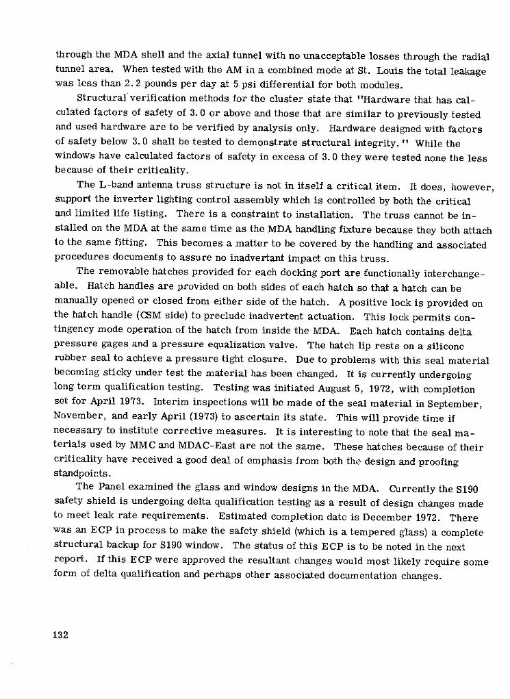
through the MDA shell and the axial tunnel with no unacceptable losses through the radialtunnel area. When tested with the AM in a combined mode at St. Louis the total leakagewas less than 2.2 pounds per day at 5 psi differential for both modules.
Structural verification methods for the cluster state that "Hardware that has cal-culated factors of safety of 3. O0 or above and those that are similar to previously testedand used hardware are to be verified by analysis only. Hardware designed with factorsof safety below 3. 0 shall be tested to demonstrate structural integrity. " While thewindows have calculated factors of safety in excess of 3. 0 they were tested none the lessbecause of their criticality.
The L-band antenna truss structure is not in itself a critical item. It does, however,support the inverter lighting control assembly which is controlled by both the criticaland limited life listing. There is a constraint to installation. The truss cannot be in-stalled on the MDA at the same time as the MDA handling fixture because they both attachto the same fitting. This becomes a matter to be covered by the handling and associatedprocedures documents to assure no inadvertant impact on this truss.
The removable hatches provided for each docking port are functionally interchange-able. Hatch handles are provided on both sides of each hatch so that a hatch can bemanually opened or closed from either side of the hatch. A positive lock is provided onthe hatch handle (CSM side) to preclude inadvertent actuation. This lock permits con-tingency mode operation of the hatch from inside the MDA. Each hatch contains deltapressure gages and a pressure equalization valve. The hatch lip rests on a siliconerubber seal to achieve a pressure tight closure. Due to problems with this seal materialbecoming sticky under test the material has been changed. It is currently undergoinglong term qualification testing. Testing was initiated August 5, 1972, with completionset for April 1973. Interim inspections will be made of the seal material in September,November, and early April (1973) to ascertain its state. This will provide time ifnecessary to institute corrective measures. It is interesting to note that the seal ma-terials used by MMC and MDAC-East are not the same. These hatches because of theircriticality have received a good deal of emphasis from both the design and proofingstandpoints.
The Panel examined the glass and window designs in the MDA. Currently the S190safety shield is undergoing delta qualification testing as a result of design changes madeto meet leak rate requirements. Estimated completion date is December 1972. Therewas an ECP in process to make the safety shield (which is a tempered glass) a completestructural backup for S190 window. The status of this ECP is to be noted in the nextreport. If this ECP were approved the resultant changes would most likely require someform of delta qualification and perhaps other associated documentation changes.
132

Environmental/Thermal Control Systems
The MDA uses the active ECS and TCS of the airlock module. The MDA contains
its own passive system along with heaters as required. The passive thermal system
consists of insulation blankets, paints, and coatings. The active system includes ducting
and fans to circulate the atmosphere, heaters and associated thermostats, and coolant
loops for the ATM C&D console and the EREP water loop and MDA radiator. The en-
vironmental control system consists of vent valves, equilization valves, mufflers,
ducting, diffusers, and the like. Problems in this area have in general involved the
ATM C&D and the EREP equipments. The basic MDA ECS/TCS hardware and test pro-
gram appeared to offer few problems. The SOCAR determined that some minor hard-
ware and documentation discrepancies existed. To our knowledge they have all been re-
solved. There were however some cases where flow tests were not conducted and the
test deviation accepted on an analytical base. Typical were the flow and pressure drop
test of ATM/EREP coolant system. The SOCAR indicated that the only discrepancies
were associated with the valves and AP gage. This indicated few concerns here.
Electrical Power System and Caution and Warning
The MDA electrical system interconnects all electrical hardware between CSM/AM/
ATM and other MDA loads. There are some 40, 000 feet of wire with approximately
8, 000 connections. As in the case of the other modules the wiring, when not conducted
external to the manned areas, is covered in sleeves and trays that eliminate to the
greatest extent possible proximity of flammables and ignition sources and propagation
paths. Figure 51 is a simplified schematic of the cluster EPS. Of interest here is the
relative dearth of equipment in the MDA in comparison to other modules. There appear-
ed to be few areas of concern in this EPS and all are indicated to be closed.
The fire detection system in the MDA is comprised of two ultraviolet fire sensors
(identical to those used throughout the cluster) and one fire sensor control panel. No
anomalies were apparent in this system during the various phases of the acceptance re-
view cycle. Any SOCAR actions have been closed. MMC's attention to the actions taken
by MDAC-East, MDAC-West in their C&W systems seems to have paid dividends in their
MDA efforts.
133

SIMPLIFIED DIAGRAM OF THEELECTRICAL POWER SYSTEM
NOTES:
ATM . EACH PWR RELAY SHALL BE INDEPENDENTLY CONTROLLED BY:iTM L A. MANUAL SWITCHES 8. OCS COWANDS
COa PWR RELAYS 'IALL UL UPLNLD BY TIll AM PWR DI.(11ONNECT SWITCHESD LOADS 18 CBRM SOLAR THE SPG LONTACTOR SHALL IL INULPLNULNILY 0ClliOLLDLO 7BYARRA A. MANIIA1 SWITCHES 8. oCS COYINDS
PUS Itt!S 0 PWR NLAYS ',IALL DL OPLNED BY TEIL ATM [MLl PkR Orf SwITCN, 0I11021 7D11 CSM OULKLO TO AXIAL PRUNT ONLY
cuo" 70 OM ANY PCG CAN G CON;ECTED TO EITHER REG. BUSSCI AM RAlI cR RE CONNFCTED TO O
LEITHER BEG BUS
AARRA
"O EER-4 PCG Po- - O
Ail. T ?A
L I AM RETURN ONTROLE S 8 0s LOADS
_US_ __ __ COMMON1--BUS TI
AM BUS 1
TURN
I-RETURN
RETURN
POOERW
PNPT LUNIOE
RELAI c PCG5 A U
1 PARELY RELTUR BU
- 5
TRANE- RELAYBUS A M cCOMO
L"D RETURN
AM AMBUS? LI 8052RETURN U
FIR 51

Instrumentation and Communications
The instrumentation system includes 89 measurements for temperature, hardware
and experiments, and internal pressure. The communication system includes speaker
intercoms, headsets, voice down-link via the CSM, and television input station and ad-
junct equipments. The MDA provides for all cluster television input stations. It includes
a television video switch which permits selection capability in the television system and
couples the video signal to the FM S-band transmitter in the CSM. In addition, it signals
conditions and amplifies the ATM signals. Because of these multiple interfaces the
interface control documentation system is most important. There were a number of
open PIRN's to the basic ICD's. These should be closed as quickly as possible to pre-
clude problems at the KSC during test and checkout operations. The history of the tele-
vision systems, both on the Skylab program and prior manned/unmanned programs, in-
dicates that this area requires a special effort on the part of management to assure that
all will be in readiness by launch time.
Crew Equipment System
There are stowage areas using the Mosite material which has been discussed else-
where. Repair materials and in-flight maintenance tools are also found in the MDA. One
problem that still exists is the inverter/lighting control assembly. It generates noise at
a level which appears to disturb the crew. The status of this problem will be noted in
the next report. Test activites at KSC appear routine except for the evaluation of new
mods to the axial hatch. This requires a crew test with MDA in the horizontal position.
Ground Support Equipment
The GSE, including that supplied by NASA, has been used during the process of
testing the MDA at both Denver and St. Louis. There are a few significant items of note
which should probably be resolved prior to extensive testing at KSC. These involve the
Skylab television test set, an electronic test set (GFP), and data quick look system and
fit checks. There have been no indications that the GSE has over-exercised the flight
hardware during the testing to date.
Management and Risk Assessment
While there were no doubt "growing pains" and learning experiences the quality of
.the MDA basic hardware reflects well on the individual skill, dedication, and thorough-
ness of management. A characteristic of the MMC efforts is the early and strong partici-
135

C-
MDA
FLIGHT ARTICLE FLOW DIAGRAM
KSC CHECKOUT OPERATIONS
00 KSC KSC KSC KSC KSC KSC
S'AM/MDA CSM/AM/MDA AM/MDAELECT RIC ,A D.A./EXPERIMENT MOVE To FAS/AM/MDA.I.INTEGRATED ELECTRICAL, M ATMp SINTEG ATE ST D A.HARNESS TO LV/OWS ATt IDOC KIN G & SYSTEM TESTS MATE
SYSTEM TEST LEAK TESTS VERIFICATION MATE
MSFCVENDOR KSC
ATM LA( NCHCSM DEPLOYMENT VEHICLECHECKOUT ASSEMBLY ORBITAL
CHECKOUT WORKSHOP
KSC KSC KSC KSC KSC
AM/MDA/OWS/ATM SWSAM/MDA/OWS/ATM AM/MDA/OWS AM/MDA/OWS TO LV/OWS OPERATIONS
SELECTRICAL INTER- LAM/MDA/OWS END TO END SYSTEM -+ELECTRICAL IISWING ARMFACE TEST & EXPERIMENT TESTS MATE & OVERALLTEST
INTERFACE TEST (SA OAT)
KSC KSC
sws MOVE TO SPACElo SIMULATED VEHICLE
FLIGHT TEST LAUNCH PAD CHECKOUT FIGURE 52

pation of the flight operations people in the hardware development program, again due in
part to the integration working groups.
The MDA is expected to progress through its KSC cycle in the manner shown in
figure 52. The open items noted in the preceeding discussion indicate no particular
problems of significance should be expected during the KSC period. The experiments
contained within the MDA are not a part of this discussion but are handled separately in
the EXPERIMENTS section of this report.
PAYLOAD SHROUD
The payload shroud (PS) is designed to provide an environmental shield during the
final stage of assembly/checkout and launch. It is also an aerodynamic fairing for launch
and boost phases. Finally, it provides structural support to the Apollo telescope mount
during prelaunch, launch, and boost phases.
The PS separates on command into four discrete segments. Radial velocities are
sufficient to prevent recontact with the payload. Separation is effected through segment
joints containing an explosive/bellows linear thrusting device located along the longitudinal
segment separation lines. The shroud is unlatched prior to separation by explosive oper-
ated latch actuators. These are located at the segment joints for structural continuity.
Separation is further aided by the use of tension cleats and bolts which fasten the lower
end of the PS to the fixed airlock shroud.
This unit is handled in somewhat different fashion than other modules contracted to
the MDAC-West and East divisions. The airlock payload shroud is contracted to MDAC-
East as part of the airlock program. However, the shroud was manufactured by the
MDAC-West special space programs office. This arrangement has not hampered the de-
velopment and interface efforts in any way.
The general configuration of the PS is a double angle nose cone mounted on a 260-
inch diameter cylindrical section 350 inches long. The forward nose cone has a 250 cone
angle and is 182 inches long. The aft cone is 142 inches long with a 12. 50 cone angle.
The total length of the shroud is 674 inches long and it weighs approximately 25, 000
pounds.
ATM launch loads are reacted by the PS support structure located at 900 intervals
on the forward end of the cylindrical section. Provisions are made in the PS for access
doors. The Saturn V damping system will be attached for use during transit from the
VAB to the launch pad and for servicing while on the pad.
The PS acceptance review was conducted on August 10, 1972, and the Material
Inspection and Receiving Report (Form DD250) was signed on August 31, 1972. It was
received at KSC on September 22, 1972, well in advance of the KSC need date.
137

The jettison system for shroud separation in orbit was verified through componentand full scale testing at the Plum Brook Facility, Cleveland, Ohio, vibro-acoustic test-ing at MSC, as well as other needed tests for qualification.
At this time one item remains to be qualified in the separation and ordnance sub-system. The diode modules are inaccessible for removal before flight. While they arenow a nonfunctional flight item, assurance is required that they will not contaminate thepayload.
The only open problem is the resolution of the shrinkage in the linear explosiveassembly as a result of environmental conditions during storage prior to shipment toKSC. It is assumed that the new thermal conditioning process and environmental controlof the shipping and storage modes should take care of the shrinkage problem.
APOLLO TELESCOPE MOUNT
The ATM houses a sophisticated solar observatory. It also provides attitude con-trol to the cluster, and, by means of its solar arrays, provides about half the electricalpower used by the cluster. The ATM consists of two concentric elements. The outerelement, the rack, is an octagonal structure 11 feet from side to side and 12 feet high.The inner structure is the solar experiment canister and is about 7 feet in diameter and10 feet long. Figure 53 shows the ATM and its component parts in relation to the totalSkylab cluster.
The rack, in addition to supporting the canister, supports the four ATM solar arraysand contains the components of the attitude control system, the ATM communicationssystem, and the thermal control system that maintains the temperature of ATM equip-ment within required limits. The canister is mounted in the rack on gimbals which allo vit to rock 20 about two mutually perpendicular axes. A roll ring allows the canister torotate about its axis. These features make it possible to point the experiments at theirtargets with greater precision than can be accomplished with the cluster alone.
During launch and ascent to orbit, the ATM rack is directly supported by the PS.When the shroud is jettisoned, the support structure assumes the structural support task.The ATM support structure, which connects the rack to the forward end of the fixed air-lock shroud on the AM, incorporates a deployment mechanism that rotates the ATM 900from its launch position in front of the MDA to its operating position alongside the MDA.Two work stations are provided so that an astronaut can perform the EVA task of changingthe cameras and film magazines for the solar telescope.
The ATM is the major in-house development task that is performed at MSFC.MSFC has the total responsibility for the design and development including the experi-ments produced by a number of different PI's and their contractors. From the point ofview of the total mission, the ATM experiments are supported by a ground-based ob-
138

ATM
FIGURE 53
ORIGINAL PAGE ISo POOR QUALITy
139

servatory astronomy program. As in any major hardware program the ATM program
included a one-G trainer, thermal vibration unit, ATM prototype unit, and the necessary
adjuncts.
The discussion of the ATM will include the associated experiments only as they
impact the basic ATM as a module. The experiments themselves are covered in the
EXPERIMENTS section of this report.
Management Aspects
A project office was set up under the Skylab Program Manager at MSFC. It used the
various MSFC organizations such as engineering, astrionics, astronautics, manufactur-
ing, and other groups. Subcontractors and vendors supplied many of the components.
Because it was in-house the coordination and information flow between MSC and other
affected NASA Centers was quickly and adequately set up. The geographical distribution
of major elements of the ATM program are shown in figure 54. The management sys-
tems used an integrated team effort, configuration management and interface engineer-
ing, review process as well as a dedicated team of specialists to follow the ATM through
testing program and the KSC test and checkout program right through launch prepara.-
tions. While this was an MSFC in-house effort the same formal documentation was re-
quired as for the other modules.
The manpower varied from a high of over 2000 NASA/contractor personnel to a
current number of something over 1000. The ATM program activities are shown infigure 55.
The ATM was subject to the problems inherent in a program starting in one di-
rection in the early days of the Apollo application program and then being reoriented asthe Skylab program was becoming more clearly defined. On the whole the ATM manage-
ment systems and their implementation appear to be good and working well. An areathat will have to be emphasized throughout the launch preparations at KSC is the cleanli-ness requirements in and around the ATM module.
Hardware Aspects
In -its review of- the ATM the Panel concentrated on the electrical power system, theattitude control system, EVA, and thermal control system. Other systems such asstructures, mechanical, instrumentation, and communications were covered to a lesserextent. As in all its reviews the transferred work to KSC was a special area of interest.At the ATM preboard turnover the number of actual manhours of work to be transferredto KSC was 26 hours.
140

GEOGRAPHICAL DISTRIBIfION OF MAJOR ATM EFFORT
AMERICAN SCIENCE& ENGR
HIGH ALTITUDE BALL BROTHERS HARVARD COLLEGE S-054 EXPERIMENTOBSERVATORY
OESERVATORY INSTRUMENT BUILDER BOSTON
S-052 EXPERIMENT FOR HAO, HCO, NRL S-055 EXPERIMENT
BOULDER BOULDER BOSTONPERKIN-ELMER
EXPERIMENT POINTINGNORWALK, CONN.
BENDIXNOAA
CONTROL MOMENTGROUND NETWORK GYROS
BOU LDER TETERBORO, N. J.
MARTIN MARIETTA NAVAL RESEARCH LAB
CONTROLS & DISPLAYS _ S-082 EXPERIMENT& CLUSTER
INTEGRATION WDENVER
IBM
DIGITAL COMPUTER
SYS. & OPERATINGSOFTWARE
HUNTSVILLE
LOCKHEED WHITE SANDS MANNED SPACECRAFT KENNEDY SPACE
TEST FACILITY CENTER CENTER SFC
OPTICAL TESTING LAUNCH MGT, DESIGN,
RYE CANYON EXPERIMENT OPERATIONS ASSY, TESTING,DEVELOPMENT & TESTING, TRAINING, TRAINING
CALIBRATION MISSION OPS, VIBRO- HUNTSVILLEWHITE SANDS ACOUSTIC TESTING
HOUSTON
FIGURE 54

ATM CONFIGURATION DEFINITION & ASSOCIATED ACTIVITIES
Preliminary Preliminary Critical MSFC/KSC Design FlightRequirements Design Design Acceptance Cert. ReaumnessReview Review Review Review ,Rev. Review
S(Hq) (Hq)I I
Preliminary FIt Module Fit ModulePreliminary Detail Design Manufacturing & Checkout Integrated Checkout
Checkout
LaunchDel to KSC
MSFC ATM Team Support
Formal Configuration Control
0 9 FIGURE 55

Open items at the time of the DCR included the following (closure will be noted in
the next report:
1. Attitude pointing control system (APCS). Control moment gyro shutdown was
due to high temperature of spin bearing during flight unit postthermal vacuum AST.
Additional rate gyro processor failures were encountered during flight unit postmanu-
facturing checkout. Failure analysis is now in work. Test at KSC in December 1972
should close this out.
2. Electrical power system. ATM C&D logic distributor delta qualification was due
to redesigned component. . Expected qualification completion is in November 1972.
Other known open items are of minor impact. In examining the material issued by
the Mathews team in late 1970 there were a number of items dealing with the ATM that
required clarification. These included the procedures used by MSFC to check the de-
signs, rationale for differences between the OWS and ATM solar arrays, and clarifica-
tion of specific design decisions, thermal control aspects, and the reliability of the
pointing system. These areas were all resolved to the satisfaction of the Mathews
team.
The ATM control and display panel received a good deal of attention not only from
the Panel but from the Skylab astronauts during C2 F 2 and hardware review activities.
The Panel's purpose here is to use the discussion of the ATM C&D panel as indicative of
the extent of coordination and effort expended by both NASA Centers (MSFC, MSC) in-
volved in Skylab in identifying problems and resolving them. It is applicable to the
entire spectrum of similar problems encountered during the development period of the
Skylab and, the Panel hopes, will be the manner in which problems will continue to be
resolved.
I During the MSC briefing to the
Panel on May 9, 1972, an assessment by the flight crew included some concerns in this
subject area as noted in a memo to the Skylab Program Director:
As a result of recent test participation, the Skylab flight crews had
identified a substantial number of idiosyncrasies of the ATM C&D which
required special crew procedures, or work arounds, to compensate for
the actual hardware characteristics. It was pointed out that the planned
ATM flight operations are already sufficiently complex that the burden
of these additional workarounds would substantially reduce crew effi-
ciency. The net effect was indicated as a very undesirable decrease in
the return of ATM scientific data. Since the corrective action for these
hardware idiosyncrasies was still in the consideration stage, Captain
Conrad recommended strongly in favor of correcting the hardware rather
than burdening the crew with the workarounds.
In recognition of the adverse effect of these numerous hardware
peculiarities, the ATM project personnel at MSFC have worked diligently
143

to correct the hardware whenever such action could be accomplished
within the major program constraints. Concurrently our flight crew
personnel have been directly involved in the day-by-day delibrations to
achieve the most economical solutions to the hardware issues. The net
result of this mutual effort is summarized in MSFC letter PM-SE/ATM-
784-72 of June 12, 1972, which lists 34 ATM hardware idiosyncrasies
and the corrective action planned. Of this total, MSC agreed with the
resolution of 31, accepted the disposition of two without further comment,
and recommended one for forwarding to the Level I CCB for resolu-
tion. . . . Subsequently, MSFC ATM engineering personnel worked out a
relatively simple hardware modification with no schedule impact, and
this modification has been approved for incorporation in the flight ATM
C&D during the present thermal vacuum testing activities at Houston.
Accordingly, this Center and the assigned Skylab flight crew personnel
are now satisfied that the proper corrective hardware action has been
taken to avoid any significant additional burden on the crew in operating
The ATM.
EXPERIMENTS
Management of the Skylab experiments is complex because of (1) the variety of the
experiments, (2) the design/fabrication requirements generated by data requirements,
(3) the late definition of some experiments, (4) the requirements for integration and inter-
face management, (5) the number of organizations involved, and (6) the data storage and
retrieval requirements. The Panel sought to understand the evolving management sys
tem in response to these factors. Particular attention was given to the maturity of the
system for risk assessments. Thus, the panel reviewed experiment design and fabrica-
tion, NASA/contractor responsibilities, NASA policies affecting experiment development
and utilization, experiment integration and compatibility with module hardware, safety
assessments, current posture of the experiment program, and projected operations at
KSC.
The Skylab Program Office has overall authority. Both MSFC and MSC have re-
sponsibility for the development of individual experiments. MSFC has the integration
responsibility. This ultimately involves a complex of people and organizations including
experimenters, contractors for the experiments, and module contractors where inter-
faces are involved.
As a point of background information, the policy for scientific investigation is noted
here:
144

The following statements constitute the Skylab policy for scientific in-
vestigations which is applicable to all Skylab principal investigators. It is
a general NASA policy that the principal investigator is to insure the timely
processing, analyses and publication of experiment results and findings.
Applicable requirements and constraints on the principal investigators for
the Skylab program are as follows:
1. Principal investigators will be funded by the Skylab program for a
maximum of 1 year from the time they receive the last of their flight data
from the NASA Experiment Development and Operations Centers in the
format as previously agreed to.
2. The principal investigators proprietary rights to the original scientific
data will normally expire at the end of the 1-year period when such rights are
granted in the original agreements by the experiment sponsoring program
offices. NASA does not plan to grant proprietary data rights to the EREP
principal investigators.
3. All original experiment data and reduced data will be available at all
times for review and study by NASA by arrangement in which the principal
investigators proprietary rights are fully protected.
However, NASA reserves the right to disseminate the results of any
experiment or group of experiments if it can be shown that this is in the best
interest of the Government. Such action would be taken only by joint direction
of the Office of Manned Space Flight and the Associate Administrator of the
experiment sponsoring program office.
This policy obviously effects the method of NASA/PI operations during the mission
and in some cases has influence the basic working agreements with regard to the experi-
ment hardware itself.
The management systems applied to the experiments area follow the pattern set for
the modules and in the case of MS C it varies little from that used on the Apollo program
scientific experiments effort. Management systems and controls consist of the following:
Program baseline/authority
Program plan
Resources management plan
Configuration management plan
Management guides
Status reporting and controls to assure measurement of progress against plans
(performance, cost, schedule)
Program reviews (internal, NASA Centers, NASA/contractor)
Problem control and resolution
Intercenter and internal panels
145

Safety assessments
Hazard identification
Risk assessment
Verification program
Development tests
Qualification tests
Integrated tests
Reliability and quality program
The development and integration sequence used for the experiments is shown in a
simplified form in figure 56. The DCR's have been completed and the experiments are
essentially in checkout at KSC. Some have had to be returned to the contractor for mod-
ification. The SOCAR and the DCR efforts were obviously most valuable in determining
hardware readiness and problems in both hardware and the operational documentation.
An example of the areas covered during the SOCAR are shown in table XVI. The Panel
has, in its reviews, received every indication that the technical management systems
can resolve the existing problems. The material that follows discusses some of the
hardware, problems, and status as known at this time. The purpose here is to indicate
the problem solving mechanism and its ability to provide confidence in experiment risk
assessment with regard to both the crew and the mission.
Crew Operations
Crew time for experiments is a prime resource in the Skylab experimental program.Use of available crew time and skill must be optimized by effective and realistic schedul-
ing of crew activities. The problem of available crew time versus experiment require-
ments appears to be one that is still to be resolved during the evolution of the missioncontrol documents. It has been noted that as a result of such tests as SMEAT the timerequired to accomplish certain of the experiments may be well beyond what was originallyanticipated. This requires an evaluation of the policy on scheduling the crew time line.It is evident from a consideration of the variety of experiments that each crewman mustbe versed in several skills but that it appears best to have only one crewman selected asan expert in a given major discipline. With different experiment emphasis for each seg-ment of the mission, the type of training and delegation of responsiblities will vary fromcrew to crew. Further information obtained from the Panel reviews indicates the follow-ing:
1. Because of the crews role in the biomedical program, they must have a thoroughunderstanding of the medical experiments. A qualified observer must act as the experi-ment conductor when the "medical" astronaut is used as the test subject. This requiresextensive cross-training in the medical area.
146

EXPERIMENT DEVELOPMENT & INTEGRATION SEQUENCE
Preliminary Preliminary Experiment Critical Configura- CeRequirements Design Definition Design Fabrication tion tReview Review Review - - Inspection - Fli(PRR) (PDR) (CDR) (C) Worthiness
(COFW)
Experiment Preliminary Integration InterfaceRequirements I nterface Compatibility Control Acceptance IntegrationDocument - Control -- Review Document(ERD) Document (ICR) (ICD)
(ICD)
O Design FlightCertifi- Readiness
8 SOCAR - cation - ReviewReview (FRR)
FIGURE 56 (DCR)

2. All three crewman must be trained to operate the ATM due to the extended
periods of time planned.
3. It appears that EREP experiments require two men to operate the equipment,
and attitude control operations probably require the efforts of all three crewmen.
Experiments
The experiment program consists of more than 50 items representing virtually every
field that has been recognized as being able to benefit from operations in near-Earth
orbit. The instruments, sensors, and other equipment for these experiments are locatedin various parts of the cluster, inside and outside. In addition to the permanently
mounted items, there are two airlocks in the OWS through which scientific instruments
can be operated outside the vehicle.
Medical Experiments
These experiments, including the specialized support equipment are the following(* indicates experiments integrated into the module hardware):
M071 Mineral balance
M073 Bioassay of body fluids
*M074 Specimen mass measurement
M078 Bone mineral measurement
*M092 Lower body negative pressure
*M093 Vectorcardiogram
Mill Cytogenetic studies of blood
M112 Man's immunity, in-vitro aspects
M113 Blood volume and red cell life
M114 Red blood cell metabolism
IMSS In-flight medical support system
M115 Special hematologic effect
*M131 Human vestibular function
*M133 Sleep monitoring
M151- Time and motion study
*M171 Metabolic activity
*M172 Body mass measurement
*S015 Effects of zero-G, human cells
*S071 Circadian rhythm, pocket mice
148

*S072 Circadian rhythm, gnat
*ESS Experiment support system
*IBCS In-flight blood collection system
The ESS provides a central source from which medical experiments are supported
with regulated electrical power, control and display panel, calibration, etc. This unit
is mounted in the OWS in close proximity to the experiments it serves.
The remaining vehicle tests that impact the medical experiments are the end-to-end
system tests, the experiment test at KSC, and the mission simulation/flight readiness
test at KSC. The results of the SMEAT have been described, as known by the Panel at
this time in the SMEAT section of this report. (M131 and M172 were not included in the
SMEAT test.) Qualification tests remain to be completed on the M133 and ESS.
Experiment M071, mineral balance, is impacted by the increased requirements for
urine collection noted in the SMEAT discussion. A procedure is required to use the new
4000-milliliter urine void in the mineral balance test. The complexity of the overall ex-
periment operation and its impact on crew timeliness is a concern. The appropriate
organizations at MSC and MSFC have indicated that this problem is being worked and
will be covered in the operational documentation. This also applies to M073.
Experiment M092, lower body negative pressure device, has received special em-
phasis because of the implications for crew safety. Factors to consider include flamma-
bility, crew egress, vacuum environment, and physical crew restraint while in use. In ad-
dition, it is considered one of the most important of the medical experiments. This ex-
periment is actually divided into three pieces of individual hardware: the lower body
negative pressure device, blood pressure measuring system, and limb volume measuring
system. The LBNPD prime contractor is the Marshall Space Flight Center. The prime
contractor for the BPMS and LVMS is the Martin Marietta Corporation, Denver. The
responsibility for the overall medical experiment M092 belongs to MSC. This experi-
ment is indicative of those experiments involving a number of different organizations,
geographically diverse, where extensive cooperation is required. Tests, FMEA, con-
figuration control reviews, and EMI reviews have indicated problems during the de-
velopment and testing of this hardware. These problems appear to have been resolved
to each program element's satisfaction. The system performed well during SMEAT.
Various body seals were tested. Operating limits were better defined.
The metabolic analyzer, M171, determines the metabolic rate in terms of oxygen
consumption and carbon dioxide production. It is used during periods of rest and cali-
brated exercise. Components include an ergometer, metabolic analyzer, body temper-
ature measuring system, and breathing apparatus. This is probably the most complex
hardware of all the medical experiments. Testing of these units during AST on the OWS
and the SMEAT uncovered a number of problems. These have been resolved or are in
process of resolution with no other forseeable problems. It is interesting to note that
149

the ability of the SMEAT crew to exceed expected energy inputs did cause failure of the
bicycle ergometer. The operational acceptability of the oxygen consumption analysis at5 psia appears to be somewhat of a problem. The resolution of this shall be noted in thenext report.
The prime contractors for experiment M131 are the Naval Aerospace Medical Re-search Institute and the Applied Physics Laboratory of Johns Hopkins University. Thisis basically a chair device used to rotate the subject at several optional angular velocitiesand it will be used to determine the effects of prolonged weightlessness on man's sus-ceptibility to motion sickness and on his judgment of spatial coordinates. Inherent inthis type of device are many potential hazards. The safety activities have identified 28of them: mechanical, -8; electrical, -7; pneumatic, -4; and operational, -9. Each hasbeen investigated, understood, and considered acceptable. Apparently the chair velocitywas erratic after 3 months of storage and the assessment of this appeared to be open atthe time of the Panel's review. The resolution of this shall be noted in the next report.
The in-flight blood collection system had not been finalized at the time of the lastPanel review. Only the prototype and development units have completed testing. Flighttype hardware was not expected to be available for testing until October 1972. Prototypehardware was tested in the SMEAT.
Those experiments requiring no in-flight hardware, such as M111, 112, 113, 114,115, and others, do not have direct hardware impacts. However, they do affect theoperations area. The Panel has no specific comments on these at this time. The M487,habitability/crew quarters hardware, is used for these experiments. The posture ofdocumentation and acceptability of the small hardware elements of M487 are not knownby the Panel at this time. The closure of this shall be noted in the next Panel report.
The following documentation needs to be updated. The closure of these items will.be statused in the next report:
1. The Skylab biomedical failure mode and effects analysis (FMEA) documentationfor the hardware components
2. The mission level FMEA documentation
3. The operational data book
Apollo Telescope Mount (ATM) Experiments
These experiments provide data on solar activities beyond that available fromEarth-based observatories. Experiments included in this group are the following:
S052 White light coronagraph
S054 X-ray spectrographic telescope
S055 Ultraviolet scanning polychromator spectroheliometer
150

S056 Dual X-ray telescopes
S082 XUV spectrograph/spectroheliograph H-alpha telescope
The ATM as an in-house program at MSFC used the management systems described
for the basic program modules. The experiment interfaces shown in figure 57 also in-
dicate the management controls necessary to execute this program. Contamination con-
trol is vital to these experiments both on the ground and while in Earth orbit. Contami-
nation would cause scattering and absorption in orbit and degradation of critical sur-
faces.
The crew interface with the ATM is extensive involving them in the operation of the
experiments from inside the vehicle and the EVA required to retrieve film. The time
spent by a crewman in the MDA at the ATM C&D Panel can run as high as 10 hours in a
24-hour period. The amount of time assigned to the ATM experiments in the crew time-
liness can be a problem if requirements are in excess of the available time to carry
them out. The problem is being assured by both the MSC/MSFC and Headquarters per-
sonnel. The following items will have to be monitored closely in the months ahead:
1. Film and camera stowage including associated C2F 2 activities
2. Damage to AM while traversing to MDA for film loading activities
3. Resolution of problems with image clarity on the S055A
In the fabrication of these experiments a number of new and/or unique techniques
were employed. These involved lubrication methods and materials, electrical discharge
machining, grating fabrication, development of heat rejection windows, and film strip
camera development. In all of these areas the development testing and acceptance
testing indicated that the workmanship and management controls produced the desired
product.
Earth Resources Experiment Package (EREP)
The EREP system includes equipment used for observing and analyzing Earth
phenomena from space. These phenomena include agriculture, forestry, geology,geography, air and water pollution, and land use. The equipment includes the following:
S190A Six camera multispectral photographic facility
S190B Long focal-length Earth terrain camera adapted from Apollo
S191 Infrared spectrometer boresighted with a viewfinder and tracking system
S192 13-Channel multispectral scanner (this spectral range overlaps the S190 and
S191 camera capabilities)
S193 Microwave radiometer/scatterometer and altimeter (K-band)
S194 L-Band microwave radiometer
151

ATM EXPERIMENT INTERFACES
MSF OSS
. IKSC MSFC SKYLAB MSC GSFC
LAUNCH FACILITIES PROGRAM SPACECRAFT CALIBRATIONLAUNCH OPERATIONS ASTRONAUTS
MISSION OPERATIONS
ATM PROJECT THERMAL VACUUM TEST
EXPERIMENTS
Ha TELESCOPES
NOAA PERKIN-ELMER,
HIGH NAVAL HARVARD
AS&E ALTITUDE RESEARCH LAB COLLEGE MSFCOBSERVATORY OBSERVATORY
BALL BROTHERSRESEARCH CORP.
FIGURE 57

Some 106 PI's have been selected for experiments using the EREP system. These
include 23 scientists from other nations. The equipment for these experiments is lo-
cated in the MDA with S193 located in the AM and the S190B in the OWS. Development
NEREP instruments began relatively late in the program. This resulted in the late
selection of PI's and later evolution of the management systems necessary to conduct
this segment of the program. These aspects of the EREP program had a salubrious
effect. Greater emphasis was placed on EREP than might otherwise have been the case.
On the other hand, the impact of EREP hardware problems late in the program tended
to cause adverse impacts on the testing and development aspects. It also presented
difficulties in maintaining a balance between operational compatibility evaluation and
analysis and the activity directed toward obtaining a basic knowledge of the flight sys-
tems and the flight objectives.
The EREP support equipment include the control and display panel, tape recorder,
viewfinder tracking system, S190 supplemental hardware, coolant system, structural
support, etc. Indicative of the complexity and sophistication of the EREP hardware are
the stowage requirements:
SL-1 Launch of the OWS, AM, MDA 188 items stowed
SL-2 Launch of the CSM 60 items stowed
Return with CSM 157 items stowed
Each successive CSM Launch 60 items stowed
The EREP management structure to meet the requirements of this program is shown
in figure 58. The major organizations involved in the hardware development are shown
in figures 59 and 60. This arrangement indicates the attention given the EREP system
by MSC.
Among the items still open are the following:
1. Descrepancies on S192, S193, and S194 require rework at the vendors.
2. ESE and functional interface verification for S192 and 193 will have to be com-
pleted at KSC.
3. Flight filters and desiccants for S190B have to be delivered; qualification testing
has to be completed.
The closure of these items will be noted in the next report. The earlier major concern
about the tape recorder and Malabee cooler appears to be resolved.
Based on the material presented to the Panel, we believe the actions being taken are
appropriate. However, this is an area that will continue to require careful attention
from contractors, PI's, and the NASA organizations involved. This requires continued
control of ECP's, waivers, and IRN's as well.
153

EREP MANAGEMENT STRUCTURE
OVERALL EREP MANAGEMENT AND INTEGRATIONSKYLAB MMC SUPPORT SYSTEMSPROGRAMOFFICE INTERFACE WITH SKYLAB SPACECRAFT
INTERFACE WITH MSFC
SCIENCE AND ENGINEERING AND FLIGHT FLIGHTAPPLICATIONS DEVELOPMENT OPERATIONS CREW OPERATIONSDIRECTORATE DIRECTORATE DIRECTORATE DIRECTORATE
SCIENCE REQUIREMENTS TECHNICAL SUPPORT FOR OPERATIONS PLANNING CREW REQUIREMENTSSENSOR DEVELOPMENT EREP ELEMENTS AND REQUIREMENTS SIMULATION AND TRAININGDATA UTILIZATION DISCIPLINE ORIENTED FLIGHT CONTROL OPERATIONS
ANALYSES DATA PROCESSING ANDSYSTEM ENGINEERING REDUCTION
FIGURE 58

EARTH RESOURCES EXPERIMENT PACKAGE (EREP)MANAGEMENT RELATIONSHIPS
RESPONSIBLE FOR OVERALL EXPERIMENT MANAGEMENTSKYLABPROGRAMOFFICE
RESPONSIBLE TO SKYLAB PROGRAM OFFICE FOR SKYLAB SCIENCESCIENCE AND EXPERIMENT MANAGEMENTAPPLICATIONSDIRECTORATE
SRESPONSIBLE FOR ESTABLISHING SCIENCE REQUIREMENTS ANDSCIENCE MISSIONS IMPLEMENTING S&AD SUPPORT FOR SKYLABSUPPORT DIVISION
EXPERIMENT HARDWARE DEVELOPMENT
DEFINITION OF SCIENCE REQUIREMENTS
EXPERIMENT SCIENCE EXPERIMENTS MISSION PLANNING
DEVELOPMENT MANAGERS ASSISTANCE IN CREW EXPERIMENT TRAINING
REAL-TIME OPERATIONAL SUPPORT
MSC POINT OF CONTACT FOR PI's
FIGURE 59

ENGINEERING AND DEVELOPMENT DIRECTORATE
DIRECTOR OFENGINEERING AND DEVELOPMENT
ASSISTANT DIRECTOR FORELECTRONIC SYSTEM
EREP SUPPORT MANAGER
S-190 S-191 S-192 S-193 S-194EXPERIMENT EXPERIMENT EXPERIMENT EXPERIMENT EXPERIMENTENGINEER ENGINEER ENGINEER ENGINEER ENGINEER
1. ELECTRONICS CIRCUITRY AND PACKAGING
2. STRUCTURAL/THERMAL
3. GSE
4. INTEGRATION
5. TESTING
6. DATA SYSTEM
7.. OPTICS
8. POWER DISTRIBUTION
FIGURE 60
156

Corollary Experiments
This group of experiments consists of all those experiments that do not fit into the
three group-related classifications already discussed: -ATM, biomedical, EREP. All
of the scientific airlock (OWS), astronomy, and photographic experiments are included
in this category. These experiments are located throughout the cluster in the OWS, AM,
and MDA. A thermal control coatings experiment (passive) located on the IU. Each of
the modules provides the necessary accommodations for electrical, mechanical, and
other support. One of these experiments is developed by the French Government, S183
Ultraviolet Panorama. Ten additional experiments in metals and materials processing
were recently made possible by the development of the M518 multipurpose electric
furnace system to replace the composite casting furnace. The Skylab experiments in
M518 will explore and pioneer some of the potentially practical uses of manufacturing
and processing techniques not possible on Earth.
All of these experiments and their supporting hardware have been subjected to the
same review cycle applied to the modules and experiments. The SOCAR effort involved
a specific team to cover the corollary experiments. The crews have gained a detailed
understanding of experiment hardware, and they have provided much needed support in
the development of those items through participation in reviews, C 2 F 2 tests, training,
and simulations. A large number of special studies have been conducted to assure the
adequacy of design and operations. These cover
Unattended SAL experiment operations
Retraction, extension, and ejection of SAL experiments
Capability of the universal extension mechanism system
Velocity hazards from operations of T020, M509, and T013
FMEA's
The SOCAR and DCR's, including the activities leading up to them, identified problems
and established means for solving them. Much has yet to be accomplished in preparing
the operational documentation. This will continue to require management attention.
However, the management structure gives us confidence that the hardware and operations
planning will support mission requirements.
157

BIBLIOGRAPHY
Because of the vast number of documents associated with the Panel's reviews, onlythose of specific note are given here. The remainder are simply noted under the fourtitles of SOCAR, DCR, PDTR, and SAR.
"Third Annual Report to the Administrator, " Aerospace Safety Advisory Panel,Feb. 1972.
"Skylab Design Certification Reviews, " Skylab Program Directive No. 17, March 7,1972.
"Establishment of Skylab Program Interface Panel Organization, " Skylab ProgramDirective No. 7A, March 18, 1970.
"Reliability, Quality & Safety Auditing, " Skylab Program Directive No. 9.
"Nonconformance Reporting & Corrective Action, " Skylab Program Directive No. 10A.
"Sequence and Flow of Hardware Development and Key Inspection, Review and Certifi-cation Checkpoints, " Skylab Program Directive No. 11A.
"Failure Mode and Effect Analysis - Single Failure Point Identification and Control,"Skylab Program Directive No. 13.
"Skylab Program Materials Policy, " Skylab Program Directive No. 16A.
"Implementation of System Safety Requirements, " Skylab Program Directive No. 31.
"An Etiological Study of Phthalate Self-Contamination of Spacecraft and ContaminationFrom Their Earthly Environs, " NASA Technical Note D-6903, 1972.
"Human Factors in Long-Duration Spaceflight, " National Academy of Sciences, 1972.
"Skylab Orbital Assembly Fire Study, " MSC-04084, April 15, 1971.
"Skylab System Safety Checklists" SA-003-002-XX. This series of documents issuedby MSFC to determine status of GSE, flight systems, and experiment hardware.
SOCAR Reports, May and June 1972.
DCR Documentation, May-Oct. 1972
PDTR Documents, Aug./Sept. 1972
SAR Documents, Sept. 1972.
158

TABLE I. - SKYLAB SYSTEM SAFETY CHECKLISTS
[Typical source data for checklist development.]
Manned Space Programs Accident/Incident Summaries NASA, Director of Safety, March 1970
System Safety Accident/Incident Summary NAR, Space Division, July 1967
Air Force Eastern Test Range Safety Manual, Vol. 1 AFETRM 127-1, January 1, 1969
Minutes, System Safety Network Technical Interchange Meetings
Space Flight Hazards Catalog MSC 00134, Revision A, January 1970
Management Manual Technical Information Bulletins MSC-M8081, January 1970
Space Flight Hardware Accident Experience Report MSFC, October 14, 1966
Apollo 14 Safety Assessment MSC-SN-1-174-10, December 2, 1970
Air Force Systems Command Design Handbook, series 1-0 DH 1-6, July 20, 1968; Revised July 20, 1970
Report of Apollo 204 Review Board, all appendixes 1967
Report of Apollo 13 Review Board, all appendixes June 15, 1970
159
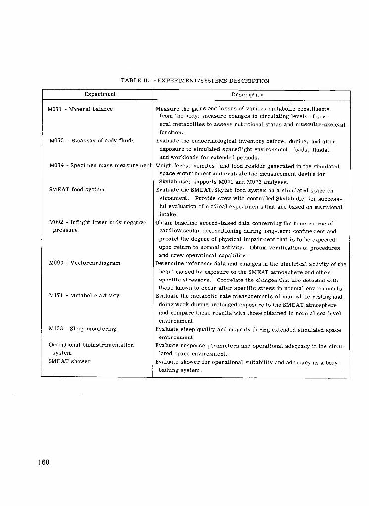
TABLE II. - EXPERIMENT/SYSTEMS DESCRIPTION
Experiment Description
M071 - Mineral balance Measure the gains and losses of various metabolic constituentsfrom the body; measure changes in circulating levels of sev-
eral metabolites to assess nutritional status and muscular-skeletal
function.
M073 - Bioassay of body fluids Evaluate the endocrinological inventory before, during, and after
exposure to simulated spaceflight environment, foods, fluids,and workloads for extended periods.
M074 - Specimen mass measurement Weigh feces, vomitus, and food residue generated in the simulatedspace environment and evaluate the measurement device forSkylab use; supports M071 and M073 analyses.
SMEAT food system Evaluate the SMEAT/Skylab food system in a simulated space en-vironment. Provide crew with controlled Skylab diet for success-ful evaluation of medical experiments that are based on nutritionalintake.
M092 - Inflight lower body negative Obtain baseline ground-based data concerning the time course ofpressure cardiovascular deconditioning during long-term confinement and
predict the degree of physical impairment that is to be expectedupon return to normal activity. Obtain verification of proceduresand crew operational capability.
M093 - Vectorcardiogram Determine reference data and changes in the electrical activity of theheart caused by exposure to the SMEAT atmosphere and other
specific stressors. Correlate the changes that are detected withthose known to occur after specific stress in normal environments.
M171 - Metabolic activity Evaluate the metabolic rate measurements of man while resting and
doing work during prolonged exposure to the SMEAT atmosphere
and compare these results with those obtained in normal sea level
environment.
M133 - Sleep monitoring Evaluate sleep quality and quantity during extended simulated spaceenvironment.
Operational bioinstrumentation Evaluate response parameters and operational adequacy in the simu-system lated space environment.
SMEAT shower Evaluate shower for operational suitability and adequacy as a bodybathing system.
160

TABLE II. - Concluded. EXPERIMENT/SYSTEMS DESCRIPTION
Experiment Description
SMEAT sleep restraint Evaluate the Skylab baseline sleep restraint and the alternate sleep
restraint for crew comfort and operational suitability.
Skylab urine system Evaluate and verify proposed in-flight procedures, ope'rational
suitability, and design adequacy of the Skylab urine system proto-
type.
Chamber environmental microbial Provide habitability, environmental aerosol, surface bioburden in-
monitoring formation.
SMEAT environmental noise Evaluate quantitatively and qualitatively the effects of continued ex-
posure to noise in the simulated space environment.
Atmosphere analyses Identify and quantify trace contaminants encountered during the
chamber test.
In-chamber CO 2 measurement Use and evaluate the Skylab CO2 /dewpoint monitor; obtain knowledge
and control of in-chamber CO 2 levels.
In-chamber CO measurement Provide capability for crew monitoring and warning of out-of-
tolerance in-chamber CO levels.
T003 - Aerosol analysis Measure and collect in-chamber aerosol particulate matter as a
function of time and location.
M487 - SMEAT habitability/crew Establish protocol and optimize subjective rating scales for elements
quarters of SMEAT/Skylab habitability and evaluate equipment use.
M151 - Time and motion study Evaluate crew activities during performance of operational and ex-
perimental tasks in the simulated space environment.
Skylab data acquisition simulation Evaluate mission rules and operations documents/Flight Operations
Division data evaluation and handling procedures in a real time
Skylab mission time frame with simulated manned space flight net-
work (MSFN) coverage.
SMEAT housekeeping Obtain information on frequency, duration, and crew acceptability of
housekeeping requirements during a simulated long-duration mission;
confirm predicted timelines for Skylab housekeeping activities.
SMEAT personal hygiene Evaluate personal hygiene activities in the simulated space environment
for extrapolation to the Skylab mission, crew evaluation of hygiene
hardware, and consideration areas.
M078 - Bone mineral measurement Measure any loss of bone mineral content during the simulated space
environment to provide baseline information for Skylab mission use -
prechamber and postchamber requirements only.
161

TABLE III. - VENT CHARACTERISTICS
Vent Vent Effluent Flow rate, Frequency Days per Velocity, Vent size, Remarks
number lb/sec mission m/sec in. diam.
6 Oxygen purge Oxygen 0.01 2 min/24 hr 14 to 18 300 0.21 No particulate
7 Hydrogen purge Hydrogen 0. 012 4 min/48 hr 14 to 18 300 0.21 No particulate
Water vapor .012
9 M512 Metallic vapors, nitrogen, 0.001 to 0.05 5 times total 6 to 10 300 4 Acceptable
oxygen, exothermic (over short
reaction products time intervals)
M479 Combustion products, 0.0001 to 0.1 37 times total 2 to 6 Particles - 0.3; 4 Testing
nitrogen, oxygen, water (over short Gasses - 300
vapor, particles time intervals)
10 MOL sieve Water vapor, oxygen, 0.01 average Continuous All 300 2 vents, 3 (each) No particulates
nitrogen, carbon dioxide (continuous) (15-min cycles) testing
13 EVA depress Oxygen, nitrogen, carbon 0. 14 average SL 1/2 - 1 1 to 2 300 2. 75 Acceptable
vent and hatch dioxide, water vapors for 30 sec SL 1/3 - 2
SL 1/4 - 2
19 Waste tank Water vapor, hydrogen, 16. 7 lb/day Continuous All Vapor - 300; 1 New filter
oxygen, urine, sweat, normal; 29. 4 Particles - 1-20 testing
food components, res- lb/day full
piration products, bio- contingency
cides
21 M092 LBNP Cabin atmosphere, sweat 0.05 9 times/mission 3 300 0.4 Acceptable
M171 Breath products Infinitesimal 2 to 3 times/day All 300 0. 4 Acceptable
22 SAL Cabin atmosphere 0.001 to 0.05 6 to 12 times/ All 300 0. 125 Acceptable
mission

TABLE IV. - MAJOR COMBUSTION PRODUCTS OF SOME SKYLAB MATERIALS
Test material Major combustion products
Polybenzimidazole (PBI) Carbon monoxide, carbon dioxide, nitrogen dioxide,
nitric oxide, cyanogen, methane, and benzene
Nylon fabric Nitrogen dioxide, nitric oxide, carbon monoxide,
carbon dioxide, methane, and ethylene
Paper Carbon monoxide, carbon dioxide, and methane
Rayon terry cloth Carbon monoxide, carbon dioxide, methane, ethylene,
normal butanol, acetylene, and ethane
Methyl vinyl silicone Carbon monoxide, carbon dioxide, methane, ethylene,
and normal butanol
Teflon sheet Carbon tetrafluoride, carbonyl fluoride, carbon
monoxide, and carbon dioxide (minor constituent)
TABLE V. - SKYLAB FLIGHT CREW
TRAINING PROGRAM (HR PLANNED)
Activity SLM-1 SLM-2 SLM-3
Briefings/reviews 450 450 450
Systems training 350 250 250
EVA/IVA 156 184 161
Medical 98 98 98
Simulators 695 695 695
Experiments 430 461 381
Total 2179 2138 2035
TABLE VI. - SUMMARY OF THE TEST PROGRAM REPORTS CLOSEOUT STATUS AS OF 9/1/72
FOR ORBITAL WORKSHOP
Items Test program Items Closed MDAC open NASA open NASA/MDAC
reports open
Combined subsystem 933 933 920 a10 1 2
C2F 2 experiment bench check 1 67 36 1 30 0
C2 F 2 stowage bench check 75 55 b 1 5 4 1
C2 F2 203 192 b 8 2 1
Delta C2 F 2 42 21 c 1 9 2 0
Delta C2 F2 dome locker 31 2 c 2 6 2 1
All systems test 119 119 116 3 0 0
aSubsystem TPR's are closed except for a few items waiting completion of inspection records.
bStowage bench check and C2 F2 items are open for decal changes, missing hardware, etc.
CDelta C2 F2 items were opened within the past few days and are still being worked.
163

TABLE VII. - TEST OBJECTIVES NOT YET SATISFIED
Subsystem Remaining components
open items to be qualified
Crew equipment 1 0
Ordnance 0
Caution and warning
Electrical power
Solar array system
Structures 3
Communication and data acquisition 0 2
Thruster attitude control system 0 4
OWS experiments 0 6
Environmental/thermal control 1 7
Habitability support system 6 10
TABLE VII. - LEAKAGE ALLOCATION SUMMARY
lb/day of oxygen/ lb/day of oxygen/
nitrogen at 5 psia nitrogen at 5 psia
during habitation during
storage
Allocations for component leakage
Total 3.513 3.617
Dumps and purges (HSS usage):
Waste processor (4 operations/day) 0. 037
Trash airlock (5 operations/day) .650
Liquid urine purge (3 operations/day) .020
Total 0. 707 0
Contingency (including leakage from welds
and other elements of basic structure)
Total 0.780 1.383
Total (lb/day) 5. 000 5. 000
ORIGINAL
164 oPR~ QU. I VW

TABLE IX. - WASTE TANK - TRASH DISPOSAL AIRLOCK PROBLEM SUMMARY
Problem Solution
Absolute pressure gage - failed Made more rugged; retested successfully
in first phases of vibration
testing
Outboard hatch - drifted from Tension strut was added; retested successfully
its exact center after cycling
due to brinnelling of aluminum
hub for antirotational bolt
Pressurization valve plug - plug Land was turned down to give clearance with
land galled causing valve bore; handle load reduced to acceptance
handle load increase, bore level; continued testing with no further problem
also galled
Inboard hatch latch - galling be- Solid film replaced with krytox grease; testing
tween latch eccentric and continued successfully
mating part due to lack of
proper lubricant caused ex-
cessive latch loads
TABLE X. - REFRIGERATION SYSTEM
System provides equipment for Temperature,oF
Frozen food -20 to +0
Food chilling +33 to +45
Water chilling +33 to +45
Urine chilling +59 (max)
Urine freezing -2. 5 (max)
165

TABLE XI. - FIRE SENSOR LOCATION AND READOUT LOCATION
Sensor location Readout location Fire location
Wardroom sensor 2 Control panel OWS crew quarters
Wardroom sensor 1 .Waste management compartment Control panelSleep compartment 1
Sleep compartment 2 Control
Sleep compartment 3 J
Experiment compartment 3 1Control panel OWS experiment compartmentExperiment compartment 2 JExperiment compartment 1 Control panel
Forward compartment 3 Control panel OWS forward compartmentForward compartment 2 Control panel
Forward compartment 1 J
TABLE XII. - OWS GENERAL ILLU-
MINATION SYSTEM PROVIDES
GENERAL ILLUMINATION AT
AVERAGE LEVELS
[System provides initial entry and
emergency mode illuminationof
0. 5 footcandle (min) in crew
quarters and forward compart-
ment]
Area Footcandle
(min)
NASA sleep compartment 4. 5
Wardroom 5.0
Head 9.0
Experiment compartment 5. 5
Forward compartment 1.0
166

TABLE XIII. - OWS STOWAGE LOCKERS NOT REVIEWED AT
HUNTINGTON BEACH (8/31/72)
[Those stowage lockers which have been reviewed and have open TPR
items against them at time of shipment are not included in this list.]
Stowage Reason for no review
lockers
D420 No flight data file maps, no ergometer restraints
D448 No triangle shoes
F507 No A9 locker contents
F517 No blood sample spacers, etc.
F519 No blood sample spacers, etc.
F567 Redesign ETC window bracket not available
F573 No ETC stowage locker
W703 No high school student experiment equipment
W704 Inadequate quantity of food supplements available
W714 Final flight entertainment equipment contents not available
W749 M487 flight hardware not available
W754 On-orbit configuration not reviewed (food cans plus IMSS)
W769 No fecal tracers
H810 No blood sample equipment
H820 Squeezer bag stowage so unacceptable needs complete rereview
H823 Urine bag dispenser locker not available
S901 No sleep restraints
S902 No sleep restraints
E610 Final flight biomedical equipment contents not available
E615 Final flight biomedical equipment contents not available
S903 No sleep restraints
S909 No triangle shoes
S921 No triangle shoes
S931 No triangle shoes
167

TABLE XIV. - STRUCTURES AND MECHANICAL SUBSYSTEM
SYSTEM PERFORMANCE SUMMARY
Component/subsystem Factor of safety,
actual minimum effectivea
Airlock module:
AM basic structure (STS, tunnel, trusses) 1.25
EVA hatch: compartment (including internal hatches) 2.15
Nitrogen bottles mounting 2.00
AM/OWS bellows 2.00
STS windows 3.79
Mechanisms (latches, etc.) 2.00
AM/MDA radiators b 1 3.00
Transportation and handling equipment (as affects b4. 00
flight hardware)
Apollo telescope mount deployment assembly:
ATM/DA basic structure b 5 . 0
Deployment mechanisms b 3 . 0
Rigidizing mechanisms b 5 . 0
FAS attachments b 8 . 0
Transportation and handling equipment (as affects b4. 0
flight hardware)
aEffective factor of safety defined here as factor of safety that will result in a
zero margin of safety: Effective factor of safety = Capability/Applied load.bNo structural verification tests.
168

TABLE XV. - INSTRUMENTATION AND COMMUNICATION SYSTEM PERFORMANCE SUMMARY FOR AM DATA SUBSYSTEM
Basic requirements Capability Verification
Monitor and process signals 575 Transducers and 250 signal conditioners All subsystem requirements have been verified
from experiments and provide outputs to approximately 1250 by analysis and test program which includes
module subsystems telemetry channels, 80 displays, and development, qualification, acceptance, and
25 C&W channels special functional compatibility and interface
Multiplex and encode data Programmer, interface box, and 25 multi- testing
from experiments and plexers provide 1298 analog and discrete SWS/STDN compatibility testing was performed
module for transmission channels, 1035 of which are recordable at GSFC
to STDN All testing has been completed except:
Record voice and data Each of three tape recorders provide 180 Mission support engineering, will be completed
minutes record capability with playback by April 1, 1973
in 8 minutes per recorder Intrasubsystem waveform, will be completed
VHF transmission link to One launch and three on-orbit transmitters by January 15, 1973
STDN via antennas which modulated by six different sources provide Tape temperature, will be completed by
provide coverage during launch and on-orbit coverage via discone March 1, 1973
all mission phases and UHF stub antennas; hardline cable Qualification of --
provides prelaunch data coverage PPO2 sensor, will be completed by November 7, 1972
TACS temperature sensor, will be completed by
October 31, 1972
TACS pressure sensor, will be completed by
October 20, 1972
OWS gas flowmeter, will be completed by April 13, 1973
Delta qualification of tape recorders, will be completed
by December 31, 1972
Systems acceptance of tape recorders, will be completed
at KSCby February 5, 1973

TABLE XVI. - SKYLAB SYSTEMS/OPERATIONS
COMPATIBILITY ASSESSMENT REVIEW
(SOCAR) PLAN REVIEW TOPICS
Systems design
Systems performance predictions
Systems operation constraints and limitations
Systems interfaces - functional
Waivers and deviations
Test and test anomalies
FMEA/SFP
Safety checklists
In-flight maintenance tasks
Contingency analyses
170


