V 2000HD - Screen Printing Equipment, Screen Printing ... Printers/01-08-043 V-2000HD Manua… ·...
16
V-2000HD Assembly, Operating, and Maintenance Instructions for all V-2000 rotary presses. Contents Page# • Introduction– Please Read Thoroughly 2 • Safety Information 3 • Overall View 4 • Printer Assembly 5-7 • Printhead/Extension Arm Pics & PN 8 • Micro Registration Adjustment 9 • Level & Off Contact Adjustment 10 • Pallet Assembly 11 • Pallet Leveling 12 • Detent Wheel & Service Pan 13 • Lubrication / Maintenance 14-15 • 01-00-005B / 01-00-015 Warranty 16 Doc # 01-08-043E Vastex E-mail assistance Purchasing & Product Info: [email protected] Electrical Support: [email protected] Tech Support, Mechanical Setup, and Operation: [email protected] Screen Printing Issues & Support: [email protected] Serial Number: (Please log your machine's serial number and date of purchase for future reference.) Date:____/____/______ VTX Original Instructions Vastex International, Inc. 1032 N. Irving St. Allentown, Pa. 18109 USA Phone# 610 434-6004 Fax# 610 434-6607 Web Site www.vastex.com Authorized Representative in Europe: Certification Experts BV Nieuwstad 100 1381 CE Weesp, The Netherlands Tel : + 31 (0) 294 – 48 33 55 Fax : + 31 (0) 294 – 41 46 87 Year of Manufacture: 20____
Transcript of V 2000HD - Screen Printing Equipment, Screen Printing ... Printers/01-08-043 V-2000HD Manua… ·...

V-2000HD Assembly, Operating, and Maintenance Instructions for all
V-2000 rotary presses.
Contents Page#
• Introduction– Please Read Thoroughly 2
• Safety Information 3
• Overall View 4
• Printer Assembly 5-7
• Printhead/Extension Arm Pics & PN 8
• Micro Registration Adjustment 9
• Level & Off Contact Adjustment 10
• Pallet Assembly 11
• Pallet Leveling 12
• Detent Wheel & Service Pan 13
• Lubrication / Maintenance 14-15
• 01-00-005B / 01-00-015 Warranty 16
Doc # 01-08-043E
Vastex E-mail assistance Purchasing & Product Info: [email protected] Electrical Support: [email protected] Tech Support, Mechanical Setup, and Operation: [email protected] Screen Printing Issues & Support: [email protected]
Serial Number:
(Please log your machine's serial number and date of purchase for future reference.)
Date:____/____/______ VTX
Original Instructions
Vastex International, Inc. 1032 N. Irving St. Allentown, Pa. 18109 USA Phone# 610 434-6004 Fax# 610 434-6607 Web Site www.vastex.com Authorized Representative in Europe: Certification Experts BV Nieuwstad 100 1381 CE Weesp, The Netherlands Tel : + 31 (0) 294 – 48 33 55 Fax : + 31 (0) 294 – 41 46 87
Year of Manufacture: 20____

Introduction: Thank you for purchasing your printing equipment from Vastex International Inc.
Vastex has been designing and building printing equipment since 1960. We have knowledge and expe-
rience, and are proud to supply the printing industry with quality equipment at an affordable price. You
can be confident your purchase will give you years of trouble free service.
Features: • Micro Registration
• Wrench-less Adjustments
• Steel pallets with rubber tops
Options: • Additional color and station upgrade packages
• Unique, fast, numbering system attachment
• Super heavy duty print arms
(hold up to 50lbs.[22.7kg] )
• Pallets– Request a Pallet Spec Book
• All heads down
• Upgradeable (Available up to 10x10)
• Tabletop units available
Placing this equipment into service: To place your press into service —
1.) Review the photograph on page 4 to familiarize yourself with the parts of the press.
2.) Follow the instructions on pages 5 through 7.
3.) If necessary to make fine adjustments to your press, see pages 8 through 13.
Operating this equipment: To operate your press —
1.) Clamp your first screen into head #1.
2.) Repeat for additional screens, using additional heads.
3.) Place garment in pallet #1.
4.) Lower print head and squeegee ink through screen.
5.) Raise print head. For one-color printing, load new, blank garment and repeat steps above.
6.) For multi-color printing, rotate the pallet to print head #2 and repeat steps above until all colors are printed.
7.) If any adjustments to the print heads need to be made, refer to the instructions in this manual.
Safe handling, transport, and storage of the press: Your press is designed to be inherently safe under all normal conditions. When handling or transporting your press, be
aware of the weight of your unit and have an appropriate number of people to lift the weight safely:
V2HD-44: 400 lbs (182 kg) V2HD-88: 750 lbs (340 kg) V2HD-1010: 1075 lbs (488 kg)
V2HD-46: 473 lbs (214.5 kg) V2HD-66: 550 lbs (250 kg)
If your press is to be moved or transported regularly, it is recommended that you purchase the optional casters.
In the event of an accident or breakdown: In the unlikely event that a part of your press breaks, or if your press does not seem to be operating normally and the instruc-
tions in this manual do not correct the issue, do not continue using your press. Contact Vastex for assistance in repairing
your press.
Safety during maintenance or while making adjustments: • When cleaning or lubricating your press, make sure that nobody in the work area is close enough to cause any part of
the press to move unexpectedly.
• If gas springs are removed for inspection or replacement, be aware that they are under tension in the compressed posi-
tion and take appropriate precautions to let them extend fully before removing.
• Do not remove springs unless under the specific direction of Vastex customer service.
• Side clamps, removable or fixed
• Stand (for tabletop version)
• Locking casters and levelers
• Service Pan (for extra storage) w/ locking casters
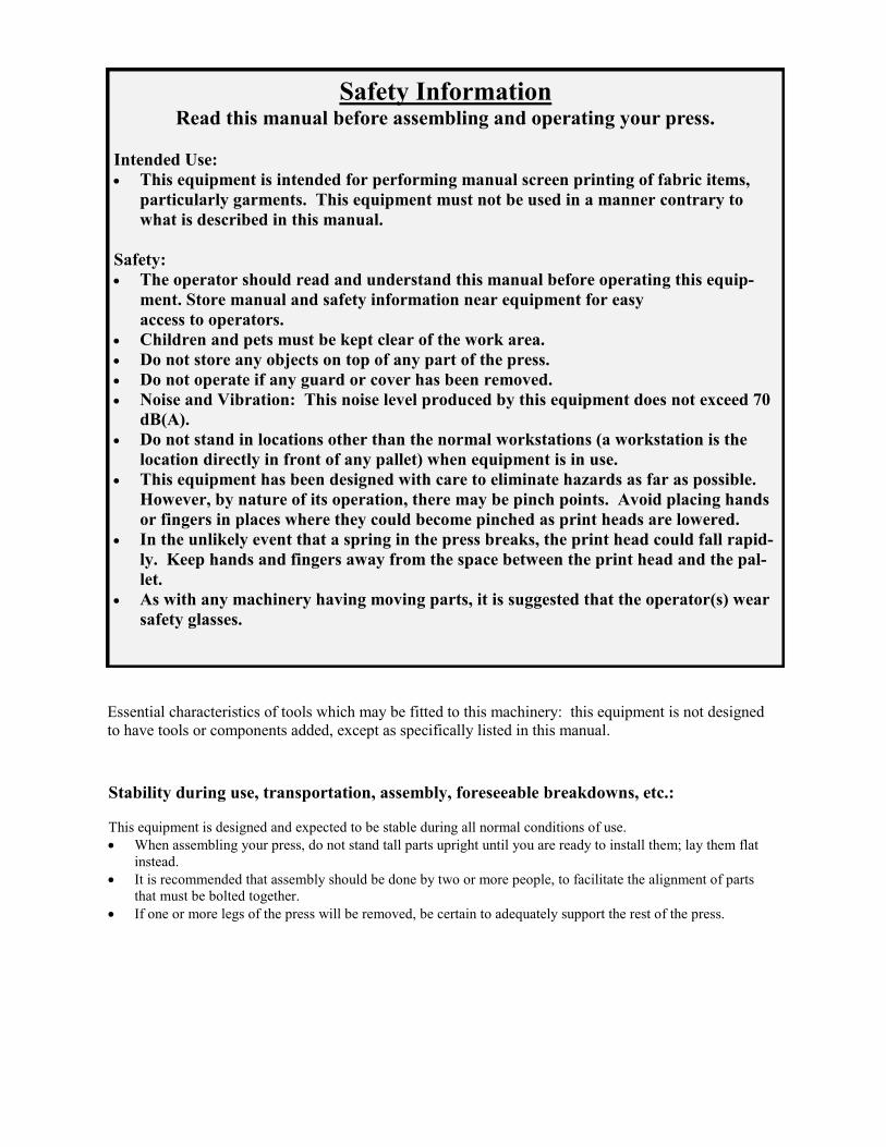
Safety Information Read this manual before assembling and operating your press.
Intended Use:
• This equipment is intended for performing manual screen printing of fabric items,
particularly garments. This equipment must not be used in a manner contrary to
what is described in this manual.
Safety:
• The operator should read and understand this manual before operating this equip-
ment. Store manual and safety information near equipment for easy
access to operators.
• Children and pets must be kept clear of the work area.
• Do not store any objects on top of any part of the press.
• Do not operate if any guard or cover has been removed.
• Noise and Vibration: This noise level produced by this equipment does not exceed 70
dB(A).
• Do not stand in locations other than the normal workstations (a workstation is the
location directly in front of any pallet) when equipment is in use.
• This equipment has been designed with care to eliminate hazards as far as possible.
However, by nature of its operation, there may be pinch points. Avoid placing hands
or fingers in places where they could become pinched as print heads are lowered.
• In the unlikely event that a spring in the press breaks, the print head could fall rapid-
ly. Keep hands and fingers away from the space between the print head and the pal-
let.
• As with any machinery having moving parts, it is suggested that the operator(s) wear
safety glasses.
Essential characteristics of tools which may be fitted to this machinery: this equipment is not designed
to have tools or components added, except as specifically listed in this manual.
Stability during use, transportation, assembly, foreseeable breakdowns, etc.:
This equipment is designed and expected to be stable during all normal conditions of use.
• When assembling your press, do not stand tall parts upright until you are ready to install them; lay them flat
instead.
• It is recommended that assembly should be done by two or more people, to facilitate the alignment of parts
that must be bolted together.
• If one or more legs of the press will be removed, be certain to adequately support the rest of the press.

V-2000HD Overall View V
-2000H
D O
ver
all
Vie
w
VR
-AR
M-S
Ro
tor
Arm
Ass
em
bly
V
2P
-15
17
15"X
17"
Sta
nd
ard
Pal
let
asse
mb
ly.
Det
ent
Ass
em
bly
VC
-HU
B-4
,6,8
, o
r 10
C-H
ub
VR
-HU
B-4
,6,8
, o
r 10
Ro
tor
Hub
V-S
TA
ND
(st
and
ass
em
bly
4,6
,8 c
olo
r p
ress
) (p
ictu
red
)
V-S
TA
ND
-10
(st
and
ass
em
bly
10
co
lor
pre
ss)
VC
-EX
-HD
Exte
nsi
on A
rm H
eav
y D
uty
V
C-P
H-R
C P
rint
Hea
d R
ear
VC
-PH
-SC
Pri
nt
Hea
d S
ide
Cla
mp
(o
pti
onal
)
*V
C-E
X-S
HD
Exte
nsi
on A
rm S
up
er H
eav
y D
uty
.
(op
tio
nal
, re
quir
ed f
or
VN
S n
um
ber
ing s
yst
em
)

2) Take press off of skid, by removing the lag bolts
at the feet and carefully sliding the press off the
skid and onto the shop floor.
Some accessories
are packed with
the press.
3) Install your rotor arms. Be sure to put the arms into the correct numbered positions.
Each arm is packed with a pallet attached. Install the rotor arm as shown below. Two hooks hold the
Rotor Arm in place before hardware is installed. Install (4) gold colored washers and (4) 3/8” bolts on
each arm. Tighten these bolts Very Well.
1) Remove straps, sides of crate, and shrink wrap
from around the press. Remove lag bolts holding
the rotor arms to skid and unpack boxes under
press.
Note: Report any box
damage to the driver and
note it on the ticket before
signing. If hidden damage
is found, report it to the
trucking company right
away and save the pack-
aging.
Printer Assembly

4) Install the gas springs, found in print
head box, with the number 1 head and the
rotor arm bolts. There are 4 slots on each
side to choose. Be sure the barrel is in the
up position and for starters use the slots
shown to the right.
Note: The gas spring can
be put into any slots to get
the “feel” you like. Be sure
to install with the barrel up
as shown.
5b) Position the large holes in the print head back plate
over the mounting bolts and slide down into the slots.
Be sure the head is slid all the way down in the slots.
Fully tighten only the Locking Levers of the #1 Print
Head. The remaining Print Heads will be tightened af-
ter the Print Heads are leveled. The locking lever han-
dle can be pulled out to allow rotation to another posi-
tion, release to engage for locking.
5a) Installing the Print Heads onto the Swivel
Arms. One print head has been leveled and #1
to match the swivel and extension arm #1. To
install the Printheads, pull the mounting bolts
forward.
Swivel Arm
Print Head
Mounting Bolts
Off Contact Locking Lever
Extension Arm
Printer Assembly
Print Head Installed
Print Head Mounting Bolts
Off Contact Locking Lever
Print Head Back Plate
Mounting Holes / Slots
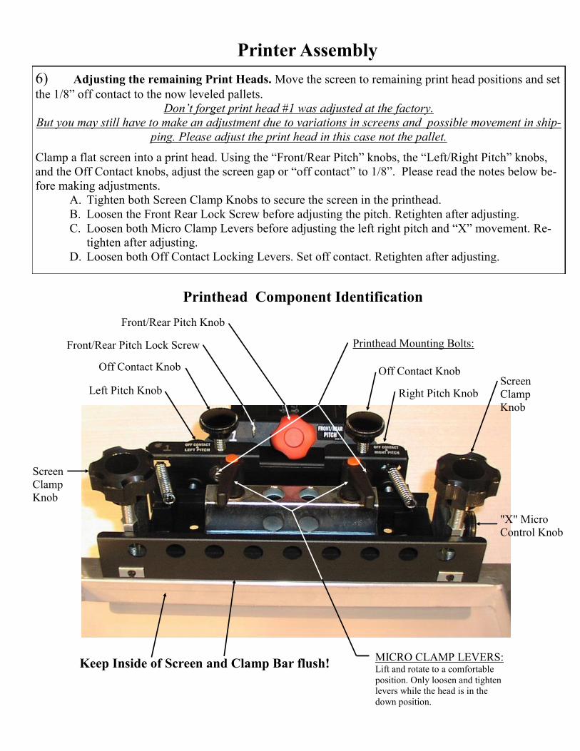
6) Adjusting the remaining Print Heads. Move the screen to remaining print head positions and set
the 1/8” off contact to the now leveled pallets.
Don’t forget print head #1 was adjusted at the factory.
But you may still have to make an adjustment due to variations in screens and possible movement in ship-
ping. Please adjust the print head in this case not the pallet.
Clamp a flat screen into a print head. Using the “Front/Rear Pitch” knobs, the “Left/Right Pitch” knobs,
and the Off Contact knobs, adjust the screen gap or “off contact” to 1/8”. Please read the notes below be-
fore making adjustments.
A. Tighten both Screen Clamp Knobs to secure the screen in the printhead.
B. Loosen the Front Rear Lock Screw before adjusting the pitch. Retighten after adjusting.
C. Loosen both Micro Clamp Levers before adjusting the left right pitch and “X” movement. Re-
tighten after adjusting.
D. Loosen both Off Contact Locking Levers. Set off contact. Retighten after adjusting.
Printer Assembly
Printhead Mounting Bolts:
Screen
Clamp
Knob
Left Pitch Knob Right Pitch Knob
Front/Rear Pitch Lock Screw
Screen
Clamp
Knob
MICRO CLAMP LEVERS: Lift and rotate to a comfortable
position. Only loosen and tighten
levers while the head is in the
down position.
Front/Rear Pitch Knob
Keep Inside of Screen and Clamp Bar flush!
Off Contact Knob Off Contact Knob
"X" Micro
Control Knob
Printhead Component Identification

Gro
und
Pla
te
05-0
5-0
10-1
VC
-EX
-HD
Vast
ex V
-2000H
D
Pri
nt
hea
d/E
xte
nsi
on
Arm
Sp
ring,
Mic
ro
(3)
04-0
5-0
70
Mic
ro W
ear
Str
ip
(4)
05-0
5-0
17
Cla
mp
Kno
b
(2)
04-0
5-1
07
Cla
mp
Bar
05-0
5-0
22-0
Fo
rk R
etai
ner
(2)
05-0
5-0
26-0
(Mic
ro K
no
b)
Kno
b w
/ S
tud
3/8
-16
x 2
1/4
(3)
04-0
5-1
50
Scr
een C
lam
p
Wel
dm
ent
(2)
05-0
5-0
13-1
Mic
ro L
ock
Cla
mp
Lev
ers
(2)
04-0
5-1
45
Scr
een C
ab
05-0
5-0
11-1
Vastex V-2000HD Print head/Extension Arm
VC
-PH
-RC
Sp
ring,
Mic
ro
Kno
b
(3)
04-0
5-2
08
Kno
b,
Off
Co
nta
ct
(2)
04-0
5-1
55
Sp
ring
(2)
04-0
5-0
72
Reg
istr
atio
n B
ar
05-0
4-0
05
Sup
po
rt,
Reg
istr
atio
n
Bar
Mo
unt
05-0
4-0
21
Sw
ivel
Arm
05-0
5-0
05-1
Mo
vin
g P
oin
t
Sp
ring B
rack
et
05-0
5-0
06
Gas
Sp
rin
g
04-0
0-0
01
Gas
Sp
rin
g P
in
05-0
5-0
18
Kno
b,
Pit
ch A
dj.
04-0
5-1
91
Lo
ckin
g L
ever
Off
Co
nta
ct
04-0
5-3
07

Micro Registration Adjustment Instructions
Vastex micro-registration is standard with every V-2000 screen printer. It uses three control knobs, two micro
clamp levers, and three return springs for movement control. A set of centering sites is used to start at a zero point.
A total of 1/2" movement is available in the "X" direction and also in the "Y" direction
• Rotating the screen can be done by turning one of the "Y" micro control knobs. The pivot point for rotation is
the tip of the other "Y" micro control knob.
• The micro clamp levers must be loosened (1/4-1/2) turn only, before turning the control knobs.
Start each job with the centering sites lined up. This ensures you will have all the available adjustment.
To Move the Screen Left to Right 1) Loosen the two micro clamp levers (1/4-1/2)
turn
2) Turn the "X" micro control knob clockwise
(looking at the head) to move the screen to the
right. Turn it counterclockwise to move the
screen to the left.
3) Tighten the micro clamp levers and check the
position. Repeat the above steps if necessary
until the desired position is achieved.
Note: The micro clamp levers may be lifted and
rotated to any position desired. They must be
down to be loosened or tightened.
To Move the Screen Front to Back or Rotate 1) Loosen the two micro clamp levers (1/4-1/2) turn.
2) Turn both "Y" micro control knobs clockwise (looking
at the head) to move the screen toward you. Turn them
counterclockwise to move the screen away from you.
Turn one or the other to rotate the screen.
3) Tighten the micro clamp levers and check the position.
Repeat the above steps, if necessary, until the desired
position is achieved.
Centering sites
"X" Micro
Control Knob
Micro Clamp Levers
"X" Direction
"Y" Direction
Rotate
"Y" Micro Control Knob "Y" Micro Control Knob

Level & Off Contact Adjustments
The Vastex V-2000 comes standard with 6-way level adjustments.
A. Tighten both Screen Clamp Knobs to secure the screen in the printhead.
B. Loosen the Front Rear Lock Screw before adjusting the pitch. Retighten after adjusting.
C. Loosen both Micro Clamp Levers before adjusting the left right pitch and “X” movement. Re-
tighten after adjusting.
D. Loosen both Off Contact Locking Levers. Set off contact. Retighten after adjusting.
Refer to Printhead Component Identification section for descriptions of knobs and levers.
Adjusting the Screen Off Contact: • Be sure the screen is clamped tightly and both the
Micro Clamp Levers and Off Contact Locking Levers
are tight.
• There are two sets of adjustments that affect the
off contact.
(1) The Off Contact Knobs control left to right level as
well as screen off contact. Loosen slightly the Off
Contact Locking Levers. Adjust the left / right pitch
knob as needed. Do one side at a time while observing
movement.
(2) The Pitch Knob controls the front to back level. The
Pitch Lock Screw must be loosened to make this ad-
justment. Do not over tighten.
Follow these steps for each head. Head #1 is factory set.
1) Lower the print head to be leveled. Be sure all four
locking levers and the pitch screw are tight.
2) If the screen is touching the pallet in one corner or
more loosen one Off Contact Locking Lever and turn
the Off Contact Knobs as needed. Adjust each side
until the screen is level left to right and about 1/8” off
the pallet. If the front of the screen is contacting the
pallet it may be necessary to adjust pitch before off
contact can be achieved.
3) Adjust the front to rear level by unlocking the Pitch
Locking Screw and turning the Pitch Knob. Clock-
wise will lift the front of the screen and counter clock-
wise will lower. (It may be necessary to repeat step 2
after adjusting the front to rear pitch.)
Be sure to tighten all four levers and pitch lock screw before
printing.
Fro
nt/
Rea
r P
itch
Off
Co
nta
ct
Left
/Rig
ht
Pit
ch
Off Contact
Locking Lever
Micro Clamp
Locking Lever
Pitch Lock Screw

Note: All pallets have been preassembled and leveled at the factory since summer of 2010.
Pallet Assembly
The following procedure is for changing pallet
tops, and/or pallet arms.
1) Remove screws from neck guide
-Using Flat Blade Screwdriver or
1/4” nut driver
2) Install neck guide using screws from step 1
-Tighten with Flat Blade Screw driver or
1/4” nut driver
6) Install Corner Tab as shown 5) Install Corner Nut and knob as shown.
Add grease (included) to thread of knob.
2”
3) Install (4) 3/8-16 x 3” bolts, (8) 3/8” washers,
and (8) 3/8-16 nuts as shown.
-Tighten bottom nut with 9/16” wrench.
-Set height as shown.
7) Install Clip as shown
Clip
4) Install Pallet arm, (4) 3/8” washers,
and (4) 3/8-16 nuts, as shown.
-Tighten with (2) 9/16” wrenches
Grease Here

Note: All pallets have been preassembled and leveled at the factory since summer of 2010.
If pallet leveling is required follow procedure below
The objective is: To make the pallets and print heads aligned and parallel with approximately 1/8 off con-
tact.
You do not need to use a bubble level on the pallets. You can level the machine to the floor if you like, but
the important thing is the pallets need to be parallel to the screen mounted in the print head and centered over
the rotor arms.
Remember print head #1 was adjusted at the factory. In the next few sections we will use print head #1 to
adjust any pallets needing leveling then use the pallets to adjust the remaining print heads.
1) Place your best flat aluminum
screen into head #1 and lower it over
pallet #1. Align side of screen with
side of pallet as shown. Do not remove
this screen until all pallets have been
set.
Be sure the gas spring is in a position
that allows the screen to stay down by
itself.
Observe the “off contact” in all four
corners of the pallet. It should be ap-
proximately 1/8”.
2) Lower the # 1 print head with the already installed screen over another pallet. The pallet leveling
nuts should be finger tight while setting side alignment and off contact. Align the side of the pallet to the
side of screen. Do not move the screen to the pallet, move the pallet to the screen. Adjust the nuts at the
bottom of the pallet leveling bolts to set the off contact to approximately 1/8”. When 1/8” off contact has
been achieved at all corners and the pallet and screen sides are flush proceed to tighten all pallet nuts. It is
important that a good quality flat screen is used while making these adjustments. Repeat for all remain-
ing pallets.
These nuts should have been
tightened at pallet assembly.
Align side of screen with side
of # 1 pallet.
Pallet leveling bolts & nuts
1/8 between screen and
pallet at all corners
#1 Rotor Arm, Pallet, & Print Head Shown Above
IMPORTANT NOTE: It is best to line up the inside of the screen with the front of the clamp
bar any time you install screens in your V-2000 rear clamps.
Pallet Leveling

Detent Wheel Adjustment
Detent Rocker Assembly
The Detent Wheel is adjustable. To adjust;
Loosen the nut, with (2) 9/16 wrenches.
Move the wheel up, to increase, or down, to
decrease, the Rotor Arm holding pressure.
The Detent Rocker is used to achieve a repeatable position for the pallet under your
flash. It can be set to lock the arm very firmly, loosely, or can be disabled altogether to
remove the indexing feature.
Service Pan and Wheels (optional)
Wheels are installed with 1/2” hardware and foot brace.
The brace goes under the foot and the wheel goes through
both the foot and brace (shown below). Use the serrated
1/2” locknuts to attach the wheels to the feet.
Service Pan is installed by laying the Pan on the floor and
rolling the machine over the Service Pan. The Service Pan
can also be installed by removing one wheel (must have
two people for this). Line it up with the holes on the inside
of the press’ feet. Lift the pan and install 1/2” hardware,
using the flat washer on the bottom of the Service Pan
The Detent Wheel is adjustable. To adjust;
Loosen the lock nut with a 9/16” wrench.
Turn the screw out to increase or in to de-
crease holding pressure. Retighten locking
nut after adjusting.
V2HD Printers built before Jan. 1, 2012 V2HD Printers built after Jan. 1, 2012
Lock Nut
Adjuster Screw
Lock Nut
Doc # 01-08-034A
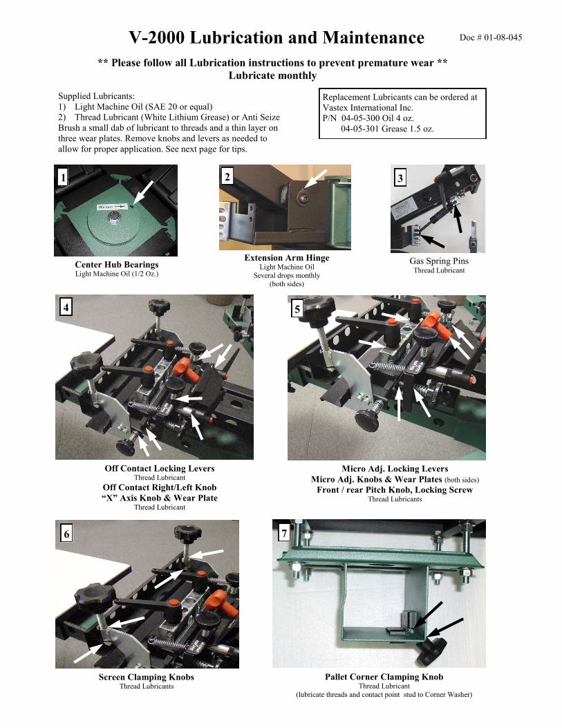
** Please follow all Lubrication instructions to prevent premature wear **
Lubricate monthly
V-2000 Lubrication and Maintenance
Extension Arm Hinge Light Machine Oil
Several drops monthly
(both sides)
2
Center Hub Bearings Light Machine Oil (1/2 Oz.)
1
Gas Spring Pins Thread Lubricant
3
Off Contact Locking Levers Thread Lubricant
Off Contact Right/Left Knob
“X” Axis Knob & Wear Plate Thread Lubricant
4
Micro Adj. Locking Levers
Micro Adj. Knobs & Wear Plates (both sides)
Front / rear Pitch Knob, Locking Screw Thread Lubricants
5
Screen Clamping Knobs Thread Lubricants
6
Pallet Corner Clamping Knob Thread Lubricant
(lubricate threads and contact point stud to Corner Washer)
7
Supplied Lubricants:
1) Light Machine Oil (SAE 20 or equal)
2) Thread Lubricant (White Lithium Grease) or Anti Seize
Brush a small dab of lubricant to threads and a thin layer on
three wear plates. Remove knobs and levers as needed to
allow for proper application. See next page for tips.
Replacement Lubricants can be ordered at
Vastex International Inc.
P/N 04-05-300 Oil 4 oz.
04-05-301 Grease 1.5 oz.
Doc # 01-08-045

V-2000 Lubrication and Maintenance
Cleaning • Clean your machine on a daily basis or between each job. Particularly removing lint around
moving points and adjustment areas. A clean machine is more likely to be maintained proper-
ly than a messy one. Any solvents can be used on the pallet tops for cleaning. The painted
surfaces should be cleaned with detergent, like a glass or multi-surface cleaner, to remove lint
and dust. Mineral spirits can be used to remove spilled inks. Avoid spraying pallet adhesive
on the gas springs to ensure their longevity.
Inspection • Inspect your machine on a monthly basis for untimely wear or any other signs of problems.
This can be done while lubricating and should take no more than a few minutes. Finding a
problem early can reduce the cost of downtime and repair.
Notes:

Vastex Warranty Doc#01-00-005B Revised 04/10/12
(1.) Vastex, hereinafter referred to as “seller” warrants only to its original “purchaser”, who holds a copy of the original invoice and is the original end user of the equipment in question, its new equipment against defects in materials or workmanship on a pro-rated basis. Warranty period begins from date of shipment to the buyer and will only apply to customers paid in full. Warranty periods are as follows: one (1) year for E-1000, three (3) years for all other complete machines (including F-Flash), fifteen (15) years for infrared heaters (excluding F-Flash) installed by Vastex in a new dryer, three (3) years for replacement infrared heaters, and one (1) year for replacement parts. Rubber blankets, light bulbs and glass on exposure units are particularly subject to wear while in use. Wear is not covered by this warranty but as stated above only manufacturers defects are covered. All sales made through Vastex dealers must be certified by that dealer before a warranty replacement is issued. (2.) This warranty is expressly contingent upon the buyer delivering to seller, at the address below, with all transportation charges prepaid, the part or parts claimed to be
defective within the above mentioned warranty periods stated in paragraph one. The defective part or parts will be repaired or replaced at the discretion of Vastex Internation-
al, Inc. If the equipment in question is less than one (1) year old, it will be shipped to the customer at no charge, with an RGA issued by Vastex for the defective part. The defec-
tive part must be shipped back to Vastex freight prepaid within 30 days or the account will be billed. If the equipment is more than a year old, the part will be shipped after we
receive the defective part. If it’s necessary to expedite the movement of parts and to minimize down time to the buyer, the replacement part shall be supplied on a C.O.D. basis.
If testing and analysis of said part by the seller or its supplier discloses that said part is defective, the cost of said part will be refunded to the buyer on a prorated basis. (3.) Except as otherwise provided herein, the equipment is being sold “as-is”. Final determination of the suitability of the equipment for the use contemplated by the buyer, is the sole responsibility of buyer, and seller shall have no responsibility in connection with the suitability. (4.) All warranties implied by law, including the implied warranties of merchantability and fitness are hereby limited to workmanship and defective parts to a warranty period stated in paragraph one. The express warranty and remedies contained herein and such implied limited warranties are made solely to the sole warranties and remedies and are in lieu of all other warranties, guarantees, agreements, and other liabilities, whether express or implied, and all other remedies for breach of warranty or any other liability of seller, in no event shall seller be liable for consequential damages.
No person, agent, distributor, or service representative is authorized to change, modify or extend the terms hereof in any manner whatsoever. These terms and conditions are an essential part of the transaction between the parties and constitute the entire agreement between them with respect to the same. Some states do not allow limitation on how long an implied warranty lasts of the exclusion or limitation of incidental, or consequential damages, so the above limitation may not apply to you. This warranty gives you specific legal rights, and you may also have other rights which vary from state to state. Infrared heaters are the only replacement parts covered for a period of (3) years from date of shipment and contingent to receipt of payment in full.
Electrical components cannot be returned once installed unless proven defective. Please refer to doc. 01-00-015 for specific terms and conditions of sale and the limited warranty. Please refer to doc. 01-00-017 for V-2000HD printer warranty.
Updates: V1000 to 3 year warranty 01/09/12, Heater warranty to 15 years 01/02/2012. ---------------------------------------------------------------------------------------------------------------------------------------------------------------------------------------------------------------------
TERMS AND CONDITIONS OF SALE AND LIMITED WARRANTY Doc.#01-00-015
1. Buyer’s order will constitute an offer in accordance with the terms hereof and such offer, upon acknowledgment of Seller, will constitute the agreement between Buyer and Seller.
Buyer’s order after such acknowledgment by Seller will not be subject to cancellation, change or reduction in amount, or suspension by Buyer of deliveries, unless prior to such action Buyer has obtained Seller’s written consent. Notwithstanding anything to the contrary in Buyer’s Purchase Order or other communications, the parties agree to be bound by these Terms and Conditions. Acceptance of the product by the Buyer shall be deemed to constitute unconditional acceptance of these Terms and Conditions.
2. Any of these terms, conditions and provisions of Buyer’s order which are inconsistent with Seller’s acknowledgment and these Terms and Conditions of Sale shall not be binding on the Seller and shall be considered not applicable to any sale so made. No waiver, alteration or modification of any of the provisions on either side of the document shall be binding upon Seller unless agreed to in writing by Seller.
3. (a) All prices are F.O.B. Seller’s Plant and method of delivery and routing shall be at Seller’s discretion, unless specifically otherwise stated herein. Notwithstanding any agreement to pay freight, delivery of products purchased hereunder to a common carrier or licensed trucker shall constitute delivery to Buyer and be determinative of the date and time of shipment and all risk of loss or damage in transit shall be borne by Buyer. If the Buyer fails to accept the goods from the common carrier or licensed trucker, the Seller shall be entitled to claim payment from the Buyer. Seller shall arrange for storage, the risk and the cost, including insurance costs, to be borne by the Buyer (and Buyer agrees to pay such amounts upon demand) except if the failure to accept delivery is due to any of the exceptions noted in Paragraph 4.
(b) Terms of payment shall be as stated on invoice. 4. It is understood that deliveries will be made in accordance with Seller’s regular production schedule. Every reasonable effort will be made to meet the Buyer’s required delivery
dates but Seller will not be liable for damages or be deemed to be in default by reason of any failure to deliver or delay in delivery due to any preference, priority, allocation or allotment order issued by the Government, whether Federal, State or local, or causes beyond its control including but not limited to, Acts of God or a public enemy, acts of Govern-ment, fires, floods, epidemics, quarantine restrictions, strikes, lockouts, freight embargoes, severe weather, unavailability of materials or shipping space, delays of carriers or sup-pliers or delays of any subcontractors. Should delay in delivery be caused by any of the circumstances mentioned in this paragraph, such extension of the delivery period shall be granted as is reasonable under the circumstanced of the case. Should delay be caused by an event not specifically mentioned in this paragraph, damages will be limited to cancella-tion of the purchase order without penalty, and refund of any monies deposited or prepaid on the purchase order with no liability for any consequential or incidental damages.
5. Seller reserves the right to increase the prices prior to Seller’s acceptance of order and/or after expiration of any price quoted by Seller. 6. Unless otherwise stated in writing, Seller’s prices do not include sales, excise, value-added or other taxes. Consequently, in addition to the price specified herein, the amount of any
present or future sales, use, excise, value-added or other tax applicable to the manufacture, sale, purchase or use of the products hereunder shall be paid by Buyer, or in lieu thereof, Buyer shall provide Seller with a valid tax exemption certificate acceptable to the taxing authorities.
7. Seller reserves the right, at any time, to revoke any credit extended to Buyer because of Buyer’s failure to pay for any products when due or for any other reason deemed good and sufficient by Seller and in such event, all subsequent shipments shall be paid for prior to at delivery at Seller’s option.
8. (a) SELLER’S LIABILITY SHALL BE LIMITED TO SELLER’S STATED SELLING PRICE PER UNIT OF ANY DEFECTIVE GOODS AND SHALL IN NO EVENT IN-CLUDE BUYER’S MANUFACTURING COSTS, LOST PROFITS, GOODWILL, OR ANY OTHER SPECIAL, INDIRECT, INCIDENTAL OR CONSEQUENTIAL DAMAGES, ARISING OUT OF THE AGREEMENT, THIS CONTRACT, THE SALE OF THE PRODUCTS TO THE BUYER OR THE USE OR THE PERFORMANCE OF THE PRODUCTS. Seller may at its discretion repair, replace or give the Buyer credit (pro-rated) for such defective products.
(b) Notwithstanding anything herein to the contrary, Seller shall have no liability for alleged defects with the products which are not specified in written notice from the Buyer to the Seller within thirty-six (36) months from the date of shipment of machines. Seller shall pass to Buyer any warranty received by Seller from the manufacturer of Limited Life Components, which in most cases is 12 to 18 months.
(c) Seller shall have no liability under this Limited Warranty unless Buyer has paid in full for the products. Further, this Limited Warranty is expressly contingent on Buyer’s deliv-ery to Seller, all costs prepaid, the defective part(s) within thirty-six (36) months of shipment to Buyer, together with a written statement specifying the alleged defect(s). Any replacement part(s) shall be shipped to Buyer on a C.O.D. basis.
(d) SELLER SPECIFICALLY EXCLUDES ALL WARRANTIES, EXPRESSED, IMPLIED OR OTHERWISE, EXCEPT AS STATED EXPLICITLY IN THESE TERMS AND CONDITIONS OF SALE. SELLER DISCLAIMS THE WARRANTY OF MERCHANTABILITY AND FITNESS FOR A PARTICULAR PURPOSE.
9. The remedies herein reserved by Seller shall be cumulative and in addition to any other legal remedies. No waiver of a breach of any portion of this contract shall constitute a waiver of continuing or future breach of such provision or of any other provisions hereof.
10. These Terms and Conditions constitute the entire agreement of the parties. No amendments, changes, revisions or discharges hereof in whole or in part shall have any force or effect unless set forth in writing and signed by the parties hereto. This contract shall not be assignable by Buyer voluntarily by operation of law or otherwise without Seller’s writ-ten consent.
11. This contract shall be governed and shall be construed according to the domestic laws of the Commonwealth of Pennsylvania. 12. Anything herein to the contrary notwithstanding, any action for alleged breach by Seller of the contract between the parties, including but not limited to any action for breach of the
warranties herein set forth, shall be barred unless commenced by Buyer within one (1) year from the date such cause of action accrued. 13. This agreement shall inure to the benefit of and be binding upon the parties hereto, their respective successors and permitted assigns. 14. All notices required by this contract to be given by either party shall be sent in writing or by facsimile and shall be addressed to the last known address of such other
party. Notices shall be deemed to have been received on the fifth business day following deposit in the mail.


![3D SCREEN PRINTING MASS PRODUCTION OF ... - · PDF file3D SCREEN PRINTING MASS PRODUCTION OF ... [HB] 3D Metal Printing - Binder Jetting approach ... 2D screen printing is an established](https://static.fdocuments.net/doc/165x107/5aa545cf7f8b9ab4788cecdc/3d-screen-printing-mass-production-of-screen-printing-mass-production.jpg)