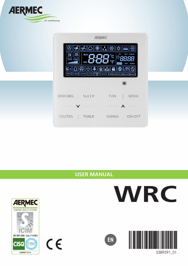
USER MANUAL WRC
40
EN 5389591_01 USER MANUAL WRC
Transcript of USER MANUAL WRC
EN
5389591_01
USER MANUAL
WRC


Contents
Wired panel - MVA unit ................................................................................................................... 1
User interface (display) .................................................................................................................. 1
User interface (buttons) ................................................................................................................. 4
Dimensions of the wired panel: ................................................................................................... 5
Serial connection: ......................................................................................................................... 5
Installing the wired panel .............................................................................................................. 5
Examples of serial connection between wired panel and indoor unit: .................................... 6
Functions available from wired panel .......................................................................................... 9
Switching the indoor unit ON and OFF: ................................................................................................................ 9 Modifying the operating mode for the indoor unit: .............................................................................................. 10 Modifying the operating temperature: ................................................................................................................ 11 Modifying fan speed: .......................................................................................................................................... 11 Modifying the programmed ON/OFF timer (COUNTDOWN mode): ................................................................... 12 Set system time (only used in CLOCK mode): ................................................................................................... 13 Modifying the programmed ON/OFF timer (CLOCK mode): .............................................................................. 14 Set delivery fin SWING: ....................................................................................................................................... 16 Set QUIET function (reduces the noise generated by the indoor unit): .............................................................. 17 Set Night-Time Comfort function: ........................................................................................................................ 18 Set the DISPLAY function on the indoor unit (led and two-figure display): ......................................................... 19 Set the ENERGY SAVING function (active on indoor unit): ................................................................................. 20 Set indoor unit FILTER CLEANING alarm: .......................................................................................................... 21 Set the X-FAN function on indoor unit: ................................................................................................................ 22 Set the ANTIFREEZE function on indoor unit: ..................................................................................................... 23 Set key lock on wired panel: ............................................................................................................................... 24 Display indoor unit OPERATING PARAMETERS: ................................................................................................ 25 List of operating parameters (read-only data): ................................................................................................... 26 Activation of indoor unit OPERATING PARAMETER modification menu: ............................................................ 28
Display operating errors or system messages: ......................................................................... 31
4
Wired panel - MVA unit
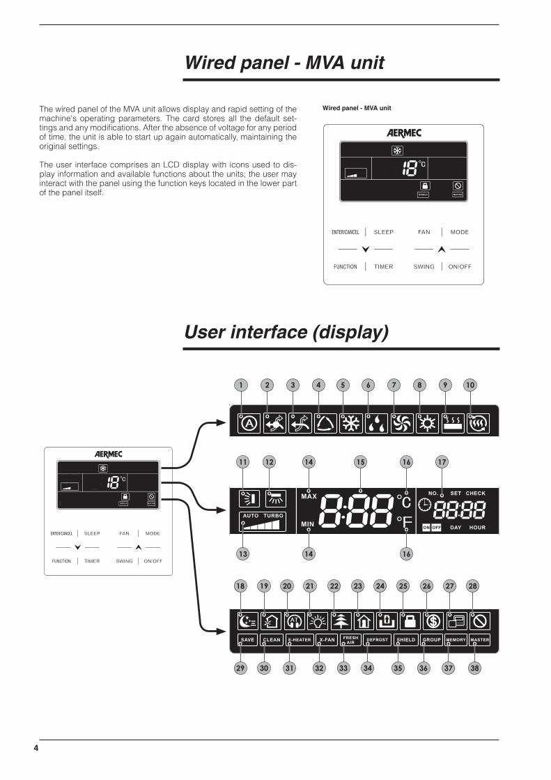
The wired panel of the MVA unit allows display and rapid setting of the machine's operating parameters. The card stores all the default set-tings and any modifications. After the absence of voltage for any period of time, the unit is able to start up again automatically, maintaining the original settings.
The user interface comprises an LCD display with icons used to dis-play information and available functions about the units; the user may interact with the panel using the function keys located in the lower part of the panel itself.
Wired panel - MVA unit
User interface (display)
1 2 3 4 5 6 7 8 9 10
11 12
13
14
14
15 16
16
17
18
29
19
30
20
31
21
32
22
33
23
34
24
35
25
36
26
37
27 28
38
5
Alarm Function Function available on models
1 Function not available ---
2 Function not available ---
3 Function not available ---
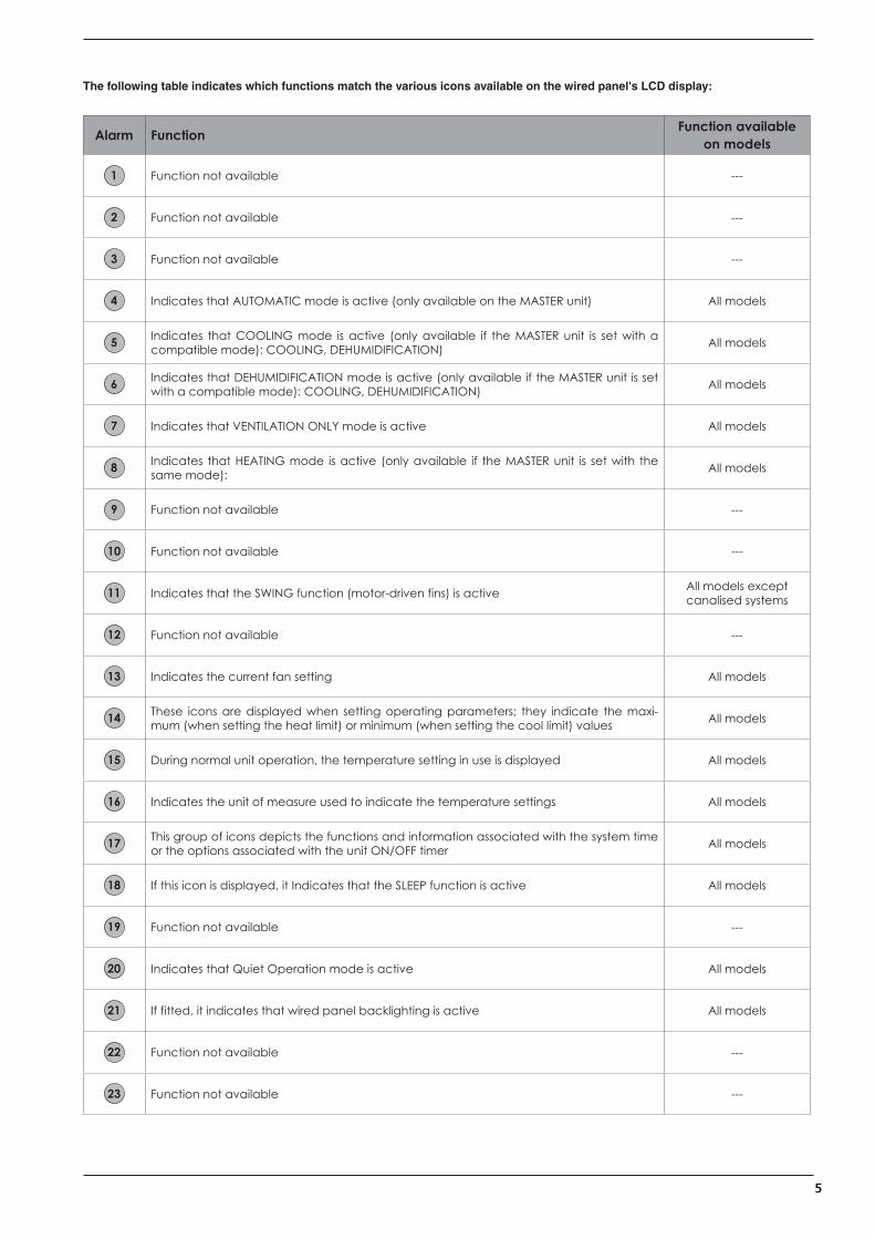
4 Indicates that AUTOMATIC mode is active (only available on the MASTER unit) All models
5 Indicates that COOLING mode is active (only available if the MASTER unit is set with a compatible mode): COOLING, DEHUMIDIFICATION) All models
6 Indicates that DEHUMIDIFICATION mode is active (only available if the MASTER unit is set with a compatible mode): COOLING, DEHUMIDIFICATION) All models
7 Indicates that VENTILATION ONLY mode is active All models
8 Indicates that HEATING mode is active (only available if the MASTER unit is set with the same mode): All models
9 Function not available ---
10 Function not available ---
11 Indicates that the SWING function (motor-driven fins) is active All models except canalised systems
12 Function not available ---
13 Indicates the current fan setting All models
14 These icons are displayed when setting operating parameters; they indicate the maxi-mum (when setting the heat limit) or minimum (when setting the cool limit) values All models
15 During normal unit operation, the temperature setting in use is displayed All models
16 Indicates the unit of measure used to indicate the temperature settings All models
17 This group of icons depicts the functions and information associated with the system time or the options associated with the unit ON/OFF timer All models
18 If this icon is displayed, it Indicates that the SLEEP function is active All models
19 Function not available ---
20 Indicates that Quiet Operation mode is active All models
21 If fitted, it indicates that wired panel backlighting is active All models
22 Function not available ---
23 Function not available ---
The following table indicates which functions match the various icons available on the wired panel's LCD display:

6
24 Function not available ---
25 Indicates that the key lock function is active on the panel All
26 Indicates that energy saving mode is active on the indoor unit connected All
27 Indicates that the wired panel is a slave (i.e. two wired panels are connected to the indoor unit: one master and one slave) All
28 Indicates that an attempt has been made to use a locked panel using monitoring soft-ware (MVA MONITORING) All
29 Indicates that the outdoor unit is operating in “safe” mode All
30 This icon appears in order to indicate that the filter on the indoor unit must be cleaned All
31 Function not available ---
32 Indicates that the X-Fan function is active on the unit (this functions dries the coil in cool or dehumidification mode) All
33 Function not available ---
34 Indicates that the outdoor unit is currently defrosting All
35 This icon indicates that the panel was disenabled by a remote controller (zone control, mains control or MVA MONITORING software) All
36 This icon indicates that the wired panel controls several indoor units (a group) All
37 Indicates that the Indoor unit is resuming the settings stored in memory (this event occurs after a black-out) All
38 Indicates that the indoor unit connected to the panel is the system MASTER All

7
User interface (buttons)
Alarm Function
1 Selects or Cancels desired function
2 Sets night-time comfort mode
3 Activates or de-activates certain extra functions
4 Sets data for unit timers
5 This button is used to decrease the selected data or pass to the previous data
6 Sets fan speed:
7 Sets the operating mode for the unit:
8 Sets automatic delivery fin oscillation (on units where this is envisaged)
9 Switches indoor unit ON/OFF
10 This button is used to increase the selected data or pass to the next data
1 25
3 4
6 710
8 9

8
Serial connection: The wired panel communicates with the Indoor unit through a serial port; it is possible to select several Indoor unit management configurations using the wired panel:
SINGLE connection, where the unit (or group of units) is managed by a single wired panel:A DUAL connection, where the unit (or group of units)
is managed by two wired panels, one of which is the MASTER and the other is the SLAVE:
B
Outdoor unit
Indoor unit
Wired panel
Outdoor unit
Indoor unit
Wired panel(MASTER)
Wired panel(SLAVE)
Installing the wired panel
112 22 35,5 42,5 34
112
8316
13
3 5
5
R2,7 R2,7
R2,7
R3,3
[mm]
WARNING: MVA SYSTEMS MUST HAVE A MASTER ONLY ONE) FOR CORRECT MANAGEMENT OF THE OPERATING MODES.FOR THE SETTING PROCEDURE, REFER TO THE SPECIFIC SECTION.
Dimensions of the wired panel:

9
Outdoor unit
Indoor unit (A) Indoor unit (B) Indoor unit (n)
Wired panel (A) Wired panel (B) Wired panel (n)
1
3
2
5
4 6
WARNING
2 , 4 , 6 ≤ 250m
Outdoor unit
Indoor unit (A) Indoor unit (B) Indoor unit (n)
Wired panel
1
3
2
5
4 6
WARNING
2 + 4 + 6 ≤ 250m
The first serial connection possibility envisages a panel (re-minder: each individual unit of group of units can be man-aged by a single panel or by two panels connected to the same Indoor unit in MASTER/SLAVE mode, as indicated in the
previous page) for each unit; this solution allows customised settings for the timer, setpoint and ventilation speed for each Indoor unit;
Examples of serial connection between wired panel and indoor unit:
The second serial connection possibility envisages only one panel (reminder: each individual unit of group of units can be managed by a single panel or by two panels connected to the same Indoor unit in MASTER/SLAVE mode, as indicated in
the previous page) for the overall group of units (a group may comprise max. 16 units); this solution allows unique settings for the timer, setpoint and ventilation speed for all the Indoor units in the group;

10
The first operation needed to install the wired panel is to open it using a flat screwdriver by pressing in the specific slot on the base of the panel.
After opening the wired panel, separate the front part from the rear body.
Mount the body securely on the wall (in the position spe-cifically chosen during the plant design stage) using the screws supplied with the equipment; before securing the panel, remember to pass the communication ca-ble (not supplied) through the rear hole in the body as shown in the figure.
NB The features of the communication cable are given in the following table.
Type of cable Max length Diameter NotesStandard 2-pole cable with
PVC sheath (60227 IEC 52 / 60227 IEC 53)
250 metres from 2x0.75 to 2x1.25mm2 Serial communication cable NOT supplied with the equipment
Connect the serial cable terminals (stripped as required) to the screw terminals on the panel board; after tightening appropriately, secure the cable using the cable clip as shown in the figure.
1 2
3 4
Wired panel installation procedure:

11
After connecting the serial cable, close the panel again by aligning the upper and lower bodies and pressing until the upper body hooks up with the lower body.
5
Notes for installing the wired panel It is advised not to install the wired panel where it may come into contact with water or direct sunlight; it is also advised to avoid installation too close to sources of intense heat.
WARNING: MVA SYSTEMS MUST HAVE A MASTER ONLY ONE) FOR CORRECT MANAGE-MENT OF THE OPERATING MODES.FOR THE SETTING PROCEDURE, REFER TO THE SPECIFIC SECTION.

12
Functions available from wired panel
Switching the indoor unit ON and OFF:
Indoor unit ON Indoor unit OFF
The Indoor unit (or group of indoor units) managed by the wired panel is/are turned on and off using the ON/Off button; every time it is pressed thereafter will switch the connect Indoor unit ON or OFF.

13
Modifying the operating mode for the indoor unit:The operating mode of the Indoor unit (or group of indoor units) managed by the wired panel can be modified using the MODE button; every time it is pressed thereafter will switch between one mode and the next (following the sequence indicated below); available modes are:
Auto ( ): This function automatically selects the most suitable operating mode based on the indoor temperature; this function does not allow any modifications to the setpoint (depending on the mode, default values will be chosen for hot and cold settings, having respective values of 20°C and 26°C) while ventilation and functions such as “swing” (if available from the Indoor unit model) are set as usual; while using this function, the icon for the selected mode will be displayed (hot or cold) as will as the Auto mode icon.
Cooling ( ): This mode allows room air to be conditioned until the temperature chosen as the operating setpoint is reached; this temperature may be between 16°C and 30°C;
Dehumidification ( ): This mode, in a similar way to the cooling mode, allows room air to be dehumidified: the operating temperature may be between 16°C and 30°C;
Ventilation Only ( ): This mode does not allow any modifications to the setpoint, and does not cool or heat the room air; however, it allows ventilation to be set as usual as well as the swing function (if available on the Indoor unit model);
Heating ( ): This mode allows room air to be heated until the temperature chosen as the operating setpoint is reached; this temperature may be between 16°C and 30°C;
Auto
Cooling
Dehumidification
Ventilation Only
Heating
Operating logic for AUTO Mode ( ):
(A) (B)(C)
Indoor temperature (TEMP)
22°C 26°C
If TEMP ≤ 22°C, Heat Mode will be activated with a setpoint of 20°C (setpoint can be chosen from parameter P38)
If 22°C < TEMP < 26°C, the last active mode will be activated (but if this is the initial start-up, then Ventilation Only mode will be selected)
If TEMP ≤ 26°C, Cool Mode will be activated with a setpoint of 26°C (setpoint can be chosen from parameter P37)
WARNING: AUTO mode is ONLY available on the Indoor unit set as MASTER.
14
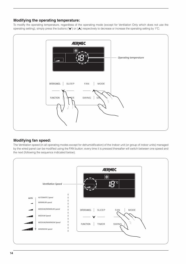
Modifying the operating temperature:To modify the operating temperature, regardless of the operating mode (except for Ventilation Only which does not use the operating setting), simply press the buttons ( ) or ( ) respectively to decrease or increase the operating setting by 1°C;
Operating temperature
Modifying fan speed:The Ventilation speed (in all operating modes except for dehumidification) of the Indoor unit (or group of indoor units) managed by the wired panel can be modified using the FAN button; every time it is pressed thereafter will switch between one speed and the next (following the sequence indicated below);
Ventilation Speed
AUTO AUTOMATIC Speed
MINIMUM speed
MEDIUM/MINIMUM speed
MEDIUM Speed
MEDIUM/MAXIMUM Speed
MAXIMUM speed

15
WARNING: the system envisages two types of timer management:• COUNTDOWN mode this mode manages programmed unit on-off operations by specifying an “interval” (in hours) after which the unit will switch on or off;• CLOCK mode: this mode manages programmed unit on-off operations by specifying a time when the operations will be per-formed (in this case, the system clock is activated and displayed);To set the required management mode, use parameter P33 in the Parameters Menu (for more information, see paragraph “operating parameters”); the default is: “COUNT DOWN”.
Modifying the programmed ON/OFF timer (COUNTDOWN mode):To set programmed ON or OFF operations using the countdown mode, perform the following operations:
(1) Press the “TIMER” button (if the Indoor unit is ON, the procedure will set a countdown to switch the unit OFF, otherwise the operations will set a time after which the unit will be switched ON); at this stage, the number of hours is shown after which the ON or OFF operation will be performed (next to this number, the wording “HOUR” will begin to flash);(2) press the ( ) or ( ) buttons, respectively to decrease or increase the counter by 0.5 hours;(3) press the “TIMER” button again to save the settings; the wording “HOUR” will become steady;
WARNING: after saving data, pressing the “TIMER” button again will cancel the previous setting.
the icon begins to flash
the icon becomes steady
(1) (2)
(3)
WARNING: once the unit is switched ON using a timer function, it will resume the functions and settings in use before the system was switched off for the last time.

16
Set system time (only used in CLOCK mode):To set the time on the system clock (only used if CLOCK mode is selected in the operating parameters, parameter P33), perform the following operations:
(1) Press and hold down the “TIMER” button (5 seconds); at this stage, the symbol ( ) appears will flash to indicate that system time modification mode has been selected;(2) press the ( ) or ( ) buttons, respectively to decrease or increase the clock by 1 minute;(3) press the “TIMER” button again or the “ENTER/CANCEL” button to save the time and exit the procedure;
the icon begins to flash
(1) (2)
(3)
x 5 seconds

17
Modifying the programmed ON/OFF timer (CLOCK mode):Clock mode is used to manage several functions:(a) time band management: this function is used to set a switch ON time and a subsequent switch OFF times, thereby defin-ing a time band within which the Indoor unit will operate;(b) only programmed switch ON: this function is used to set a switch ON time for the unit;(c) only programmed switch OFF: this function is used to set a switch OFF time for the unit;
To set clock mode functions, perform the following operations:
(1) With the unit ON, press the “TIMER” button; at this stage, the working “ON” appears and flashes to indicate the time when the switch ON operation should be performed;(2) press the ( ) or ( ) buttons, respectively to decrease or increase the switch on time by 0,5 hours; (3) press the “TIMER” button to save the switch ON time, the wording “ON” remains steady, while the wording “OFF” appears and flashes (to indicate that the switch OFF time must be entered);(4) press the ( ) or ( ) buttons, respectively to decrease or increase the switch off time by 0,5 hours;(5) press the “ENTER/CANCEL” button to save the time band settings and exit modify mode;
WARNING: after completing the entry of a time band, pressing the “TIMER” button again will activate cancel mode; whenever the “TIMER” button is pressed, the system passes from “ON” time to “OFF” time (the time currently selected will flash); after selecting the time to be cancelled, pressing the “ENTER/CANCEL” button will eliminate it.
this icon indicates that CLOCK mode is active
To set the various functions described at the beginning of this paragraph identified as (a), (b) and (c), the sequence of operations may be different; there follow the complete sequences for every function:(a) time band management: (1) + (2) + (3) + (4) + (5);(b) only programmed switch ON: (1) + (2) + (5);(c) only programmed switch OFF: (1) + (3) + (4) + (5);
(1)

18
(2) (3)
(4) (5)
WARNING: once the unit is switched ON using a timer function, it will resume the functions and settings in use before the system was switched off for the last time.

19
Set delivery fin SWING:To set delivery fin swing (function NOT AVAILABLE on canalised models), simply press the “SWING” button; every time it is pressed thereafter will switch between one function status to another (following the sequence indicated below);
SWING mode icon
Continuous SWING mode
SWING dis-enabled
SWING locked mode(position 1)
SWING locked mode(position 2)
SWING locked mode(position 3)
SWING locked mode(position 4)
SWING locked mode(position 5)

20
Set QUIET function (reduces the noise generated by the indoor unit):The system envisages two different types of operation: “QUIET” and “AUTO QUIET”, which differ in terms of the logic they use to manage fan speed. To set this function, perform the following operations:
(1) Press the “FUNCTION” button until one of the “QUIET” function icons is displayed ( ); this function directly sets fan speed to minimum, thereby ensuring the least noise possible; or “AUTO QUIET“ ( ); this function manages fan speed in relation to the difference between indoor temperature and the operating setting, in accordance with the following Cooling conditions:
• If the indoor air Temperature is higher than the setting temperature + 2°C, MEDIUM speed will be set;• If the indoor air Temperature is lower or equal to the setting temperature + 2°C, MINIMUM speed will be set;Or Heating conditions:• If the indoor air Temperature is lower than the setting temperature -2°C, MEDIUM speed will be set;• If the indoor air Temperature is higher than the setting temperature -2°C, MINIMUM speed will be set;
at this stage, the selected icon will begin to flash, indicating that the chosen low noise function mode selected is active;(2) press buttons ( ) or ( ) respectively to switch from “QUIET” to “AUTO QUIET” function;(3) press the “ENTER/CANCEL” button again to activate the selected function;
(1) (2)
(3)
WARNING: to disactivate this function, press the “FUNCTION” button until the function to be cancelled is selected and then press the “ENTER/CANCEL“ button
21
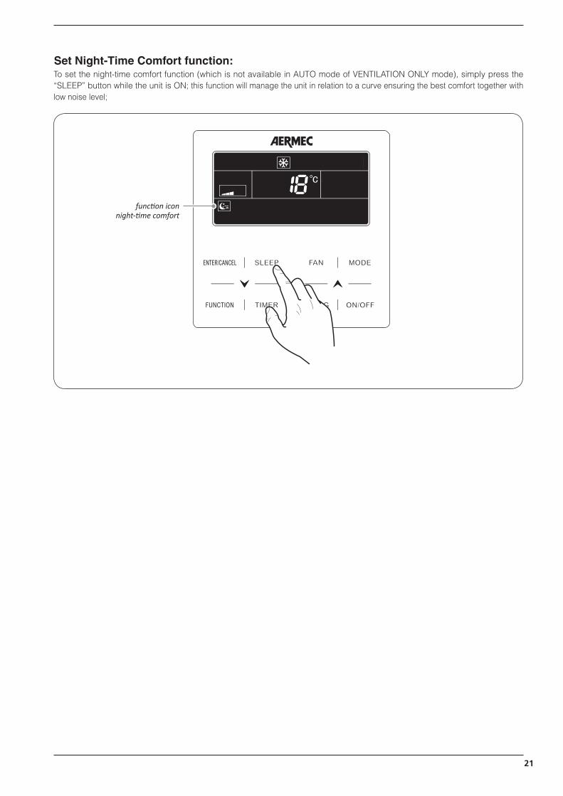
Set Night-Time Comfort function:To set the night-time comfort function (which is not available in AUTO mode of VENTILATION ONLY mode), simply press the “SLEEP” button while the unit is ON; this function will manage the unit in relation to a curve ensuring the best comfort together with low noise level;
function icon night-time comfort

22
Set the DISPLAY function on the indoor unit (led and two-figure display):To activate or de-activate illumination of the indoor unit display (obviously except for canalised units), perform the following operations:
(1) Press the “FUNCTION” key until the icon for this function appears ( ); at this stage, the selected icon will begin to flash, thereby indicating that the function has been selected;(2) press the “ENTER/CANCEL” button again to activate the selected function;
(1) (2)
WARNING: to disactivate this function, press the “FUNCTION” button until the function to be cancelled is selected and then press the “ENTER/CANCEL“ button
23
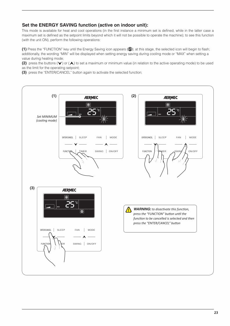
Set the ENERGY SAVING function (active on indoor unit):This mode is available for heat and cool operations (in the first instance a minimum set is defined, while in the latter case a maximum set is defined as the setpoint limits beyond which it will not be possible to operate the machine); to see this function (with the unit ON), perform the following operations:
(1) Press the “FUNCTION” key until the Energy Saving icon appears ( ); at this stage, the selected icon will begin to flash; additionally, the wording “MIN” will be displayed when setting energy saving during cooling mode or “MAX” when setting a value during heating mode;(2) press the buttons ( ) or ( ) to set a maximum or minimum value (in relation to the active operating mode) to be used as the limit for the operating setpoint;(3) press the “ENTER/CANCEL” button again to activate the selected function;
(1) (2)
(3)
WARNING: to disactivate this function, press the “FUNCTION” button until the function to be cancelled is selected and then press the “ENTER/CANCEL“ button
Set MINIMUM (cooling mode)
24
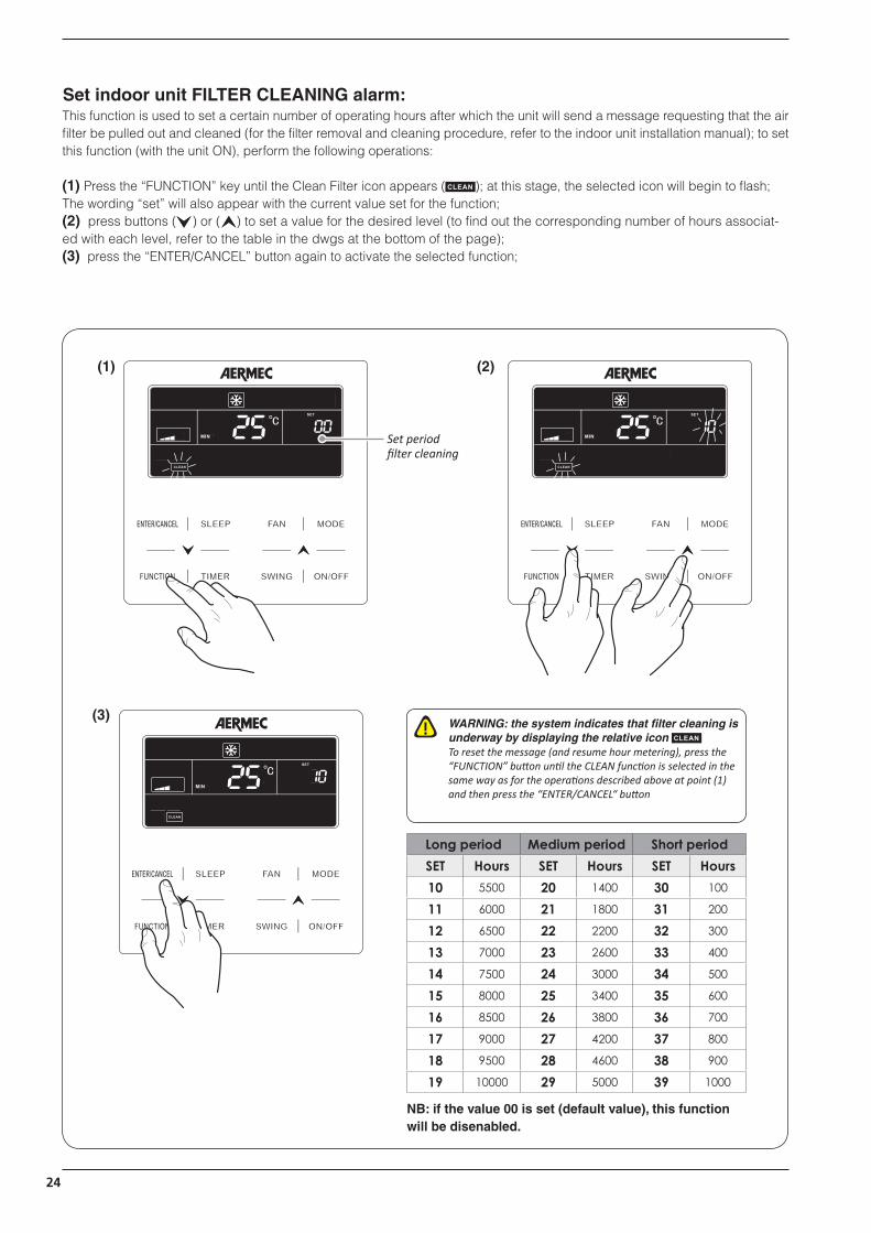
Set indoor unit FILTER CLEANING alarm:This function is used to set a certain number of operating hours after which the unit will send a message requesting that the air filter be pulled out and cleaned (for the filter removal and cleaning procedure, refer to the indoor unit installation manual); to set this function (with the unit ON), perform the following operations:
(1) Press the “FUNCTION” key until the Clean Filter icon appears ( ); at this stage, the selected icon will begin to flash; The wording “set” will also appear with the current value set for the function;(2) press buttons ( ) or ( ) to set a value for the desired level (to find out the corresponding number of hours associat-ed with each level, refer to the table in the dwgs at the bottom of the page);(3) press the “ENTER/CANCEL” button again to activate the selected function;
(1) (2)
(3)WARNING: the system indicates that filter cleaning is underway by displaying the relative icon To reset the message (and resume hour metering), press the “FUNCTION” button until the CLEAN function is selected in the same way as for the operations described above at point (1) and then press the “ENTER/CANCEL“ button
Set period filter cleaning
Long period Medium period Short periodSET Hours SET Hours SET Hours10 5500 20 1400 30 100
11 6000 21 1800 31 200
12 6500 22 2200 32 300
13 7000 23 2600 33 400
14 7500 24 3000 34 500
15 8000 25 3400 35 600
16 8500 26 3800 36 700
17 9000 27 4200 37 800
18 9500 28 4600 38 900
19 10000 29 5000 39 1000
NB: if the value 00 is set (default value), this function will be disenabled.

25
Set the X-FAN function on indoor unit:This function is used to dry the coil (only during cool and dehumidification modes) if the unit is switched off before reaching the desired setpoint, in order to avoid the formation of mould or bacteria on the coil; to activate or de-activate this function, perform the following operations:
(1) Press the “FUNCTION” key until the icon for this function appears ( ); at this stage, the selected icon will begin to flash, thereby indicating that the function has been selected;(2) press the “ENTER/CANCEL” button again to activate the selected function;
(1) (2)
WARNING: to disactivate this function, press the “FUNCTION” button until the function to be cancelled is selected and then press the “ENTER/CANCEL“ button

26
Set the ANTIFREEZE function on indoor unit:This function (only in Heat mode) allows setting a minimum room temperature; after setting it, the function is activated automat-ically if the room temperature falls below 6°C and is then deactivated when the temperature rises above 10°C; to activate or de-activate this function, perform the following operations:
(1) Press the “FUNCTION” key until the icon for this function appears ( ); at this stage, the selected icon will begin to flash, thereby indicating that the function has been selected;(2) press the “ENTER/CANCEL” button again to activate the selected function;
(1) (2)
WARNING: to disactivate this function, press the “FUNCTION” button until the function to be cancelled is selected and then press the “ENTER/CANCEL“ button

27
Set key LOCK on wired panel:This function is used to lock the buttons of the wired panel connected to the unit; to activate or de-activate this function, perform the following operations:
(1) press buttons ( ) and ( ) simultaneously for at least 5 seconds. The icon ( ) then appears to indicate button lock activation; on pressing these two buttons again (for a further 5 seconds), the unit is unlocked and the icon ( ) disappears;
(1)

28
Display indoor unit OPERATING PARAMETERS:This function is used to display a series of operating parameters (each code is associated with the letter “C”); the parameters in this menu may not be modified but only displayed (read only); to read the operating parameters, perform the following op-erations:
(1) press the “FUNCTION” button for at least 5 seconds, after which the temperature setting will be replaced by an indica-tion of the operating parameter currently displayed (from C00 up to C20; for more information about the operating parame-ters sequence and the data displayed, refer to the table provided below);(2) press the buttons ( ) or ( ) to scroll the operating parameters;(3) press the “ENTER/CANCEL” button again to exit the operating parameter display;
(1) (2)
(3)
Value of parameter
Parameter index
WARNING: the list of operating parameters complete with indexes and an explanation of the values is provided below!

29
String parameter Function Description of operating parameter
Indoor unit project number
This parameter indicates the project number assigned to the Indoor unit to which the wired panel is connected (if the panel is connected to several units, the lesser project number will be displayed). The project number is a value assigned automatically by the system so that each indoor unit can be specifically identified (auto-addressing function); this number is fundamental for identifying the unit through software in order to monitor the system (for more information as regards system monitoring software, refer to www.aermec.com)
System error monitor
This parameter is used to scroll all the project numbers (and consequently all the units in the system) to search for any errors; to scroll the list of units, perform the following operations:(1) Select the operating parameter “C01”;(2) Press the “MODE” button to enter the list of indoor units (after entering this list, the setpoint area will display any alarm codes while the timer zone will display the project number for the indoor unit in question; if the Indoor unit currently displayed is the system master, the ”MASTER” icon will be displayed);(3) Press the arrow buttons to scroll the indoor units;(4) Press the “ENTER/CANCEL” button to return to the list of operating parameters
WARNING: if an error occurs in one or more indoor units when assigning the project number, in place of this number (in the timer zone) error code C5 will be displayed; in this case, the system initialisation procedure must be repeated (for more information as regards system initialising, contact the area technical assistance service)
Total number of indoor units in the system
This parameter indicates (in the timer zone) the total number of indoor units connected to the system
Display the operating priority of these indoor
units
This parameter displays the priority assigned to each Indoor unit; priority means which units are used in case the system detects power drops, thereby making it possible to select which indoor units should be given priority, as required, over other units (in this parameter, this priority has a value of 01 while the standard priority has a value of 00); to scroll the priorities assigned to each unit, perform the following operations:(1) Select the operating parameter “C06”;(2) Press the “MODE” button to enter the list of indoor units (after entering this list, the setpoint area will display the project number for the indoor unit in question while the timer zone will display the priority setting; if the Indoor unit currently displayed is the system master, the ”MASTER” icon will be displayed);(3) Press the arrow buttons to scroll the indoor units;(4) Press the “ENTER/CANCEL” button to return to the list of operating parameters
Display the room temperature.
This parameter is used to display the room temperature read on each indoor unit (in accordance with the specific settings of each individual unit); to display the room temperatures, perform the following operations:(1) Select the operating parameter “C07”;(2) Press the “MODE” button to enter the list of indoor units (after entering this list, the setpoint area will display the project number for the indoor unit in question while the timer zone will display the room temperature for the indoor unit in question); if the Indoor unit currently displayed is the system master, the ”MASTER” icon will be displayed);(3) Press the arrow buttons to scroll the indoor units;(4) Press the “ENTER/CANCEL” button to return to the list of operating parameters
Display the current setting for the filter
cleaning alarm
This parameter indicates (in the timer zone) the number of days set as the period after which a message will be displayed requesting removal and cleaning of the air filter on the Indoor unit to which the wired panel is connected
Display the address of the wired panel
This parameter indicates (in the timer zone) the address assigned to the wired panel (this address is fundamental if two different wired panels are used to manage one or more units, since the two panels must have different addresses)
List of operating parameters (read-only data):

30
Number of units in the group
This parameter indicates (in the timer zone) the number of units in any group connected to the wired panel
Display external temper-ature; This parameter indicates (in the timer zone) the temperature of the external air
Display all project numbers at the
same time
This parameter is used to scroll all project numbers (and consequently all the units in the system) associated with the unit number (in relation to the total number of internal units in the system); to scroll the list of units, perform the following operations:(1) Select the operating parameter “C18”;(2) Press the “MODE” button to enter the list of indoor units (after entering this list, the setpoint area will display the number of the unit while the timer zone will display the project number for the indoor unit in question); if the Indoor unit currently displayed is the system master, the ”MASTER” icon will be displayed);(3) Press the arrow buttons to scroll the indoor units;(4) Press the “ENTER/CANCEL” button to return to the list of operating parameters
WARNING: • after displaying parameter C18, all indoor unit wired panels will display (in the timer zone) their specific project numbers, which will remain displayed until this function is closed; • reminder: it will not be possible to enter this parameter if access is attempted from a slave wired panel (installation with two wired panels connected to the same indoor unit);• reminder: pressing the “ON/OFF” button on any wired panel during this function will immediately finish it;• if, when displaying parameter C18, no operation is performed for more than 20 seconds, the function is automatically exited
Reserved parameter
TIMER zone
SETPOINT zone
31
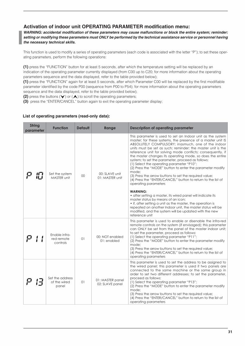
Activation of indoor unit OPERATING PARAMETER modification menu:WARNING: accidental modification of these parameters may cause malfunctions or block the entire system; reminder: setting or modifying these parameters must ONLY be performed by the technical assistance service or personnel having the necessary technical skills.
This function is used to modify a series of operating parameters (each code is associated with the letter “P”); to set these oper-ating parameters, perform the following operations:
(1) press the “FUNCTION” button for at least 5 seconds, after which the temperature setting will be replaced by an indication of the operating parameter currently displayed (from C00 up to C20; for more information about the operating parameters sequence and the data displayed, refer to the table provided below);(1) press the “FUNCTION” again for at least 5 seconds, after which Parameter C00 will be replaced by the first modifiable parameter identified by the code P00 (sequence from P00 to P54); for more information about the operating parameters sequence and the data displayed, refer to the table provided below);(2) press the buttons ( ) or ( ) to scroll the operating parameters;(3) press the “ENTER/CANCEL” button again to exit the operating parameter display;
String parameter Function Default Range Description of operating parameter
Set the system MASTER unit 00 00: SLAVE unit
01: MASTER unit
This parameter is used to set an Indoor unit as the system master; for these systems, the presence of a master unit IS ABSOLUTELY COMPULSORY; inasmuch, one of the indoor units must be set as such; reminder: the master unit is the reference unit for solving mode conflicts; consequently, if the master changes its operating mode, so does the entire system; to set the parameter, proceed as follows:(1) Select the operating parameter “P10”;(2) Press the “MODE” button to enter the parameter modify mode;(3) Press the arrow buttons to set the required value;(4) Press the “ENTER/CANCEL” button to return to the list of operating parameters
WARNING: • after setting a master, its wired panel will indicate its master status by means of an icon;• if, after setting a unit as the master, the operation is repeated on another Indoor unit, the master status will be modified, and the system will be updated with the new reference unit
Enable infra-red remote
controls01 00: NOT enabled
01: enabled
This parameter is used to enable or disenable the infra-red remote controls on the system (if envisaged); this parameter can ONLY be set from the panel of the master indoor unit; to set the parameter, proceed as follows:(1) Select the operating parameter “P11”;(2) Press the “MODE” button to enter the parameter modify mode;(3) Press the arrow buttons to set the required value;(4) Press the “ENTER/CANCEL” button to return to the list of operating parameters
Set the address of the wired
panel01 01: MASTER panel
02: SLAVE panel
This parameter is used to set the address to be assigned to the wired panel; this parameter is used if two panels are connected to the same machine or the same group in order to set two different addresses; to set the parameter, proceed as follows:(1) Select the operating parameter “P13”;(2) Press the “MODE” button to enter the parameter modify mode;(3) Press the arrow buttons to set the required value;(4) Press the “ENTER/CANCEL” button to return to the list of operating parameters
List of operating parameters (read-only data):

32
Set the number of units in the
group01
00: test disenabled 01-16: group with ...
units
This parameter performs a test on the group (if a group has been created) in order to specify how many indoor units belong to it. This test checks whether the number set in the parameter matches the number of units detected by the system in the group; if this function is disenabled (value 00) and the wired panel manages a group, no alarms will be displayed for any malfunctions in this group; to set the parameter, proceed as follows:(1) Select the operating parameter “P14”;(2) Press the “MODE” button to enter the parameter modify mode;(3) Press the arrow buttons to set the required value;(4) Press the “ENTER/CANCEL” button to return to the list of operating parameters
Set unit of measure 00 00: °C
01: °F
This parameter specifies which unit of measure is used to display temperatures; to set the parameter, proceed as follows:(1) Select the operating parameter “P16”;(2) Press the “MODE” button to enter the parameter modify mode;(3) Press the arrow buttons to set the required value;(4) Press the “ENTER/CANCEL” button to return to the list of operating parameters
Parameter reserved 05 --- ---
Parameter not used --- --- ---
Set type of clock 00 00: countdown
01: clock
This parameter is used to select which type of clock must be activated on the system; possible modes are:• COUNTDOWN: management of timed actions after a cer-tain number of hours (for more information about this mode, refer to page 15 in this manual);• STANDARD CLOCK: management of timed operations using the system clock (this clock must be updated by the user. For more information in this regard, refer to page 16 in this manual);to set the parameter, proceed as follows:(1) Select the operating parameter “P33”;(2) Press the “MODE” button to enter the parameter modify mode;(3) Press the arrow buttons to set the required value;(4) Press the “ENTER/CANCEL” button to return to the list of operating parameters
Set repetition of time settings 00 00: repetition disenabled
01: repetition enabled
This parameter is used to set (only if parameter P33 is set with the value 01) the repetition of time settings; if the rep-etition function is disenabled, the time settings will be per-formed only once and they will have to be set again every day; to set the parameter, proceed as follows:(1) Select the operating parameter “P34”;(2) Press the “MODE” button to enter the parameter modify mode;(3) Press the arrow buttons to set the required value;(4) Press the “ENTER/CANCEL” button to return to the list of operating parameters
Cool set for AUTO mode
25°C(77°F)
17°C~30°C(63°F~86°F)
This parameter is used to define a cool setpoint used in AUTO mode (reminder: the auto mode is only available on the master unit); to set the parameter, proceed as follows:(1) Select the operating parameter “P37”;(2) Press the “MODE” button to enter the parameter modify mode;(3) Press the arrow buttons to set the required value;(4) Press the “ENTER/CANCEL” button to return to the list of operating parameters

33
Heat set for AUTO mode
20°C(68°F)
16°C~29°C(61°F~84°F)
This parameter is used to define a heat setpoint used in AUTO mode (reminder: the auto mode is only available on the master unit); to set the parameter, proceed as follows:(1) Select the operating parameter “P38”;(2) Press the “MODE” button to enter the parameter modify mode;(3) Press the arrow buttons to set the required value;(4) Press the “ENTER/CANCEL” button to return to the list of operating parameters
Set indoor unit priority 00 00: normal priority
01: high priority
This parameter is used to select the priority to be assigned to the Indoor unit connected to the wired panel; this priority, if the unit detects power drops, makes it possible to exclude indoor units having normal priority in favour of those with high priority; to set the parameter, proceed as follows:(1) Select the operating parameter “P43”;(2) Press the “MODE” button to enter the parameter modify mode;(3) Press the arrow buttons to set the required value;(4) Press the “ENTER/CANCEL” button to return to the list of operating parameters
Enable filter cleaning alarm 00
00: filter cleaning alarm disenabled01: filter cleaning alarm enabled
This parameter is used to enable or disenable the filter cleaning alarm (set using the specific function described in this manual on page 25); to set the parameter, proceed as follows:(1) Select the operating parameter “P46”;(2) Press the “MODE” button to enter the parameter modify mode;(3) Press the arrow buttons to set the required value;(4) Press the “ENTER/CANCEL” button to return to the list of operating parameters
Set delivery fin standard open-
ing01
01: 25° opening02: 30° opening03: 35° opening
This parameter is used to set the standard opening (i.e. the position taken by the delivery fin once the unit is switched on for heat or cool) of the indoor units fitted with motor-driven delivery fins (inasmuch, canalised units are excluded); to set the parameter, proceed as follows:(1) Select the operating parameter “P49”;(2) Press the “MODE” button to enter the parameter modify mode;(3) Press the arrow buttons to set the required value;(4) Press the “ENTER/CANCEL” button to return to the list of operating parameters
Parameter reserved 18°C --- ---
Parameter reserved 22°C --- ---
Parameter reserved 00 --- ---

34
Display operating errors or system messages:These units envisage signals for various alarms, operating errors or system messages using a code shown on the wired panel display (as well as on the indoor unit display for units where this is envisaged); alarm codes and related causes are listed below.
WARNING: reminder: in the event of an alarm, the unit must be switched off and the technical assistance service contacted for any kind of intervention on the unit.
current alarm code(if there are several simultaneous alarms, the codes will be displayed on rotation)
Code Type signal Description
Outdoor unit Outdoor unit error
Outdoor unit High pressure alarm
Outdoor unit Low temperature alarm (discharge)
Outdoor unit Low pressure alarm
Outdoor unit Excessive temperature on compressor discharge
Outdoor unit Temperature alarm on compressor discharge 1
Outdoor unit Temperature alarm on compressor discharge 2
Outdoor unit Temperature alarm on compressor discharge 3
Outdoor unit Temperature alarm on compressor discharge 4
Outdoor unit Temperature alarm on compressor discharge 5
Outdoor unit Temperature alarm on compressor discharge 6
Outdoor unit Outdoor unit electronic card malfunction
Outdoor unit High pressure sensor alarm
Outdoor unit Low pressure sensor alarm
Outdoor unit Temperature sensor error on compressor discharge 1
Outdoor unit Temperature sensor error on compressor discharge 2

35
Code Type signal Description
Outdoor unit Temperature sensor error on compressor discharge 3
Outdoor unit Temperature sensor error on compressor discharge 4
Outdoor unit Temperature sensor error on compressor discharge 5
Outdoor unit Temperature sensor error on compressor discharge 6
Outdoor unit Compressor power supply current sensor error 1
Outdoor unit Compressor power supply current sensor error 2
Outdoor unit Compressor power supply current sensor error 3
Outdoor unit Compressor power supply current sensor error 4
Outdoor unit Compressor power supply current sensor error 5
Outdoor unit Compressor power supply current sensor error 6
Outdoor unit Temperature sensor error on compressor 1
Outdoor unit Temperature sensor error on compressor 2
Outdoor unit Over-current protection on compressor 1
Outdoor unit Over-current protection on compressor 2
Outdoor unit Over-current protection on compressor 3
Outdoor unit Over-current protection on compressor 4
Outdoor unit Over-current protection on compressor 5
Outdoor unit Over-current protection on compressor 6
Outdoor unit 4 way valve protection
Outdoor unit High pressure protection
Outdoor unit Low pressure protection
Outdoor unit Abnormal pressure protection
Outdoor unit Flow switch alarm protection
Outdoor unit General pressure protection
Outdoor unit Ambient air temperature probe
Outdoor unit Temperature probe 1 error for defrosting
Outdoor unit Temperature probe 2 error for defrosting

36
Code Type signal Description
Outdoor unit Under-cooling probe error (fluid leak)
Outdoor unit Under-cooling probe error (gas leak)
Outdoor unit Error on fluid separator inlet probe
Outdoor unit Error on fluid separator outlet probe
Outdoor unit Humidity probe error
Outdoor unit Coil outlet probe error
Outdoor unit Oil return temperature probe error
Outdoor unit System clock error
Outdoor unit Thermic protection (1) compressor top plate
Outdoor unit Thermic protection (2) compressor top plate
Outdoor unit Inverter compressor control card error
Outdoor unit Inverter compressor control card malfunction
Outdoor unit Inverter compressor power supply module protection
Outdoor unit Inverter compressor re-start protection
Outdoor unit Fan control card error
Outdoor unit Fan control card malfunction
Outdoor unit Fan power supply module protection
Indoor unit Indoor unit error
Indoor unit Fan protection
Indoor unit Electric resistor protection
Indoor unit Condensate collection basin full
Indoor unit Wired panel power supply error
Indoor unit Anti-freeze protection
Indoor unit No master set on system
Indoor unit Insufficient power supply
Indoor unit Too many units in the group
Indoor unit Water temperature probe error

37
Code Type signal Description
Indoor unit Air quality alarm
Indoor unit Incompatibility between indoor and outdoor units
Indoor unit Indoor unit control electric card error
Indoor unit Room air sensor error
Indoor unit Error on temperature probe on coil inlet
Indoor unit Error on temperature probe on coil outlet
Indoor unit Humidity probe error
Indoor unit Water temperature probe error
Indoor unit Jumper cap position error
Indoor unit Indoor unit addressing error
Indoor unit Connection error between wired panel and Indoor unit control card
Indoor unit Dip switch setting error for selecting size
Indoor unit Room air probe error
Indoor unit Carbon dioxide probe error
Indoor unit Indicates that Debug mode is active
Status codes Unit on hold because of debug mode
Status codes Compressor operating parameter control procedure underway
Status codes Insufficient refrigerant gas quantity warning (replenishment required)
Status codes Defrosting cycle currently underway
Status codes Unit in test mode
Status codes Pump down mode currently underway
Status codes Indoor unit air filter cleaning warning
Status codes System emergency stop (from remote system)
Status codes System emergency stop
Status codes Protected operation
Debug codes Jumper cap setting error on outdoor unit (capacity selector)
Debug codes Protection on system power supply phase sequence

38
Code Type signal Description
Debug codes Refrigerant low protection
Debug codes Addressing error on compressor control card
Debug codes Electronic expansion valve abnormal function alarm
Debug codes Indoor unit refrigerant circuit malfunction
Debug codes Outdoor unit refrigerant circuit malfunction
Debug codes Master unit set successfully
Debug codes Insufficient gas added
Debug codes Emergency mode (wrong compressor dip switch settings)
Debug codes Communication error (general)
Debug codes Communication error (between master and compressor control card)
Debug codes Communication error (between master and fan control card)
Debug codes Refrigerant gas quantity error
Debug codes Automatic addressing procedure error
Debug codes Addressing setting error on outdoor unit
Debug codes Power yield error (excessive power)
Debug codes Power yield error (low power)
Debug codes Master error (more than one master has been assigned)
Debug codes General address assignment error
Debug codes Master error (more than one master has been assigned for wired panels)
Debug codes Communication error (between Indoor unit and remote receiver)
Debug codes IP address assignment error


AERMEC S.p.A.I-37040 Bevilacqua (VR) - ItalyVia Roma, 996 - Tel. (+39) 0442 633111Telefax (+39) 0442 93577 - (+39) 0442 93566www.aermec.com - [email protected]
I dati tecnici riportati nella presente documentazione non sono impegnativi.AERMEC S.p.A. si riserva la facoltà di apportare in qualsiasi momento tutte le modifiche ritenute nec-essarie per il miglioramento del prodotto.Les données mentionnées dans ce manuel ne constituent aucun engagement de notre part. Aermec S.p.A. se réserve le droit de modifier à tous
moments les données considérées nécessaires à l’amelioration du produit.The technical data in this document are not binding.Aermec S.p.A. shall have the right to introduce at any time whatever modifications deemed necessary to the improvement of the product.Im Sinne des technischen Fortsschrittes behält sich
Aermec S.p.A. vor, in der Produktion Änderungen und Verbesserungen ohne Ankündigung durchzuführen.Los datos técnicos indicados en la presente documentación no son vinculantes.Aermec S.p.A. se reserva el derecho de realizar en cualquier momento las modificaciones que estime necesarias para mejorar el producto.