User Manual for Defect Management in ... - Mahindra & Mahindramnmrvalm.mahindra.com/Rational/User...
29
1 User Manual for Defect Management in eLMS For AFS PD - E&E and Relevant users only Released on 30 th Jan 2016 Strictly Confidential document. All Rights Reserved to Mahindra & Mahindra also regarding distribution, exploitation, editing, and reproduction as well as in the event of application for Industrial Property Rights.
Transcript of User Manual for Defect Management in ... - Mahindra & Mahindramnmrvalm.mahindra.com/Rational/User...

1
User Manual for
Defect Management in eLMS
For AFS PD - E&E and Relevant users only
Released on 30th Jan 2016
Strictly Confidential document. All Rights Reserved to Mahindra & Mahindra also
regarding distribution, exploitation, editing, and reproduction as well as in the event of
application for Industrial Property Rights.

2
Document Release History
Revision Author Version Summary Approver
V1.0.0 Jawad Ahmed S Initial Version.
V1.0.1 Jawad Ahmed S Initial Version Review.
V1.0.2 Jawad Ahmed S Improvements made on end user feedbacks
V1.0.3 Sunil Kumar V Improvements made on end user feedbacks
such as modification on work flow, severity
rating criteria and necessary screenshot
changes.
V1.1.0 Sunil Kumar V Added newer version of defect work flow;
changes pertaining to new work flow
mirrored in the document content too.
V1.1.1 Jawad Ahmed S Updated the document based on the
workflow changes.
V2.0.0 Jawad Ahmed S Modified the document based on the new UI
V2.0.1 Jawad Ahmed S Modified the document based on the new
workflow
V3.0.0 Jawad Ahmed S Modified the document as per the new
workflow shared by Kishore & Selva

3
Table Of Content
1. INTRODUCTION ....................................................................................................... 4
2. DEFECT ENTRY PROCESS WORKFLOW. FIGURE 1: .................................................... 5
3. SEVERITY RATING CRITERIA ................................................................................... 6
4. ACCESS ELMS LOGIN PAGE THROUGH MCONNECT ................................................... 7
5. DEFECT CREATION ................................................................................................... 9
6. DEFECT STATES ...................................................................................................... 11
6.1. SUBMITTED ............................................................................................................................................................... 11
6.2. UNDER REVIEW ......................................................................................................................................................... 13
6.3. INFO REQUESTED ...................................................................................................................................................... 14
6.4. SE REJECTED .............................................................................................................................................................. 15
6.5. ANALYSIS ................................................................................................................................................................... 16
6.6. ACCEPTED .................................................................................................................................................................. 16
6.7. DEFECT AGREED ........................................................................................................................................................ 17
6.8. IMPLEMENTATION STARTED ..................................................................................................................................... 18
6.9. IMPLEMENTATION COMPLETED ............................................................................................................................... 18
6.10. VALIDATION STARTED ........................................................................................................................................... 19
6.11. CLOSED .................................................................................................................................................................. 19
6.12. UNDER DISCUSSION .............................................................................................................................................. 21
6.13. REJECTED ............................................................................................................................................................... 22
6.14. ESCALATED ............................................................................................................................................................ 23
6.15. DUPLICATE ............................................................................................................................................................ 24
7. ADDING A FILE TO THE DEFECT ............................................................................. 27
8. LINKING AN EXISTING LESSONS LEARNT .............................................................. 28

4
1. Introduction
The scope of this document is to instruct / teach an end user on how to log a defect using
eLMS tool.
This tool can be used as documentation and tracking system by management. Earlier it was
very difficult to track all the concerns in XL sheets.
The confidentiality will also be maintained through access control.
Following are the states present in the defect management system;
1.1 CREATED
1.2 SUBMITTED
1.3 UNDER REVIEW
1.4 INFO REQUESTED
1.5 SE REJECTED
1.6 ANALYSIS
1.7 ACCEPTED
1.8 DEFECT AGREED
1.9 IMPLEMENTATION STARTED
1.10 IMPLEMENTATION COMPLETED
1.11 VALIDATION STARTED
1.12 CLOSED
1.13 UNDER DISCUSSION
1.14 REJECTED
1.15 ESCALATED
1.16 DUPLICATE
The explanations to all these states are explained in details in Chapter 6.

5
2. Defect entry process Workflow. Figure 1:

6
3. Severity Rating Criteria
An end user can log defects based on the following criteria given below.
Effect Criteria: Severity of Effect Ranking
Failure to meet
safety and / or
regulatory
requirement
Potential failure mode affects safe vehicle operation and
/or involves noncompliance with government regulation
without warning
10
Potential failure mode affects safe vehicle operation and
/or involves noncompliance with government regulation
with warning
9
Loss or degradation
of Primary function
Loss of Primary function 8
(Vehicle inoperable, does not affect safe vehicle operation)
Degradation of Primary function 7
(Vehicle operable, but at reduced level of performance)
Loss or degradation
of secondary
function
Loss of secondary function
6 (Vehicle operable, but comfort / convenience functions
inoperable)
Degradation of secondary function
5 (Vehicle operable, but comfort / convenience functions at
reduced level of performance)
Annoyance
Appearance or Audible Noise, Vehicle operable, item does
not conform and noticed by most customers (>75%). 4
Appearance or Audible Noise, Vehicle operable, item does
not conform and noticed by more customers (50%). 3
Appearance or Audible Noise, Vehicle operable, item does
not conform and noticed by discriminating customers
(<25%).
2
No Effect No discernible effect 1
7
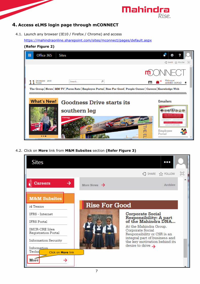
4. Access eLMS login page through mCONNECT
4.1. Launch any browser (IE10 / Firefox / Chrome) and access
https://mahindraonline.sharepoint.com/sites/mconnect/pages/default.aspx
(Refer Figure 2)
4.2. Click on More link from M&M Subsites section (Refer Figure 3)
Click on More link

8
4.3. Click on E&E eLMS link from the MConnect // M&M Subsites list (Refer Figure 4)
4.4. eLMS Login page is loaded successfully as shown below (Refer Figure 5)
Click on E&E eLMS link from
M&M Subsites

9
5. Defect creation
5.1. Defect creation is project specific. People within a Project only can create and view the
defects.
5.2. To create a defect you need to give your login ID (Mahindra\Token No) and the password
that is given for Windows login.
5.3. Once you login E&E eLMS Dashboard is displayed (Refer Figure 6)
Figure 6:
5.4. Select the project from Project area (in this case S101) and view the dashboard as shown
in Figure 7:
Click on Raise a Defect
icon to create a defect
10
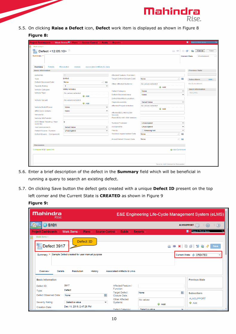
5.5. On clicking Raise a Defect icon, Defect work item is displayed as shown in Figure 8
Figure 8:
5.6. Enter a brief description of the defect in the Summary field which will be beneficial in
running a query to search an existing defect.
5.7. On clicking Save button the defect gets created with a unique Defect ID present on the top
left corner and the Current State is CREATED as shown in Figure 9
Figure 9:
Defect ID

11
6. Defect states
6.1. SUBMITTED
6.1.1. Initially defect can be created by any E&E stakeholder.
6.1.2. In this case the defect is created by Test Engineer. TE collects all the information,
expands the Current State field and selects the action Initiate TL Review.
6.1.3. All mandatory fields are displayed (Refer Figure 10)
Figure 10:
6.1.4. Fill all the mandatory fields in Overview tab, ‘ ’ buttons will help the creator to
pick multiple values by holding Ctrl key (Refer Figure 11).
Figure 11:
Select the action Initiate
TL Review if creator is TE
This Add button is
a Picker list where
multiple values can
be selected

12
6.1.4 Similarly fill all the mandatory fields in the Details tab, Quick Information section will
display the DC’s short id as subscriber and a mail notification will be send to subscribers
listed on Subscribers section on each state transitions. (Refer Figure 12)
Figure 12:
Note: DC can add any number of subscribers by clicking ‘Add’ and remove subscribers
by moving the cursor over subscribers name which enables the delete ‘ ’ button.
6.1.5 If TE select other options apart from Initiate TL Review and try to save, no
permission for this user will be displayed.
6.1.6 Additionally, DC creator can add suggestions/remarks/comments by clicking 'Add
Comment' icon under the 'Discussion' section, provide the TL name in the Assigned
To field and click Save.
6.1.7 The defect gets submitted to TL and the state changes to SUBMITTED. TL will get a
mail notification that a defect has been submitted and it is ready for review. (Refer
Figure 13)
Figure 13:

13
6.2. UNDER REVIEW
6.2.1. TL will review the defect and if it is valid then TL will select the action Initiate SE
Review, select SE name in Assigned To field and save the defect (Refer Figure 14)
Figure 14:
6.2.2. If the creator is a Test Lead then he can select the same action Initiate SE Review,
select SE name in Assigned To field and Save the defect (Refer Figure 14)
6.2.3. The state changes to UNDER REVIEW, SE will get a mail notification that a defect has
been submitted for review (Refer Figure 15)
Figure 15:
Select the action Initiate
SE Review by TL
Select the
reviewer name in
Assigned To
field

14
6.3. INFO REQUESTED
6.3.1. At the time of reviewing, SE can seek clarifications from DC by clicking Add Comment
icon and providing their comments under the 'Discussion' section
6.3.2. SE will select the action Seek Clarification and click save, an automated email is sent
to DC seeking for more clarifications on the defect (Refer Figure 16)
Figure 16:
6.3.3. The state changes to INFO REQUESTED as shown in Figure 17
Figure 17:
Select the action Seek
Clarification if SE
needs more info
Provide the details
required in this field

15
6.3.4. TL has to key in the required information, select the action Initiate SE Review (Refer
Figure 14) and click save. System Engineer will receive an email notification for further
review.
6.3.5. The state changes to UNDER REVIEW (Refer Figure 15)
6.3.6. SE will receive a mail notification that the defect has been updated with required
information.
6.4. SE REJECTED
6.4.1. SE can reject a defect if it is not valid. In that case SE will select the action SE Rejects,
provide the comments in Reason for Rejection field and save the defect. (Refer
Figure 18)
Figure 18:
6.4.2. The state changes to SE REJECTED, DC receives a mail notification (Refer Figure 19)
Figure 19:
Select the action SE
Rejects if SE is not
convinced with the defect
Provide the Reason
for Rejection in this
field

16
6.5. ANALYSIS
6.5.1. If DC is not convinced with SE’s decision, they can do a joint analysis with SE by
selecting the action Joint Analysis and save the defect (Refer Figure 20)
Figure 20:
6.5.2. The state changes to ANALYSIS (Refer Figure 21)
Figure 21:
6.5.3. SE, DC & subscribers (if any) will receive a mail notification on the defect status
6.5.4. DC and SE will perform a joint analysis on the defect
6.6. ACCEPTED
6.6.1. After joint analysis, if SE & DC confirms it as a defect then SE will select the action
Accept as a New Defect, select the Supplier’s name in the Assigned To field and
save the defect (Refer Figure 22)
Figure 22:
6.6.2. The state changes to ACCEPTED, Supplier gets a mail notification (Refer figure 23).
Select the action Joint
Analysis if creator is
not convinced with
SE’s decision
Select the action Accept as
a New Defect if SE is
convinced with creator after
joint analysis

17
Figure 23:
6.6.3. If the creator is a System Engineer (SE) then he/she can directly select the action SE
Accepts & Assign to Supplier, select the Supplier name in the Assigned To field and
save the defect (Refer Figure 24).
Figure 24:
6.6.4. The state changes to ACCEPTED, Supplier gets a mail notification (Refer Figure 23).
6.7. DEFECT AGREED
6.7.1 Supplier will start reviewing the defect and if he agrees then he will select the action
Supplier Agrees, select the SE name in the Assigned To field and save the defect
(Refer Figure 25)
Figure 25:
6.7.2 The state changes to DEFECT AGREED, SE will get the notification that the defect is
been agreed by supplier (Refer Figure 26).
Figure 26:
Creator will select the action
SE Assigns to Supplier if
he/she is a System Engineer
Supplier will select the action
Supplier Agrees if he
agrees the defect

18
6.8. IMPLEMENTATION STARTED
6.8.1. Supplier start working on the defect by selecting the action Started Implementation,
fill Root Cause Analysis (RCA) mandatory field and save the defect (Refer Figure 27).
Figure 27:
6.8.2. The state changes to IMPLEMENTATION STARTED (Refer Figure 28)
Figure 28:
6.9. IMPLEMENTATION COMPLETED
6.9.1. The supplier will fix the defect and once it is done he will assign the released version
back to SE by selecting the action Ready for M&M Testing, fill the Fixed ECU HW /
SW Version, Implementation Completed Date, Solution / Action taken to fix
the defect, SE name in the Assigned To fields, Link the defect to System
Release Version and save the defect (Refer Figure29).
Figure 29:
6.9.2. The state changes to IMPLEMENTATION COMPLETED, SE gets a mail notification
(Refer Figure 30).
Figure 30:
Supplier selects the action
Started Implementation
Supplier will fill all the
mandatory fields and select the
action Ready for M&M Testing
19
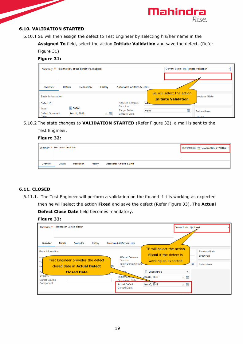
6.10. VALIDATION STARTED
6.10.1 SE will then assign the defect to Test Engineer by selecting his/her name in the
Assigned To field, select the action Initiate Validation and save the defect. (Refer
Figure 31)
Figure 31:
6.10.2 The state changes to VALIDATION STARTED (Refer Figure 32), a mail is sent to the
Test Engineer.
Figure 32:
6.11. CLOSED
6.11.1. The Test Engineer will perform a validation on the fix and if it is working as expected
then he will select the action Fixed and save the defect (Refer Figure 33). The Actual
Defect Close Date field becomes mandatory.
Figure 33:
SE will select the action
Initiate Validation
TE will select the action
Fixed if the defect is
working as expected Test Engineer provides the defect
closed date in Actual Defect
Closed Date

20
6.11.2. The state changes to CLOSED (Refer Figure 34)
Figure 34:
6.11.3. While validating if the defect is not working as expected then TE will select the action
Not Fixed, select the supplier name in the Assigned To field and save the defect.
(Refer Figure 35)
Figure 35:
6.11.4. The state changes to IMPLEMENTATION STARTED (Refer Figure 28)
6.11.5. The supplier will fix the defect and once it is done he will assign the released version
back to SE by selecting the action Ready for M&M Testing, fill the Fixed ECU HW /
SW Version, Implementation Completed Date, Solution / Action taken to fix
the defect, SE name in the Assigned To fields, Link the defect to System
Release Version and save the defect (Refer Figure29).
6.11.6. The state changes to IMPLEMENTATION COMPLETED, SE gets a mail notification
(Refer Figure 30).
6.11.7. SE will then assign the defect to Test Engineer by selecting his name in the Assigned
To field, select the action Initiate Validation and save the defect. (Refer Figure
31)
TE will select the action
Not Fixed if defect is not
working as expected
TE will select
supplier name in
the Assigned To
field

21
6.11.8. The state changes to VALIDATION STARTED (Refer Figure 32), a mail is sent to
the Test Engineer.
6.11.9. The Test Engineer will perform a validation on the fix and if it is working as expected
then he will select the action Fixed and save the defect (Refer Figure 33). The Due
Date field becomes mandatory which had to be updated by the TE.
6.11.10. The state changes to CLOSED (Refer Figure 34)
6.12. UNDER DISCUSSION
6.12.1. Supplier receives the defect in ACCEPTED state. He starts reviewing and if he feels
the defect is not valid then he will select the action Supplier Disagrees, provide the
reason in Reason for Rejection field, assign it back to SE and save the defect (Refer
Figure 36).
Figure 36:
6.12.2. The state changes to UNDER DISCUSSION (Refer Figure 37), a mail is sent to SE.
Figure 37:
6.12.3. If SE does not agree to the comments given by Supplier, then he/she will select the
action SE Disagrees Rejection, assign it back to Supplier and save the defect.
(Refer Figure 38)
Supplier will select
the action Supplier
Disagrees, assign
it back to SE
Supplier will provide
the reason in Reason
for Rejection field

22
6.12.4. The state changes to ACCEPTED (Refer Figure 23)
Figure 38:
6.12.5. The process initiates again as per the flow and the defect gets closed.
6.12.6. If SE agrees with supplier then he/she will select the action SE Agrees Rejection and
save the defect (Refer Figure 39).
Figure 39:
6.12.7. The state change to REJECTED and no further action can be performed.
6.13. REJECTED
6.13.1. Initially TE creates the defect and assigns it to TL for review (Refer Figure 10).
6.13.2. If TL confirms it is not a defect then he/she will select the action TL Rejects, fill the
Reason for Rejection mandatory field and save the defect (Refer Figure 40).
Figure 40:
TL will select the action TL
Rejects if he/she is not
convinced with the defect
Provide the Reason for
Rejection in this field
SE will select the action SE
Disagrees Rejection if SE
does not agree with Supplier
SE will select the action
SE Agrees Rejection if
SE agree with Supplier

23
6.13.3. The state changes to REJECTED and no further action can be performed (Refer Figure
41).
Figure 41:
6.13.4. When the defect is in UNDER REVIEW state (Refer Figure 15), SE will review and
confirm the defect is not valid then he/she will select the action SE Rejects, fill the
Reason for Rejection mandatory field and save the defect (Refer Figure 18)
6.13.5. The state changes to SE REJECTED (Refer Figure 19), creator will receive a mail
notification.
6.13.6. If creator accepts the rejection by SE, he will select the action Agrees Rejection and
save the defect (Refer Figure 42)
Figure 42:
6.13.7. The state changes to REJECTED (Refer Figure 41).
6.14. ESCALATED
6.14.1. When SE rejects the defect the state will be in SE REJECTED (Refer Figure 19).
6.14.2. If creator is not convinced with SE’s rejection, he can escalate the defect to System
Lead (SL) by selecting the action Escalate, select SL name in the Assigned To field
and save the defect. (Refer Figure 43)
Figure 43:
Select the action Agrees Rejection
if creator agrees SE’s decision
TE can escalate the defect to
SL on SE Rejection by
selecting the action Escalate

24
6.14.3. The state changes to ESCALATED (Refer Figure 44)
Figure 44:
6.14.4. The System Lead (SL), DC, SE and subscribers (if any) will receive a mail notification
of the defect status.
6.14.5. SL will go through the discussions and inputs of DC and SE.
6.14.6. If SL accepts the defect, then he will select the action Accept as a New Defect and
save the defect (Refer Figure 22)
6.14.7. The state changes to ACCEPTED (Refer Figure 23)
6.14.8. If SL rejects the defect, then he will select the action SL Rejects and save the defect
(Refer Figure 45)
Figure 45:
6.14.9. The state changes to REJECTED (Refer Figure 41).
6.15. DUPLICATE
6.15.1. In UNDER REVIEW state SE will perform a review on the defect and if he finds the
defect already exist then he will select the action Accept as a Duplicate, go to
Resolution tab (Refer Figure 46).
SL can reject the defect if not
convinced by selecting the
action SL Rejects

25
Figure 46:
6.15.2. Expand the drop down and select Set Duplicate Of option (Refer Figure 47)
Figure 47:
6.15.3. From the Select Work Item dialog select Defect from the Type drop down, enter
either the Summary or the Defect ID in the search phrase, the result is shown in the
Matching Work Items section (Refer Figure 48).
SE will select the action
Accept as a Duplicate if the
defect already exist
Expand Add
Related drop down
Select Set Duplicate Of

26
Figure 48:
6.15.4. Select the defect and click OK from the above dialog. The defect gets added as
Duplicate Of as shown in the Figure 49.
Figure 49:
6.15.5. On clicking save the state changes to DUPLICATE. In quick Information the Duplicate
Of defect details is displayed (Refer Figure 50)
Figure 50:
6.15.6. Similarly System Release Management (SRM) work item can be linked to a defect.
Select the Type
as Defect
Duplicate defect ID is linked as
shown in Figure 49

27
7. Adding a File to the Defect
7.1. An end user can attach any file to the defect by going to Details tab from defect work item
creation page.
7.2. In the Details tab, click Browse button in the Add File field which is under ‘Logs /
Reports / Image / Screen Shots / Audio & Video files’ section.
Figure 51:
7.3. Browse the file and attach it. The attached file will be displayed at the last with the ID,
Name, Size, Created By and Date fields.
Figure 52:
Click on Browse button, select
the file to add and save it
The files are added as
shown below

28
8. Linking an Existing Lessons Learnt
8.1. An end user can associate existing lesson learnt to the defect by going to Resolution tab.
8.2. In the Resolution tab, click Related hyperlink which is under ‘Link to an existing Lessons
Learnt / Create a New Lessons Learnt’ section.
Figure 53:
8.3. A pop-up window will be displayed as shown below.
Figure 54:
Click on Related from the figure 44

29
8.4. Select the assigned project in 'Project Area' drop down and work item type as lesson
learnt in 'Type' drop down. When end user key in lesson learnt ID/summary/description in
'Work Item Number or Words...' field, automatically tool will fetch the data and display
the results in 'Matching Work Items:' field as shown in the image above.
Figure 55:
8.5. Select the required Lesson Learnt and click 'OK' to link it to affected work item.
Figure 56:
Select the project from the drop down
Select Lessons Learnt as Type
Select the LL from the list
LL gets linked to the defect as shown
in figure 47