
USER MANUAL - Amazon S3s3.amazonaws.com/aas_manual/lounge-lizard-ep-4-manual.pdf · 6 Introduction...
55
USER MANUAL
Transcript of USER MANUAL - Amazon S3s3.amazonaws.com/aas_manual/lounge-lizard-ep-4-manual.pdf · 6 Introduction...

USER MANUAL

2
Information in this manual is subject to change without notice and does not represent a commitment onthe part of Applied Acoustics Systems DVM Inc. The software described in this manual is furnished under alicense agreement. The software may be used only in accordance of the terms of this license agreement. It isagainst the law to copy this software on any medium except as specifically allowed in the license agreement.No part of this manual may be copied, photocopied, reproduced, translated, distributed or converted to anyelectronic or machine-readable form in whole or in part without prior written approval of Applied AcousticsSystems DVM Inc.
c©2012 Applied Acoustics Systems DVM Inc. All rights reserved. Printed in Canada.
Program Copyright c©2002 Applied Acoustics Systems, Inc. All right reserved.
Lounge Lizard EP is a Trademark of Applied Acoustics Systems DVM Inc. Windows and WindowsVista are registered trademarks of Microsoft Corporation in the United States and other countries. Mac OSand Audio Units are registered trademarks of Apple Corporation. VST Instruments and ASIO are trademarksof Steinberg Soft Und Hardware GmbH. RTAS and AAX are registered trademarks of Avid Technology Inc.All other product and company names are either trademarks or registered trademarks of their respectiveowner. Unauthorized copying, renting or lending of the software is strictly prohibited.
Visit Applied Acoustics Systems DVM Inc. on the World Wide Web at
www.applied-acoustics.com

Contents
1 Introduction 6
1.1 System Requirements . . . . . . . . . . . . . . . . . . . . . . . . . . . . . . . . . 6
1.2 Installation . . . . . . . . . . . . . . . . . . . . . . . . . . . . . . . . . . . . . . 7
1.3 Authorization and Registration . . . . . . . . . . . . . . . . . . . . . . . . . . . . 7
1.3.1 Your Computer is Online . . . . . . . . . . . . . . . . . . . . . . . . . . . 7
1.3.2 Your Computer is Offline . . . . . . . . . . . . . . . . . . . . . . . . . . . 8
1.4 Getting Started . . . . . . . . . . . . . . . . . . . . . . . . . . . . . . . . . . . . 9
1.4.1 Using Lounge Lizard EP in Standalone Mode . . . . . . . . . . . . . . . . 9
1.4.2 Exploring the Factory Sounds . . . . . . . . . . . . . . . . . . . . . . . . 10
1.4.3 Using Lounge Lizard EP as a Plug-in . . . . . . . . . . . . . . . . . . . . 11
1.5 Getting Help . . . . . . . . . . . . . . . . . . . . . . . . . . . . . . . . . . . . . . 11
1.6 About this Manual . . . . . . . . . . . . . . . . . . . . . . . . . . . . . . . . . . 11
2 The Electric Piano 12
2.1 A Short History . . . . . . . . . . . . . . . . . . . . . . . . . . . . . . . . . . . . 12
2.2 General Functioning . . . . . . . . . . . . . . . . . . . . . . . . . . . . . . . . . 12
2.3 Tuning an Electric Piano . . . . . . . . . . . . . . . . . . . . . . . . . . . . . . . 13
3 General organization of Lounge Lizard EP 14
3.1 The Play View . . . . . . . . . . . . . . . . . . . . . . . . . . . . . . . . . . . . . 14
3.2 The Edit View . . . . . . . . . . . . . . . . . . . . . . . . . . . . . . . . . . . . . 14
3.3 The FX view . . . . . . . . . . . . . . . . . . . . . . . . . . . . . . . . . . . . . 14
4 Bank and Program Management 17
4.1 Banks and Programs . . . . . . . . . . . . . . . . . . . . . . . . . . . . . . . . . 17
4.2 Saving Programs . . . . . . . . . . . . . . . . . . . . . . . . . . . . . . . . . . . 17
4.3 The Bank Manager . . . . . . . . . . . . . . . . . . . . . . . . . . . . . . . . . . 17
4.4 Using MIDI Bank and Program Changes . . . . . . . . . . . . . . . . . . . . . . . 19
4.5 Backups of Banks and Programs . . . . . . . . . . . . . . . . . . . . . . . . . . . 19
4.6 Exchanging Banks and Programs . . . . . . . . . . . . . . . . . . . . . . . . . . . 19
4.7 Restoring the Factory Library . . . . . . . . . . . . . . . . . . . . . . . . . . . . . 20
4 CONTENTS
5 Parameters 215.1 General Functioning of the Interface . . . . . . . . . . . . . . . . . . . . . . . . . 21
5.1.1 Knobs . . . . . . . . . . . . . . . . . . . . . . . . . . . . . . . . . . . . . 21
5.1.2 Switches . . . . . . . . . . . . . . . . . . . . . . . . . . . . . . . . . . . 21
5.1.3 Drop-down Menus . . . . . . . . . . . . . . . . . . . . . . . . . . . . . . 21
5.1.4 Modulation Signals . . . . . . . . . . . . . . . . . . . . . . . . . . . . . . 21
5.1.5 Synchronisation . . . . . . . . . . . . . . . . . . . . . . . . . . . . . . . 22
5.2 The Edit View . . . . . . . . . . . . . . . . . . . . . . . . . . . . . . . . . . . . . 22
5.2.1 The Hammer Module . . . . . . . . . . . . . . . . . . . . . . . . . . . . . 22
5.2.2 The Fork Module . . . . . . . . . . . . . . . . . . . . . . . . . . . . . . . 24
5.2.3 The Pickup Module . . . . . . . . . . . . . . . . . . . . . . . . . . . . . . 25
5.2.4 The Damper Module . . . . . . . . . . . . . . . . . . . . . . . . . . . . . 26
5.2.5 The Tremolo Module . . . . . . . . . . . . . . . . . . . . . . . . . . . . . 27
5.3 The FX View . . . . . . . . . . . . . . . . . . . . . . . . . . . . . . . . . . . . . 27
5.3.1 EQ . . . . . . . . . . . . . . . . . . . . . . . . . . . . . . . . . . . . . . 28
5.3.2 Compressor . . . . . . . . . . . . . . . . . . . . . . . . . . . . . . . . . . 29
5.3.3 Delay . . . . . . . . . . . . . . . . . . . . . . . . . . . . . . . . . . . . . 31
5.3.4 Distortion . . . . . . . . . . . . . . . . . . . . . . . . . . . . . . . . . . . 31
5.3.5 Chorus . . . . . . . . . . . . . . . . . . . . . . . . . . . . . . . . . . . . 32
5.3.6 Flanger . . . . . . . . . . . . . . . . . . . . . . . . . . . . . . . . . . . . 33
5.3.7 Phaser . . . . . . . . . . . . . . . . . . . . . . . . . . . . . . . . . . . . . 36
5.3.8 Wah . . . . . . . . . . . . . . . . . . . . . . . . . . . . . . . . . . . . . . 37
5.3.9 Notch Filter . . . . . . . . . . . . . . . . . . . . . . . . . . . . . . . . . . 38
5.3.10 Reverb . . . . . . . . . . . . . . . . . . . . . . . . . . . . . . . . . . . . 39
5.4 The Play View . . . . . . . . . . . . . . . . . . . . . . . . . . . . . . . . . . . . . 41
6 Utility Section 426.1 The MIDI LED . . . . . . . . . . . . . . . . . . . . . . . . . . . . . . . . . . . . 42
6.2 Polyphony . . . . . . . . . . . . . . . . . . . . . . . . . . . . . . . . . . . . . . . 42
6.3 Tuning . . . . . . . . . . . . . . . . . . . . . . . . . . . . . . . . . . . . . . . . . 43
6.4 History and Compare . . . . . . . . . . . . . . . . . . . . . . . . . . . . . . . . . 43
6.5 Volume . . . . . . . . . . . . . . . . . . . . . . . . . . . . . . . . . . . . . . . . 44
6.6 Level Meter . . . . . . . . . . . . . . . . . . . . . . . . . . . . . . . . . . . . . . 44
6.7 The About Box . . . . . . . . . . . . . . . . . . . . . . . . . . . . . . . . . . . . 44

CONTENTS 5
7 Audio and MIDI Settings 45
7.1 Audio Configuration . . . . . . . . . . . . . . . . . . . . . . . . . . . . . . . . . 45
7.1.1 Selecting an Audio Device . . . . . . . . . . . . . . . . . . . . . . . . . . 45
7.1.2 Latency . . . . . . . . . . . . . . . . . . . . . . . . . . . . . . . . . . . . 45
7.2 MIDI Configuration . . . . . . . . . . . . . . . . . . . . . . . . . . . . . . . . . . 46
7.2.1 Selecting a MIDI Device . . . . . . . . . . . . . . . . . . . . . . . . . . . 46
7.2.2 Creating MIDI Links . . . . . . . . . . . . . . . . . . . . . . . . . . . . . 46
7.2.3 Creating a default MIDI Map . . . . . . . . . . . . . . . . . . . . . . . . 46
7.2.4 MIDI Program Changes . . . . . . . . . . . . . . . . . . . . . . . . . . . 47
7.2.5 MIDI Bank Changes . . . . . . . . . . . . . . . . . . . . . . . . . . . . . 47
7.2.6 Pitch bend . . . . . . . . . . . . . . . . . . . . . . . . . . . . . . . . . . 47
7.2.7 Modulation wheel . . . . . . . . . . . . . . . . . . . . . . . . . . . . . . 47
8 Using Lounge Lizard EP as a Plug-In 48
8.1 Audio and MIDI Configuration . . . . . . . . . . . . . . . . . . . . . . . . . . . . 48
8.2 Automation . . . . . . . . . . . . . . . . . . . . . . . . . . . . . . . . . . . . . . 48
8.3 Multiple Instances . . . . . . . . . . . . . . . . . . . . . . . . . . . . . . . . . . . 48
8.4 MIDI Program Change . . . . . . . . . . . . . . . . . . . . . . . . . . . . . . . . 48
8.5 Saving Projects . . . . . . . . . . . . . . . . . . . . . . . . . . . . . . . . . . . . 48
8.6 Performance . . . . . . . . . . . . . . . . . . . . . . . . . . . . . . . . . . . . . . 49
9 License Agreement 50

6 Introduction
1 Introduction
The Lounge Lizard EP is a software electric piano based on the classic instruments of the seventies(Rhodes, Wurlitzer). Each component of these instruments has been modeled with AAS cuttingedge physical modeling technology to provide realistic and lively sounds. Physical modeling usesthe laws of physics to reproduce the behavior of an object. In other words, the Lounge Lizard EPsolves, in real time, mathematical equations describing how its different components function. Nosampling or wavetables are used in the Lounge Lizard EP, the sound is simply calculated in realtime by the CPU according to the values each parameter is receiving. The Lounge Lizard EP ismore than a simple recreation of vintage instruments, its parameters can be tweaked to values notpossible with the real instruments to get some truly amazing new sounds that still retain a warmacoustic quality.
Before discussing the synthesizer in more detail, we would like to take this opportunity to thankyou for choosing an AAS product. We sincerely hope that this product will bring you inspiration,pleasure and fulfill your creative needs.
1.1 System Requirements
The following minimum computer configuration is necessary to run Lounge Lizard EP:
Mac OS
• Mac OS X 10.7 or later
• Intel Core processor or later
• 512 MB of RAM
• 70 MB of free hard drive space
• 1024 x 768 screen resolution
• Built-in audio interface
Windows
• Windows 7 or later 32-bit/64-bit
• Intel Core or equivalent processor
• 512 MB of RAM
• 70 MB of free hard drive space

1.2 Installation 7
• 1024 x 768 screen resolution
• Windows-compatible audio interface
• Windows-compatible MIDI interface/keyboard
Keep in mind that the computational power required by Lounge Lizard EP depends on thenumber of voices of polyphony and the sampling rate used. These computer configurations willenable you to play the factory sounds with a reasonable number of voices but performances willvary depending on your specific computer configuration.
1.2 Installation
Simply double-click on the installer file that you have downloaded and follow the instructions ofthe installer.
1.3 Authorization and Registration
Lounge Lizard EP uses a proprietary challenge/response copy protection system which requiresauthorization of the product. A challenge code is a long string of capital letters and numbers that isgenerated uniquely for each machine during the registration process. The response code is anotherunique string of capital letters and numbers generated from the data encrypted in the challengecode. As the keys are unique to each machine, it is necessary to go through this procedure everytime the program is installed on a new computer.
Note that it is possible to use the program during 15 days before completing the authorizationprocess. After that period, the program will not function unless it is authorized.
1.3.1 Your Computer is Online
The authorization process is very simple if your music computer is connected to the internet sincethe Lounge Lizard EP program will connect to the AAS server and take care of the key exchangeautomatically.
After starting the application, a message will appear telling you that the application needs to beauthorized as shown in Figure 1. Enter your serial number and click on the Authorize button. Theprogram will then connect to the AAS server and complete the authorization process.
If this is the first AAS product that you authorize on your computer, or if no registration infor-mation can be related to your serial number by our server, you will be asked to provide your nameand email address for registration purposes. Note that only a valid email address is required to reg-ister your product. Registration of your product will entitle you to receive support and downloadupdates when available, as well as take advantage of special upgrade prices offered from time totime to registered AAS users.

8 Introduction
Figure 1: Online Authorization.
1.3.2 Your Computer is Offline
If your music computer is not connected to the internet you will need to obtain the response codefrom an internet connected computer or by contacting AAS.
After starting the application, a message will appear telling you that the application needs tobe authorized. After clicking on the Authorize button, a pop-up window will appear as shown inFigure 1. Enter your serial number and click on the Authorize button. The program will then informyou that your computer is not connected to the internet, click on the Offline Options button and anew pop-up window will appear as shown in Figure 2.
Your serial number as well as the automatically generated challenge code are displayed but youneed to obtain the response code. To do so, take note of your serial number and challenge codeand proceed to an internet connected computer. Launch your browser and go to the unlock page ofthe AAS website located at:
www.applied-acoustics.com/unlock/
Enter your serial number and challenge code in the form, follow the instructions, and the re-sponse code will appear on screen. Write it down, go back to your music computer, and enter theresponse code in the authorization pop-up window. This will complete the authorization procedure.
If you prefer, you can also contact us by email at [email protected] with yourserial number and challenge code and we will send you back your response code.
Should you not have access to the internet, AAS support representatives are available to assist

1.4 Getting Started 9
Figure 2: Offline Authorization.
you in the unlock and registration process Monday to Friday, 9am to 6pm EST. You may contactus by phone at:
• North America Toll-free number: 1-888-441-8277
• Outside North America: 1-514-871-8100
1.4 Getting Started
1.4.1 Using Lounge Lizard EP in Standalone Mode
Lounge Lizard EP comes with a standalone versions allowing you to play it without having to openyour sequencer. This can be convenient to explore Lounge Lizard EP and its library, play it liveor do some sound design work. To start Lounge Lizard EP in standalone mode, simply follow theinstructions below:

10 Introduction
• Windows - Double-click on the Lounge Lizard EP icon located on your desktop or selectLounge Lizard EP from the Start > All Programs > menu.
• Mac OS - Double-click on the Lounge Lizard EP icon located in the Applications folder.
Before you start exploring the program, take a moment to set up you audio and MIDI configu-ration as explained below.
Audio and MIDI Configuration
Audio and MIDI configuration tools are available by clicking on the Audio Setup button located inthe lower left corner of the Lounge Lizard EP interface. The Audio Setup dialog first allows youto select an audio output device from those available on your computer. Multi-channel interfaceswill have their outputs listed as stereo pairs.
On Windows, the audio output list is organized by driver type. The device type is first selectedfrom the Audio Device Type drop-down list. If you have ASIO drivers available, these should beselected for optimum performance. The Configure Audio Device button allows you to open themanufacturer’s setup program for your audio interface when available.
Once the audio input has been selected, you can then select a sampling rate and a buffer sizefrom those offered by your audio interface.
The list of available MIDI inputs appears at the bottom of the dialog. Click on the checkboxcorresponding to any of the inputs you wish to use.
1.4.2 Exploring the Factory Sounds
Lounge Lizard EP comes with a wide range of factory programs right out of the box which amountsto a huge range of sounds before you have even turned a single knob. As you would expect, thebest way of coming to grips with the possibilities Lounge Lizard EP offers is simply to go throughthe programs one at a time.
Lounge Lizard EP uses the notions of Banks and Programs to organize and classify sounds. Aprogram or preset is a stored set of parameters corresponding to a given sound. The programs aregrouped and organized in banks.
The name of the currently loaded bank and program are displayed at the top of the interface.One navigates among the different banks and programs by using the arrows in each of the cor-responding boxes or by opening the associated drop-down menu by clicking inside these boxes.Banks and programs are managed using the Bank Manager which is revealed by clicking on theManage button appearing above the right-top corner of the Bank box. Playing programs and or-ganizing them is pretty straightforward, please refer to Chapter 4 for a complete description of thebank and program management operations.

1.5 Getting Help 11
1.4.3 Using Lounge Lizard EP as a Plug-in
Lounge Lizard EP integrates seamlessly into the industry’s most popular multi-track recording andsequencing environments as a virtual instrument plug-in. Lounge Lizard EP works as any otherplug-in in these environments so we recommend that you refer to your sequencer documentationin case you have problems running Lounge Lizard EP as a plug-in. Note that in plug-in mode theaudio and MIDI inputs, sampling rate, and buffer size are determined by the host sequencer.
1.5 Getting Help
AAS technical support representatives are on hand from Monday to Friday, 9am to 6pm EST.Whether you have a question on Lounge Lizard EP, or need a hand getting it up and running as aplug-in in your favorite sequencer, we are here to help. Contact us by phone or email at:
• North America Toll Free: 1-888-441-8277
• Worldwide: 1-514-871-8100
• Email: [email protected]
Our online support pages contain downloads of the most recent product updates, and answersto frequently asked questions on all AAS products. The support pages are located at:
1.6 About this Manual
Throughout this manual, the following conventions are used:
• Bold characters are used to name modules, commands and menu names.
• Italic characters are used to name controls on the interface.
• Windows and Mac OS keyboard shortcuts are written as Windows shortcut/Mac OS shortcut.

12 The Electric Piano
2 The Electric Piano
2.1 A Short History
The electric piano was invented by Harold Rhodes (1910-2000) during the forties when he was inthe army. The first instruments he built were made of aircraft pieces and were intended to entertainarmy servicemen. The Rhodes piano as we know it today grew out of a partnership betweenHarold Rhodes and Leo Fender who released the Fender Rhodes Piano Bass a 32-note version ofthe instrument. But it is not until 1965, after the takeover of Fender by CBS, that the instrumentreally came to life when a 73-note model was released. From then different models were introducedincluding the Mark series as well as the two 88-note Suitcase and Stage models until 1984 whenproduction ceased.
Harold Rhodes was not the only one to work on the electric piano. In the thirties, the inventorBen Meissner had developed an electrostatic pickup design he used to amplify a conventionalupright piano. The Wurlitzer company became interested in this idea but replaced the piano stringsby metal reeds. In 1955, the EP-100 Wurlitzer piano was released and followed by many othermodels until 1982.
Electric piano players seem to be divided into two camps: Rhodes or Wurlies. Whatever thepreference both instruments, with their distinctive sounds, have marked the history of rock andjazz in the sixties and seventies. They have been popularised in thousands of songs by legendarymusicians and bands such as Ray Charles, Joe Zawinul, Herbie Hancock, Chick Corea, StevieWonder, Steely Dan, Supertramp and many others. In the recent years, the electric piano hasenjoyed a resurgence through its extensive use in rock, jazz, fusion, hip hop, R&B, and house.
2.2 General Functioning
The mechanism of a Rhodes electric piano is relatively simple and is illustrated in Figure 3. Anote played on the keyboard releases a damper and activates a felt-tipped hammer which hits ametal bar having the shape of a tuning fork. The struck portion of the fork is called the tine andis made of stiff steel wire. The other part of the fork, parallel to the tine, is called the tonebar. Itacts as a resonator adding sustain to the sound. The vibrations of the tine bar are picked up by anelectromagnetic pickup and sent to an amplifier, very much like in an electric guitar. The result isa very expressive instrument with a characteristic smooth tone which can also be made to growl orbark when played harder and the pickups introduce nonlinear distortion.
The functionning of a Wurlitzer piano is very similar except that instead of a fork, the hammerhits a metal reed as shown in Figure 4. The reeds are placed near metal plates which together withthe metal reeds form an electrostatic or capacitive pickup system. Compared to Rhodes, Wurliesare known to have a brighter and more hollow sound.

2.3 Tuning an Electric Piano 13
Figure 3: Geometry of an electric piano and corresponding elements on the Lounge Lizard EPinterface.
Figure 4: Reed and electrostatic pickup of a Wurlitzer electric piano.
2.3 Tuning an Electric Piano
Electric pianos provided adjustment for pitch, timbre, and volume. On the original Rhodes, thetine is fitted with a spring which can be moved along its length for fine-tuning. The tone andvolume can also be adjusted by changing the position of the tine in relation to the pickups. Tuninga Wurlitzer piano is even more delicate. On the tip of each reed is a lump of solder whose sizeand shape alter both the pitch and the tone of the note. These adjustments were at the heart ofthe electric piano character as they control the harmonic content, attack, and decay of the sound,offering unique tone to each player. But there was a price for this flexibility, several painstakinghours with a screwdriver or soldering iron and incredible patience was needed to change the soundof an electric piano. Suffer no more with Lounge Lizard, the preset library provides a selectionof thoroughly chosen configurations reproducing popular models so that you do not have to touchone knob before starting to play. The flexibility of the engine gives you access to all the physicalparameters of the instrument allowing you to fine-tune every preset to your playing style.

14 General organization of Lounge Lizard EP
3 General organization of Lounge Lizard EP
Lounge Lizard EP is a complete electric piano solution including complete modeling of the dif-ferent electro-mechanical elements of a piano, a vast library of sounds and a multi-effects module.The graphical interface of Lounge Lizard EP has been organized around three different views asshown in Figures 5, 6 and 7.
The first view, called the Play view of the instrument, gives access to the main parameters ofthe piano and effect modules and should be sufficient for most playing situations. The second andthird views, called the Edit and FX views respectively, allows for in-depth editing of the differentpiano and effect parameters and are used for sound design purposes.
One can switch from one view to the other by using the Play, Edit and FX buttons located inthe utility section at the top of the interface. This section of the interface is common to all the viewsand includes the bank manager, used to access and manage sounds, as well as general settings andindicators. These tools are described in details in Chapter 4 and Chapter 6 respectively.
3.1 The Play View
The lower section of this view is where the main piano parameters are displayed. On the left ofthese parameters, one finds a pitch bend wheel and a modulation wheel controlling the depth ofthe Tremolo module. Just below is a clickable eight octave ribbon allowing one to play differentnotes on the range of the piano which can be useful when no MIDI keyboard is connected to thecomputer.
The middle section of this view allows one to turn the effects from the multi-effects module onand off and to rapidly adjust their main parameters.
3.2 The Edit View
The Edit view gives access to all the piano parameters. The different parameters have been groupedinto five modules corresponding to the main components of an electric piano: the Hammer, Fork,Pick-up, Dampler and Tremolo. These will be reviewed in detail in Chapter 5.
3.3 The FX view
The FX view includes an EQ, a Compressor a Multi-Effects, and a Reverb module. The Multi-Effects module consists in two effects in series. The effect list includes a Delay, Distortion,Chorus, Flanger, Phaser, Wah Wah, Auto Wah and a Notch filter. The functioning of the effectmodules is described in details in Chapter 5.

3.3 The FX view 15
Figure 5: The Play view.
Figure 6: The Edit view.

16 General organization of Lounge Lizard EP
Figure 7: The FX view.

Bank and Program Management 17
4 Bank and Program Management
Lounge Lizard EP comes with several factory presets, called programs, covering a wide range ofsounds. This collection of programs lets you play and familiarize yourself with this synthesizerwithout having to tweak a single knob. Soon, however, you will be experimenting and creatingyour own sounds and projects that you will need to archive or exchange with other users. In thissection, we review the management of programs.
4.1 Banks and Programs
Sounds are stored in banks contaning so-called programs. The name of the currently selected bankis shown in the Bank drop-down display located at the top of the Lounge Lizard EP interface.The list of available banks is viewed by clicking on the Bank display. A bank can be selected bynavigating in the list of banks using the left and right-pointing arrows in the display or by clickingon its name when the list of banks is open. Clicking on the bank display brings focus on this sectionof the interface, the display is then outlined by an orange line, and one can then navigate throughthe list of banks using the up, down, left, or right arrows of the computer keyboard.
The list of programs included in the currently selected bank can be viewed by clicking on theProgram display located below the Bank display. A program is selected by using the left and right-pointing arrows or by clicking directly on its name. Once a program is selected, the value of thedifferent parameters of the synthesizer are updated and it can then be played. As for the bank list,one can navigate through the program list using the computer arrows after clicking on the Programdisplay.
4.2 Saving Programs
Programs are saved by clicking on the Save button located on the top of the Program display. Whena program has just been loaded, this command is greyed and therefore inactive. It is activated assoon as a parameter of the interface is modified. Clicking on this command replaces the storedversion of the program with the new one.
The Save As command is activated by clicking on the corresponding button which opens theSave Program pop-up window. It is then possible to save the program under a new name or itscurrent one in any of the available program banks. Note that if the original name of the programis used, a new program with the same name will be created at the end of the program list meaningthat the original program is not erased. This also implies that it is possible to have many programswith the same name in the same bank.
4.3 The Bank Manager
Banks and Programs can be edited using the Bank Manager. The manager window is displayedby clicking on the Manager button located above the Bank display. It is closed by clicking again

18 Bank and Program Management
on the same button. On the left of the window, one finds the list of banks. Clicking on a bank namefills the list of programs located in the center of the window with the name of these included in theselected bank.
Figure 8: Bank and program manager window.
A new bank can be created by clicking on the + button below the bank list. This opens theCreate New Bank window in which the name of the new bank can be entered. A bank can bedeleted by first selecting it in the bank list and then clicking on the - button. Be careful, thiscommand erases a bank and all the programs it contains; this operation is permanent and can notbe undone. In order to rename a bank, simply click on the Rename button and enter a new name.
Banks and the information corresponding to each of its programs is stored in a simple text fileon your computer hard disk. In order to view these bank files, click on the Show Files button underthe bank list. On Windows, this command will open an Explorer window at the location where thefiles are stored. On Mac OSX, the command has a similar effect and opens a Finder window. Allthe bank file names follow the same format and begin with the bank name. These files can be usedfor backups or to exchange presets with other users.
The list of programs included in the selected bank is displayed in the program list in the centerof the manager window. Presets are selected by clicking on their name which updates the programinformation appearing on the right of the preset list. Program information includes the name of thepreset, its author and comments. This information can be updated by clicking on the correspondingbox which opens an edition window. Note that multiple presets can be updated simultaneously byselecting more than one preset at once and clicking on a preset information box.
A multiple selection consisting of adjacent programs is obtained by holding down the Shift keyon the computer keyboard and then clicking on the name of the first program to be copied and thenthe last one. A non-adjacent multiple selection is obtained by holding down the Ctrl/commandcomputer key and clicking on the name of the different programs to be copied. It is also possibleto select all programs at once by clicking on the Select All button at the bottom of the program list.
Programs can be copied to another bank by clicking on the Copy button. A program must first

4.4 Using MIDI Bank and Program Changes 19
be selected by clicking on its name on the program list; it is then copied by moving the mouse toa given bank in the Bank list on the right and clicking on the bank name. The Move command isactivated by clicking on the Move button; it copies a preset to a new bank but also erases it in theoriginal bank. A multiple selection of programs can be used with the Copy and Move commands
Programs can be deleted from a bank by first selecting them and then clicking on the Deletebutton. This will move the programs to a special bank called Trash which is located below theregular list of banks. This means that deleted programs can always be recuperated as long as theyare not deleted from the Trash bank. The content of the Trash bank is viewed by clicking on itsname; the different programs can then be moved to the other banks as explained above. The Trashbank can be emptied by clicking on the Empty Trash button which appears below the program listwhen the Trash bank is selected. Be careful as this command can not be undone.
4.4 Using MIDI Bank and Program Changes
Banks and programs can be changed using MIDI bank and program change commands. For moreinformation on how to use these commands, please refer to sections 7.2.4 and 7.2.5.
4.5 Backups of Banks and Programs
User banks are stored on disk as simple text files located in the following folders:
On Mac OS:/Users/[user name]/Library/Application Support/Applied Acoustics Systems/Lounge Lizard EP-4/Banks
On Windows:%AppData%\Applied Acoustics Systems\Lounge Lizard EP-4\Banks
The bank files saved by Lounge Lizard EP are named using the following convention:
[name of bank].EP-4 Bank
These file contain all the information corresponding to the programs they include. These filescan be displayed directly from Lounge Lizard EP by opening the Bank manager and clicking onthe Show Files button. This will open an Explorer or Finder window on Windows or Mac OSrespectively at the right location.
The simplest way to create a backup of banks and programs is to make a copy on an externalmedia of the above mentioned folders. Individual banks can be backed-up by making copies ofindividual bank files.
4.6 Exchanging Banks and Programs
Banks and programs can easily be shared with other Lounge Lizard EP users. This operation simplyinvolves the exchange of the above mentioned user bank files. When a new bank file is copied tothe bank folder, it is automatically available to Lounge Lizard EP.

20 Bank and Program Management
Note that individual programs can not be exported. They always appear inside a bank file. Ifyou only wish to share a few programs, create a new bank, copy the programs you wish to exchangeto this bank and share the corresponding bank file.
4.7 Restoring the Factory Library
If necessary, it is possible to restore the original factory library of banks and programs. The originalfactory bank files are located in the following folders:
On Windows 64-bit:C:\Program Files (x86)\Applied Acoustics Systems\Lounge Lizard EP-4\Factory Library
On Windows 32-bit:C:\Program Files\Applied Acoustics Systems\Lounge Lizard EP-4\Factory Library
On Mac OS startup disk:/Library/Application Support/Applied Acoustics Systems/Lounge Lizard EP-4/Factory Library
Restoring the factory library simply involves copying the files contained in these folders andpasting them in the user bank folders listed in Section 4.5. The user bank folders can be openeddirectly in an Explorer or Finder window, on Windows and Mac OS respectively, or by using theShow Files command directly from the Lounge Lizard EP bank manager.
Note that if you have bank files with the original factory bank names in your user bank folder,they will be replaced by the original factory files. This means that you will lose programs that youwould have modified or created in these banks. This operation must therefore be done with cautionand it is recommended that you make copies or rename your user banks before proceeding with therestore.

Parameters 21
5 Parameters
This section can be used as a reference on the different controls appearing on the Lounge LizardEP graphical interface. We begin by describing the behavior of the different types of controlsappearing on the interface and then describe the parameters of each module of the synthesizer.These parameters are accessible from the Edit and FX views of the synthesizer. In addition, someof them are also available directly from the Play view as will be indicated.
5.1 General Functioning of the Interface
5.1.1 Knobs
The synthesizer parameters are adjusted using controls such as knobs, switches and numericaldisplays. A specific control is selected by clicking on it. A coarse adjustment is obtained by click-holding the parameter and moving the mouse (or the finger on a track pad) either upwards anddownwards or leftwards and rightwards. The value of the parameter replaces its label while it isbeing adjusted.
Fine adjustment of a control is obtained by holding down a modifier key of the computerkeyboard (Shift, Ctrl, Command or Alt key) while adjusting the parameter. Precise values canalso be entered manually by clicking on the parameter label and typing the value on the computerkeyboard.
Double clicking on a knob brings it back to its default value when available.
5.1.2 Switches
Switches are turned on or off by clicking on them. They are used to activate or deactivate modulesand the sync feature of some parameters.
5.1.3 Drop-down Menus
Clicking on a display with a small down-pointing triangle reveals a drop-down menu with a set ofpossible settings for the control. Adjustment of the control is obtained by clicking on a selection.
5.1.4 Modulation Signals
Different parameters can be modulated with the note and velocity signals from the Keyboard.Modulation signals are controlled with the small knobs labeled Key or Vel located on the right ofthe corresponding control knobs in the different modules of the instrument.
The Key modulation knobs are used to modulate a parameter depending on the note played onthe keyboard. When in its center position, the value of the corresponding parameter is equal across

22 Parameters
the whole range of the keyboard. Turning the knob to the left increases the value of the parameterfor low notes while decreasing its value for high notes. The variations are applied relative to themiddle C (C3) whose value is always that corresponding to the settings of the actual parameterknob. Turning the modulation knob to the right has the opposite effect and increases the value ofthe parameter for high notes while decreasing it for low notes.
The Vel modulation knobs are used to modulate the value of a parameter depending on thevelocity signal received from the keyboard so that the value of a parameter will increase as notesare played harder on the keyboard. The position of the knob is used to adjust the amount ofmodulation applied to the parameter. In its leftmost position, the modulation source is turned offand the value of the parameter will not vary with the velocity signal from the keyboard. Turningthe knob clockwise will increase the effect of the modulation signal on the value of the parameter.
5.1.5 Synchronisation
The rate of the Tremolo module and certain effects can be synchronized to the clock of the hostsequencer. To do so, simply turn on the Sync switch. Sync values are adjusted with the Rate knoband range from 16 quarter notes (4 whole notes) to 1/8 of a quarter note (a thirty-second note)where the duration of the whole note is determined by the host sequencer clock. The effect canalso be synced to a triplet (t) or dotted note (d).
5.2 The Edit View
The Edit view is activated by clicking on the Edit button in the top part of the interface. It allowsone to go ’under the hood’ and adjust the different piano parameters and therefore to customizeits tone and behavior. On vintage instruments voicing was done with a screwdriver and a lot ofpatience. You can now do this with just a few clicks.
5.2.1 The Hammer Module
The Hammer module is used to simulate the force impact produced by the piano hammer whenstriking the fork of the piano. It has three main parameters, Stiffness, Noise and Force.
Stiffness
The Stiffness knob determines if thehammer is soft or hard which is relatedto its material. As this knob is turnedclockwise, the hammer gets harder. Fig-ure 9 shows the effect of the adjustmentof the stiffness on the output signal from

5.2 The Edit View 23
this module. As the stiffness is increased the excitation signal becomes narrower which reducesthe interaction time between the hammer and the fork. This can be understood by the fact that theharder is the hammer, the more rapidly it will bounce following the impact with the fork therebylimiting the interaction time. A softer hammer (knob turned to the left) produces a more mellowtone while a harder one produces a brighter sound.
The Key modulation knob controls how the stiffness of the hammer is related to the pitch of thenotes played on the keyboard. When this knob is turned to the right, the hammer will become stifferas the notes played on the keyboard get higher. This is a behavior found on acoustic instrumentslike pianos and hammer driven instruments.
Likewise, the Vel knob controls how the stiffness of the hammer varies with the velocity signalfrom the keyboard. Turning this knob clockwise causes the hammer to become softer as one playsharder on the keyboard and stiffer as one plays more softly. Again, this is a behavior found onacoustic instruments.
Figure 9: Effect of the Stiffness and Force knob on the output from the Hammer module.
Force
The Force knob is used to adjust the amplitude of the impact of the hammer on the fork as illus-trated in Figure 9. When in its leftmost position, the impact is very soft and as the knob is turnedclockwise, the impact gets stronger. The strength of the impact can be modulated both with thepitch of the note played and the velocity signal from the keyboard using the Key and Vel modu-lation knobs respectively. For example, the strength of the impact of the hammer could be madehigher for high notes than low notes by turning the Key modulation knob to the right. It could alsobe adjusted to follow the velocity signal from the keyboard by turning the Vel knob clockwise.
Noise
The Noise knob is used to control the amount of noise generated during the impact between thehammer and the fork. Turning the knob clockwise increases the amplitude of the noise. The Pitchknob is used to determine the center frequency of the noise. Turning this knob clockwise increasesthe center frequency of the spectrum of the noise signal. The Decay knob is used to adjust the time

24 Parameters
taken by the noise signal to fade out. As the knob is turned clockwise, the decay time increases.For a more natural sound, a shorter decay is preferable.
The Key knob is used to modulate the amount of noise depending on the pitch of the notesplayed on the keyboard. In its center position, the amount of noise is the same for all notes andequal to the value set by the Noise knob. When turned to the left, there is more noise for low notesthan high notes. Turning the knob to the right has the opposite effect and the noise component ishigher for high notes than low notes. Note that the Noise parameter can be adjusted directly fromthe Play view.
5.2.2 The Fork Module
The Fork module is at the heart of the sound generation mechanisms of the Lounge Lizard EP. Thefork is the component that produces sound after being excited by the hammer. It has roughly theshape of a tuning fork with a small branch called the Tine and a larger one the Tone bar.
The Tine Bar
The tine is where the hammer hits the fork.It produces a high metallic sound very importantfor clear electric piano sounds.
The amplitude of the tine signal present inthe final sound from the fork is controlled withthe help of the Tine knob. Turning the knob clock-wise increases the presence of the tine in the final sound. The amplitude of the tine signal can bemodulated with the pitch of the note played using the Key knob. Turning this knob to the left willincrease the presence of the tine in low notes while decreasing it for high notes. Turning this knobto the right has the opposite effect and increases the presence of the tine in high notes while de-creasing it in low notes. In its center position the volume of the tine is uniform across the wholerange of the keyboard.
The timbre of the tine bar can be adjusted with the Color knob which controls the relativeamplitude of low and high partials in the spectrum of the sound produced by the tine bar. Turningthis knob to the left will favor lower harmonics while turning it to the right will increase the relativeamplitude of the high harmonics present in the spectrum.
The Decay knob is used to adjust the time taken by the tine to fade out when a key is depressedon the keyboard and a note is held. Turning this knob clockwise increases the natural decay timeof the oscillations.
The Tone Bar
The tone bar is the biggest part of the fork, it is connected to the tine and starts to oscillate whenthe hammer hits the tine. The Tone knob is used to control the amplitude of the signal from the

5.2 The Edit View 25
tone bar present in the final sound. Turning this knob clockwise results in a louder sound from thetone bar. The Decay knob controls the time necessary for the oscillations of the tone bar to fade outwhen a key is depressed and a note is held. Turning this knob clockwise increases the decay time.
Note that the Tone and Tine parameters can also be set on the Play view.
The Release Time
The Release knob in the Fork module applies both to the tone and tine bars and is used to controlthe decay time of the fork oscillations when a key is released and dampers are applied on the fork.Turning this knob clockwise increases this release time. Note that this parameter is different fromthe Decay parameter on the tone and tine bar settings which determine the decay time of the toneand tine oscillations when there is no damper applied to the fork. The characteristics of the noiseproduced by the dampers when they are applied on the fork are adjusted in the Damper module aswill be described in section 5.2.4.
5.2.3 The Pickup Module
The Pickup module simulates the way a magnetic coil captures the sound of the fork in an electricpiano.
The position of the pickup relative to the tine bar is a very important parameter in determiningthe tone of the instrument. Indeed, the shape of the signal measured by the pickup strongly dependson how it is positioned with respect to the tine bar. This geometric parameter is fully adjustable onthe Lounge Lizard EP, as illustrated in Figure 10 for a wide range of tonal colors.
Figure 10: Position of the pickup relative to the tine bar.
The Symmetry knob is used to adjust the verticalposition of the pickup relative to the tine bar. In itsleftmost position, the pickup is right in front of thetine producing more harmonics in the sound. Turningthe knob clockwise, moves the pickup above the tineresulting in a more mellow tone. Note that this controlonly allows one to move the pickup above the tine, this is because moving the pickup below the

26 Parameters
tine has the same effect on the spectrum of the sound as moving it above by the same amount. TheSymmetry parameter is also adjustable from the Play view.
The Distance knob sets the horizontal distance between the pickup and the tine bar. Turningthis knob clockwise, increases this distance and moves the pickup away from the tine. Note thatthe sound becomes more distorted (overdriven) as the pickup is moved closer to the tine.
The Lounge Lizard EP uses two different types of pickups in order to expand the tonal possibil-ities of the instrument. The Type switch is used to select the type of pickup types used by LoungeLizard EP. In the R position, Lounge Lizard EP uses a model of electro-dynamic pickups such asfound in RhodesTM pianos. In the W position, the model used is that of an electro-static pickupssuch as found in WurlitzerTM pianos.
The Input knob is used to adjust the amount of signal from the fork going into the pickupwhich will affect the amount of distortion applied to the signal by the pickup. As the knob isturned clockwise, the amount of input signal increases. The Output knob controls the amount ofsignal from the pickup and sent to the effect section. As the knob is turned clockwise, this amountincreases. Note that the Output signal can be modulated with the pitch of the note played by usingthe Key knob. Turning this knob to the left will increase the output amplitude of low notes relativeto high notes while turning the knob to the right will have the opposite effect and increase therelative amplitude of high notes. In its center position, the output amplitude is uniform across theentire keyboard.
One can obtain different sounds with different settings of the Input and Output parameters. Forexample, a small amount of input with higher amount of output will produce a cleaner sound thena large amount of input with small output value.
5.2.4 The Damper Module
The Damper module simulates the production of noise when dampers are raised from or appliedon the fork when a key is depressed or released. This gives a more realistic and lively sound.
The Amount knob is used to set the amplitude (volume) of the damper noise present in the finalsound. Turning the knob clockwise increases the presence of the damper noise in the final sound.
The Tone knob is used to adjust the stiffness of the dampers. When in itsleftmost position, the dampers are soft producing a more mellow sound. Turn-ing the knob clockwise increases the stiffness of the dampers and the centerfrequency of the noise produced by the damper.
Finally, the Att Rel knob is used to control the amount of noise introducedby the dampers at the beginning or end of a note when the dampers are either lifted from the forkor applied on the fork. When turned to the left, in the Att position, noise will be introduced in thesound during the attack phase of notes while in the Rel position, noise will be added during therelease phase of notes. In its center position, an equal amount of noise will be added both duringthe attack and release phases of notes.
5.3 The FX View 27
Note that the Damper module responds to the sustain pedal signal via the Damper MIDI Con-trol Change message (CC#64). In order for Lounge Lizard EP to respond to a sustain pedal,simply set your synth or MIDI controller to send its sustain pedal signal via this MIDI ControlChange message.
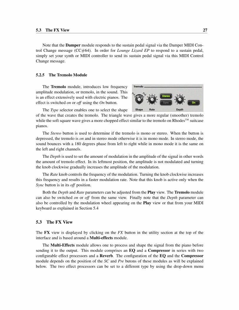
5.2.5 The Tremolo Module
The Tremolo module, introduces low frequencyamplitude modulation, or tremolo, in the sound. Thisis an effect extensively used with electric pianos. Theeffect is switched on or off using the On button.
The Type selector enables one to select the shapeof the wave that creates the tremolo. The triangle wave gives a more regular (smoother) tremolowhile the soft square wave gives a more chopped effect similar to the tremolo on RhodesTM suitcasepianos.
The Stereo button is used to determine if the tremolo is mono or stereo. When the button isdepressed, the tremolo is on and in stereo mode otherwise it is in mono mode. In stereo mode, thesound bounces with a 180 degrees phase from left to right while in mono mode it is the same onthe left and right channels.
The Depth is used to set the amount of modulation in the amplitude of the signal in other wordsthe amount of tremolo effect. In its leftmost position, the amplitude is not modulated and turningthe knob clockwise gradually increases the amplitude of the modulation.
The Rate knob controls the frequency of the modulation. Turning the knob clockwise increasesthis frequency and results in a faster modulation rate. Note that this knob is active only when theSync button is in its off position.
Both the Depth and Rate parameters can be adjusted from the Play view. The Tremolo modulecan also be switched on or off from the same view. Finally note that the Depth parameter canalso be controlled by the modulation wheel appearing on the Play view or that from your MIDIkeyboard as explained in Section 5.4
5.3 The FX View
The FX view is displayed by clicking on the FX button in the utility section at the top of theinterface and is based around a Multi-effects module.
The Multi-Effects module allows one to process and shape the signal from the piano beforesending it to the output. This module comprises an EQ and a Compressor in series with twoconfigurable effect processors and a Reverb. The configuration of the EQ and the Compressormodule depends on the position of the SC and Pre butons of these modules as will be explainedbelow. The two effect processors can be set to a different type by using the drop-down menu

28 Parameters
located at the center of each module for a wide range of possibilities. The effect list includes aDelay, Distortion, Chorus, Flanger, Phaser, Wah Wah, Auto Wah and a Notch filter.
The Multi-Effects module is also visible from the Play view just below the utility section. Thisallows one to see rapidly which effects are selected for a given sound, turn the effects on or off andrapidly adjust the amount of each effect. The Compressor, Equalizer and Reverb can also beadjusted from this view.
5.3.1 EQ
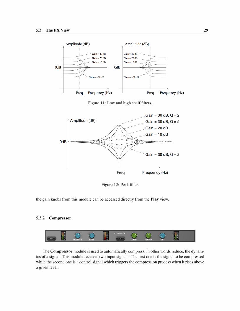
The EQ module provides equalization over the low, mid, and high frequency bands. It is composedof a low shelf filter, two peak filters, and a high shelf filter in series, labelled LF, LMF, HMF, andHF respectively.
The functioning of the low shelf filter is depicted in Figure 11. The filter applies a gain factor tolow frequency components located below a cutoff frequency while leaving those above unchanged.The cutoff frequency of this filter is adjusted using the Freq knob and can vary between 40 and 400Hz. The Gain knob is used to adjust the gain factor applied to the signal in a ±15dB range. Inits center position there is no attenuation (0 dB). Turning it clockwise boosts the amplitude of lowfrequencies while turning it anti-clockwise reduces it.
The high frequency content of the signal is controlled with a high shelf filter that works inthe opposite manner as the low shelf filter as illustrated in Figure 11. The filter applies a gainfactor to components located above a cutoff frequency while leaving those below unchanged. Thecutoff frequency of this filter, located above 1 kHz, is adjusted with the help of the Freq knobwhile the gain factor applied to the signal, in a ±15dB range, is adjusted using Gain knob. In itscenter position there is no attenuation (0 dB). Turning it clockwise boosts the amplitude of highfrequencies while turning it anti-clockwise reduces it.
The EQ module features two peak filters, labeled LMF and HMF, allowing to shape the signalin two frequency bands as illustrated in Figure 12. The filters apply a gain factor to frequencycomponents in a band located around the cutoff frequency of the filters. This cutoff frequency isadjusted using the Freq knob and can vary between 100 Hz and 10 kHz. The gain factor applieda the cutoff frequency is controlled by the Gain knob and can vary in a ±15 dB range. Whenin its center position there is no attenuation (0 dB). Turning it clockwise boosts the amplitude offrequencies located around the cutoff frequency while turning it anti-clockwise reduces it. TheQ knob is used to adjust the so-called quality factor of the filter which controls the width of thefrequency band on which the filter is active. In its leftmost position, the frequency band is wideand it gets narrower as the knob is turned clockwise.
The SC button (side-chain) is used to determine if the output from the EQ module is to be usedas the control signal of the Compressor module as described in Section 5.3.2. Finally, note that all
5.3 The FX View 29
Figure 11: Low and high shelf filters.
Figure 12: Peak filter.
the gain knobs from this module can be accessed directly from the Play view.
5.3.2 Compressor
The Compressor module is used to automatically compress, in other words reduce, the dynam-ics of a signal. This module receives two input signals. The first one is the signal to be compressedwhile the second one is a control signal which triggers the compression process when it rises abovea given level.

30 Parameters
Tuning
The level at which the Compressor starts to enter into action is determined by the value of theThreshold parameter. This value is in dB and corresponds to the amplitude of the input signal asmonitored by the first level meter of the module.
The amount of compression applied to the part of the signal exceeding the threshold valuedepends on the Ratio parameter which varies between value of 1:1 and 1:16. This parameterrepresents the ratio, in dB, between the portion of the output signal from the compressor abovethe threshold value and the portion of its input signal also exceeding the threshold value. As onemight expect, increasing the ratio also increases the amount of compression applied to the signal.For example, a ratio of 1:5 means that if the input signal exceeds the threshold by 5 dB, the outputsignal will exceed the threshold by only 1 dB. Note that the Ratio parameter can also be adjustedfrom the Play view.
Two other controls affect the behavior of the Compressor. The Attack knob is used to set thetime, in milliseconds, before the Compressor fully kicks in after the level of the input has exceededthe threshold value. A short value means that the compressor will reach the amount of compressionas set by the Ratio knob rapidly. With a longer attack, this amount will be reached more gradually.In other words, the attack time is a measure of the attack transient time of the compression effect.The Release parameter is similar and represents the amount of time taken by the Compressor tostop compressing once the amplitude of the input signal falls below the threshold value.
The Makeup knob is used to adjust the overall level at the output of the Compressor moduleand is used to compensate from an overall change in signal level due to the compression effect.
The location of the Compressor in the signal path depends on the setting of the Pre button.When this knob is on, the Compressor is located at the output from the piano, just before the EQmodule. In this position, the input signal of the Compressor and its control signal are both theoutput signal from the piano. When the Pre button is off, the Compressor is located after the EQmodule. In this configuration, the control signal of the Compressor is then the output signal fromthe EQ module. The input signal to the compressor is determined by the position of the SC button.When it is on, the Compressor is in a side-chain configuration. The input of the Compressor isthen the output signal from the piano. When it is off, the input of the Compressor is the outputsignal from the EQ module.
Using the compressor in side chain configuration is useful when one wants to trigger the com-pressor using other criteria than the general level of the signal to be compressed. For example, asound with a lot of bass would easily trigger the Compressor when playing low notes. In orderto avoid that, the EQ module would be set to filter out low frequency components. This signalwould then be used to control the Compressor while the input signal to the Compressor wouldstill include these low frequency components.
The attenuation or gain reduction level meter, located in the middle of the module, indicatesthe amount of compression applied by the module. It is the difference between the input and outputsignals of the module before makeup gain is applied.

5.3 The FX View 31
5.3.3 Delay
The Delay module consists in a stereo feedback loop with a variable delay in the feedback. It isused to produce an echo effect when the delay time is long (greater than 100 ms) or to color thesound when the delay time is short (smaller than 100 ms).
The Delay knob is used to adjust the amount of delay, in seconds, introduced by the effect.Turning this knob clockwise increases the delay. The Feedback parameter is a gain factor, varyingin the range between 0 and 1, applied to the signal at the end of the delay lines. It controls theamount of signal that is re-injected in the feedback loop. In its leftmost position, the value of thisparameter is 0 and no signal is re-introduced in the delay line which means that the signal is onlydelayed once. Turning the knob clockwise increases the amount of signal re-injected at the end ofthe feedback loop and therefore allows one to control the duration of the echo for a given delaytime. In its rightmost position, the gain coefficient is equal to 1 which means that all the signal isre-injected into the feedback loop and that the echo will not stop. In addition to this gain factor,low pass filtering can also be applied to the signal re-injected into the feedback loop. The cutofffrequency of this filter is controlled using the Cutoff knob.
The Pan knob is used to balance the input signal between the left and right channels. In itsleftmost position, signal will only be fed into the left delay line and one will hear clearly definedecho first from the left channel and then from the right channel and so on. In its rightmost position,the behavior will be similar but with the first echo coming from the right channel. These twoextreme position correspond to the standard ping pong effect but a a less extreme behavior can beobtained by choosing an intermediate position. In particular when the Pan knob is in its centerposition, an equal amount of signal is sent in both channels.
The output signal from the Delay module can include a mix of input signal (dry) and delayedsignal (wet). The Wet and Dry knobs are used to adjust the amplitude of each component in thefinal output. The amplitude of each component is increased by turning the corresponding knobclockwise from no signal to an amplitude of +6dB. Note that the Wet parameter is also adjustablefrom the Play view.
5.3.4 Distortion
The Multi-Effect module includes three different types of distortion which are selected using theShape selector knob. The Warm Tube effect applies a smooth symmetrical wave shaping to theinput signal resulting in the introduction of odd harmonics in the signal. The Metal distortion issimilar to the Warm Tube effect but is slightly asymmetrical resulting in the introduction of evenand odd harmonics in the signal. The Solid State distortion applies an aggressive symmetricalclipping to the signal thereby adding high frequency harmonics and resulting in a harsh sound.

32 Parameters
The Drive control is a gain knob acting on the input signal. This parameter allows one to adjustthe amount of distortion introduced in the signal by controlling how rapidly the signal reachesthe non-linear portion of the distortion curve applied on the signal. In its leftmost position, theamplitude of the input signal is reduced by -6 dB; turning this knob clockwise allows one to increaseits amplitude. Note that the Drive parameter is also adjustable from the Play view.
The Tone knob is used to adjust the color of the signal after the distortion algorithm has beenapplied. In its leftmost position, high frequencies will be attenuated in the signal while in itsrightmost position low frequencies will be filtered out from the signal. In its center position, thesignal will be left unchanged.
The Volume knob is a gain knob acting on the amplitude of the distorted signal. Finally, the Mixknob allows one to control the amount of dry and wet (distorted) signal in the final output signalfrom the Distortion module. In its leftmost position, there is only dry signal in the output whilein its rightmost position one only hears the distorted signal. In its center position, there is an equalamount of dry and wet signal in the output.
5.3.5 Chorus
The chorus effect is used to make a source sound like many similar sources played in unison. Itsimulates the slight variations in timing and pitch of different performers executing the same part.The effect is obtained by mixing the original signal with delayed version obtained from the outputof delay lines as shown in Figure 13. In the case of a chorus effect, the length of the delay lines mustbe short in order for the delayed signals to blend with the original signal rather than be perceived asa distinct echo. The length of the delay line can be modulated introducing a slight perceived pitchshift between the voices.
Tuning
The amount of modulation of the length of the delay lines is adjusted using the Depth knob. In theleft position, there is no modulation and the length of the delay lines remains constant. As the knobis turned to the right, the length of the delay line starts to oscillate by an amount which increasesas the knob is turned clockwise thereby increasing the amount by which the different voices aredetuned. The frequency of the modulation is fixed with the Rate knob.

5.3 The FX View 33
Figure 13: Chorus module.
The Fat button is used to control the number of voices in the chorus effect. Switching this buttonon increases the number of voices. The Spread knob is used to adjust the amount of dispersion ofthe different voices in the stereo field. When in its leftmost position, there is an equal amount of leftand right output signal on each channel. In other words the signal is the same on both channels. Inits rightmost position, there is complete separation between the channels, the left output from thechorus is only sent to the left channel while the right output of the chorus is only sent to the rightchannel. Finally, the Mix knob allows one to mix the dry and wet signals. In its leftmost position,there is no output signal from the chorus and one only ears the dry input signals. In its rightmostposition, one only ears the wet signal from the chorus module. In its center position, there is anequal amount of dry and wet signal in the output signal from the module.
5.3.6 Flanger
The Flanger module implements the effect known as flanging which colors the sound with a falsepitch effect caused by the addition of a signal of varying delay to the original signal.
The algorithm implemented in this module is shown in Figure 14. The input signal is sent intoa variable delay line. The output of this delay is then mixed with the dry signal and re-injected intothe delay line with a feedback coefficient.
The effect of the Flanger module is to introduce rejection in the spectrum of the input signal at

34 Parameters
Figure 14: Flanger algorithm.
frequencies located at odd harmonic intervals of a fundamental frequency as shown in Figure 15.The location of the fundamental frequency f0 and the spacing between the valleys and peaks ofthe frequency response is determined by the length of the delay line (f0 = 1/(2delay)), the longerthe delay, the lower is f0 and the smaller the spacing between the harmonics while decreasing thedelay increases f0 and hence the distance between the harmonics.
Figure 15: Frequency response of a Flanger module. Effect of the length of the delay line.
The amount of effect is determined by the ratio of wet and dry signal mixed together as shownin Figure 16. As the amount of wet signal sent to the output is increased, the amount of rejectionincreases. Finally, the shape of the frequency response of the Flanger module is also influencedby the amount of wet signal re-injected into the feedback loop as shown in Figure 17. Increasingthe feedback enhances frequency components least affected by the delay line and located at evenharmonic intervals of the fundamental frequency. As the feedback is increased, these peaks becomesharper resulting in an apparent change in the pitch of the signal.

5.3 The FX View 35
Figure 16: Effect of the mix between wet and dry signal on the frequency response of a Flangermodule
Figure 17: Effect of the amount of feedback on the frequency response of a Flanger module.
Tuning
The delay length, in milliseconds, is adjusted with the Delay knob. The length of this delay can bemodulated by a certain amount depending on the adjustment of the Depth knob. In the left position,there is no modulation and the length of the delay line remains constant. As the knob is turned tothe right, the length of the delay line starts to oscillate by an amount which increases as the knob isturned clockwise and at a frequency fixed with the Rate knob. The Feedback knob is a gain knobused to fix the ratio of wet signal re-injected into the delay. Finally, the Mix knob determines theamount of dry and wet signal in the output signal from the module. When this knob is adjusted inits leftmost position, only dry signal is sent to the output, in its center position, there is an equalamount of dry and wet signal in the output signal while in its rightmost position, only wet signal issent to the output. Note that the Depth parameter is also adjustable from the Play view.

36 Parameters
5.3.7 Phaser
The Phaser module implements the effect known as phasing which colors a signal by removingfrequency bands from its spectrum. The effect is obtained by changing the phase of the frequencycomponents of a signal using an all-pass filter and adding this new signal to the original one.
The algorithm implemented in this module is shown in Figure 18. The input signal is sent into avariable all-pass filter. This wet signal is then mixed down with the original dry signal. A feedbackline allows the resulting signal to be re-injected into the filter. The effect of the Phaser module isto introduce rejection in the spectrum of the input signal depending on the tuning of the filter.
Figure 18: Phaser algorithm.
The all-pass filter modifies a signal by delaying its frequency components with a delay whichincreases with the frequency. This phase variations will introduce a certain amount of cancellationwhen this wet signal is mixed down with the original dry signal as shown in Figure 19. Therejection is maximum when the phase delay is equal to 180 degrees and a given component is outof phase with that of the original signal. The amount of effect is determined by the ratio of wet anddry signal mixed together as shown in Figure 19. As the amount of wet signal sent to the output isreduced, the amount of rejection increases. The shape of the frequency of the Phaser module is alsoinfluenced by the amount of wet signal re-injected into the feedback loop. Increasing the feedbackenhances frequency components least affected by the all-pass filter. As the feedback is increased,these peaks become sharper. The functioning of the Phaser is very similar to that of the Flanger

5.3 The FX View 37
module. The filtering effect is different however, since the Phaser module only introduces rejectionaround a limited number of frequencies which, in addition, are not in an harmonic relationship.
Figure 19: Frequency response of a Phaser module. Effect of the mix between wet and dry signalon the frequency response.
Tuning
The location of the first notch in the frequency response of the module is adjusted with the Fre-quency knob This frequency can be modulated by an amount controlled with the Depth knob. In itsleftmost position, the location of the first notch is fixed but it starts to oscillate by an amount whichincreases as the Depth knob is turned clockwise. The frequency of the modulation is controlledusing the the Rate knob. The feedback knob is used to fix the amount of wet signal re-injected intothe delay. Finally, the Mix knob determines the amount of dry and wet signal sent to the output.When this knob is adjusted in the left position, only dry signal is sent to the output, in its centerposition, there is an equal amount of dry and wet signal in the output and in the right position, onlywet signal is sent to the output.
5.3.8 Wah
The Multi-Effect module includes 2 different types of Wah effects: wah wah, and auto wah. Theseeffects are used to enhance a frequency band around a varying center frequency using a bandpassfilter. In the wah wah effect, the center frequency of the bandpass filter varies at a rate fixed bythe user. In the case of the auto-wah, the variations of the center frequency is controlled by theamplitude envelope of the incoming signal.

38 Parameters
The Freq knob is used to control the central frequency of the filter. Turning this knob clockwiseincreases the center frequency. In the case of the Wah Wah effect, the center frequency will oscillatearound the value fixed by the Freq knob while with the Auto Wah effect, the setting of the Freq willfix the starting point value of the varying center frequency.
The Depth knob controls the excursion of the center frequency of the filter. In the case ofthe Wah Wah effect, this excursion is applied around the value fixed by the Freq knob while inAuto Wah effect the value of the center frequency increases from the value fixed by the Freq knob.Turning this knob clockwise increases the excursion of the center frequency. Note that the Depthparameter is also adjustable from the Play view.
Finally, the Rate knob controls the frequency or rate of the modulation of the center frequencyof the filter. In the case of the Wah Wah effect, turning this knob clockwise increases the rate ofthe modulation. In the case of the Auto Wah filter, this knob is labeled Speed and controls the timeconstant of the envelope follower. Turning this knob clockwise decreases the time constant, or inother words the reaction time, of the envelope follower.
5.3.9 Notch Filter
The Notch Filter does essentially the opposite of a band-pass filter. It attenuates the frequenciesin a band located around the center frequency and leaves those outside of this band unchanged asshown in Figure 20. As was the case for the Wah Wah effect, the filter can be modulated.
The Freq knobs is used to control the central frequency of the filter. Turning this knob clock-wise increases the center frequency. The Depth knob controls the excursion of the center frequencyof the filter around its center frequency. Turning this knob clockwise increases the excursion of thecenter frequency. Finally, the Rate knob controls the frequency or rate of the modulation of thecenter frequency of the filter. Turning this knob clockwise increases the rate of the modulation.Note that the Depth parameter is also adjustable from the Play view.

5.3 The FX View 39
Figure 20: Frequency response of a notch filter.
5.3.10 Reverb
The Reverb effect is used to recreate the effect of reflections of sound on the walls of a room orhall. These reflections add space to the sound and make it warmer, deeper, as well as more realisticsince we always listen to instruments in a room and thus with a room effect.
Impulse Response of a Room
The best way to evaluate the response of a room is to clap hands and to listen to the resultingsound. Figure 21 shows the amplitude of the impulse response of a room versus time. The firstpart of the response is the clap itself, the direct sound, while the remaining of the response is theeffect of the room which can itself be divided in two parts. Following the direct sound, one canobserve a certain amount of echoes which gradually become closer and closer until they can not bedistinguished anymore and can be assimilated to an exponentially decaying signal. The first partof the room response is called the early reflexion while the second is called the late reverberation.The total duration of the room response is called the reverberation time (RT).
Adjusting the room effect
The size of a room strongly affects the reverberation effect. The Size selector is used to choose be-tween the Studio, Club, Hall and Large Hall settings each reproducing spaces of different volumesfrom smaller to larger.

40 Parameters
Figure 21: Impulse response of a room.
The duration of the reverberation time depends on both the size of the room and the absorptionof the walls, which is controlled with the Decay knob. In a real room the reverberation time is notconstant over the whole frequency range. As the walls are often more absorbent in the very low andin the high frequencies the reverberation time is shorter for these frequencies. These parametersare adjusted with the Low and High knobs respectively.
Another parameter which affects the response of a room is its geometry; the more complexthe geometry of a room, the more reflexion are observed per unit of time. This quantity is knownas the time density and can be set trough the Diffusion knob. In a concert hall, the time densityis supposed to be quite high in order not to hear separate echoes which are characteristic of poorsounding rooms. The last parameter which affects our listening experience in a room, is the distance
between the sound source and the listener. While the room response is quite constant regardless ofthe position of the source and the listener, the direct sound (the sound which comes directly fromthe source) depends strongly on the position of the listener. The farther we are from the soundsource the quieter is the direct sound relatively to the room response. The ratio between the directsound and the room response is adjusted with the Mix knob which in other words is used to adjustthe perceived distance between the source and the listener. In its leftmost position, only the directsound is heard while when fully turned to the right, one only hears the room response. Note thatthe Mix parameter is also adjustable from the Play view.

5.4 The Play View 41
5.4 The Play View
The Play view groups together the main parameters from the Edit and FX views. It is loaded whenstarting the instrument and can be accessed from another view by clicking on the Play button onthe top part of the interface.
The middle section of this view allows one to switch on and off the EQ, Compressor andReverb as well as the active effect modules. Key effect parameters are also adjustable as presentedin the description of the different effect modules in section 5.3
The lower part of this view is dedicated to piano parameters. Key controls are provided asdescribed in section 5.2. This section also includes a so-called Character parameter that is onlyaccessible from this view. This parameter provides five (5) classic studio and stage signal pathemulations, in other words the speaker, cabinet, pre-amp, microphone and recorder chain thatfollow the piano output and give different colors to the original piano sound. When this knobis in its leftmost position, no profile is applied and one can hear the direct output from the piano.Turning this knob to the right allows one to choose between the five different profiles which varyfrom less to more pronounce in character. Adding character might not always be necessary but itmay help to find your sound to find its right place in a mix.
Pitch Wheel
The MIDI pitch wheel allows one to vary the pitch of the piano. The pitch wheel can be movedwith the mouse but it is also automatically connected to the pitch wheel signal received from yourMIDI keyboard.
The range of the pitch bend is 2 semi-tones up or down by default but can be changed. Toadjust the range of the pitch bend, open the MIDI configuration window by clicking on the MIDIbutton located just below the MIDI let in the top part of the interface and use the Pitch Bend Rangedrop-down menu to select the range in semi-tones.

42 Utility Section
Modulation Wheel
The modulation wheel is linked to the Depth parameter of the Tremolo module. It can be activatedon screen or from the modulation wheel of your MIDI controller (MIDI controller number 1). Bydefault, the modulation wheel is inactive. The value of the Depth parameter of the Tremolo moduleis then fixed by the value saved in the currently loaded program. Upon touching the modulationwheel, the Trem switch located below the wheel, starts to blink. Once this switch is turned on, thevalue of the Depth parameter follows the position of the modulation wheel. Note that the positionof the Trem switch is not saved in a program which means that once it is turned on, it will remainso until it is switched off even if new programs are loaded.
Ribbon
The lower part of this view includes a ribbon controller. The ribbon covers seven octaves and notesare played when clicking on the ribbon. The ribbon is useful to test sounds when no MIDI keyboardis connected to your computer.
6 Utility Section
The utility section is located at the top of the Lounge Lizard EP interface and it includes importantparameters and monitoring tools. For information on Banks and Programs please refer to Chapter 4
6.1 The MIDI LED
The MIDI LED is located on the left of the level-meter. The LED blinks when the synthesizerreceives MIDI signal. If the application is not receiving MIDI signal, make sure that the hostsequencer is sending MIDI to Lounge Lizard EP. If you are running in standalone mode, make surethat the MIDI controller you wish to use is well connected to your computer and that it is selectedas explained in Section 7.
6.2 Polyphony
The Voices control located in the upper left corner of this section allows one to adjust the numberof polyphony voices used by Lounge Lizard EP. The number of voices is adjusted by clicking onthe control and selecting the desired number of voices. In general, a higher number of voices isdesirable but keep in mind that the CPU load is proportional to the number of voices used.

6.3 Tuning 43
6.3 Tuning
The Tune control, located to the right of the MIDI LED, is used to transpose the frequency of thekeyboard. This control is composed of two numbers separated by a dot. The first number indicatesa value in semi-tones while the second one indicates a value in cents (one hundredth of a semi-tone). The amount of transposition can be adjusted by click-dragging upward or downward on thesemi-tone and cent controls. Double clicking on these controls brings back their value to zero.When the value of the Tune parameters is set to 0.00, the frequency of notes are calculated relativeto A4 with a frequency of 440Hz.
An interesting feature of Lounge Lizard EP is that it can be tuned using different tempera-ments using Scala micro-tuning files. Temperament files are loaded by clicking on the Tune buttonwhich opens the Tuning pop-up window and displays the list of available tuning temperament filesavailable.
By default, Lounge Lizard EP is set to stretched Temperament but equal temperament is alsoinstalled. Other files can be added to the list by copying them to the following folders:
On Mac OS:/Users/[user name]/Library/Application Support/Applied Acoustics Systems/Scala Tunings/
On Windows:%AppData%\Applied Acoustics Systems\Scala Tunings\
These folders can be displayed directly from Lounge Lizard EP by clicking on the Show TuningFiles button at the bottom of the Tuning pop-up window.
Selecting a Scala file in the list automatically triggers the loading of the corresponding temper-ament. The reference note that will be used as the base note for the scale described in the Scala filecan be set using the Reference Note control appearing at the bottom of the Tuning window. Thefrequency of this reference note is calculated relative to the settings of the Tune control. Please notethat the reference note does not appear in the window when the default temperament is chosen, itonly appears once a Scala file is loaded.
6.4 History and Compare
The History control allows one to go back through all the modifications that were made to programssince the application was started. In order to travel back and forth in time, use the left and right-pointing arrows respectively. The application will switch between different program states andindicate the time at which they were modified.
The Compare button, located above the Program display, is used to switch between Edit andCompare mode. This button is visible only once a modification is applied to a given program. Itallows one to revert to the original version of a program in order to compare it with the currentversion. When in Compare mode, edition is blocked and it is therefore not possible to modify anyparameter. The Compare mode must then be switched off by clicking on the Compare button inorder to resume edition.

44 Utility Section
6.5 Volume
The Volume knob is the master volume of the application. It is used to adjust the overall level ofthe output signal from the synthesizer. General level is increased by turning the knob clockwise.
6.6 Level Meter
The level meter allows one to monitor peak and RMS (root means square) level of the left (L)and right (R) output channels from the synthesizer. As a limiter is located at the output of LoungeLizard EP, it is important to make sure that the amplitude of the signal remains within values thatensure that no distortion is introduced in the signal at the output.
The 0 dB mark on the level meter has been adjusted to correspond to -20 dBFS (full scale). Thismeans that at that level, the signal is -20 dB below the maximum allowed value. This 0 dB levelmark should typically correspond to playing at mezzo forte (moderately loud) level. This ensuresa headroom of 20 dB which should be more than enough to cover the dynamics of most playingsituations and therefore guarantee that no additional distortion is added in the output signal.
A peak value mark allows one to follow the maximum level values reached by the output signal.The limiter is triggered when this mark enters the red zone of the level meter (17 dB) and it remainsactive while the side vertical bars at the top of the lever meter are switched On.
6.7 The About Box
The About box is open by clicking on the chevrons located at the very top of the interface or onthe product or company logo. The box is closed by clicking again on the chevrons or outside thebox. Useful information is displayed in this box such as the program’s version number, the serialnumber that was used for the authorization and the the email address that was used for registration.The box also includes a link to the pdf version of this manual.

Audio and MIDI Settings 45
7 Audio and MIDI Settings
This chapter explains how to select and configure Audio and MIDI devices used by Lounge LizardEP. Audio and MIDI configuration tools are accessed by clicking on the Audio Setup button locatedin the lower left corner of the Lounge Lizard EP interface and the MIDI button located just belowthe MIDI led in upper part of the interface.
Note that in plug-in mode the audio and MIDI inputs, sampling rate, and buffer size are set bythe host sequencer.
7.1 Audio Configuration
7.1.1 Selecting an Audio Device
Audio configuration tools are available by clicking on the Audio Setup button located in the lowerleft corner of the Lounge Lizard EP interface. The Audio Setup dialog first allows you to selectan audio output device from those available on your computer. Multi-channel interfaces will havetheir outputs listed as stereo pairs.
On Windows, the audio output list is organized by driver type. The device type is first selectedfrom the Audio Device Type drop-down list. If you have ASIO drivers available, these should beselected for optimum performance. The Configure Audio Device button allows you to open themanufacturer’s setup program for your audio interface when available.
Once the audio input has been selected, you can then select a sampling rate and a buffer sizefrom those offered by your audio interface.
7.1.2 Latency
The latency is the time delay between the moment you send a control signal to your computer (forexample when you hit a key on your MIDI keyboard) and the moment when you hear the effect.Roughly, the latency will be equal to the duration of the buffers used by the application and thesound card to play audio and MIDI. To calculate the total time required to play a buffer, just dividethe number of samples per buffer by the sampling frequency. For example, 256 samples playedat 48 kHz represent a time of 5.3 ms. Doubling the number of samples and keeping the samplingfrequency constant will double this time while changing the sampling frequency to 96 kHz andkeeping the buffer size constant will reduce the latency to 2.7 ms.
It is of course desirable to have as little latency as possible. Lounge Lizard EP however requiresa certain amount of time to be able to calculate sound samples in a continuous manner. This timedepends on the power of the computer used, the preset played, the sampling rate, and the numberof voices of polyphony used. Note that it will literally take twice as much CPU power to processaudio at a sampling rate of 96 kHz as it would to process the same data at 48 kHz, simply becauseit is necessary to calculate twice as many samples in the same amount of time.

46 Audio and MIDI Settings
Depending on your machine you should choose, for a given sampling frequency, the smallestbuffer size that allows you to keep real-time for a reasonable number of voices of polyphony.
7.2 MIDI Configuration
7.2.1 Selecting a MIDI Device
The list of available MIDI inputs appears at the bottom of the Audio Setup dialog. Click on theAudio Setup button located in the lower left corner of the Lounge Lizard EP interface and then clickon the checkbox corresponding to any of the inputs you wish to use.
7.2.2 Creating MIDI Links
Every control on the Lounge Lizard EP interface can be manipulated by an external MIDI controllerthrough MIDI control change assignments. In most cases this is much more convenient than usingthe mouse, especially if you want to move many controllers at once. For example, you can map themotion of a knob on the interface to a real knob on a knob box or to the modulation wheel fromyour keyboard. As you use the specified MIDI controllers, you will see the controls move on theLounge Lizard EP interface just as if you had used the mouse.
In order to assign a MIDI link to a controller:
• On the Lounge Lizard EP interface, right-click/Control-click on a control (knob, button) andselect the MIDI Learn command.
• Move a knob or slider on your MIDI controller (this can be a keyboard, a knob box, or anydevice that sends MIDI). This will link the control of the Lounge Lizard EP to the MIDIcontroller you just moved.
To deactivate a MIDI link, simply righ-click/Control-click on the corresponding control on theLounge Lizard EP interface and select the MIDI Forget command.
7.2.3 Creating a default MIDI Map
It is possible to define a a set of MIDI links, called a MIDI map, that will be loaded automaticallywhen Lounge Lizard EP is launched. Once you have defined a set of MIDI links that you wish tosave, click on MIDI button to open the MIDI configuration window and click on the Save Currentas Default button.
If you make changes to MIDI links after opening the program and wish to revert to the defaultMIDI map click on MIDI button to open the MIDI configuration window and click on the LoadDefault button.
If you wish to deactivate all the MIDI links at once open the MIDI configuration window andclick on the Clear MIDI Map button.

7.2 MIDI Configuration 47
7.2.4 MIDI Program Changes
Lounge Lizard EP responds to MIDI program changes. When a program change is received, thecurrent program is changed to the program having the same number as that of the program changemessage in the currently loaded bank.
If you do not wish Lounge Lizard EP to respond to MIDI program changes, open the MIDIconfiguration window by clicking on the MIDI button and uncheck the Enable Program Changesoption.
7.2.5 MIDI Bank Changes
In general, MIDI bank numbers are coded using two signals: the MSB (most significant byte) andLSB (least significant byte) transmitted using MIDI CC (continuous controller) number 0 and 32respectively. The way these signals are used differs with different manufacturers.
In the case of Lounge Lizard EP, the value of the MSB signal is expected to be zero while thevalue of the LSB signal represents the bank number. Banks are therefore numbered from 0 to 127with this number corresponding to the position of a bank within the list of banks as displayed bythe Bank manager (see Section 4.3). For example, an LSB value of 0 corresponds to the first bankin the bank list while an LSB value of 10 corresponds to the eleventh bank in the list. Note that abank change only becomes effective after the reception of a new MIDI program change signal.
If you do not wish Lounge Lizard EP to respond to MIDI bank changes, open the MIDI config-uration window by clicking on the MIDI button and uncheck the Enable Bank Changes option.
7.2.6 Pitch bend
The MIDI pitch wheel allows one to vary the pitch of Lounge Lizard EP. The pitch wheel can bemoved with the mouse but it is also automatically connected to the pitch wheel signal receivedfrom your MIDI keyboard.
The range of the pitch bend is 2 semi-tones up or down by default but can be changed. To adjustthe range of the pitch bend, open the MIDI configuration window by clicking on the MIDI buttonlocated just below the MIDI led in the top part of the interface and use the Pitch Bend Rangedrop-down list to select the range in semi-tones.
7.2.7 Modulation wheel
Lounge Lizard EP responds to MIDI modulation (MIDI controller number 1). For more details,please refer to Section 5.4.

48 Using Lounge Lizard EP as a Plug-In
8 Using Lounge Lizard EP as a Plug-In
Lounge Lizard EP is available in VST, RTAS and AudioUnit formats and integrates seamlesslyinto the industry most popular multi-track recording and sequencing environments as a virtualinstrument plug-in. Lounge Lizard EP works as any other plug-in in these environments so werecommend that you refer to your sequencer documentation in case you have problems running itas a plug-in. We review here some general points to keep in mind when using a plug-in version ofLounge Lizard EP.
8.1 Audio and MIDI Configuration
When Lounge Lizard EP is used as a plug-in, the audio and MIDI ports, sampling rate, buffer size,and audio format are determined by the host sequencer.
8.2 Automation
Lounge Lizard EP supports automation functions of host sequencers. All parameters visible on theinterface can be automatized except for the Polyphony, Bank, Program and History commands.
8.3 Multiple Instances
Multiple instances of Lounge Lizard EP can be launched simultaneously in a host sequencer.
8.4 MIDI Program Change
MIDI program changes are supported in Lounge Lizard EP. When a MIDI program change is re-ceived by the application, the current program used by the synthesis engine is changed to thathaving the same number, in the currently loaded bank, as that of the MIDI program change mes-sage.
8.5 Saving Projects
When saving a project in a host sequencer, the currently loaded program is saved with the projectin order to make sure that the instrument will be in the same state as when you saved the projectwhen you re-open it. Note that banks of programs are not saved with the project which implies thatif you are using MIDI program changes in your project, you must make sure that the bank you areusing in your project still exists on your disk when you reload the project. The programs must alsoexist and be in the same order as when the project was saved.

8.6 Performance 49
8.6 Performance
Using a plug-in in a host sequencer requires CPU processing for both applications. The load on theCPU is even higher when multiple instances of a plug-in or numerous different plug-ins are used.To decrease CPU usage, remember that you can use the freeze or bounce to track functions of thehost sequencer in order to render to audio the part played by a plug-in instead of recalculating itevery time it is played.

50 License Agreement
9 License Agreement
IMPORTANT! CAREFULLY READ ALL THE TERMS AND CONDITIONS OF THIS AGREE-MENT BEFORE OPENING THIS PACKAGE. OPENING THIS PACKAGE INDICATES YOURACCEPTANCE OF THESE TERMS AND CONDITIONS. IF YOU DO NOT AGREE WITHTHE TERMS AND CONDITIONS OF THIS AGREEMENT, PROMPTLY RETURN THE UN-OPENED PACKAGE AND ALL COMPONENTS THERETO TO THE PARTY FROM WHOMIT WAS ACQUIRED, FOR A FULL REFUND OF ANY CONSIDERATION PAID.
This software program, any printed materials, any on-line or electronic documentation, and anyand all copies of such software program and materials (the “Software”) are the copyrighted workof Applied Acoustics Systems DVM Inc. (“AAS”), its subsidiaries, licensors and/or its suppliers.
1. LICENSE TO USE. The Licensee is granted a personal, non-exclusive and non-transferablelicense to install and to use one copy of the Software on a single computer solely for thepersonal use of the Licensee. Use of the Software is subject to this Agreement.
2. RESTRICTIONS ON USE. The Licensee may not nor permit third parties to (i) make copiesof any portion of the Software, other than as expressly permitted under this Agreement; (ii)modify, translate, disassemble, decompile, reverse engineer or create derivative and/or com-petitive products based on any portion of the Software; (iii) provide use of the Software in anetwork, timesharing, interactive cable television, multiple CPU service bureau or multipleuser arrangement to users not individually licensed by AAS, other than as expressly permit-ted by the terms of this license. The Software is licensed to you as a single product. Itscomponent parts may not be separated for use on more than one computer.
3. OWNERSHIP. AAS retains title to the Software, including but not limited to any titles,computer code, themes, objects dialog concepts, artwork, animations, sounds, audio effects,methods of operation, moral rights, any related documentation and “applets” incorporatedinto the Software. AAS retains ownership of and title to all intellectual property rights in theSoftware, underlying technology, related written materials, logos, names and other supportmaterials furnished either with the Software or as a result of this Agreement, including butnot limited to trade secrets, patents, trademarks and copyrights therein. Licensee shall notremove or alter any copyright or other proprietary rights notices contained on or within theSoftware and shall reproduce such notices on all copies thereof permitted under this Agree-ment or associated documentation.
4. LIMITED WARRANTY. Except for the foregoing, THE SOFTWARE IS provided “AS IS”without warranty or condition of any kind. AAS disclaims all warranties or conditions, writ-ten or oral, statutory, express or implied, including but not limited to the implied warranties ofmerchantable quality or fitness for a particular purpose, title and non-infringement of rightsof any other person. AAS does not warrant that THE SOFTWARE will meet the Licensee’srequirements or that the operation of the software will be uninterrupted or ERROR-FREE.

License Agreement 51
5. LIMITATION OF LIABILITY. TO THE MAXIMUM EXTENT PERMITTED BY APPLI-CABLE LAW, IN NO EVENT WILL AAS BE LIABLE TO THE LICENSEE OR ANYTHIRD PARTY FOR ANY INDIRECT, SPECIAL, CONSEQUENTIAL, INCIDENTALOR EXEMPLARY DAMAGES WHATSOEVER, INCLUDING BUT NOT LIMITED TOLOSS OF REVENUE OR PROFIT, LOST OR DAMAGED DATA, BUSINESS INTER-RUPTION OR ANY OTHER PECUNIARY LOSS WHETHER BASED IN CONTRACT,TORT OR OTHER CAUSE OF ACTION, EVEN IF AAS HAS BEEN ADVISED OF THEPOSSIBILITY OF SUCH DAMAGES, EXCEPT IN RELATION TO GROSS NEGLIGENCEOR WILFUL BREACH OF THIS AGREEMENT BY AAS. NO AAS AGENT, REPRE-SENTATIVE OR DEALER IS AUTHORIZED TO EXTEND, MODIFY OR ADD TO THISWARRANTY ON BEHALF OF AAS. THE TOTAL LIABILITY OF AAS FOR DAM-AGES, WHETHER IN CONTRACT OR TORT, UNDER OR RELATED IN ANY WAY TOTHIS AGREEMENT SHALL BE LIMITED TO THE LICENSE FEES ACTUALLY PAIDBY LICENSEE TO AAS, OR IF NO FEES WERE PAID, AAS’ LIST PRICE FOR THESOFTWARE COVERED BY THIS LICENSE. THE EXCLUSION OF IMPLIED WAR-RANTIES AND/OR THE LIMITATION OF LIABILITY IS NOT PERMITTED IN SOMEJURISDICTIONS, AND SOME OR ALL OF THESE EXCLUSIONS MAY THEREFORENOT APPLY.
6. TERMINATION. This License also shall extend to the Software and any updates or newreleases thereof obtained by the Licensee, if any, subject to any changes to this License madeby AAS from time to time and provided to the Licensee, provided AAS is under a separateobligation to provide to Licensee such updates or upgrades and Licensee continues to have avalid license which is in effect at the time of receipt of each such update or new release. ThisLicense shall remain in effect until terminated. The Licensee may terminate this Agreementat any time, upon notification to AAS. This Agreement will terminate immediately withoutnotice from AAS if the Licensee fails to comply with any provision of this License. Anysuch termination by AAS shall be in addition to and without prejudice to such rights andremedies as may be available, including injunction and other equitable remedies. Uponreceipt of notice of termination from AAS, the Licensee must (a) immediately cease to usethe Software; (b) destroy all copies of the Software, as well as copies of all documentation,specifications and magnetic media relating thereto in Licensee’s possession or control; and(c) return all original versions of the Software and associated documentation. The provisionsof Sections 1, 3, and 5 shall survive the termination of this Agreement.
7. GOVERNING LAW. This Agreement shall be governed by and construed in accordance withthe laws of the Province of Quebec, without regard to the United Nations Convention OnContracts for the International Sale of Goods and conflict of laws provisions, if applicable,and the parties hereby irrevocably attorn to the jurisdiction of the courts of that province. Lesparties sont d’accord a ce que cette convention soit redigee en langue anglaise. The partieshave agreed that this agreement be drafted in the English language.
8. SEVERABILITY. If any of the above provisions are held to be illegal, invalid or unenforce-able, such provision shall be severed from this Agreement and this Agreement shall not be
52 License Agreement
rendered inoperative but the remaining provisions shall continue in full force and effect.
9. ENTIRE AGREEMENT. This Agreement is the entire agreement between AAS and theLicensee relating to the Software and: (i) supersedes all prior or contemporaneous oral orwritten communications, proposals and representations with respect to its subject matter; and(ii) prevails over any conflicting or additional terms of any quote, order, acknowledgement,or similar communication between the parties during the term of this Agreement except asotherwise expressly agreed by the parties. No modification to the Agreement will be binding,unless in writing and signed by a duly authorized representative of each party.
10. NON-WAIVER. No delay or failure to take any action or exercise any rights under thisAgreement shall constitute a waiver or consent unless expressly waived or consented to inwriting by a duly authorized representative of AAS. A waiver of any event does not apply toany other event, even if in relation to the same subject-matter.

Indexabout, 44architecture, 14audio, 45
configuration, 10, 45device, 45latency, 45
authorization, 7auto-wah, 14, 27, 37
backup, 19bank, 17
backup, 19create, 17delete, 17factory library, 20rename, 17sharing, 19
bank manager, 17buffer size, 10, 45
challenge code, 7character, 41chorus, 14, 27, 32
mono, 32stereo, 32
clock, 22coarse, 21compare, 43compressor, 14, 27, 29contact, 11cpu load, 42
damper, 26sustain pedal, 27
default MIDI map, 46delay, 14, 27, 31distortion, 31, 44drop-down menus, 21
edit view, 14, 22effect
synchronization, 22effect view, 14EQ, 28equalizer, 14, 27
factory library, 10fine tuning, 21flanger, 14, 27, 33fork, 24fx view, 14, 27
hammer, 22force, 23noise, 23stiffness, 22
help, 9, 11history, 12, 43
installation, 7interface, 21
drop-down menus, 21knobs, 21numerical displays, 21switches, 21
knobs, 21
latency, 45level meter, 44lfo
synchronization, 22library
restore, 20limiter, 44
manual, 44master volume, 44micro-tuning, 43MIDI, 45
bank change, 47configuration, 10, 46

54 INDEX
device, 46link map, 46links, 46pitch bend, 41, 47program change, 17, 19, 47receiving, 42
MIDI controller, 46MIDI led, 42minimum system requirements, 6modulation, 21modulation wheel, 14, 42modules, 21multi-effect, 14, 27
auto wah, 37chorus, 32delay, 31distortion, 31EQ, 28flanger, 33notch filter, 38phaser, 36reverb, 39synchronization, 22wah wah, 37
notch filter, 14, 27, 38numerical displays, 21
overdrive, 31
parameters, 21peak, 44phaser, 14, 27, 36pickup, 25pitch bend, 14, 47pitch wheel, 41play view, 14, 41plug-in, 11
audio configuration, 48automation, 48formats, 48MIDI configuration, 48MIDI program change, 48
multiple instances, 48performance, 49saving projects, 48
polyphony, 7, 42programs, 10, 17
backup, 19bank manager, 17copy, 17factory library, 20move, 17saving, 17sharing, 19
registration, 7release, 26release time, 25response code, 7restore factory library, 20reverb, 14, 39ribbon, 14, 42
sampling rate, 7, 10save, 17save as, 17sc, 29scala files, 43signal flow, 14solid state, 31standalone, 9start-up, 9sustain pedal, 26, 27switches, 21synchronization, 22system requirements, 6
tine, 24tone, 24transpose, 43tremolo, 14, 27tuning, 43
unlocking, 7utility section, 42

INDEX 55
voices, 42volume, 44VU meter, 44
wah wah, 14, 27, 37warm tube, 31