![Analysis Report [PDF 3MB]](https://static.fdocuments.net/doc/165x107/5868c7b61a28ab27408c0702/analysis-report-pdf-3mb.jpg)
USER MANUAL (3mb)
41
Certified to CE O123; EN795 B in 3 & 4 leg configurations for maximum 2 persons. User Manual Version 4.0
Transcript of USER MANUAL (3mb)

Certified to CE O123; EN795 B in 3 & 4 leg configurations for maximum 2 persons.
User Manual
Version 4.0
Arachnipod User Manual Date: 19 March 2010 Version: 4.0 Page 2 of 41 © Copyright: FERNO AUSTRALIA
Table of Contents
Introduction ................................................................................................................................... 3 Safe Working Loads ...................................................................................................................... 4 Dimensions and Weight ................................................................................................................ 4 Tripod and Kit Contents ................................................................................................................ 5 Safe Working Practices ................................................................................................................. 7 Principles of Edge Management ................................................................................................... 7 Critical Point Analysis (high change of direction) .......................................................................... 8 The Two Rope System.................................................................................................................. 9 Arachnipod Parts ........................................................................................................................ 10 Bridge Systems ........................................................................................................................... 14 Arachnipod Assembly ................................................................................................................. 15
Step 1. Preparation ................................................................................................................. 15 Step 2. Assemble legs ............................................................................................................ 15 Step 3. Tether the Arachnipod and move it into position ........................................................ 17 Step 4. Extend the legs ........................................................................................................... 17 Step 5. Position the legs ......................................................................................................... 18 Step 6. Secure the legs ........................................................................................................... 18 Step 7. Assess the resultant force and direction ..................................................................... 18 Step 8. Provide additional rigging as required ........................................................................ 18 Step 9. Rig a two rope system wherever possible .................................................................. 18 Step 10. Carry out a safety check ........................................................................................... 19 Step 11. Weight the system and recheck the resultant ........................................................... 19 Step 12. Monitor the Arachnipod for stability .......................................................................... 19
Anchoring the Arachnipod ........................................................................................................... 19 Using an Arachnipod leg as an anchor ....................................................................................... 19 Understanding the forces being applied to the Arachnipod ........................................................ 20 Assessing the stability of your Arachnipod rigging ...................................................................... 20 Tripod Stabilisation ..................................................................................................................... 21 Tripod Stabilisation ..................................................................................................................... 22 Lazy Leg Tripod Stabilisation ...................................................................................................... 23 Quadpod Stabilisation ................................................................................................................. 24 A-Frame Stabilisation .................................................................................................................. 25 Gin Pole Stabilisation .................................................................................................................. 28 Using a single leg to manage a handrail ..................................................................................... 29 Bridge Stabilisation ..................................................................................................................... 30 Foot Options for your Arachnipod ............................................................................................... 31 General ....................................................................................................................................... 32 Inspection of the Arachnipod ...................................................................................................... 32 Safety Information ....................................................................................................................... 32 Repairs ........................................................................................................................................ 32 Care, Maintenance and Storage ................................................................................................. 33 Life Cycle .................................................................................................................................... 33 Additional Accessories for your Arachnipod ................................................................................ 34 Inspection and Maintenance Records ......................................................................................... 39 Regular Checking Procedures and Inspection ............................................................................ 40
Arachnipod User Manual Date: 19 March 2010 Version: 4.0 Page 3 of 41 © Copyright: FERNO AUSTRALIA
Introduction
Congratulations on your purchase of the Arachnipod. The Arachnipod is a total edge management system that will empower the end user with a wide range of configuration options. The complete Arachnipod (TEMS) system can be rigged as a:
• Gin Pole (mono pole / monopod) • A-frame (bipod) • Sideways A-frame (SA-frame) • Tripod • Quadpod • Lazy Leg or Easel Leg Tripod • Handrail monopod (used to support to a handrail) • Bridge
Components can be added or removed as required so that the Arachnipod compliments existing structural or natural features making it the most versatile edge management solution on the planet. Ferno understands that rigging is not always conducted on a flat surface or with a clean edge so the Arachnipod was designed with every conceivable task in mind. From the harshest vertical rescue conditions to a simple tripod for a confined space entry task, the Arachnipod will provide the flexibility that end users demand. The versatility of the Arachnipod will appeal to a wide range of end users including rescuers, mines rescue, industrial rope access workers, construction, and film industries. The end user can purchase as little or as much Arachnipod hardware to suit their scope of operations making the Arachnipod an edge management system that is both affordable and upgradeable to suit changes in operational needs. With the appropriate training, the Arachnipod can be used in a variety of configurations and in any number of environments from wilderness applications to industrial rope access scenarios.
Arachnipod User Manual Date: 19 March 2010 Version: 4.0 Page 4 of 41 © Copyright: FERNO AUSTRALIA
Safe Working Loads
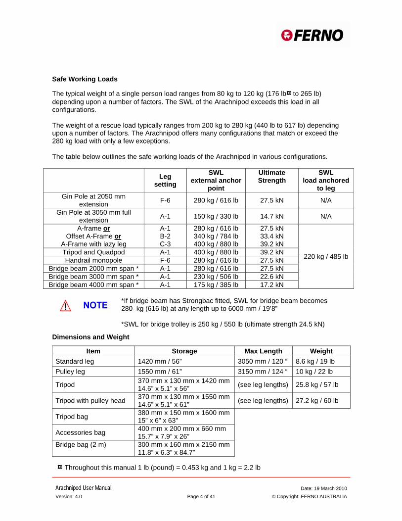
The typical weight of a single person load ranges from 80 kg to 120 kg (176 lb¤ to 265 lb) depending upon a number of factors. The SWL of the Arachnipod exceeds this load in all configurations. The weight of a rescue load typically ranges from 200 kg to 280 kg (440 lb to 617 lb) depending upon a number of factors. The Arachnipod offers many configurations that match or exceed the 280 kg load with only a few exceptions. The table below outlines the safe working loads of the Arachnipod in various configurations.
Configurations Leg setting
SWL external anchor
point
Ultimate Strength
SWL load anchored
to leg Gin Pole at 2050 mm
extension F-6 280 kg / 616 lb 27.5 kN N/A
Gin Pole at 3050 mm full extension A-1 150 kg / 330 lb 14.7 kN N/A
A-frame or Offset A-Frame or
A-Frame with lazy leg
A-1 B-2 C-3
280 kg / 616 lb 340 kg / 784 lb 400 kg / 880 lb
27.5 kN 33.4 kN 39.2 kN
220 kg / 485 lb Tripod and Quadpod A-1 400 kg / 880 lb 39.2 kN Handrail monopole F-6 280 kg / 616 lb 27.5 kN
Bridge beam 2000 mm span * A-1 280 kg / 616 lb 27.5 kN Bridge beam 3000 mm span * A-1 230 kg / 506 lb 22.6 kN Bridge beam 4000 mm span * A-1 175 kg / 385 lb 17.2 kN
*If bridge beam has Strongbac fitted, SWL for bridge beam becomes 280 kg (616 lb) at any length up to 6000 mm / 19’8” *SWL for bridge trolley is 250 kg / 550 lb (ultimate strength 24.5 kN)
Dimensions and Weight
Item Storage Max Length Weight Standard leg 1420 mm / 56” 3050 mm / 120 “ 8.6 kg / 19 lb Pulley leg 1550 mm / 61” 3150 mm / 124 “ 10 kg / 22 lb
Tripod 370 mm x 130 mm x 1420 mm 14.6” x 5.1” x 56” (see leg lengths) 25.8 kg / 57 lb
Tripod with pulley head 370 mm x 130 mm x 1550 mm 14.6” x 5.1” x 61” (see leg lengths) 27.2 kg / 60 lb
Tripod bag 380 mm x 150 mm x 1600 mm 15” x 6” x 63”
Accessories bag 400 mm x 200 mm x 660 mm 15.7” x 7.9” x 26”
Bridge bag (2 m) 300 mm x 160 mm x 2150 mm 11.8” x 6.3” x 84.7”
¤ Throughout this manual 1 lb (pound) = 0.453 kg and 1 kg = 2.2 lb
Arachnipod User Manual Date: 19 March 2010 Version: 4.0 Page 5 of 41 © Copyright: FERNO AUSTRALIA
Tripod and Kit Contents
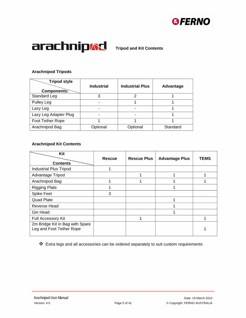
Arachnipod Tripods
Tripod style
Components:
Industrial
Industrial Plus
Advantage
Standard Leg 3 2 1 Pulley Leg - 1 1 Lazy Leg - - 1 Lazy Leg Adapter Plug - - 1 Foot Tether Rope 1 1 1 Arachnipod Bag Optional Optional Standard
Arachnipod Kit Contents
Kit
Contents
Rescue
Rescue Plus Advantage Plus TEMS
Industrial Plus Tripod 1 Advantage Tripod 1 1 1 Arachnipod Bag 1 1 1 1 Rigging Plate 1 1 Spike Feet 3 Quad Plate 1 Reverse Head 1 Gin Head 1 Full Accessory Kit 1 1 2m Bridge Kit in Bag with Spare Leg and Foot Tether Rope
1
Extra legs and all accessories can be ordered separately to suit custom requirements
Arachnipod User Manual Date: 19 March 2010 Version: 4.0 Page 6 of 41 © Copyright: FERNO AUSTRALIA
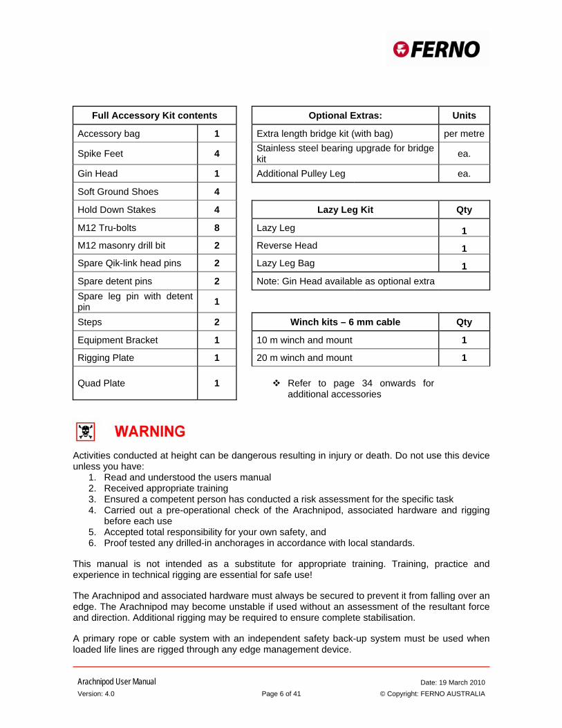
Full Accessory Kit contents Optional Extras: Units
Accessory bag 1 Extra length bridge kit (with bag) per metre
Spike Feet 4 Stainless steel bearing upgrade for bridge kit ea.
Gin Head 1 Additional Pulley Leg ea.
Soft Ground Shoes 4 Hold Down Stakes 4 Lazy Leg Kit Qty
M12 Tru-bolts 8 Lazy Leg 1 M12 masonry drill bit 2 Reverse Head 1 Spare Qik-link head pins 2 Lazy Leg Bag 1 Spare detent pins 2 Note: Gin Head available as optional extra Spare leg pin with detent pin 1 Steps 2 Winch kits – 6 mm cable Qty
Equipment Bracket 1 10 m winch and mount 1
Rigging Plate 1 20 m winch and mount 1
Quad Plate 1
Refer to page 34 onwards for
additional accessories
Activities conducted at height can be dangerous resulting in injury or death. Do not use this device unless you have:
1. Read and understood the users manual 2. Received appropriate training 3. Ensured a competent person has conducted a risk assessment for the specific task 4. Carried out a pre-operational check of the Arachnipod, associated hardware and rigging
before each use 5. Accepted total responsibility for your own safety, and 6. Proof tested any drilled-in anchorages in accordance with local standards.
This manual is not intended as a substitute for appropriate training. Training, practice and experience in technical rigging are essential for safe use! The Arachnipod and associated hardware must always be secured to prevent it from falling over an edge. The Arachnipod may become unstable if used without an assessment of the resultant force and direction. Additional rigging may be required to ensure complete stabilisation. A primary rope or cable system with an independent safety back-up system must be used when loaded life lines are rigged through any edge management device.
Arachnipod User Manual Date: 19 March 2010 Version: 4.0 Page 7 of 41 © Copyright: FERNO AUSTRALIA
Safe Working Practices
1. Do not exceed the safe working load for the given application. 2. Always maintain a safety line independent of the main line. 3. All Arachnipod feet must be secured to prevent unwanted movement. 4. It is a good practice to ensure that all rigging is capable of holding the entire weight of the
main load. 5. Always provide height safety and fall prevention for personnel working close to the height
risk.
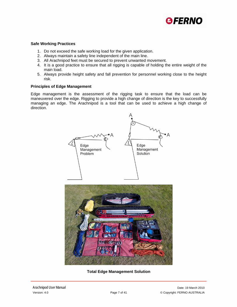
Principles of Edge Management
Edge management is the assessment of the rigging task to ensure that the load can be maneuvered over the edge. Rigging to provide a high change of direction is the key to successfully managing an edge. The Arachnipod is a tool that can be used to achieve a high change of direction.
Total Edge Management Solution
Arachnipod User Manual Date: 19 March 2010 Version: 4.0 Page 8 of 41 © Copyright: FERNO AUSTRALIA
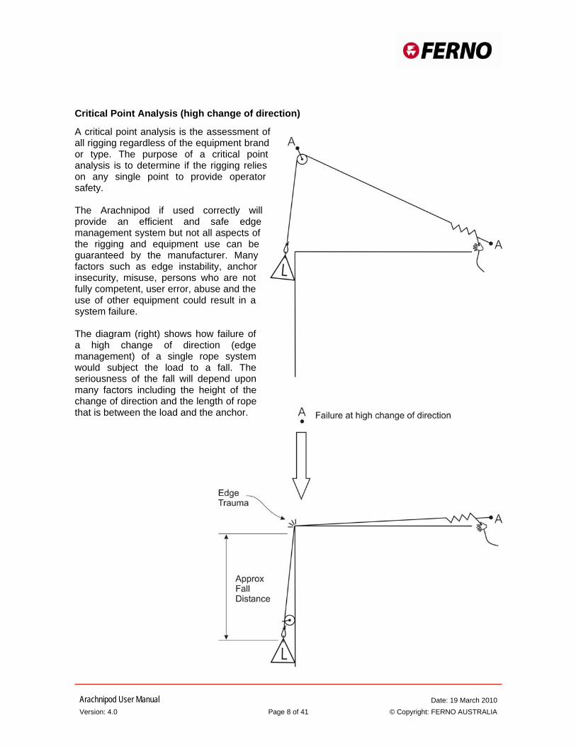
Critical Point Analysis (high change of direction)
A critical point analysis is the assessment of all rigging regardless of the equipment brand or type. The purpose of a critical point analysis is to determine if the rigging relies on any single point to provide operator safety. The Arachnipod if used correctly will provide an efficient and safe edge management system but not all aspects of the rigging and equipment use can be guaranteed by the manufacturer. Many factors such as edge instability, anchor insecurity, misuse, persons who are not fully competent, user error, abuse and the use of other equipment could result in a system failure. The diagram (right) shows how failure of a high change of direction (edge management) of a single rope system would subject the load to a fall. The seriousness of the fall will depend upon many factors including the height of the change of direction and the length of rope that is between the load and the anchor.

Arachnipod User Manual Date: 19 March 2010 Version: 4.0 Page 9 of 41 © Copyright: FERNO AUSTRALIA
The Two Rope System
A two rope system provides additional safety by backing up the main line and any edge management systems. The second line or safety line is rigged to take the shortest path from the anchor to the load.
When the load is located below the edge the safety line provides protection for both main line and edge management failures. When the load is located above the edge the safety line provides limited protection for main line failures.
The Arachnipod can be rigged with the main line passing over the pulley head and a rated hauling system can be used to progressively pick the safety line up as the load is raised. This process provides additional protection against a main line failure. Ferno can supply properly rated and pre-rigged hauling systems that are suitable for this task.
Edge protection should also be provided to protect both lines against edge trauma. Ferno can supply a range of edge protection solutions.
Arachnipod User Manual Date: 19 March 2010 Version: 4.0 Page 10 of 41 © Copyright: FERNO AUSTRALIA
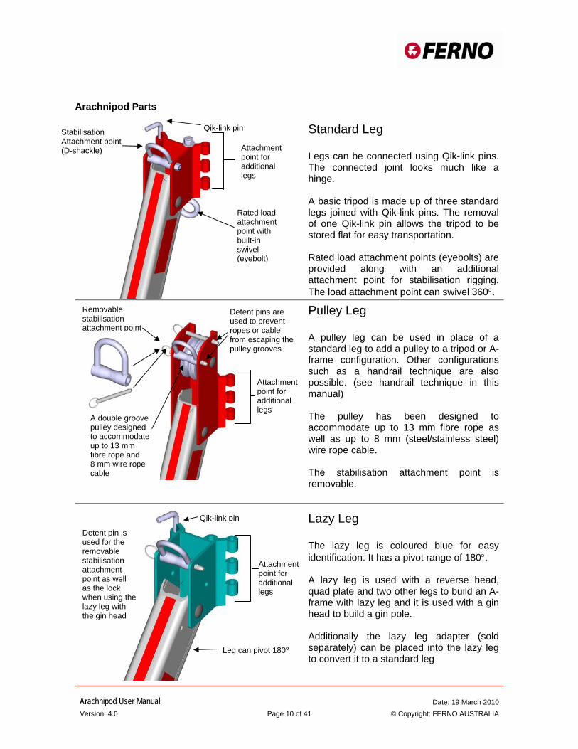
Arachnipod Parts
Standard Leg Legs can be connected using Qik-link pins. The connected joint looks much like a hinge. A basic tripod is made up of three standard legs joined with Qik-link pins. The removal of one Qik-link pin allows the tripod to be stored flat for easy transportation. Rated load attachment points (eyebolts) are provided along with an additional attachment point for stabilisation rigging. The load attachment point can swivel 360°.
Pulley Leg A pulley leg can be used in place of a standard leg to add a pulley to a tripod or A-frame configuration. Other configurations such as a handrail technique are also possible. (see handrail technique in this manual) The pulley has been designed to accommodate up to 13 mm fibre rope as well as up to 8 mm (steel/stainless steel) wire rope cable. The stabilisation attachment point is removable.
Lazy Leg The lazy leg is coloured blue for easy identification. It has a pivot range of 180°. A lazy leg is used with a reverse head, quad plate and two other legs to build an A-frame with lazy leg and it is used with a gin head to build a gin pole. Additionally the lazy leg adapter (sold separately) can be placed into the lazy leg to convert it to a standard leg
Stabilisation Attachment point (D-shackle)
Qik-link pin
Attachment point for additional legs
Rated load attachment point with built-in swivel (eyebolt)
Removable stabilisation attachment point
A double groove pulley designed to accommodate up to 13 mm fibre rope and 8 mm wire rope cable
Detent pins are used to prevent ropes or cable from escaping the pulley grooves
Attachment point for additional legs
Detent pin is used for the removable stabilisation attachment point as well as the lock when using the lazy leg with the gin head
Qik-link pin
Attachment point for additional legs
Leg can pivot 180⁰
Arachnipod User Manual Date: 19 March 2010 Version: 4.0 Page 11 of 41 © Copyright: FERNO AUSTRALIA
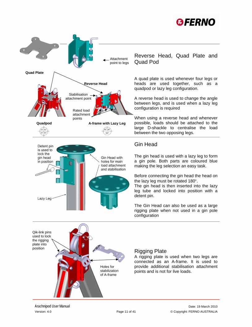
Reverse Head, Quad Plate and Quad Pod A quad plate is used whenever four legs or heads are used together, such as a quadpod or lazy leg configuration. A reverse head is used to change the angle between legs, and is used when a lazy leg configuration is required When using a reverse head and whenever possible, loads should be attached to the large D-shackle to centralise the load between the two opposing legs.
Gin Head The gin head is used with a lazy leg to form a gin pole. Both parts are coloured blue making the leg selection an easy task. Before connecting the gin head the head on the lazy leg must be rotated 180°. The gin head is then inserted into the lazy leg tube and locked into position with a detent pin. The Gin Head can also be used as a large rigging plate when not used in a gin pole configuration
Rigging Plate A rigging plate is used when two legs are connected as an A-frame. It is used to provide additional stabilisation attachment points and is not for live loads.
Qik-link pins used to lock the rigging plate into position
Holes for stabilization of A-frame
Quadpod
Rated load attachment points
Stabilisation attachment point
Quad Plate
Attachment point to legs
Reverse Head
A-frame with Lazy Leg
Arachnipod User Manual Date: 19 March 2010 Version: 4.0 Page 12 of 41 © Copyright: FERNO AUSTRALIA
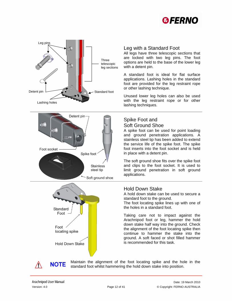
Leg with a Standard Foot All legs have three telescopic sections that are locked with two leg pins. The foot options are held to the base of the lower leg with a detent pin. A standard foot is ideal for flat surface applications. Lashing holes in the standard foot are provided for the leg restraint rope or other lashing technique. Unused lower leg holes can also be used with the leg restraint rope or for other lashing techniques.
Spike Foot and Soft Ground Shoe A spike foot can be used for point loading and ground penetration applications. A stainless steel tip has been added to extend the service life of the spike foot. The spike foot inserts into the foot socket and is held in place with a detent pin. The soft ground shoe fits over the spike foot and clips to the foot socket. It is used to limit ground penetration in soft ground applications.
Hold Down Stake A hold down stake can be used to secure a standard foot to the ground. The foot locating spike lines up with one of the holes in a standard foot. Taking care not to impact against the Arachnipod foot or leg, hammer the hold down stake half way into the ground. Check the alignment of the foot locating spike then continue to hammer the stake into the ground. A soft faced or shot filled hammer is recommended for this task.
Maintain the alignment of the foot locating spike and the hole in the standard foot whilst hammering the hold down stake into position.
Leg pins
Detent pin
Lashing holes
Three telescopic leg sections
Standard foot

Arachnipod User Manual Date: 19 March 2010 Version: 4.0 Page 13 of 41 © Copyright: FERNO AUSTRALIA
Equipment Bracket The equipment bracket must only be used when attached to the middle telescopic leg section. The safe working load of the Arachnipod is reduced to 220 kg when a leg is used as an anchor. This attachment point is only to be used if the main line passes through a change of direction pulley at the head of the tripod.
Steps Steps can be attached to the middle and the lower leg sections. They are a useful aid when reaching high rigging. They are reversible and can be attached to the inside or the outside of a leg. A leg pin is used to secure a step into position. Steps do not carry a rating for any load applications. Before using a step you must ensure that you are secured with suitable height safety rigging and personal protective equipment.
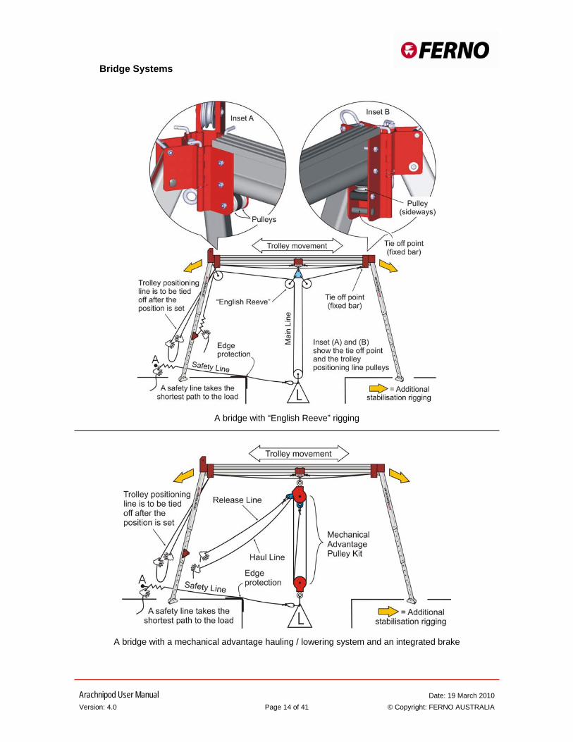
Bridge Beams and Trolley Bridge beams are available in lengths up to 6 m (refer SWL table on page 4 for load rating). They add a spanning capability that is well suited to trench rescue and confined space applications. A trolley is fitted to the bridge beam. The trolley is hauled back and forth along the beam using the trolley positioning line. This is a single person operation. An “English Reeve” is recommended because it negates the need for any additional trolley stabilisation. A tie off point has been included to facilitate “English Reeve” rigging. A mechanical advantage hauling system can be suspended directly from the trolley as long as it includes an integrated braking system to remove lateral forces at times other than when being raised or lowered. The Ferno CSR pulley kit (available separately) is a pre-rigged 4:1 mechanical advantage system incorporating a brake and a remote release for raising and lowering. The trolley positioning line is used for positioning of the trolley.
If any other rigging systems are used then the resultant forces must be considered and additional stabilisation of the trolley and the bridge is required.
Arachnipod User Manual Date: 19 March 2010 Version: 4.0 Page 14 of 41 © Copyright: FERNO AUSTRALIA
A bridge with “English Reeve” rigging
A bridge with a mechanical advantage hauling / lowering system and an integrated brake
Bridge Systems
Arachnipod User Manual Date: 19 March 2010 Version: 4.0 Page 15 of 41 © Copyright: FERNO AUSTRALIA
Arachnipod Assembly
The assembly and rigging process for the Arachnipod depends upon a number of factors including: • The type of Arachnipod kits available • The configuration to be used and • The rigging experience of the user
It is recommended that two or more people work together to assemble the Arachnipod components as follows:
Step 1. Preparation
Select the most appropriate Arachnipod configuration for the task. Establish a staging area where the Arachnipod components can be laid out. A staging area is a location that is in a safe area (away from the fall hazard). A clean tarp is a useful tool for staging. Carry out a pre-operational check of all equipment and do not extend the legs until the heads are connected.
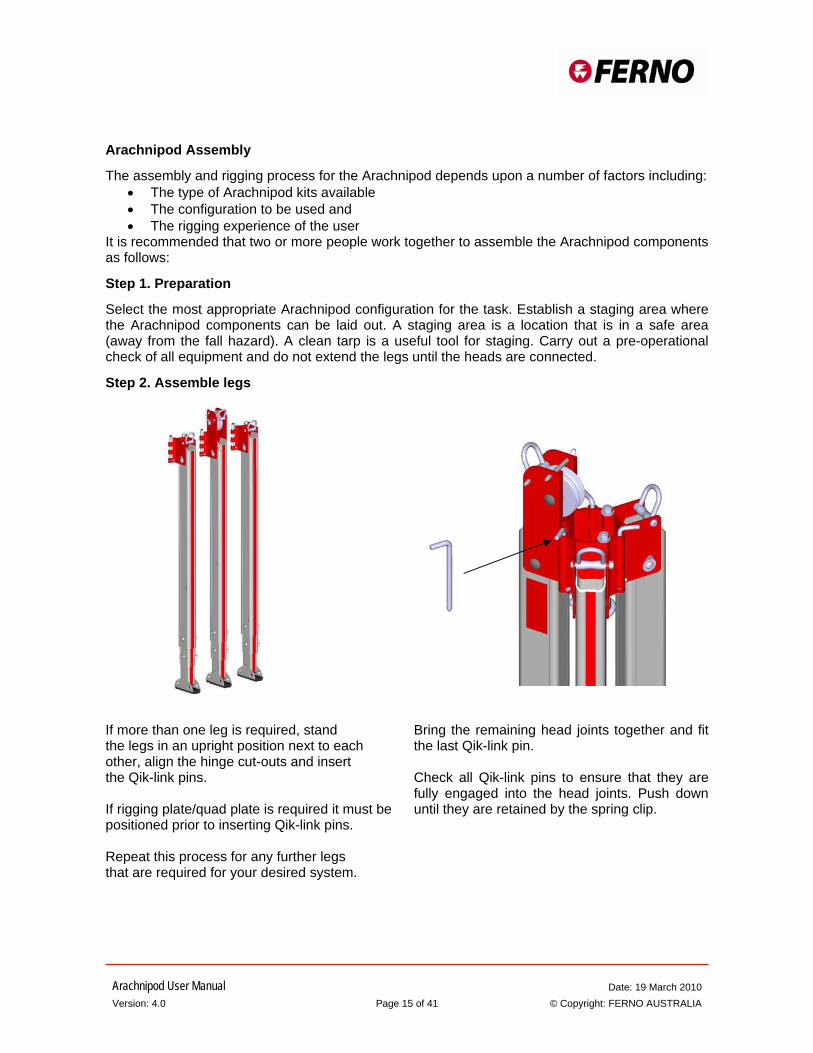
Step 2. Assemble legs
If more than one leg is required, stand the legs in an upright position next to each other, align the hinge cut-outs and insert the Qik-link pins. If rigging plate/quad plate is required it must be positioned prior to inserting Qik-link pins. Repeat this process for any further legs that are required for your desired system.
Bring the remaining head joints together and fit the last Qik-link pin. Check all Qik-link pins to ensure that they are fully engaged into the head joints. Push down until they are retained by the spring clip.
Arachnipod User Manual Date: 19 March 2010 Version: 4.0 Page 16 of 41 © Copyright: FERNO AUSTRALIA
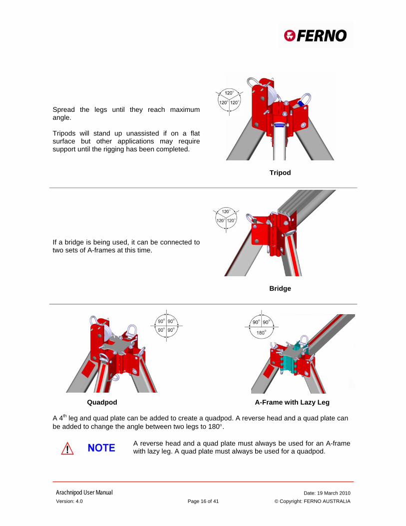
Spread the legs until they reach maximum angle. Tripods will stand up unassisted if on a flat surface but other applications may require support until the rigging has been completed.
Tripod
If a bridge is being used, it can be connected to two sets of A-frames at this time.
Bridge
Quadpod A-Frame with Lazy Leg A 4th leg and quad plate can be added to create a quadpod. A reverse head and a quad plate can be added to change the angle between two legs to 180°.
A reverse head and a quad plate must always be used for an A-frame with lazy leg. A quad plate must always be used for a quadpod.
Arachnipod User Manual Date: 19 March 2010 Version: 4.0 Page 17 of 41 © Copyright: FERNO AUSTRALIA
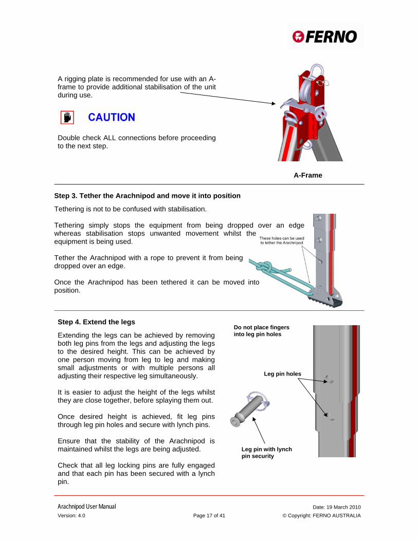
A rigging plate is recommended for use with an A-frame to provide additional stabilisation of the unit during use.
Double check ALL connections before proceeding to the next step.
Step 3. Tether the Arachnipod and move it into position
Tethering is not to be confused with stabilisation. Tethering simply stops the equipment from being dropped over an edge whereas stabilisation stops unwanted movement whilst the equipment is being used. Tether the Arachnipod with a rope to prevent it from being dropped over an edge. Once the Arachnipod has been tethered it can be moved into position.
Step 4. Extend the legs
Extending the legs can be achieved by removing both leg pins from the legs and adjusting the legs to the desired height. This can be achieved by one person moving from leg to leg and making small adjustments or with multiple persons all adjusting their respective leg simultaneously. It is easier to adjust the height of the legs whilst they are close together, before splaying them out. Once desired height is achieved, fit leg pins through leg pin holes and secure with lynch pins. Ensure that the stability of the Arachnipod is maintained whilst the legs are being adjusted. Check that all leg locking pins are fully engaged and that each pin has been secured with a lynch pin.
Do not place fingers
into leg pin holes
Leg pin holes
Leg pin with lynch pin security
A-Frame
Arachnipod User Manual Date: 19 March 2010 Version: 4.0 Page 18 of 41 © Copyright: FERNO AUSTRALIA
Take care with sliding parts. Do not place fingers into holes and watch for pinch points that may be created depending upon the application and the equipment used.
Step 5. Position the legs
Check that the legs are positioned in a secure location and ensure that the most appropriate foot option is being used.
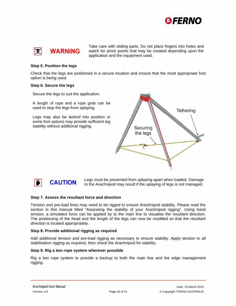
Step 6. Secure the legs
Secure the legs to suit the application. A length of rope and a rope grab can be used to stop the legs from splaying. Legs may also be lashed into position or some foot options may provide sufficient leg stability without additional rigging.
Legs must be prevented from splaying apart when loaded. Damage to the Arachnipod may result if the splaying of legs is not managed.
Step 7. Assess the resultant force and direction
Tension and pre-load lines may need to be rigged to ensure Arachnipod stability. Please read the section in this manual titled “Assessing the stability of your Arachnipod rigging”. Using hand tension, a simulated force can be applied by to the main line to visualise the resultant direction. The positioning of the head and the length of the legs can now be modified so that the resultant direction is located appropriately.
Step 8. Provide additional rigging as required
Add additional tension and pre-load rigging as necessary to ensure stability. Apply tension to all stabilisation rigging as required, then check the Arachnipod for stability.
Step 9. Rig a two rope system wherever possible
Rig a two rope system to provide a backup to both the main line and the edge management rigging.
Arachnipod User Manual Date: 19 March 2010 Version: 4.0 Page 19 of 41 © Copyright: FERNO AUSTRALIA
Step 10. Carry out a safety check
Visually check all anchors, rigging, karabiners, friction devices, harnesses and personal protective equipment before committing anyone to the edge. Edge safety lines must be provided for any persons who are working close to the edge.
Step 11. Weight the system and recheck the resultant
Before committing a load to the edge, the system should be weighted in a safe manner (for example: backed up with a safety line) and the resultant re-checked. This step should be carried out in a manner that allows retrieval of the load if adjustments to the configuration or rigging are needed.
Step 12. Monitor the Arachnipod for stability
There are many factors that can change the physics of the edge management task and as such the stability of the Arachnipod must be constantly monitored. If any instability is detected then the safety line can be set to safely hold the load whilst adjustments are made.
Anchoring the Arachnipod
The number of anchors that will be required depends entirely upon the configuration of the Arachnipod. Safe and secure anchors will be required for:
1. The main line 2. The safety line 3. Edge safety lines (for persons working close to an edge) 4. The initial rope lanyard or tether used to secure the Arachnipod. 5. Each tension line and 6. Each pre-load line
Anchor selection and anchor rigging techniques are not within the scope of this manual.
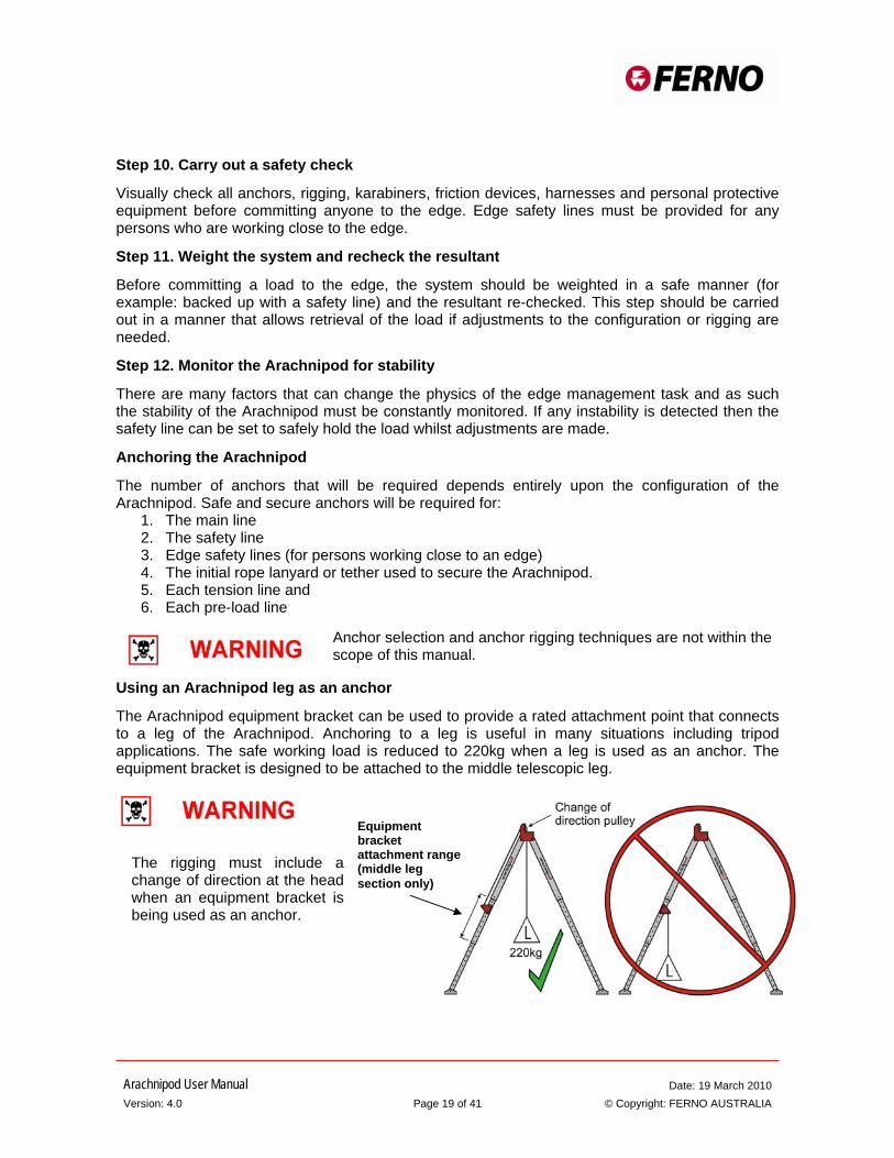
Using an Arachnipod leg as an anchor
The Arachnipod equipment bracket can be used to provide a rated attachment point that connects to a leg of the Arachnipod. Anchoring to a leg is useful in many situations including tripod applications. The safe working load is reduced to 220kg when a leg is used as an anchor. The equipment bracket is designed to be attached to the middle telescopic leg.
Equipment bracket attachment range (middle leg section only)
The rigging must include a change of direction at the head when an equipment bracket is being used as an anchor.
Arachnipod User Manual Date: 19 March 2010 Version: 4.0 Page 20 of 41 © Copyright: FERNO AUSTRALIA
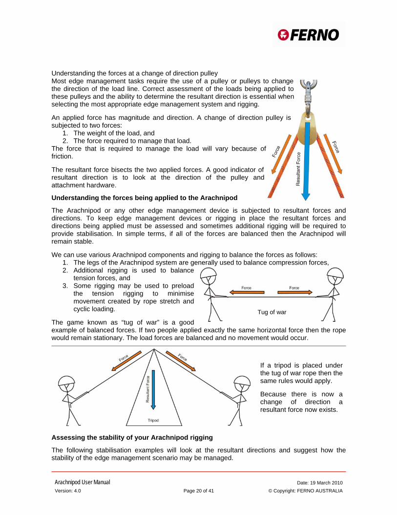
Understanding the forces at a change of direction pulley Most edge management tasks require the use of a pulley or pulleys to change the direction of the load line. Correct assessment of the loads being applied to these pulleys and the ability to determine the resultant direction is essential when selecting the most appropriate edge management system and rigging. An applied force has magnitude and direction. A change of direction pulley is subjected to two forces:
1. The weight of the load, and 2. The force required to manage that load.
The force that is required to manage the load will vary because of friction. The resultant force bisects the two applied forces. A good indicator of resultant direction is to look at the direction of the pulley and attachment hardware.
Understanding the forces being applied to the Arachnipod
The Arachnipod or any other edge management device is subjected to resultant forces and directions. To keep edge management devices or rigging in place the resultant forces and directions being applied must be assessed and sometimes additional rigging will be required to provide stabilisation. In simple terms, if all of the forces are balanced then the Arachnipod will remain stable. We can use various Arachnipod components and rigging to balance the forces as follows:
1. The legs of the Arachnipod system are generally used to balance compression forces, 2. Additional rigging is used to balance
tension forces, and 3. Some rigging may be used to preload
the tension rigging to minimise movement created by rope stretch and cyclic loading.
The game known as “tug of war” is a good example of balanced forces. If two people applied exactly the same horizontal force then the rope would remain stationary. The load forces are balanced and no movement would occur.
If a tripod is placed under the tug of war rope then the same rules would apply. Because there is now a change of direction a resultant force now exists.
Assessing the stability of your Arachnipod rigging
The following stabilisation examples will look at the resultant directions and suggest how the stability of the edge management scenario may be managed.
Tug of war
Arachnipod User Manual Date: 19 March 2010 Version: 4.0 Page 21 of 41 © Copyright: FERNO AUSTRALIA
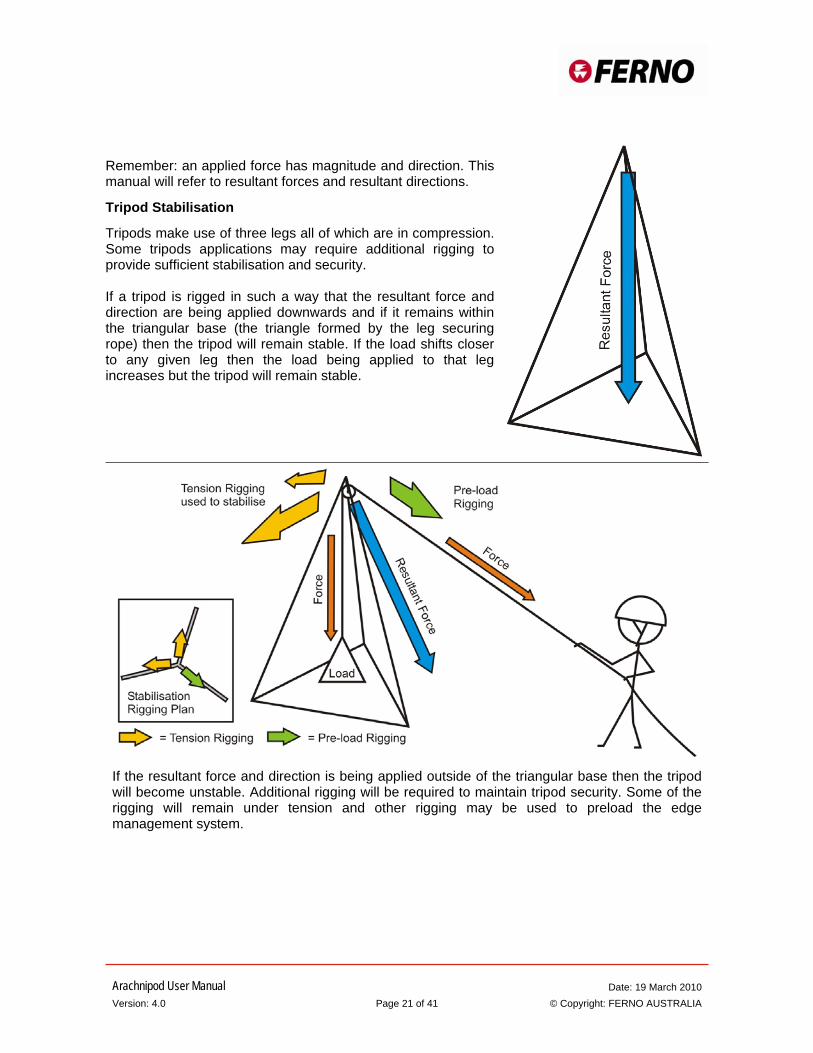
Remember: an applied force has magnitude and direction. This manual will refer to resultant forces and resultant directions.
Tripod Stabilisation
Tripods make use of three legs all of which are in compression. Some tripods applications may require additional rigging to provide sufficient stabilisation and security. If a tripod is rigged in such a way that the resultant force and direction are being applied downwards and if it remains within the triangular base (the triangle formed by the leg securing rope) then the tripod will remain stable. If the load shifts closer to any given leg then the load being applied to that leg increases but the tripod will remain stable.
If the resultant force and direction is being applied outside of the triangular base then the tripod will become unstable. Additional rigging will be required to maintain tripod security. Some of the rigging will remain under tension and other rigging may be used to preload the edge management system.
Arachnipod User Manual Date: 19 March 2010 Version: 4.0 Page 22 of 41 © Copyright: FERNO AUSTRALIA
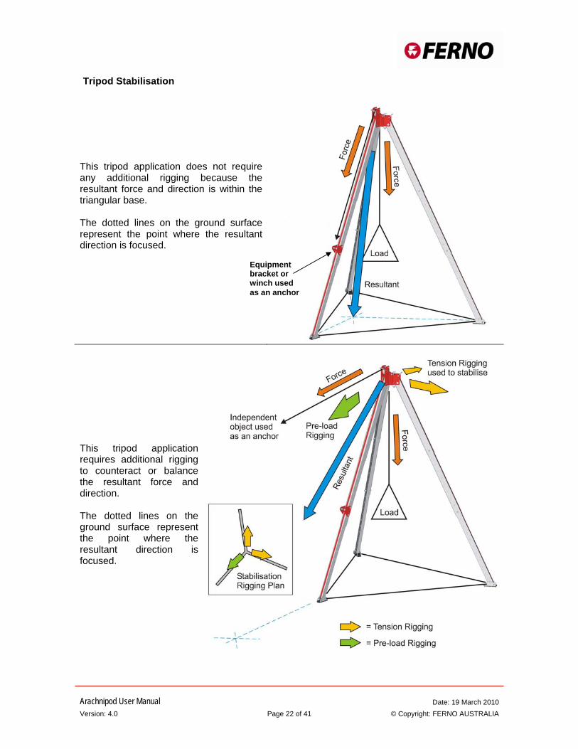
This tripod application does not require any additional rigging because the resultant force and direction is within the triangular base. The dotted lines on the ground surface represent the point where the resultant direction is focused.
This tripod application requires additional rigging to counteract or balance the resultant force and direction. The dotted lines on the ground surface represent the point where the resultant direction is focused.
Equipment bracket or winch used as an anchor
Tripod Stabilisation
Arachnipod User Manual Date: 19 March 2010 Version: 4.0 Page 23 of 41 © Copyright: FERNO AUSTRALIA
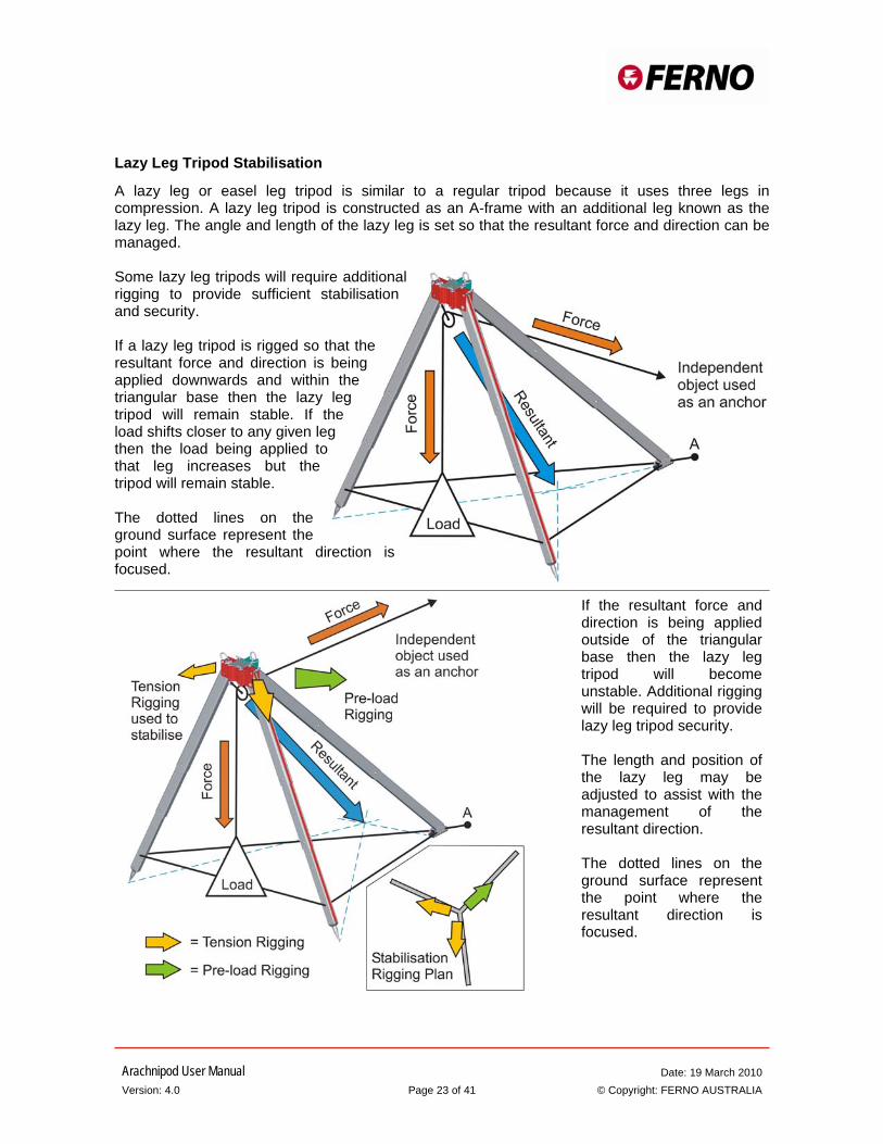
Lazy Leg Tripod Stabilisation
A lazy leg or easel leg tripod is similar to a regular tripod because it uses three legs in compression. A lazy leg tripod is constructed as an A-frame with an additional leg known as the lazy leg. The angle and length of the lazy leg is set so that the resultant force and direction can be managed. Some lazy leg tripods will require additional rigging to provide sufficient stabilisation and security. If a lazy leg tripod is rigged so that the resultant force and direction is being applied downwards and within the triangular base then the lazy leg tripod will remain stable. If the load shifts closer to any given leg then the load being applied to that leg increases but the tripod will remain stable. The dotted lines on the ground surface represent the point where the resultant direction is focused.
If the resultant force and direction is being applied outside of the triangular base then the lazy leg tripod will become unstable. Additional rigging will be required to provide lazy leg tripod security. The length and position of the lazy leg may be adjusted to assist with the management of the resultant direction. The dotted lines on the ground surface represent the point where the resultant direction is focused.
Arachnipod User Manual Date: 19 March 2010 Version: 4.0 Page 24 of 41 © Copyright: FERNO AUSTRALIA
Quadpod Stabilisation
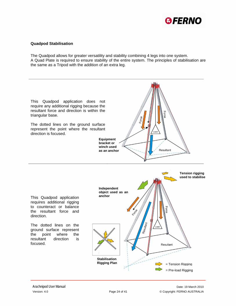
The Quadpod allows for greater versatility and stability combining 4 legs into one system. A Quad Plate is required to ensure stability of the entire system. The principles of stabilisation are the same as a Tripod with the addition of an extra leg.
This Quadpod application requires additional rigging to counteract or balance the resultant force and direction. The dotted lines on the ground surface represent the point where the resultant direction is focused.
This Quadpod application does not require any additional rigging because the resultant force and direction is within the triangular base. The dotted lines on the ground surface represent the point where the resultant direction is focused.
= Tension Rigging
= Pre-load Rigging
Stabilisation Rigging Plan
Independent object used as an anchor
Tension rigging used to stabilise
Equipment bracket or winch used as an anchor
Arachnipod User Manual Date: 19 March 2010 Version: 4.0 Page 25 of 41 © Copyright: FERNO AUSTRALIA
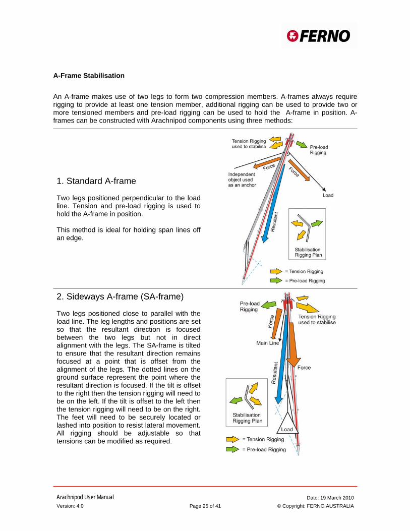
A-Frame Stabilisation
An A-frame makes use of two legs to form two compression members. A-frames always require rigging to provide at least one tension member, additional rigging can be used to provide two or more tensioned members and pre-load rigging can be used to hold the A-frame in position. A-frames can be constructed with Arachnipod components using three methods:
1. Standard A-frame Two legs positioned perpendicular to the load line. Tension and pre-load rigging is used to hold the A-frame in position. This method is ideal for holding span lines off an edge.
2. Sideways A-frame (SA-frame) Two legs positioned close to parallel with the load line. The leg lengths and positions are set so that the resultant direction is focused between the two legs but not in direct alignment with the legs. The SA-frame is tilted to ensure that the resultant direction remains focused at a point that is offset from the alignment of the legs. The dotted lines on the ground surface represent the point where the resultant direction is focused. If the tilt is offset to the right then the tension rigging will need to be on the left. If the tilt is offset to the left then the tension rigging will need to be on the right. The feet will need to be securely located or lashed into position to resist lateral movement. All rigging should be adjustable so that tensions can be modified as required.
Arachnipod User Manual Date: 19 March 2010 Version: 4.0 Page 26 of 41 © Copyright: FERNO AUSTRALIA
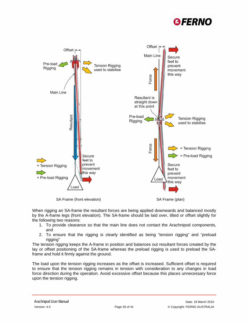
SA Frame (front elevation) SA Frame (plan) When rigging an SA-frame the resultant forces are being applied downwards and balanced mostly by the A-frame legs (front elevation). The SA-frame should be laid over, tilted or offset slightly for the following two reasons:
1. To provide clearance so that the main line does not contact the Arachnipod components, and
2. To ensure that the rigging is clearly identified as being “tension rigging” and “preload rigging”
The tension rigging keeps the A-frame in position and balances out resultant forces created by the lay or offset positioning of the SA-frame whereas the preload rigging is used to preload the SA-frame and hold it firmly against the ground. The load upon the tension rigging increases as the offset is increased. Sufficient offset is required to ensure that the tension rigging remains in tension with consideration to any changes in load force direction during the operation. Avoid excessive offset because this places unnecessary force upon the tension rigging.
Arachnipod User Manual Date: 19 March 2010 Version: 4.0 Page 27 of 41 © Copyright: FERNO AUSTRALIA
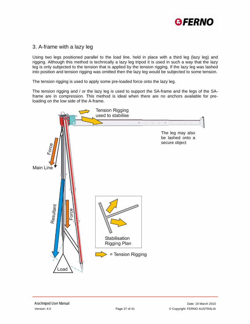
3. A-frame with a lazy leg Using two legs positioned parallel to the load line, held in place with a third leg (lazy leg) and rigging. Although this method is technically a lazy leg tripod it is used in such a way that the lazy leg is only subjected to the tension that is applied by the tension rigging. If the lazy leg was lashed into position and tension rigging was omitted then the lazy leg would be subjected to some tension. The tension rigging is used to apply some pre-loaded force onto the lazy leg. The tension rigging and / or the lazy leg is used to support the SA-frame and the legs of the SA-frame are in compression. This method is ideal when there are no anchors available for pre-loading on the low side of the A-frame.
The leg may also be lashed onto a secure object
Arachnipod User Manual Date: 19 March 2010 Version: 4.0 Page 28 of 41 © Copyright: FERNO AUSTRALIA
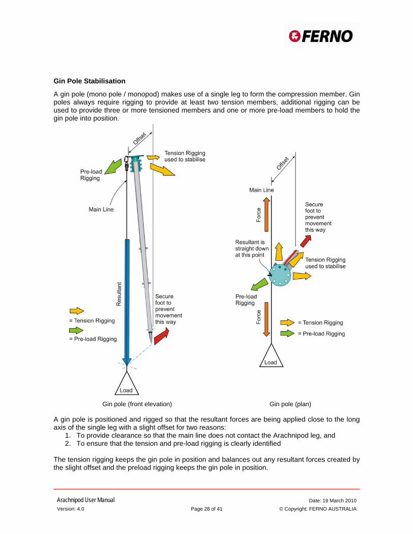
Gin Pole Stabilisation
A gin pole (mono pole / monopod) makes use of a single leg to form the compression member. Gin poles always require rigging to provide at least two tension members, additional rigging can be used to provide three or more tensioned members and one or more pre-load members to hold the gin pole into position.
Gin pole (front elevation) Gin pole (plan)
A gin pole is positioned and rigged so that the resultant forces are being applied close to the long axis of the single leg with a slight offset for two reasons:
1. To provide clearance so that the main line does not contact the Arachnipod leg, and 2. To ensure that the tension and pre-load rigging is clearly identified
The tension rigging keeps the gin pole in position and balances out any resultant forces created by the slight offset and the preload rigging keeps the gin pole in position.

Arachnipod User Manual Date: 19 March 2010 Version: 4.0 Page 29 of 41 © Copyright: FERNO AUSTRALIA
Using a single leg to manage a handrail
A single leg can be used to form a compression member that will help support a handrail. If the resultant direction is focused at a point that is just forward of the foot then most of the force will be transferred to the ground by the leg.
This technique is recommended for advanced users only; incorrect use of this system could be dangerous. An assessment of the handrail is required to ensure that it is suitable for this type of rigging. The angle of the leg and the resultant direction must be considered when assessing the handrail.
Leg securing ropes or round lashing can be used to provide tension rigging that keeps the single leg in place. Square lashing can be used to secure the leg to the hand rail.
Square lashing used here to secure the leg to the handrail
Additional rigging used to stabilise
Independent object used as the main line anchor
Arachnipod User Manual Date: 19 March 2010 Version: 4.0 Page 30 of 41 © Copyright: FERNO AUSTRALIA
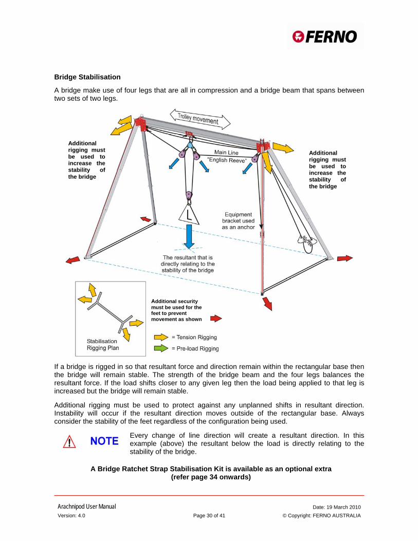
Bridge Stabilisation
A bridge make use of four legs that are all in compression and a bridge beam that spans between two sets of two legs.
If a bridge is rigged in so that resultant force and direction remain within the rectangular base then the bridge will remain stable. The strength of the bridge beam and the four legs balances the resultant force. If the load shifts closer to any given leg then the load being applied to that leg is increased but the bridge will remain stable. Additional rigging must be used to protect against any unplanned shifts in resultant direction. Instability will occur if the resultant direction moves outside of the rectangular base. Always consider the stability of the feet regardless of the configuration being used.
Every change of line direction will create a resultant direction. In this example (above) the resultant below the load is directly relating to the stability of the bridge.
A Bridge Ratchet Strap Stabilisation Kit is available as an optional extra (refer page 34 onwards)
Additional security must be used for the feet to prevent movement as shown
Additional rigging must be used to increase the stability of the bridge
Additional rigging must be used to increase the stability of the bridge
Arachnipod User Manual Date: 19 March 2010 Version: 4.0 Page 31 of 41 © Copyright: FERNO AUSTRALIA
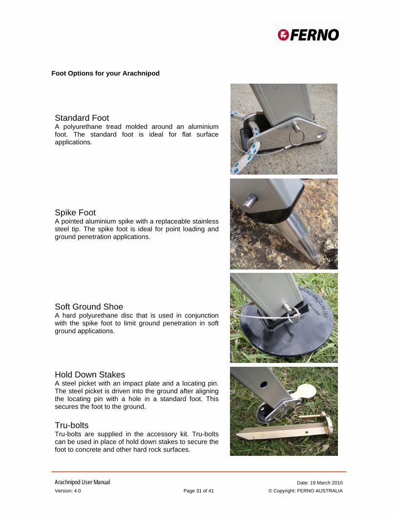
Foot Options for your Arachnipod
Standard Foot A polyurethane tread molded around an aluminium foot. The standard foot is ideal for flat surface applications.
Spike Foot A pointed aluminium spike with a replaceable stainless steel tip. The spike foot is ideal for point loading and ground penetration applications.
Soft Ground Shoe A hard polyurethane disc that is used in conjunction with the spike foot to limit ground penetration in soft ground applications.
Hold Down Stakes A steel picket with an impact plate and a locating pin. The steel picket is driven into the ground after aligning the locating pin with a hole in a standard foot. This secures the foot to the ground. Tru-bolts Tru-bolts are supplied in the accessory kit. Tru-bolts can be used in place of hold down stakes to secure the foot to concrete and other hard rock surfaces.
Arachnipod User Manual Date: 19 March 2010 Version: 4.0 Page 32 of 41 © Copyright: FERNO AUSTRALIA
General
The Arachnipod is used for securing persons that work in confined spaces where a fall from height may occur, specifically in areas such as tanks, shafts, trenches, mountain cliffs and voids or confined spaces that need entering. The use is limited to persons who are physically fit and have been instructed in the proper safe use of the product as well as obtaining the correct necessary knowledge in the use of the of the product. In order to rescue a person that has been involved in a fall or incident / accident a full emergency rescue plan must be implemented to consider all possible implications and situations that may occur during the rescue
Inspection of the Arachnipod
Equipment should be inspected regularly, before and after each use by a qualified person. Record the date of the inspection and the results in the equipment log. Each user should be trained in equipment inspection and should carry out an inspection before each use. Inspect the Arachnipod for cracks, dents, or elongation of the karabiner and pin holes. The legs should fit together smoothly and should not appear bent or deformed. Pins should have the retaining hardware present and must function freely. Inspect plastic parts for wear or chemical damage. If any significant damage is observed, the equipment should be removed from service. If there is any doubt regarding the safety of the equipment, it should be removed from service and retired.
Safety Information
If the Arachnipod has been subjected to impact or a fall, it is to be withdrawn from service immediately and must be tested and inspected by a suitably accredited qualified person or the supplier of the system, Please be aware that extreme temperature, chemicals and rough handling of the system may cause damage
Repairs
Any repair work must be done by the manufacturer or accredited agent. Any other repair work or modifications will void the warranty.
The Arachnipod has been engineered and tested using the original equipment as supplied. Never replace any pins, bolts or other components with non-genuine parts. Do not use your Arachnipod if any parts are missing.
For service or repairs, please contact your local Ferno Distributor
or Ferno Australia Phone: +61 7 3881 4999 Email: [email protected] www.ferno.com.au
Arachnipod User Manual Date: 19 March 2010 Version: 4.0 Page 33 of 41 © Copyright: FERNO AUSTRALIA
Care, Maintenance and Storage
Wash the unit with warm water and soft detergent soap, Rinse with clean water, Leave unpacked unit in a warm dry, well shaded and ventilated place to dry. Do not use additional heat sources or blowers to dry the unit. Avoid contact with chemical, oils, solvents and other aggressive corrosive materials or agents. Once cleaning is complete, Store unit in bag and store at room temperature away from direct sunlight. If unit requires any further maintenance contact your supplier for further details
Life Cycle
This is dependent on the individual operational conditions of each unit, The maximum lifespan of the unit is 12 years, however this would be dependent on many factors such as frequency of use, actual conditions of use, care and maintenance of the unit, weather and environmental conditions etc. The unit could be withdrawn from service before or after a specific use or on inspection during the mandatory annual review and therefore the lifespan of the unit is immediately terminated and must be removed from service immediately. Each unit has a date of manufacture on the individual components. Once the date of manufacture reaches 12 years, the unit must be removed from service and be destroyed accordingly.
Arachnipod User Manual Date: 19 March 2010 Version: 4.0 Page 34 of 41 © Copyright: FERNO AUSTRALIA
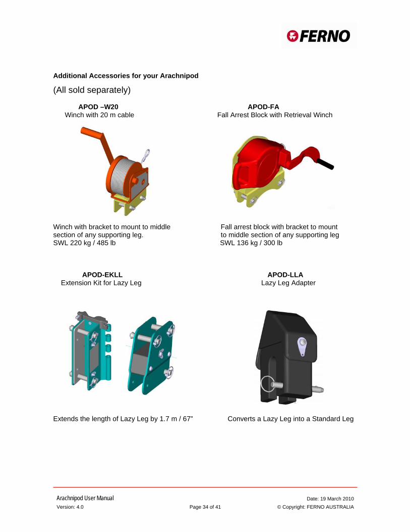
Additional Accessories for your Arachnipod
(All sold separately) APOD –W20 APOD-FA Winch with 20 m cable Fall Arrest Block with Retrieval Winch Winch with bracket to mount to middle Fall arrest block with bracket to mount section of any supporting leg. to middle section of any supporting leg SWL 220 kg / 485 lb SWL 136 kg / 300 lb APOD-EKLL APOD-LLA Extension Kit for Lazy Leg Lazy Leg Adapter Extends the length of Lazy Leg by 1.7 m / 67” Converts a Lazy Leg into a Standard Leg
Arachnipod User Manual Date: 19 March 2010 Version: 4.0 Page 35 of 41 © Copyright: FERNO AUSTRALIA
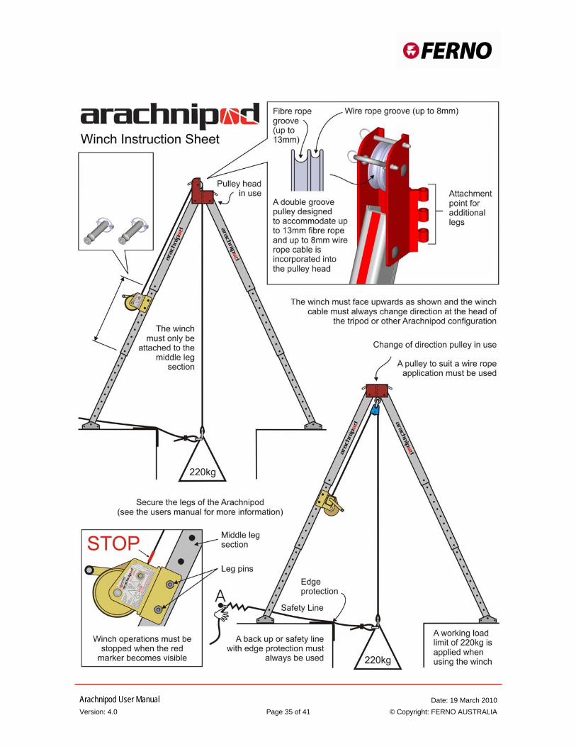
Attach the winch to the middle leg section with two leg pins secured with lynch pins
Arachnipod User Manual Date: 19 March 2010 Version: 4.0 Page 36 of 41 © Copyright: FERNO AUSTRALIA

Arachnipod User Manual Date: 19 March 2010 Version: 4.0 Page 37 of 41 © Copyright: FERNO AUSTRALIA
Arachnipod User Manual Date: 19 March 2010 Version: 4.0 Page 38 of 41 © Copyright: FERNO AUSTRALIA
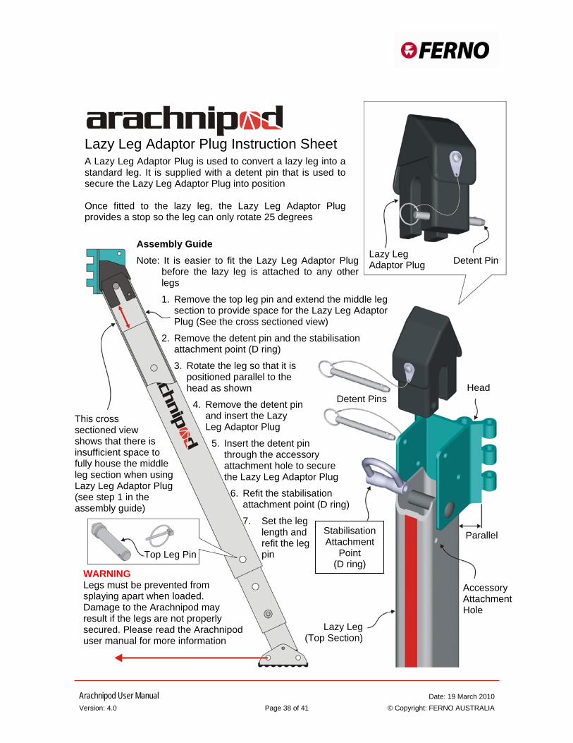
Assembly Guide Note: It is easier to fit the Lazy Leg Adaptor Plug
before the lazy leg is attached to any other legs
1. Remove the top leg pin and extend the middle leg section to provide space for the Lazy Leg Adaptor Plug (See the cross sectioned view)
2. Remove the detent pin and the stabilisation attachment point (D ring)
3. Rotate the leg so that it is positioned parallel to the head as shown
4. Remove the detent pin and insert the Lazy Leg Adaptor Plug
5. Insert the detent pin through the accessory attachment hole to secure the Lazy Leg Adaptor Plug
6. Refit the stabilisation attachment point (D ring)
7. Set the leg length and refit the leg pin
Lazy Leg Adaptor Plug Instruction Sheet A Lazy Leg Adaptor Plug is used to convert a lazy leg into a standard leg. It is supplied with a detent pin that is used to secure the Lazy Leg Adaptor Plug into position Once fitted to the lazy leg, the Lazy Leg Adaptor Plug provides a stop so the leg can only rotate 25 degrees
Lazy Leg Adaptor Plug Detent Pin
This cross sectioned view shows that there is insufficient space to fully house the middle leg section when using Lazy Leg Adaptor Plug (see step 1 in the assembly guide)
Top Leg Pin
WARNING Legs must be prevented from splaying apart when loaded. Damage to the Arachnipod may result if the legs are not properly secured. Please read the Arachnipod user manual for more information
Head Detent Pins
Parallel
Accessory Attachment Hole
Lazy Leg (Top Section)
Stabilisation Attachment
Point (D ring)

Arachnipod User Manual Date: 19 March 2010 Version: 4.0 Page 39 of 41 © Copyright: FERNO AUSTRALIA
Inspection and Maintenance Records
Record serial numbers and commission dates in the table below. Item
Serial number
Date commissioned into service
Tripod
Leg 1 AP-……….
Leg 2 AP-……….
Leg 3 AP-……….
Lazy Leg
AP-……….
Additional Leg
AP-……….
Bridge
AP-……….
Reverse Head
AP-……….
Fall Arrest Block
AP-……….
Winch
AP-……….
Lazy Leg Extender
Head assy AP-……….
Plate assy AP-……….
AP-……….
AP-……….
Arachnipods should be decommissioned from service after a maximum of 12 years from the date of commissioning into service, However if the date of commissioning into service is not recorded the unit should be decommissioned from service after 12 years from the date of manufacture,
Arachnipod User Manual Date: 19 March 2010 Version: 4.0 Page 40 of 41 © Copyright: FERNO AUSTRALIA
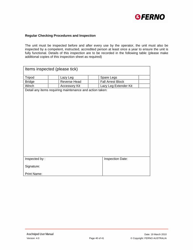
Regular Checking Procedures and Inspection
The unit must be inspected before and after every use by the operator, the unit must also be inspected by a competent, instructed, accredited person at least once a year to ensure the unit is fully functional. Details of this inspection are to be recorded in the following table: (please make additional copies of this inspection sheet as required) Items inspected (please tick) Tripod Lazy Leg Spare Legs Bridge Reverse Head Fall Arrest Block Winch Accessory Kit Lazy Leg Extender Kit Detail any items requiring maintenance and action taken:
Inspected by : Signature: Print Name:
Inspection Date:
Arachnipod User Manual Date: 19 March 2010 Version: 4.0 Page 41 of 41 © Copyright: FERNO AUSTRALIA
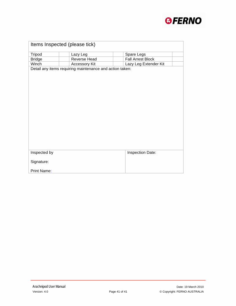
Items Inspected (please tick) Tripod Lazy Leg Spare Legs Bridge Reverse Head Fall Arrest Block Winch Accessory Kit Lazy Leg Extender Kit Detail any items requiring maintenance and action taken:
Inspected by Signature: Print Name:
Inspection Date:


![assets.hardwarezone.com · 2014-11-10 · On cash & notice. 118] ROSS Price updated as at 01,11.14 GHZ core IGA INiEL PROCESSOR 12 3MB 3MB 2MB 3MB 3MB 3MB 3MB 6MB 6MB 6MB 6MB 6MB](https://static.fdocuments.net/doc/165x107/5e7bac95fde25b33bb7faba0/2014-11-10-on-cash-notice-118-ross-price-updated-as-at-011114-ghz-core.jpg)

