User Interface Guide - Viconics · Temperature vs. Resistance Chart for 10 Kohm NTC Thermistor (R...
29
1 | 028-6112-00 January 2017 CONTENTS Terminal, Identification and Function 2 Screw terminal arrangement and wiring 2 Typical Applications 3 Main outputs wiring 3 Remote sensor accessories 4 Configuring and Status Display Instructions 5 Status display 5 User interface 7 User configuring instructions menu 7 Local keypad interface 7 Fresh Air Damper Control Sequences 25 Economizer Control Mode Only 25 Economizer Mode and Fresh Air Measurement Station 26 Economizer Mode and CO2 Level Control 27 Economizer Mode, CO2 Level Control and Fresh Air Measurement Station 28 VT7600E Series User Interface Guide January 10 th 2017 / 028-6112-00
Transcript of User Interface Guide - Viconics · Temperature vs. Resistance Chart for 10 Kohm NTC Thermistor (R...

1 | 028-6112-00 January 2017
CONTENTS Terminal, Identification and Function 2
Screw terminal arrangement and wiring 2 Typical Applications 3
Main outputs wiring 3 Remote sensor accessories 4
Configuring and Status Display Instructions 5 Status display 5
User interface 7 User configuring instructions menu 7 Local keypad interface 7
Fresh Air Damper Control Sequences 25 Economizer Control Mode Only 25 Economizer Mode and Fresh Air Measurement Station 26 Economizer Mode and CO2 Level Control 27 Economizer Mode, CO2 Level Control and Fresh Air Measurement Station 28
VT7600E Series
User Interface Guide
January 10 t h 2017 / 028-6112-00
2 | 028-6112-00 January 2017
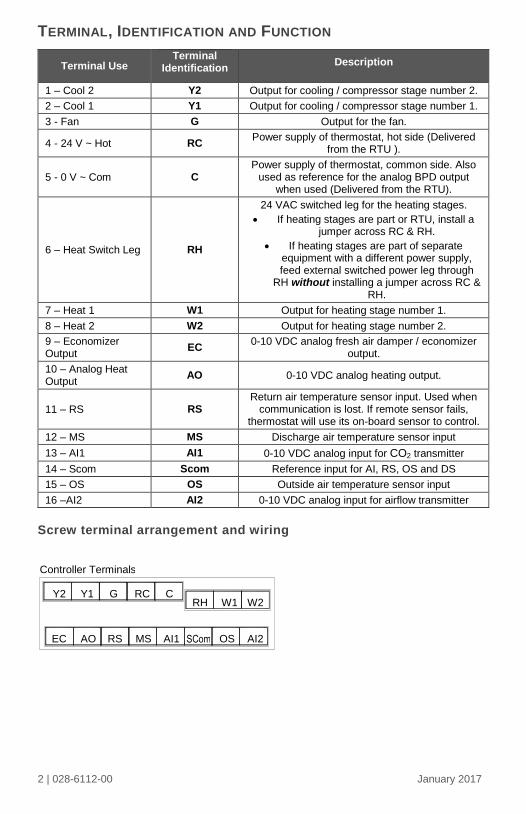
TERMINAL, IDENTIFICATION AND FUNCTION
Terminal Use Terminal
Identification Description
1 – Cool 2 Y2 Output for cooling / compressor stage number 2.
2 – Cool 1 Y1 Output for cooling / compressor stage number 1.
3 - Fan G Output for the fan.
4 - 24 V ~ Hot RC Power supply of thermostat, hot side (Delivered
from the RTU ).
5 - 0 V ~ Com C Power supply of thermostat, common side. Also
used as reference for the analog BPD output when used (Delivered from the RTU).
6 – Heat Switch Leg RH
24 VAC switched leg for the heating stages.
If heating stages are part or RTU, install a jumper across RC & RH.
If heating stages are part of separate equipment with a different power supply, feed external switched power leg through
RH without installing a jumper across RC & RH.
7 – Heat 1 W1 Output for heating stage number 1.
8 – Heat 2 W2 Output for heating stage number 2.
9 – Economizer Output
EC 0-10 VDC analog fresh air damper / economizer
output.
10 – Analog Heat Output
AO 0-10 VDC analog heating output.
11 – RS RS Return air temperature sensor input. Used when
communication is lost. If remote sensor fails, thermostat will use its on-board sensor to control.
12 – MS MS Discharge air temperature sensor input
13 – AI1 AI1 0-10 VDC analog input for CO2 transmitter
14 – Scom Scom Reference input for AI, RS, OS and DS
15 – OS OS Outside air temperature sensor input
16 –AI2 AI2 0-10 VDC analog input for airflow transmitter
Screw terminal arrangement and wiring
EC AO RS MS AI1 SCom OS AI2
G Y1 Y2 W2 W1 RH
C RC
Controller Terminals

3 | 028-6112-00 January 2017
TYPICAL APPLICATIONS
Main outputs wiring
Wiring notes:
Note 1: If the same power source is used for the heating stages, install jumper across RC &
RH. Maximum current is 2.0 amps.
Note 2: Economizer and all analog outputs and inputs use a half bridge rectifier. Reference
of the control signal is the common of the power supply of the Terminal Equipment
Controller. (Terminal C).
Note 3: Electromechanical contacts are to be used with the digital inputs. Electronic triacs
cannot be used as mean of switching for the input. The switched leg to the input for
the input to activate is terminal C (common)
Note 4: The transformer of the unit provides power to the t Terminal Equipment Controller
and the additional loads that will be wired to the Terminal Equipment Controller.

4 | 028-6112-00 January 2017
Remote sensor accessories
Model no. Description
S2020E1000 Outdoor temperature sensor
S2060A1000 Averaging temperature sensor
S2000D1000 Duct mounted temperature sensor
Remote mount temperature sensors use 10K NTC thermistor.
Temperature vs. Resistance Chart for 10 Kohm NTC Thermistor (R25°C = 10K±3% - B25/85°C = 3975K±1.5%)
S2000D1000; remote duct mounted temperature sensor c/w junction box. This sensor can be used for:
Remote return air temperature sensing with the sensor mounted on the return air duct.
Outside air temperature sensing with the sensor installed in the fresh air plenum.
Supply air temperature sensing. S2060A1000; remote averaging duct mounted temperature sensor c/w junction
box. This sensor can be used for:
Remote averaging return air temperature sensing with the sensor mounted on the return air duct.
Outside air temperature averaging sensing with the sensor installed in the fresh air plenum.
Supply air temperature averaging sensor for economizer models with the sensor in the mixing plenum.
ºC ºF Kohm ºC ºF Kohm ºC ºF Kohm ºC ºF Kohm ºC ºF Kohm
-40 -40 324.3197 -20 -4 94.5149 0 32 32.1910 20 68 12.4601 40 104 5.3467
-39 -38 303.6427 -19 -2 89.2521 1 34 30.6120 21 70 11.9177 41 106 5.1373
-38 -36 284.4189 -18 0 84.3147 2 36 29.1197 22 72 11.4018 42 108 4.9373
-37 -35 266.5373 -17 1 79.6808 3 37 27.7088 23 73 10.9112 43 109 4.7460
-36 -33 249.8958 -16 3 75.3299 4 39 26.3744 24 75 10.4443 44 111 4.5631
-35 -31 234.4009 -15 5 71.2430 5 41 25.1119 25 77 10.0000 45 113 4.3881
-34 -29 219.9666 -14 7 67.4028 6 43 23.9172 26 79 9.5754 46 115 4.2208
-33 -27 206.5140 -13 9 63.7928 7 45 22.7861 27 81 9.1711 47 117 4.0607
-32 -26 193.9703 -12 10 60.3980 8 46 21.7151 28 82 8.7860 48 118 3.9074
-31 -24 182.2686 -11 12 57.2044 9 48 20.7004 29 84 8.4190 49 120 3.7607
-30 -22 171.3474 -10 14 54.1988 10 50 19.7390 30 86 8.0694 50 122 3.6202
-29 -20 161.1499 -9 16 51.3692 11 52 18.8277 31 88 7.7360 51 124 3.4857
-28 -18 151.6239 -8 18 48.7042 12 54 17.9636 32 90 7.4182 52 126 3.3568
-27 -17 142.7211 -7 19 46.1933 13 55 17.1440 33 91 7.1150 53 127 3.2333
-26 -15 134.3971 -6 21 43.8268 14 57 16.3665 34 93 6.8259 54 129 3.1150
-25 -13 126.6109 -5 23 41.5956 15 59 15.6286 35 95 6.5499 55 131 3.0016
-24 -11 119.3244 -4 25 39.4921 16 61 14.9280 36 97 6.2866 56 133 2.8928
-23 -9 112.5028 -3 27 37.5056 17 63 14.2629 37 99 6.0351 57 135 2.7886
-22 -8 106.1135 -2 28 35.6316 18 64 13.6310 38 100 5.7950 58 136 2.6886
-21 -6 100.1268 -1 30 33.8622 19 66 13.0307 39 102 5.5657 59 138 2.5926
Fig.10 – Remote Duct Mounted Temperature Sensor

5 | 028-6112-00 January 2017
S2020E1000; outdoor air temperature sensor This sensor can be used for:
Outside air temperature sensing with the sensor installed directly exposed to the elements.
Sensor uses a water resistant NEMA 4 ABS enclosure for outdoor applications.
WIRING S2000D1000, S2060A1000 and S2020E1000
Remote wiring 1 sensor Remote wiring 4 sensors
CONFIGURING AND STATUS DISPLAY INSTRUCTIONS
Status display The Terminal Equipment Controller features a two-line, eight-character display. There is a
low backlight level that is always active and can only be seen at night.
When left unattended, the Terminal Equipment Controller has an auto scrolling display that
shows the current status of the system.
Each item is scrolled sequentially with the back lighting in low level mode. Pressing any key
will cause the back lighting to come on to high level.
Manual scrolling of each menu item is achieved by pressing the Yes (scroll) key repetitively.
The last item viewed will be shown on the display for 30 seconds before returning to
automatic scrolling. Temperature is automatically updated when scrolling is held.
Sequence of auto-scroll status display:
CLOCK
STATUS
SYSTEM
MODE
SCHEDULE
STATUS
OUTDOOR
TEMPERATURE ALARMS
Monday
12:00
AM
Sys
mode
auto
Occupied Outdoor
x.x °C or°F
Frost
ON
Sys
mode
off
Occupied
hold SetClock
Sys
mode
heat
Unoccup
DAS
alarm
Sys
mode
cool
FA
Alarm
10 K 10 K 10 K 10 K 10 K
Scom
DS
Scom
OS
Scom
RS or or
Scom
DS
Scom
OS
Scom
RS or or (
6 | 028-6112-00 January 2017
High
CO2
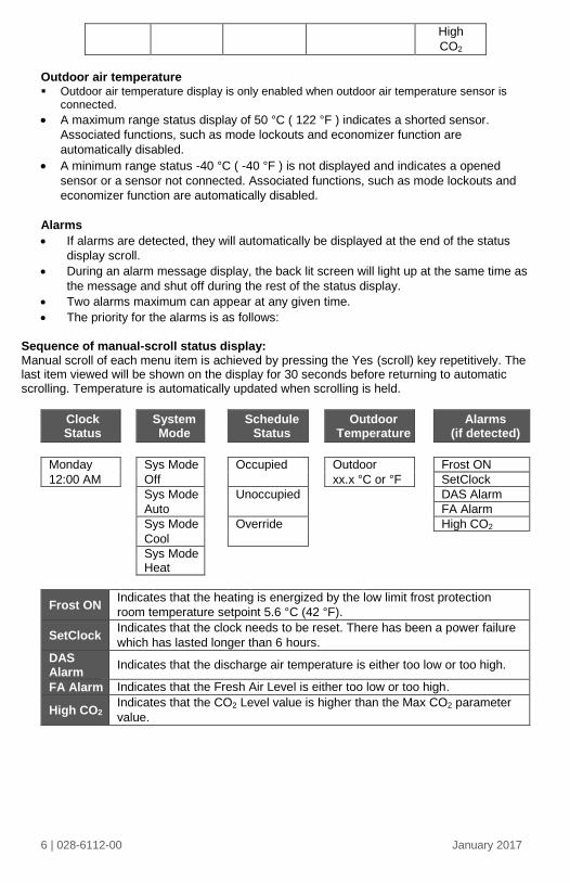
Outdoor air temperature Outdoor air temperature display is only enabled when outdoor air temperature sensor is
connected.
A maximum range status display of 50 °C ( 122 °F ) indicates a shorted sensor.
Associated functions, such as mode lockouts and economizer function are
automatically disabled.
A minimum range status -40 °C ( -40 °F ) is not displayed and indicates a opened
sensor or a sensor not connected. Associated functions, such as mode lockouts and
economizer function are automatically disabled.
Alarms
If alarms are detected, they will automatically be displayed at the end of the status
display scroll.
During an alarm message display, the back lit screen will light up at the same time as
the message and shut off during the rest of the status display.
Two alarms maximum can appear at any given time.
The priority for the alarms is as follows:
Sequence of manual-scroll status display: Manual scroll of each menu item is achieved by pressing the Yes (scroll) key repetitively. The last item viewed will be shown on the display for 30 seconds before returning to automatic scrolling. Temperature is automatically updated when scrolling is held.
Clock Status
System Mode
Schedule
Status
Outdoor Temperature
Alarms
(if detected)
Monday Sys Mode Occupied Outdoor Frost ON
12:00 AM Off xx.x °C or °F SetClock
Sys Mode Unoccupied DAS Alarm
Auto FA Alarm
Sys Mode Override High CO2
Cool
Sys Mode Heat
Frost ON Indicates that the heating is energized by the low limit frost protection
room temperature setpoint 5.6 °C (42 °F).
SetClock Indicates that the clock needs to be reset. There has been a power failure
which has lasted longer than 6 hours.
DAS Alarm
Indicates that the discharge air temperature is either too low or too high.
FA Alarm Indicates that the Fresh Air Level is either too low or too high.
High CO2 Indicates that the CO2 Level value is higher than the Max CO2 parameter
value.

7 | 028-6112-00 January 2017
USER INTERFACE
When any of the fan is ON, the FAN LED will illuminate
When heating is ON, the HEAT LED will illuminate
When cooling is ON, the COOL LED will illuminate
User configuring instructions menu
The VT76X6E series of controllers feature an intuitive, menu-driven, back-lit LCD display that walks users and installers through the configuring steps, making the configuring process extremely simple. This menu is typically accessed by the user to set the parameters such as the clock time set, the schedule time events and the system mode. It is possible to bring up the user menu at any time by depressing the MENU key. The status display automatically resumes after exiting the user-configuring menu. If the user pauses at any given time during configuring, Auto Help text is displayed to help and guide the user through the usage and configuring of the controller.
Ex.: Press yes key to change cooling temperature setpoint
Use the up or down arrow to adjust cooling setpoint
Each of the sections in the menu is accessed and configured using 5 keys on the
controller cover. The priority for the alarms is as follows:
Local keypad interface
The YES key is used to confirm a selection, to move onto the next menu item
and to manually scroll through the displayed information.
The NO key is used when you do not desire a parameter change, and to
advance to the next menu item. Can also be used to toggle between heating
and cooling setpoints.
The MENU key is used to access the Main User Menu or exit the menu.
The down arrow key is used to decrease temperature setpoint and to adjust
the desired values when configuring the Terminal Equipment Controller.
The up arrow key is used to increase temperature setpoint and to adjust the
desired values when configuring the Terminal Equipment Controller.
8 | 028-6112-00 January 2017
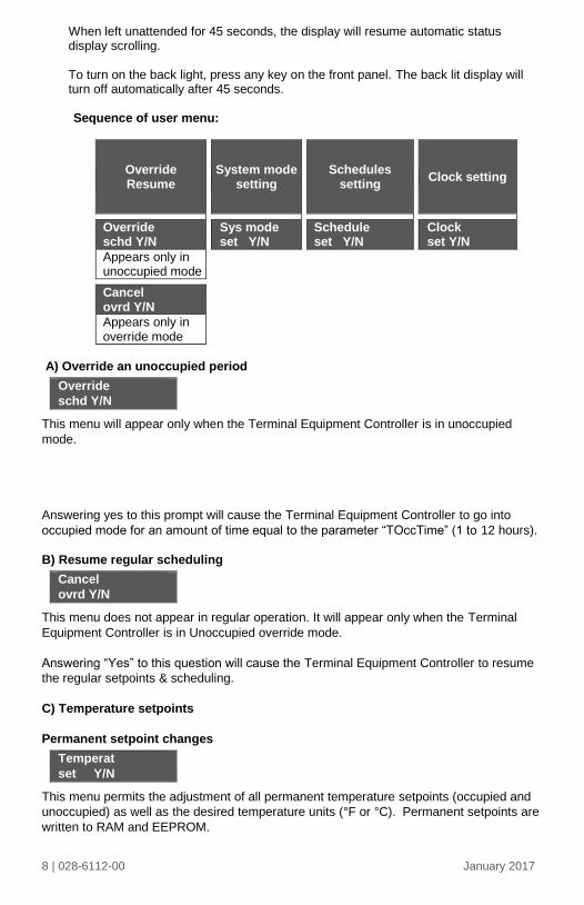
When left unattended for 45 seconds, the display will resume automatic status display scrolling. To turn on the back light, press any key on the front panel. The back lit display will turn off automatically after 45 seconds. Sequence of user menu:
Override Resume
System mode
setting
Schedules setting
Clock setting
Override schd Y/N
Sys mode set Y/N
Schedule set Y/N
Clock set Y/N
Appears only in unoccupied mode
Cancel ovrd Y/N
Appears only in override mode
A) Override an unoccupied period
Override
schd Y/N
This menu will appear only when the Terminal Equipment Controller is in unoccupied
mode.
Answering yes to this prompt will cause the Terminal Equipment Controller to go into
occupied mode for an amount of time equal to the parameter “TOccTime” (1 to 12 hours).
B) Resume regular scheduling
Cancel
ovrd Y/N
This menu does not appear in regular operation. It will appear only when the Terminal
Equipment Controller is in Unoccupied override mode.
Answering “Yes” to this question will cause the Terminal Equipment Controller to resume
the regular setpoints & scheduling.
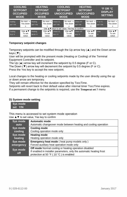
C) Temperature setpoints
Permanent setpoint changes
Temperat
set Y/N
This menu permits the adjustment of all permanent temperature setpoints (occupied and
unoccupied) as well as the desired temperature units (°F or °C). Permanent setpoints are
written to RAM and EEPROM.
9 | 028-6112-00 January 2017
COOLING
SETPOINT
OCCUPIED
MODE
HEATING
SETPOINT
OCCUPIED
MODE
COOLING
SETPOINT
UNOCCUPIED
MODE
HEATING
SETPOINT
UNOCCUPIED
MODE
°F OR °C
DISPLAY
SETTING
Cooling
set? Y/N
No next
Yes down
Heating
set? Y/N
No next
Yes down
Unocc CL
set? Y/N
No next
Yes down
Unocc HT
set? Y/N
No next
Yes down
°F or °C
set? Y/N
No next
Yes down
Use ▲▼ keys to set value, Yes key to confirm
Cooling
70.0 °F
Use ▲▼
To set
value
Heating
68.00 °F
Use ▲▼
To set
value
Unocc CL
80.0 °F
Use ▲▼
To set
value
Unocc HT
60.0 °F
Use ▲▼
To set
value
Units
°F
Use ▲▼
To set
value
Temporary setpoint changes
Temporary setpoints can be modified through the Up arrow key (▲) and the Down arrow
keys (▼).
User will be prompted with the present mode (Heating or Cooling) of the Terminal
Equipment Controller and its setpoint.
The Up (▲) arrow key will increment the setpoint by 0.5 degree (F or C).
The Down (▼) arrow key will decrement the setpoint by 0.5 degree (F or C).
Press the Yes key to accept the new setpoint.
Local changes to the heating or cooling setpoints made by the user directly using the up
or down arrow are temporary.
They will remain effective for the duration specified by ToccTime.
Setpoints will revert back to their default value after internal timer ToccTime expires.
If a permanent change to the setpoints is required, use the Temperat set ? menu
D) System mode setting
Sys mode
set Y/N
This menu is accessed to set system mode operation Use ▲▼ to set value, Yes key to confirm
Sys mode
auto
Automatic mode
Automatic changeover mode between heating and cooling operation
Sys mode
cooling
Cooling mode
Cooling operation mode only
Sys mode
heating
Heating mode
Heating operation mode only
Sys mode
emergency
Emergency heat mode ( heat pump models only )
Forced auxiliary heat operation mode only
Sys mode
off
Off mode Normal cooling or heating operation disabled
If enabled in installer parameters, only the automatic heating frost
protection at 50 °F ( 10 °C ) is enabled
10 | 028-6112-00 January 2017
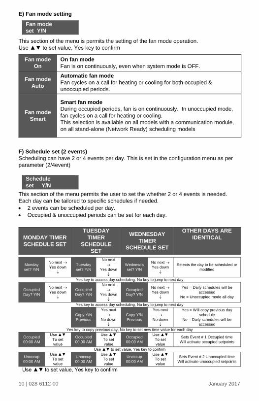
E) Fan mode setting
Fan mode
set Y/N
This section of the menu is permits the setting of the fan mode operation.
Use ▲▼ to set value, Yes key to confirm
Fan mode
On
On fan mode
Fan is on continuously, even when system mode is OFF.
Fan mode
Auto
Automatic fan mode
Fan cycles on a call for heating or cooling for both occupied &
unoccupied periods.
Fan mode
Smart
Smart fan mode
During occupied periods, fan is on continuously. In unoccupied mode,
fan cycles on a call for heating or cooling.
This selection is available on all models with a communication module,
on all stand-alone (Network Ready) scheduling models
F) Schedule set (2 events)
Scheduling can have 2 or 4 events per day. This is set in the configuration menu as per
parameter (2/4event)
Schedule
set Y/N
This section of the menu permits the user to set the whether 2 or 4 events is needed.
Each day can be tailored to specific schedules if needed.
2 events can be scheduled per day.
Occupied & unoccupied periods can be set for each day.
MONDAY TIMER
SCHEDULE SET
TUESDAY
TIMER
SCHEDULE
SET
WEDNESDAY
TIMER
SCHEDULE SET
OTHER DAYS ARE
IDENTICAL
Monday
set? Y/N
No next
Yes down
Tuesday
set? Y/N
No next
Yes down
Wednesda
set? Y/N
No next
Yes down
Selects the day to be scheduled or
modified
Yes key to access day scheduling, No key to jump to next day
Occupied
Day? Y/N
No next
Yes down
Occupied
Day? Y/N
No next
Yes down
Occupied
Day? Y/N
No next
Yes down
Yes = Daily schedules will be
accessed
No = Unoccupied mode all day
Yes key to access day scheduling, No key to jump to next day
Copy Y/N
Previous
Yes next
No down
Copy Y/N
Previous
Yes next
No down
Yes = Will copy previous day
schedule
No = Daily schedules will be
accessed
Yes key to copy previous day, No key to set new time value for each day
Occupied
00:00 AM
Use ▲▼
To set
value
Occupied
00:00 AM
Use ▲▼
To set
value
Occupied
00:00 AM
Use ▲▼
To set
value
Sets Event # 1 Occupied time
Will activate occupied setpoints
Use ▲▼ to set value, Yes key to confirm
Unoccup
00:00 AM
Use ▲▼
To set
value
Unoccup
00:00 AM
Use ▲▼
To set
value
Unoccup
00:00 AM
Use ▲▼
To set
value
Sets Event # 2 Unoccupied time
Will activate unoccupied setpoints
Use ▲▼ to set value, Yes key to confirm

11 | 028-6112-00 January 2017
Typical examples of a 2 event office schedule:
Ex. #1 Office building closed all weekend
Event Period #1 - Event #1 Period #1 - Event #2
Occupied Unoccupied
Setpoint Cool Heat Cool Heat Daily
72 °F 70 °F 80 °F 62 °F Occupancy
Monday 7.00 AM 6.00 PM Day time only
Tuesday 7.00 AM 6.00 PM Day time only
Wednesday 7.00 AM 6.00 PM Day time only
Thursday 7.00 AM 6.00 PM Day time only
Friday 7.00 AM 6.00 PM Day time only
Saturday 12.00 PM * 12.00 PM * Unoccupied
Sunday 12.00 PM * 12.00 PM * Unoccupied
* Scheduling consecutive events to the same time will cause the Terminal Equipment
Controller to choose the last event as the time at which it will set its schedule. In the
above example, the Terminal Equipment Controller will control to the unoccupied set
point until 7:00 AM Monday.
Ex. #2 Commercial building which is occupied all weekend
Event Period #1 - Event
#1
Period #1 - Event
#2
Occupied Unoccupied
Setpoint Cool Heat Cool Heat Daily
72 °F 70 °F 80 °F 62 °F Occupancy
Monday 8.00 AM 5.00 PM Day time only
Tuesday 8.00 AM 5.00 PM Day time only
Wednesday 8.00 AM 5.00 PM Day time only
Thursday 8.00 AM 5.00 PM Day time only
Friday 8.00 AM 5.00 PM Day time only
Saturday 12.00 AM ** 11.59 PM ** Occupied
Sunday 12.00 AM ** 11.59 PM ** Occupied
** To schedule a day as occupied for 24 hours, set that day occupied time to 12:00 AM
and Unoccupied time to 11:59 PM There will be a 1 minute unoccupied period every
night at 11:59 PM with this schedule configuration.
Note: 12:00 PM = Noon 12:00 AM = Midnight

12 | 028-6112-00 January 2017
G) Schedule set (4 events)
Schedule
set Y/N
This section of the menu permits the user to set the whether 2 or 4 events is needed. Each
day can be tailored to specific schedules if needed.
4 events can be scheduled per day.
Occupied & Unoccupied periods can be set for each day.
Scheduling the 3rd. & 4th. Events to the same time will cancel the last period.
Monday timer
Schedule set
Tuesday timer
Schedule set
Wednesday timer
Schedule set Other days are identical
Monday
set? Y/N
No next
Yes down
Tuesday
set? Y/N
No next
Yes down
Wednesda
set? Y/N
No next
Yes down
Selects the day to be scheduled
or modified
Yes key to access day scheduling, No key to jump to next day
Occupied
Day? Y/N
No next
Yes down
Occupied
Day? Y/N
No next
Yes down
Occupied
Day? Y/N
No next
Yes down
Yes = Daily schedules will be
accessed
No = Unoccupied mode all day
Yes key to access day scheduling, No key to jump to next day
Copy Y/N
Previous
Yes next
No down
Copy Y/N
Previous
Yes next
No down
Yes = Will copy previous day
schedule
No = Daily schedules will be
accessed
Yes key to copy previous day, No key to set new time value for each day
Occupied
00:00 AM
Use ▲▼
To set
value
Occupied
00:00 AM
Use ▲▼
To set
value
Occupied
00:00 AM
Use ▲▼
To set
value
Sets Event # 1 Occupied time
Will activate occupied
setpoints
Use ▲▼ to set value, Yes key to confirm
Unoccup
00:00 AM
Use ▲▼
To set
value
Unoccup
00:00 AM
Use ▲▼
To set
value
Unoccup
00:00 AM
Use ▲▼
To set
value
Sets Event # 2 Unoccupied
time
Will activate unoccupied
setpoints
Use ▲▼ to set value, Yes key to confirm
Occupie2
00:00 AM
Use ▲▼
To set
value
Occupie2
00:00 AM
Use ▲▼
To set
value
Occupie2
00:00 AM
Use ▲▼
To set
value
Sets Event # 3 Occupied time
Will activate occupied
setpoints
Use ▲▼ to set value, Yes key to confirm
Unoccup2
00:00 AM
Use ▲▼
To set
value
Unoccup2
00:00 AM
Use ▲▼
To set
value
Unoccup2
00:00 AM
Use ▲▼
To set
value
Sets Event # 4 Unoccupied
time
Will activate unoccupied
setpoints
Use ▲▼ to set value, Yes key to confirm

13 | 028-6112-00 January 2017
Ex. #1 Four event retail establishment schedule
Event Period 1 -
Event 1
Period 1 -
Event 2
Period 2 -
Event 3
Period 2 -
Event 4
Setpoint Occupied Unoccupied Occupied Unoccupied
Cool Heat Cool Heat Cool Heat Cool Heat Daily
72°F 70°F 80°F 62°F 72°F 70
°F 80°F
62
°F Occupancy
Monday 7.00 AM 5.00 PM 12.00 PM * 12.00 PM * Day time
only
Tuesday 7.00 AM 5.00 PM 12.00 PM * 12.00 PM * Day time
only
Wednesday 7.00 AM 5.00 PM 12.00 PM * 12.00 PM * Day time
only
Thursday 7.00 AM 5.00 PM 7.00 PM 10.30 PM Day/evening
time only
Friday 7.00 AM 5.00 PM 7.00 PM 10.30 PM Day/evening
time only
Saturday 12.00 PM * 12.00 PM * 12.00 PM * 12.00 PM * Unoccupied
Sunday 12.00 PM * 12.00 PM * 12.00 PM * 12.00 PM * Unoccupied
* Scheduling events to the same time will cancel the last period and leave the Terminal
Equipment Controller in unoccupied mode
Ex. #2 Residential
Event Period 1 -
Event 1
Period 1 -
Event 2
Period 2 -
Event 3
Period 2 -
Event 4
Setpoint Occupied Unoccupied Occupied Unoccupied
Cool Heat Cool Heat Cool Heat Cool Heat Daily
72°F 70°F 80°F 62°F 72°F 70°F 80°F 62°F Occupancy
Monday 6:00 AM 8:00 AM 4:00 PM 10:00 PM Day/evening
time only
Tuesday 6:00 AM 8:00 AM 4:00 PM 10:00 PM Day/evening
time only
Wednesday 6:00 AM 8:00 AM 4:00 PM 10:00 PM Day/evening
time only
Thursday 6:00 AM 8:00 AM 4:00 PM 10:00 PM Day/evening
time only
Friday 6:00 AM 8:00 AM 4:00 PM 11:30 PM Day/evening
time only
Saturday 8:00 AM * 8:00 AM * 8:00 AM * 11:59 PM * Day time
only
Sunday 12:00 AM * 12:00 AM * 12:00 AM * 11:59 PM * Occupied all
day
* Scheduling consecutive events to the same time will cause the Terminal Equipment
Controller to choose the last event as the time at which it will set its schedule. In the above
example for Saturday, the Terminal Equipment Controller will control to the occupied set
point from 8:00 AM until 11:59 PM. Since it is desired to be in occupied mode throughout
the night, then it is necessary to schedule the first event on Sunday at 12:00 AM. The
Terminal Equipment Controller will force a one minute unoccupied period for a one minute
period (between 11:59 PM and 12:00 AM on Saturday).

14 | 028-6112-00 January 2017
H) Clock/Day Settings
Clock
set Y/N
This section of the menu permits the user to set the time and day.
Time setting Day setting Time format setting
Time
set? Y/N
No next
Yes down
Day
set? Y/N
No next
Yes down
12/24hrs
set? Y/N
No = exit
Yes down
Time
0:00
Use ▲▼
To set value
Day
Monday
Use ▲▼
To set value
12/24hrs
12 hrs
Use ▲▼
To set value
J) Schedule hold
Schedule
hold Y/N
This menu will only appear on stand-alone (Network Ready) Terminal
Equipment Controller, i.e. without a BACnet™ / Echelon™ module.
This section of the menu permits the user to set a permanent schedule
hold, which bypasses the internal Terminal Equipment Controller
scheduling.
The permanent schedule hold function is typically used for non-
scheduled events that extend for various periods of time.
Enabling a permanent occupied or permanent unoccupied schedule hold
will cancel any active override.
The use of temporary setpoints during permanent hold is permitted. The
duration of the temporary setpoint is as set per the TOccTime parameter.
Ex. 3 hours
Use ▲▼ to set value, yes key to confirm

15 | 028-6112-00 January 2017
CONFIGURATION
PARAMETERS
DEFAULT VALUE
SIGNIFICANCE AND ADJUSTMENTS
PswrdSet
Configuration parameters
menu access password
Default value = 0
No password prompted
This parameter sets a password access to prevent
unauthorized access to the configuration menu
parameters. A default value of “0” will not prompt a
password or lock the access to the configuration
menu.
Range is: 0 to 1000
Com addr Thermostat networking address
Default value = 254
Range is: 0 to 254
Conditional parameter to BACnet MS-TP models (VT76xxX5x00B)
Conditional parameter to Wireless models (VT76xxX5x00W)
This parameter will only appear when a BACnet or wireless network adapter is present. If the thermostat is installed as a stand-alone unit or with an Echelon adapter, this parameter will not be used or displayed
- For BACnet MS-TP models valid range to use is from 1 to 127. Default value of 254 disables BACnet communication for the thermostat.
- For wireless models valid range is 0 to 254 with a
maximum of 30 thermostat per VWG
PAN ID
Personal Area Network
Identification
Default value = 0
Range is: 0 to 1000
Conditional parameter to Wireless models
(VT76xxX5x00W)
This parameter will only appear when a wireless
network adapter is present. If the Terminal
Equipment Controller is installed as a stand-alone
(Network Ready) unit or with a BACnet™ or
Echelon™ adapter, this parameter will not be used or
displayed
This parameter (Personal Area Network
Identification) is used to link specific Terminal
Equipment Controllers to a single specific Viconics
wireless gateway ( VWG ) For every Terminal
Equipment Controller reporting to a gateway
( maximum of 30 Terminal Equipment Controllers per
gateway ), be sure you set the SAME PAN ID value
both at the gateway and the Terminal Equipment
Controller(s).
The default value of 0 is NOT a valid PAN ID.

16 | 028-6112-00 January 2017
Channel
Channel selection
Default value = 10
Range is: 10 to 26
Conditional parameter to Wireless models
(VT76xxX5x00W)
This parameter will only appear when a wireless
network adapter is present. If the Terminal Equipment
Controller is installed as a stand-alone (Network
Ready) unit or with a BACnet™ or Echelon™ adapter,
this parameter will not be used or displayed
This parameter (Channel) is used to link specific
Terminal Equipment Controllers to specific Viconics
wireless gateway(s) (VWG) For every Terminal
Equipment Controller reporting to a gateway
(maximum of 30 Terminal Equipment Controllers per
gateway), be sure you set the SAME channel value
both at the gateway and the Terminal Equipment
Controller(s).
Viconics recommends using only the usage of
channels 15 and 25 only.
The default value of 10 is NOT a valid channel. The
valid range of available channel is from 11 to 26
AI1
Analog input no.1 configuration
Default value = None
None, No function will be associated with the input
CO2, the 0-10VDC input value is used as a 0-2000ppm
CO2 level:
0 VDC = 0ppm
10VDC = 2000ppm
FA Range
FA range upper limit value
Default value = 0 CFM
Sets the upper limit of the CFM range. This parameter
should be set based on the rooftop unit size. If set to 0
CFM, the fresh air damper control will be based on the
Min/Max CO2 and Min/Max Pos values. See Damper
Position section for more details.
0 to 20 000 CFM (0 to 9438 L/s), 10 or 100 increments
MenuScro
Menu scroll
Default value = On = Scroll
active
Removes the scrolling display and only present the room temperature/humidity to the user. With this option enabled, no status is given of mode, schedule and outdoor temperature.
On = Scroll active
Off = Scroll not active
Lockout Keypad lockout levels
Default value = 0 No lock
0 = No lock
1 = Low level
2 = High level

17 | 028-6112-00 January 2017
USER KEY FUNCTIONS
LE
VE
L
Re
su
me/
Ov
err
ide
sc
he
du
lin
g
Pe
rma
ne
nt
Oc
cu
pie
d a
nd
Un
oc
cu
pie
d S
etp
oin
ts
Te
mp
ora
ry s
etp
oin
ts u
sin
g
arr
ow
s
Sy
ste
m m
od
e s
ett
ing
Fa
n m
od
e s
ett
ing
Sc
he
du
les
sett
ing
Clo
ck
se
ttin
g
Pe
rma
ne
nt
ho
ld
0 1 2
pwr del
Power-up delay
Default value = 10 seconds
On initial power up of the Terminal Equipment Controller
(each time 24 VAC power supply is removed & re-applied)
there is a delay before any operation is authorized (fan,
cooling or heating). This can be used to sequence start up
multiple units / Terminal Equipment Controller in one
location.
10 to 120 seconds
Frost pr
Frost protection enabled
Default value = Off
Off: no room frost protection
On: room frost protection enabled in all system mode at:
42 °F ( 5.6 °C )
Frost protection is enabled even in system Off mode
Off or On
On heat pump models the system mode will be forced to
EMERGENCY mode if frost protection is activated
heat max
Maximum heating setpoint
limit
Default value = 90 °F (32 °C )
Maximum occupied & unoccupied heating setpoint
adjustment. Heating setpoint range is:
40 to 90 °F ( 4.5 to 32.0 °C )
cool min
Minimum cooling setpoint
limit
Default value = 54 °F ( 2 °C )
Minimum occupied & unoccupied cooling setpoint
adjustment. Cooling setpoint range is:
54 to 100 °F ( 12.0 to 37.5 °C )
18 | 028-6112-00 January 2017
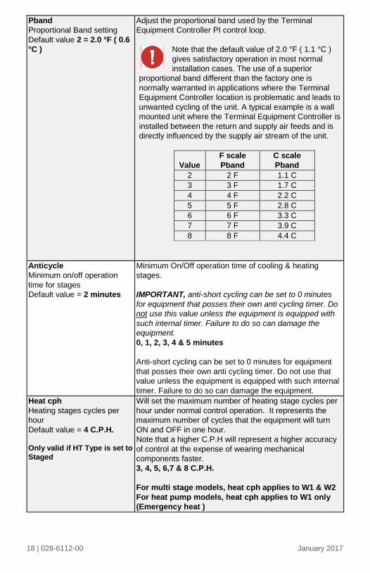
Pband
Proportional Band setting
Default value 2 = 2.0 °F ( 0.6
°C )
Adjust the proportional band used by the Terminal
Equipment Controller PI control loop.
Note that the default value of 2.0 °F ( 1.1 °C )
gives satisfactory operation in most normal
installation cases. The use of a superior
proportional band different than the factory one is
normally warranted in applications where the Terminal
Equipment Controller location is problematic and leads to
unwanted cycling of the unit. A typical example is a wall
mounted unit where the Terminal Equipment Controller is
installed between the return and supply air feeds and is
directly influenced by the supply air stream of the unit.
Value
F scale
Pband
C scale
Pband
2 2 F 1.1 C
3 3 F 1.7 C
4 4 F 2.2 C
5 5 F 2.8 C
6 6 F 3.3 C
7 7 F 3.9 C
8 8 F 4.4 C
Anticycle
Minimum on/off operation
time for stages
Default value = 2 minutes
Minimum On/Off operation time of cooling & heating
stages.
IMPORTANT, anti-short cycling can be set to 0 minutes
for equipment that posses their own anti cycling timer. Do
not use this value unless the equipment is equipped with
such internal timer. Failure to do so can damage the
equipment.
0, 1, 2, 3, 4 & 5 minutes
Anti-short cycling can be set to 0 minutes for equipment
that posses their own anti cycling timer. Do not use that
value unless the equipment is equipped with such internal
timer. Failure to do so can damage the equipment.
Heat cph
Heating stages cycles per
hour
Default value = 4 C.P.H.
Only valid if HT Type is set to
Staged
Will set the maximum number of heating stage cycles per
hour under normal control operation. It represents the
maximum number of cycles that the equipment will turn
ON and OFF in one hour.
Note that a higher C.P.H will represent a higher accuracy
of control at the expense of wearing mechanical
components faster.
3, 4, 5, 6,7 & 8 C.P.H.
For multi stage models, heat cph applies to W1 & W2
For heat pump models, heat cph applies to W1 only
(Emergency heat )

19 | 028-6112-00 January 2017
cool cph
Cooling stages cycles per hour
Default value = 4 C.P.H.
Will set the maximum number of cooling stage cycles per
hour under normal control operation. It represents the
maximum number of cycles that the equipment will turned
on and off in one hour.
Note that a higher C.P.H will represent a higher accuracy
of control at the expense of wearing mechanical
components faster.
3 or 4 C.P.H.
For multi stage models, cool cph applies to Y1 & Y2
For heat pump models, cool cph applies to Y1 & Y2 in
cooling and heating independently of the reversing
valve position
deadband
Minimum deadband
Default value = 2.0 °F (1.1 °C)
Minimum deadband value between the heating and
cooling setpoints. If modified, it will be applied only
when any of the setpoints are modified.
2, 3 or 4 °F ( 1.0 to 2.0 °C )
fan cont
Fan control
Default value = On
Fan control in heating mode.
When selecting On; the Terminal Equipment Controller
in all cases will always control the fan (terminal G).
Valid for On or Auto fan mode
When selecting Off; the fan (terminal G), when heating
stages (terminals W1 & W2) are solicited, will not be
energized. The fan in this case will be controlled by the
equipment fan limit control.
Valid only for Auto fan mode. On fan mode will leave
the fan always on.
ON OR OFF
For multi stage models, fan control applies to W1 &
W2
For heat pump models, fan control applies to W1
only (Emergency heat)
fan del
Fan delay
Default value = Off
Fan delay extends fan operation by 60 seconds after
the call for heating or cooling ends.
Valid only for Auto fan mode. “On” fan mode will leave
the fan always on.
Off or On
ToccTime
Temporary occupancy time
Default value = 3 hours
Temporary occupancy time with occupied mode
setpoints when override function is enabled
When the Terminal Equipment Controller is in
unoccupied mode, function is enabled with the menu.
0,1, 2, 3, 4, 5, 6, 7, 8, 9, 10, 11 & 12 hours
Cal RS
Room air temperature sensor
calibration
Default value = 0.0 °F or °C
Offset that can be added/subtracted to actual displayed
room temperature
± 5.0 °F ( ± 2.5 °C )

20 | 028-6112-00 January 2017
Cal OS
Outside air temperature sensor
calibration
Default value = 0.0 °F or °C
Offset that can be added/subtracted to actual displayed
outside air temperature
± 5.0 °F ( ± 2.5 °C )
H stage
Number of heating stages.
Default value = 2 stages
Will revert the operation of 2 stages thermostat to
single stage operation or to modulating 0 to 10Vdc
heating output:
0 = 0-10Vdc analog heating output (AO)
1 = 1 heating stage (W1)
2 = 2 heating stages (W1 & W2)
C stage
Number of cooling stages
Default value = 2 stages
Will revert the operation of 2 stage Terminal Equipment
Controller to single stage operation only when the
second cooling step is not needed.
1 or 2 stages
H lock
Outside air temperature heating
lockout
Default value = 120 °F ( 49 °C )
Disables heating stage operation based on outdoor air
temperature.
Function will only be enabled if OS (outside air
temperature sensor) is connected.
From -15 °F up to 120 °F ( -26 °C up to 49 °C )
C lock
Outside air temperature
mechanical cooling lockout.
Default value = -40 °F ( -40 °C )
Disables cooling stage operation based on outdoor air
temperature.
On economizer model, free cooling will not be disabled
by this function.
Function will only be enabled if OS (outside air
temperature sensor) is connected.
From -40 °F up to 95 °F ( -40 °C up to 35 °C )
Unocc TM
Unoccupied Timer value
Default 0.5 hours
Time delay between the moment where the Terminal
Equipment Controller toggles from occupied to
unoccupied after the last movement has been detected
by the PIR.
Range is: 0.5 to 24.0 hours in 0.5 hour increments

21 | 028-6112-00 January 2017
2/4event
Number of events configuration
Default value = 2 event
2 events, will set up scheduling for the following
Event 1 is for Occupied setpoints
Event 2 is for Unoccupied setpoints
4 events, will set up scheduling for the following
Event 1 is for Occupied setpoints
Event 2 is for Unoccupied setpoints
Event 3 is for Occupied setpoints
Event 4 is for Unoccupied setpoints
Prog rec
Progressive recovery enabled
Default value = Off
Progressive recovery is
automatically disabled if DI 1
and / or DI 2 are configured
remote NSB
Off, = no progressive recovery
The occupied schedule time is the time at which the
system will restart.
On, = progressive recovery active.
The occupied schedule time is the time at which the
desired occupied temperature will be attained. The
Terminal Equipment Controller will automatically optimize
the equipment start time.
In any case, the latest a system will restart is 10 minutes
prior to the occupied period time.
Min SH
Only valid if HT Type is set to
Analog
Minimum supply heat
temperature setpoint
Default value = 64 °F (18 °C)
Sets the minimum supply heat to be maintained by the
controller during occupied periods (Occupied or
Temporary Override).
From 50 °F up to 72 °F (10 °C up to 22 °C)
(increments: 0.5° or 5°)
Chngstpt
Changeover setpoint
Default value = 55 °F ( 13.0 °C )
In Cooling mode.
The outside air temperature value at which the cooling will be switched over from mechanical ( compressor ) to free cooling ( economizer )
14 to 70 °F ( -10.0 to 21.0 °C )
22 | 028-6112-00 January 2017
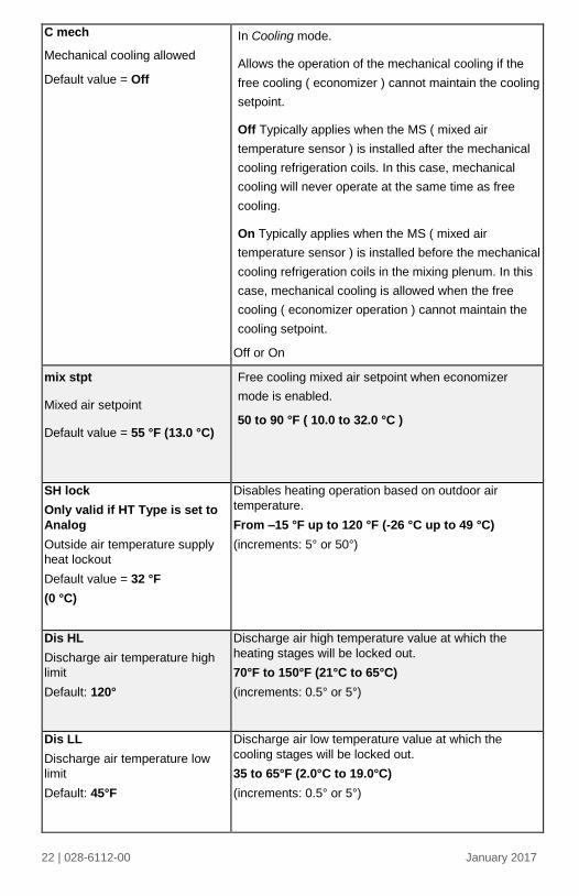
C mech
Mechanical cooling allowed
Default value = Off
In Cooling mode.
Allows the operation of the mechanical cooling if the
free cooling ( economizer ) cannot maintain the cooling
setpoint.
Off Typically applies when the MS ( mixed air
temperature sensor ) is installed after the mechanical
cooling refrigeration coils. In this case, mechanical
cooling will never operate at the same time as free
cooling.
On Typically applies when the MS ( mixed air
temperature sensor ) is installed before the mechanical
cooling refrigeration coils in the mixing plenum. In this
case, mechanical cooling is allowed when the free
cooling ( economizer operation ) cannot maintain the
cooling setpoint.
Off or On
mix stpt
Mixed air setpoint
Default value = 55 °F (13.0 °C)
Free cooling mixed air setpoint when economizer
mode is enabled.
50 to 90 °F ( 10.0 to 32.0 °C )
SH lock
Only valid if HT Type is set to
Analog
Outside air temperature supply
heat lockout
Default value = 32 °F
(0 °C)
Disables heating operation based on outdoor air
temperature.
From –15 °F up to 120 °F (-26 °C up to 49 °C)
(increments: 5° or 50°)
Dis HL
Discharge air temperature high
limit
Default: 120°
Discharge air high temperature value at which the
heating stages will be locked out.
70°F to 150°F (21°C to 65°C)
(increments: 0.5° or 5°)
Dis LL
Discharge air temperature low
limit
Default: 45°F
Discharge air low temperature value at which the
cooling stages will be locked out.
35 to 65°F (2.0°C to 19.0°C)
(increments: 0.5° or 5°)

23 | 028-6112-00 January 2017
Min Pos
Minimum Fresh Air
Damper/Economizer Position
Default value = 0%
Minimum fresh air damper position. Effective only in
Occupied mode (Fan is ON). This value is also used to
determine the fresh air damper position based on the
Min/Max CO2 and Min/Max Pos values set. See Fresh
Air Damper Position section for more details.
0% to 100%, 1 or 10 increments
Max Pos
Maximum Fresh Air
Damper/Economizer Position
Default value = 100%
Maximum fresh air damper position. Effective only in
Occupied mode (Fan is ON). This value is used to
determine the fresh air damper position based on the
Min/Max CO2 and Min/Max Pos values set. See Fresh
Air Damper Position section for more details.
0% to 100%, 1 or 10 increments
Min FA
Minimum Fresh Air Value
Default value = 0 CFM
Minimum fresh air required. Effective only in Occupied
mode (Fan is ON). This value is used to determine the
fresh air damper position based on the Min/Max CO2
and Min/Max FA values (if FA Range is set to other
than 0 CFM). See Fresh Air Damper Position section
for more details.
0 to 20 000 CFM (0 to 9438 L/s) (the value set cannot
exceed the value of FA Range parameter), 10 or 100
increments
Max FA
Maximum Fresh Air Value
Default value = 0 CFM
Maximum fresh air allowed. Effective only in Occupied
mode (Fan is ON). This value is used to determine the
fresh air damper position based on the Min/Max CO2
and Min/Max FA values set (if FA Range is set to other
than 0 CFM). See Fresh Air Damper Position section
for more details.
0 to 20 000 CFM (0 to 9438 L/s) (the value set
cannot exceed the value of FA Range parameter),
10 or 100 increments
Min CO2
Minimum CO2 Level
Default value = 800 ppm
Minimum CO2 Level required. Effective only in
Occupied mode (Fan is ON). This value is used to
determine the fresh air damper position based on the
Min/Max CO2 and Min/Max Pos values set. See Fresh
Air Damper Position section for more details.
0 to 2000 ppm, 10 or 100 increments

24 | 028-6112-00 January 2017
Max CO2
Maximum CO2 Level
Default value = 1200 ppm
Maximum CO2 Level allowed. Effective only in
Occupied mode (Fan is ON). This value is used to
determine the fresh air damper position based on the
Min/Max CO2 and Min/Max Pos values set. See Fresh
Air Damper Position section for more details.
0 to 2000 ppm, 10 or 100 increments
MS dis
Display mixed air temperature, only
if sensor is installed.
Used as diagnostic / service help to troubleshoot and diagnose economizer operation.
CO2 Level
Display CO2 Level, only if a CO2
transmitter is installed at AI1 input.
Used as diagnostic / service help to troubleshoot and diagnose IAQ control operation
25 | 028-6112-00 January 2017
FRESH AIR DAMPER CONTROL SEQUENCES
The fresh air damper can be controlled through more than one sequence to achieve different control strategies such as free cooling (economizer mode), minimum fresh air control and CO2 level control. Here are the control sequences available: Note: For the sequences mentioned below, the following conditions must be met in order for the sequences to be performed as stated: - Max Pos parameter value must be greater than Min Pos Parameter value. - Mac CO2 parameter value must be greater than Min CO2 Parameter value. - Max FA parameter value must be greater than Min FA Parameter value.
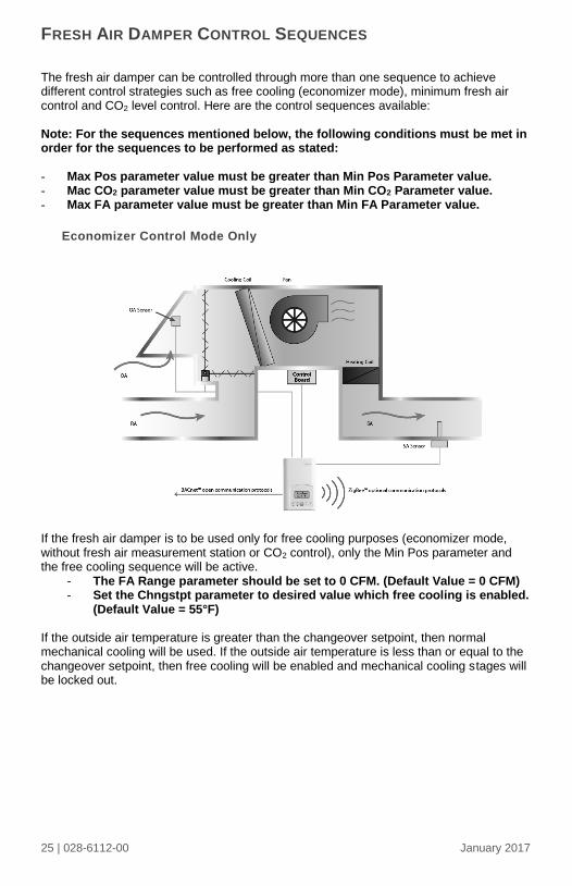
Economizer Control Mode Only
If the fresh air damper is to be used only for free cooling purposes (economizer mode, without fresh air measurement station or CO2 control), only the Min Pos parameter and the free cooling sequence will be active.
- The FA Range parameter should be set to 0 CFM. (Default Value = 0 CFM) - Set the Chngstpt parameter to desired value which free cooling is enabled.
(Default Value = 55°F) If the outside air temperature is greater than the changeover setpoint, then normal mechanical cooling will be used. If the outside air temperature is less than or equal to the changeover setpoint, then free cooling will be enabled and mechanical cooling stages will be locked out.
26 | 028-6112-00 January 2017
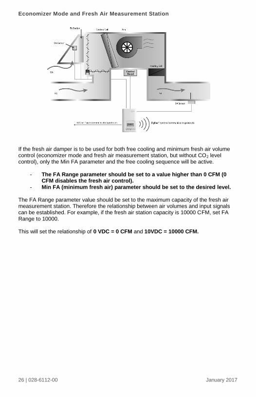
Economizer Mode and Fresh Air Measurement Station
If the fresh air damper is to be used for both free cooling and minimum fresh air volume control (economizer mode and fresh air measurement station, but without CO2 level control), only the Min FA parameter and the free cooling sequence will be active.
- The FA Range parameter should be set to a value higher than 0 CFM (0 CFM disables the fresh air control).
- Min FA (minimum fresh air) parameter should be set to the desired level. The FA Range parameter value should be set to the maximum capacity of the fresh air measurement station. Therefore the relationship between air volumes and input signals can be established. For example, if the fresh air station capacity is 10000 CFM, set FA Range to 10000. This will set the relationship of 0 VDC = 0 CFM and 10VDC = 10000 CFM.

27 | 028-6112-00 January 2017
Economizer Mode and CO2 Level Control
If the fresh air damper is to be used for both free cooling and CO2level control (economizer mode and CO2 level control, but without fresh air measurement station), only the Min Pos, Max Pos, Min CO2and Max CO2 parameters as well as the free cooling sequence will be active.
- The FA Range parameter should be set to 0 CFM. - Set AI1 parameter to CO2 (0 VDC = 0ppm ; 10VDC = 2000ppm) - Min Pos, Max Pos, Min CO2 and Max CO2 parameters should be set
according to the required setting.
The highest value between free cooling demand output and interpolation output for the
fresh air setpoint will be the output to the fresh air damper.
Min Pos
Max Pos
Min CO2 Max CO2
Current Fresh Air Setpoint
Current CO2 Level

28 | 028-6112-00 January 2017
Economizer Mode, CO2 Level Control and Fresh Air Measurement Station
If the fresh air damper is to be used for both free cooling and CO2 level control with a fresh air measurement station, only the Min FA, Max FA, Min CO2 and Max CO2 parameters as well as the free cooling sequence will be active.
- The FA Range parameter should be set to something other than 0 CFM. - Use an air flow transmitter to read fresh air level with AI2 input (0-5 VDC
input) - Min FA, Max FA, Min CO2 and Max CO2 parameters should be set according
to the required setting.
The highest value between free cooling demand output and interpolation output for the
fresh air setpoint based on the CO2 level will be the output to the fresh air damper
Min FA
Setpoint
Max FA
Setpoint
Min CO2 Max CO2
Current
FA Setpoint
Current CO2 Level

29 | 028-6112-00 January 2017
Viconics Technologies Inc.
Tel.: Fax: Toll free:
www.viconics.com


![Rotary Position Sensor Line Guide - Steven Engineering...Terminal type turret turret three 20 AWG, 152,4 mm [6.0 in] leads Resistance range 500 Ohm to 20 kOhm 1 kOhm to 10 kOhm 10000](https://static.fdocuments.net/doc/165x107/609328ecdc62306f8e23a03d/rotary-position-sensor-line-guide-steven-engineering-terminal-type-turret.jpg)