
USER HANDBOOK - Advanced Sensors | Oil in Water … · World s Best Oil in Water Analyzers USER...
42
World’s Best Oil in Water Analyzers USER HANDBOOK: OIW - EX SERIES IN-LINE PROBE OIL IN WATER ANALYZSERS DOCUMENT CODE: 0IW - HBO - 0011 VERSION: EX- 002b
-
Upload
hoangthuan -
Category
Documents
-
view
221 -
download
0
Transcript of USER HANDBOOK - Advanced Sensors | Oil in Water … · World s Best Oil in Water Analyzers USER...

World’s BestOil in WaterAnalyzers
USER HANDBOOK:OIW - EX SERIES IN-LINE PROBE
OIL IN WATER ANALYZSERS
DOCUMENT CODE:
0IW - HBO - 0011
VERSION: EX- 002b
OIW-HBO-0011-EX-002b
OIW EX SERIES - PROBE
U S E R M A N U A L
Rev. 002b MARCH 2014
TABLE OF CONTENTS
TABLE OF CONTENTS _____________________________________________________ 1
HANDBOOK DESCRIPTIONS _________________________________________________ 3
DOCUMENT HISTORY _____________________________________________________ 4
SYMBOLS USED IN THIS HANDBOOK __________________________________________ 4
SECTION 1 - OIW-EX SERIES USER HANDBOOK ___________________________________ 5
1.1 - Introduction _________________________________________________ 5
1.2 - MODES OF OPERATION __________________________________________ 6
1.3 - HEALTH & SAFETY (GENERAL) ____________________________________ 7 1.3.1 - Explosion Safety _____________________________________________ 8 1.3.2 - Electrical Safety _____________________________________________ 8 1.3.3 - Optical Safety ______________________________________________ 8 1.3.4 - Audio Safety _______________________________________________ 8
SECTION 2 - OVERVIEW OF OPERATION ________________________________________ 9
2.1 - Main Window _______________________________________________ 10
2.2 - Display Preferences___________________________________________ 11
SECTION 3 - BASIC SOFTWARE INTERFACE _____________________________________ 12
3.1 - OIW-EX Series Operating System _________________________________ 12
3.2 - Starting the OIW-EX Series _____________________________________ 12
3.3 - CONTROLLING THE OIW SOFTWARE WINDOW _________________________ 13
3.4 - EXITING THE OIW SOFTWARE WINDOW _____________________________ 14
3.5 - SOFTWARE PANEL DESCRIPTIONS _________________________________ 15 3.5.1 - Feedback Display Area (Top Panel) ________________________________ 15
3.5.1.1 - User Alarms __________________________________________ 16 3.5.1.1.1 - PPM Alarms _________________________________________ 16 3.5.1.1.2 - System Log Alarms ____________________________________18 3.5.1.1.3 - Acknowledging and Clearing Alarms ________________________18 3.5.1.1.4 - Alarm Details ________________________________________ 19 3.5.1.1.5 - Laser Life Warning ___________________________________ 20
3.5.2 - Graph Display Area (Middle Panel) ________________________________ 21 3.5.3 - Configuration Settings and Login Area (Lower Panel) __________________ 22
3.5.3.1 - Measurement Cycle Timing Configuration ____________________ 23 3.5.3.2 - Manual Control _______________________________________ 24 3.5.3.2.1 - Start and Stop ______________________________________ 24 3.5.3.2.2 - Saving Changes _____________________________________ 24
8 Meadowbank Road, Carrickfergus, BT38 8YF, Northern Ireland www.advancedsensors.co.uk
Page 1 of 41

OIW-HBO-0011-EX-002b
OIW EX SERIES - PROBE
U S E R M A N U A L
Rev. 002b MARCH 2014
3.6 - Control Options _____________________________________________ 25
3.7 - Ultrasonic Interface ___________________________________________ 26
3.8 - Oil Calibration Settings ________________________________________ 27
3.9 - General Configuration Options Software Interface _____________________ 28
3.9.1 - General Configuration Options (System Settings) _____________________ 28 3.9.2 - General Configuration Options (Display) ___________________________ 29 3.9.3 - General Configuration (Power Up) _______________________________ 29 3.9.4 - General Configuration (Custom Log Files) __________________________ 30 3.9.5 - General Configuration (Password Control) __________________________ 30
3.10 - Schedule Configuration _______________________________________ 31
3.10.1 - Measurement Cycle __________________________________________ 31 3.10.2 - Spectrometer ______________________________________________ 31
3.11 - Alarm Configuration __________________________________________ 32
3.11.1 - PPM Alarms ______________________________________________ 32 3.11.2 - System Alarms ____________________________________________ 33
3.12 - 1 + 1 Configuration __________________________________________ 34
3.13 - Ultrasonic Configuration ______________________________________ 35
3.13.1 - Ultrasonic Settings _________________________________________ 35 3.13.2 - Auto Tuning ______________________________________________ 36 3.13.3 - Factory US Settings ________________________________________ 36
3.14 - Oil Type Configuration ________________________________________ 37
3.14.1 - Oil Type General Information __________________________________ 38 3.14.2 - Oil Type Selection __________________________________________ 38 3.14.3 - Integration Time Offset Control Overview _________________________ 40
3.15 - Restore Last Saved Config _____________________________________ 41
8 Meadowbank Road, Carrickfergus, BT38 8YF, Northern Ireland www.advancedsensors.co.uk
Page 2 of 41

OIW-HBO-0011-EX-002b
OIW EX SERIES - PROBE
U S E R M A N U A L
Rev. 002b MARCH 2014
HANDBOOK DESCRIPTIONS
This handbook is part of a library of that cover the OIW-EX Series of products and the table below indicates the
handbooks available. Please ensure that you have read the latest version of any handbooks required for your job
function.
Code Handbook Description OIW EX Model
OIW-HBO-
100-S 1000-S 100-P 1000-P 100-M 1000-M
0001 Side Stream Installation
Hardware related details required for the physical installation of the side stream OIW-EX Series of units.
X X N/A N/A N/A N/A
0002 User An overview of the operation of the OIW-EX Series of products and details how to configure the unit.
X X X X N/A N/A
0003 Data Logging
Details how to access and examine the data log and system log files. Includes how to use Advanced Sensors LogView and SamTrack software tools and calibration details.
X X X X N/A N/A
0004 Remote Access Details how to access and control the OIW-EX Series of units remotely.
X X X X N/A N/A
0005 Spectrometer
Details how to operate and configure the spectrometer and how to access and examine the associated Spectrometer files. Includes how to use Advanced Sensors SpAn software.
N/A X N/A X N/A N/A
0006 Wireless
Controller Details the set up and use of the handheld wireless controller.
O O O O N/A N/A
0007 Flush Valve Details the operation of units when a Flush Valve is fitted.
O O N/A N/A N/A N/A
0008 Dual Flow Details the operation of Side-Stream units when used in a Dual Flow Mode.
O O N/A N/A N/A N/A
0009 Microscopy Details the operation of units fitted with the Microscopy system and how to examine the microscopy files.
O O N/A N/A N/A N/A
0010 HART Details the HART commands implemented, for use with units fitted with a HART modem interface.
O O O O N/A N/A
0011 In-Line Probe
User
An overview of the operation of the OIW-EX P Series of products and details how to configure the unit.
N/A N/A X X N/A N/A
0012 In-Line Probe Installation
Hardware related details required for the physical installation of the In-Line probe OIW-EX P Series of units.
N/A N/A X X N/A N/A
0013 MiView Details on how to use the client software for Microscopy Analysers
N/A N/A N/A N/A N/A N/A
8 Meadowbank Road, Carrickfergus, BT38 8YF, Northern Ireland www.advancedsensors.co.uk
Page 3 of 41

OIW-HBO-0011-EX-002b
OIW EX SERIES - PROBE
U S E R M A N U A L
Rev. 002b MARCH 2014
DOCUMENT HISTORY
Change No. Version No. Description Release Date
0 A (Draft) First draft. 17th July 2009
1 B (Draft) Second draft 2nd March 2010
2 2a Major styling / layout changes & introduction of more detailed information, including new screenshots.
18th June 2012
3 2b Updated to new corporate formatting. Removal of Ex 11 2 G EEx d 11B T4 from Section 1.1.
24th March 2014
SYMBOLS USED IN THIS HANDBOOK
The symbol is used throughout this document to draw attention to important information.
The definitions of each term used where it is found are as follows:
CAUTION An instruction that draws attention to the risk of damage to the product, process or surroundings.
INFORMATION Further reference for more detailed information or technical details.
NOTE Clarification of an instruction or additional information.
WARNING An instruction that draws attention to the risk of injury or death.
WARNING: Although Warning hazards are related to potential personal injury, and Caution hazards are associated with material damage, it must be understood that operation of damaged equipment could lead to personal injury or death. All Warning and Caution hazards must be
complied with.
8 Meadowbank Road, Carrickfergus, BT38 8YF, Northern Ireland www.advancedsensors.co.uk
Page 4 of 41

OIW-HBO-0011-EX-002b
OIW EX SERIES - PROBE
U S E R M A N U A L
Rev. 002b MARCH 2014
SECTION 1 - OIW-EX SERIES USER HANDBOOK
1.1 - INTRODUCTION
This User handbook provides user information on how to use and configure the Advanced Sensors Ltd OIW-EX Series of
Oil in Water Monitor Probe Systems.
NOTE: This handbook as description of both describes both single and dual probe systems
The system is designed to monitor the residual hydrocarbon content of pipelines carrying produced water at oil
processing facilities etc.
The OIW-EX Series of Oil in Water Monitor Systems uses laser radiation to energise the contents of the measurement
chamber with an incident optical wavelength. A sensitive tuned detector at a different wavelength is then used to
measure the stimulated fluorescence value. This fluorescence value is used to determine the proportion of hydrocarbons
within the chamber.
To overcome the problem of contamination of the optical path a proprietary self-cleaning technique has been
incorporated. The cleaning process is user-configurable to accommodate a wide variation of environmental conditions.
The equipment has a user friendly windows based display providing a wealth of information. Industry standard outputs
include a 4-20 mA output as a measurement of oil content over a provisionable range, an RS-232 data output and an
Ethernet port over which the user can either receive data, or remotely control the unit.
The equipment is designed for installation in potentially explosive atmospheres and is certified to ATEX Directive
(94/9/EC) Ex ll 2 G Ex d/de llB T4.
CAUTION: This manual describes the operation and use of the unit NOT the installation.
Ensure that the unit has been correctly installed in line with the In-Line Probe Installation Handbook (OIW-HBO-0012)
prior to use.
Should you have any questions or comments regarding anything within in this handbook, please contact us at address
shown below:
Advanced Sensors Ltd
8 Meadowbank Road
Carrickfergus
BT38 8YF
UK
Tel: +44 (0)28 93 32 89 22 Fax: +44 (0)28 93 32 86 69
Web: www.advancedsensors.co.uk
8 Meadowbank Road, Carrickfergus, BT38 8YF, Northern Ireland www.advancedsensors.co.uk
Page 5 of 41

OIW-HBO-0011-EX-002b
OIW EX SERIES - PROBE
U S E R M A N U A L
Rev. 002b MARCH 2014
1.2 - MODES OF OPERATION
The OIW-EX Series have been designed with maximum flexibility in mind enabling them to be configured in a variety of
ways to suit different customer requirements.
NOTE: There are 3x levels of User Access, namely “Limited”, “Standard” and “Full”.
Functionality is restricted at certain user levels and this will be highlighted throughout the document.
8 Meadowbank Road, Carrickfergus, BT38 8YF, Northern Ireland www.advancedsensors.co.uk
Page 6 of 41

OIW-HBO-0011-EX-002b
OIW EX SERIES - PROBE
U S E R M A N U A L
Rev. 002b MARCH 2014
1.3 - HEALTH & SAFETY (GENERAL)
1. The equipment must only be operated when there is water the process pipe. Failure to observe this
requirement may result in damage to the equipment.
2. Always isolate the power to the system prior to opening the unit.
3. Do not open the unit when an explosive gas atmosphere may be present.
4. Warning labels on the equipment and packaging must be observed.
5. Installation and maintenance must only be carried out by suitably trained personnel, in accordance with the
information in this manual, and under local Health and Safety procedures.
6. Safety precautions must be taken when working with associated pipe work that may be subjected to internal
pressure or high temperatures.
7. There are no user-serviceable parts within the unit. Any unauthorized repairs or modifications will not be
under-written by the manufacturer.
8. Given the heavy weight of the equipment it is important that suitable PPE is worn and that local Manual
Handling safety procedures are followed.
9. The equipment must only be installed and operated as instructed in this document. Failure to comply with
these instructions may compromise the equipment’s protection features leading to potentially dangerous
consequences or, it may cause the system to not operate correctly.
10. An annual service is recommended and should only be performed by the vendor (Advanced Sensors Ltd.) or
their approved agent to ensure ongoing optimum performance. No day-to-day maintenance is required.
11. The equipment is contained within a flameproof enclosure. To maintain the certification of this unit, the
enclosure must not be damaged and the integrity of this is only intact if the status of the equipment as
manufactured is maintained. No parts must be replaced, modified or substituted without reference to the
manufacturer or their representative.
12. If any physical damage occurs to the sealed enclosure power must be removed immediately and the
manufacturer or their representative contacted for servicing.
13. The In-Line Probe assembly (including Extraction / Insertion Assembly) weighs approximately 45 kg. It is the
customer’s responsibility to ensure appropriate H&S compliance for the movement and manual handling of
this mass.
14. The Extraction / Insertion Assembly and associated couplings have been design tested to 30 bar pressure. It
is the customer’s responsibility to ensure that the process fluid pressure to the system does not exceed this
level.
15. In installations where the process water temperature may be high it is the customer’s responsibility to comply
with any regional H&S signage requirements.
8 Meadowbank Road, Carrickfergus, BT38 8YF, Northern Ireland www.advancedsensors.co.uk
Page 7 of 41

OIW-HBO-0011-EX-002b
OIW EX SERIES - PROBE
U S E R M A N U A L
Rev. 002b MARCH 2014
1.3.1 - Explosion Safety
1. The equipment is contained within a flameproof enclosure. To maintain the certification of this unit, the
enclosure must not be damaged and the integrity of this is only intact if the status of the equipment as
manufactured is maintained. No parts must be replaced, modified or substituted without reference to the
manufacturer or their representative.
2. If any physical damage occurs to the sealed enclosure, glazed window or connection glands, then the power
must be removed immediately and the manufacturer or their representative contacted for servicing.
3. The enclosure must be grounded via the external earth point provided, using an earth conductor meeting the
local authority electrical regulations.
4. There are no user-serviceable parts within the unit; there should be no requirement for the door to be opened
with power applied other than for installation and servicing. All servicing, installation and repairs must be
carried out by the manufacturer or their representative. Any unauthorized repairs or modifications will not be
under-written by the manufacturer. In certain environments the equipment may present a potential source of
ignition when the enclosure is opened whilst powered; procedures appropriate to local site ‘hot’ working must
be adhered to. When closed, all 14 of the cap-head bolts around the periphery of the door must be set to a
torque of 30 Nm.
5. All unused ports in the base of the enclosure must have an EExd approved brass M25 plug fitted. The torque
setting for these plugs is 33 Nm.
1.3.2 - Electrical Safety
There are two variants of the system which are designed to operate off either a nominal 110VAC or 220VAC supply.
These conform to EN61010-1 2001 Part 1. It is the responsibility of the installer to ensure compliance with the regional
requirements for electrical safety regarding the provision of a compliant earth, earth bonding, adjacent electrical
isolation and circuit protection.
NOTE: Ensure the correct voltage supply is available on site before commencing installation. 1.3.3 - Optical Safety
The system uses a Class 3R laser as part of its measurement process. The light from this source is contained within the
measurement chamber and is safe during normal operation.
WARNING: Power should not be applied when the unit is in a disassembled state. 1.3.4 - Audio Safety
The system uses ultrasonic cleaning technology, which will operate periodically and conforms to EN61010-1 2001 Part 1.
WARNING: When the ultrasonic device is in operation the average sound level may exceed safe levels, therefore suitable ear defenders must be worn and recognised signs posted to identify the potential hazard.
8 Meadowbank Road, Carrickfergus, BT38 8YF, Northern Ireland www.advancedsensors.co.uk
Page 8 of 41

OIW-HBO-0011-EX-002b
OIW EX SERIES - PROBE
U S E R M A N U A L
Rev. 002b MARCH 2014
SECTION 2 - OVERVIEW OF OPERATION
The OIW User Handbook OIW-HBO-0002, with the Measurement Cycle with the standard side-Stream Configuration.
Figure 1 below shows the Measurement Cycle of the OIW In-Line Probe.
The Measurement Cycle with the OIW In-Line Probe is greatly simplified compared with the Standard OIW-EX Series as
there are no valves to control as there would be in a Side-Stream configuration.
Figure 1: OIW-EX100P and 1000P In-Line Probe Measurement Cycle
8 Meadowbank Road, Carrickfergus, BT38 8YF, Northern Ireland www.advancedsensors.co.uk
Page 9 of 41

OIW-HBO-0011-EX-002b
OIW EX SERIES - PROBE
U S E R M A N U A L
Rev. 002b MARCH 2014
2.1 - MAIN WINDOW
In Figure 2 below the Main Window is shown with a representation of the measurement cycle of an OIW-EX1000P. In
this example, the Measurement Cycle field shows that OIW-EX1000P will measure for 1 hr, () then clean for 20
seconds ():
Figure 2: OIW-EX Main Window
8 Meadowbank Road, Carrickfergus, BT38 8YF, Northern Ireland www.advancedsensors.co.uk
Page 10 of 41

OIW-HBO-0011-EX-002b
OIW EX SERIES - PROBE
U S E R M A N U A L
Rev. 002b MARCH 2014
2.2 - DISPLAY PREFERENCES
Users can change screen configurations to suit their own requirement using the circled buttons in the examples below:
8 Meadowbank Road, Carrickfergus, BT38 8YF, Northern Ireland www.advancedsensors.co.uk
Page 11 of 41

OIW-HBO-0011-EX-002b
OIW EX SERIES - PROBE
U S E R M A N U A L
Rev. 002b MARCH 2014
SECTION 3 - BASIC SOFTWARE INTERFACE
3.1 - OIW-EX SERIES OPERATING SYSTEM
The OIW-EX Series of monitors runs on a standard Windows XP Pro user operating system. This manual assumes that
users have a basic competence in using Windows XP. In everyday use the system requires minimal access to Windows
XP. It is primarily used to gain access to the data logs stored on the hard drive.
3.2 - STARTING THE OIW-EX SERIES
On completion of the installation the system is ready to be turned on. The power up sequence takes approximately 3
minutes. During this time a variety of system level message are displayed on the screen (no user action is required). The
Windows XP operating system starting message will appear, followed by the OIW-EX unit’s start-up window , e.g.:
Figure 3: OIW-EX Start-up Window
NOTE: During power-up some information will be displayed rotated through 90o. This is normal operation and will orientate correctly on completion.
When the OIW software starts it will automatically detect the hardware configuration and will indicate the model type in
the header bar of the window, as highlighted in the example below:
8 Meadowbank Road, Carrickfergus, BT38 8YF, Northern Ireland www.advancedsensors.co.uk
Page 12 of 41

OIW-HBO-0011-EX-002b
OIW EX SERIES - PROBE
U S E R M A N U A L
Rev. 002b MARCH 2014
3.3 - CONTROLLING THE OIW SOFTWARE WINDOW
As can be seen the OIW control software is based on a standard Windows XP interface and the following control buttons are available in the upper right-hand corner:
• = Minimize
• = Reduce in size
• = Maximize
• = Exit
The software starts up in full screen and should be left that way for standard operation. It can be minimised or reduced
in size when the user wishes to perform routine admin tasks such as backing up the data log files etc. The software will
continue to function during reduced or minimised states.
To prevent the user from accidentally minimising or exiting the unit while the measurement cycle is running the control
buttons are hidden as shown below in Figures 4 and 5:
Figure 4: Control Buttons (Application Stopped) Figure 5: Control Buttons (Application Running)
NOTE: When the unit in running the OIW software window can still be dragged across the screen.
8 Meadowbank Road, Carrickfergus, BT38 8YF, Northern Ireland www.advancedsensors.co.uk
Page 13 of 41

OIW-HBO-0011-EX-002b
OIW EX SERIES - PROBE
U S E R M A N U A L
Rev. 002b MARCH 2014
3.4 - EXITING THE OIW SOFTWARE WINDOW
When the measurement cycle is stopped and the control icons are visible the user can exit the OIW software by clicking
the exit button .
To avoid accidental and/or unauthorised exiting of the software, a warning box will appear in the centre of the screen
when the exit button is clicked, as shown below in Figure 6.
Figure 6: Exit Confirmation box
This box will prompt the user for the admin password.
• If the incorrect password is entered then a system log will be generated highlighting an exit attempt
has failed.
• If the correct password is entered then a system log will be generated highlighting that the OIW
software has shutdown normally.
While the OIW unit has been designed to handle sudden shutdown i.e. the unit is powered down immediately, exiting the
software in this way ensures that there is traceability of the user’s actions.
CAUTION:
1. Unless maintenance is being carried out by authorized personnel there is no requirement for the software to be exited.
2. If there is any concern about normal operation of the unit, the window should be shut down and the unit powered down at the main power isolation point.
8 Meadowbank Road, Carrickfergus, BT38 8YF, Northern Ireland www.advancedsensors.co.uk
Page 14 of 41
OIW-HBO-0011-EX-002b
OIW EX SERIES - PROBE
U S E R M A N U A L
Rev. 002b MARCH 2014
3.5 - SOFTWARE PANEL DESCRIPTIONS
As can be seen in Figure 2 on page 14, the software is split into three screen panels.
This section provides details on each panel. It also describes the admin panel which is visible when a user logs in via the
admin password.
3.5.1 - Feedback Display Area (Top Panel)
This panel provides the user with feedback on the operation of the system and an example can be seen below in Figure
7:
Figure 7: Feedback Display Area
Details are shown below:
1 PPM
display
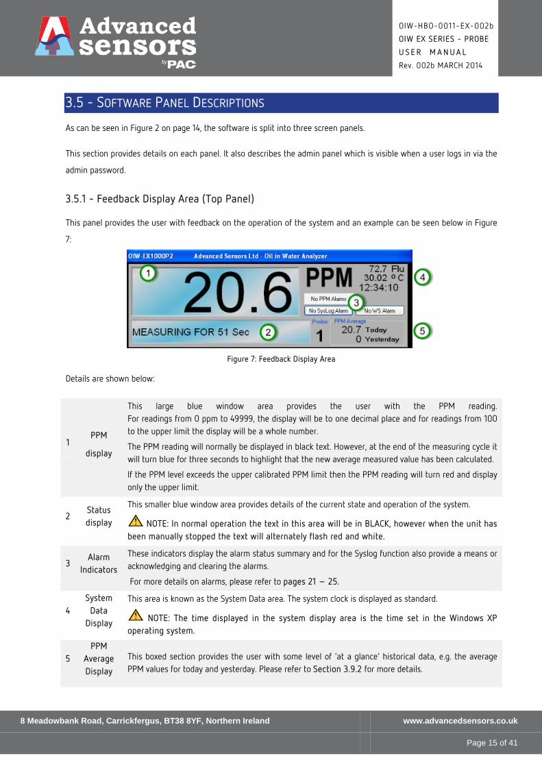
This large blue window area provides the user with the PPM reading. For readings from 0 ppm to 49999, the display will be to one decimal place and for readings from 100 to the upper limit the display will be a whole number.
The PPM reading will normally be displayed in black text. However, at the end of the measuring cycle it will turn blue for three seconds to highlight that the new average measured value has been calculated.
If the PPM level exceeds the upper calibrated PPM limit then the PPM reading will turn red and display only the upper limit.
2 Status display
This smaller blue window area provides details of the current state and operation of the system.
NOTE: In normal operation the text in this area will be in BLACK, however when the unit has been manually stopped the text will alternately flash red and white.
3 Alarm
Indicators
These indicators display the alarm status summary and for the Syslog function also provide a means or acknowledging and clearing the alarms.
For more details on alarms, please refer to pages 21 – 25.
4 System
Data Display
This area is known as the System Data area. The system clock is displayed as standard.
NOTE: The time displayed in the system display area is the time set in the Windows XP operating system.
5 PPM
Average Display
This boxed section provides the user with some level of ‘at a glance’ historical data, e.g. the average PPM values for today and yesterday. Please refer to Section 3.9.2 for more details.
8 Meadowbank Road, Carrickfergus, BT38 8YF, Northern Ireland www.advancedsensors.co.uk
Page 15 of 41

OIW-HBO-0011-EX-002b
OIW EX SERIES - PROBE
U S E R M A N U A L
Rev. 002b MARCH 2014
3.5.1.1 - User Alarms
There are two types of alarm condition:
• Alarms generated as a result of PPM thresholds being exceeded.
• Alarms generated as a result of System Logs being generated.
Each of these alarm conditions is represented by a multi-function button on the top panel just below the PPM legend.
3.5.1.1.1 - PPM Alarms
With no alarm conditions met, the ppm Alarm button will be displayed as shown below in Figure 12, i.e. with a grey
background and the text No PPM Alarms on the button. When in this state moving the mouse over or selecting this
button will have no effect.
Figure 8: No PPM alarm
For explanation purposes th ppm alarm trigger for Probe 1 has be set to 20 ppm. As can be seen above in Figure 12, with
the ppm level below this trigger valve the ppm alarm button continues to display No PPM Alarms. However, if the ppm
level rises above 20 ppm then the button will turn red and the text will highlight the alarm condition by changing to read
PPM Alarm Probe 1 as shown below in Figure 9:
Figure 9: PPM Alarm Level Exceeded
8 Meadowbank Road, Carrickfergus, BT38 8YF, Northern Ireland www.advancedsensors.co.uk
Page 16 of 41
OIW-HBO-0011-EX-002b
OIW EX SERIES - PROBE
U S E R M A N U A L
Rev. 002b MARCH 2014
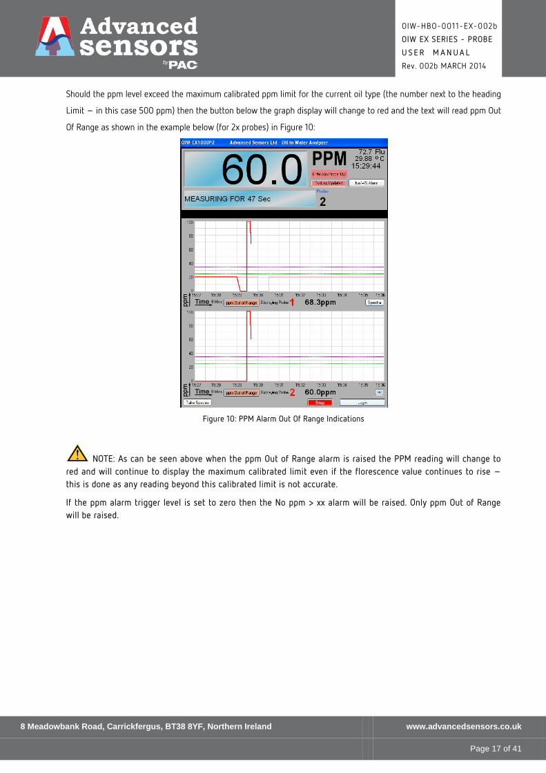
Should the ppm level exceed the maximum calibrated ppm limit for the current oil type (the number next to the heading
Limit – in this case 500 ppm) then the button below the graph display will change to red and the text will read ppm Out
Of Range as shown in the example below (for 2x probes) in Figure 10:
Figure 10: PPM Alarm Out Of Range Indications
NOTE: As can be seen above when the ppm Out of Range alarm is raised the PPM reading will change to red and will continue to display the maximum calibrated limit even if the florescence value continues to rise – this is done as any reading beyond this calibrated limit is not accurate.
If the ppm alarm trigger level is set to zero then the No ppm > xx alarm will be raised. Only ppm Out of Range will be raised.
8 Meadowbank Road, Carrickfergus, BT38 8YF, Northern Ireland www.advancedsensors.co.uk
Page 17 of 41
OIW-HBO-0011-EX-002b
OIW EX SERIES - PROBE
U S E R M A N U A L
Rev. 002b MARCH 2014
3.5.1.1.2 - System Log Alarms
System logs (SysLog for short) represent a record of events that have occurred during the operation of the unit. For
information on system logs, please refer to the Data Logging Handbook (OIW-HBO-0003).
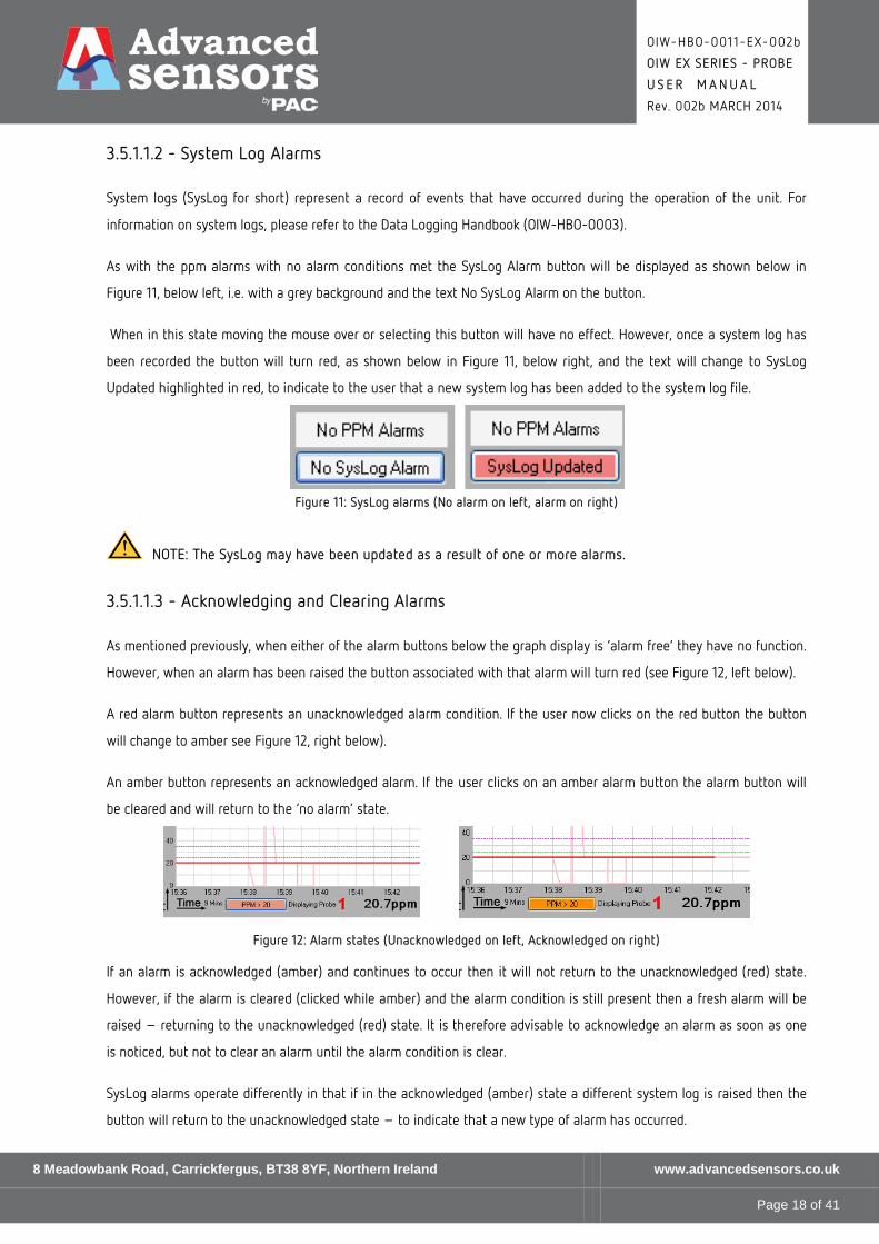
As with the ppm alarms with no alarm conditions met the SysLog Alarm button will be displayed as shown below in
Figure 11, below left, i.e. with a grey background and the text No SysLog Alarm on the button.
When in this state moving the mouse over or selecting this button will have no effect. However, once a system log has
been recorded the button will turn red, as shown below in Figure 11, below right, and the text will change to SysLog
Updated highlighted in red, to indicate to the user that a new system log has been added to the system log file.
Figure 11: SysLog alarms (No alarm on left, alarm on right)
NOTE: The SysLog may have been updated as a result of one or more alarms.
3.5.1.1.3 - Acknowledging and Clearing Alarms
As mentioned previously, when either of the alarm buttons below the graph display is ‘alarm free’ they have no function.
However, when an alarm has been raised the button associated with that alarm will turn red (see Figure 12, left below).
A red alarm button represents an unacknowledged alarm condition. If the user now clicks on the red button the button
will change to amber see Figure 12, right below).
An amber button represents an acknowledged alarm. If the user clicks on an amber alarm button the alarm button will
be cleared and will return to the ‘no alarm’ state.
Figure 12: Alarm states (Unacknowledged on left, Acknowledged on right)
If an alarm is acknowledged (amber) and continues to occur then it will not return to the unacknowledged (red) state.
However, if the alarm is cleared (clicked while amber) and the alarm condition is still present then a fresh alarm will be
raised – returning to the unacknowledged (red) state. It is therefore advisable to acknowledge an alarm as soon as one
is noticed, but not to clear an alarm until the alarm condition is clear.
SysLog alarms operate differently in that if in the acknowledged (amber) state a different system log is raised then the
button will return to the unacknowledged state – to indicate that a new type of alarm has occurred.
8 Meadowbank Road, Carrickfergus, BT38 8YF, Northern Ireland www.advancedsensors.co.uk
Page 18 of 41

OIW-HBO-0011-EX-002b
OIW EX SERIES - PROBE
U S E R M A N U A L
Rev. 002b MARCH 2014
3.5.1.1.4 - Alarm Details
Every time an alarm is raised, acknowledged or cleared this information is stored in the data log (please refer to the Data
Logging Handbook (OIW-HBO-0003) for more information. In this way there is complete traceability of what is
happening. In addition to this long term traceability the user can place the mouse over the button (without clicking the
button) and a message box will appear between the upper and middle panels. This message box will provide the user
with quick reference to when and what alarm was raised.
Figure 14 below shows an example of this. When the user returns to the OIW at 15:41:25 they notice that a PPM alarm
has been raised for Probe 1. When they place the mouse over the ppm alarm button the alarm message box appears. The
message box indicates that at 12:41:55 the ppm level exceeded 15 ppm. Having seen the alarm the user can acknowledge
the alarm by now clicking the alarm button and the button will now turn to amber.
With the button in the acknowledged (amber) state if a second user were to view the screen they would be aware that
this alarm has been seen. If the mouse is now placed over alarm button (see Figure 15 below) additional information is
available, indicating not only what time the alarm was raised (i.e. 15:41:25), but also what time the alarm was
acknowledged ( i.e.15:42:06).
In the example below, the ppm value is still above 20 ppm so if the user clears this alarm (clicks on the amber alarm
button) a fresh alarm will be raised. It is therefore best to leave the alarm at acknowledged (amber) until action has
been taken to reduce the ppm level below the trigger level.
System logs differ in that if other alarms are raised before the first is cleared then the alarm details box will indicate that
other logs have been made by displaying Other Logs in the message text.
Figure 13: Alarm Raised display Figure 14: Alarm Acknowledged display
8 Meadowbank Road, Carrickfergus, BT38 8YF, Northern Ireland www.advancedsensors.co.uk
Page 19 of 41
OIW-HBO-0011-EX-002b
OIW EX SERIES - PROBE
U S E R M A N U A L
Rev. 002b MARCH 2014
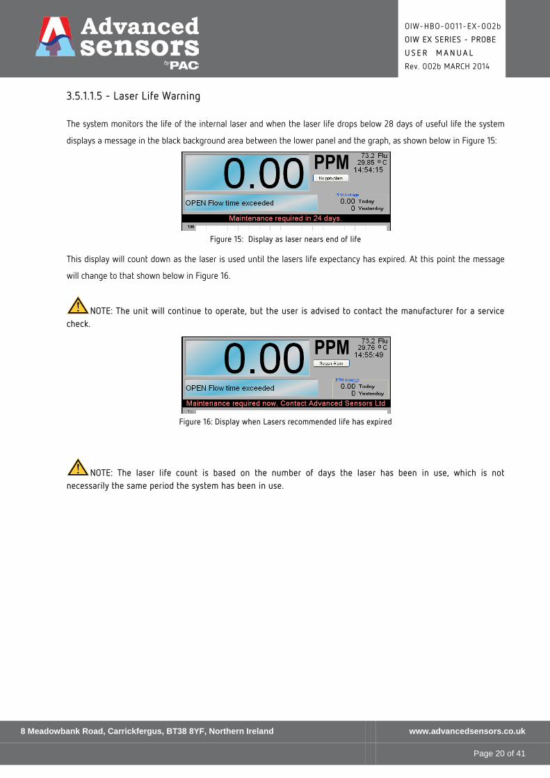
3.5.1.1.5 - Laser Life Warning
The system monitors the life of the internal laser and when the laser life drops below 28 days of useful life the system
displays a message in the black background area between the lower panel and the graph, as shown below in Figure 15:
Figure 15: Display as laser nears end of life
This display will count down as the laser is used until the lasers life expectancy has expired. At this point the message
will change to that shown below in Figure 16.
NOTE: The unit will continue to operate, but the user is advised to contact the manufacturer for a service check.
Figure 16: Display when Lasers recommended life has expired
NOTE: The laser life count is based on the number of days the laser has been in use, which is not necessarily the same period the system has been in use.
8 Meadowbank Road, Carrickfergus, BT38 8YF, Northern Ireland www.advancedsensors.co.uk
Page 20 of 41

OIW-HBO-0011-EX-002b
OIW EX SERIES - PROBE
U S E R M A N U A L
Rev. 002b MARCH 2014
3.5.2 - Graph Display Area (Middle Panel)
The graph panel is the central panel on the screen and an example is shown below in Figure 17. This panel provides a
graphical display of the PPM readings.
The PPM Reading scale can be changed when the user is logged in for values in the range 1 ppm to 50,000 ppm.
The time scale can also be changed when the user is logged in for the following values:
• 9 minutes
• 1.5 hours
• 6 hours
• 24 hours
Figure 17: Graph Display Panel Area
8 Meadowbank Road, Carrickfergus, BT38 8YF, Northern Ireland www.advancedsensors.co.uk
Page 21 of 41
OIW-HBO-0011-EX-002b
OIW EX SERIES - PROBE
U S E R M A N U A L
Rev. 002b MARCH 2014
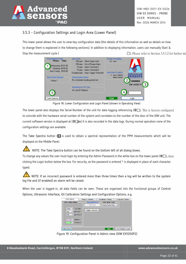
3.5.3 - Configuration Settings and Login Area (Lower Panel)
This lower panel allows the user to view key configuration data (the details of this information as well as details on how
to change them is explained in the following sections). In addition to displaying information, users can manually Start &
Stop the measurement cycle ( ). Please refer to Section 3.5.3.2 for further inf
Figure 18: Lower Configuration and Login Panel (shown in Operating View)
The lower panel also displays the Serial Number of the unit for data logging referencing (). This is factory configured
to coincide with the hardware serial number of the system and correlates to the number of the door of the OIW unit. The
current software version is displayed at () and it is also recorded in the data logs. During normal operation none of the
configuration settings are available.
The Take Spectra button (5) is used to obtain a spectral representation of the PPM measurements which will be
displayed on the Middle Panel.
NOTE: The Take Spectra button can be found on the bottom left of all dialog boxes.
To change any values the user must login by entering the Admin Password in the white box on the lower panel (), then
clicking the Login button below the box. For security, as the password is entered * is displayed in place of each character
typed.
NOTE: If an incorrect password is entered more than three times then a log will be written to the system log file and (if enabled) an alarm will be raised. When the user is logged-in, all data fields can be seen. These are organised into the functional groups of Control
Options, Ultrasonic Interface, Oil Calibration Settings and Configuration Options, e.g.
Figure 19: Configuration Panel in Admin view (OIW EX1000P2)
8 Meadowbank Road, Carrickfergus, BT38 8YF, Northern Ireland www.advancedsensors.co.uk
Page 22 of 41

OIW-HBO-0011-EX-002b
OIW EX SERIES - PROBE
U S E R M A N U A L
Rev. 002b MARCH 2014
3.5.3.1 - Measurement Cycle Timing Configuration
The measurement cycle data can be found on the left-hand side of the Lower Panel when in normal operational mode,
e.g.:
Figure 20: Measurement Cycle (Flow in Progress)
NOTE: The display will change based on individual configurations.
8 Meadowbank Road, Carrickfergus, BT38 8YF, Northern Ireland www.advancedsensors.co.uk
Page 23 of 41

OIW-HBO-0011-EX-002b
OIW EX SERIES - PROBE
U S E R M A N U A L
Rev. 002b MARCH 2014
3.5.3.2 - Manual Control
Manual control enables a user to start and stop the measurement cycle. It is accessible to all users and does not require
a login access.
3.5.3.2.1 - Start and Stop
At power up the Manual Control button will appear in the bottom-right of the bottom panel, e.g.:
When the Start button is clicked, the unit will start from the measurement cycle as defined in Section 3.10.1 and the
button changes to Stop, e.g.:
Clicking on Stop will halt the current measurement cycle; the display will return to the start state and will indicate CYCLE
STOPPED (see NOTE below).
NOTE: In normal operation the text in the display area is BLACK, however when the unit has been manually stopped the text will flash RED and WHITE.
3.5.3.2.2 - Saving Changes
Any changes made in this view will take effect immediately and allow the user to see the result of these changes.
However, these changes will not be stored for later use until the Save Changes & Logout button shown below is clicked:
NOTE: If the unit is powered down or the OIW Software shutdown after changes have been made, but before the changes have been saved then these changes will be lost.
8 Meadowbank Road, Carrickfergus, BT38 8YF, Northern Ireland www.advancedsensors.co.uk
Page 24 of 41

OIW-HBO-0011-EX-002b
OIW EX SERIES - PROBE
U S E R M A N U A L
Rev. 002b MARCH 2014
3.6 - CONTROL OPTIONS
This dialog box allows users to set display and activation parameters as detailed in the table underneath.
Figure 21: Control Options dialog box (OIW EX1000P2)
The options available are as follows:
Graph Display Settings
This allows you to plot either the Trending or the Measured value and to change the
axes of the Graph. In addition guidelines, in purple or green, may be drawn on the
graph as a visual guide.
Simulation Enabled
This option facilitates commissioning and diagnostics and allows the user to set the
PPM value, temperature or florescence settings. This selection can only be used while
in the admin view. The default state at login is Simulation Enabled not checked
meaning the actual values are being used and simulation is off. If the user has
Simulation Enabled checked and logs-out, the simulation will revert to actual; i.e.
simulation settings are not saved and only remain in force while a maintenance user
is logged-in.
This can be useful in calibrating the 4-2 0mA e.g. the user can set the PPM value to 0
and then to 100 ppm and ensure that 4 mA and 20 mA respectively are displayed. This
feature is used during test and setup and only permits whole numbers to be entered.
NOTE: When the PPM is simulated the displayed Flu value should be ignored as the system does not re-calculate the Flu value.
However when Flu or Temp are simulated the displayed PPM value will be the calculated value resulting from the simulated value set.
Probe Display Toggle This allows users to select which probe or combination of probe information is to be
displayed on the Middle Panel.
Trigger Tune Cycle This allows users to carry out an Auto Tune at the end of a measurement cycle.
8 Meadowbank Road, Carrickfergus, BT38 8YF, Northern Ireland www.advancedsensors.co.uk
Page 25 of 41
OIW-HBO-0011-EX-002b
OIW EX SERIES - PROBE
U S E R M A N U A L
Rev. 002b MARCH 2014
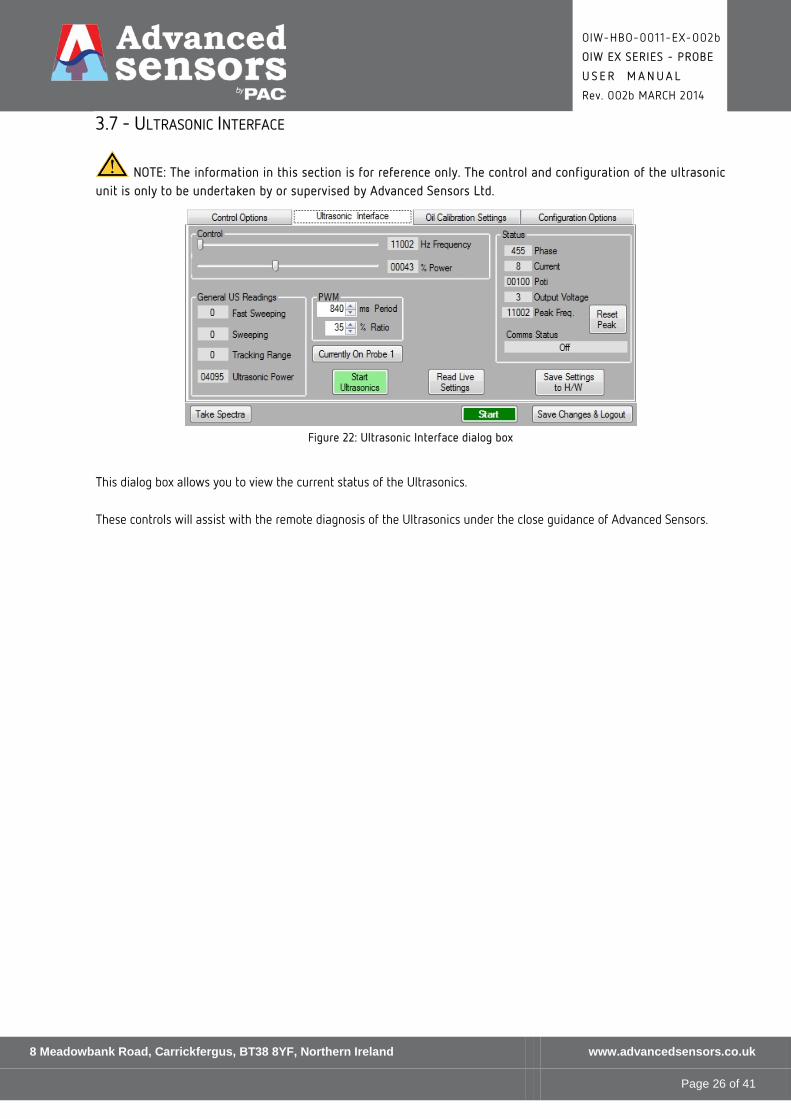
3.7 - ULTRASONIC INTERFACE
NOTE: The information in this section is for reference only. The control and configuration of the ultrasonic unit is only to be undertaken by or supervised by Advanced Sensors Ltd.
Figure 22: Ultrasonic Interface dialog box
This dialog box allows you to view the current status of the Ultrasonics.
These controls will assist with the remote diagnosis of the Ultrasonics under the close guidance of Advanced Sensors.
8 Meadowbank Road, Carrickfergus, BT38 8YF, Northern Ireland www.advancedsensors.co.uk
Page 26 of 41

OIW-HBO-0011-EX-002b
OIW EX SERIES - PROBE
U S E R M A N U A L
Rev. 002b MARCH 2014
3.8 - OIL CALIBRATION SETTINGS
The options available are as follows:
Gain Control This allows you set the gain of the Sensor in the OIW Monitor. This is not normally changed after calibration has been completed
Offset Control This allows you set the offset of the Sensor in the OIW Monitor. This is not normally changed after calibration has been completed.
Flu Reading This show the current Flu, Fluorescence which is also displayed in the top right hand part of the Top Panel of the Main Window.
Spectrometer Standard Creation Please refer to the Spectrometer Handbook (OIW-HBO-0005) for further details.
8 Meadowbank Road, Carrickfergus, BT38 8YF, Northern Ireland www.advancedsensors.co.uk
Page 27 of 41

OIW-HBO-0011-EX-002b
OIW EX SERIES - PROBE
U S E R M A N U A L
Rev. 002b MARCH 2014
3.9 - GENERAL CONFIGURATION OPTIONS SOFTWARE INTERFACE
The following relates to OIW-EX Series of systems with software version 4.01.11.
The bottom third of the OIW monitor software is given over to the Configuration Tabs when you are logged in (please
refer to Section 3.5.3 for details on how to log in).
When you log in for the first time the OIW monitor software shows the General Settings tab. Subsequent logins will
show the last tab that was used. The tabs use the standard Windows tab convention for operation and each dialog box
will be described as shown to a logged in user.
NOTE: The current user is identified by a number displayed at the bottom-left of each dialog box.
3.9.1 - General Configuration Options (System Settings)
The System Settings dialog box is shown below in Figure 23 and the options are described in the table underneath:
Figure 23: General Configuration System Settings dialog box
20mA Value Allows the user to select the PPM reading which will give full range at 20mA. As can be seen above in Figure 23, the default is set to 50ppm for 20mA but it can be adjusted via the drop down box.
Network
Controller
Access
This allows the OIW Monitor, in conjunction with other Advanced Sensors technologies, e.g. to send SMS text messages and eimails, Please refer to the Advanced Sensors Remote Access Handbook (OIW-HBO-0004) for further information.
Active Probes Selects which probe(s) are to be used for measurement.
Display
Averaging
The PPM reading by default is not averaged and will be displayed on a second by second basis. However this can lead to distracting jumps in readings from time to time. To avoid this, the Display Average selection can be set to display the average PPM value over a selection of time periods as below. This selection is made in the Admin view.
NOTE: Display Averaging affects the PPM reading on the screen and on the 4-20 mA line, but does not affect the PPM reading sent to the data log file and does not alter the Flu reading on the system display area or the Flu reading within the file.
Custom Tag Allows a user to insert a custom text file which will be displayed on the Main Window underneath the serial number and software information.
8 Meadowbank Road, Carrickfergus, BT38 8YF, Northern Ireland www.advancedsensors.co.uk
Page 28 of 41

OIW-HBO-0011-EX-002b
OIW EX SERIES - PROBE
U S E R M A N U A L
Rev. 002b MARCH 2014
3.9.2 - General Configuration Options (Display)
The Display dialog allows the user to select the Temperature to be displayed on the as either °C or °F, e.g.:
Figure 24: General Configuration Display dialog box
There are also an option to show average readings of PPM over a 24 hr period and this is selected from the drop-down
menu in the Additional Data Displayed section, e.g.:
The average readings will then be displayed on the top panel, e.g.:
3.9.3 - General Configuration (Power Up)
This dialog box allows users to set the OIW monitor to be re-started in a specified state after power has been re-stored
following a power failure.
8 Meadowbank Road, Carrickfergus, BT38 8YF, Northern Ireland www.advancedsensors.co.uk
Page 29 of 41

OIW-HBO-0011-EX-002b
OIW EX SERIES - PROBE
U S E R M A N U A L
Rev. 002b MARCH 2014
3.9.4 - General Configuration (Custom Log Files)
The Custom Log Files dialog box allows users to choose whether to write a custom log file in addition to the standard
OIW data file and to choose the content of those Custom Log Files, e.g.:
To enable the saving of Custom data, simply check the Enable Custom Log Files box and the boxes for those data
parameters you wish to record.
The Data Log Frequency selection allows you to choose to save a day’s data in one or two files. A single OIW data file
will save a data entry for each of the 86,400 seconds in day. Two files may be useful if you are running older versions of
Excel and other mathematical analyses programs that are limited to 65,000 data points.
3.9.5 - General Configuration (Password Control)
This allows the configuration of up to seven unique passwords (User No. 0 through to User No. 6):
NOTE: This dialog box cannot be accessed in Limited User mode.
8 Meadowbank Road, Carrickfergus, BT38 8YF, Northern Ireland www.advancedsensors.co.uk
Page 30 of 41

OIW-HBO-0011-EX-002b
OIW EX SERIES - PROBE
U S E R M A N U A L
Rev. 002b MARCH 2014
3.10 - SCHEDULE CONFIGURATION
3.10.1 - Measurement Cycle
This allows you set the duration of each of the phases of operation of the OIW Monitor.
Figure 25: Measurement Cycle dialog box
3.10.2 - Spectrometer
This allows control of the Spectrometer.
Please refer to the Spectrometer Handbook (OIW-HBO-0005) for details of the Spectrometer.
8 Meadowbank Road, Carrickfergus, BT38 8YF, Northern Ireland www.advancedsensors.co.uk
Page 31 of 41
OIW-HBO-0011-EX-002b
OIW EX SERIES - PROBE
U S E R M A N U A L
Rev. 002b MARCH 2014
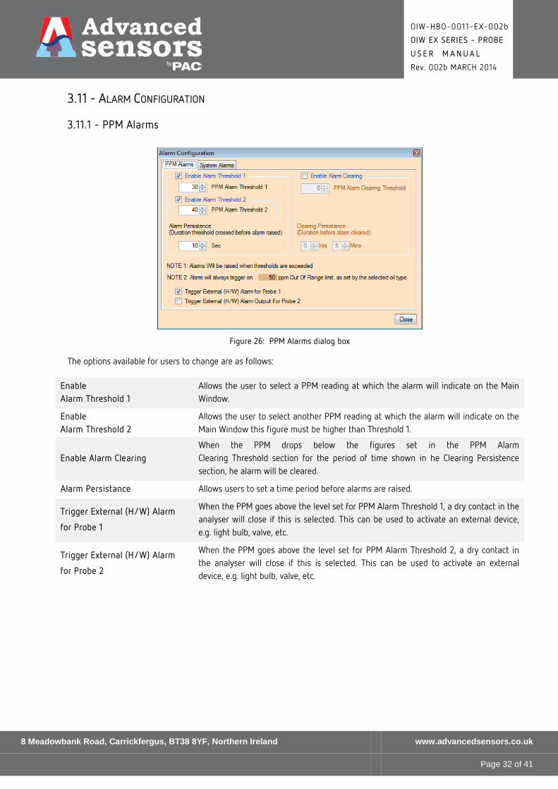
3.11 - ALARM CONFIGURATION
3.11.1 - PPM Alarms
Figure 26: PPM Alarms dialog box
The options available for users to change are as follows:
Enable Alarm Threshold 1
Allows the user to select a PPM reading at which the alarm will indicate on the Main Window.
Enable Alarm Threshold 2
Allows the user to select another PPM reading at which the alarm will indicate on the Main Window this figure must be higher than Threshold 1.
Enable Alarm Clearing When the PPM drops below the figures set in the PPM Alarm Clearing Threshold section for the period of time shown in he Clearing Persistence section, he alarm will be cleared.
Alarm Persistance Allows users to set a time period before alarms are raised.
Trigger External (H/W) Alarm
for Probe 1
When the PPM goes above the level set for PPM Alarm Threshold 1, a dry contact in the analyser will close if this is selected. This can be used to activate an external device, e.g. light bulb, valve, etc.
Trigger External (H/W) Alarm
for Probe 2
When the PPM goes above the level set for PPM Alarm Threshold 2, a dry contact in the analyser will close if this is selected. This can be used to activate an external device, e.g. light bulb, valve, etc.
8 Meadowbank Road, Carrickfergus, BT38 8YF, Northern Ireland www.advancedsensors.co.uk
Page 32 of 41

OIW-HBO-0011-EX-002b
OIW EX SERIES - PROBE
U S E R M A N U A L
Rev. 002b MARCH 2014
3.11.2 - System Alarms
Figure 27: System Alarms dialog box
The options available for users to change are as follows:
Enable System Log Alarms
Enable System Log Alarms controls whether System Alarms are registered or not. Once the Enable System Log Alarms has been checked the System Log Alarms controls become available to you to adjust.
Exclude File System Alarms
When this option is selected, any file system errors will not be created. This allows files to be moved off the system without raising alarms.
Trigger External (H/W) Alarm Output
When a system alarm is present, a dry contact in the analyser will close if this is selected. This can be used to activate an external device, e.g. light bulb, valve, etc.
8 Meadowbank Road, Carrickfergus, BT38 8YF, Northern Ireland www.advancedsensors.co.uk
Page 33 of 41
OIW-HBO-0011-EX-002b
OIW EX SERIES - PROBE
U S E R M A N U A L
Rev. 002b MARCH 2014
3.12 - 1 + 1 CONFIGURATION
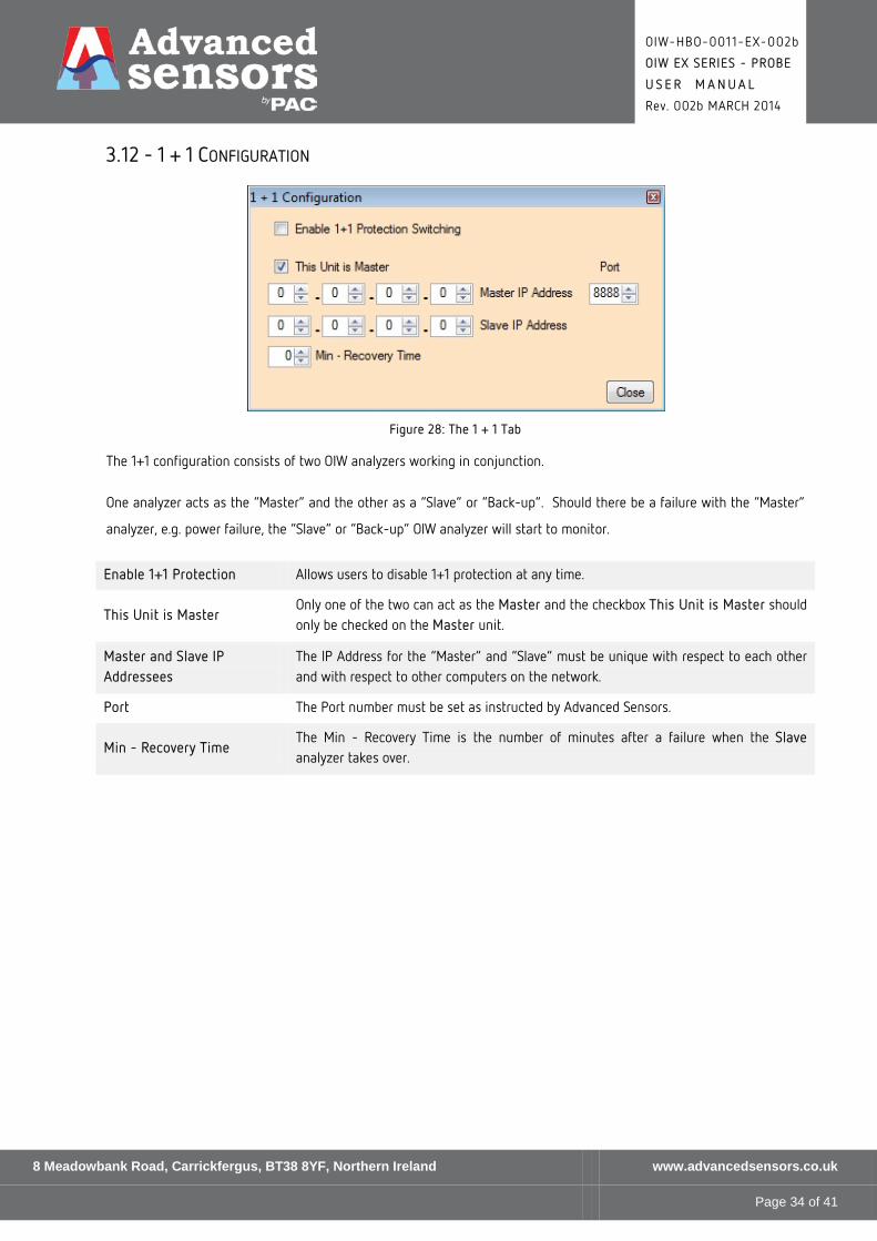
Figure 28: The 1 + 1 Tab
The 1+1 configuration consists of two OIW analyzers working in conjunction.
One analyzer acts as the “Master” and the other as a “Slave” or “Back-up”. Should there be a failure with the “Master”
analyzer, e.g. power failure, the “Slave” or “Back-up” OIW analyzer will start to monitor.
Enable 1+1 Protection Allows users to disable 1+1 protection at any time.
This Unit is Master Only one of the two can act as the Master and the checkbox This Unit is Master should only be checked on the Master unit.
Master and Slave IP Addressees
The IP Address for the “Master” and “Slave” must be unique with respect to each other and with respect to other computers on the network.
Port The Port number must be set as instructed by Advanced Sensors.
Min - Recovery Time The Min - Recovery Time is the number of minutes after a failure when the Slave analyzer takes over.
8 Meadowbank Road, Carrickfergus, BT38 8YF, Northern Ireland www.advancedsensors.co.uk
Page 34 of 41

OIW-HBO-0011-EX-002b
OIW EX SERIES - PROBE
U S E R M A N U A L
Rev. 002b MARCH 2014
3.13 - ULTRASONIC CONFIGURATION
3.13.1 - Ultrasonic Settings
This dialog box allows users to set-up certain parameters for the Ultrasonic cleaing system.
Figure 29: Ultrasonic Settings dialog box
The options are described below:
Ultrasonic Disable This allows the automatically disabling of the ultrasonics when the water temperature is at a specified threshold.
Probe Cleaning Frequency This is automatically selected by the Auto Tuning feature (see next page for details) to ensure optimum frequency for the Ultrasonics cleaning.
Cleaning Settings This allows users to fine-tune power levels and timings for the Ultrasonic cleaning cycle.
NOTE: Cleaning Settings cannot be accessed in Limited or Standard User modes.
8 Meadowbank Road, Carrickfergus, BT38 8YF, Northern Ireland www.advancedsensors.co.uk
Page 35 of 41
OIW-HBO-0011-EX-002b
OIW EX SERIES - PROBE
U S E R M A N U A L
Rev. 002b MARCH 2014
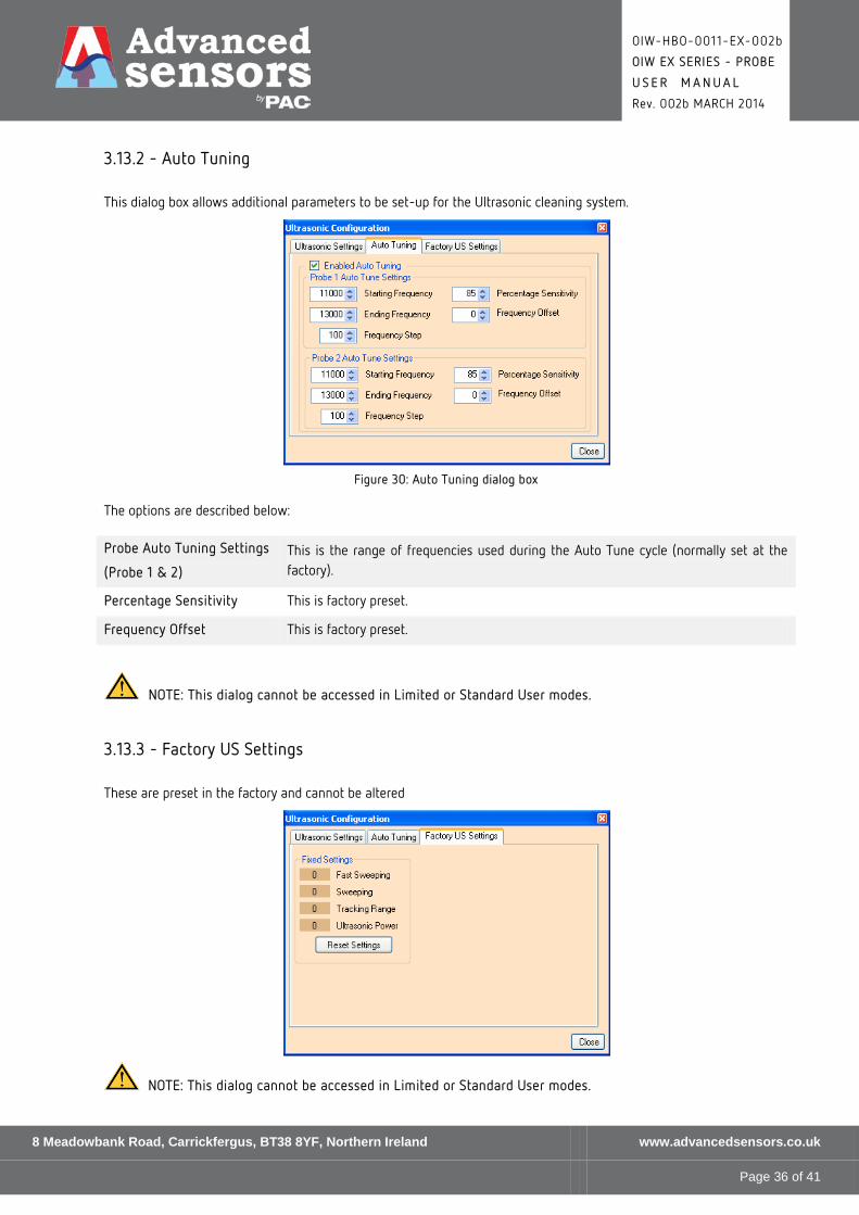
3.13.2 - Auto Tuning
This dialog box allows additional parameters to be set-up for the Ultrasonic cleaning system.
Figure 30: Auto Tuning dialog box
The options are described below:
Probe Auto Tuning Settings
(Probe 1 & 2)
This is the range of frequencies used during the Auto Tune cycle (normally set at the factory).
Percentage Sensitivity This is factory preset.
Frequency Offset This is factory preset.
NOTE: This dialog cannot be accessed in Limited or Standard User modes.
3.13.3 - Factory US Settings
These are preset in the factory and cannot be altered
NOTE: This dialog cannot be accessed in Limited or Standard User modes.
8 Meadowbank Road, Carrickfergus, BT38 8YF, Northern Ireland www.advancedsensors.co.uk
Page 36 of 41

OIW-HBO-0011-EX-002b
OIW EX SERIES - PROBE
U S E R M A N U A L
Rev. 002b MARCH 2014
3.14 - OIL TYPE CONFIGURATION
Figure 31: Oil Type Configuration(Oil Settings) window
The options are described below:
Set 1 – Set 4
(Coefficient data)
These are the coefficients that map between the Fluorescence and the PPM reading. These values are read from the Oil Type File.
Threshold Calibration curve limit values.
Load Oil Type File
This allows users to load the definition of an Oil Type from a list. Please refer to the next 2 pages for details of Oil Types Selection
The current oil type is displayed in the area at the bottom entitled Current Oil Type File.
Create New This allows you to load the definition of an Oil Type.
NOTE: For details of the Spectrometer Settings & Spectrometer Mask Settings, please refer to the Spectrometer Handbook (OIW-HBO-0005).
8 Meadowbank Road, Carrickfergus, BT38 8YF, Northern Ireland www.advancedsensors.co.uk
Page 37 of 41

OIW-HBO-0011-EX-002b
OIW EX SERIES - PROBE
U S E R M A N U A L
Rev. 002b MARCH 2014
3.14.1 - Oil Type General Information
The system measures the fluorescence of oil however, each oil source will fluoresce with varying characteristics;
consequently the system must be calibrated for each oil species. The primary characteristics of each oil type can
however be captured in a series of settings. These settings are stored within a file in a folder named OIWOilTypes on the
OIW’s hard drive.
Each oil type, and in turn each oil type file, is characterised by four main areas of data:
• Oil coefficients (not to be altered once generated by Advanced Sensors Ltd).
• Temperature coefficients.
• Offset values.
• Offset values.
These will now be described in some detail, starting with how to select an oil type (which includes the fixed oil
coefficients).
3.14.2 - Oil Type Selection
The location of the OIWOilTypes folder is at the top level of the main hard drive, is shown below. Note that the hard drive
letter may vary from system to system (in the example shown below in Figure 32 it is C :):
Figure 32: Location of OIWOilTypes directory typical on hard drive
Within this directory is a file for each of the different oil species specified. The standard library of oil species files will be
supplied by Advanced Sensors Ltd following calibration. Any oil species not in the library can be characterised and added
to the library upon supply of a customer sample
8 Meadowbank Road, Carrickfergus, BT38 8YF, Northern Ireland www.advancedsensors.co.uk
Page 38 of 41

OIW-HBO-0011-EX-002b
OIW EX SERIES - PROBE
U S E R M A N U A L
Rev. 002b MARCH 2014
Figure 33: View of OilType files
NOTE: As shown above, each oil type file is a standard Comma Separated Values (CSV) file, but neither the file name nor the contents should be altered by the user from the windows interface. If the OIW software cannot find the configured oil type file or if it cannot read it then the OIW software will log an error to the system log and shut down.
Oil Type selection is be accessed from the admin view, e.g.:
Figure 34: Admin View showing Oil Type button
Click on the Oil Type button then the Load Oil Type File button on the Oil Settings dialog box and list of all oil types on
the system should appear, e.g.:
To change the oil type simple double click on an oil type listed (or click once on the oil type name and then click the
Load button. The system is now ready to measure that type of oil.
The bottom panel will display the oil type being monitored, e.g.:
8 Meadowbank Road, Carrickfergus, BT38 8YF, Northern Ireland www.advancedsensors.co.uk
Page 39 of 41

OIW-HBO-0011-EX-002b
OIW EX SERIES - PROBE
U S E R M A N U A L
Rev. 002b MARCH 2014
3.14.3 - Integration Time Offset Control Overview
The offset value enables an offset to be applied to the PPM output. For example looking at the results in the graph
shown below in Figure 35, if the lab results are reading consistently higher than the system results then an offset can
be applied to the system output to compensate for this.
Figure 35: Offset Graph
Similarly, the fine gain can be applied if it is identified that as the fluorescence increases so does the PPM value, as
shown below in Figure 36:
Figure 36: Gain Graph
8 Meadowbank Road, Carrickfergus, BT38 8YF, Northern Ireland www.advancedsensors.co.uk
Page 40 of 41

OIW-HBO-0011-EX-002b
OIW EX SERIES - PROBE
U S E R M A N U A L
Rev. 002b MARCH 2014
3.15 - RESTORE LAST SAVED CONFIG
Clicking the Restore Last Saved Config. button highlighted below allows a user to undo all the changes made since the
last time the Save Changes & Logout button was clicked :
8 Meadowbank Road, Carrickfergus, BT38 8YF, Northern Ireland www.advancedsensors.co.uk
Page 41 of 41