User Guide Temperature Measurement Products - ABB Ltd · Temperature Measurement Products...
20
User Guide IM/TEMP Issue 1 Temperature Measurement Products Thermometers and Thermocouples
Transcript of User Guide Temperature Measurement Products - ABB Ltd · Temperature Measurement Products...

User GuideIM/TEMP Issue 1
Temperature Measurement ProductsThermometers and Thermocouples

ABBEN ISO 9001:2000
Cert. No. Q 05907
EN 29001 (ISO 9001)
Lenno, Italy – Cert. No. 9/90A
Stonehouse, U.K.
����
The Company
We are an established world force in the design and manufacture of instrumentation forindustrial process control, flow measurement, gas and liquid analysis and environmentalapplications.
As a part of ABB, a world leader in process automation technology, we offer customersapplication expertise, service and support worldwide.
We are committed to teamwork, high quality manufacturing, advanced technology andunrivalled service and support.
The quality, accuracy and performance of the Company’s products result from over 100 yearsexperience, combined with a continuous program of innovative design and development toincorporate the latest technology.
The UKAS Calibration Laboratory No. 0255 is just one of the ten flow calibration plantsoperated by the Company and is indicative of our dedication to quality and accuracy.
Information in this manual is intended only to assist our customers in the efficient operation of our equipment. Use of thismanual for any other purpose is specifically prohibited and its contents are not to be reproduced in full or part without priorapproval of the Technical Publications Department.
Health and Safety
To ensure that our products are safe and without risk to health, the following points must be noted:
1. The relevant sections of these instructions must be read carefully before proceeding.2. Warning labels on containers and packages must be observed.3. Installation, operation, maintenance and servicing must only be carried out by suitably trained personnel and in accordance with
the information given.4. Normal safety precautions must be taken to avoid the possibility of an accident occurring when operating in conditions of high
pressure and/or temperature.5. Chemicals must be stored away from heat, protected from temperature extremes and powders kept dry. Normal safe handling
procedures must be used.6. When disposing of chemicals ensure that no two chemicals are mixed.
Safety advice concerning the use of the equipment described in this manual or any relevant hazard data sheets (where applicable) may be obtained from the Company address on the back cover, together with servicing and spares information.
Temperature Measurement ProductsThermometers and Thermocouples Contents
IM/TEMP Issue 1 1
Contents
1 Safety ............................................................................................................................................... 31.1 Operator Liability ...................................................................................................................... 31.2 Personnel ................................................................................................................................ 31.3 Transport and Storage ............................................................................................................. 31.4 Electrical Installation ................................................................................................................. 3
2 Design and Function ........................................................................................................................ 42.1 General .................................................................................................................................... 42.2 Thermocouples ........................................................................................................................ 42.3 Resistance Thermometers ....................................................................................................... 42.4 Thermometer with Head-mounted Transmitter ........................................................................ 4
3 Installation ........................................................................................................................................ 53.1 Thermal Conduction Errors ...................................................................................................... 53.2 Preferred Installation Position ................................................................................................... 53.3 Cable Connections .................................................................................................................. 63.4 Ceramic Thermowells .............................................................................................................. 63.5 Thermowell Installation ............................................................................................................ 63.6 Use of Thermowells Under Changed Process Conditions ........................................................ 73.7 Thermowells with Velocity Collars ............................................................................................ 7
4 Maintenance .................................................................................................................................... 84.1 Regular Inspection ................................................................................................................... 84.2 Measurement Checking ........................................................................................................... 8
Temperature Measurement ProductsThermometers and Thermocouples Contents
2 IM/TEMP Issue 1
Appendix A Hazardous Areas ...............................................................................................................9A.1 Designation ..............................................................................................................................9A.2 Additional Ex-marking ..............................................................................................................9A.3 Range of Application ..............................................................................................................10
A.3.1 Category ......................................................................................................................10A.3.2 Groups ........................................................................................................................10A.3.3 Temperature Class ......................................................................................................10A.3.4 Special Conditions for Safe Use – Ex d Devices ...........................................................10A.3.5 Special Conditions for Safe Use – Ex n Devices ...........................................................10A.3.6 Installation ....................................................................................................................10
A.4 Assembling RTD and TC with Connection Head ....................................................................11A.4.1 Measuring Insets ..........................................................................................................11A.4.2 Cable Glands ...............................................................................................................11A.4.3 Grounding Terminals ....................................................................................................11A.4.4 Electrical Components .................................................................................................11A.4.5 Cover ...........................................................................................................................11
A.5 Assembling Field Housings AGLF, AGLFH, AGLFD and TB10 ................................................12A.5.1 Installation ....................................................................................................................12A.5.2 Cable Glands ...............................................................................................................12A.5.3 Grounding Terminals ....................................................................................................12A.5.4 Electrical Components .................................................................................................12A.5.5 Cover ...........................................................................................................................12
A.6 Dismantling ............................................................................................................................13A.7 Initial Operation ......................................................................................................................13A.8 Maintenance And Trouble Shooting .......................................................................................13A.9 Specification ..........................................................................................................................14

Temperature Measurement ProductsThermometers and Thermocouples 1 Safety
IM/TEMP Issue 1 3
1 Safety
1.1 Operator LiabilityBefore using this equipment in corrosive or abrasive environments, or with corrosive or abrasive fluids, theoperator must verify that the materials of manufacture are suitable for the application. If requested, ABB willassist in this assessment but will not accept liability for the selection of materials.
Operators must observe all applicable national and plant regulations with regard to installation, testing andrepair of this equipment.
1.2 PersonnelThis equipment must be installed, commissioned and maintained by trained personnel who are authorizedby the plant operator. These personnel must have read and understood this manual and must comply withits instructions.
1.3 Transport and StorageCare must be taken during transportation of the device to ensure that it is not damaged. Special care mustbe taken to avoid excessive vibration and physical shock.
The equipment must not be transported or stored in such a way that it becomes contaminated by moistureor other potentially damaging contaminants.
Check the equipment thoroughly after transportation and storage and before installation. Any damage mustbe reported to the supplier or the shipper before installation.
1.4 Electrical InstallationElectrical installation must be performed only by authorized and competent personnel. Careful observationof the electrical connection information supplied in this manual is required before commencing installation.

Temperature Measurement ProductsThermometers and Thermocouples 2 Design and Function
4 IM/TEMP Issue 1
2 Design and Function
2.1 GeneralABB supply complete thermometer assemblies ready for immediate installation into the plant. ABB alsosupply spare parts and temperature accessories.
On receipt of a thermometer assembly, unpack it and check that all the ordered items and documentationare available before installation.
Take care to ensure that thermometer assembly is not damaged by rough or careless handling.
2.2 ThermocouplesWhere thermocouples are supplied without a local transmitter, the thermocouple and the measuring circuitmust be connected using suitable compensating cable. This cable must be of the correct type for thethermocouple and be connected with the correct polarity.
Route cables at least 500 mm (19.7 in.) away from power cables, preferably in a specifically designatedsignal tray. Twisted and shielded cables prevent unwanted signal interference.
Thermocouple signals may be isolated or the negative pole may be earthed at the measurement end. It isimportant to know which of these is the case when considering the likelihood of earth loops in the signalsystem. Typically, thermocouple systems are supplied isolated unless an earthed system is requested.
2.3 Resistance ThermometersWhere a resistance thermometer is supplied without a local transmitter, the thermometer and themeasuring circuit must be connected using standard instrumentation cable of no less than 1.5 mm2
(0.06 in2). Use a 4-wire circuit to eliminate the resistive effects of the connecting cables. Where a 4-wirecircuit is impractical, a 3-wire circuit may be used with some (unpredictable) degradation in systemaccuracy.
Route cables at least 500 mm (19.7 in.) away from power cables, preferably in a specifically designatedsignal tray. Twisted and shielded cables prevent unwanted signal interference.
Ensure that the circuit current is kept as low as possible (typically 0.1 to 1 mA) to prevent self heating of thesystem.
2.4 Thermometer with Head-mounted TransmitterMany of the potential problems detailed above can be avoided by using a head-mounted transmitter. Thisdevice converts the raw temperature signal into an industry-standard plant instrumentation signal as closeto the point of measurement as is practically possible. Observe the following precautions when using thesesystems.
Head temperature must not exceed the maximum operating temperature for the transmitter.
Supply voltage must be within the limits specified for the transmitter.
Output signal protection must be in accordance with the industry and plant standards for the signaltype.
Temperature Measurement ProductsThermometers and Thermocouples 3 Installation
IM/TEMP Issue 1 5
3 Installation
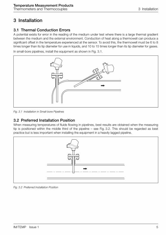
3.1 Thermal Conduction ErrorsA potential exists for error in the reading of the medium under test where there is a large thermal gradientbetween the medium and the external environment. Conduction of heat along a thermowell can produce asignificant offset in the temperature experienced at the sensor. To avoid this, the thermowell must be 6 to 8times longer than its tip diameter for use in liquids, and 10 to 15 times longer than its tip diameter for gases.
In small-bore pipelines, install the equipment as shown in Fig. 3.1.
3.2 Preferred Installation PositionWhen measuring temperatures of fluids flowing in pipelines, best results are obtained when the measuringtip is positioned within the middle third of the pipeline – see Fig. 3.2. This should be regarded as bestpractice but is less important when installing the equipment in a heavily lagged pipeline.
Fig. 3.1 Installation in Small-bore Pipelines
Fig. 3.2 Preferred Installation Position
Temperature Measurement ProductsThermometers and Thermocouples 3 Installation
6 IM/TEMP Issue 1
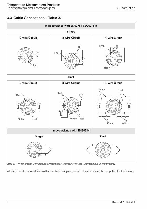
3.3 Cable Connections – Table 3.1
Where a head-mounted transmitter has been supplied, refer to the documentation supplied for that device.
In accordance with EN60751 (IEC60751)
Single
2-wire Circuit 3-wire Circuit 4-wire Circuit
Dual
2-wire Circuit 3-wire Circuit 4-wire Circuit
In accordance with EN60584
Single Dual
Table 3.1 Thermometer Connections for Resistance Thermometers and Thermocouple Thermometers.
Red
Red
Red
Red
Red
Black
RedYellow
Black
RedYellow
Black
Yellow Red
White
�
�
�
��
�
Temperature Measurement ProductsThermometers and Thermocouples 3 Installation
IM/TEMP Issue 1 7
3.4 Ceramic ThermowellsWhere a ceramic thermowell has been supplied for high temperature service, take special care to protect itfrom physical and thermal shock.
3.5 Thermowell Installation To prevent failure of the seal and leakage of process fluid when fitting thermowells to the plant, it isimportant to ensure that the correct nuts, bolts, studs and gaskets are used and that threads are tightenedappropriately.
3.6 Use of Thermowells Under Changed Process ConditionsWhere an existing thermowell is to be used in a modified process or process conditions, take care toensure that it is still suitable for the new service. Pay particular attention to the following:
Corrosion and erosion resistance
Temperature limitations
Process connection rating and condition
Wake frequency
3.7 Thermowells with Velocity CollarsVelocity collars are used to shorten the unsupported length of the stem of a thermowell, thus changing itsresonance frequency. To ensure the correct operation of a thermowell fitted with a velocity collar, a good fitbetween the collar and the wall of the fitting is essential. Therefore, machining of the standoff to achieve atight sliding fit between the standoff wall and the velocity collar is required. Contact ABB for advice if thereare any doubts regarding acceptable tolerances.

Temperature Measurement ProductsThermometers and Thermocouples 4 Maintenance
8 IM/TEMP Issue 1
4 Maintenance
4.1 Regular InspectionInspect the equipment regularly for signs of wear and leakage. Electrical connections must be inspected forcorrosion and loosening of connections due to vibration. External protection housings must be inspectedfor signs of corrosion that could lead to leakage.
4.2 Measurement CheckingThe best way to check the accuracy of a thermometer system is to remove it from service and check itsoperation in a calibration laboratory. If this is not possible, use a hand-held laboratory device to check thetemperature seen by the thermometer system in situ.
Use plant standard signal sources to check the signal path from the thermometer to the rest of the plant.
Where a signal appears to operate correctly at the sensor but gives a false reading at the measuringsystem, ensure that no ground loops exist. Ground loops are eliminated either by completely isolating thesystem from ground or by ensuring that it is grounded in one place only.
Where an error occurs at installation or re-installation, ensure that the polarity and cable type are correct forthe installation.
Where an error occurs over time during operation, check for ingress of moisture and/or other contaminantsand check the mechanical state of cable connections.
Temperature Measurement ProductsThermometers and Thermocouples Appendix A Hazardous Areas
IM/TEMP Issue 1 9
Appendix A Hazardous AreasThis Appendix contains important safety information regarding thermometers and thermocouples designedfor use in hazardous areas according to EU-directive 94/9 EC (ATEX 100a).
A.1 DesignationEx d
– Resistance temperature detectors (RTD) and thermocouples (TC) provided with AG Seriesconnection heads.
– AG Series field housings.
Ex n
– Resistance temperature detectors (RTD) and thermocouples (TC) provided with connectionheads.
– Field housings.
A.2 Additional Ex MarkingRTD and TC with appropriate thermowells or protection tubes for temperature measurement within group IIcategory 2 (Ex d) or group II category 3 (Ex n).
Other RTD and TC as well as field housings.
Temperature Measurement ProductsThermometers and Thermocouples Appendix A Hazardous Areas
10 IM/TEMP Issue 1
A.3 Range of Application
A.3.1 CategorySeries Ex d RTD, TC and field housings are devices of group II, category 2 as defined by EU directive94/9/EC (ATEX 100a).
Series EEx de RTD, TC and field housings are devices of group II, category 2 as defined by EU directive94/9/EC (ATEX 100a).
Series Ex n RTD, TC and field housings are devices of group II, category 3 as defined by EU directive94/9/EC (ATEX 100a.).
A.3.2 GroupsEx d devices are certified Baseefa 04 ATEX 0033X for use in potentially explosive atmospheres of group IIas defined by EN 50014:1997 and EN 50018:1994.
EEx de devices are certified Baseefa 03 ATEX 0124X for use in potentially explosive atmospheres of groupII as defined by EN 50014:1997 and EN 50018:1994.
Ex n devices are certified Baseefa 03 ATEX 0126X for use in potentially explosive atmospheres of group IIas defined by EN 50021:1999.
A.3.3 Temperature ClassEX d and Ex n devices are marked with temperature class T6. Higher operating temperatures are possiblein case of potentially explosive and atmospheres permissible for temperature class T5 or T4. Operatingtemperatures are defined in Appendix A.9.
EEx de devices are marked with temperature class T6 and for use in ambient temperatures between –20and 40 °C (–4 and 104 °F).
TR04, TS02, TR01 And TH02 transmitters are certified for use in temperature classes up to T1 only, wherethis does not affect the temperature rating of other components.
A.3.4 Special Conditions for Safe Use – Ex d DevicesAll connection heads suffixed /G must be provided with an internal earth.
A.3.5 Special Conditions for Safe Use – Ex n DevicesAll replacement RTD and TC temperature insets must be fitted with transient voltage suppression devicesof the type P6KE-30A or equivalent, with a maximum breakdown voltage of 31.5 V and a peak pulsecurrent rating of 9.0 A minimum at 85 °C (185 °F).
Connection heads types HYP and H9 must be protected from exposure to ultra violet light.
A.3.6 InstallationThe general requirements for planning, selection and installation of electrical equipment within potentiallyexplosive atmospheres detailed in EN 60079-14 must be complied with.

Temperature Measurement ProductsThermometers and Thermocouples Appendix A Hazardous Areas
IM/TEMP Issue 1 11
A.4 Assembling RTD and TC with Connection HeadFor thermowells or protection and extension tubes to be installed in category 2 or 3 applications:
1. Assemble appropriate Thermowells or protection tubes for the separation of zones.
2. Use seals with appropriate temperature, pressure and corrosion resistance as necessary.
3. Prevent raising of temperature due to heat flow or heat accumulation (for example, by allowingsufficient distance between the RTD/TC and hotter components, by fitting thermal insulation or byenabling heat dissipation by allowing sufficient air circulation).
A.4.1 Measuring InsetsUse only approved ABB measuring insets with appropriate diameter for the corresponding bore of theconnection head.
A.4.2 Cable GlandsUse only approved cable glands of the correct protection type:
Observe certification and installation instructions of the cable glands.
Check threads for damage and apply a suitable threadlocking compound (for example, Loctite 273)before fitting.
Ensure cable to be used is suitable (correct type, outside diameter, etc.).
Tighten cable gland until the cable is secured firmly and sealed by the sealing ring. Do notovertighten.
Use suitable installation measures to protect cable against mechanical loads (tension, torsion, etc.).
Blank-off all unused cable entry holes with certified plugs.
A.4.3 Grounding TerminalsAdditional grounding connections are not required in the case of a reliable electrical contact to groundedconductive tubing systems or other grounded conductive supporting systems (for example, via a metallicmounting plate).
A.4.4 Electrical ComponentsAssemble electrical components with assembling sets (if required).
Connect electrical components according to the relevant operating instructions.
A.4.5 CoverCheck threads for damage and screw the cover on by hand until the O-ring seal is compressed. Secure thecover with the locking screw.
Note. The use of threadlocking compound is not necessary on NPT threads.
Note. Do not use tools to tighten the cover. Hexagons and recesses are opening aids only.
Temperature Measurement ProductsThermometers and Thermocouples Appendix A Hazardous Areas
12 IM/TEMP Issue 1
A.5 Assembling Field Housings AGLF, AGLFH, AGLFD and TB10
A.5.1 InstallationInstall field housings permanently to fixed walls, supports or pipework.
A.5.2 Cable GlandsUse only approved cable glands of the proper protection type:
Observe certification and installation instructions of the cable glands.
Check threads for damage and apply a suitable threadlocking compound (for example, Loctite 273)before fitting.
Ensure cable to be used is suitable (correct type, outside diameter, etc.).
Tighten cable gland until the cable is secured firmly and sealed by the sealing ring. Do notovertighten.
Use suitable installation measures to protect cable against mechanical loads (tension, torsion, etc.).
Blank-off all unused cable entry holes with certified plugs.
A.5.3 Grounding TerminalsAdditional grounding connections are not required in the case of a reliable electrical contact to groundedconductive tubing systems or other grounded conductive supporting systems (e.g. via a metallic mountingplate).
A.5.4 Electrical ComponentsAssemble electrical components with assembling sets (if required)
Connect electrical components according to the relevant operating instructions
A.5.5 CoverCheck threads for damage and screw the cover on by hand until the O-ring seal is compressed. Secure thecover with the locking screw.
Note. The use of threadlocking compound is not necessary on NPT threads.
Note. Do not use tools to tighten the cover. Hexagons and recesses are opening aids only.
Temperature Measurement ProductsThermometers and Thermocouples Appendix A Hazardous Areas
IM/TEMP Issue 1 13
A.6 DismantlingDo not open cover when electrical circuits are energized. Allow sufficient time for discharge and coolingbefore opening cover (this depends on operating conditions, malfunction, etc.).
A.7 Initial OperationBefore initial operation, ensure that:
Thermowells and protection tubes are assembled correctly and secure.
All required components at the connection head or field housing according to all requirementsrelevant for hazardous area protection (measuring inset, cable gland, cable, cover, etc.) areassembled correctly and secure.
Grounding terminal is correctly connected (if required).
A.8 Maintenance And Trouble ShootingThe following measures ensure correct operation of the RTD/TC
Check enclosures, cables, cable glands, grounding connections, etc. for damage and wear in aregular manner, depending on expected operation stresses.
Replace damaged or worn components with approved ABB spare parts only (especially insets,transmitters, displays and seals).
Do not carry out any unauthorized repair work on any part of the flameproof enclosure.
Check pressure-loaded components (thermowells, protection tubes, flanges etc.) during routinepressure testing.
Warning. Disconnect and stop operation immediately if any defect is found that compromisesany flameproof relevant feature (for example, enclosure, cable, cable glands, groundingconnections, etc.). Do not start operation until safe operating conditions are restored.

Temperature Measurement ProductsThermometers and Thermocouples Appendix A Hazardous Areas
14 IM/TEMP Issue 1
A.9 Specification
Electrical power limitations
Ex d measuring inset with transmitter
EEx de devices
Ex n transmitter with or without indicator
Ex d and Ex n measuring inset without transmitter
Max. supply voltage 29.4 V DC
Max. thermal / electrical power Pmax determined according to Table A.1, page 15(overall power consumption of all electrical components)
Max. supply current I max = P max / V max
Fuse rated current ≤I max / 1.7
Max. number of transmitters per assembly 2
Max. supply voltage 4 V DC
Max. RTD measuring current <2 mA per sensor element
Max. TC output voltage <100 mV per sensor element
Max. supply voltage 29.4 V DC
Max. thermal / electrical power Pmax determined according to Table A.1 page 15(overall power consumption of all electrical components)
Max. supply current I max = P max / V max
Fuse rated current ≤I max / 1.7
Max. number of transmitters per assembly 4
Max. supply voltage 10 V DC
Max. RTD measuring current <2 mA per sensor element
Max. TC output voltage <100 mV per sensor element
Max. supply current I max = P max / V max
Max. number of transmitters per assembly (Ex n Only) 4

Temperature Measurement ProductsThermometers and Thermocouples Appendix A Hazardous Areas
IM/TEMP Issue 1 15
Operating temperature range
Ex d RTDs and TCs
Ex n RTDs and TCs
Ex d Field Housings AGLF, AGLFH, AGLFD, AGSF, AGSFD, AGSFH within Category 2
Min. operating temperature –35 °C (–31 °F)
Max. operating temperature (connection heads AGL, AGS, AGLH, AGH, AGLHD, AGFHD, AGSH within Category 2)
See Table A.1
Extension tube within Category 2 See Table A.1
Min. operating temperature –20 °C (–4 °F)
Max. operating temperature (connection heads AGL, AGS, AGLH, AGH, AGLHD, AGFHD, AGSH, KNE, HYP, KI, H3, H4, H6 and H9 within Category 3
See Table A.1
Extension tube within Category 3 See Table A.1
Min. operating temperature –35 °C (–31 °F)
Max. operating temperature See Table A.2
Maximum Ambient Temperature – °C (°F)
Max Power (W) 0 (0 TX) 2 (1 TX) 4 (2 TX) 6 (3 TX) 8 (4 TX)
T4 95 (203) 95 (203) 89 (192) 83 (181) 79 (174)
T5 95 (203) 91 (196) 86 (187) 81 (178) 77 (171)
T6 80 (176) 76 (169) 71 (160) 66 (151) 62 (144)
Table A.1 Maximum Permissible Operating Temperatures of Connection Heads (including extension tubes, thermowells, protection tubes, assembling sets etc. with direct thermal contact).
Maximum Ambient Temperature – °C (°F)
Max Power (W) 0 (0 TX) 2 (1 TX) 4 (2 TX) 6 (3 TX) 8 (4 TX)
T4 130 (266) 126 (259) 121 (250) 116 (241) 112 (234)
T5 95 (203) 91 (196) 86 (187) 81 (178) 77 (171)
T6 80 (176) 76 (169) 71 (160) 66 (151) 62 (144)
Table A.2 Maximum Permissible Operating Temperatures of Field Housings (including extension tubes, thermowells, protection tubes, assembling sets etc. with direct thermal contact).

Temperature Measurement ProductsThermometers and Thermocouples Appendix A Hazardous Areas
16 IM/TEMP Issue 1
Ex n Field Housings AGLF, AGLFH, AGLFD, AGSF, AGSFD, AGSFH and TB Series (10–14) within zone 2
Temperature measurementUse appropriate thermowells or protection tubes for temperature measuring within category 2 for Ex d devices andwithin category 3 for Ex n devices.
Physical Requirements
Minimum bend radius (EEx de devices only)6 x stem diameter
or
4 x stem diameter provided bending is accomplished over a mandrel in one set without straightening.
Minimum wall thickness3 mm in the case of thermowells or protection tubes made of stainless steel (according to DIN 17440) or made ofnon-corrosive nickel alloys (according to DIN 17742).
3 mm in the case of thermowells or protection tubes made of other steels.
DesignSpecified material and dimensions of thermowells and protection tubes must be sufficient to resist permanently alloperating loads with sufficient safety margins (temperature, pressure, flow-induced bending stress and vibration,corrosion etc.).
TestingThermowells and protection tubes must be pressure tested at 1.5 times the nominal pressure.
Min. operating temperature –20 °C (–4 °F)
Max. operating temperature See Table A.3
Max Power (W) 2 (1 TX) 4 (2 TX) 6 (3 TX) 8 (4 TX)
Resulting temperature rise (°K) (including 5 °K safety margin) 12 19 26 33
Temperature Class T6 limit – °C (°F) 73 (163) 66 (151) 59 (138) 52 (126)
Table A.3 Maximum Permissible Operating Temperatures of Connection Heads and Field Housings (Including ExtensionTubes, Thermowells, Protection Tubes, Assembling Sets etc. With Direct Thermal Contact).

PRODUCTS & CUSTOMER SUPPORTProducts
Automation Systems• for the following industries:
– Chemical & Pharmaceutical– Food & Beverage– Manufacturing– Metals and Minerals– Oil, Gas & Petrochemical– Pulp and Paper
Drives and Motors• AC and DC Drives, AC and DC Machines, AC
Motors to 1kV• Drive Systems• Force Measurement• Servo Drives
Controllers & Recorders• Single and Multi-loop Controllers• Circular Chart and Strip Chart Recorders• Paperless Recorders• Process Indicators
Flexible Automation• Industrial Robots and Robot Systems
Flow Measurement• Electromagnetic Flowmeters• Mass Flowmeters• Turbine Flowmeters• Wedge Flow Elements
Marine Systems & Turbochargers• Electrical Systems• Marine Equipment• Offshore Retrofit and Refurbishment
Process Analytics• Process Gas Analysis• Systems Integration
Transmitters• Pressure• Temperature• Level• Interface Modules
Valves, Actuators and Positioners• Control Valves• Actuators• Positioners
Water, Gas & Industrial Analytics Instrumentation
• pH, Conductivity and Dissolved Oxygen Transmitters and Sensors
• Ammonia, Nitrate, Phosphate, Silica, Sodium, Chloride, Fluoride, Dissolved Oxygen and Hydrazine Analyzers
• Zirconia Oxygen Analyzers, Katharometers, Hydrogen Purity and Purge-gas Monitors, Thermal Conductivity
Customer Support
We provide a comprehensive after sales service via aWorldwide Service Organization. Contact one of thefollowing offices for details on your nearest Service andRepair Centre.
United KingdomABB LimitedTel: +44 (0)1946 830 611Fax: +44 (0)1946 832 661
United States of AmericaABB Inc.Tel: +1 215 674 6000Fax: +1 215 674 7183
Client WarrantyPrior to installation, the equipment referred to in thismanual must be stored in a clean, dry environment, inaccordance with the Company's publishedspecification.
Periodic checks must be made on the equipment'scondition. In the event of a failure under warranty, thefollowing documentation must be provided assubstantiation:
1. A listing evidencing process operation and alarm logs at time of failure.
2. Copies of all storage, installation, operating and maintenance records relating to the alleged faulty unit.

IM/T
EM
PIs
sue
1
ABB has Sales & Customer Support expertisein over 100 countries worldwide
www.abb.com
The Company’s policy is one of continuous product improvement and the right is reserved to modify the
information contained herein without notice.
Printed in UK (02.09)
© ABB 2009
ABB LimitedSalterbeck Trading EstateWorkington, CumbriaCA14 5DSUKTel: +44 (0)1946 830 611Fax: +44 (0)1946 832 661
ABB Inc.125 E. County Line RoadWarminsterPA 18974USATel: +1 215 674 6000Fax: +1 215 674 7183