Measurement & Analytics | Measurement made easy Temperature measurement...
153
Temperature measurement solutions Precision and flexibility in temperature measurement for process efficiency Measurement & Analytics | Measurement made easy
Transcript of Measurement & Analytics | Measurement made easy Temperature measurement...
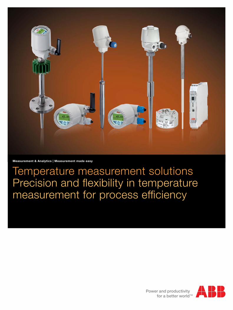
Temperature measurement solutionsPrecision and fl exibility in temperaturemeasurement for process effi ciency
Measurement & Analytics | Measurement made easy

Expertise in technology More than a century of experience
To operate any process efficiently, it is essential to measure, actuate, record and control. With ABB’s measurement and analytical products and solutions, you are receiving the best technology combined with the most reliable products available on the market.
ABB offers a broad range of life cycle services for optimum product performance. A global network of specialists delivers local service and support.
Research and development is a vital source of ABB’s technology leadership. It builds on the foundation of existing technologies for new applications, and continues to develop the breakthrough technologies needed to meet the challenges of the future.
ABB and its heritage companies have been leaders in innovation and technology for more than 100 years.
Aztec
Pressductor®
Bush Beach EngineeringLimited
2 | Temperature measurement solutions

1 Water and waste water | 2 Power and industrial steam | 3 Chemical and petrochemical | 4 Oil and gas | 5 Pulp and paper | 6 Minerals | 7 Metals
8 Food and beverage | 9 Marine
1
4
7
2
5
8
3
6
9
Comprehensive measurement solutionsServing your industry
ABB‘s product portfolio:
− Analytical measurement
− Flow measurement
− Natural gas measurement
− Actuators and positioners
− Pressure measurement
− Temperature measurement
− Recorders and controllers
− Level measurement
− Device management
− Force measurement
− Service
ABB measurement and analytical products provide world-class
solutions for any industry, utility or municipality. Innovations
deliver technological solutions to make it easier for you to run
your plants. ABB’s measurement and analytical products are
based on common technology, providing a common look and
feel and method of operation. This results in products, that
are easy to configure, easy to integrate, and easy to maintain.
For more information please visit: www.abb.com/measurement
Temperature measurement solutions | 3

Global access and availabilityA partner to rely on
ABB service: available wherever you are
Wherever you are, whatever you need – you can rely on ABB service
Information whenever you need it – Device management, fieldbus and wireless
ABB’s vast base of globally installed products and systems is
coupled with technical and process expertise, backed up by
a broad scope of services that lay the foundation for end-to-
end support for your enterprise. ABB’s automated monitoring
and reporting products are simple and accurate, so critical
information is always readily accessible.
ABB’s measurement and analytical products feature the latest
in onboard diagnostics and intelligence to help you run your
business more effectively. ABB gives you the choice to decide
which communication protocols you would like to use to
access this information. You can select from a family of tools
and from different ways to manage the lifecycle of the devices
in order to get the most out of your investment.
ABB’s full scope of measurement and analytical products
services cover everything from start-up and commissioning
through to lifecycle support, giving you all you need to maximize
the accuracy and reliability of your assets. The global strength
of ABB means that service and support are available wherever
and whenever help is needed.
ABB’s device management product range includes
− Fieldbus and wireless solutions
− Mobility handhelds
− Asset vision software
− Scalable service management
ABB’s wireless measurement: truly autonomous with Energy Harvester
4 | Temperature measurement solutions

Temperature measurement solutionsOffering precision and flexibility
Temperature measurement in an Oil and Gas application
Precise temperature measurement is fundamental for successful process operations in a variety of industries. Customers benefit from ABB’s extensive experience in the field of temperature measurement, yielding one of the most comprehensive product portfolios on the market. ABB provides the support needed to choose the device or system that perfectly suits your process requirements. A full range of reliable temperature measurement products tailored to serve special industry applications is available from ABB.
With innovative temperature sensors and transmitters from
ABB, you benefit from low investment costs and standardized
modules with impressive long-term stability. The versatile
family of temperature measurement products is based on a
modular design principle allowing for the utmost flexibility.
ABB offers extremely short delivery times for its standard
versions and a simple ordering process due to the clear
portfolio structure.
High-temperature measurement for up to 1800 °C (3272 °F) solutions
Temperature measurement solutions | 5

SensyTemp temperature sensorsPortfolio overview
Process measurement
SensyTemp TSP series sensors allow for measuring inset
replacement during operation. With their short response time
and high vibration resistance these devices meet the most
demanding process requirements.
High-temperature measurement
SensyTemp TSH series temperature sensors have been
designed to meet the requirements of temperature applications
from 600 °C to 1800 °C (1112 °F to 3272 °F). ABB assists
customers in selecting the appropriate thermowell for demanding
high-temperature measurements in combustion, annealing or
smelting processes.
Process measurement High-temperature measurement
Product series SensyTemp TSP100 and TSP300 SensyTemp TSH200
Applications – Oil and gas industry – Power generation
– Petrochemical industry – Metals processing
– Chemical industry – Cement industry
– Power generation – Glass industry
– Process industry – Garbage incineration
– Plant construction – Basic industry
Process connections – Insertion in an existing thermowell – Threaded socket
– Thermowells with cylindrical or – Stop flange with counterflange
conical thread connections – Welded standard flange
– Thermowells with flanges in acc. with – Ceramic thermowell
international standards – Metal thermowell
Measuring ranges – Resistance thermometers: Thermocouples up to 1800 °C (3272 °F)
-196…600 °C (-320.8…1112 °F)
– Thermocouples:
-40…1100 °C (-40…2012 °F)
Functional safety SIL2 in accordance with IEC 61508
Approvals for explosion protection IECEx, ATEX, GOST,
Other approvals are pending
Data sheet DS/TSP1xx, DS/TSP3xx DS/TSH2xx
6 | Temperature measurement solutions

Temperature sensorsComponents
1. Connection head
Connection heads of temperature sensors comply with
EN 50446. This industry standard defines the electrical and
mechanical connection conditions for the thermowell,
measuring inset or transmitter and the connection cable.
For decades, ABB has continuously advanced the connection
head design for one and two transmitters.
2. Extension tube
The extension tube protects the electronics from high process
temperatures. When process lagging is used, the extension
tube enables accessibility of the connections above the lagging.
3. Process connection
Measuring elements can be connected directly into the
process using compression fittings. When a thermowell is
used it can be connected to the process via a screwed
connector or a flange to any of a number of international
standards. Additionally a thermowell may also be provided
in a design suitable for welding into position.
4. Thermowell
A fabricated thermowell consists of a seamless pipe sealed
at the process end with a welded piece. A solid drilled
thermowell is manufactured from a single piece of bar material
with a hole drilled to within a few millimeters of the tip. Both of
these thermowell types provide protection for the temperature
sensor.
(a) Measuring inset
The measuring inset protects the temperature sensor and
increases measuring accuracy. The measuring inset can be
replaced at any time while the system is running, without
opening the process or shutting down the plant. This allows
for easy calibration of the measuring inset.
(a) 1.
2.
3.
4.
Temperature measurement solutions | 7

Product series TSP111 TSP121 TSP131
Process connections – Without thermowell – With welded tubular thermowell – With drilled barstock thermowell
- Insertion in an existing - Screw-in thread - Screw-in thread
thermowell - Flange - Flange
- Compression fitting - Weld-in socket
Modular design – Flexible
- Measuring inset, thermowell, extension tube, connection head, transmitter
- Interchangeable measuring inset
– Connection heads
- BUZ: Aluminum, with hinged cover
- BUZH: Aluminum, with upper hinged cover
- BUZHD: Aluminum, with upper hinged cover and LCD indicator type AS
- BUKH: Plastic, with upper hinged cover
- Other heads in various designs and materials
– Transmitter in connection head (4...20 mA HART, FF, PA)
– Suited to explosion protection, intrinsic safety
Measuring ranges – Resistance thermometers: -196...600 °C (-320.8…1112 °F)
– Thermocouples: -40...1100 °C (-40…2012 °F)
Measuring insets In accordance with DIN 43735, replaceable
Display (optional) Transmitter-controlled graphic (alphanumeric) LCD indicator type AS
for process-, sensor- or current-value display
Functional safety SIL2 in accordance with IEC 61508
Approvals for explosion protection IECEx, ATEX, GOST, other approvals are pending
Connection heads
Data sheet DS/TSP1x1
SensyTemp TSP series 100 Advanced sensors for the process industry
BUZ BUZH BUZHD BUKH
Display type AS
8 | Temperature measurement solutions

AGL AGLH AGLD AGS AGSH AGSD
Display Display
type A / AS type A / AS
Product series TSP311 TSP321 TSP331
Process connections – Without thermowell – With welded tubular thermowell – With drilled barstock thermowell
- Insertion in an existing - Screw-in thread - Screw-in thread
thermowell - Flange - Flange
- Compression fitting - Weld-in socket
Modular design – Sturdy and versatile
- Measuring inset, thermowell, extension tube, connection head, transmitter
- Interchangeable measuring inset
– Connection heads
- AGL: Aluminum, with screw-on cover
- AGLH: Aluminum, with upper screw-on cover
- AGLD: Aluminum, with screw-on cover and LCD indicator type A / AS
- AGS: Stainless steel, with screw-on cover
- AGSH: Stainless steel, with upper screw-on cover
- AGSD: Stainless steel, with screw-on cover and LCD indicator type A / AS
– Transmitter in connection head (4...20 mA HART, FF, PA)
– Suited to explosion protection, intrinsic safety and flameproof enclosure
Measuring ranges – Resistance thermometers: -196...600 °C (-320.8…1112 °F)
– Thermocouples: -40...1100 °C (-40…2012 °F)
Measuring insets In accordance with DIN 43735, replaceable
Display (optional) Transmitter-controlled graphic (alphanumeric) LCD indicator type A / AS with dual function
– Transmitter confi guration via button (HMI)
– Process-, sensor- or current value display
Functional safety SIL2 in accordance with IEC 61508
Approvals for explosion protection IECEx, ATEX, FM, CSA, GOST, other approvals are pending
Connection heads
Data sheet DS/TSP3x1
SensyTemp TSP series 300 Meeting most demanding requirements
Temperature measurement solutions | 9
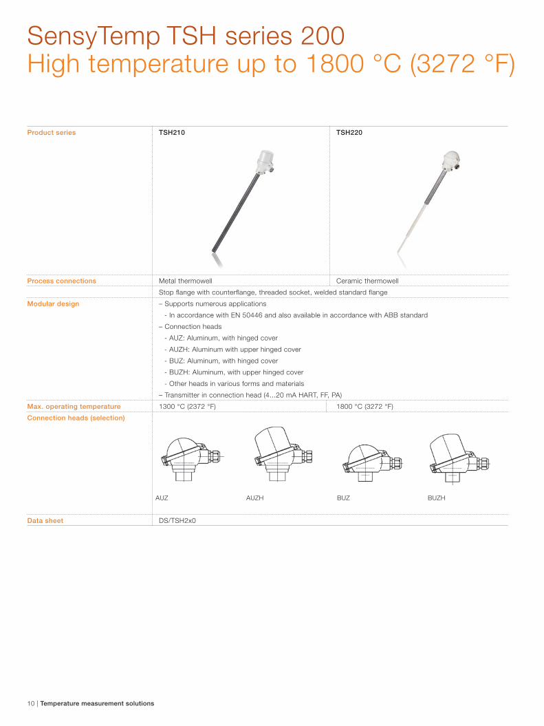
SensyTemp TSH series 200High temperature up to 1800 °C (3272 °F)
Product series TSH210 TSH220
Process connections Metal thermowell Ceramic thermowell
Stop flange with counterflange, threaded socket, welded standard flange
Modular design – Supports numerous applications
- In accordance with EN 50446 and also available in accordance with ABB standard
– Connection heads
- AUZ: Aluminum, with hinged cover
- AUZH: Aluminum with upper hinged cover
- BUZ: Aluminum, with hinged cover
- BUZH: Aluminum, with upper hinged cover
- Other heads in various forms and materials
– Transmitter in connection head (4...20 mA HART, FF, PA)
Max. operating temperature 1300 °C (2372 °F) 1800 °C (3272 °F)
Connection heads (selection)
Data sheet DS/TSH2x0
AUZ AUZH BUZ BUZH
10 | Temperature measurement solutions

Wireless made easy Truly autonomous with Energy Harvester
Product series TSP3xx-W TSP3xx-W TTF3xx-W
Communication protocol WirelessHART WirelessHART WirelessHART
Device type Battery supply without Battery supply with Battery supply without
Energy Harvester Energy Harvester Energy Harvester
Input – Two sensors inputs
- Resistance thermometers, resistance-type remote sensor (0…5000 Ohm)
- Thermocouples, voltages, mV voltages (-125…1100 mV)
Sensor connection – Pt100 2-, 3-, 4 wire, thermocouple with internal reference junction
– 2x Pt100 2- and 3 wire, 2x thermocouple or 1x Pt100 2-, 3-, 4 wire and
1x thermocouple
Technical features – Continuous sensor monitoring and self-monitoring
- Supply voltage, wire break and corrosion monitoring
– Sensor error adjustment
– Electrical isolation
– Specific linearization
- Callendar-Van Dusen coefficients, table of value pairs / 32 points
– Innovative energy management
Indicator (optional) Transmitter-controlled graphic (alphanumeric) LCD indicator type B with dual function:
– Transmitter confi guration via push button
– Process-, sensor- or current-value display
Confi guration Via HART handheld (DTM, EDD, HMI)
Approvals for explosion protection IECEx, ATEX, other approvals are pending
Data sheet DS/TSP3x1-W DS/TTF300-W
The WirelessHART temperature sensor TSP300-W with Energy Harvester is the world’s first self-powered wireless measurement devices requiring no wiring, no external power supply and ideally no battery replacement.
Temperature measurement solutions | 11

Oil and gas temperature measurement Safe tough and reliable
Temperature measurement systems for the oil and gas
industry are engineered, manufactured and documented
by ABB engineers. Traceability is maintained at all times
for both materials and processes. All wetted material
can be traced from the mill to the finished product.
Wake frequency design assurance
In high flow installations, unsupported thermowells can
produce wake vibrations that could approach their resonant
frequency leading to serious cracking and even destruction
of the thermowell. ABB engineers know where potential
problems could occur and recommend available options.
Thermowells, sensors, cables and transmitters – all
manufactured by ABB
A key component of ABB’s quality confidence comes from
the use of own cables, components, thermowells and
transmitters. The control of quality and materials is maintained
at every critical stage. From sensors that are laser welded
to thermowells manufactured on dedicated machines,
temperature solutions from ABB are safe, tough and reliable.
Solutions for the full oil and gas production cycle
− Exploration
− Production (on shore, off shore and sub-sea)
− Transportation
− Refining
Standard qualifications
− ISO 9001
− ISO 14001
− OHAS 18001
− PED
Products qualifications
− X-ray PMI
− Dye Penetration
− X-ray Weld verification
− Ultrasonic Weld verification
− Full material traceability
− Thermowell concentricity and dimensional reporting
− Full design and third party approved welding
procedures
− Fully forged flanges to ANSI standards
− RTD and TC calibration traceable to NAMAS
− NACE
− NORSOK
Hazardous area applications
− Explosion proof
− Intrinsic safety
− Non-sparking
− Non-incendive
12 | Temperature measurement solutions

Multipoint temperature measurementUnique solutions for specific tasks
ABB’s multipoint temperature solutions allow plant operators to monitor more than one temperature measurement point through a single vessel entry. Typically the sensors are distributed along the length of a large diameter pipe type thermowell, touching the surface at the point the measurement needs to be made. Some designs allow for the extraction and replacement of the temperature measuring elements whilst the plant is still operating.
Multipoints are by their very nature highly specifi c to their
intended operation. They are usually designed to the exact
requirements of the customer. ABB engineers bring their
extensive knowledge of temperature measurement techniques
and pressure vessel design and materials together, to provide
unique solutions to customer specifi c measurement tasks.
ABB has got a large installed base of multipoint temperature
measurement devices in several industries.
Applications for Multipoints vary considerably. They are used
in vessels rather than pipes. Multipoints have been mounted
both vertically and horizontally to give a cross sectional view of
the temperature distribution within the vessel. Both RTD based
instruments and thermocouple based instruments are available
from ABB, depending on the application requirements of the
customer.
Temperature measurement solutions | 13
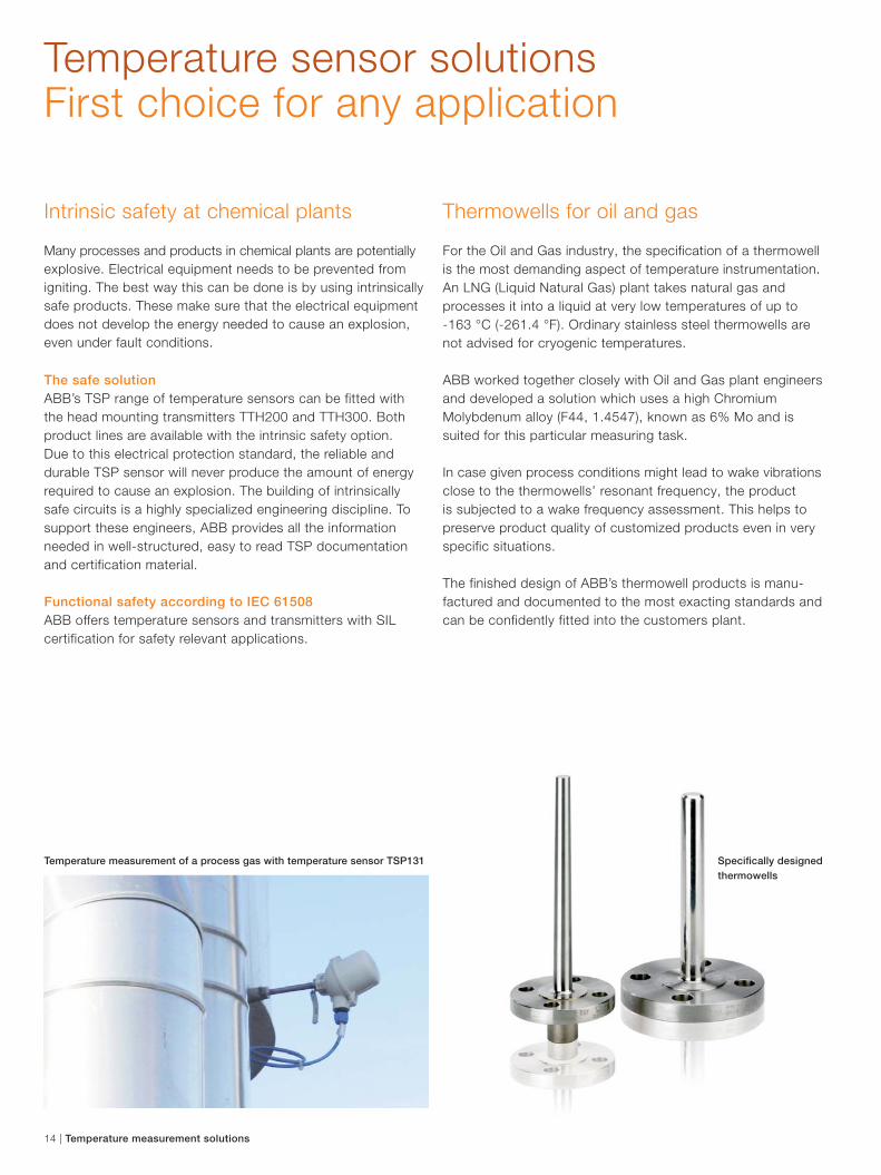
Temperature measurement of a process gas with temperature sensor TSP131
Temperature sensor solutions First choice for any application
Intrinsic safety at chemical plants
Many processes and products in chemical plants are potentially
explosive. Electrical equipment needs to be prevented from
igniting. The best way this can be done is by using intrinsically
safe products. These make sure that the electrical equipment
does not develop the energy needed to cause an explosion,
even under fault conditions.
The safe solution
ABB’s TSP range of temperature sensors can be fitted with
the head mounting transmitters TTH200 and TTH300. Both
product lines are available with the intrinsic safety option.
Due to this electrical protection standard, the reliable and
durable TSP sensor will never produce the amount of energy
required to cause an explosion. The building of intrinsically
safe circuits is a highly specialized engineering discipline. To
support these engineers, ABB provides all the information
needed in well-structured, easy to read TSP documentation
and certification material.
Functional safety according to IEC 61508
ABB offers temperature sensors and transmitters with SIL
certification for safety relevant applications.
Thermowells for oil and gas
For the Oil and Gas industry, the specification of a thermowell
is the most demanding aspect of temperature instrumentation.
An LNG (Liquid Natural Gas) plant takes natural gas and
processes it into a liquid at very low temperatures of up to
-163 °C (-261.4 °F). Ordinary stainless steel thermowells are
not advised for cryogenic temperatures.
ABB worked together closely with Oil and Gas plant engineers
and developed a solution which uses a high Chromium
Molybdenum alloy (F44, 1.4547), known as 6% Mo and is
suited for this particular measuring task.
In case given process conditions might lead to wake vibrations
close to the thermowells’ resonant frequency, the product
is subjected to a wake frequency assessment. This helps to
preserve product quality of customized products even in very
specific situations.
The finished design of ABB’s thermowell products is manu-
factured and documented to the most exacting standards and
can be confidently fitted into the customers plant.
Specifi cally designed
thermowells
14 | Temperature measurement solutions
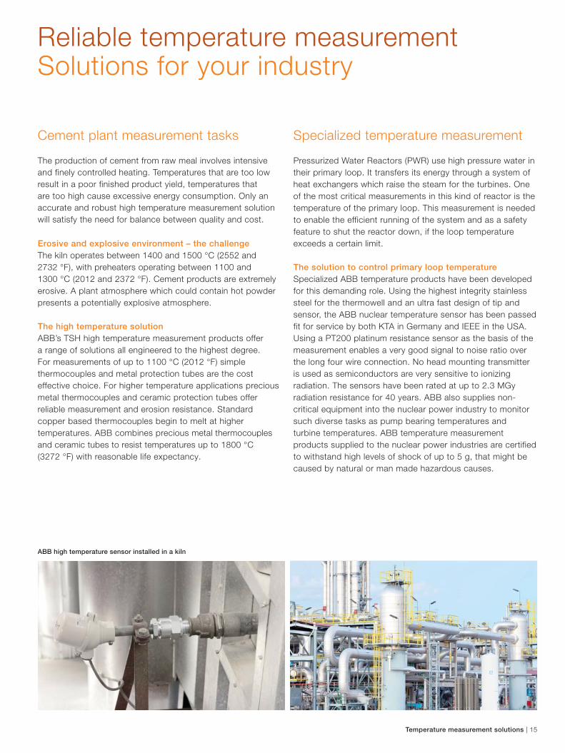
Cement plant measurement tasks
The production of cement from raw meal involves intensive
and finely controlled heating. Temperatures that are too low
result in a poor finished product yield, temperatures that
are too high cause excessive energy consumption. Only an
accurate and robust high temperature measurement solution
will satisfy the need for balance between quality and cost.
Erosive and explosive environment – the challenge
The kiln operates between 1400 and 1500 °C (2552 and
2732 °F), with preheaters operating between 1100 and
1300 °C (2012 and 2372 °F). Cement products are extremely
erosive. A plant atmosphere which could contain hot powder
presents a potentially explosive atmosphere.
The high temperature solution
ABB’s TSH high temperature measurement products offer
a range of solutions all engineered to the highest degree.
For measurements of up to 1100 °C (2012 °F) simple
thermocouples and metal protection tubes are the cost
effective choice. For higher temperature applications precious
metal thermocouples and ceramic protection tubes offer
reliable measurement and erosion resistance. Standard
copper based thermocouples begin to melt at higher
temperatures. ABB combines precious metal thermocouples
and ceramic tubes to resist temperatures up to 1800 °C
(3272 °F) with reasonable life expectancy.
ABB high temperature sensor installed in a kiln
Reliable temperature measurement Solutions for your industry
Specialized temperature measurement
Pressurized Water Reactors (PWR) use high pressure water in
their primary loop. It transfers its energy through a system of
heat exchangers which raise the steam for the turbines. One
of the most critical measurements in this kind of reactor is the
temperature of the primary loop. This measurement is needed
to enable the efficient running of the system and as a safety
feature to shut the reactor down, if the loop temperature
exceeds a certain limit.
The solution to control primary loop temperature
Specialized ABB temperature products have been developed
for this demanding role. Using the highest integrity stainless
steel for the thermowell and an ultra fast design of tip and
sensor, the ABB nuclear temperature sensor has been passed
fit for service by both KTA in Germany and IEEE in the USA.
Using a PT200 platinum resistance sensor as the basis of the
measurement enables a very good signal to noise ratio over
the long four wire connection. No head mounting transmitter
is used as semiconductors are very sensitive to ionizing
radiation. The sensors have been rated at up to 2.3 MGy
radiation resistance for 40 years. ABB also supplies non-
critical equipment into the nuclear power industry to monitor
such diverse tasks as pump bearing temperatures and
turbine temperatures. ABB temperature measurement
products supplied to the nuclear power industries are certified
to withstand high levels of shock of up to 5 g, that might be
caused by natural or man made hazardous causes.
Temperature measurement solutions | 15

Product series TTH200 TTR200
Communication protocol HART
Device type Head mounted temperature transmitter Rail mounted temperature transmitter
Input – One sensor
- Resistance thermometers, resistance-type transmitters (0…5000 Ohm)
- Thermocouples, voltages, mV transmitter (-125…1100 mV)
Sensor connection Pt100 2-, 3-, 4 wire, thermocouple with internal cold junction
Technical features – Continuous sensor monitoring and self-monitoring
- Supply voltage monitoring
- Wire break and corrosion monitoring
– Sensor error adjustment
– Electrical isolation
Display (optional) Transmitter-controlled graphic (alphanumeric)
LCD display type AS for process-, sensor- or
current-value display
Confi guration DTM, EDD
Functional safety SIL2, SIL3 in Dual Confi guration in accordance with IEC 61508
Approvals for explosion protection IECEx, ATEX, FM, CSA, GOST, other approvals are pending
Data sheet for detailed information DS/TTH200 DS/TTR200
Temperature transmitter series 200For demanding applications
16 | Temperature measurement solutions
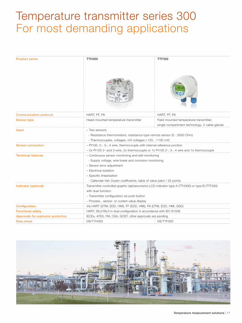
Temperature transmitter series 300For most demanding applications
Product series TTH300 TTF300
Communication protocol HART, FF, PA HART, FF, PA
Device type Head-mounted temperature transmitter Field-mounted temperature transmitter,
single compartment technology, 2 cable glands
Input – Two sensors
- Resistance thermometers, resistance-type remote sensor (0…5000 Ohm)
- Thermocouples, voltages, mV voltages (-125…1100 mV)
Sensor connection – Pt100, 2-, 3-, 4 wire, thermocouple with internal reference junction
– 2x Pt100 2- and 3-wire, 2x thermocouple or 1x Pt100 2-, 3-, 4 wire and 1x thermocouple
Technical features – Continuous sensor monitoring and self-monitoring
- Supply voltage, wire break and corrosion monitoring
– Sensor error adjustment
– Electrical isolation
– Specific linearization
- Callendar-Van Dusen coefficients, table of value pairs / 32 points
Indicator (optional) Transmitter-controlled graphic (alphanumeric) LCD indicator type A (TTH300) or type B (TTF300)
with dual function:
– Transmitter confi guration via push button
– Process-, sensor- or current-value display
Confi guration Via HART (DTM, EDD, HMI), FF (EDD, HMI), PA (DTM, EDD, HMI, GSD)
Functional safety HART, SIL2/SIL3 in dual confi guration in accordance with IEC 61508
Approvals for explosion protection IECEx, ATEX, FM, CSA, GOST, other approvals are pending
Data sheet DS/TTH300 DS/TTF300
Temperature measurement solutions | 17
Temperature transmitter solutions First choice for any application
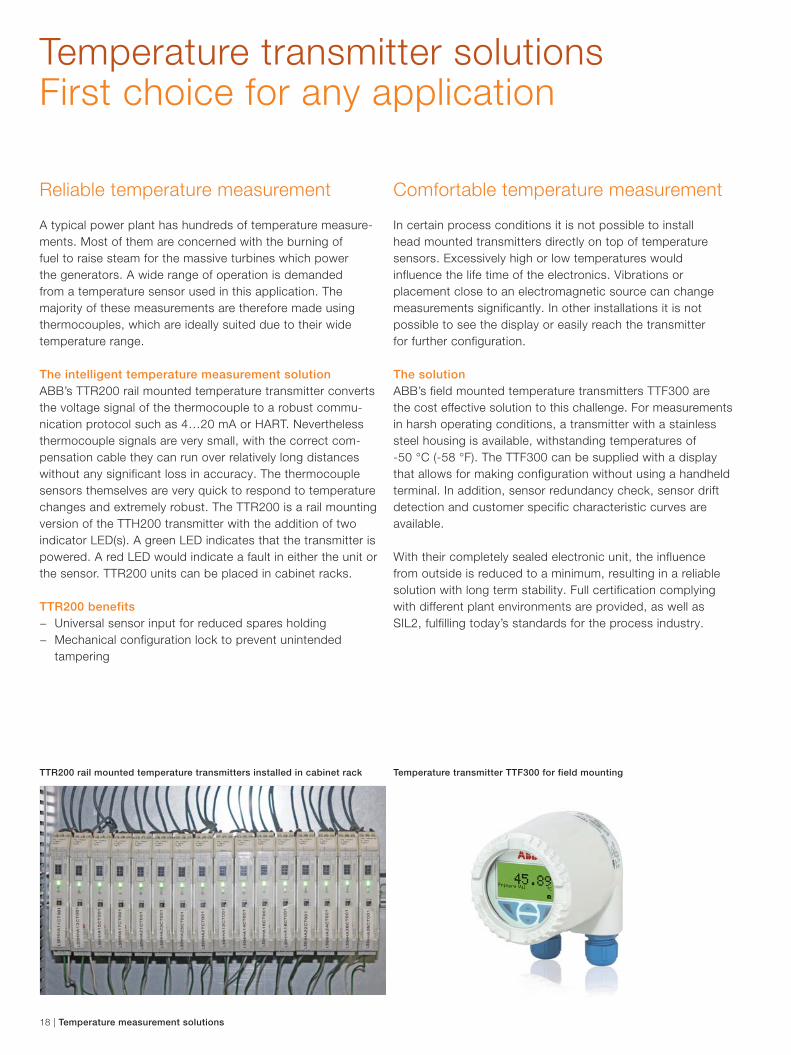
Reliable temperature measurement
A typical power plant has hundreds of temperature measure-
ments. Most of them are concerned with the burning of
fuel to raise steam for the massive turbines which power
the generators. A wide range of operation is demanded
from a temperature sensor used in this application. The
majority of these measurements are therefore made using
thermocouples, which are ideally suited due to their wide
temperature range.
The intelligent temperature measurement solution
ABB’s TTR200 rail mounted temperature transmitter converts
the voltage signal of the thermocouple to a robust commu-
nication protocol such as 4…20 mA or HART. Nevertheless
thermocouple signals are very small, with the correct com-
pensation cable they can run over relatively long distances
without any significant loss in accuracy. The thermocouple
sensors themselves are very quick to respond to temperature
changes and extremely robust. The TTR200 is a rail mounting
version of the TTH200 transmitter with the addition of two
indicator LED(s). A green LED indicates that the transmitter is
powered. A red LED would indicate a fault in either the unit or
the sensor. TTR200 units can be placed in cabinet racks.
TTR200 benefits
− Universal sensor input for reduced spares holding
− Mechanical configuration lock to prevent unintended
tampering
Comfortable temperature measurement
In certain process conditions it is not possible to install
head mounted transmitters directly on top of temperature
sensors. Excessively high or low temperatures would
influence the life time of the electronics. Vibrations or
placement close to an electromagnetic source can change
measurements significantly. In other installations it is not
possible to see the display or easily reach the transmitter
for further configuration.
The solution
ABB’s field mounted temperature transmitters TTF300 are
the cost effective solution to this challenge. For measurements
in harsh operating conditions, a transmitter with a stainless
steel housing is available, withstanding temperatures of
-50 °C (-58 °F). The TTF300 can be supplied with a display
that allows for making configuration without using a handheld
terminal. In addition, sensor redundancy check, sensor drift
detection and customer specific characteristic curves are
available.
With their completely sealed electronic unit, the influence
from outside is reduced to a minimum, resulting in a reliable
solution with long term stability. Full certification complying
with different plant environments are provided, as well as
SIL2, fulfilling today’s standards for the process industry.
TTR200 rail mounted temperature transmitters installed in cabinet rack Temperature transmitter TTF300 for field mounting
18 | Temperature measurement solutions
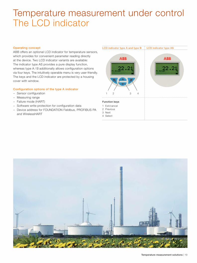
LCD indicator type A and type B LCD indicator type AS
Temperature measurement under control The LCD indicator
Operating concept
ABB offers an optional LCD indicator for temperature sensors,
which provides for convenient parameter reading directly
at the device. Two LCD indicator variants are available:
The indicator type AS provides a pure display function,
whereas type A / B additionally allows configuration options
via four keys. The intuitively operable menu is very user-friendly.
The keys and the LCD indicator are protected by a housing
cover with window.
Configuration options of the type A indicator
− Sensor configuration
− Measuring range
− Failure mode (HART)
− Software write protection for configuration data
− Device address for FOUNDATION Fieldbus, PROFIBUS PA
and WirelessHART
Function keys
1 Exit/cancel
2 Previous
3 Next
4 Select
1 2 3 4
Temperature measurement solutions | 19

Note:
Copyright© 2015 ABB
All rights reserved
® WirelessHART is a registered trademark of
the FieldComm Group, Austin, Texas, USA
To find your local ABB contact visit:
www.abb.com/contacts
For more product information visit:
www.abb.com/temperature
Contact us
PB
/TE
MP
ER
AT
UR
E-E
N R
ev.
A 0
3.2
01
5

Data Sheet DS/TSP1X1-EN Rev. B
SensyTemp TSP111, TSP121, TSP131 Temperature Sensors
Modular design equals flexibility
DIN 43772 Design Modular design — Measuring inset, thermowell, extension tube, connection
head, transmitter Interchangeable measuring inset — Interchangeable measuring inset Transmitter in connection head — Optional LCD indicator — Optional display function (type AS) or display with
configuration function (type A) — SIL2 for transmitter
Approvals — SIL2 for temperature sensor — ATEX — GOST Applications — Chemical industry — Energy industry — General process engineering — Tank and pipeline construction — Mechanical and plant engineering
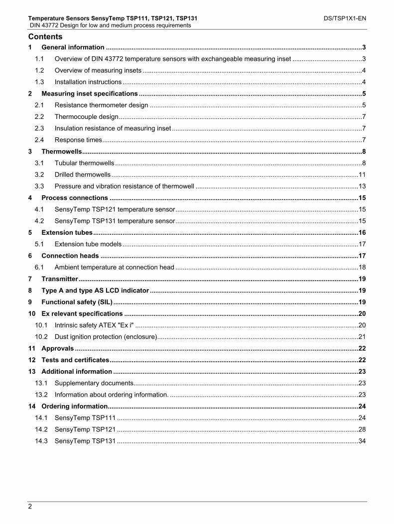
Contents
Temperature Sensors SensyTemp TSP111, TSP121, TSP131 DS/TSP1X1-EN DIN 43772 Design for low and medium process requirements
2
Contents 1 General information ............................................................................................................................................3
1.1 Overview of DIN 43772 temperature sensors with exchangeable measuring inset ......................................3 1.2 Overview of measuring insets ........................................................................................................................4 1.3 Installation instructions ...................................................................................................................................4
2 Measuring inset specifications ..........................................................................................................................5 2.1 Resistance thermometer design ....................................................................................................................5 2.2 Thermocouple design.....................................................................................................................................7 2.3 Insulation resistance of measuring inset ........................................................................................................7 2.4 Response times..............................................................................................................................................7
3 Thermowells.........................................................................................................................................................8 3.1 Tubular thermowells .......................................................................................................................................8 3.2 Drilled thermowells .......................................................................................................................................11 3.3 Pressure and vibration resistance of thermowell .........................................................................................13
4 Process connections ........................................................................................................................................15 4.1 SensyTemp TSP121 temperature sensor....................................................................................................15 4.2 SensyTemp TSP131 temperature sensor....................................................................................................15
5 Extension tubes.................................................................................................................................................16 5.1 Extension tube models .................................................................................................................................17
6 Connection heads .............................................................................................................................................17 6.1 Ambient temperature at connection head ....................................................................................................18
7 Transmitter.........................................................................................................................................................19 8 Type A and type AS LCD indicator ..................................................................................................................19 9 Functional safety (SIL) ......................................................................................................................................19 10 Ex relevant specifications ................................................................................................................................20
10.1 Intrinsic safety ATEX "Ex i" ..........................................................................................................................20 10.2 Dust ignition protection (enclosure)..............................................................................................................21
11 Approvals ...........................................................................................................................................................22 12 Tests and certificates........................................................................................................................................22 13 Additional information ......................................................................................................................................23
13.1 Supplementary documents...........................................................................................................................23 13.2 Information about ordering information. .......................................................................................................23
14 Ordering information.........................................................................................................................................24 14.1 SensyTemp TSP111 ....................................................................................................................................24 14.2 SensyTemp TSP121 ....................................................................................................................................28 14.3 SensyTemp TSP131 ....................................................................................................................................34
Data Sheet Temperature Sensors
SensyTemp TSP111, TSP121, TSP131

Temperature Sensors SensyTemp TSP111, TSP121, TSP131 DS/TSP1X1-EN DIN 43772 Design for low and medium process requirements
3
A
1 General information
1.1 Overview of DIN 43772 temperature sensors with exchangeable measuring inset
Type TSP111 TSP121 TSP131
Legend K = Ext. tube length U = Installation length N = Nominal length L = Thermowell length
K
U
N
U
K
K
L
No thermowell, for installation in existing thermowell
Welded protective fitting manufactured from pipe material
Drilled thermowell manufactured from bar stock material
Design
Measuring inset, extension tube with thermowell interface, connection head, transmitter, optional LCD indicator
Process connection Insertion in an existing thermowell. Functional safety is only assured with an additional thermowell!
Screw-in thread, flange, compression fitting
Welded connections, screw-in thread, flange
Transport temperature / Storage temperature
-20 ... 70 °C (-4 ... 158 °F)
Maximum temperature limits (depending on the sensor and material selected, the lower temperature value in each case counts) Thin film measurement resistor: 500 °C (932 °F)
Wire-wound measurement resistor: 600 °C (1,112 °F) Sensor
Type K, N, J, and E thermocouples: 1,250 °C (2,282 °F) 316L / 1.4404 ≤ 600 °C (1,112 °F) 316Ti / 1.4571 ≤ 800 °C (1,472 °F) Hastelloy C276 / 2.4819 ≤ 1,100 °C (2,012 °F)
Inconel 600 / 2.4816 - ≤ 1,100 °C (2,012 °F) ≤ 1,100 °C (2,012 °F)
Monel 400 / 2.4360 - - 550 °C (1,022°F)
1.7335 - - ≤ 540 °C (1,004 °F) 1.7380 - - ≤ 570 °C (1,058 °F) 1.5415 - - ≤ 500 °C (932 °F) E-CTFE - ≤ 120 °C (248 °F) ≤ 120 °C (248 °F)
Material
Tantalum - ≤ 200 °C (392 °F) ≤ 200 °C (392 °F)
Pressure - Maximum 40 ... 100 bar (580.15 ... 1,450.38 psi) Maximum 700 bar (10,152.64 psi)
Important The maximum temperatures and pressures specified are maximum values and do not take into consideration process-related stress. The effects of viscosity, flow rate, pressure, and temperature in the process usually cause these values to drop.

Temperature Sensors SensyTemp TSP111, TSP121, TSP131 DS/TSP1X1-EN DIN 43772 Design for low and medium process requirements
4
1.2 Overview of measuring insets
Type TSA101 Legend M = Measuring inset length U = Installation length K = Ext. tube length N = Nominal length L = Thermowell length D = Outer diameter TSP111 M = U + K + 40 mm TSP121 M = N + 40 mm TSP131 M = L + K + 40 mm
M
A00054
M
M
Ceramic base with connection
terminals Permanently-mounted transmitter Open leads Design
• Bendable and vibration-resistant ABB plastic-sheathed cable. The sheath for the resistance thermometer is manufactured from stainless steel 1.4571 (316Ti) or highly heat-resistant steel 2.4816 (alloy 600) for thermocouples.
• Sensors conforming to IEC 60751 platinum resistance thermometer with measuring ranges of -196 ... 600 °C (-384.8 ... 1,112 °F) in three tolerance classes or thermocouples conforming to IEC 60584 and ANSI MC96.1 with measuring ranges of -40 ... 1,100 °C (-40 ... 2,012 °F), each in two tolerance classes.
• Fitted with single or double sensors. • Optimum clamping at the measuring inset's holding plate is assured by generous spring travel
(10 mm (0.39 inch)) on the part of the clamping springs. • Measuring insets are available with outer diameters of 3.0 mm (0.12 inch), 6.0 mm (0.24 inch),
8.0 mm (0.318 inch), and 10.0 mm (0.39 inch).
Change from one to two columns
1.3 Installation instructions
Ideally, in the case of pipes, the tip of the thermometer should be located in the center of the pipe. If this is not possible, both in the case of pipes and with containers, a minimum insertion depth of 10 to 15 times the thermowell diameter is assumed to be sufficient.
Fig. 1
1.3.1
Insufficient nominal diameter
Pipes with very small nominal diameters, insertion inside an elbow pipe is recommended. The tip of the thermowell should be set in the opposite direction of the flow.. Inserting the thermowell with an adapter at an acute angle against the flow direction can also distort measurement results.
Fig. 2
Change from one to two columns
Temperature Sensors SensyTemp TSP111, TSP121, TSP131 DS/TSP1X1-EN DIN 43772 Design for low and medium process requirements
5
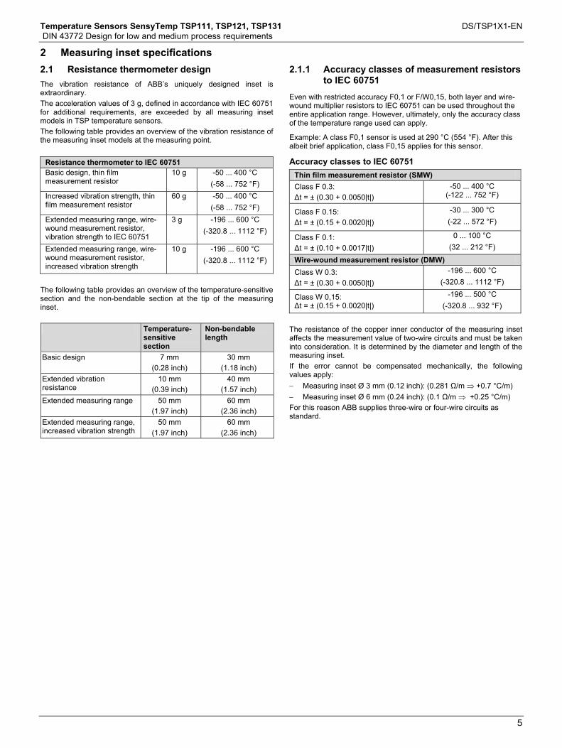
2 Measuring inset specifications Change from one to two columns
2.1 Resistance thermometer design
The vibration resistance of ABB’s uniquely designed inset is extraordinary. The acceleration values of 3 g, defined in accordance with IEC 60751 for additional requirements, are exceeded by all measuring inset models in TSP temperature sensors. The following table provides an overview of the vibration resistance of the measuring inset models at the measuring point.
Resistance thermometer to IEC 60751 Basic design, thin film measurement resistor
10 g -50 ... 400 °C (-58 ... 752 °F)
Increased vibration strength, thin film measurement resistor
60 g -50 ... 400 °C (-58 ... 752 °F)
Extended measuring range, wire-wound measurement resistor, vibration strength to IEC 60751
3 g -196 ... 600 °C (-320.8 ... 1112 °F)
Extended measuring range, wire-wound measurement resistor, increased vibration strength
10 g -196 ... 600 °C (-320.8 ... 1112 °F)
The following table provides an overview of the temperature-sensitive section and the non-bendable section at the tip of the measuring inset. Temperature-
sensitive section
Non-bendable length
Basic design 7 mm (0.28 inch)
30 mm (1.18 inch)
Extended vibration resistance
10 mm (0.39 inch)
40 mm (1.57 inch)
Extended measuring range 50 mm (1.97 inch)
60 mm (2.36 inch)
Extended measuring range, increased vibration strength
50 mm (1.97 inch)
60 mm (2.36 inch)
2.1.1 Accuracy classes of measurement resistors to IEC 60751
Even with restricted accuracy F0,1 or F/W0,15, both layer and wire-wound multiplier resistors to IEC 60751 can be used throughout the entire application range. However, ultimately, only the accuracy class of the temperature range used can apply.
Example: A class F0,1 sensor is used at 290 °C (554 °F). After this albeit brief application, class F0,15 applies for this sensor.
Accuracy classes to IEC 60751 Thin film measurement resistor (SMW) Class F 0.3: Δt = ± (0.30 + 0.0050|t|)
-50 ... 400 °C (-122 ... 752 °F)
Class F 0.15: Δt = ± (0.15 + 0.0020|t|)
-30 ... 300 °C (-22 ... 572 °F)
Class F 0.1: Δt = ± (0.10 + 0.0017|t|)
0 ... 100 °C (32 ... 212 °F)
Wire-wound measurement resistor (DMW) Class W 0.3: Δt = ± (0.30 + 0.0050|t|)
-196 ... 600 °C (-320.8 ... 1112 °F)
Class W 0,15: Δt = ± (0.15 + 0.0020|t|)
-196 ... 500 °C (-320.8 ... 932 °F)
The resistance of the copper inner conductor of the measuring inset affects the measurement value of two-wire circuits and must be taken into consideration. It is determined by the diameter and length of the measuring inset. If the error cannot be compensated mechanically, the following values apply: − Measuring inset Ø 3 mm (0.12 inch): (0.281 Ω/m ⇒ +0.7 °C/m) − Measuring inset Ø 6 mm (0.24 inch): (0.1 Ω/m ⇒ +0.25 °C/m) For this reason ABB supplies three-wire or four-wire circuits as standard.

Temperature Sensors SensyTemp TSP111, TSP121, TSP131 DS/TSP1X1-EN DIN 43772 Design for low and medium process requirements
6
2.1.2 Versions
Basic Version Thin film measurement resistor (SMW) Measuring range -50 … 400 °C (-122 … 752 °F) Vibration-resistant up to 10 g
Single sensor Double sensor 2-w. 3-w. 4-w. 2-w. 3-w. 4-w. 3 mm, class B 3 mm, class A 6 mm, class B
6 mm, class A
6 mm, class AA Increased vibration resistance
Thin film measurement resistor (SMW) Measuring range -50 … 400 °C (-122 … 752 °F) Vibration-resistant up to 60 g
Single sensor Double sensor 2-w. 3-w. 4-w. 2-w. 3-w. 4-w. 3 mm, class B 3 mm, class A 6 mm, class B
6 mm, class A Extended measuring range
Wire-wound measurement resistor (DMW) Measuring range -196 … 600 °C (-320.8 … 1,112 °F) Vibration-resistant up to 3 g
Single sensor Double sensor 2-w. 3-w. 4-w. 2-w. 3-w. 4-w.
3 mm, class B 3 mm, class A 6 mm, class B
6 mm, class A Extended measuring range, increased vibration strength
Wire-wound measurement resistor (DMW) Measuring range -196 … 600 °C (-320.8 … 1,112 °F) Vibration-resistant up to 10 g
Single sensor Double sensor 2-w. 3-w. 4-w. 2-w. 3-w. 4-w. 3 mm, class B 3 mm, class A 6 mm, class B
6 mm, class A
Temperature Sensors SensyTemp TSP111, TSP121, TSP131 DS/TSP1X1-EN DIN 43772 Design for low and medium process requirements
7
2.2 Thermocouple design
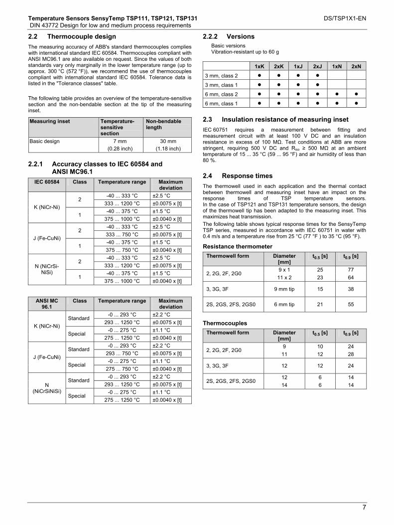
The measuring accuracy of ABB's standard thermocouples complies with international standard IEC 60584. Thermocouples compliant with ANSI MC96.1 are also available on request. Since the values of both standards vary only marginally in the lower temperature range (up to approx. 300 °C (572 °F)), we recommend the use of thermocouples compliant with international standard IEC 60584. Tolerance data is listed in the "Tolerance classes" table. The following table provides an overview of the temperature-sensitive section and the non-bendable section at the tip of the measuring inset.
Measuring inset Temperature-sensitive section
Non-bendable length
Basic design 7 mm (0.28 inch)
30 mm (1.18 inch)
2.2.1 Accuracy classes to IEC 60584 and
ANSI MC96.1
IEC 60584 Class Temperature range Maximum deviation
-40 ... 333 °C ±2.5 °C 2
333 ... 1200 °C ±0.0075 x [t] -40 ... 375 °C ±1.5 °C
K (NiCr-Ni) 1
375 ... 1000 °C ±0.0040 x [t] -40 ... 333 °C ±2.5 °C
2 333 ... 750 °C ±0.0075 x [t] -40 ... 375 °C ±1.5 °C
J (Fe-CuNi) 1
375 ... 750 °C ±0.0040 x [t] -40 ... 333 °C ±2.5 °C
2 333 ... 1200 °C ±0.0075 x [t] -40 ... 375 °C ±1.5 °C
N (NiCrSi-NiSi)
1 375 ... 1000 °C ±0.0040 x [t]
ANSI MC
96.1 Class Temperature range Maximum
deviation -0 ... 293 °C ±2.2 °C
Standard 293 ... 1250 °C ±0.0075 x [t]
-0 ... 275 °C ±1.1 °C K (NiCr-Ni)
Special 275 ... 1250 °C ±0.0040 x [t]
-0 ... 293 °C ±2.2 °C Standard
293 ... 750 °C ±0.0075 x [t] -0 ... 275 °C ±1.1 °C
J (Fe-CuNi) Special
275 ... 750 °C ±0.0040 x [t] -0 ... 293 °C ±2.2 °C
Standard 293 ... 1250 °C ±0.0075 x [t]
-0 ... 275 °C ±1.1 °C N
(NiCrSiNiSi) Special
275 ... 1250 °C ±0.0040 x [t]
2.2.2 Versions
Basic versions Vibration-resistant up to 60 g
1xK 2xK 1xJ 2xJ 1xN 2xN
3 mm, class 2
3 mm, class 1
6 mm, class 2
6 mm, class 1
2.3 Insulation resistance of measuring inset
IEC 60751 requires a measurement between fitting and measurement circuit with at least 100 V DC and an insulation resistance in excess of 100 MΩ. Test conditions at ABB are more stringent, requiring 500 V DC and Riso ≥ 500 MΩ at an ambient temperature of 15 ... 35 °C (59 ... 95 °F) and air humidity of less than 80 %.
2.4 Response times
The thermowell used in each application and the thermal contact between thermowell and measuring inset have an impact on the response times of TSP temperature sensors. In the case of TSP121 and TSP131 temperature sensors, the design of the thermowell tip has been adapted to the measuring inset. This maximizes heat transmission. The following table shows typical response times for the SensyTemp TSP series, measured in accordance with IEC 60751 in water with 0.4 m/s and a temperature rise from 25 °C (77 °F ) to 35 °C (95 °F).
Resistance thermometer Thermowell form Diameter
[mm] t0.5 [s] t0.9 [s]
9 x 1 25 77 2, 2G, 2F, 2G0
11 x 2 23 64
3, 3G, 3F 9 mm tip 15 38
2S, 2GS, 2FS, 2GS0 6 mm tip 21 55
Thermocouples
Thermowell form Diameter [mm]
t0.5 [s] t0.9 [s]
9 10 24 2, 2G, 2F, 2G0
11 12 28
3, 3G, 3F 12 12 24
12 6 14 2S, 2GS, 2FS, 2GS0
14 6 14

Temperature Sensors SensyTemp TSP111, TSP121, TSP131 DS/TSP1X1-EN DIN 43772 Design for low and medium process requirements
8
3 Thermowells Change from one to two columns
Thermowell functions • Protection against aggressive media, high process pressures,
and high flow rates • Replacement or recalibration of the measuring unit without
interrupting the process Depending on the medium, temperature, and process pressure, several different designs and materials are available. The thermowells are divided into 2 categories:
• Welded protective fittings manufactured from pipe material for TSP121
• Drilled thermowells manufactured from bar stock material for TSP131
Available in accordance with DIN 43772 or ABB standard.
Use in highly aggressive media • A special coating can be applied to stainless steel flange
thermowells, e.g., 0.5 mm (0.02 inch) E-CTFE. Use in highly corrosive applications
• Thermowells can also be given a tantalum sheath consisting of a single-sided, closed tube with a 13 mm (0.51 inch) diameter and flange disc. Requirements:
• TSP121 with flange thermowell (form 2F or 3F) • Diameter 12 mm (0.47 inch) • Material 1.4571 or 1.4404
Standard lengths for welded thermowells N = 230 mm (9.06 inch) U = 100 mm (3.94 inch) N = 290 mm (11.42 inch) U = 160 mm (6.3 inch) N = 380 mm (14.96 inch) U = 250 mm (9.84 inch) N = 530 mm (20.87 inch) U = 400 mm (15.75 inch)
Change from one to two columns
3.1 Tubular thermowells
Thermowell type DIN 43772 – Form 2 DIN 43772 – Form 2G DIN 43772 – Form 2F Thermowell form
Design Straight shaft Straight shaft Straight shaft Material Diameter 1.4571
1.4404 12, 1412, 14
1.4571 1.4404 2.4819 1)
9, 11, 12, 1412, 14
13,7
1.4571 1.4404 2.4819 2)
11, 12, 1412, 14
13,7
Measuring inset diameter SR-∅ 12: 6 SR-∅ 12: 6
SR-∅ 9, 11, 12, 13,7: 6 SR-∅ 14: 6
SR-∅ 11, 12, 13,7: 6 SR-∅ 14: 6
Temperature Sensors SensyTemp TSP111, TSP121, TSP131 DS/TSP1X1-EN DIN 43772 Design for low and medium process requirements
9
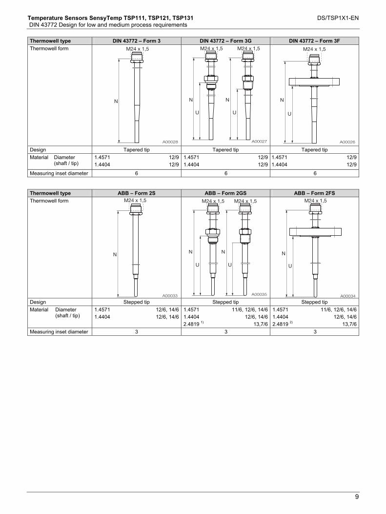
Thermowell type DIN 43772 – Form 3 DIN 43772 – Form 3G DIN 43772 – Form 3F Thermowell form
Design Tapered tip Tapered tip Tapered tip Material Diameter
(shaft / tip) 1.4571 1.4404
12/912/9
1.4571 1.4404
12/912/9
1.4571 1.4404
12/912/9
Measuring inset diameter 6 6 6 Thermowell type ABB – Form 2S ABB – Form 2GS ABB – Form 2FS Thermowell form
Design Stepped tip Stepped tip Stepped tip Material Diameter
(shaft / tip) 1.4571 1.4404
12/6, 14/612/6, 14/6
1.4571 1.4404 2.4819 1)
11/6, 12/6, 14/612/6, 14/6
13,7/6
1.4571 1.4404 2.4819 2)
11/6, 12/6, 14/612/6, 14/6
13,7/6Measuring inset diameter 3 3 3

Temperature Sensors SensyTemp TSP111, TSP121, TSP131 DS/TSP1X1-EN DIN 43772 Design for low and medium process requirements
10
Thermowell type ABB – 2G0 ABB – 2GS0 Thermowell form
Design No extension tube, straight shaft No extension tube, stepped tip Material Diameter
(shaft / tip) 1.4571 1) 9, 11 1.4571 1) 11/6
Measuring inset diameter 6 3 Dimensions in mm 1) Only with G1/2A, 1/2“ NPT thread 2) 1.4571 flange, 2.4819 flange disc
Temperature Sensors SensyTemp TSP111, TSP121, TSP131 DS/TSP1X1-EN DIN 43772 Design for low and medium process requirements
11
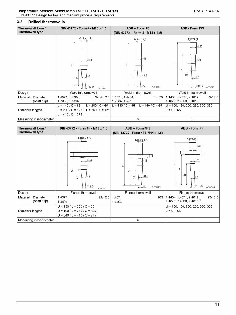
3.2 Drilled thermowells
Thermowell form / Thermowell type
DIN 43772 - Form 4 - M18 x 1.5 ABB – Form 4S (DIN 43772 – Form 4 - M14 x 1.5)
ABB - Form PW
Design Weld-in thermowell Weld-in thermowell Weld-in thermowell Material Diameter
(shaft / tip) 1.4571, 1.4404, 1.7335, 1.5415
24h7/12,5 1.4571, 1.4404, 1.7335, 1.5415
18h7/9 1.4404, 1.4571, 2.4819, 1.4876, 2.4360, 2.4816
32/13,5
Standard lengths L = 140 / C = 65 L = 200 / C = 125 L = 410 / C = 275
L = 200 / C= 65 L = 260 / C= 125
L = 110 / C = 65 L = 140 / C = 65 U = 100, 150, 200, 250, 300, 350 L = U + 65
Measuring inset diameter 6 3 6
Thermowell form / Thermowell type
DIN 43772 - Form 4F - M18 x 1.5 ABB – Form 4FS (DIN 43772 - Form 4FS M14 x 1.5)
ABB - Form PF
Design Flange thermowell Flange thermowell Flange thermowell Material Diameter
(shaft / tip) 1.4571 1.4404
24/12,5 1.4571 1.4404
18/9 1.4404, 1.4571, 2.4819, 1.4876, 2.4360, 2.4816 1)
23/13,5
Standard lengths U = 130 / L = 200 / C = 65 U = 190 / L = 260 / C = 125 U = 340 / L = 410 / C = 275
U = 100, 150, 200, 250, 300, 350 L = U + 65
Measuring inset diameter 6 3 6
Temperature Sensors SensyTemp TSP111, TSP121, TSP131 DS/TSP1X1-EN DIN 43772 Design for low and medium process requirements
12
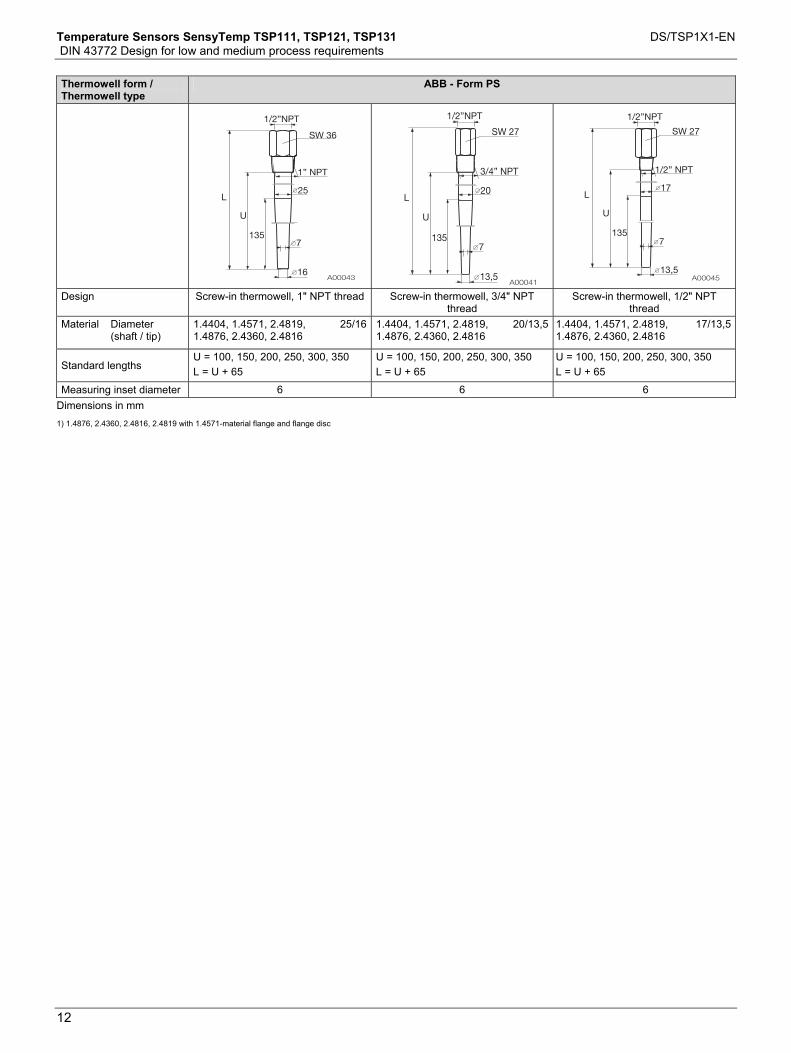
Thermowell form / Thermowell type
ABB - Form PS
Design Screw-in thermowell, 1" NPT thread Screw-in thermowell, 3/4" NPT thread
Screw-in thermowell, 1/2" NPT thread
Material Diameter (shaft / tip)
1.4404, 1.4571, 2.4819, 1.4876, 2.4360, 2.4816
25/16 1.4404, 1.4571, 2.4819, 1.4876, 2.4360, 2.4816
20/13,5 1.4404, 1.4571, 2.4819,1.4876, 2.4360, 2.4816
17/13,5
Standard lengths U = 100, 150, 200, 250, 300, 350 L = U + 65
U = 100, 150, 200, 250, 300, 350 L = U + 65
U = 100, 150, 200, 250, 300, 350 L = U + 65
Measuring inset diameter 6 6 6 Dimensions in mm 1) 1.4876, 2.4360, 2.4816, 2.4819 with 1.4571-material flange and flange disc

Temperature Sensors SensyTemp TSP111, TSP121, TSP131 DS/TSP1X1-EN DIN 43772 Design for low and medium process requirements
13
Change from one to two columns
3.3 Pressure and vibration resistance of thermowell
The permissible compressive loads for thermowells at various temperatures are illustrated in the following figures (thermowells conforming to DIN 43772). The curves can also be applied to identical thermowell models. Thermowell form 2 (material 1.4571)
Fig. 1 X Vapor-pressure curve VL Flow rate in air VW Flow rate in water VD Flow rate in vapor
Curve Insertion depth [mm] Thermowell diameter [mm]
2a 250 11 2b 250 14 2c 400 11 2d 400 14
Thermowell form 3 (material 1.4571)
Fig. 2 X Vapor-pressure curve VL Flow rate in air VW Flow rate in water VD Flow rate in vapor
Curve Insertion depth [mm] Thermowell diameter [mm]
3a 225 12/9 3b 285 12/9
Thermowell form 4 (material 1.4571)
A00009
V = 60 m/sL
V = 5 m/sW
V = 60 m/sD
50 100 150 250 300 350200 400 °C4500
120
360
bar
60
240
320
420
480
540
600
180
X4a
4b
4c
4d
4d
4a
4c
4b
4d4a4b,c
Fig. 3 X Vapor-pressure curve VL Flow rate in air VW Flow rate in water VD Flow rate in vapor
Curve Insertion depth [mm] Thermowell diameter [mm]
4a 65 18 4b 125 24 4c 125 26 4d 125 32

Temperature Sensors SensyTemp TSP111, TSP121, TSP131 DS/TSP1X1-EN DIN 43772 Design for low and medium process requirements
14
Thermowell form 4 (material 1.7335 and 1.7380)
Fig. 4 X Vapor-pressure curve VL Flow rate in air VW Flow rate in water VD Flow rate in vapor
Curve Insertion depth [mm] Thermowell diameter [mm]
4a 65 18 4b 125 24
Important The above diagrams have been taken from DIN 43772 and are based on the Dittrich calculation model. They do not take possible vibration caused by vortex excitation of the flowing medium into account. ABB's standard thermowells are sufficiently robust for most industrial applications provided that design, material, and length are properly selected. Most thermowell failures are caused by flow-related vibration. For this reason, ABB offers a stress analysis for ABB thermowells, based on the respective usage parameters. The stress analysis conforms to ASME PTC 19.3. It is based on recognized theoretical methods and is intended to support thermowell selection. It is not, however, a guarantee against failure of the thermowell. Given the relatively unreliable computational estimation of the natural frequency of a thermowell and taking the numerous influencing factors into account, experimental testing is recommended in critical cases. For more detailed information about thermowell loads and calculation methods, please see DIN 43772.
Change from one to two columns

Temperature Sensors SensyTemp TSP111, TSP121, TSP131 DS/TSP1X1-EN DIN 43772 Design for low and medium process requirements
15
4 Process connections
4.1 SensyTemp TSP121 temperature sensor
4.1.1 Weld-in / Plug-in thermowells
Type Compression fitting
Straight form (DIN 43772 – 2)
Tapered tip (DIN 43772 – 3)
Stepped tip (ABB – 2S)
G 1/2A, 1/2" NPT
Important All ABB compression fittings are manufactured from stainless steel and are supplied without material confirmation with acceptance certificate in accordance with EN 10204.
4.1.2 Screw-in thermowells
Type Screw-in thread
Straight form (DIN 43772 – 2G)
Tapered tip (DIN 43772 – 3G)
Stepped tip (ABB – 2GS)
G 1/2''A, G 3/4''A, G 1''A, 1/2'' NPT, 3/4'' NPT, 1'' NPT,
M20 x 1,5, M27 x 2, 1/2'' BSPT, 3/4'' BSPT, 1'' BSPT
No ext. tube (ABB – 2G0)
No ext. tube, stepped tip (ABB – 2GS0) G1/2A, 1/2" NPT
4.1.3 Flange thermowells
Type B1 flange, EN 1092-1 RF flange, ANSI / ASME B16.5 Tri-Clamp flange BS 4825
Straight form (DIN 43772 – 2F)
Tapered tip (DIN 43772 – 3F)
Stepped tip (ABB – 2FS)
DN25 PN40, DN40 PN40, DN50 PN40
1'' 150 lbs., 1'' 300 lbs., 1,5'' 150 lbs., 1,5'' 300 lbs., 1,5'' 600 lbs.,
2'' 150 lbs., 2'' 300 lbs., 2'' 600 lbs 1.5", 2", 2.5",3", 4"
4.2 SensyTemp TSP131 temperature sensor
4.2.1 Screw-in thermowells
Type Screw-in thread Thermowell manufactured from bar stock material (ABB - PS) 1/2" NPT, 3/4'' NPT, 1'' NPT
4.2.2 Flange thermowells
Type B1 flange, EN 1092-1 RF flange, ANSI / ASME B16.5 Tri-Clamp flange BS 4825
Thermowell manufactured from bar stock material (ABB - PF) Thermowell manufactured from bar stock material (DIN 43772 – 4F, F2 = 24 mm)
2", 2.5", 3", 4"
Thermowell manufactured from bar stock material, fast-acting (DIN 43772 – 4F, F2 = 18 mm, ABB – 4FS)
DN25 PN40, DN40 PN40, DN50 PN40
1'' 150 lbs., 1'' 300 lbs., 1,5'' 150 lbs., 1,5'' 300 lbs., 1,5'' 600 lbs.,
2'' 150 lbs., 2'' 300 lbs., 2'' 600 lbs.
1.5", 2", 2.5",3", 4"

Temperature Sensors SensyTemp TSP111, TSP121, TSP131 DS/TSP1X1-EN DIN 43772 Design for low and medium process requirements
16
5 Extension tubes Change from one to two columns
The extension tube is the component between thermowell and connection head. It is used to bridge existing insulation or serves as a cooling section between the transmitter's temperature-sensitive electronics (in the connection head) and the process. The relation illustrated in Fig. 3 led to the selection of the standard extension tube with a length K = 130 mm (5.12 inch). If the two threads are manufactured in one part (known as a double nipple), a minimum length of K = 25 mm (0.98 inch) is possible.
ΔTHead
A00018
800 °C (1472 °F)
620 °C (1148 °F)
430 °C (806 °F)
250 °C (482 °F)
75
2.95
100
3.94
125
4.92
175
6.98
200
7.87
225
8.86
150
5.91
250
9.84
0 32
10 50
20 68
30 86
mm
inch
40 104
50 122
60 140
°C °F
T
T = Process temperature ΔTHead = Increase of temperature in the connection head
Fig. 3: Diagram illustrating extension tube length
Change from one to two columns

Temperature Sensors SensyTemp TSP111, TSP121, TSP131 DS/TSP1X1-EN DIN 43772 Design for low and medium process requirements
17
5.1 Extension tube models
Cylindrical screw-in thread Conical screw-in thread Lock nut, rotatable M24 x 1.5 M24 x 1.5 M24 x 1.5
G 1/2 / M24 x 1.5 / M18 x 1.5 /
M20 x 1.5 1/2“ NPT G 1/2
1/2“ NPT - 1/2“ NPT, not separable (nipple)
1/2“ NPT - 1/2“ NPT, separable (nipple-union)
1/2“ NPT - 1/2“ NPT, separable, fitting in center
(nipple-union-nipple) 1/2“ NPT 1/2“ NPT 1/2“ NPT
1/2“ NPT 1/2“ NPT 1/2“ NPT
When the “no ext. tube” design is ordered, an ext. tube length of K = 0 mm is assumed. As a result, only U needs to be specified. In this case, the installation length U is the same as the nominal length N.
A
6 Connection heads Change from one to two columns
Functions of the connection head • Housing for a transmitter or a terminal block • Protection of the connection area against adverse environmental
effects All ABB standard heads provide ingress protection of at least IP 66, in combination with an ABB thermowell and the M20 x 1.5 cable gland (supplied).
Important The cable glands used are suitable for permanent cable installation.
As an option, the connection heads are also available with a cable entry with a 1/2“ NPTF thread (without cable gland). In this case, the user must put appropriate measures in place to ensure that the required ingress protection level is maintained.
Change from one to two columns
Temperature Sensors SensyTemp TSP111, TSP121, TSP131 DS/TSP1X1-EN DIN 43772 Design for low and medium process requirements
18
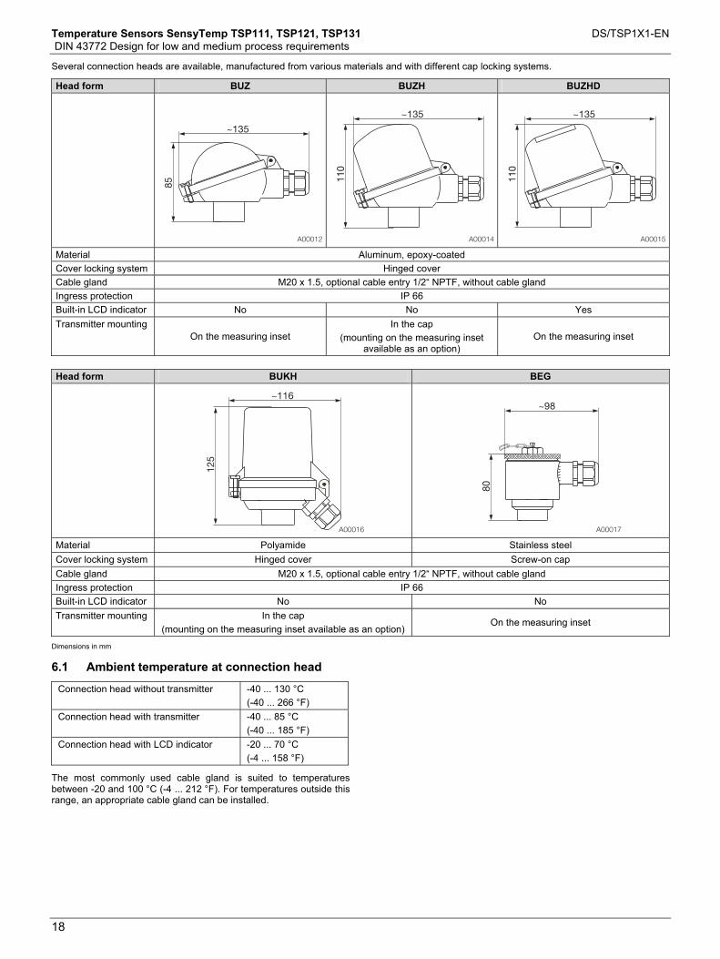
Several connection heads are available, manufactured from various materials and with different cap locking systems.
Head form BUZ BUZH BUZHD
Material Aluminum, epoxy-coated Cover locking system Hinged cover Cable gland M20 x 1.5, optional cable entry 1/2“ NPTF, without cable gland Ingress protection IP 66 Built-in LCD indicator No No Yes Transmitter mounting
On the measuring inset In the cap
(mounting on the measuring inset available as an option)
On the measuring inset
Head form BUKH BEG
Material Polyamide Stainless steel Cover locking system Hinged cover Screw-on cap Cable gland M20 x 1.5, optional cable entry 1/2“ NPTF, without cable gland Ingress protection IP 66 Built-in LCD indicator No No Transmitter mounting In the cap
(mounting on the measuring inset available as an option) On the measuring inset
Dimensions in mm
6.1 Ambient temperature at connection head Change from one to two columns
Connection head without transmitter -40 ... 130 °C (-40 ... 266 °F)
Connection head with transmitter -40 ... 85 °C (-40 ... 185 °F)
Connection head with LCD indicator -20 ... 70 °C (-4 ... 158 °F)
The most commonly used cable gland is suited to temperatures between -20 and 100 °C (-4 ... 212 °F). For temperatures outside this range, an appropriate cable gland can be installed.

Temperature Sensors SensyTemp TSP111, TSP121, TSP131 DS/TSP1X1-EN DIN 43772 Design for low and medium process requirements
19
7 Transmitter
Installing a transmitter has the following advantages:
• Cost reduction due to less wiring expense • Magnification of the sensor signal at the measuring point and
conversion to standard signal format (thereby increasing the signal's interference immunity)
• Option to install an LCD indicator in the connection head • SIL2 with appropriately classified transmitter
The output signal of a temperature sensor is determined by the selection of the corresponding transmitter. When using ABB transmitters, self-heating can be ignored. The following output signals are available:
Type
TR04 4 … 20 mA
TTH200 HART 4 … 20 mA, HART
TTH300 HART 4 … 20 mA, HART
TTH300 PA PROFIBUS PA
TTH300 FF FOUNDATION
Fieldbus H1
8 Type A and type AS LCD indicator
The BUZHD connection head is equipped with a digital LCD indicator. A suitable transmitter is connected via an add-on interface cable. We recommend using an LCD indicator with type AS display function if you are using a TTH200. If the TTH300 transmitter is selected, the type A LCD indicator can also be used for configuring it.
Type A LCD indicator Type AS LCD indicator
A002421 2 3 4 Fig. 4
1 Exit / Cancel 2 Scroll back
3 Scroll forward 4 Select
In the SensyTemp TSP300 temperature sensor series, it is possible to configure the TTH300 using a built-in display.
9 Functional safety (SIL)
SensyTemp TSP temperature sensors are available with a certificate of conformity for use in safety-relevant applications up to and including SIL Level 2. This applies both for temperature sensors without transmitters and those with built-in SIL-certified transmitters. Information regarding functional safety for SensyTemp TSP temperature sensors can be found in the SIL safety instructions.
Change from one to two columns

Temperature Sensors SensyTemp TSP111, TSP121, TSP131 DS/TSP1X1-EN DIN 43772 Design for low and medium process requirements
20
10 Ex relevant specifications Change from one to two columns
10.1 Intrinsic safety ATEX "Ex i"
For use in thermowells, the surface temperature on the thermowell is correspondingly lower. The operator assumes responsibility for correct and proper installation when replacing the measuring inset in a thermometer. ABB requires the manufacturing number marked on the old part so that the conformity of the ordered design can be checked with the initial delivery and the valid approvals. Max. inner inductivity: Li = 15 mH/m
Max. inner capacitance: Ci = 280 pF/m
10.1.1 Electrical power limit "EEx i"
The following electrical values must not be exceeded: Ui (input voltage) Ii (input current) 30 V 101 mA 25 V 158 mA 20 V 309 mA Pi (inner power) = according to calculation using thermal resistance Rth Li (inner inductivity) = 15 μ H per meter
Ci (inner capacitance) = 280 pF per meter
10.1.2 Thermal resistance
The following table lists thermal resistances for measuring insets with diameter 3.0 mm (0.12 inch) and 6.0 mm (0.24 inch). The values have been specified subject to the conditions "Gas with a flow velocity of 0 m/s" and "Measuring inset without or with an additional thermowell".
Thermal resistance Rth Measuring inset Ø 3 mm (0.12 inch)
Measuring inset Ø 6 mm (0.24 inch)
Without thermowell Resistance thermometer
200 K/W 84 K/W
Thermocouple 30 K/W 30 K/W With thermowell Resistance thermometer
70 K/W 40 K/W
Thermocouple 30 K/W 30 K/W K/W = Kelvin per watt
10.1.3 Output power Po
Transmitter type Po TTH200 HART ≤ 38 mW TTH300 HART ≤ 38 mW TTH300 PA ≤ 38 mW TTH300 FF ≤ 38 mW
TR04 ≤ 383 mW
All other information required to prove intrinsic safety (Uo, Io, Poo, Lo, Co etc.) can be taken from the EC type-examination certificates for the relevant transmitter models.
10.1.4 Special requirements (temperature rise) an
In the event of a fault, the temperature sensors will exhibit a temperature rise Δt as appropriate for the applied power. This temperature rise Δt must be taken into account with regard to the difference between process temperature and temperature class.
Important In the event of a fault (short circuit), the dynamic short-circuit current which occurs in the measurement circuit for a matter of milliseconds not relevant with regard to temperature rise. The permissible outer capacitance is based on the dynamic short-circuit current.
The temperature rise Δt can be calculated as follows: Δt = Rth × P o [K/W x W]
Δt = Temperature rise Rth = Thermal resistance
Po = Output power
Example: Resistance thermometer diameter 3 mm (0.12 inch) without thermowell Rth = 200 K/W,
TTHXXX temperature transmitter Po= 38 mW.
Δt = 200 K/W x 0.038 W = 7.6 K Therefore, at a transmitter output power Po = 38 mW, the maximum temperature rise in the event of a fault is approximately 8 K. This results in the following maximum process temperatures Tmedium:
Maximum process temperature Tmedium in Zone 0:
T6 (85 °C) 80 % = 68 °C
T5 (100 °C) 80 % = 80 °C
T4 (135 °C) 80 % = 108 °C
Tmedium = 60 °C Tmedium = 72 °C Tmedium = 100 °C
T3 (200 °C) 80 % = 160 °C
T2 (300 °C) 80 % = 240 °C
T1 (450 °C) 80 % = 360 °C
Tmedium = 152 °C Tmedium = 232 °C Tmedium = 352 °C The surface temperature of Category 1 devices must not exceed 80 % of the ignition temperature of a flammable gas or liquid. Possible process temperature Tmed in Zone 1:
T6 (85 °C) - 5 °C = 80 °C
T5 (100 °C) - 5 °C = 95 °C
T4 (135 °C) - 5 °C = 130 °C
Tmedium = 72 °C Tmedium = 87 °C Tmedium = 122 °C
T3 (200 °C) - 5 °C = 195 °C
T2 (300 °C) - 10 °C = 290 °C
T1 (450 °C) - 10 °C = 440 °C
Tmedium = 187 °C Tmedium = 282 °C Tmedium = 432 °C To calculate the temperature classes for T6, T5, T4, and T3 deduct 5 K each; for T2 and T1, deduct 10 K each.

Temperature Sensors SensyTemp TSP111, TSP121, TSP131 DS/TSP1X1-EN DIN 43772 Design for low and medium process requirements
21
10.2 Dust ignition protection (enclosure)
The power feed can come from a power supply with intrinsically-safe output circuit of protection type "EEx ia IIB" or "EEx ia IIC", or can be non intrinsically safe. In the case of a non-intrinsically-safe power feed, the current is limited by an upstream fuse conforming to IEC 127 with a fuse nominal current of 32 mA. Highest value for connection to an intrinsically-safe power supply unit of protection type "Ex ia IIB / IIC":
Important When using two transmitters and / or measuring insets, the sum of the voltages, currents, and outputs must not exceed the values specified in the EC type-examination certificate.
Change from one to two columns
10.2.1 Thermal data
Approved ambient temperature at
connection head
Approved process temperature at
thermowell
Maximum temperature at the
process connection on the connection
head side
Maximum surface temperature at the connection head
Maximum surface temperature at the
thermowell
-40 ... 85 °C 85 °C 133 °C
-40 ... 200 °C 1) 164 °C 120 °C 200 °C
-40 ... 300 °C 1) 251 °C 300 °C
Category 1D or Category 1/2 with intrinsically-safe transmitter installed
-40 ... 85 °C (-40 ... 185 °F)
-40 ... 400 °C 1) 346 °C 400 °C
-40 ... 85 °C 85 °C 133 °C
-40 ... 200 °C 1) 164 °C 133 °C 2) 200 °C
-40 ... 300 °C 1) 251 °C 150 °C 3) 300 °C
Category1D or Category1/2 with fuse protection of installed transmitter by means of external IEC fuse
-40 ... 85 °C (-40 ... 185 °F)
-40 ... 400 °C* 346 °C 400 °C
-40 ... 85 °C -40 ... 85 °C 85 °C 85 °C 133 °C
-40 ... 120 °C -40 ... 200 °C 200 °C 200 °C 200 °C
-40 ... 120 °C -40 ... 300 °C 251 °C 200 °C 300 °C
Category 1D or Category 1/2D Measurement circuit intrinsically-safe transmitter external or non-intrinsically-safe via external IEC fuse in the power feed circuit of the external transmitter -40 ... 120 °C -40 ... 400 °C 346 °C 200 °C 400 °C
1) The user must take suitable measures to ensure that the maximum permissible ambient temperature of 85 °C (185 °F) at the connection head is not exceeded. 2) Fitted with a transmitter with and without display. 3) Fitted with two transmitters.

Temperature Sensors SensyTemp TSP111, TSP121, TSP131 DS/TSP1X1-EN DIN 43772 Design for low and medium process requirements
22
Change from one to two columns Zulassungen
11 Approvals
TSP1X1 temperature sensors are approved for a variety of applications. These range from metrological approvals to explosion-protection certification for individual countries as well as ATEX certificates valid throughout the EU. Specifically, these are:
• ATEX EEx i PTB 01 ATEX 2200 X • ATEX dust ignition
protection BVS 06 ATEX E 029
• Ex n - Zone 2 and 22 Manufacturer declaration no. 22 – 2006 X
• GOST Russia • GOST Kazakhstan • GOST Ukraine
Important For devices with ATEX EEx d certification, refer to the documentation for the TSP3X1 temperature sensor.
Important Temperature sensors with measuring insets that conform to the requirements of both the type-examination certificate for ATEX EEx i and Namur specification NE 24 are available on request.
12 Tests and certificates
To increase the safety and accuracy of your process, ABB provides a number of mechanical and electrical tests. The results of the these tests are certified in accordance with EN 10204. The following EN 10204 certificates are issued: • Certificate of compliance 2.1 for order conformity • Acceptance test certificate 3.1 for the following tests:
- Material confirmation for wetted parts - Visual, dimensional, and functional checks for temperature
sensor - Helium leak test for thermowell - X-ray inspection of thermowell for bore hole concentricity
on request - Dye penetration test at the weld seams of the thermowell - Compression test of thermowell - Reference measurement for calibration of measuring inset
• Acceptance test certificate 3.2 is available on request For measurements requiring extremely high accuracy, ABB can calibrate the temperature sensor in its own DKD calibration lab. When DKD calibration is performed, a separate certificate is provided for each temperature sensor. Reference measurements and DKD calibrations are performed on the measuring inset or, if applicable, on the transmitter. To obtain accurate measurements, observe the minimum depth for the measuring inset. • For low to medium temperatures: 100 ... 150 mm • For temperatures above 500 °C (932 °F): 300 ... 350 mm These are recommended values. If in doubt, your ABB partner is available for on-site assistance. For reference measurements and DKD calibration, the individual characteristics of the temperature sensor can be calculated and a separate transmitter can be programmed based on freestyle characteristics. Adjusting the transmitter to the sensor characteristic can considerably improve the measuring accuracy of the temperature sensor. This requires that measurements are taken at a minimum of three different temperatures.

Temperature Sensors SensyTemp TSP111, TSP121, TSP131 DS/TSP1X1-EN DIN 43772 Design for low and medium process requirements
23
Change from one to two columns
13 Additional information Change from one to two columns
13.1 Supplementary documents
Device Data sheet Temperature transmitter for sensor head mounting
TR04 4 … 20 mA, fixed measuring range
10/11-8.14
TTH200 HART 4 … 20 mA, HART DS/TTH200 TTH300 HART 4 … 20 mA, HART DS/TTH300 TTH300 PA PROFIBUS PA DS/TTH300 TTH300 FF FOUNDATION Fieldbus H1 DS/TTH300 Interchangeable measuring insets SensyTemp TSA101
measuring insets DS/TSA101
13.2 Information about ordering information.
Order codes cannot be combined at will. Your ABB partner will be happy to answer any questions you might have regarding installation feasibility. All documentation, declarations of conformity, and certificates are available in ABB's download area.

Temperature Sensors SensyTemp TSP111, TSP121, TSP131 DS/TSP1X1-EN DIN 43772 Design for low and medium process requirements
24
Change from one to two columns Bestellangaben
14 Ordering information
14.1 SensyTemp TSP111
Main order number
Add. order no.
Version number 1 - 6 7 8 9 10 11 12 13 14 15 16 17 18 19 20 21 22 23 24 25 26 XX
SensyTemp temperature sensor TSP111 X X X X X X X X X X X X X X X X X X X X XX Explosion protection / Approvals
None Y 0 Intrinsic safety: ATEX II 1 G EEx ia IIC
T6 ... T1 - Zone 0, 1, 2 A 1 Dust ignition protection: ATEX II 1 D IP6X
T133 ... T400 - Zone 20, 21, 22 A 3 Dust ignition protection and intrinsic
safety: ATEX II 1 D IP6X T133 ... T400 and ATEX II 1 G EEx ia IIC T6 ... T1 - Zone 0, 1, 2, 20, 21, 22 1) A 4
ATEX II 3 G EEx nA II T6 ... T1 and ATEX II 3 D IP6X T133 ... T300 - Zone 2 and 22 1) B 1
Others Z 9 Ext. tube length K
150 mm K 1 Variable ext. tube length Z 9 Thermowell connection
Parallel screw-in thread G 1/2 A G 1 Parallel screw-in thread M14 x 1.5 M 1 Parallel screw-in thread M18 x 1.5 M 2 Parallel screw-in thread M20 x 1.5 M 3 Tapered screw-in thread 1/2 NPT N 1 1/2 in NPT - 1/2 in NPT, not separable N 2 1/2 in NPT - 1/2 in NPT, separable N 3 Others Z 9 Installation length U
U = 140 mm U 2 U = 200 mm U 4 U = 260 mm U 6 Acc. to customer requirements Z 9 Measuring inset type
Basic version, thin film measurement resistor, measuring range -50 ... 400 °C, vibration resistance 10 g S 1 Resistance thermometer, thin film measurement resistor, measuring
range -50 ... 400 °C, vibration resistance 60 g S 2 Resistance thermometer, extended measuring range -196 … 600 °C,
wire-wound measurement resistor, vibration resistance 10 g D 1 Resistance thermometer, extended measuring range -196 … 600 °C,
wire-wound measurement resistor, vibration resistance 3 g D 2 Thermocouple T 1 Others Z 9 1) Use in explosive hybrid mixtures (where explosive dusts and gases are present simultaneously) is not currently permitted in accordance
with EN 60079-0 and EN 61241-0. Continued on next page
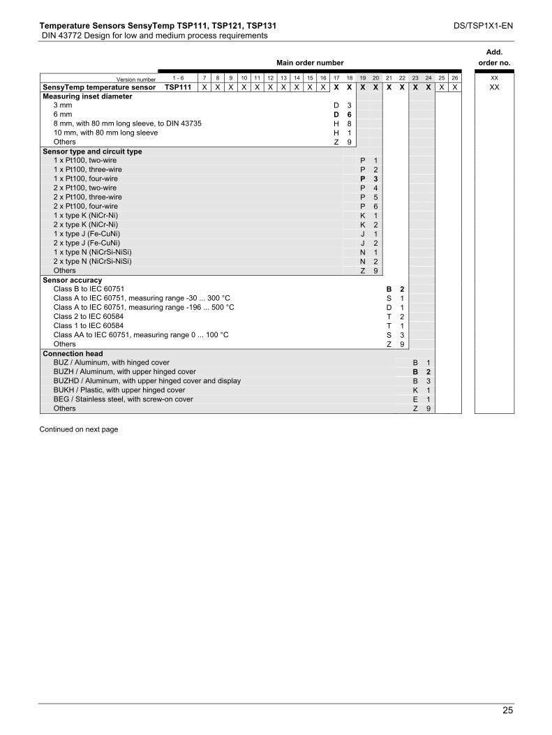
Temperature Sensors SensyTemp TSP111, TSP121, TSP131 DS/TSP1X1-EN DIN 43772 Design for low and medium process requirements
25
Main order number
Add. order no.
Version number 1 - 6 7 8 9 10 11 12 13 14 15 16 17 18 19 20 21 22 23 24 25 26 XX
SensyTemp temperature sensor TSP111 X X X X X X X X X X X X X X X X X X X X XX Measuring inset diameter
3 mm D 3 6 mm D 6 8 mm, with 80 mm long sleeve, to DIN 43735 H 8 10 mm, with 80 mm long sleeve H 1 Others Z 9 Sensor type and circuit type
1 x Pt100, two-wire P 1 1 x Pt100, three-wire P 2 1 x Pt100, four-wire P 3 2 x Pt100, two-wire P 4 2 x Pt100, three-wire P 5 2 x Pt100, four-wire P 6 1 x type K (NiCr-Ni) K 1 2 x type K (NiCr-Ni) K 2 1 x type J (Fe-CuNi) J 1 2 x type J (Fe-CuNi) J 2 1 x type N (NiCrSi-NiSi) N 1 2 x type N (NiCrSi-NiSi) N 2 Others Z 9 Sensor accuracy
Class B to IEC 60751 B 2 Class A to IEC 60751, measuring range -30 ... 300 °C S 1 Class A to IEC 60751, measuring range -196 ... 500 °C D 1 Class 2 to IEC 60584 T 2 Class 1 to IEC 60584 T 1 Class AA to IEC 60751, measuring range 0 ... 100 °C S 3 Others Z 9 Connection head
BUZ / Aluminum, with hinged cover B 1 BUZH / Aluminum, with upper hinged cover B 2 BUZHD / Aluminum, with upper hinged cover and display B 3 BUKH / Plastic, with upper hinged cover K 1 BEG / Stainless steel, with screw-on cover E 1 Others Z 9 Continued on next page
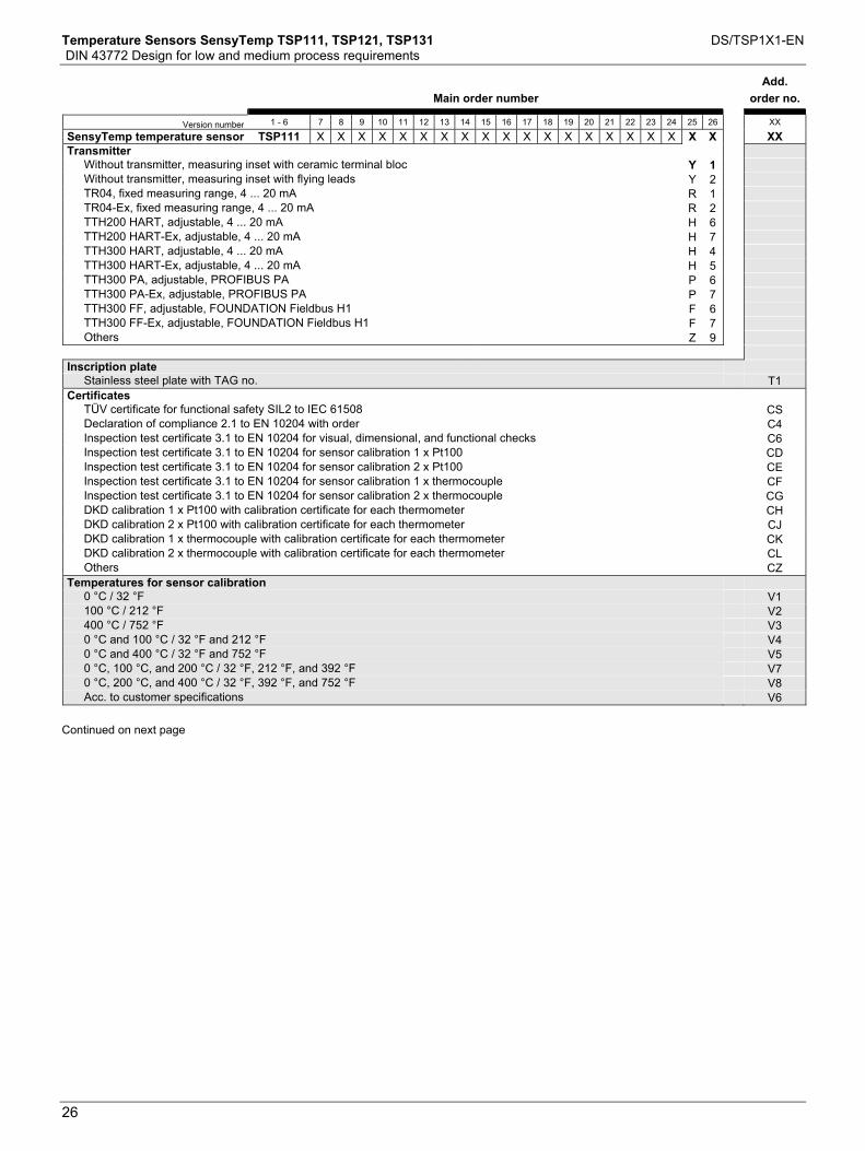
Temperature Sensors SensyTemp TSP111, TSP121, TSP131 DS/TSP1X1-EN DIN 43772 Design for low and medium process requirements
26
Main order number
Add. order no.
Version number 1 - 6 7 8 9 10 11 12 13 14 15 16 17 18 19 20 21 22 23 24 25 26 XX
SensyTemp temperature sensor TSP111 X X X X X X X X X X X X X X X X X X X X XX Transmitter
Without transmitter, measuring inset with ceramic terminal bloc Y 1 Without transmitter, measuring inset with flying leads Y 2 TR04, fixed measuring range, 4 ... 20 mA R 1 TR04-Ex, fixed measuring range, 4 ... 20 mA R 2 TTH200 HART, adjustable, 4 ... 20 mA H 6 TTH200 HART-Ex, adjustable, 4 ... 20 mA H 7 TTH300 HART, adjustable, 4 ... 20 mA H 4 TTH300 HART-Ex, adjustable, 4 ... 20 mA H 5 TTH300 PA, adjustable, PROFIBUS PA P 6 TTH300 PA-Ex, adjustable, PROFIBUS PA P 7 TTH300 FF, adjustable, FOUNDATION Fieldbus H1 F 6 TTH300 FF-Ex, adjustable, FOUNDATION Fieldbus H1 F 7 Others Z 9 Inscription plate
Stainless steel plate with TAG no. T1 Certificates
TÜV certificate for functional safety SIL2 to IEC 61508 CS Declaration of compliance 2.1 to EN 10204 with order C4 Inspection test certificate 3.1 to EN 10204 for visual, dimensional, and functional checks C6 Inspection test certificate 3.1 to EN 10204 for sensor calibration 1 x Pt100 CD Inspection test certificate 3.1 to EN 10204 for sensor calibration 2 x Pt100 CE Inspection test certificate 3.1 to EN 10204 for sensor calibration 1 x thermocouple CF Inspection test certificate 3.1 to EN 10204 for sensor calibration 2 x thermocouple CG DKD calibration 1 x Pt100 with calibration certificate for each thermometer CH DKD calibration 2 x Pt100 with calibration certificate for each thermometer CJ DKD calibration 1 x thermocouple with calibration certificate for each thermometer CK DKD calibration 2 x thermocouple with calibration certificate for each thermometer CL Others CZ Temperatures for sensor calibration
0 °C / 32 °F V1 100 °C / 212 °F V2 400 °C / 752 °F V3 0 °C and 100 °C / 32 °F and 212 °F V4 0 °C and 400 °C / 32 °F and 752 °F V5 0 °C, 100 °C, and 200 °C / 32 °F, 212 °F, and 392 °F V7 0 °C, 200 °C, and 400 °C / 32 °F, 392 °F, and 752 °F V8 Acc. to customer specifications V6 Continued on next page
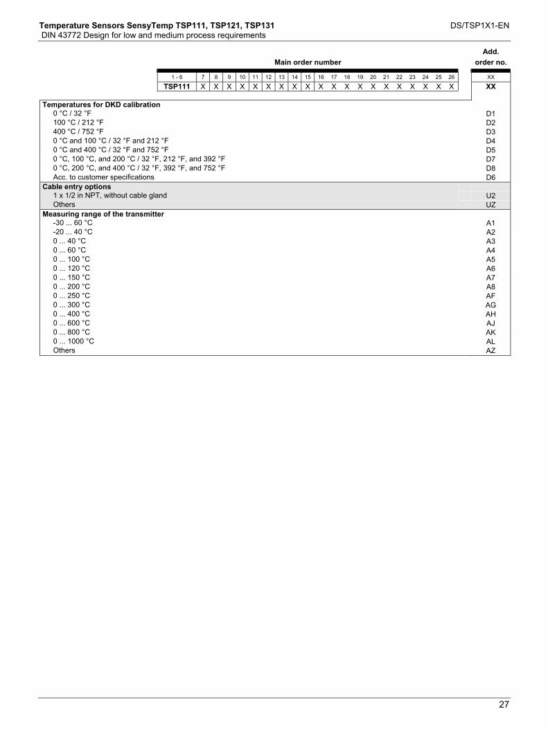
Temperature Sensors SensyTemp TSP111, TSP121, TSP131 DS/TSP1X1-EN DIN 43772 Design for low and medium process requirements
27
Main order number
Add. order no.
1 - 6 7 8 9 10 11 12 13 14 15 16 17 18 19 20 21 22 23 24 25 26 XX
TSP111 X X X X X X X X X X X X X X X X X X X X XX Temperatures for DKD calibration
0 °C / 32 °F D1 100 °C / 212 °F D2 400 °C / 752 °F D3 0 °C and 100 °C / 32 °F and 212 °F D4 0 °C and 400 °C / 32 °F and 752 °F D5 0 °C, 100 °C, and 200 °C / 32 °F, 212 °F, and 392 °F D7 0 °C, 200 °C, and 400 °C / 32 °F, 392 °F, and 752 °F D8 Acc. to customer specifications D6 Cable entry options
1 x 1/2 in NPT, without cable gland U2 Others UZ Measuring range of the transmitter
-30 ... 60 °C A1 -20 ... 40 °C A2 0 ... 40 °C A3 0 ... 60 °C A4 0 ... 100 °C A5 0 ... 120 °C A6 0 ... 150 °C A7 0 ... 200 °C A8 0 ... 250 °C AF 0 ... 300 °C AG 0 ... 400 °C AH 0 ... 600 °C AJ 0 ... 800 °C AK 0 ... 1000 °C AL Others AZ
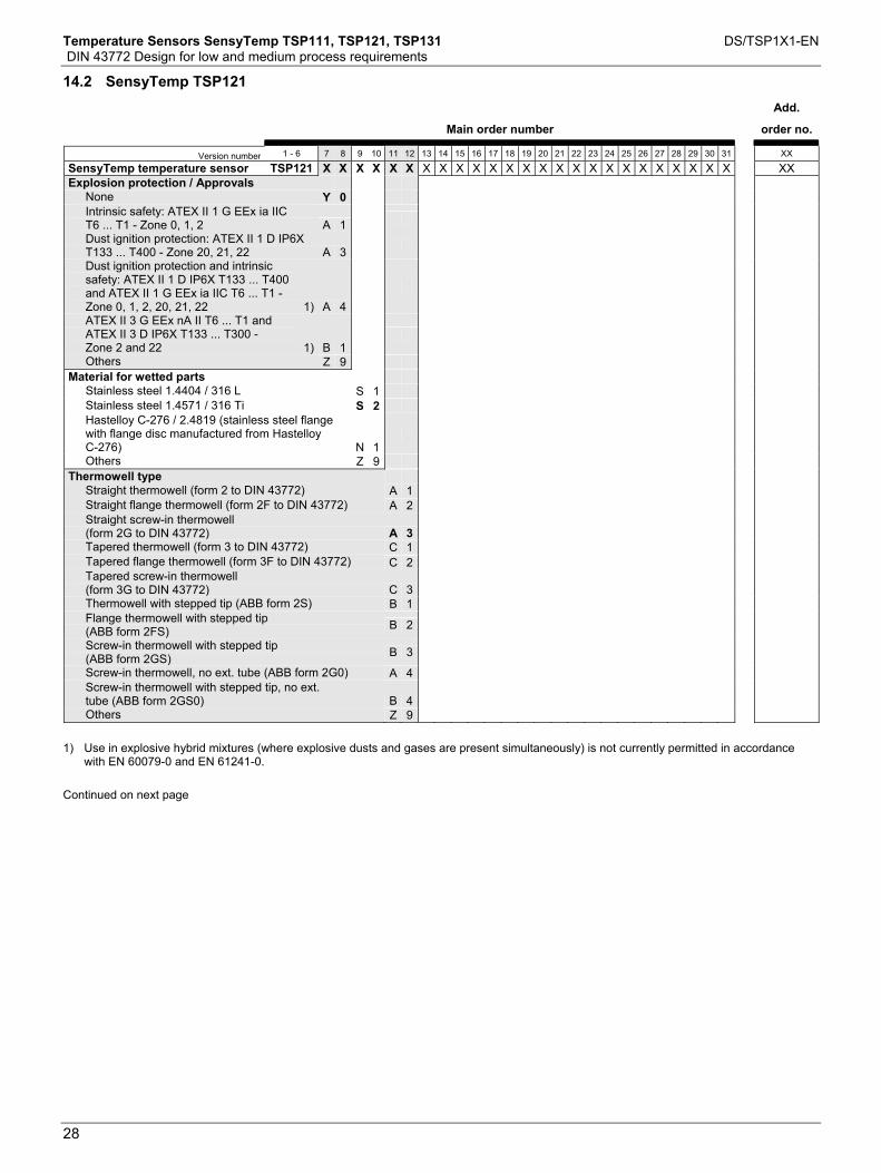
Temperature Sensors SensyTemp TSP111, TSP121, TSP131 DS/TSP1X1-EN DIN 43772 Design for low and medium process requirements
28
14.2 SensyTemp TSP121
Main order number
Add.
order no.
Version number 1 - 6 7 8 9 10 11 12 13 14 15 16 17 18 19 20 21 22 23 24 25 26 27 28 29 30 31 XX
SensyTemp temperature sensor TSP121 X X X X X X X X X X X X X X X X X X X X X X X X X XX Explosion protection / Approvals
None Y 0 Intrinsic safety: ATEX II 1 G EEx ia IIC
T6 ... T1 - Zone 0, 1, 2 A 1 Dust ignition protection: ATEX II 1 D IP6X
T133 ... T400 - Zone 20, 21, 22 A 3 Dust ignition protection and intrinsic
safety: ATEX II 1 D IP6X T133 ... T400 and ATEX II 1 G EEx ia IIC T6 ... T1 - Zone 0, 1, 2, 20, 21, 22 1) A 4
ATEX II 3 G EEx nA II T6 ... T1 and ATEX II 3 D IP6X T133 ... T300 - Zone 2 and 22 1) B 1
Others Z 9 Material for wetted parts
Stainless steel 1.4404 / 316 L S 1 Stainless steel 1.4571 / 316 Ti S 2 Hastelloy C-276 / 2.4819 (stainless steel flange
with flange disc manufactured from Hastelloy C-276) N 1
Others Z 9 Thermowell type
Straight thermowell (form 2 to DIN 43772) A 1 Straight flange thermowell (form 2F to DIN 43772) A 2 Straight screw-in thermowell
(form 2G to DIN 43772) A 3 Tapered thermowell (form 3 to DIN 43772) C 1 Tapered flange thermowell (form 3F to DIN 43772) C 2 Tapered screw-in thermowell
(form 3G to DIN 43772) C 3 Thermowell with stepped tip (ABB form 2S) B 1 Flange thermowell with stepped tip
(ABB form 2FS) B 2 Screw-in thermowell with stepped tip
(ABB form 2GS) B 3 Screw-in thermowell, no ext. tube (ABB form 2G0) A 4 Screw-in thermowell with stepped tip, no ext.
tube (ABB form 2GS0) B 4 Others Z 9 1) Use in explosive hybrid mixtures (where explosive dusts and gases are present simultaneously) is not currently permitted in accordance
with EN 60079-0 and EN 61241-0. Continued on next page

Temperature Sensors SensyTemp TSP111, TSP121, TSP131 DS/TSP1X1-EN DIN 43772 Design for low and medium process requirements
29
Main order number
Add.
order no.
Version number 1 - 6 7 8 9 10 11 12 13 14 15 16 17 18 19 20 21 22 23 24 25 26 27 28 29 30 31 XX
SensyTemp temperature sensor TSP121 X X X X X X X X X X X X X X X X X X X X X X X X X XX Process connection
Without process connection Y 0 0 Adjustable compression fitting G 1/2 A A 0 1 Adjustable compression fitting 1/2 NPT A 0 2 Parallel screw-in thread G 1/2 A S 0 1 Parallel screw-in thread G 3/4 A S 0 2 Parallel screw-in thread G 1 A S 0 3 Tapered screw-in thread 1/2 NPT S 0 4 Tapered screw-in thread 3/4 NPT S 0 5 Tapered screw-in thread 1 NPT S 0 6 Parallel screw-in thread M20 x 1.5 S 0 7 Parallel screw-in thread M27 x 2 S 0 8 Tapered screw-in thread 1/2 BSPT S 0 9 Tapered screw-in thread 3/4 BSPT S 1 0 Tapered screw-in thread 1 BSPT S 1 1 Flange DN25 PN10 ... PN40, to EN 1092-1 F 0 3 Flange DN40 PN10 ... PN40, to EN 1092-1 F 0 4 Flange DN50 PN10 ... PN40, to EN 1092-1 F 0 5 Flange 1 in 150 lbs, to ANSI/ASME B16.5 F 0 7 Flange 1 in 300 lbs, to ANSI/ASME B16.5 F 0 8 Flange 1.5 in 150 lbs, to ANSI/ASME B16.5 F 1 1 Flange 1.5 in 300 lbs, to ANSI/ASME B16.5 F 1 2 Flange 1.5 in 600 lbs, to ANSI/ASME B16.5 F 1 3 Flange 2 in 150 lbs, to ANSI/ASME B16.5 F 1 5 Flange 2 in 300 lbs, to ANSI/ASME B16.5 F 1 6 Flange 2 in 600 lbs, to ANSI/ASME B16.5 F 1 7 Tri-Clamp flange 1 in ... 1.5 in, ISO 2852 DN15 ... DN25 /
DIN 32676 DN25 ... DN40 / BS 4825 T 0 1 Tri-Clamp flange 2 in, ISO 2852 DN32 ... DN40 / DIN 32676
DN50 / BS 4825 T 0 2 Tri-Clamp flange 2.5 in, ISO 2852 DN50 / BS 4825 T 0 3 Tri-Clamp flange 3 in, ISO 2852 DN65 / DIN 32676 DN65 /
BS 4825 T 0 4 Tri-Clamp flange 4 in, DIN 32676 DN100 / BS 4825 T 0 5 Others Z 9 9 Thermowell diameter
9 mm A 1 11 mm A 2 12 mm A 3 14 mm A 4 13,7 mm B 2 Others Z 9 Continued on next page

Temperature Sensors SensyTemp TSP111, TSP121, TSP131 DS/TSP1X1-EN DIN 43772 Design for low and medium process requirements
30
Main order number
Add.
order no.
Version number 1 - 6 7 8 9 10 11 12 13 14 15 16 17 18 19 20 21 22 23 24 25 26 27 28 29 30 31 XX
SensyTemp temperature sensor TSP121 X X X X X X X X X X X X X X X X X X X X X X X X X XX Insertion length U
No fixed installation length Y 0 U = 100 mm U 1 U = 160 mm U 3 U = 250 mm U 5 U = 400 mm U 7 Acc. to customer requirements Z 9 Nominal length N
N = 230 mm N 1 N = 290 mm N 3 N = 380 mm N 5 N = 530 mm N 7 Acc. to customer requirements Z 9 Measuring inset type
Basic version, thin film measurement resistor, measuring range -50 ... 400 °C, vibration resistance 10 g S 1
Resistance thermometer, thin film measurement resistor, measuring range -50 ... 400 °C, vibration resistance 60 g S 2
Resistance thermometer, extended measuring range -196 … 600 °C, wire-wound measurement resistor, vibration resistance 10 g D 1
Resistance thermometer, extended measuring range -196 … 600 °C, wire-wound measurement resistor, vibration resistance 3 g D 2
Thermocouple T 1 Others Z 9 Sensor type and circuit type
1 x Pt100, two-wire P 1 1 x Pt100, three-wire P 2 1 x Pt100, four-wire P 3 2 x Pt100, two-wire P 4 2 x Pt100, three-wire P 5 2 x Pt100, four-wire P 6 1 x type K (NiCr-Ni) K 1 2 x type K (NiCr-Ni) K 2 1 x type J (Fe-CuNi) J 1 2 x type J (Fe-CuNi) J 2 1 x type N (NiCrSi-NiSi) N 1 2 x type N (NiCrSi-NiSi) N 2 Others Z 9 Continued on next page

Temperature Sensors SensyTemp TSP111, TSP121, TSP131 DS/TSP1X1-EN DIN 43772 Design for low and medium process requirements
31
Main order number
Add.
order no.
Version number 1 - 6 7 8 9 10 11 12 13 14 15 16 17 18 19 20 21 22 23 24 25 26 27 28 29 30 31 XX
SensyTemp temperature sensor TSP121 X X X X X X X X X X X X X X X X X X X X X X X X X XX Sensor accuracy
Class B to IEC 60751 B 2 Class A to IEC 60751, measuring range -30 ... 300 °C S 1 Class A to IEC 60751, measuring range -196 ... 500 °C D 1 Class 2 to IEC 60584 T 2 Class 1 to IEC 60584 T 1 Class AA to IEC 60751, measuring range 0 ... 100 °C S 3 Others Z 9 Connection head
BUZ / Aluminum, with hinged cover B 1 BUZH / Aluminum, with upper hinged cover B 2 BUZHD / Aluminum, with upper hinged cover and display B 3 BUKH / Plastic, with upper hinged cover K 1 BEG / Stainless steel, with screw-on cover E 1 Others Z 9 Transmitter
Without transmitter, measuring inset with terminal bloc Y 1 Without transmitter, measuring inset with flying leads Y 2 TR04, fixed measuring range, 4 ... 20 mA R 1 TR04-Ex, fixed measuring range, 4 ... 20 mA R 2 TTH200 HART, adjustable, 4 ... 20 mA H 6 TTH200 HART-Ex, adjustable, 4 ... 20 mA H 7 TTH300 HART, adjustable, 4 ... 20 mA H 4 TTH300 HART-Ex, adjustable, 4 ... 20 mA H 5 TTH300 PA, adjustable, PROFIBUS PA P 6 TTH300 PA-Ex, adjustable, PROFIBUS PA P 7 TTH300 FF, adjustable, FOUNDATION Fieldbus H1 F 6 TTH300 FF-Ex, adjustable, FOUNDATION Fieldbus H1 F 7 Others Z 9 Continued on next page

Temperature Sensors SensyTemp TSP111, TSP121, TSP131 DS/TSP1X1-EN DIN 43772 Design for low and medium process requirements
32
Main order number
Add.
order no.
1 - 6 7 8 9 10 11 12 13 14 15 16 17 18 19 20 21 22 23 24 25 26 27 28 29 30 31 XX
TSP121 X X X X X X X X X X X X X X X X X X X X X X X X X XX Name plate
Stainless steel plate with TAG no. T1 Certificates
TÜV certificate for functional safety SIL2 to IEC 61508 CS Inspection test certificate 3.1 to EN 10204 material confirmation for wetted parts C2 Declaration of compliance 2.1 to EN 10204 for order conformity C4 Inspection test certificate 3.1 to EN 10204 for visual, dimensional, and functional checks C6 Inspection test certificate 3.1 to EN 10204 for helium leak test C7 Inspection test certificate 3.1 to EN 10204 for x-ray inspection C8 Inspection test certificate 3.1 to EN 10204 for dye penetration test C9 Inspection test certificate 3.1 to EN 10204 for compression test of thermowell CB Inspection test certificate 3.1 to EN 10204 for sensor calibration 1 x Pt100 CD Inspection test certificate 3.1 to EN 10204 for sensor calibration 2 x Pt100 CE Inspection test certificate 3.1 to EN 10204 for sensor calibration 1 x thermocouple CF Inspection test certificate 3.1 to EN 10204 for sensor calibration 2 x thermocouple CG DKD calibration 1 x Pt100 with calibration certificate for each thermometer CH DKD calibration 2 x Pt100 with calibration certificate for each thermometer CJ DKD calibration 1 x thermocouple with calibration certificate for each thermometer CK DKD calibration 2 x thermocouple with calibration certificate for each thermometer CL Others CZ Temperatures for sensor calibration
0 °C / 32 °F V1 100 °C / 212 °F V2 400 °C / 752 °F V3 0 °C and 100 °C / 32 °F and 212 °F V4 0 °C and 400 °C / 32 °F and 752 °F V5 0 °C, 100 °C, and 200 °C / 32 °F, 212 °F, and 392 °F V7 0 °C, 200 °C, and 400 °C / 32 °F, 392 °F, and 752 °F V8 Acc. to customer specifications V6 Temperatures for DKD calibration
0 °C / 32 °F D1 100 °C / 212 °F D2 400 °C / 752 °F D3 0 °C and 100 °C / 32 °F and 212 °F D4 0 °C and 400 °C / 32 °F and 752 °F D5 0 °C, 100 °C, and 200 °C / 32 °F, 212 °F, and 392 °F D7 0 °C, 200 °C, and 400 °C / 32 °F, 392 °F, and 752 °F D8 Acc. to customer specifications D6 Continued on next page
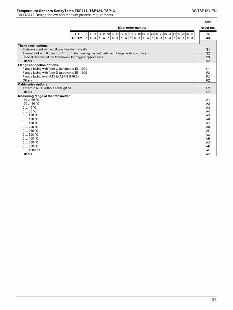
Temperature Sensors SensyTemp TSP111, TSP121, TSP131 DS/TSP1X1-EN DIN 43772 Design for low and medium process requirements
33
Main order number
Add.
order no.
1 - 6 7 8 9 10 11 12 13 14 15 16 17 18 19 20 21 22 23 24 25 26 27 28 29 30 31 XX
TSP121 X X X X X X X X X X X X X X X X X X X X X X X X X XX Thermowell options
Stainless steel with additional tantalum sheath S1 Thermowell with 0.5 mm E-CTFE / Halar coating, wetted parts incl. flange sealing surface S2 Special cleaning of the thermowell for oxygen applications S9 Others SZ Flange connection options
Flange facing with form C (tongue) to EN 1092 F1 Flange facing with form D (groove) to EN 1092 F2 Flange facing form RTJ to ASME B16.5v F3 Others FZ Cable entry options
1 x 1/2 in NPT, without cable gland U2 Others UZ Measuring range of the transmitter
-30 ... 60 °C A1 -20 ... 40 °C A2 0 ... 40 °C A3 0 ... 60 °C A4 0 ... 100 °C A5 0 ... 120 °C A6 0 ... 150 °C A7 0 ... 200 °C A8 0 ... 250 °C AF 0 ... 300 °C AG 0 ... 400 °C AH 0 ... 600 °C AJ 0 ... 800 °C AK 0 ... 1000 °C AL Others AZ
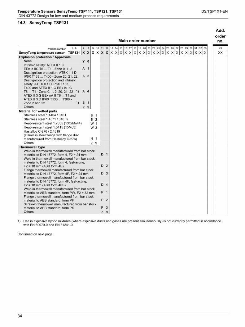
Temperature Sensors SensyTemp TSP111, TSP121, TSP131 DS/TSP1X1-EN DIN 43772 Design for low and medium process requirements
34
14.3 SensyTemp TSP131
Main order number
Add. order no.
Version number 1 - 6 7 8 9 10 11 12 13 14 15 16 17 18 19 20 21 22 23 24 25 26 27 28 29 30 31 32 33 XX
SensyTemp temperature sensor TSP131 X X X X X X X X X X X X X X X X X X X X X X X X X X X XX Explosion protection / Approvals
None Y 0 Intrinsic safety: ATEX II 1 G
EEx ia IIC T6 ... T1 - Zone 0, 1, 2 A 1
Dust ignition protection: ATEX II 1 D IP6X T133 ... T400 - Zone 20, 21, 22 A 3
Dust ignition protection and intrinsic safety: ATEX II 1 D IP6X T133 ... T400 and ATEX II 1 G EEx ia IIC T6 ... T1 - Zone 0, 1, 2, 20, 21, 22 1) A 4
ATEX II 3 G EEx nA II T6 ... T1 and ATEX II 3 D IP6X T133 ... T300 - Zone 2 and 22 1) B 1
Others Z 9 Material for wetted parts
Stainless steel 1.4404 / 316 L S 1 Stainless steel 1.4571 / 316 Ti S 2 Heat-resistant steel 1.7335 (13CrMo44) W 1 Heat-resistant steel 1.5415 (15Mo3) W 3 Hastelloy C-276 / 2.4819
(stainless steel flange with flange disc manufactured from Hastelloy C-276) N 1
Others Z 9 Thermowell type
Weld-in thermowell manufactured from bar stock material to DIN 43772, form 4, F2 = 24 mm D 1
Weld-in thermowell manufactured from bar stock material to DIN 43772, form 4, fast-acting, F2 = 18 mm (ABB form 4S) D 2
Flange thermowell manufactured from bar stock material to DIN 43772, form 4F, F2 = 24 mm D 3
Flange thermowell manufactured from bar stock material to DIN 43772, form 4F, fast-acting, F2 = 18 mm (ABB form 4FS) D 4
Weld-in thermowell manufactured from bar stock material to ABB standard, form PW, F2 = 32 mm P 1
Flange thermowell manufactured from bar stock material to ABB standard, form PF P 2
Screw-in thermowell manufactured from bar stock material to ABB standard, form PS P 3
Others Z 9 1) Use in explosive hybrid mixtures (where explosive dusts and gases are present simultaneously) is not currently permitted in accordance
with EN 60079-0 and EN 61241-0. Continued on next page

Temperature Sensors SensyTemp TSP111, TSP121, TSP131 DS/TSP1X1-EN DIN 43772 Design for low and medium process requirements
35
Main order number
Add.
order no.
Version number 1 - 6 7 8 9 10 11 12 13 14 15 16 17 18 19 20 21 22 23 24 25 26 27 28 29 30 31 32 33 XX
SensyTemp temperature sensor TSP131 X X X X X X X X X X X X X X X X X X X X X X X X X X X XX
Process connection Without process connection Y 0 0 Tapered screw-in thread 1/2 NPT S 0 4 Tapered screw-in thread 3/4 NPT S 0 5 Tapered screw-in thread 1 NPT S 0 6 Flange DN25 PN10 ... PN40, to EN 1092-1 F 0 3 Flange DN40 PN10 ... PN40, to EN 1092-1 F 0 4 Flange DN50 PN10 ... PN40, to EN 1092-1 F 0 5 Flange 1 in 150 lbs, to ANSI/ASME B16.5 F 0 7 Flange 1 in 300 lbs, to ANSI/ASME B16.5 F 0 8 Flange 1.5 in 150 lbs, to ANSI/ASME B16.5 F 1 1 Flange 1.5 in 300 lbs, to ANSI/ASME B16.5 F 1 2 Flange 1.5 in 600 lbs, to ANSI/ASME B16.5 F 1 3 Flange 2 in 150 lbs, to ANSI/ASME B16.5 F 1 5 Flange 2 in 300 lbs, to ANSI/ASME B16.5 F 1 6 Flange 2 in 600 lbs, to ANSI/ASME B16.5 F 1 7 Tri-Clamp flange 1 in ... 1.5 in, ISO 2852
DN15 ... DN25 / DIN 32676 DN25 ... DN40 / BS 4825 T 0 1
Tri-Clamp flange 2 in, ISO 2852 DN32 ... DN40 / DIN 32676 DN50 / BS 4825 T 0 2
Tri-Clamp flange 2.5 in, ISO 2852 DN50 / BS 4825 T 0 3 Tri-Clamp flange 3 in, ISO 2852 DN65 / DIN 32676 DN65 /
BS 4825 T 0 4
Tri-Clamp flange 4 in, DIN 32676 DN100 / BS 4825 T 0 5 Others Z 9 9 Extension length K
150 mm K 1 Variable ext. tube length Z 9 Thermowell connection
Parallel screw-in thread M14 x 1.5 M 1 Parallel screw-in thread M18 x 1.5 M 2 Tapered screw-in thread 1/2 NPT N 1 1/2 in NPT - 1/2 in NPT, not separable N 2 1/2 in NPT - 1/2 in NPT, separable N 3 Others Z 9 Continued on next page

Temperature Sensors SensyTemp TSP111, TSP121, TSP131 DS/TSP1X1-EN DIN 43772 Design for low and medium process requirements
36
Main order number
Add.
order no.
Version number 1 - 6 7 8 9 10 11 12 13 14 15 16 17 18 19 20 21 22 23 24 25 26 27 28 29 30 31 32 33 XX
SensyTemp temperature sensor TSP131 X X X X X X X X X X X X X X X X X X X X X X X X X X X XX
Insertion length U No fixed length Y 0 U = 130 mm D 1 U = 190 mm D 2 U = 340 mm D 3 U = 100 mm P 1 U = 150 mm P 2 U = 200 mm P 3 U = 250 mm P 4 U = 300 mm P 5 U = 350 mm P 6 Acc. to customer requirements Z 9 Thermowell length L
L = 110 mm, C = 65 mm D 1 L = 140 mm, C = 65 mm D 3 L = 200 mm, C = 65 mm D 4 L = 200 mm, C = 125 mm D 5 L = 260 mm, C = 125 mm D 6 L = 410 mm, C = 275 mm D 7 To ABB standard (insertion depth + 65 mm) P 1 Acc. to customer requirements Z 9 Measuring inset type
Basic version, thin film measurement resistor, measuring range -50 ... 400 °C, vibration resistance 10 g S 1
Increased vibration resistance, thin film measurement resistor, measuring range -50 ... 400 °C, vibration resistance 60 g S 2
Extended measuring range -196 ... 600 °C, wire-wound measurement resistor, vibration resistance 10 g D 1
Extended measuring range -196 ... 600 °C, wire-wound measurement resistor, vibration resistance 3 g D 2
Thermocouple T 1 Others Z 9 Sensor type and circuit type
1 x Pt100, two-wire P 1 1 x Pt100, three-wire P 2 1 x Pt100, four-wire P 3 2 x Pt100, two-wire P 4 2 x Pt100, three-wire P 5 2 x Pt100, four-wire P 6 1 x type K (NiCr-Ni) K 1 2 x type K (NiCr-Ni) K 2 1 x type J (Fe-CuNi) J 1 2 x type J (Fe-CuNi) J 2 1 x type N (NiCrSi-NiSi) N 1 2 x type N (NiCrSi-NiSi) N 2 Others Z 9 Continued on next page
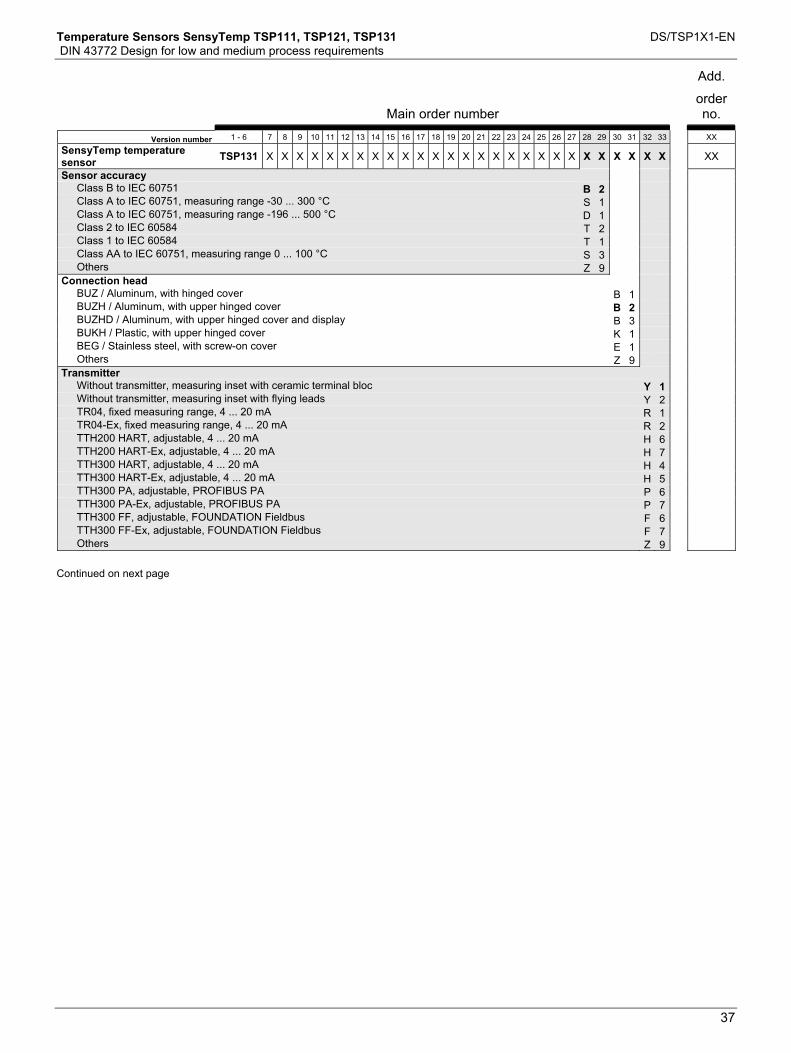
Temperature Sensors SensyTemp TSP111, TSP121, TSP131 DS/TSP1X1-EN DIN 43772 Design for low and medium process requirements
37
Main order number
Add.
order no.
Version number 1 - 6 7 8 9 10 11 12 13 14 15 16 17 18 19 20 21 22 23 24 25 26 27 28 29 30 31 32 33 XX
SensyTemp temperature sensor TSP131 X X X X X X X X X X X X X X X X X X X X X X X X X X X XX
Sensor accuracy Class B to IEC 60751 B 2 Class A to IEC 60751, measuring range -30 ... 300 °C S 1 Class A to IEC 60751, measuring range -196 ... 500 °C D 1 Class 2 to IEC 60584 T 2 Class 1 to IEC 60584 T 1 Class AA to IEC 60751, measuring range 0 ... 100 °C S 3 Others Z 9 Connection head
BUZ / Aluminum, with hinged cover B 1 BUZH / Aluminum, with upper hinged cover B 2 BUZHD / Aluminum, with upper hinged cover and display B 3 BUKH / Plastic, with upper hinged cover K 1 BEG / Stainless steel, with screw-on cover E 1 Others Z 9 Transmitter
Without transmitter, measuring inset with ceramic terminal bloc Y 1 Without transmitter, measuring inset with flying leads Y 2 TR04, fixed measuring range, 4 ... 20 mA R 1 TR04-Ex, fixed measuring range, 4 ... 20 mA R 2 TTH200 HART, adjustable, 4 ... 20 mA H 6 TTH200 HART-Ex, adjustable, 4 ... 20 mA H 7 TTH300 HART, adjustable, 4 ... 20 mA H 4 TTH300 HART-Ex, adjustable, 4 ... 20 mA H 5 TTH300 PA, adjustable, PROFIBUS PA P 6 TTH300 PA-Ex, adjustable, PROFIBUS PA P 7 TTH300 FF, adjustable, FOUNDATION Fieldbus F 6 TTH300 FF-Ex, adjustable, FOUNDATION Fieldbus F 7 Others Z 9 Continued on next page
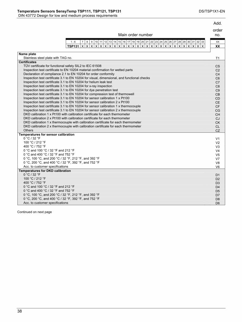
Temperature Sensors SensyTemp TSP111, TSP121, TSP131 DS/TSP1X1-EN DIN 43772 Design for low and medium process requirements
38
Main order number
Add.
order no.
1 - 6 7 8 9 10 11 12 13 14 15 16 17 18 19 20 21 22 23 24 25 26 27 28 29 30 31 32 33 XX
TSP131 X X X X X X X X X X X X X X X X X X X X X X X X X X X XX
Name plate Stainless steel plate with TAG no. T1Certificates
TÜV certificate for functional safety SIL2 to IEC 61508 CS Inspection test certificate to EN 10204 material confirmation for wetted parts C2 Declaration of compliance 2.1 to EN 10204 for order conformity C4 Inspection test certificate 3.1 to EN 10204 for visual, dimensional, and functional checks C6 Inspection test certificate 3.1 to EN 10204 for helium leak test C7 Inspection test certificate 3.1 to EN 10204 for x-ray inspection C8 Inspection test certificate 3.1 to EN 10204 for dye penetration test C9 Inspection test certificate 3.1 to EN 10204 for compression test of thermowell CB Inspection test certificate 3.1 to EN 10204 for sensor calibration 1 x Pt100 CD Inspection test certificate 3.1 to EN 10204 for sensor calibration 2 x Pt100 CE Inspection test certificate 3.1 to EN 10204 for sensor calibration 1 x thermocouple CF Inspection test certificate 3.1 to EN 10204 for sensor calibration 2 x thermocouple CG DKD calibration 1 x Pt100 with calibration certificate for each thermometer CH DKD calibration 2 x Pt100 with calibration certificate for each thermometer CJ DKD calibration 1 x thermocouple with calibration certificate for each thermometer CK DKD calibration 2 x thermocouple with calibration certificate for each thermometer CL Others CZTemperatures for sensor calibration
0 °C / 32 °F V1 100 °C / 212 °F V2 400 °C / 752 °F V3 0 °C and 100 °C / 32 °F and 212 °F V4 0 °C and 400 °C / 32 °F and 752 °F V5 0 °C, 100 °C, and 200 °C / 32 °F, 212 °F, and 392 °F V7 0 °C, 200 °C, and 400 °C / 32 °F, 392 °F, and 752 °F V8 Acc. to customer specifications V6Temperatures for DKD calibration
0 °C / 32 °F D1 100 °C / 212 °F D2 400 °C / 752 °F D3 0 °C and 100 °C / 32 °F and 212 °F D4 0 °C and 400 °C / 32 °F and 752 °F D5 0 °C, 100 °C, and 200 °C / 32 °F, 212 °F, and 392 °F D7 0 °C, 200 °C, and 400 °C / 32 °F, 392 °F, and 752 °F D8 Acc. to customer specifications D6 Continued on next page

Temperature Sensors SensyTemp TSP111, TSP121, TSP131 DS/TSP1X1-EN DIN 43772 Design for low and medium process requirements
39
Main order number
Add.
order no.
1 - 6 7 8 9 10 11 12 13 14 15 16 17 18 19 20 21 22 23 24 25 26 27 28 29 30 31 32 33 XX
TSP131 X X X X X X X X X X X X X X X X X X X X X X X X X X X XX
Thermowell options Thermowell design with tests and certificates to NACE MR 0175 S8 Special cleaning of the thermowell for oxygen applications S9 Others SZFlange connection options
Flange facing with form C (tongue) to EN 1092 F1 Flange facing with form D (groove) to EN 1092 F2 Flange facing form RTJ to ASME B16.5v F3 Flange full penetration welded F4 Others FZCable entry options
1 x 1/2 in NPT, without cable gland U2 Others UZMeasuring range of the transmitter
-30 ... 60 °C A1 -20 ... 40 °C A2 0 ... 40 °C A3 0 ... 60 °C A4 0 ... 100 °C A5 0 ... 120 °C A6 0 ... 150 °C A7 0 ... 200 °C A8 0 ... 250 °C AF 0 ... 300 °C AG 0 ... 400 °C AH 0 ... 600 °C AJ 0 ... 800 °C AK 0 ... 1000 °C AL Others AZ

Contact us
DS
/TS
P1X
1-EN
Rev
.B12
.201
0|
3KXT
1610
01R
1001ABB Ltd.
Salterbeck Trading Estate Workington, Cumbria CA14 5DS UK Phone: +44 (0)1946 830 611 Fax: +44 (0)1946 832 661 ABB Inc. 125 E. County Line Road Warminster PA 18974 USA Phone: +1 215 674 6000 Fax: +1 215 674 7183 ABB Automation Products GmbH Schillerstr. 72 32425 Minden Germany Phone: +49 551 905-534 Fax: +49 551 905-555 www.abb.com
Note We reserve the right to make technical changes or modify the contents of this document without prior notice. With regard to purchase orders, the agreed particulars shall prevail. ABB does not accept any responsibility whatsoever for potential errors or possible lack of information in this document. We reserve all rights in this document and in the subject matter and illustrations contained therein. Any reproduction, disclosure to third parties or utilization of its contents - in whole or in parts – is forbidden without prior written consent of ABB. Copyright© 2010 ABB All rights reserved

Data Sheet 10/10-3.64-EN Rev.
SensyTemp TSResistance thefor the food an
For insertion in pipelines and v
Fast response— Halftime < 2.5 s
Various designs— Sensor smooth, with threaded
or welded flange
Corrosion-resistant— Sensor and connection head m
Hygienic— Materials permissible for use wi
smooth, mounting suitable for C
Measurement m
D
HY (HY R)rmometerd beverage industries
essels
compression fitting
ade of stainless steel, IP 66
th food, surface polished IP (Cleaning In Place)
Selectable transmission of measured values— Pt 100 signal or 4 ... 20 mA with installed transmitter
High operational reliability— Components have long-term stability and are maintenance-free,
environment-resistant and vibration-resistant
Type approved— for use in milk-heating plants which require approval,
in accordance with Directive 85/357/EEC or the German Milk Executive Order (MVO)
ade easy

Resistance thermometer TSHY (SensyTemp HY R) 10/10-3.64 ENfor the food and beverage industries for insertion in pipelines and vessels
General description
The temperature sensors TSHY (SensyTemp HY R) have beendesigned, in terms of construction, choice of materials andmounting, specially for use in the food and beverage industries.
Several designs are available for mounting at measuring junc-tions. The hygienic conditions are complied with as well as therequirement of reliable cleaning using the CIP method.
Another special feature is the halftime of < 2.5 seconds. With thisshort halftime, the measurement and control tasks on the large-surface heat exchangers in these industries with their short reac-tion times are performed reliably.
The measured value can be transmitted as a Pt 100 signal or bythe installed transmitter as a 4...20 mA current signal. A pro-grammable or HART-compatible transmitter can be integratedupon request.
Sensors with installed head-mounted transmitters comply withthe EMC Directive 89/336/EEC of May 1989 and the EU Directivefor CE conformity identification.
Design and dimensions
Temperature sensor TSHY (SensyTemp HY R-1E)The typical feature of the HY R-1E sensor is its smooth polishedsensor tube with 6 mm external diameter.
The HY R-1E sensor is variable in terms of the selectable processconnector. For applications where the sensor is exposed to themedium, the immersion depth can be determined individually. Aminimum immersion depth of at least 3 to 5 times the thermowelldiameter should be observed. The immersion depth must not beless than the length of the temperature-sensitive part.
Due to the additional thermowell with weld-in type sphericalbushing the temperature sensor can be exchanged and cali-brated without the need to open the product chamber. Both thethermowell and the spherical bushing are made of stainless steeland, thus, meet all hygienic requirements and resist to processpressures up to 40 bars. Thermowells are available with insertionlengths of 50 mm and 180 mm.
The following connection options are possible for direct exposureof the HY R-1E sensor to the medium, i.e. without using a ther-mowell:
1. With threaded compression fitting G 1/4A. Made of 1.4571, with stainless steel clamping ring. For general industrial mounting. Pressure-resistant up to 40 bar.
2. With spherical bushing M12 x 1.5. Made of 1.4571, with stainless steel clamping ring. For general indus-trial mounting. Pressure-resistant up to 40 bar.
3. With spherical bushing M12 x 1.5. Made of 1.4571, PEEK clamping ring. Hygienic design. The shape of the PEEK clamping ring prevents an angular gap between the thermowell and the bushing. Pressure-resistant up to 10 bar.
4. Weld-on bushing M12 x 1.5. Made of 1.4435, PEEK clamping ring. Hygienic mounting without gap. Pres-sure-resistant up to 10 bar.
5. Collar-type bushing M12 x 1.5. Made of 1.4404. PEEK clamping ring. Hygienic mounting without gap. Pres-sure-resistant up to 10 bar.
The HY R-1E with transmitter measuring range 0...100 °C and50...100 °C is approved for use in milk-heating plants acc. MVO.
SW14
SW19
G 1/4Ø18
2712
Adjustable compressionfitting with
mounting thread
HY R-1E
Ø 60Ø 55
8
8
Ø8
46
CableglandM16x1.5
Tem
pera
ture
-sen
sitiv
e le
ngth
Nom
inal
leng
th N
Ø 17
Ø 25
SW13
17
4
Collar bushing M12 x 1.5made of 1.4404Clamping ring: PEEK
17
SW13
SW12
18.5
-0.3
Sphere Ø 25
Spherical bushing M12 x 1.5made of 1.4571Clamping ring: VA
17
SW13
Sphere Ø 25
SW12
Ø 9 x 1
U18
.5-0
.3
Sphere Ø 25
Thermowell withspherical bushing M12 x 1.5made of 1.4571Clamping ring: VA
2
5
Ø 6
Ø 29
Weld-on bushing M12 x 1.5made of 1.4435Clamping ring: PEEK
Spherical bushing M12 x 1.5made of 1.4571Clamping ring: PEEK
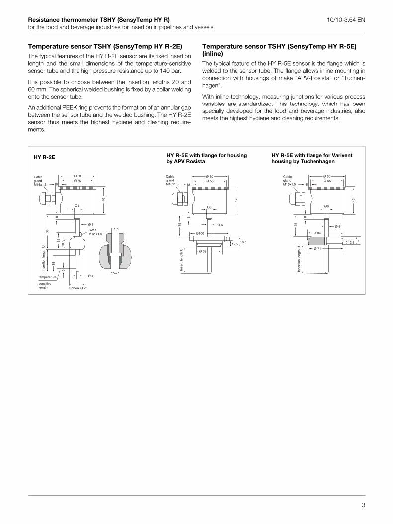
Resistance thermometer TSHY (SensyTemp HY R) 10/10-3.64 ENfor the food and beverage industries for insertion in pipelines and vessels
Temperature sensor TSHY (SensyTemp HY R-2E)The typical features of the HY R-2E sensor are its fixed insertionlength and the small dimensions of the temperature-sensitivesensor tube and the high pressure resistance up to 140 bar.
It is possible to choose between the insertion lengths 20 and60 mm. The spherical welded bushing is fixed by a collar weldingonto the sensor tube.
An additional PEEK ring prevents the formation of an annular gapbetween the sensor tube and the welded bushing. The HY R-2Esensor thus meets the highest hygiene and cleaning require-ments.
Temperature sensor TSHY (SensyTemp HY R-5E)(inline)The typical feature of the HY R-5E sensor is the flange which iswelded to the sensor tube. The flange allows inline mounting inconnection with housings of make “APV-Rosista” or “Tuchen-hagen”.
With inline technology, measuring junctions for various processvariables are standardized. This technology, which has beenspecially developed for the food and beverage industries, alsomeets the highest hygiene and cleaning requirements.
HY R-2E HY R-5E with flange for Variventhousing by Tuchenhagen
HY R-5E with flange for housingby APV Rosista
Ø 60
Ø 55
Ø 8
Ø 6
Ø 4
8
46
5
18
2918
,5
56
8
SW 13M12 x1,5
Ø 60Ø 55
Ø8
Ø 6
Ø100
Ø 69
88
75
46
12,518,5
Ø 60Ø 55
Ø8
Ø 6
Ø 84
Ø 71
8
8
75
46
12,3 19
CableglandM16x1.5
Inse
rtio
n le
ngth
U
temperature-
sensitivelength Sphere Ø 25
CableglandM16x1.5
Inse
rt.l
engt
h U
CableglandM16x1.5
Inse
rtio
n le
ngth
U
3
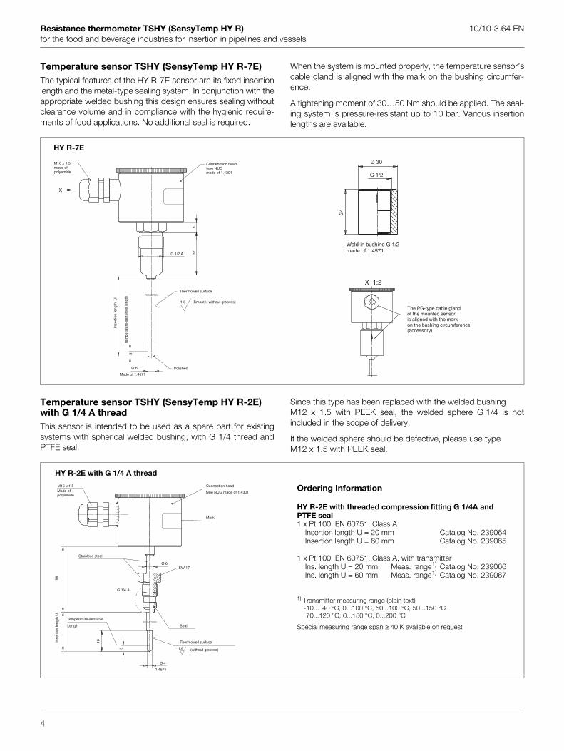
Resistance thermometer TSHY (SensyTemp HY R) 10/10-3.64 ENfor the food and beverage industries for insertion in pipelines and vessels
Temperature sensor TSHY (SensyTemp HY R-7E)The typical features of the HY R-7E sensor are its fixed insertionlength and the metal-type sealing system. In conjunction with theappropriate welded bushing this design ensures sealing withoutclearance volume and in compliance with the hygienic require-ments of food applications. No additional seal is required.
When the system is mounted properly, the temperature sensor’scable gland is aligned with the mark on the bushing circumfer-ence.
A tightening moment of 30…50 Nm should be applied. The seal-ing system is pressure-resistant up to 10 bar. Various insertionlengths are available.
Temperature sensor TSHY (SensyTemp HY R-2E) with G 1/4 A threadThis sensor is intended to be used as a spare part for existingsystems with spherical welded bushing, with G 1/4 thread andPTFE seal.
Since this type has been replaced with the welded bushing M12 x 1.5 with PEEK seal, the welded sphere G 1/4 is notincluded in the scope of delivery.
If the welded sphere should be defective, please use type M12 x 1.5 with PEEK seal.
HY R-7E
Ø 30
G 1/2
34
Weld-in bushing G 1/2made of 1.4571
5
Ø 6
1.6
G 1/2 A 378
X
M16 x 1.5made ofpolyamide
Connenction headtype NUGmade of 1.4301
Thermowell surface
(Smooth, without grooves)
Inse
rtio
n le
ngth
U
Tem
pera
ture
-sen
sitiv
e le
ngth
Polished
Made of 1.4571
X 1:2
The PG-type cable glandof the mounted sensoris aligned with the markon the bushing circumference(accessory)
HY R-2E with G 1/4 A thread
Ordering Information
HY R-2E with threaded compression fitting G 1/4A and PTFE seal1 x Pt 100, EN 60751, Class A
Insertion length U = 20 mm Catalog No. 239064Insertion length U = 60 mm Catalog No. 239065
1 x Pt 100, EN 60751, Class A, with transmitterIns. length U = 20 mm, Meas. range1) Catalog No. 239066Ins. length U = 60 mm Meas. range1) Catalog No. 239067
1) Transmitter measuring range (plain text)-10... 40 °C, 0...100 °C, 50...100 °C, 50...150 °C-70...120 °C, 0...150 °C, 0...200 °C
Special measuring range span ≥ 40 K available on request
M16 x 1.5
56
G 1/4 A
Ø 6SW 17
Made ofpolyamide
Connection head
type NUG made of 1.4301
Mark
Stainless steel
Seal
Temperature-sensitive
Length
ertio
n le
ngth
U
4
1.6
18
5
Ø 4
1.4571
Thermowell surface
(without grooves)
Ins
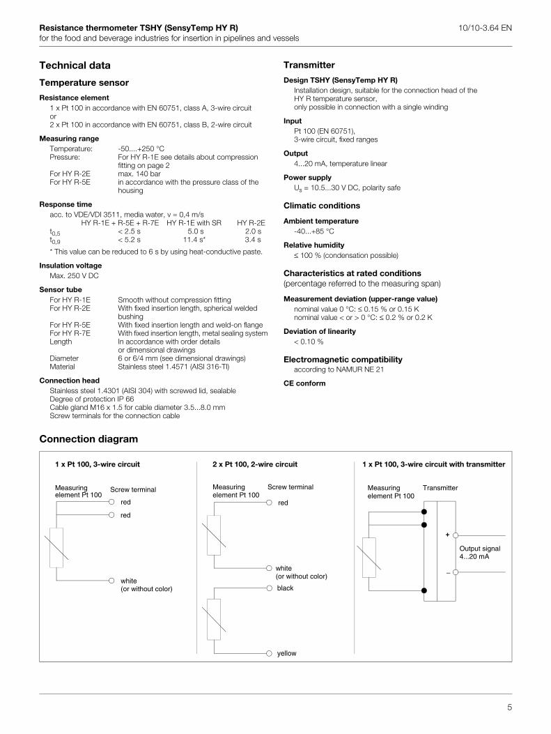
Resistance thermometer TSHY (SensyTemp HY R) 10/10-3.64 ENfor the food and beverage industries for insertion in pipelines and vessels
Technical data
Temperature sensor
Resistance element1 x Pt 100 in accordance with EN 60751, class A, 3-wire circuitor2 x Pt 100 in accordance with EN 60751, class B, 2-wire circuit
Measuring rangeTemperature: -50....+250 °CPressure: For HY R-1E see details about compression
fitting on page 2For HY R-2E max. 140 barFor HY R-5E in accordance with the pressure class of the
housing
Response timeacc. to VDE/VDI 3511, media water, v = 0,4 m/s
HY R-1E + R-5E + R-7E HY R-1E with SR HY R-2Et0,5 < 2.5 s 5.0 s 2.0 st0,9 < 5.2 s 11.4 s* 3.4 s
* This value can be reduced to 6 s by using heat-conductive paste.
Insulation voltage Max. 250 V DC
Sensor tubeFor HY R-1E Smooth without compression fittingFor HY R-2E With fixed insertion length, spherical welded
bushingFor HY R-5E With fixed insertion length and weld-on flange For HY R-7E With fixed insertion length, metal sealing systemLength In accordance with order details
or dimensional drawingsDiameter 6 or 6/4 mm (see dimensional drawings)Material Stainless steel 1.4571 (AISI 316-TI)
Connection head Stainless steel 1.4301 (AISI 304) with screwed lid, sealableDegree of protection IP 66Cable gland M16 x 1.5 for cable diameter 3.5...8.0 mmScrew terminals for the connection cable
Transmitter
Design TSHY (SensyTemp HY R)Installation design, suitable for the connection head of theHY R temperature sensor,only possible in connection with a single winding
InputPt 100 (EN 60751),3-wire circuit, fixed ranges
Output4...20 mA, temperature linear
Power supplyUs = 10.5...30 V DC, polarity safe
Climatic conditions
Ambient temperature-40...+85 °C
Relative humidity≤ 100 % (condensation possible)
Characteristics at rated conditions(percentage referred to the measuring span)
Measurement deviation (upper-range value)nominal value 0 °C: ≤ 0.15 % or 0.15 Knominal value < or > 0 °C: ≤ 0.2 % or 0.2 K
Deviation of linearity< 0.10 %
Electromagnetic compatibilityaccording to NAMUR NE 21
CE conform
Connection diagram
1 x Pt 100, 3-wire circuit 2 x Pt 100, 2-wire circuit 1 x Pt 100, 3-wire circuit with transmitter
Measuringelement Pt 100
Screw terminal
red
red
white(or without color)
Measuringelement Pt 100
Screw terminal
red
white(or without color)
black
Measuringelement Pt 100
Transmitter
Output signal4...20 mA
+
–
5
yellow

Resistance thermometer TSHY (SensyTemp HY R) 10/10-3.64 ENfor the food and beverage industries for insertion in pipelines and vessels
Ordering Information
Catalog No. EUR Deliv. timeTemperature sensor TSHY (SensyTemp HY R-1E)Sensor smooth, without threaded compression fitting1 x Pt 100, EN 60751, class A, 3-wire circuit
Sensor nominal length N = 100 mm 7963706 122,00 ex stockN = 250 mm 7963705 146,00 ex stockN = 450 mm 7963704 158,00 ex stock
2 x Pt 100, EN 60751, class B, 2-wire circuitSensor nominal length N = 100 mm 7963703 128,00 ex stock
N = 250 mm 7963702 150,00 ex stockN = 450 mm 7963701 165,00 ex stock
1 x Pt 100, EN 60751, class A, 3-wire circuitwith head mounted transmitter 4...20 mA
Sensor nominal length N = 100 mm Measuring range -10…+40 °C 7958188 195,00 2 wks.N = 100 mm Measuring range 0...100 °C 2) 7958189 195,00 2 wks.N = 100 mm Measuring range 50...100 °C 2) 7958190 195,00 2 wks.N = 100 mm Measuring range 50...150 °C 7958191 195,00 2 wks.N = 100 mm Measuring range 70...120 °C 7958192 195,00 2 wks.N = 100 mm Measuring range 0...150 °C 7958219 195,00 2 wks.N = 100 mm Measuring range 0...200 °C 7958218 195,00 2 wks.N = 100 mm Measuring range 1) 7963709 215,00 2 wks.N = 250 mm Measuring range 1) 7963708 239,00 2 wks.N = 450 mm Measuring range 1) 7963707 251,00 2 wks.
Temperature sensor TSHY (SensyTemp HY R-2E)Sensor with fixed spherical welded bushing M12 x 1,51 x Pt 100, EN 60751, class A, 3-wire circuit
Insertion length U = 20 mm 7963710 211,00 ex stockU = 60 mm 7963711 219,00 ex stock
2 x Pt 100, EN 60751, class B, 2-wire circuitInsertion length U = 20 mm 7963714 241,00 ex stock
U = 60 mm 7963715 238,00 ex stock1 x Pt 100, EN 60751, class A, 3-wire circuitwith head mounted transmitter 4...20 mA
Insertion length U = 20 mm Measuring range 1) 7963712 304,00 2 wks.U = 60 mm Measuring range 1) 7963713 312,00 2 wks.
Temperature sensor TSHY (SensyTemp HY R-5E)Sensor with fixed flange for “inline” mounting1 x Pt 100, EN 60751, class A, 3-wire circuitFlange for Varivent housing DN 40...125 by Tuchenhagen
Insertion length U = 25 mm 7963723 466,00 ex stockFlange for case DN 40...125 by APV-Rosista
Insertion length U = 25 mm 7963724 518,00 ex stock2 x Pt 100, EN 60751, class B, 2-wire circuitFlange for Varivent housing DN 40...125 by Tuchenhagen
Insertion length U = 25 mm 7963725 480,00 ex stockFlange for case DN 40...125 by APV-Rosista
Insertion length U = 25 mm 7963726 533,00 ex stock1 x Pt 100, EN 60751, class A, 3-wire circuitwith head mounted transmitter 4...20 mAFlange for Varivent housing DN 40...125 by Tuchenhagen
Insertion length U = 25 mm Measuring range 1) 7963727 541,00 2 wks.Flange for case DN 40...125 by APV-Rosista
Insertion length U = 25 mm Measuring range 1) 7963728 592,00 2 wks.
1) Measuring range of the head mounted transmitter (clear text) -10...+40 °C, 0...100 °C, 50...100 °C, 50...150 °C
6
70...120 °C, 0...150 °C, 0...200 °C2) Certfied for use in milk-heating plants acc. to MVO
Other versions on request

Resistance thermometer TSHY (SensyTemp HY R) 10/10-3.64 ENfor the food and beverage industries for insertion in pipelines and vessels
Ordering Information (continued)
Catalog No. EUR Deliv. timeTemperature sensor TSHY (SensyTemp HY R-7E)with fixed insertion length and metal-type conical nipple1 x Pt 100, EN 60751, class A, 3-wire circuit
Insertion length U = 50 mm 238380 187,00 ex stockU = 100 mm 7958106 190,00 ex stockU = 250 mm 7958107 214,00 ex stock
1 x Pt 100, EN 60751, class A, 3-wire circuit with head mounted transmitterInsertion length U = 50 mm Measuring range 0...100 °C 238376 260,00 2 wks.
U = 50 mm Measuring range 1) 238374 280,00 2 wks.U = 100 mm Measuring range 1) 238375 283,00 2 wks.U = 250 mm Measuring range 1) 241664 307,00 2 wks.
AccessoriesCatalog No. EUR Deliv. time
Mounting material for the TSHY (SensyTemp HY R-1E) sensorSpherical bushing M12 x 1.5, made of 1.4571, clamping ring made of PEEK 7963731 41,20 ex stockSpherical bushing M12 x 1.5, made of 1.4571, clamping ring made of VA 7962518 18,50 ex stockWeld-on bushing M12 x 1.5, made of 1.4435, clamping ring made of PEEK 239904 62,80 ex stockCollar bushing M12 x 1.5, made of 1.4404, clamping ring made of PEEK 240604 49,40 ex stockAdjustable threaded compression fitting G 1/4A,
made of stainless steel, clamping ring made of VA 7962519 12,40 ex stock
Thermowell with spherical bushing M12 x 1.5, made of 1.4571, clamp. ring made of VAInsertion length U = 50 mm 7963729 60,80 ex stock
U = 180 mm 7963730 104,00 ex stock
Mounting material for the TSHY (SensyTemp HY R-7E) sensorWeld-in bushing G 1/2 made of 1.4571 7958116 36,10 ex stock
1) Measuring range of the head mounted transmitter (clear text) -10...+40 °C, 0...100 °C, 50...100 °C, 50...150 °C 70...120 °C, 0...150 °C, 0...200 °C
Other versions on request
7

10/1
0-3.
64-E
N R
ev. D
09.
2013
C
APSWCUPF
AP1WUPF
APS3GPF
w
ontact us
NoteWe reserve the right to make technical changes or modify the contents of this document without prior notice. With regard to purchase orders, the agreed particulars shall prevail. ABB does not accept any responsibility whatsoever for potential errors or possible lack of information in this document.
We reserve all rights in this document and in the subject matter and illustrations contained therein. Any reproduction, disclosure to third parties or utilization of its contents – in whole or in parts – is forbidden without prior written consent of ABB.
Copyright© 2011 ABBAll rights reserved
3KXT171002R1001
Sales
BB Ltd.rocess Automationalterbeck Trading Estateorkington, CumbriaA14 5DSKhone: +44 (0)1946 830 611ax: +44 (0)1946 832 661
BB Inc.rocess Automation25 E. County Line Roadarminster PA 18974SAhone: +1 215 674 6000ax: +1 215 674 7183
BB Automation Products GmbHrocess Automationchillerstr. 722425 Mindenermanyhone: +49 551 905-534ax: +49 551 905-555
Serviceww.abb.com

Data sheet DS/TSW400–EN Rev. A
TSW400 seriesThermowells
Safe, tough and reliable thermowells for the Oil & Gas industry
Measurement made easy
Engineered to international standards— ISO19001:2000
Manufactured with full material control— 3.1 certification— Traceability to producing mill— X-Ray PMI available
Documented to Oil & Gas industry standards— Documents compiled on electronic media— Material certification— Welding certification
Applications— Oil & Gas downstream— Oil & Gas upstream— Arduous applications requiring high specification

TSW400 seriesThermowells
2 DS/TSW400–EN Rev. A | TSW400 series | Thermowells
Available designs
The following designs are available from ABB's standard range of thermowells. However, many organizations have their own standard designs and these can be accommodated by selecting 'other design' and providing a drawing for quotation.
FlangedFlanged thermowells are available in three manufacturing options:Welded with a fillet and groove weld— fillet and groove welding is perfectly adequate in most
circumstances; the weld is designed to be stronger than the required duty pressure.
Welded with a full penetration weld— full penetration welding provides a stronger weld joint and is
specified when absolute assurance of pipe-work integrity is required.
Manufactured from a single piece, shaped forging— fully forged thermowells are manufactured from a shaped
forging formed to closely resemble the final shape of the finished thermowell. This ensures correct granular alignment of all the thermowell components – absolutely vital in ensuring resistance to corrosion cracking.
Weld-in and threadedManufactured from a single piece of high quality material, there is no welding in any of ABB's weld-in or threaded designs.
ProfilesThree basic profiles are available:Straight— the stem diameter is consistent from the root to the tip
Tapered— the profile tapers from the root to the tip
Stepped— the lower portion of the thermowell steps to a smaller
diameter.
A version of the stepped profile is available in the DIN designs where the step is a taper towards the tip. See the illustrations on pages 4 to 25 for details.
Velocity collarsThere are times when thermowell design fails to satisfy ASME PTC19.3 2010 TW criteria. Under these circumstances, it is advisable to shorten the thermowell and change the diameters of the stem root and tip. ABB engineers are available to advise on this. Where the thermowell would become too short, a velocity collar can be used.
Caution. A velocity collar relies on an interference fit between the thermowell collar and the mounting branch. The interference fit is the responsibility of the installation team and. although ABB can advise on the procedure, ABB cannot be held responsible for incorrect fitting of velocity collars.

TSW400 series | Thermowells | DS/TSW400–EN Rev. A 3
Dimensions
The key dimensions of a thermowell are related to the stem. The dimensions of the flange or screw thread are given by international standards.
Immersion length (U)— the length of the thermowell from the underside of the
flange to the tip. This is the unsupported length of the thermowell and, in the case of a threaded thermowell, is measured from the start of the screw thread. In the case of a threaded, tapered thermowell, it is normally measured 10 mm (4 in.) in from the start of the thread and for a threaded, parallel thermowell it is measured from the back of the thread.
External length (T)— the additional length of the thermowell.
U + T gives the total length of the thermowell.
Tip diameter (P1)— the diameter of the stem at the tip (the part of the
thermowell furthest from the process connection).
Stem diameter (P2)— the diameter of the stem on the process side of the
connection (also referred to as the stem root).
Instrument connection diameter (P3)— the diameter of the stem where it connects to the
instrument.
Internal bore— the diameter of the hole in the stem.
Step position— the distance from the tip to the beginning of the step. A
stepped thermowell is a straight thermowell with a step down to a smaller diameter near the tip. A number of the DIN designs taper from the stepped position to the tip diameter.
Velocity collar position— the position from the tip to the underside of the velocity
collar.
Velocity collar diameter— the diameter of the velocity collar
(specified to the nearest millimeter).
Tip thickness— the standard tip thickness is 6 mm.
Note. If a different tip thickness is required, it must be specified when ordering. Failure to specify will result in the order being completed with the standard 6 mm tip thickness.
Stem-to-flange radius— the standard stem-to-flange radius is 3 mm.
Note. If a different stem-to-flange radius is required, it must be specified when ordering. Failure to specify will result in the order being completed with the standard 3 mm stem-to-flange radius.
The thermowell style illustrations on pages 4 to 25 each give the dimension of the solid portion of the thermowell from the end of the bore to the end of the tip.

TSW400 seriesThermowells
4 DS/TSW400–EN Rev. A | TSW400 series | Thermowells
Thermowell styles
Pages 4 to 25 show the style of thermowell available and is the first consideration when selecting a thermowell.
Flanged, straight, forged – E1
Flange rating – See “Ordering information” on page 29. for
details.
Instrument connection
Internal bore diameter
Tip diameter (P1)
Instrument connection diameter (P3)
Thermowell material – See “Material specifications” on page 26. for details.
Imm
ersi
on le
ngth
(U)
Ext
erna
l len
gth
(T)
Radius 3 mm
6 m
m
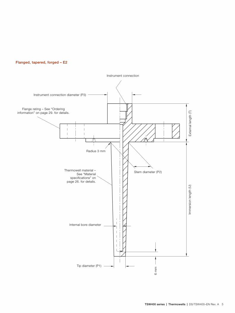
TSW400 series | Thermowells | DS/TSW400–EN Rev. A 5
Flanged, tapered, forged – E2
Flange rating – See “Ordering information” on page 29. for details.
Instrument connection
Internal bore diameter
Tip diameter (P1)
Instrument connection diameter (P3)
Thermowell material –See “Material
specifications” onpage 26. for details.
Imm
ersi
on le
ngth
(U)
Ext
erna
l len
gth
(T)
Radius 3 mm6
mm
Stem diameter (P2)
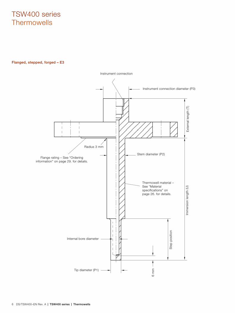
TSW400 seriesThermowells
6 DS/TSW400–EN Rev. A | TSW400 series | Thermowells
Flanged, stepped, forged – E3
Flange rating – See “Ordering information” on page 29. for details.
Instrument connection
Internal bore diameter
Tip diameter (P1)
Instrument connection diameter (P3)
Thermowell material – See “Material specifications” on page 26. for details.
Imm
ersi
on le
ngth
(U)
Ext
erna
l len
gth
(T)
Radius 3 mm
6 m
mStem diameter (P2)
Ste
p po
sitio
n

TSW400 series | Thermowells | DS/TSW400–EN Rev. A 7
Flanged, straight, full penetration weld – E4
Flange rating – See “Ordering information” on page 29. for details.
Instrument connection
Internal bore diameter
Tip diameter (P1)
Instrument connection diameter (P3)
Thermowell material – See “Material specifications” on page 26. for details.
Imm
ersi
on le
ngth
(U)
Ext
erna
l len
gth
(T)
Radius 3 mm
6 m
m

TSW400 seriesThermowells
8 DS/TSW400–EN Rev. A | TSW400 series | Thermowells
Flanged, tapered, full penetration weld – E5
Flange rating – See “Ordering information” on page 29. for details.
Instrument connection
Internal bore diameter
Tip diameter (P1)
Instrument connection diameter (P3)
Thermowell material –See “Material
specifications” onpage 26. for details.
Imm
ersi
on le
ngth
(U)
Ext
erna
l len
gth
(T)
Radius 3 mm6
mm
Stem diameter (P2)
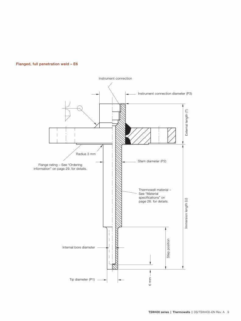
TSW400 series | Thermowells | DS/TSW400–EN Rev. A 9
Flanged, full penetration weld – E6
Flange rating – See “Ordering information” on page 29. for details.
Instrument connection
Internal bore diameter
Tip diameter (P1)
Instrument connection diameter (P3)
Thermowell material – See “Material specifications” on page 26. for details.
Imm
ersi
on le
ngth
(U)
Ext
erna
l len
gth
(T)
Radius 3 mm6
mm
Stem diameter (P2)
Ste
p po
sitio
n

TSW400 seriesThermowells
10 DS/TSW400–EN Rev. A | TSW400 series | Thermowells
Flanged, straight, fillet and groove weld – E7
Flange rating – See “Ordering information” on page 29. for details.
Instrument connection
Internal bore diameter
Tip diameter (P1)
Instrument connection diameter (P3)
Thermowell material – See “Material specifications” on page 26. for details.
Imm
ersi
on le
ngth
(U)
Ext
erna
l len
gth
(T)
Radius 3 mm6
mm

TSW400 series | Thermowells | DS/TSW400–EN Rev. A 11
Flanged, tapered, fillet and groove weld – E8
Flange rating – See “Ordering information” on page 29. for details.
Instrument connection
Internal bore diameter
Tip diameter (P1)
Instrument connection diameter (P3)
Thermowell material –See “Material
specifications” onpage 26. for details.
Imm
ersi
on le
ngth
(U)
Ext
erna
l len
gth
(T)
Radius 3 mm
6 m
m
Stem diameter (P2)
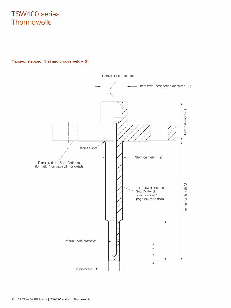
TSW400 seriesThermowells
12 DS/TSW400–EN Rev. A | TSW400 series | Thermowells
Flanged, stepped, fillet and groove weld – G1
Flange rating – See “Ordering information” on page 29. for details.
Instrument connection
Internal bore diameter
Tip diameter (P1)
Instrument connection diameter (P3)
Thermowell material – See “Material specifications” on page 26. for details.
Imm
ersi
on le
ngth
(U)
Ext
erna
l len
gth
(T)
Radius 3 mm
6 m
mStem diameter (P2)

TSW400 series | Thermowells | DS/TSW400–EN Rev. A 13
Flanged, tapered, fillet and groove weld with velocity collar – H1
Flange rating – See “Ordering information” on page 29. for details.
Instrument connection
Internal bore diameter
Tip diameter (P1)
Instrument connection diameter (P3)
Thermowell material –See “Material
specifications” onpage 26. for details.
Imm
ersi
on le
ngth
(U)
Ext
erna
l len
gth
(T)
Radius 3 mm
9 m
mStem diameter (P2)
Velo
city
col
lar
posi
tion
20 m
m
Velocity collar detail showing chamfers.Applies also to G2, G3, G4, G5, G6, G7, G8,
H1 and H2
30 °
Diameter(+0.02 –0.00 mm)

TSW400 seriesThermowells
14 DS/TSW400–EN Rev. A | TSW400 series | Thermowells
Van Stone, straight with cover flange – H3
Instrument connection
Internal bore diameter
Cover flange
Thermowell material –See “Material
specifications” onpage 26. for details.
Imm
ersi
on le
ngth
(U)
Ext
erna
l len
gth
(T)
Radius 4 mm
6 m
m
Stem diameter (P2)
Instrument connection diameter (P3)

TSW400 series | Thermowells | DS/TSW400–EN Rev. A 15
Van Stone, tapered with cover flange – H4
Tip diameter (P1)
Instrumentconnection
Internal bore diameter
Cover flange
Thermowell material –See “Material
specifications” onpage 26. for details.
Imm
ersi
on le
ngth
(U)
Ext
erna
l len
gth
(T)
Radius 4 mm
6 m
m
Stem diameter (P2)
Instrument connection diameter (P3)

TSW400 seriesThermowells
16 DS/TSW400–EN Rev. A | TSW400 series | Thermowells
Van Stone, stepped with cover flange – H5
Tip diameter (P1)
Instrument connection
Internal bore diameter
Cover flange
Thermowell material –See “Material
specifications” onpage 26. for details.
Imm
ersi
on le
ngth
(U)
Ext
erna
l len
gth
(T)
Radius 4 mm
6 m
m
Stem diameter (P2)
Instrument connection diameter (P3)
Ste
p po
sitio
n

TSW400 series | Thermowells | DS/TSW400–EN Rev. A 17
Weld-in, straight – J1
Instrument connection
Internal bore diameter
Thermowell material – See“Material specifications” on
page 26. for details. Imm
ersi
on le
ngth
(U)
Ext
erna
l len
gth
(T)
Radius 5 mm
6 m
m
Stem diameter (P2)
Instrument connection diameter (P3)

TSW400 seriesThermowells
18 DS/TSW400–EN Rev. A | TSW400 series | Thermowells
Weld-in, tapered – J2
Instrument connection
Internal bore diameter
Thermowell material – See“Material specifications” on
page 26. for details.
Imm
ersi
on le
ngth
(U)
Ext
erna
l len
gth
(T)
Radius 5 mm
6 m
m
Stem diameter (P2)
Instrument connection diameter (P3)
Tip diameter (P1)

TSW400 series | Thermowells | DS/TSW400–EN Rev. A 19
Weld-in, stepped – J3
Instrument connection
Internal bore diameter
Thermowell material – See“Material specifications” on
page 26. for details.
Imm
ersi
on le
ngth
(U)
Ext
erna
l len
gth
(T)
Radius 5 mm
6 m
m
Stem diameter (P2)
Instrument connection diameter (P3)
Tip diameter (P1)
Ste
p po
sitio
n

TSW400 seriesThermowells
20 DS/TSW400–EN Rev. A | TSW400 series | Thermowells
Threaded, straight – J4
Internal bore diameter
Thermowell material – See“Material specifications” on
page 26. for details.
Imm
ersi
on le
ngth
(U)
Ext
erna
l len
gth
(T)
6 m
m
Stem diameter (P2)
Male thread – See “Orderinginformation” on page 29. for details.
Female thread – See “Ordering information” on page 29. for details.
Hexagonal bar stock – See “Orderinginformation” on page 29. for details.
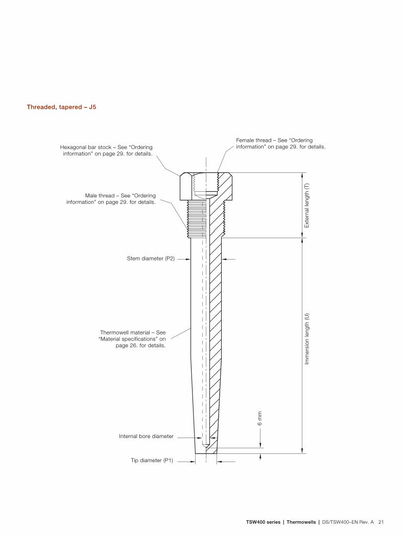
TSW400 series | Thermowells | DS/TSW400–EN Rev. A 21
Threaded, tapered – J5
Internal bore diameter
Thermowell material – See“Material specifications” on
page 26. for details.
Imm
ersi
on le
ngth
(U)
Ext
erna
l len
gth
(T)
6 m
mStem diameter (P2)
Male thread – See “Orderinginformation” on page 29. for details.
Female thread – See “Ordering information” on page 29. for details.Hexagonal bar stock – See “Ordering
information” on page 29. for details.
Tip diameter (P1)

TSW400 seriesThermowells
22 DS/TSW400–EN Rev. A | TSW400 series | Thermowells
Threaded, stepped – J6
Internal bore diameter
Thermowell material – See“Material specifications” on
page 26. for details.
Imm
ersi
on le
ngth
(U)
Ext
erna
l len
gth
(T)
6 m
m
Stem diameter (P2)
Male thread – See “Orderinginformation” on page 29. for details.
Female thread – See “Ordering information” on page 29. for details.Hexagonal bar stock – See “Ordering
information” on page 29. for details.
Tip diameter (P1)
Ste
p po
sitio
n

TSW400 series | Thermowells | DS/TSW400–EN Rev. A 23
Socket-weld, straight – J7
Internal bore diameter
Thermowell material – See“Material specifications” on
page 26. for details.
Imm
ersi
on le
ngth
(U)
Ext
erna
l len
gth
(T)
6 m
mStem diameter (P2)
Instrument connection
Socket diameter (P3)
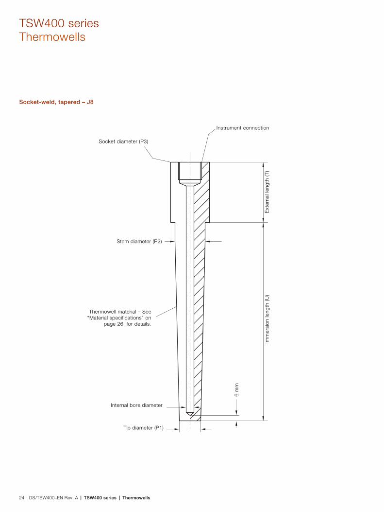
TSW400 seriesThermowells
24 DS/TSW400–EN Rev. A | TSW400 series | Thermowells
Socket-weld, tapered – J8
Internal bore diameter
Thermowell material – See“Material specifications” on
page 26. for details.
Imm
ersi
on le
ngth
(U)
Ext
erna
l len
gth
(T)
6 m
mStem diameter (P2)
Instrument connection
Socket diameter (P3)
Tip diameter (P1)
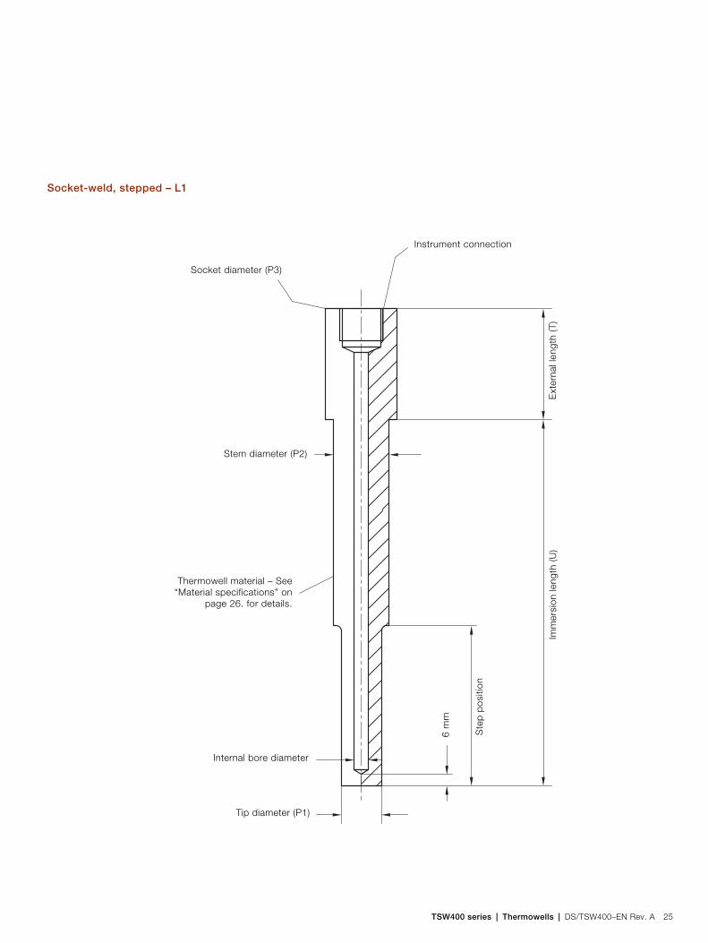
TSW400 series | Thermowells | DS/TSW400–EN Rev. A 25
Socket-weld, stepped – L1
Internal bore diameter
Thermowell material – See“Material specifications” on
page 26. for details.
Imm
ersi
on le
ngth
(U)
Ext
erna
l len
gth
(T)
6 m
mStem diameter (P2)
Instrument connection
Socket diameter (P3)
Tip diameter (P1)
Ste
p po
sitio
n

TSW400 seriesThermowells
26 DS/TSW400–EN Rev. A | TSW400 series | Thermowells
Material specifications
ABB can manufacture thermowells from almost any commercially available material. If the material required is not in the following list, contact ABB for advice.
— 316/ 316L stainless steelthe most commonly used material for thermowells combining excellent corrosion resistance with good strength and availability.
— 316Ti stainless steelan enhanced version of 316 – a small amount of titanium is added to help stabilize the material at temperatures over 800 °C (1472 °F).
— 321 stainless steeloffers similar properties to 316 and 316Ti but is more suitable for operation at higher temperatures.
— Hastelloy C-276a material favored for chloride atmospheres and processes. 300 series stainless steels are not recommended for use in high chloride and low oxygen environments.
— Inconel 600a high nickel alloy containing chromium – suitable for use at high temperatures and in both oxidizing and reducing atmospheres.
— Monel 400a high nickel alloy containing copper – highly resistant to corrosion in a wide variety of environments.
— Duplexa stainless steel designed specifically for use in salt water environments where it offers excellent corrosion resistance.
— Super duplexa variant of duplex steel that includes a small amount of copper – preferred over duplex for its enhanced high temperature properties.
Note. ABB are unable to specify a particular material for a process plant as this requires detailed process knowledge. However, ABB can discuss the implications of such choices on speed of delivery and cost. In addition, ABB welding engineers are available to advise on welding procedures for all materials.
Additional material specifications
Materials for use in 'sour' environments (environments containing high concentrations of hydrogen sulphide) normally demand material that complies with the NACE standard. ABB can comply fully with all these requirements.
Certain countries require that materials conform to particular requirements (for example, the NORSOK standard for materials for use in the North Sea).
ASME PTC 19.3 2010 TW stress calculationsThe only published international code for the evaluation of the stresses placed on thermowells in service. ABB engineers can perform a calculation to the ASME code on request. Certification is supplied when requested.
X-ray fluorescence PMIWhen absolute verification of the material supplied is required, ABB can perform an in-house X-ray fluorescence examination. This technique provides a quantitative analysis of the heavy elements in the chemical makeup of the material. The result can then be compared to the certification supplied by the producing mill.
Pressure testingTwo types of hydrostatic pressure test are offered by ABB:— External
tests the thermowell with pressure applied externally to the thermowell at 1.5 times the flange rating.
— Internaltests the thermowell internally for leaks.

TSW400 series | Thermowells | DS/TSW400–EN Rev. A 27
Weld integrity testingWeld integrity can be determined using:— dye penetrant
to detect external flaws in the weld
— X-rayto look deeply into the weld to detect internal flaws.
Only X-ray testing produces a permanent record of the weld integrity test in the form of a photograph (X-ray radiograph).
Bore concentricityThe concentricity of the thermowell bore is vitally important to the performance and safety of the thermowell. ABB uses specially designed, deep-hole drilling machines to produce an absolute confidence in bore concentricity. Additional ultrasonic testing of bore concentricity is standard practice in ABB factories. Additional verification is available in the form of two-axis radiographs that show the concentric bore.
Stainless steel surface treatmentStainless steels retain their stainless properties by virtue of a thin chromium oxide layer. This layer can be damaged by contaminants during manufacturing. The removal of these contaminants to enable the oxide layer to rebuild is vital for thermowell corrosion integrity. ABB standard practice is to thoroughly degrease each thermowell, both externally and internally, before delivery.
Upon request, ABB can also arrange for a separate 'pickling and passivation' procedure. This is done by first immersing the thermowell in a hot acid bath to remove any contaminants. The thermowell is then 'passivated' to rebuild the chromium oxide layer.
Other considerations
Thermowell insertion depthIdeally, the thermowell tip should be positioned in the center third of the pipe. In this position, the temperature measured is an accurate representation of the process temperature.
Additionally, the stem of the thermowell must be at least ten times longer than the tip diameter to minimize heat conduction errors. For example, a thermowell with a tip diameter of 16 mm (0.63 in.) must have a stem that is at least 160 mm (6.3 in.) long.
Narrow pipelines may prevent these two conditions from being met. In this case, it is acceptable to fit the thermowell into the pipe-line at angle or in a bend to accommodate the minimum recommended stem length.
However, if the pipeline is well lagged, a shorter thermowell may also provide a high degree of accuracy.

TSW400 seriesThermowells
28 DS/TSW400–EN Rev. A | TSW400 series | Thermowells
Speed of response
The factors that affect speed of response are many and varied.They include:
the thermal conductivity of the mediumthe flow rate of the mediumthe thermal conductivity of the thermowell materialthe thermowell dimensions
All these factors play a part in the eventual speed of response.
In general, thermowell-mounted instruments respond to changes in temperature faster than the process itself. If an increased rate of response is required, it can be achieved only by reducing the amount of material surrounding the measuring element therefore a stepped design thermowell must be used. However, a compromise must be made between the rate of response achievable and the strength required from the thermowell design.
Special designs
There may be occasions where a design of thermowell is required that cannot be developed from the available codes. ABB engineers can help with such a requirement. ABB has experience of delivering specialist designs within the Oil & Gas industry and can quote for such a need.
Some customers require approval before manufacture of designs; this can be achieved using ABB-engineered special designs.
Whatever the need – be it a special design or a problem with erosion or corrosion – ABB engineers can help.

TSW400 series | Thermowells | DS/TSW400–EN Rev. A 29
Ordering informationMain code Optional code
TSW 400 series thermowells TSW400 XX XX XX XXX X XX X XX XX X XXX XX XXX XX XX XX XX XX
Thermowell design See page 34
Flanged, straight, forged
Flanged, tapered, forged
Flanged, stepped, forged
Flanged, straight, full penetration weld
Flanged, tapered, full penetration weld
Flanged, stepped, full penetration weld
Flanged, straight, fillet & groove
Flanged, tapered, fillet & groove
Flanged, stepped, fillet & groove
Flanged, straight, forged with velocity collar
Flanged, tapered, forged with velocity collar
Flanged, stepped, forged with velocity collar
Flanged, straight, full penetration weld with velocity collar
Flanged, tapered, full penetration weld with velocity collar
Flanged, stepped, full penetration weld with velocity collar
Flanged, straight, fillet & groove with velocity collar
Flanged, tapered, fillet & groove with velocity collar
Flanged, stepped, fillet & groove with velocity collar
Van Stone, straight
Van Stone, tapered
Van Stone, stepped
Van Stone, straight with velocity collar
Van Stone, tapered with velocity collar
Van Stone, stepped with velocity collar
Weld-in, straight
Weld-in, tapered
Weld-in, stepped
Threaded, straight
Threaded, tapered
Threaded, stepped
Socket-weld, straight
Socket-weld, tapered
Socket-weld, stepped
DIN 43772 form 4
ABB form 4S
ABB form PW
DIN 43772 form 4F
ABB form 4FS
ABB form PF
ABB form PS
Other
E1
E2
E3
E4
E5
E6
E7
E8
G1
G2
G3
G4
G5
G6
G7
G8
H1
H2
H3
H4
H5
H6
H7
H8
J1
J2
J3
J4
J5
J6
J7
J8
L1
D1
D2
P1
D3
D4
P2
P3
Z9
Continued on next page …

TSW400 seriesThermowells
30 DS/TSW400–EN Rev. A | TSW400 series | Thermowells
See page 29 See page 34
Immersion length (U)
50 to 100 mm
101 to 150 mm
151 to 200 mm
201 to 250 mm
251 to 300 mm
301 to 350 mm
351 to 400 mm
401 to 450 mm
451 to 500 mm
501 to 550 mm
551 to 600 mm
601 to 650 mm
651 to 700 mm
701 to 750 mm
751 to 800 mm
801 to 850 mm
851 to 999 mm
A5
B1
B5
C1
C5
D1
D5
E1
E5
F1
F5
G1
G5
H1
H5
J1
J5
Thermowell material
Stainless steel 1.4404 / 316L
Stainless steel 1.4571 / 316Ti
Stainless steel 1.4541 / 321L
Hastelloy C-276 / 2.4819
Monel 400
Inconel 600
Duplex
Super duplex
Others
S1
S2
S6
N1
N4
N5
D1
D2
Z9
Continued on next page …
Main code Optional code
TSW 400 series thermowells TSW400 XX XX XX XXX X XX X XX XX X XXX XX XXX XX XX XX XX XX
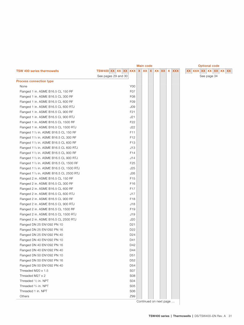
TSW400 series | Thermowells | DS/TSW400–EN Rev. A 31
See pages 29 and 30 See page 34
Process connection type
None
Flanged 1 in. ASME B16.5 CL 150 RF
Flanged 1 in. ASME B16.5 CL 300 RF
Flanged 1 in. ASME B16.5 CL 600 RF
Flanged 1 in. ASME B16.5 CL 600 RTJ
Flanged 1 in. ASME B16.5 CL 900 RF
Flanged 1 in. ASME B16.5 CL 900 RTJ
Flanged 1 in. ASME B16.5 CL 1500 RF
Flanged 1 in. ASME B16.5 CL 1500 RTJ
Flanged 11/2 in. ASME B16.5 CL 150 RF
Flanged 11/2 in. ASME B16.5 CL 300 RF
Flanged 11/2 in. ASME B16.5 CL 600 RF
Flanged 11/2 in. ASME B16.5 CL 600 RTJ
Flanged 11/2 in. ASME B16.5 CL 900 RF
Flanged 11/2 in. ASME B16.5 CL 900 RTJ
Flanged 11/2 in. ASME B16.5 CL 1500 RF
Flanged 11/2 in. ASME B16.5 CL 1500 RTJ
Flanged 11/2 in. ASME B16.5 CL 2500 RTJ
Flanged 2 in. ASME B16.5 CL 150 RF
Flanged 2 in. ASME B16.5 CL 300 RF
Flanged 2 in. ASME B16.5 CL 600 RF
Flanged 2 in. ASME B16.5 CL 600 RTJ
Flanged 2 in. ASME B16.5 CL 900 RF
Flanged 2 in. ASME B16.5 CL 900 RTJ
Flanged 2 in. ASME B16.5 CL 1500 RF
Flanged 2 in. ASME B16.5 CL 1500 RTJ
Flanged 2 in. ASME B16.5 CL 2500 RTJ
Flanged DN 25 EN1092 PN 10
Flanged DN 25 EN1092 PN 16
Flanged DN 25 EN1092 PN 40
Flanged DN 40 EN1092 PN 10
Flanged DN 40 EN1092 PN 16
Flanged DN 40 EN1092 PN 40
Flanged DN 50 EN1092 PN 10
Flanged DN 50 EN1092 PN 16
Flanged DN 50 EN1092 PN 40
Threaded M20 x 1.5
Threaded M27 x 2
Threaded 1/2 in. NPT
Threaded 3/4 in. NPT
Threaded 1 in. NPT
Others
Y00
F07
F08
F09
J09
F21
J21
F22
J22
F11
F12
F13
J13
F14
J14
F25
J25
J26
F15
F16
F17
J17
F18
J18
F19
J19
J20
D21
D22
D24
D41
D42
D44
D51
D52
D54
S07
S08
S04
S05
S06
Z99
Continued on next page …
Main code Optional code
TSW 400 series thermowells TSW400 XX XX XX XXX X XX X XX XX X XXX XX XXX XX XX XX XX XX

TSW400 seriesThermowells
32 DS/TSW400–EN Rev. A | TSW400 series | Thermowells
See pages 29 to 31 See page 34
Instrument connection1/2 in. NPT (standard)
M20 x 1.51/2 in. BSP
A
D
E
External length (T)
0 mm to...
90 mm
00
90
Instrument connection diameter (P3)
32 mm
35 mm
40 mm
Others
A
B
C
Z
Stem diameter (P2)
16 mm to...
38 mm
16
38
Continued on next page …
Main code Optional code
TSW 400 series thermowells TSW400 XX XX XX XXX X XX X XX XX X XXX XX XXX XX XX XX XX XX

TSW400 series | Thermowells | DS/TSW400–EN Rev. A 33
See pages 29 to 32 See page 34
Tip diameter (P1)
12 mm
12.5 mm
13 mm
13.5 mm
14 mm
14.5 mm
15 mm
15.5 mm
16 mm
16.5 mm
17 mm
17.5 mm
18 mm
18.5 mm
19 mm
19.5 mm
20 mm
20.5 mm
21 mm
21.5 mm
22 mm
22.5 mm
23 mm
23.5 mm
24 mm
24.5 mm
25 mm
25.5 mm
26 mm
26.5 mm
27 mm
27.5 mm
28 mm
28.5 mm
29 mm
29.5 mm
30 mm
A1
A2
A3
A4
A5
A6
A7
A8
A9
B0
B1
B2
B3
B4
B5
B6
B7
B8
B9
C0
C1
C2
C3
C4
C5
C6
C7
C8
C9
D0
D1
D2
D3
D4
D5
D6
D7
Continued on next page …
Main code Optional code
TSW 400 series thermowells TSW400 XX XX XX XXX X XX X XX XX X XXX XX XXX XX XX XX XX XX

TSW400 seriesThermowells
34 DS/TSW400–EN Rev. A | TSW400 series | Thermowells
See pages 29 to 33
Internal bore
3.5 mm
6.5 mm
7.0 mm
8.0 mm
9.0 mm
9.5 mm
10 mm
13 mm
A
B
C
D
E
F
G
H
Step position
None
50 mm to...
150 mm
000
050
150
Usage certifications
3.1 cert materials traceability report
Certificate of conformity
Dimensional report
NACE material certification
C2
C4
C6
CN
Other usage certifications
Russia, Metrological and GOST-R certificate
NORSOK
CG1
CN2
Plug and chain
Plug and chain (stainless steel) H8
Documentation language
German
Spanish
French
English
M1
M3
M4
M5
Non-destructive tests
X-ray fluorescence PMI
Dye penetration of weld integrity
Ultrasonic tip concentricity
Helium leak testing
Pressure test external (water)
Pressure test internal (water)
Radiograph process connection
Radiograph tip concentricity
N1
N2
N3
N4
N5
N6
N7
N8
Continued on next page …
Main code Optional code
TSW 400 series thermowells TSW400 XX XX XX XXX X XX X XX XX X XXX XX XXX XX XX XX XX XX

TSW400 series | Thermowells | DS/TSW400–EN Rev. A 35
See pages 29 to 34
See page 34
Reporting options
Weld location report
Weld qualification report
Wake frequency calculation
Hardness report
ND
NE
NG
NH
Operations options
De-pip, to produce a flat bore end
Non standard flange to stem weld radius
Non Standard tip thickness
Non Standard tip profile (chamfered)
Non Standard tip profile (domed)
Pickling and passivation
Material source limitations apply
European only materials
SB
SW
ST
SH
SR
SC
SD
SE
Added characteristics
Actual immersion length (mm)
Velocity collar diameter (mm)
Velocity collar position (mm)
Tag number
Material source limitations
Non standard flange to stem weld radius
Non standard tip thickness
Main code Optional code
TSW 400 series thermowells TSW400 XX XX XX XXX X XX X XX XX X XXX XX XXX XX XX XX XX XX
Contact us
DS
/TS
W40
0–EN
Rev
. A03
.201
5ABB LimitedProcess AutomationSalterbeck Trading EstateWorkington, CumbriaCA14 5DSUKTel: +44 (0)1946 830 611Fax: +44 (0)1946 832 661
ABB Automation Products GmbHProcess AutomationSchillerstr. 7232425 MindenDeutschlandTel: +49 551 905 534Fax: +49 551 905 555
www.abb.com
NoteWe reserve the right to make technical changes or modify the contents of this document without prior notice. With regard to purchase orders, the agreed particulars shall prevail. ABB does not accept any responsibility whatsoever for potential errors or possible lack of information in this document.
We reserve all rights in this document and in the subject matter and illustrations contained therein. Any reproduction, disclosure to third parties or utilization of its contents in whole or in parts – is forbidden without prior written consent of ABB.
Copyright© 2015 ABBAll rights reserved
3KXT181401R1001
Sales Service
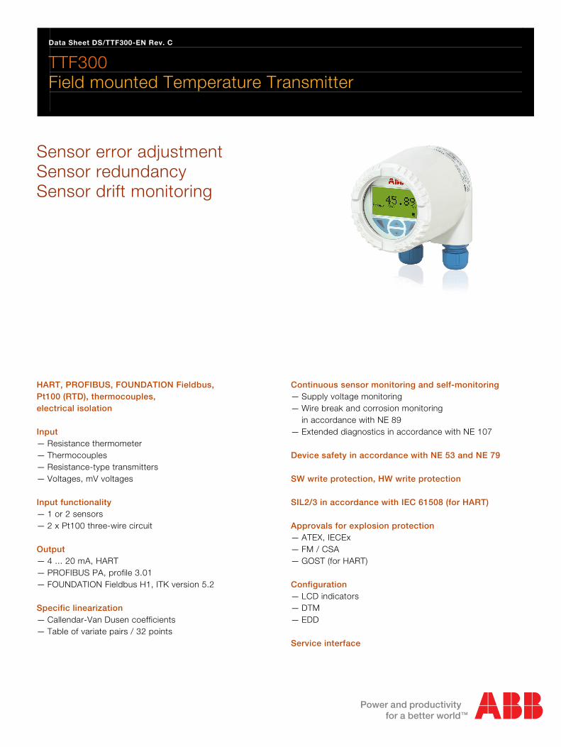
Data Sheet DS/TTF300-EN Rev. C
TTF300 Field mounted Temperature Transmitter
Sensor error adjustment Sensor redundancy Sensor drift monitoring
HART, PROFIBUS, FOUNDATION Fieldbus, Pt100 (RTD), thermocouples, electrical isolation Input — Resistance thermometer — Thermocouples — Resistance-type transmitters — Voltages, mV voltages Input functionality — 1 or 2 sensors — 2 x Pt100 three-wire circuit Output — 4 ... 20 mA, HART — PROFIBUS PA, profile 3.01 — FOUNDATION Fieldbus H1, ITK version 5.2 Specific linearization — Callendar-Van Dusen coefficients — Table of variate pairs / 32 points
Continuous sensor monitoring and self-monitoring — Supply voltage monitoring — Wire break and corrosion monitoring
in accordance with NE 89 — Extended diagnostics in accordance with NE 107 Device safety in accordance with NE 53 and NE 79 SW write protection, HW write protection SIL2/3 in accordance with IEC 61508 (for HART) Approvals for explosion protection — ATEX, IECEx — FM / CSA — GOST (for HART) Configuration — LCD indicators — DTM — EDD Service interface
Contents
Field mounted Temperature Transmitter TTF300 DS/TTF300-EN HART, PROFIBUS, FOUNDATION Fieldbus, Pt100 (RTD), thermocouples, electrical isolation
2
Contents 1 Specifications ......................................................................................................................................................4
1.1 Input................................................................................................................................................................4 1.2 Output.............................................................................................................................................................5 1.3 Power supply (polarity safe) ...........................................................................................................................5
2 General information ............................................................................................................................................6 2.1 Ambient conditions .........................................................................................................................................6 2.2 SIL functional safety .......................................................................................................................................6 2.3 ElectroMagnetic Compatibility........................................................................................................................6 2.4 Interference immunity.....................................................................................................................................6 2.5 Mechanical design..........................................................................................................................................6 2.6 Measuring accuracy .......................................................................................................................................7 2.7 Operating influences ......................................................................................................................................8
3 Communication ...................................................................................................................................................9 3.1 Configuration parameters...............................................................................................................................9 3.2 HART..............................................................................................................................................................9 3.3 PROFIBUS PA .............................................................................................................................................10 3.4 FOUNDATION Fieldbus...............................................................................................................................10
4 Electrical connections ......................................................................................................................................11 5 Dimensions ........................................................................................................................................................12 6 Ordering information.........................................................................................................................................13
6.1 Documentation available for ordering ..........................................................................................................15 7 Ex relevant specifications ................................................................................................................................15
7.1 TTF300-E1X, intrinsic safety ATEX .............................................................................................................15 7.2 TTF300-H1X, intrinsic safety IECEx ............................................................................................................15 7.3 Safety specifications for Intrinsic Safety ATEX / IECEx...............................................................................15 7.4 TTF300-E5X, non-sparking + dust explosion protection ATEX ...................................................................16 7.5 TTF300-D1X, dust explosion protection ATEX ............................................................................................16 7.6 TTF300-D2X, dust explosion protection + intrinsic safety ATEX .................................................................16 7.7 TTF300-E3X, flameproof enclosure ATEX...................................................................................................16 7.8 TTF300-E4X, flameproof enclosure + intrinsic safety ATEX ......................................................................16 7.9 TTF300-L1X, intrinsically safe FM ...............................................................................................................16 7.10 TTF300-L2X, non-incendive FM ..................................................................................................................16 7.11 TTF300-L3X, explosion proof FM ................................................................................................................16 7.12 TTF300-L7X, explosion proof + intrinsically safe FM...................................................................................16 7.13 TTF300-R1X, intrinsically safe CSA.............................................................................................................16 7.14 TTF300-R2X, non-incendive CSA................................................................................................................16 7.15 TTF300-R3X, explosion proof CSA..............................................................................................................16 7.16 TTF300-R7X, explosion proof + intrinsically safe CSA................................................................................16
8 Type B LCD ........................................................................................................................................................17
Field mounted Temperature Transmitter TTF300 DS/TTF300-EN HART, PROFIBUS, FOUNDATION Fieldbus, Pt100 (RTD), thermocouples, electrical isolation
3
8.1 Features .......................................................................................................................................................17 8.2 Specifications ...............................................................................................................................................17 8.3 Configuration function ..................................................................................................................................17 8.4 Ex relevant specifications.............................................................................................................................17
9 Order form configuration..................................................................................................................................19 9.1 HART device design: Data relating to customer-specific configuration .......................................................19 9.2 PROFIBUS PA / FOUNDATION Fieldbus device design ............................................................................20
Data Sheet Field mounted Temperature Transmitter

Field mounted Temperature Transmitter TTF300 DS/TTF300-EN HART, PROFIBUS, FOUNDATION Fieldbus, Pt100 (RTD), thermocouples, electrical isolation
4
1 Specifications Change from one to two columns
1.1 Input
1.1.1 Resistance thermometers / Resistors
Resistance thermometers Pt100 in accordance with IEC 60751, JIS C1604-89, MIL-T-24388, Ni in accordance with DIN 43760, Cu
Resistance measurement 0 … 500 Ω 0 … 5000 Ω
Sensor connection type Two-, three-, four-wire circuit
Connecting cable Maximum sensor line resistance (RW) for each line 50 Ω according to NE 89 (January 2009) Three-wire circuit: symmetrical sensor line resistances Two-wire circuit: compensation up to 100 Ω total line resistance
Measurement current < 300 µA
Sensor short circuit < 5 Ω (for resistance thermometer)
Sensor wire break Measuring range: 0 ... 500 Ω > 0.6 ... 10 kΩMeasuring range: 0 ... 5 kΩ > 5.3 ... 10 kΩ
Corrosion detection in accordance with NE 89 Three-wire resistance measurement > 50 Ω Four-wire resistance measurement > 50 Ω
Sensor error signaling Resistance thermometers: Short circuit and wire break Linear resistance measurement: Wire break
1.1.2 Thermocouples / Voltages
Types B, E, J, K, N, R, S, T in accordance with IEC 60584 U, L in accordance with DIN 43710 C, D in accordance with ASTM E-988
Voltages -125 ... 125 mV -125 ... 1100 mV
Connecting cable Maximum sensor line resistance (RW) for each line: 1.5 kΩ, total: 3 kΩ
Sensor wire-break monitoring in accordance with NE 89 Pulsed with 1 µA outside measurement interval Thermocouple measurement 5.3 ... 10 kΩ Voltage measurement 5.3 ... 10 kΩ
Input resistance > 10 MΩ
Internal reference point Pt1000, IEC 60751 Cl. B (no additional jumpers necessary)
Sensor error signaling Thermocouple: Wire break Linear voltage measurement: Wire break
1.1.3 Functionality
Freestyle characteristics and 32-point sampling table Resistance measurement up to maximum 5 kΩ Voltages up to maximum 1.1 V
Sensor error adjustment Via Callendar van Dusen coefficients Via table of 32 sampling points Via single-point adjustment (offset adjustment) Via two-point adjustment
Input functionality 1 sensor 2 sensors: mean measurement, differential measurement, sensor redundancy, sensor drift monitoring

Field mounted Temperature Transmitter TTF300 DS/TTF300-EN HART, PROFIBUS, FOUNDATION Fieldbus, Pt100 (RTD), thermocouples, electrical isolation
5
1.2 Output
1.2.1 HART output
Transmission characteristics Temperature linear Resistance linear Voltage linear
Output signal Configurable 4 ... 20 mA (standard) Configurable 20 ... 4 mA (dynamic range: 3.8 ... 20.5 mA in accordance with NE 43)
Simulation mode 3.5 ... 23.6 mA
Induced current consumption < 3.5 mA
Maximum output current 23.6 mA
Configurable error current signal Override 22 mA (20.0 … 23.6 mA) Underdrive 3.6 mA (3.5 … 4.0 mA)
1.2.2 PROFIBUS PA output
Output signal PROFIBUS – MBP (IEC 61158-2) baud rate 31.25 kbit/s PA profile 3.01 FISCO-compliant (IEC 60079-27) IDENT_ NUMBER: 0x3470 [0x9700]
Error current signal FDE (Fault Disconnection Electronic)
Block structure Physical block transducer block 1 – temperature transducer block 2 – HMI (LCD) transducer block 3 – extended diagnostics analog input 1 – primary value (calculated value*) analog input 2 – SECONDARY VALUE_1 (sensor 1) analog input 3 – SECONDARY VALUE_2 (sensor 2) analog input 4 – SECONDARY VALUE_3 (reference point temp.) analog output – optional HMI display (transducer block 2) discrete input 1 – extended diagnostics 1 (transducer block 3) discrete input 2 – extended diagnostics 2 (transducer block 3) * Sensor 1, sensor 2, or difference, or mean
1.2.3 FOUNDATION Fieldbus output
Output signal FOUNDATION Fieldbus H1 (IEC 611582-2) Baud rate 31.25 kbit/s, ITK 5.2 FISCO-compliant (IEC 60079-27) Device ID: 0003200125
Error current signal FDE (Fault Disconnection Electronic)
Block structure 1)
Resource block Transducer block 1 – temperature Transducer block 2 – HMI (LCD) Transducer block 3 – extended diagnostics Analog input 1 – PRIMARY_VALUE_1 (sensor 1) Analog input 2 – PRIMARY_VALUE_2 (sensor 2) Analog input 3 – PRIMARY_VALUE_3 (calculated value*) Analog input 4 – SECONDARY_VALUE (reference point temp.) Analog output – optional HMI display (transducer block 2) Discrete input 1 – extended diagnostics 1 (transducer block 3) Discrete input 2 – extended diagnostics 2 (transducer block 3) PID – PID controller * Sensor 1, sensor 2, or difference, or mean
LAS (Link Active Scheduler) link master functionality
1) For the block description, block index, execution times, and block class, refer to the interface description.
1.3 Power supply (polarity safe) Speisespannung
Two-wire technology; supply power lines = signal lines
1.3.1 HART supply power
Supply voltage Non-ignition-proof application: US = 11 ... 42 V DC Ignition-proof applications: US = 11 ... 30 V DC
Max. permissible residual ripple for supply voltage During communication in accordance with HART FSK "Physical Layer" specification, version 8.1 (August 1999) Section 8.1
Undervoltage detection UTerminal-Mu < 10 V results in Ia = 3.6 mA
Maximum load RLoad = (supply voltage – 11 V) / 0.022 A
A0000111 16 4230
A
[V DC][V DC]
[ ][ ]
250
500
750
860
1000
1250
1400
B
C
Fig. 1: Maximum load depending on supply voltage
A TTF300 B TTF300 In ia hazardous area design C HART communication resistor
Maximum power consumption P = Us x 0.022 A e.g., Us = 24 V Pmax = 0.528 W
1.3.2 PROFIBUS / FOUNDATION Fieldbus supply power
Supply voltage Non-ignition-proof application: US = 9 ... 32 V DC Ignition-proof applications: US = 9 ... 17.5 V DC (FISCO) US = 9 ... 24 V DC (Fieldbus Entity model I.S.) Current consumption ≤ 12 mA
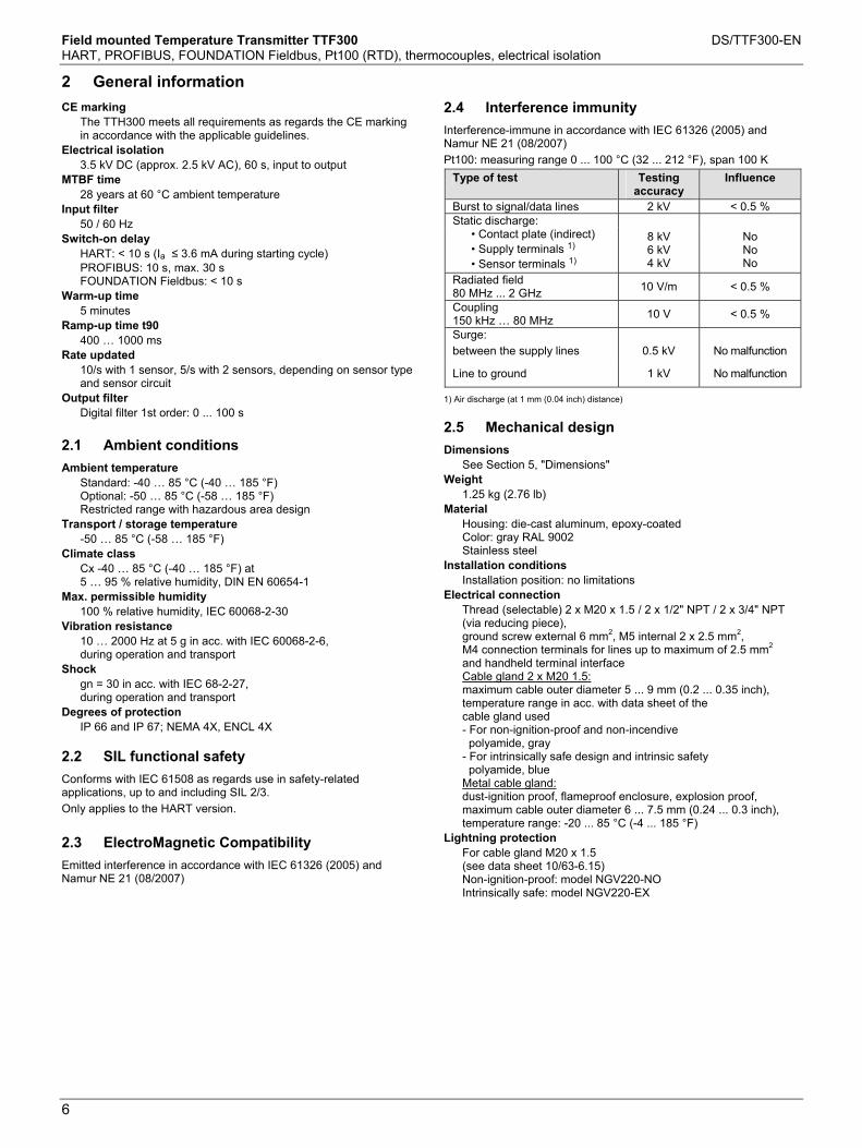
Field mounted Temperature Transmitter TTF300 DS/TTF300-EN HART, PROFIBUS, FOUNDATION Fieldbus, Pt100 (RTD), thermocouples, electrical isolation
6
Change from one to two columns
2 General information Change from one to two columns
CE marking The TTH300 meets all requirements as regards the CE marking in accordance with the applicable guidelines.
Electrical isolation 3.5 kV DC (approx. 2.5 kV AC), 60 s, input to output
MTBF time 28 years at 60 °C ambient temperature
Input filter 50 / 60 Hz
Switch-on delay HART: < 10 s (Ia ≤ 3.6 mA during starting cycle) PROFIBUS: 10 s, max. 30 s FOUNDATION Fieldbus: < 10 s
Warm-up time 5 minutes
Ramp-up time t90 400 … 1000 ms
Rate updated 10/s with 1 sensor, 5/s with 2 sensors, depending on sensor type and sensor circuit
Output filter Digital filter 1st order: 0 ... 100 s
2.1 Ambient conditions
Ambient temperature Standard: -40 … 85 °C (-40 … 185 °F) Optional: -50 … 85 °C (-58 … 185 °F) Restricted range with hazardous area design
Transport / storage temperature -50 … 85 °C (-58 … 185 °F)
Climate class Cx -40 … 85 °C (-40 … 185 °F) at 5 … 95 % relative humidity, DIN EN 60654-1
Max. permissible humidity 100 % relative humidity, IEC 60068-2-30
Vibration resistance 10 … 2000 Hz at 5 g in acc. with IEC 60068-2-6, during operation and transport
Shock gn = 30 in acc. with IEC 68-2-27, during operation and transport
Degrees of protection IP 66 and IP 67; NEMA 4X, ENCL 4X
2.2 SIL functional safety
Conforms with IEC 61508 as regards use in safety-related applications, up to and including SIL 2/3.
Only applies to the HART version.
2.3 ElectroMagnetic Compatibility
Emitted interference in accordance with IEC 61326 (2005) and Namur NE 21 (08/2007)
2.4 Interference immunity
Interference-immune in accordance with IEC 61326 (2005) and Namur NE 21 (08/2007)
Pt100: measuring range 0 ... 100 °C (32 ... 212 °F), span 100 K
Type of test Testing accuracy
Influence
Burst to signal/data lines 2 kV < 0.5 % Static discharge:
• Contact plate (indirect) • Supply terminals 1) • Sensor terminals 1)
8 kV 6 kV 4 kV
No No No
Radiated field 80 MHz ... 2 GHz
10 V/m < 0.5 %
Coupling 150 kHz … 80 MHz
10 V < 0.5 %
Surge: between the supply lines 0.5 kV No malfunction
Line to ground 1 kV No malfunction
1) Air discharge (at 1 mm (0.04 inch) distance)
2.5 Mechanical design
Dimensions See Section 5, "Dimensions"
Weight 1.25 kg (2.76 lb)
Material Housing: die-cast aluminum, epoxy-coated Color: gray RAL 9002 Stainless steel
Installation conditions Installation position: no limitations
Electrical connection Thread (selectable) 2 x M20 x 1.5 / 2 x 1/2" NPT / 2 x 3/4" NPT (via reducing piece), ground screw external 6 mm2, M5 internal 2 x 2.5 mm2, M4 connection terminals for lines up to maximum of 2.5 mm2
and handheld terminal interface Cable gland 2 x M20 1.5: maximum cable outer diameter 5 ... 9 mm (0.2 ... 0.35 inch), temperature range in acc. with data sheet of the cable gland used - For non-ignition-proof and non-incendive polyamide, gray - For intrinsically safe design and intrinsic safety polyamide, blue Metal cable gland: dust-ignition proof, flameproof enclosure, explosion proof, maximum cable outer diameter 6 ... 7.5 mm (0.24 ... 0.3 inch), temperature range: -20 ... 85 °C (-4 ... 185 °F)
Lightning protection For cable gland M20 x 1.5 (see data sheet 10/63-6.15) Non-ignition-proof: model NGV220-NO Intrinsically safe: model NGV220-EX

Field mounted Temperature Transmitter TTF300 DS/TTF300-EN HART, PROFIBUS, FOUNDATION Fieldbus, Pt100 (RTD), thermocouples, electrical isolation
7
Change from one to two columns
2.6 Measuring accuracy
Includes linearity deviation. reproducibility / hysteresis at 23 °C (73.4 °F) ± 5 K and 20 V supply voltage
Information on measuring accuracy corresponds to 3 (Gaussian distribution)
Input element
Standard Sensor Measuring range limits Minimum span
Digital measuring accuracy (24-bit A/D converter)
D/A measuring accuracy 1)
(16-bit DA)
Resistance thermometer / Resistor
DIN IEC 60 751 Pt10 Pt50 Pt100 Pt200 Pt500 Pt1000
(a=0.003850) (a=0.003850) (a=0.003850) 2) (a=0.003850) (a=0.003850) (a=0.003850)
-200 ... 850 °C -200 ... 850 °C -200 ... 850 °C-200 ... 850 °C -200 ... 850 °C -200 ... 850 °C
(-328 ... 1562 °F) (-328 ... 1562 °F) (-328 ... 1562 °F) (-328 ... 1562 °F) (-328 ... 1562 °F) (-328 ... 1562 °F)
10 °C 10 °C 10 °C 10 °C 10 °C 10 °C
(18 °F) (18 °F) (18 °F) (18 °F) (18 °F) (18 °F)
± 0.80 °C ± 0.16 °C ± 0.08 °C ± 0.24 °C ± 0.16 °C ± 0.08 °C
(± 1.44 °F) (± 0.29 °F) (± 0.14 °F) (± 0.43 °F) (± 0.29 °F) (± 0.14 °F)
± 0.05 % ± 0.05 % ± 0.05 % ± 0.05 % ± 0.05 % ± 0.05 %
JIS C1604-89 Pt10 Pt50 Pt100
(a=0.003916) (a=0.003916) (a=0.003916)
-200 ... 645 °C -200 ... 645 °C -200 ... 645 °C
(-328 ... 1193 °F) (-328 ... 1193 °F) (-328 ... 1193 °F)
10 °C 10 °C 10 °C
(18 °F) (18 °F) (18 °F)
± 0.80 °C ± 0.16 °C ± 0.08 °C
(± 1.44 °F) (± 0.29 °F) (± 0.14 °F)
± 0.05 % ± 0.05 % ± 0.05 %
MIL-T-24388 Pt10 Pt50 Pt100 Pt200 Pt500 Pt1000
(a=0,003920) (a=0,003920) (a=0,003920) (a=0,003920) (a=0,003920) (a=0,003920)
-200 ... 850 °C -200 ... 850 °C -200 ... 850 °C -200 ... 850 °C -200 ... 850 °C -200 ... 850 °C
(-328 ... 1562 °F) (-328 ... 1562 °F) (-328 ... 1562 °F) (-328 ... 1562 °F) (-328 ... 1562 °F) (-328 ... 1562 °F)
10 °C 10 °C 10 °C 10 °C 10 °C 10 °C
(18 °F) (18 °F) (18 °F) (18 °F) (18 °F) (18 °F)
± 0,80 °C ± 0,16 °C ± 0,08 °C ± 0,24 °C ± 0,16 °C ± 0,08 °C
(± 1,44 °F) (± 0,29 °F) (± 0,14 °F) (± 0,43 °F) (± 0,29 °F) (± 0,14 °F)
± 0,05 % ± 0,05 % ± 0,05 % ± 0,05 % ± 0,05 % ± 0,05 %
DIN 43760 Ni50 Ni100 Ni120 Ni1000
(a=0.006180) (a=0.006180) (a=0.006180) (a=0.006180)
-60 ... 250 °C -60 ... 250 °C -60 ... 250 °C -60 ... 250 °C
(-76 ... 482 °F) (-76 ... 482 °F) (-76 ... 482 °F) (-76 ... 482 °F)
10 °C 10 °C 10 °C 10 °C
(18 °F) (18 °F) (18 °F) (18 °F)
± 0.16 °C ± 0.08 °C ± 0.08 °C ± 0.08 °C
(± 0.29 °F) (± 0.14 °F) (± 0.14 °F) (± 0.14 °F)
± 0.05 % ± 0.05 % ± 0.05 % ± 0.05 %
Cu10 Cu100
(a=0.004270) (a=0.004270)
-50 ... 200 °C -50 ... 200 °C
(-58 ... 392 °F) (-58 ... 392 °F)
10 °C 10 °C
(18 °F) (18 °F)
± 0.80 °C ± 0.08 °C
(± 1.44 °F) (± 0.14 °F)
± 0.05 % ± 0.05 %
Resistance measurement Resistance measurement
0 ... 500 Ω 0 ... 5000 Ω
4 Ω 40 Ω
± 32 mΩ ± 320 mΩ
± 0.05 % ± 0.05 %
Thermocouples 3) / voltages
IEC 60584 Type K Type J Type N Type T Type E Type R Type S Type B
(Ni10Cr-Ni5) (Fe-Cu45Ni) (Ni14CrSi-NiSi) (Cu-Cu45Ni) (Ni10Cr-Cu45Ni) (Pt13Rh-Pt) (Pt10Rh-Pt) (Pt30Rh-Pt6Rh)
-270 ... 1372 °C -210 ... 1200 °C -270 ... 1300 °C -270 ... 400 °C -270 ... 1000 °C -50 ... 1768 °C -50 ... 1768 °C -0 ... 1820 °C
(-454 ... 2502 °F) (-346 ... 2192 °F) (-454 ... 2372 °F) (-454 ... 752 °F) (-454 ... 1832 °F) (-58 ... 3215 °F) (-58 ... 3215 °F) (32 ... 3308 °F)
50 °C 50 °C 50 °C 50 °C 50 °C 100 °C100 °C100 °C
(90 °F) (90 °F) (90 °F) (90 °F) (90 °F) (180 °F)(180 °F)(180 °F)
± 0.35 °C ± 0.35 °C ± 0.35 °C ± 0.35 °C ± 0.35 °C ± 0.95 °C ± 0.95 °C ± 0.95 °C
(± 0.63 °F) (± 0.63 °F) (± 0.63 °F) (± 0.63 °F) (± 0.63 °F) (± 1.71 °F) (± 1.71 °F) (± 1.71 °F)
± 0.05 % ± 0.05 % ± 0.05 % ± 0.05 % ± 0.05 % ± 0.05 % ± 0.05 % ± 0.05 %
DIN 43710 Type L Type U
(Fe-CuNi) (Cu-CuNi)
-200 ... 900 °C -200 ... 600 °C
(-328 ... 1652 °F) (-328 ... 1112 °F)
50 °C 50 °C
(90 °F) (90 °F)
± 0.35 °C ± 0.35 °C
(± 0.63 °F) (± 0.63 °F)
± 0.05 % ± 0.05 %
ASTM E 988 Type C
Type D -0 ... 2315 °C -0 ... 2315 °C
(32 ... 4200 °F) (32 ... 4200 °F)
100 °C100 °C
(180 °F)(180 °F)
± 1.35 °C ± 1.35 °C
(± 2.43 °F) (± 2.43 °F)
± 0.05 % ± 0.05 %
Voltage measurement Voltage measurement
-125 ... 125 mV -125 ... 1100 mV
2 mV 20 mV
± 12 µV ± 120 µV
± 0.05 % ± 0.05 %
Long-term drift ± 0.05 °C (± 0.09 °F) or ± 0.05 % 1) per year. the larger value applies. 1) Percentages refer to the configured measuring span 2) Standard model 3) Include the internal reference point error for digital measuring accuracy: Pt1000. DIN IEC 60751 Cl. B 4) Without reference junction error

Field mounted Temperature Transmitter TTF300 DS/TTF300-EN HART, PROFIBUS, FOUNDATION Fieldbus, Pt100 (RTD), thermocouples, electrical isolation
8
2.7 Operating influences
The percentages refer to the configured measuring span.
Influence of supply voltage / load: within the specified limits for the voltage / load, the total influence is less than 0.001 % per volt
Normal-mode rejection: > 65 dB at 50 / 60 Hz,
Common-mode rejection: > 120 dB at 50 / 60 Hz
Influence of ambient temperature: based on 23 °C (73.4 °F) for an ambient temperature range of -40 ... 85 °C (-40 ... 185 °F) 4)
Sensor Influence of ambient temperature
per 1 °C (1.8 °F) deviation from 23 °C (73.4 °F) for digital measurement
Influence of ambient temperature 1) 2)
per 1 °C (1.8 °F) deviation from 23 °C (73.4 °F) for D/A converter
Resistance thermometer for two-, three-, four-wire circuits
Pt10
Pt50
Pt100
Pt200
Pt500
Pt1000
IEC, JIS, MIL
IEC, JIS, MIL
IEC, JIS, MIL
IEC, MIL
IEC, MIL
IEC, MIL
± 0,04 °C (± 0,072 °F)
± 0,008 °C (± 0,014 °F)
± 0,004 °C (± 0,007 °F)
± 0,02 °C (± 0,036 °F)
± 0,008 °C (± 0,014 °F)
± 0,004 °C (± 0,007 °F)
± 0,003 %
± 0,003 %
± 0,003 %
± 0,003 %
± 0,003 %
± 0,003 %
Ni50
Ni100
Ni120
Ni1000
DIN 43760
DIN 43760
DIN 43760
DIN 43760
± 0,008 °C (± 0,014 °F)
± 0,004 °C (± 0,007 °F)
± 0,003 °C (± 0,005 °F)
± 0,004 °C (± 0,007 °F)
± 0,003 %
± 0,003 %
± 0,003 %
± 0,003 %
Cu10
Cu100
± 0,04 °C (± 0,072 °F)
± 0,004 °C (± 0,007 °F)
± 0,003 %
± 0,003 %
Resistance measurement 0 ... 500 Ω 0 ... 5000 Ω
± 0,002 Ω ± 0,02 Ω
± 0,003 % ± 0,003 %
Thermocouple, for all defined types
± [(0,001 % x (ME[mV] / MS[mv]) + (100 % x (0,009 °C / MS [°C])] 3) ± 0,003 %
Voltage measurement -125 ... 125 mV -125 ... 1100 mV
± 1,5 µV ± 15 µV
± 0,003 % ± 0,003 %
1) Percentages refer to the configured measuring span of the analog output signal 2) Influence of the D/A converter omitted for PROFIBUS PA and FOUNDATION Fieldbus H1 3) ME = voltage value of the thermocouple at the end of the measuring range in accordance with the standard MA = voltage value of the thermocouple at the start of the measuring range in accordance with the standard MS = voltage value of the thermocouple over the measuring span in accordance with the standard. MS = (ME - MA) 4) In the case of the option to expand the ambient temperature range down to -50 °C (-58 °F), the causal variables are doubled in the range between -50 ... -40 °C (-58 ... -40 °F).

Field mounted Temperature Transmitter TTF300 DS/TTF300-EN HART, PROFIBUS, FOUNDATION Fieldbus, Pt100 (RTD), thermocouples, electrical isolation
9
Change from one to two columns Kommunikation
3 Communication Change from one to two columns
3.1 Configuration parameters
Measurement type Sensor type, connection type Error signaling Measuring range General information, e.g., TAG number Damping Warning and alarm limits Signal simulation of output For additional information, see Section 9, "Order form configuration"
Write protection
Software and hardware write protection
Diagnostic information in accordance with NE 107 Standard: Sensor error (wire break or short circuit) Device error Over / under alarm limits Over / under measuring range Simulation active Advanced: Sensor redundancy / sensor backup active (in case sensor fails) with configurable analog alarm pulse signaling Drift monitoring with configurable alarm pulse signaling Sensor / sensor supply line corrosion Supply voltage undershoot Drag indicator for sensor 1, sensor 2, and ambient temperature Ambient temperature overshoot Ambient temperature undershoot Operating hours counter
3.2 HART
The device is listed with the HART Communication Foundation.
A00081
HART
3
21
4
HARTModem
TTF300
* If necessary
Fig. 2: Example for HART interface connection
1 Handheld terminal 2 FDT / DTM technology
3 Ground connection (optional)
4 Power unit (process interface)
Manufacturer ID: 0x1A
Device ID: 0x0A
Profile: HART 5.1
Configuration: Directly on the device
DTM
EDD
Transmission signal: BELL Standard 202
Operating modes Point-to-point communication mode: standard (general address 0) Multidrop mode (addressing 1 ... 15) Burst mode
Configuration options and tools Driver-independent: LCD indicators with configuration function Driver-dependent: Device management / asset management tools DTM technology – via TTX300 DTM driver EDD - via TTX300 EDD driver
Diagnostic signaling
Overdrive / underdrive in accordance with NE 43
HART diagnostics

Field mounted Temperature Transmitter TTF300 DS/TTF300-EN HART, PROFIBUS, FOUNDATION Fieldbus, Pt100 (RTD), thermocouples, electrical isolation
10
3.3 PROFIBUS PA
The interface conforms to profile 3.01 (PROFIBUS standard, EN 50170, DIN 1924 [PRO91]).
A00240
24
T1
3
TTF300
Fig. 3: Example for PROFIBUS PA interface connection
1 Bus termination 2 PC / DCS
3 Segment coupler 4 Transmitter
Manufacturer ID: 0x1A
IDENT_NUMBER: 0x3470 [0x9700]
Profile: PA 3.01
Configuration: Directly on the device
DTM
EDD
GSD
Transmission signal: IEC 61158-2
Voltage / current consumption Average current consumption: 12 mA In the event of an error, the integrated FDE (= Fault Disconnection Electronic) function integrated in the device ensures that the current consumption can rise to a maximum of 20 mA.
3.4 FOUNDATION Fieldbus lle
A00241
234
5
T1
TTF300
Fig. 4: Example for FOUNDATION Fieldbus interface connection
1 Bus termination 2 PC / DCS 3 Linking device
4 Transmitter 5 Handheld terminal
DEVICE ID: 000320001F...
ITK: 5.2
Configuration: Directly on the device
EDD
Transmission signal: IEC 61158-2
Voltage / current consumption Average current consumption: 12 mA In the event of an error, the integrated FDE (= Fault Disconnection Electronic) function integrated in the device ensures that the current consumption can rise to a maximum of 20 mA.
Change from one to two columns

Field mounted Temperature Transmitter TTF300 DS/TTF300-EN HART, PROFIBUS, FOUNDATION Fieldbus, Pt100 (RTD), thermocouples, electrical isolation
11
Change from one to two columns
4 Electrical connections
Resistance thermometers (RTD) / resistors (potentiometers)
A00244
3
1
2
5
6
4 4
6
5
44
6
2 2 2 2
3 3 3 3 3 3 3 3
4
1 1 1 1 1 1 1 1
2
1 2 3 4 5 6 7 8
+
-
B
A
C
4...20
mA
HA
RT,
PR
OF
IBU
SP
A,
FO
UN
DA
TIO
NF
ield
bus
Fig. 5
A Interface for LCD indicators and service
B DIP switch 1: on, hardware write protection is enabled
DIP switch 2: no function C Ground terminals for sensor and
supply- / signal-cable shield connection
1 Potentiometer, four-wire circuit 2 Potentiometer, three-wire circuit 3 Potentiometer, two-wire circuit 4 2 x RTD, three-wire circuit 1)
5 2 x RTD, two-wire circuit 1) 6 RTD, four-wire circuit 7 RTD, three-wire circuit 8 RTD, two-wire circuit
1) Sensor backup / redundancy, sensor drift monitoring, mean measurement or differential measurement
Thermocouples / voltages and resistance thermometer (RTD) / thermocouple combinations
A00245
+
-
+
-
+
-
+
-
+
-
+
-
+
-
765
5 5 5
4
6 6 6
2 2
3 3 3
1 1 1
3
1
2
5
4
6
+
-
B
A
432
5
6
+
-
5
6
2 2 2
+
-
1
2
1 1 1 1
D
E
C
4..
.2
0m
AH
AR
T,
PR
OF
IBU
SP
A,
FO
UN
DA
TIO
NF
ield
bu
s
Fig. 6
A Interface for LCD indicators and service
B DIP switch 1: on, hardware write protection is enabled
DIP switch 2: no function C Ground terminals for sensor and
supply- / signal-cable shield connection
D Sensor 1 E Sensor 2
1 2 x voltage measurement 1) 2 1 x voltage measurement 3 2 x thermocouple 1) 4 1 x thermocouple
5 1 x RTD, four-wire circuit, and thermocouple 1) 6 1 x RTD, three-wire circuit, and thermocouple 1) 7 1 x RTD, two-wire circuit, and thermocouple 1)
1) Sensor backup / redundancy, sensor drift monitoring, mean measurement or differential temperature measurement
Change from one to two columns
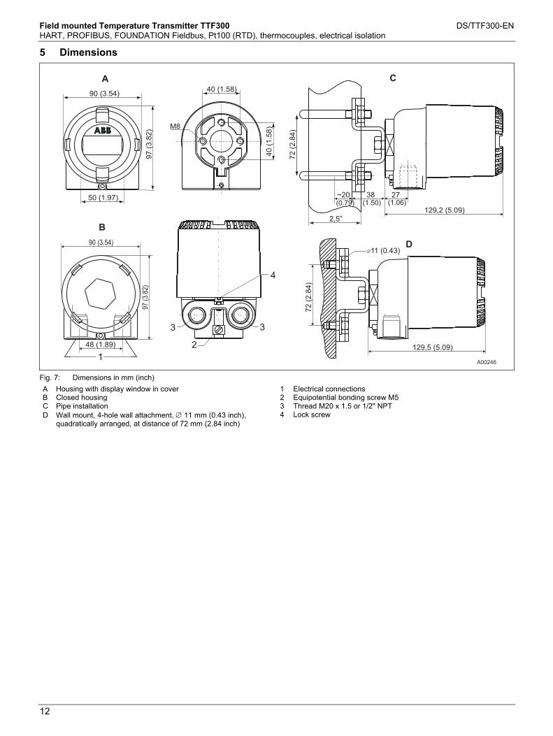
Field mounted Temperature Transmitter TTF300 DS/TTF300-EN HART, PROFIBUS, FOUNDATION Fieldbus, Pt100 (RTD), thermocouples, electrical isolation
12
Change from one to two columns
5 Dimensions
A00246
90 (3.54)
97
(3.8
2)
50 (1.97)
40 (1.58)
40
(1.5
8)M8
27
129,2 (5.09)
~20 38
72
(2.8
4)
97
(3.8
2)
90 (3.54)
48 (1.89) 129,5 (5.09)
11 (0.43)
(0.79) (1.50) (1.06)
2,5”
A
B
C
D
1
2
3
4
3
72
(2.8
4)
Fig. 7: Dimensions in mm (inch)
A Housing with display window in cover B Closed housing C Pipe installation D Wall mount, 4-hole wall attachment, 11 mm (0.43 inch),
quadratically arranged, at distance of 72 mm (2.84 inch)
1 Electrical connections 2 Equipotential bonding screw M5 3 Thread M20 x 1.5 or 1/2" NPT 4 Lock screw
Change from one to two columns

Field mounted Temperature Transmitter TTF300 DS/TTF300-EN HART, PROFIBUS, FOUNDATION Fieldbus, Pt100 (RTD), thermocouples, electrical isolation
13
Change from one to two columns Bestellangaben
6 Ordering information
Main order number
Add. order no.
Version number 1 – 6 7 8 9 10 11 12 13 XX
TTF300 Field Mounted Temperature Transmitter, Pt100 (RTD), Thermocouples, Electrical Isolation
TTF300 X X X X X X X XX
Explosion Protection Without explosion protection Y 0
ATEX Intrinsic Safety type of protection: Zone 0: II 1 G Ex ia IIC T6, Zone 1 (0): II 2 (1) G Ex [ia] ib IIC T6, Zone 1 (20): II 2 G (1D) Ex [iaD] ib IIC T6
E 1
ATEX Non-sparking type of protection: Zone 2 / Zone 22: II 3 G Ex nA II T6 and II 3 D IP 65 T 135 °C (Not for application in
hybrid mixtures) 1)
E 5
ATEX Dust Explosion Protection: Zone 20: II 1 D IP 65 T 135 °C
D 1
ATEX Dust Explosion Protection and Intrinsic Safety: Zone 0 / Zone 20: II 1 G Ex iA IIC T6 and II 1 D IP 65 T 135 °C (Not for application in
hybrid mixtures) 1)
D 2
ATEX Flameproof type of protection: Zone 1: II 2 G Ex d IIC T6
E 3
ATEX Flameproof and Intrinsic Safety type of protection: Zone 1 / Zone 0: II 2 G Ex d IIC T6 and II 1 G Ex ia IIC T6
E 4
IECEx Intrinsic Safety type of protection: Zone 0: Ex ia IIC T6, Zone 1 (0): Ex [ia] ib IIC T6, Zone 1 (20): Ex [iaD] ib IIC T6
H 1
FM Intrinsic Safety (IS): Class I, Div. 1+2, Groups A, B, C, D, Class II, E, F, G, Class III, Class I, Zone 0,
AEx ia IIC T6
L 1
FM Non-incendive (NI): Class I, Div. 2, Groups A, B, C, D, Class II, E, F, G, Class III
L 2
FM Explosionproof (XP): XP, NI, DIP, Class I, II, III, Div. 1+2, Groups A-G, factory sealed
L 3
FM Explosionproof (XP) and Intrinsic Safety (IS): XP, NI, DIP, Class I, II, III, Div. 1+2, Groups A-G, factory sealed and IS, Class I, Div. 1+2,
Groups A, B, C, D, Class II, E, F, G, Class III, Class I, Zone 0, AEx ia IIC T6
L 7
CSA Intrinsic Safety (IS): Class I, Div. 1+2, Groups A, B, C, D, Class II, E, F, G, Class III
R 1
CSA Non-incendive (NI): Class I, Div. 2, Groups A, B, C, D, Class II, E, F, G, Class III
R 2
CSA Explosionproof (XP): XP, NI, DIP, Class I, II, III, Div. 1+2, Groups A-G, factory sealed
R 3
CSA Explosionproof (XP) and Intrinsic Safety (IS): XP, NI, DIP, Class I, II, III, Div. 1+2, Groups A-G, factory sealed and IS, Class I, Div. 1+2,
Groups A, B, C, D, Class II, E, F, G, Class III
R 7
Russia - metrological approval 2) G 1
Russia - metrological approval and GOST Ex i 2) G 2
Russia - metrological approval and GOST Ex d 2) G 7
Russia - metrological approval and GOST Ex i and Ex d 2) G 8
Kazakhstan - metrological approval 2) G 3
Kazakhstan - metrological approval and GOST Ex i 2) G 4
Kazakhstan - metrological approval and GOST Ex d 2) M 1
Kazakhstan - metrological approval and GOST Ex i and Ex d 2) M 2
Ukraine - metrological approval 2) G 5
Ukraine - metrological approval and GOST Ex i 2) G 6
Ukraine - metrological approval and GOST Ex d 2) G 9
Ukraine - metrological approval and GOST Ex i and Ex d 2) M 3
Belarus - metrological approval 2) M 5
Belarus - metrological approval and GOST Ex i 2) M 6
Belarus - metrological approval and GOST Ex d 2) M 7
Belarus - metrological approval and GOST Ex i and Ex d 2) M 8
Continued on next page
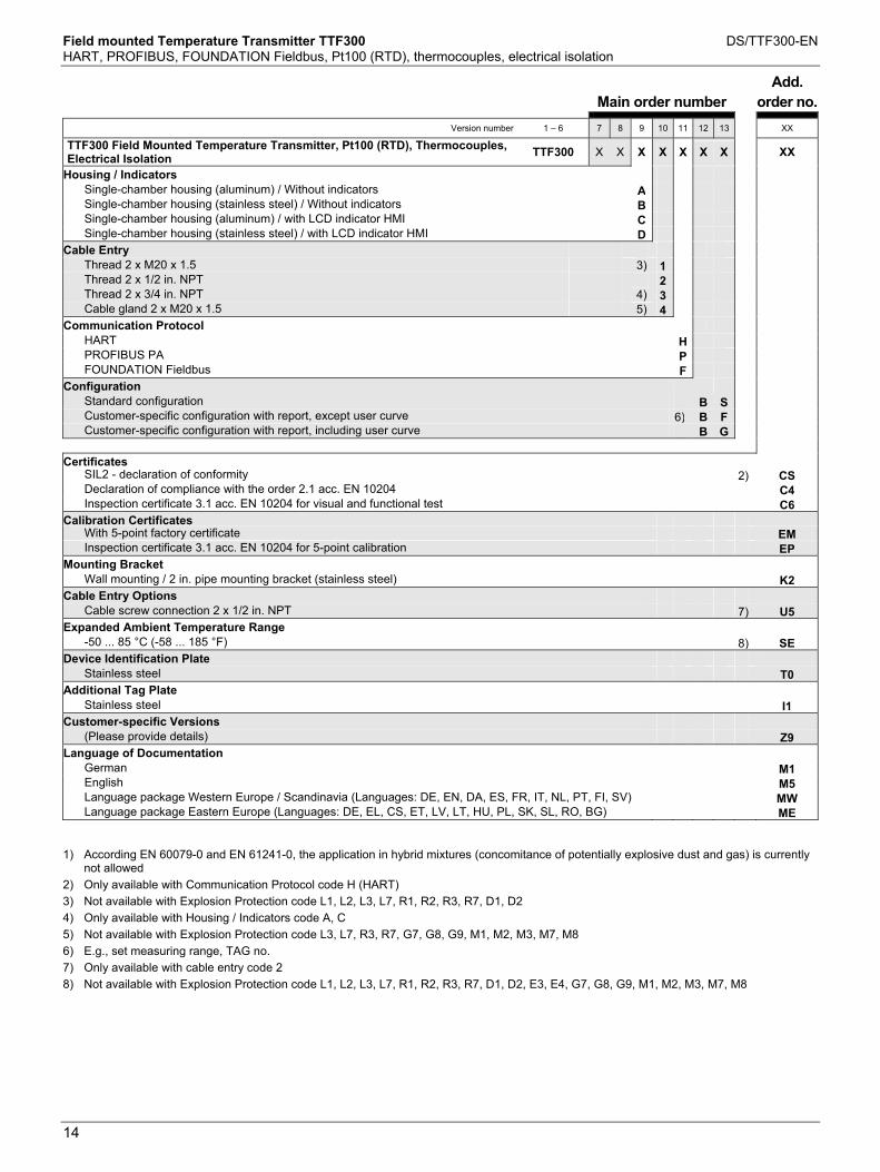
Field mounted Temperature Transmitter TTF300 DS/TTF300-EN HART, PROFIBUS, FOUNDATION Fieldbus, Pt100 (RTD), thermocouples, electrical isolation
14
Main order number
Add. order no.
Version number 1 – 6 7 8 9 10 11 12 13 XX
TTF300 Field Mounted Temperature Transmitter, Pt100 (RTD), Thermocouples, Electrical Isolation
TTF300 X X X X X X X XX
Housing / Indicators Single-chamber housing (aluminum) / Without indicators A Single-chamber housing (stainless steel) / Without indicators B Single-chamber housing (aluminum) / with LCD indicator HMI C Single-chamber housing (stainless steel) / with LCD indicator HMI D
Cable Entry Thread 2 x M20 x 1.5 3) 1 Thread 2 x 1/2 in. NPT 2 Thread 2 x 3/4 in. NPT 4) 3 Cable gland 2 x M20 x 1.5 5) 4
Communication Protocol HART H PROFIBUS PA P FOUNDATION Fieldbus F
Configuration Standard configuration B SCustomer-specific configuration with report, except user curve 6) B FCustomer-specific configuration with report, including user curve B G
Certificates
SIL2 - declaration of conformity 2) CSDeclaration of compliance with the order 2.1 acc. EN 10204 C4Inspection certificate 3.1 acc. EN 10204 for visual and functional test C6
Calibration Certificates With 5-point factory certificate EMInspection certificate 3.1 acc. EN 10204 for 5-point calibration EP
Mounting Bracket Wall mounting / 2 in. pipe mounting bracket (stainless steel) K2
Cable Entry Options Cable screw connection 2 x 1/2 in. NPT 7) U5
Expanded Ambient Temperature Range -50 ... 85 °C (-58 ... 185 °F) 8) SE
Device Identification Plate Stainless steel T0
Additional Tag Plate Stainless steel I1
Customer-specific Versions (Please provide details) Z9
Language of Documentation German M1English M5Language package Western Europe / Scandinavia (Languages: DE, EN, DA, ES, FR, IT, NL, PT, FI, SV) MWLanguage package Eastern Europe (Languages: DE, EL, CS, ET, LV, LT, HU, PL, SK, SL, RO, BG) ME
1) According EN 60079-0 and EN 61241-0, the application in hybrid mixtures (concomitance of potentially explosive dust and gas) is currently
not allowed
2) Only available with Communication Protocol code H (HART)
3) Not available with Explosion Protection code L1, L2, L3, L7, R1, R2, R3, R7, D1, D2
4) Only available with Housing / Indicators code A, C
5) Not available with Explosion Protection code L3, L7, R3, R7, G7, G8, G9, M1, M2, M3, M7, M8
6) E.g., set measuring range, TAG no.
7) Only available with cable entry code 2
8) Not available with Explosion Protection code L1, L2, L3, L7, R1, R2, R3, R7, D1, D2, E3, E4, G7, G8, G9, M1, M2, M3, M7, M8

Field mounted Temperature Transmitter TTF300 DS/TTF300-EN HART, PROFIBUS, FOUNDATION Fieldbus, Pt100 (RTD), thermocouples, electrical isolation
15
6.1 Documentation available for ordering
Description Order number
TTF300 Documentation CD-ROM 3KXT221001R0800
TTF300 Commissioning Instructions, English 3KXT221001R4401
TTF300 Commissioning Instructions, German 3KXT221001R4403
TTF300 Commissioning Instructions, Language package Western Europe / Scandinavia 3KXT221001R4493
TTF300 Commissioning Instructions, Language package Eastern Europe 3KXT221001R4494
7 Ex relevant specifications Change from one to two columns
7.1 TTF300-E1X, intrinsic safety ATEX
Explosion protection Approved for use in Zone 0, 1, and 2
Designation II 1G Ex ia IIC T6 (Zone 0) II 2(1)G Ex [ia] ib IIC T6 (Zone 1 [0]) II 2G(1D) Ex [iaD] ib IIC T6 (Zone 1 [20])
TTF300-E1H: EC type-examination test certificate PTB 05 ATEX 2017 X TTF300-E1P / E1F: EC type-examination test certificate PTB 09 ATEX 2016 X
7.2 TTF300-H1X, intrinsic safety IECEx
Designation Ex ia IIC T6 Ex [ia] ib IIC T6 Ex [iaD] ib IIC T6
TTF300-H1H: IECEx certificate of conformity IECEx PTB 09.0014X TTF300-H1P / H1F: IECEx certificate of conformity
7.3 Safety specifications for Intrinsic Safety ATEX / IECEx
Temperature table
Permissible ambient temperature range Temperature class Device category 1
use Device category 2 use
T6 -50 … 44 °C (-58 ... 111,2 °F)
-50 … 56 °C (-58 ... 132,8 °F)
T5 -50 … 56 °C (-58 ... 132,8 °F)
-50 … 71 °C (-58 ... 159,8 °F)
T4, T3, T2, T1 -50 … 60 °C (-58 ... 140,0 °F)
-50 … 85 °C (-58 ... 185,0 °F)
Intrinsic safety Ex ia IIC type of protection (part 1)
TTF300-E1P / -H1P
TTF300-E1F / -H1F
Supply circuit 1)
TTF300-E1H
TTF300-H1H
Supply circuit
FISCO ENTITY
Max. voltage Ui = 30 V Ui 17.5 V Ui 24.0 V
Short-circuit current
Ii = 130 mA Ii 183 mA 2) Ii 250 mA
Max. power Pi = 0.8 W Pi 2.56 W 2) Pi 1.2 W
Internal inductance Li = 0.5 mH Li 10 µH Li 10 µH
Internal capacitance
Ci = 5 nF Ci 5 nF Ci 5 nF
1) FISCO in accordance with IEC 60079-27 2) II B FISCO: Ii 380 mA, Pi 5.32 W
Intrinsic safety Ex ia IIC type of protection (part 2)
Measurement current circuit:
resistance thermometers,
resistors
Measurement current circuit:
thermocouples,
voltages
Max. voltage Uo = 6.5 V Uo = 1.2 V
Short-circuit current
Io = 25 mA Io = 50 mA
Max. power Po = 38 mW Po = 60 mW
Internal inductance Li = 0 mH Li = 0 mH
Internal capacitance
Ci = 49 nF Ci = 49 nF
Maximum permissible external inductance
Lo = 5 mH Lo = 5 mH
Maximum permissible external capacitance
Co = 1.55 µF Co = 1.05 µF
Intrinsic safety Ex ia IIC type of protection (part 3)
LCD indicator interface
Max. voltage Uo = 6.2 V
Short-circuit current Io = 65.2 mA
Max. power Po = 101 mW
Internal inductance Li = 0 mH
Internal capacitance Ci = 0 nF
Maximum permissible external inductance
Lo= 5 mH
Maximum permissible external capacitance
Co= 1.4 µF

Field mounted Temperature Transmitter TTF300 DS/TTF300-EN HART, PROFIBUS, FOUNDATION Fieldbus, Pt100 (RTD), thermocouples, electrical isolation
16
7.4 TTF300-E5X, non-sparking + dust explosion protection ATEX
Explosion protection Approved for use in Zone 2 and Zone 22
Designation
II 3G Ex nA II T6
II 3 D IP 65 T 135 °C
ABB manufacturer's declaration in accordance with ATEX Directive
Temperature table
Temperature class
Device category 3 use
T6 -50 … 56 °C (-58 ... 132,8 °F)
T5 -50 … 71 °C (-58 ... 159,8 °F)
T4 -50 … 85 °C (-58 ... 185,0 °F)
7.5 TTF300-D1X, dust explosion protection ATEX
Explosion protection Approved for use in Zone 20
Designation II 1D Ex tD A20 IP66 T135°C
EC type-examination test certificate BVS 06 ATEX E 029
7.6 TTF300-D2X, dust explosion protection + intrinsic safety ATEX
Explosion protection Approved for use in Zone 20 and Zone 0
Designation II 1D Ex tD A20 P66 T135°C II 1G Ex ia IIC T6
EC type-examination test certificate BVS 06 ATEX E 029
EC type-examination test certificate PTB 05 ATEX 2017 X
EC type-examination test certificate PTB 05 ATEX 2016 X
7.7 TTF300-E3X, flameproof enclosure ATEX
Explosion protection Approved for use in Zone 1
Designation II 2G Ex d IIC T6
EC type-examination test certificate PTB 99 ATEX 1144
7.8 TTF300-E4X, flameproof enclosure + intrinsic safety ATEX
Explosion protection Approved for use in Zone 1
Designation II 2G Ex d IIC T6 II 1G Ex ia IIC T6
EC type-examination test certificate PTB 99 ATEX 1144
EC type-examination test certificate PTB 05 ATEX 2017 X
EC type-examination test certificate PTB 05 ATEX 2016 X
7.9 TTF300-L1X, intrinsically safe FM
Class I, Div. 1 + 2, Groups A, B, C, D Class I, Zone 0, AEx ia IIC TTF300-L1H: Control Drawing: SAP_214832 TTF300-L1P: Control Drawing: TTF300-L1..P (IS) TTF300-L1F: Control Drawing: TTF300-L1..F (IS)
7.10 TTF300-L2X, non-incendive FM
Class I, Div. 2, Groups A, B, C, D Class I Zone 2 Group IIC T6 TTF300-L2H: Control Drawing: SAP_214828 Control Drawing: SAP_214830 TTF300-L2P: Control Drawing: TTF300-L2..P (NI_PS), TTF300-L2..P (NI_AA) TTF300-L2F: Control Drawing: TTF300-L2..F (NI_PS), TTF300-L2..F (NI_AA)
7.11 TTF300-L3X, explosion proof FM
XP,NI, DIP Class I, II, III, Div. 1 + 2, Groups A-G, factory sealed
7.12 TTF300-L7X, explosion proof + intrinsically safe FM
XP, NI, DIP Class I, II, III, Div. 1 + 2, Groups A-G, factory sealed Class I, Div. 1 + 2, Groups A, B, C, D Class I, Zone 0, AEx ia IIC T6 TTF300-L1H: Control Drawing: SAP_214832 TTF300-L1P: Control Drawing: TTF300-L1..P (IS) TTF300-L1F: Control Drawing: TTF300-L1..F (IS)
7.13 TTF300-R1X, intrinsically safe CSA
Class I, Div. 1 + 2, Groups A, B, C, D Class I, Zone 0, Ex ia IIC TTF300-R1H: Control Drawing: SAP_214825 TTF300-R1P: Control Drawing: TTF300-R1..P (IS) TTF300-R1F: Control Drawing: TTF300-R1..F (IS)
7.14 TTF300-R2X, non-incendive CSA
Class I, Div. 2, Groups A, B, C, D TTF300-R2H: Control Drawing: SAP_214827 Control Drawing: SAP_214895 TTF300-R2P: Control Drawing: TTF300-R2..P (NI_PS), TTF300-R2..P (NI_AA) TTF300-R2F: Control Drawing: TTF300-R2..F (NI_PS), TTF300-R2..F (NI_AA)
7.15 TTF300-R3X, explosion proof CSA
XP,NI, DIP Class I, II, III, Div. 1 + 2, Groups A-G, factory sealed
7.16 TTF300-R7X, explosion proof + intrinsically safe CSA
XP,NI, DIP Class I, II, III, Div. 1 + 2, Groups A-G, factory sealed Class I, Div. 1 + 2, Groups A, B, C, D Class I, Zone 0, Ex ia Group IIC T6 TTF300-R1H: Control Drawing: SAP_214825 TTF300-R1P: Control Drawing: TTF300-R1..P (IS) TTF300-R1F: Control Drawing: TTF300-R1..F (IS)
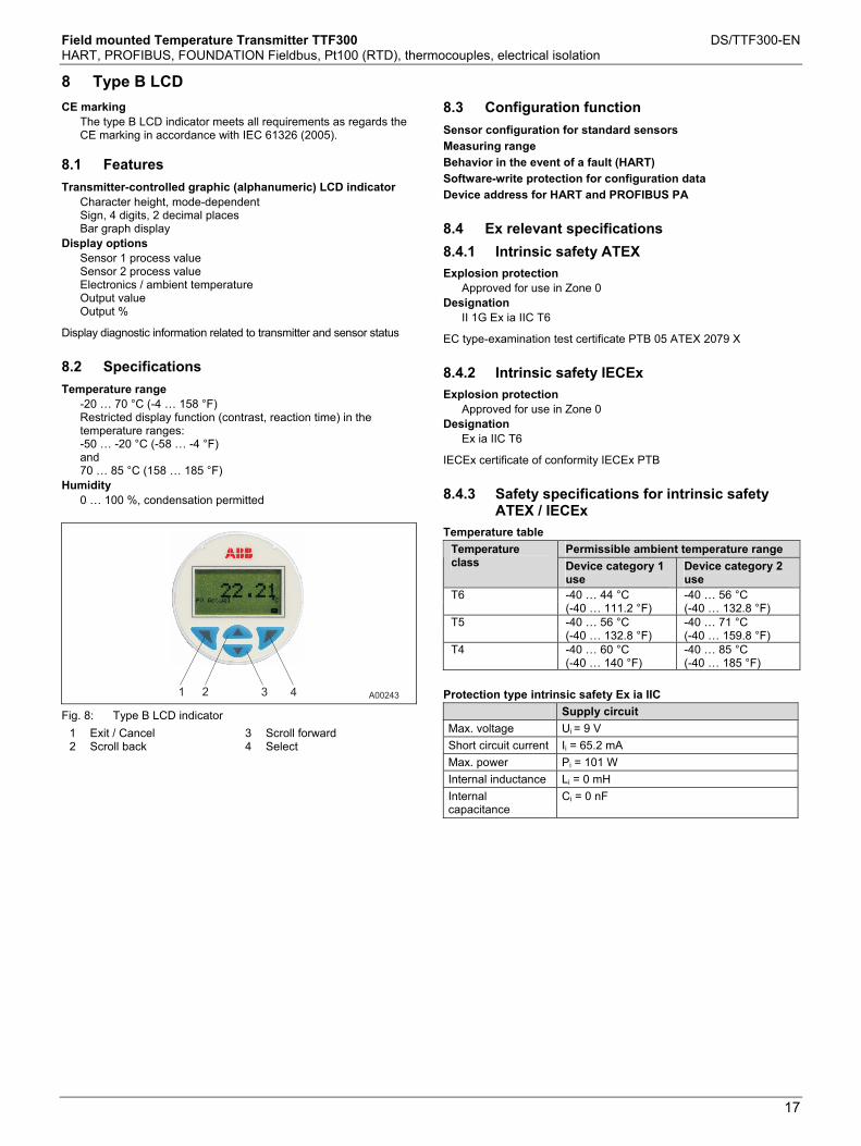
Field mounted Temperature Transmitter TTF300 DS/TTF300-EN HART, PROFIBUS, FOUNDATION Fieldbus, Pt100 (RTD), thermocouples, electrical isolation
17
Change from one to two columns
8 Type B LCD Change from one to two columns
CE marking The type B LCD indicator meets all requirements as regards the CE marking in accordance with IEC 61326 (2005).
8.1 Features
Transmitter-controlled graphic (alphanumeric) LCD indicator Character height, mode-dependent Sign, 4 digits, 2 decimal places Bar graph display
Display options Sensor 1 process value Sensor 2 process value Electronics / ambient temperature Output value Output %
Display diagnostic information related to transmitter and sensor status
8.2 Specifications
Temperature range -20 … 70 °C (-4 … 158 °F) Restricted display function (contrast, reaction time) in the temperature ranges: -50 … -20 °C (-58 … -4 °F) and 70 … 85 °C (158 … 185 °F)
Humidity 0 … 100 %, condensation permitted
A002431 2 3 4
Fig. 8: Type B LCD indicator
1 Exit / Cancel 2 Scroll back
3 Scroll forward 4 Select
8.3 Configuration function
Sensor configuration for standard sensors
Measuring range
Behavior in the event of a fault (HART)
Software-write protection for configuration data
Device address for HART and PROFIBUS PA
8.4 Ex relevant specifications
8.4.1 Intrinsic safety ATEX
Explosion protection Approved for use in Zone 0
Designation II 1G Ex ia IIC T6
EC type-examination test certificate PTB 05 ATEX 2079 X
8.4.2 Intrinsic safety IECEx
Explosion protection Approved for use in Zone 0
Designation Ex ia IIC T6
IECEx certificate of conformity IECEx PTB
8.4.3 Safety specifications for intrinsic safety ATEX / IECEx
Temperature table
Permissible ambient temperature range Temperature class Device category 1
use Device category 2 use
T6 -40 … 44 °C -40 … 56 °C (-40 … 111.2 °F) (-40 … 132.8 °F) T5 -40 … 56 °C -40 … 71 °C (-40 … 132.8 °F) (-40 … 159.8 °F) T4 -40 … 60 °C -40 … 85 °C (-40 … 140 °F) (-40 … 185 °F)
Protection type intrinsic safety Ex ia IIC
Supply circuit
Max. voltage Ui = 9 V
Short circuit current Ii = 65.2 mA
Max. power Pi = 101 W
Internal inductance Li = 0 mH
Internal capacitance
Ci = 0 nF

Field mounted Temperature Transmitter TTF300 DS/TTF300-EN HART, PROFIBUS, FOUNDATION Fieldbus, Pt100 (RTD), thermocouples, electrical isolation
18
8.4.4 Intrinsically Safe FM
I.S. Class I Div 1 and Div 2, Group: A, B, C, D or I.S. Class I Zone 0 AEx ia IIC T* Temp. Ident: T6 Tamb 56 °C, T4 Tamb 85 °C Ui / Vmax = 9V, Ii / Imax < 65.2 mA, Pi = 101 mW Ci = 0.4 µF; Li = 0 Control Drawing: SAP_214 748
8.4.5 Non-Incendive FM
N.I. Class I Div 2, Group: A, B, C, D or Ex nL IIC T*, Class I Zone 2 Temp. Ident: T6 Tamb 60 °C, T4 Tamb 85 °C Ui / Vmax = 9V, Ii / Imax < 65.2 mA, Pi = 101 mW Ci = 0.4 µF; Li = 0 Control Drawing: SAP_214 751
8.4.6 Intrinsically Safe CSA
I.S. Class I Div 1 and Div 2; Group: A, B, C, D or I.S Zone 0 Ex ia IIC T* *Temp. Ident T6 Tamb 56 C, T4 Tamb 85 °C Ui / Vmax = 9V, Ii / Imax < 65,2 mA; Pi = 101 mW Ci < 0,4 Fµ, Li = 0 Control Drawing: SAP_214 749
8.4.7 Non-Incendive CSA
N.I. Class I Div 2, Group: A, B, C, D or Ex nL IIC T*, Class I Zone 2 *Temp. Ident T6, Tamb 60 °C, T4 Tamb 85 °C Ui / Vmax = 9V, Ii / Imax < 65.2 mA, Pi = 101 mW Ci < 0.4 µF, Li = 0 Control Drawing: SAP_214 750
Change from one to two columns

Field mounted Temperature Transmitter TTF300 DS/TTF300-EN HART, PROFIBUS, FOUNDATION Fieldbus, Pt100 (RTD), thermocouples, electrical isolation
19
9 Order form configuration
9.1 HART device design: Data relating to customer-specific configuration
Configuration Selection
Number of sensors 1 sensor (standard) 2 sensors
Measurement type
(for 2-sensor selection only)
Redundancy / sensor backup
Sensor drift monitoring .....°C / K Sensor drift differential ....s time limit for drift overshoot
Differential measurement
Mean measurement
IEC 60751
JIS C1604-89
MIL-T-24388
DIN 43760
Cu
Resistance thermometer
Pt10 Pt50 Pt100 (standard)
Pt200 Pt500 Pt1000
Pt10 Pt50 Pt100
Pt10 Pt50 Pt100 Pt200 Pt500 Pt1000
Ni50 Ni100 Ni120 Ni1000
Cu10 Cu100
Resistance measurement
0 … 500 0 … 5000
IEC 60584
DIN 43710
ASTM E-988
Thermocouple
Type K Type J Type N Type R Type S Type T
Type E Type B
Type L Type U
Type C Type D
Voltage measurement -125 … 125 mV -125 … 1100 mV
Sensor circuit
(for resistance thermometer and resistance measurement only)
Two-wire Three-wire (standard) Four-wire
Two-wire circuit: Compensation of sensor line resistance max. 100
Sensor 1: .......... Sensor 2: ..........
Reference point
(for thermocouples only)
Internal (for standard thermocouples except type B) None (type B)
External / temperature: ....... °C
Measuring range Measuring start: .......... (Standard: 0)
Measuring end: .......... (Standard: 100 )
Unit Celsius (standard) Fahrenheit Rankine Kelvin
Characteristic behavior Rising 4 ... 20 mA (standard) Falling 20 ... 4 mA
Output behavior for error Override / 22 mA (standard)
Underdrive / 3.6 mA
Output attenuation (T63) Off (standard) ........ seconds (1 … 100 s)
Sensor number Sensor 1................ Sensor 2................
Resistor value at 0 °C / Ro
Callendar-Van Dusen coefficient A
Callendar-Van Dusen coefficient B
Callendar-Van Dusen coefficient C
(optional, for resistance thermometers only)
Sensor 1: Ro: ................ Sensor 2: Ro: ................
A: …......... A: ….........
B: …......... B: ….........
C: …......... C: ….........
User characteristics based on linearization table
Based on attached table of variate pairs
TAG number ..........................................................................................................................................
Software write protection Off (standard) On
"Maintenance required" alarm pulse or continuous signaling in accordance with NE 107
Off (standard) pulse width ......s (0.5 .... 59.5 s increment 0.5 s) Continuous signal

Field mounted Temperature Transmitter TTF300 DS/TTF300-EN HART, PROFIBUS, FOUNDATION Fieldbus, Pt100 (RTD), thermocouples, electrical isolation
20
9.2 PROFIBUS PA / FOUNDATION Fieldbus device design
Configuration Selection
Number of sensors 1 sensor (standard) 2 sensors
Measurement type
(for 2-sensor selection only)
Sensor redundancy / sensor backup
Sensor drift monitoring .....°C / K sensor drift differential ....s time limit for drift overshoot
Differential measurement
Mean measurement
IEC 60751
JIS C1604-89
MIL-T-24388
DIN 43760
Cu
Resistance thermometer
Pt10 Pt50 Pt100 (standard)
Pt200 Pt500 Pt1000
Pt10 Pt50 Pt100
Pt10 Pt50 Pt100 Pt200 Pt500 Pt1000
Ni50 Ni100 Ni120 Ni1000
Cu10 Cu100
Resistance measurement
0 … 500 0 … 5000
IEC 60584
DIN 43710
ASTM E-988
Thermocouple
Type K Type J Type N Type R Type S Type T
Type E Type B
Type L Type U
Type C Type D
Voltage measurement -125 … 125 mV -125 … 1100 mV
Sensor circuit
(for resistance thermometer and resistance measurement only)
Two-wire Three-wire (standard) Four-wire
Two-wire circuit: compensation of sensor line resistance max. 100
Sensor 1: .......... Sensor 2: ..........
Reference point
(for thermocouples only)
Internal (for standard thermocouples except type B) None (type B)
External / temperature: ....... °C
Unit Celsius (standard) Fahrenheit Rankine Kelvin
Resistor value at 0 °C / Ro
Callendar-Van Dusen coefficient A
Callendar-Van Dusen coefficient B
Callendar-Van Dusen coefficient C
(optional, for resistance thermometers only)
Sensor 1: Ro: ................ Sensor 2: Ro: ................
A: …......... A: ….........
B: …......... B: ….........
C: …......... C: ….........
IDENT_number (PROFIBUS) Device-specific 0x3470 (standard) Profile 0x9700 (1 AI block)
Bus address PROFIBUS PA PA: 0 ... 125 Standard PA: 126
TAG number ..........................................................................................................................................
Software write protection Off (standard) On


Contact us
DS
/TTF
300-
ENR
ev.C
09.2
011Note
We reserve the right to make technical changes or modify the contents of this document without prior notice. With regard to purchase orders, the agreed particulars shall prevail. ABB does not accept any responsibility whatsoever for potential errors or possible lack of information in this document. We reserve all rights in this document and in the subject matter and illustrations contained therein. Any reproduction, disclosure to third parties or utilization of its contents - in whole or in parts – is forbidden without prior written consent of ABB. Copyright© 2011 ABB All rights reserved
ABB Ltd. Salterbeck Trading Estate Workington, Cumbria CA14 5DS UK Phone: +44 (0)1946 830 611 Fax: +44 (0)1946 832 661 ABB Inc. 125 E. County Line Road Warminster PA 18974 USA Phone: +1 215 674 6000 Fax: +1 215 674 7183 ABB Automation Products GmbH Schillerstr. 72 32425 Minden Germany Phone: +49 551 905-534 Fax: +49 551 905-555 www.abb.com
3KXT221001R1001

Data Sheet DS/TTR200-EN Rev. B
TTR200 Rail mounted Temperature Transmitter
HART, Pt100 (RTD), Thermocouples, Electrical isolation Input — Resistance thermometer — Thermocouples — Resistance-type transmitters — Voltages, mV voltages Output — 4 ... 20 mA, HART Measurement deviation — 0.1 K Sensor error adjustment
Continuous sensor monitoring and self-monitoring — Two function LEDs — Supply voltage monitoring — Wire break and corrosion monitoring in accordance with
NE 89 Device safety in accordance with NE 53 SIL2 acc. to IEC 61508 Approvals for explosion protection — ATEX, IECEx, Zone 0 — FM / CSA Configuration — DTM — EDD
Contents
Rail mounted Temperature Transmitter TTR200 DS/TTR200-EN HART, Pt100 (RTD), thermocouples, Electrical isolation
2
Contents 1 Specifications ......................................................................................................................................................3
1.1 Input................................................................................................................................................................3 1.2 Output.............................................................................................................................................................3 1.3 Power supply (polarity safe) ...........................................................................................................................3
2 General information ............................................................................................................................................4 2.1 Ambient conditions .........................................................................................................................................4 2.2 ElectroMagnetic Compatibility........................................................................................................................4 2.3 Interference immunity.....................................................................................................................................4 2.4 Mechanical design..........................................................................................................................................4 2.5 SIL functional safety .......................................................................................................................................4 2.6 Measuring accuracy .......................................................................................................................................5 2.7 Operating influences ......................................................................................................................................6
3 Communication ...................................................................................................................................................7 3.1 Configuration parameters...............................................................................................................................7 3.2 HART..............................................................................................................................................................7
4 Electrical connections ........................................................................................................................................8 5 Dimensions ..........................................................................................................................................................8 6 Ordering information...........................................................................................................................................9
6.1 Documentation available for ordering ............................................................................................................9 7 Ex relevant specifications ................................................................................................................................10
7.1 TTR200-E1, Intrinsic Safety ATEX...............................................................................................................10 7.2 TTR200-H1, Intrinsic Safety IECEx..............................................................................................................10 7.3 Safety specifications for Intrinsic Safety ATEX / IECEx...............................................................................10 7.4 TTR200-E2, Non-Sparking ATEX ................................................................................................................10 7.5 TTR200-L6, intrinsically safe FM .................................................................................................................10 7.6 TTR200-L6, non-incendive FM ....................................................................................................................10 7.7 TTR200-R6, intrinsically safe CSA...............................................................................................................10 7.8 TTR200-R6, non-incendive CSA..................................................................................................................10
8 Order form configuration..................................................................................................................................11
Data Sheet Rail mounted Temperature Transmitter TTR200
HART,
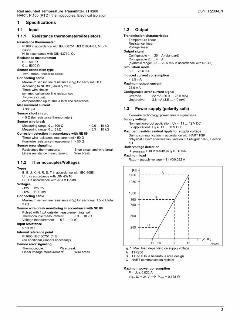
Rail mounted Temperature Transmitter TTR200 DS/TTR200-EN HART, Pt100 (RTD), thermocouples, Electrical isolation
3
1 Specifications Change from one to two columns
1.1 Input
1.1.1 Resistance thermometers/Resistors
Resistance thermometer Pt100 in accordance with IEC 60751, JIS C1604-81, MIL-T-24388, Ni in accordance with DIN 43760, Cu
Resistance measurement 0 … 500 Ω 0 … 5000 Ω
Sensor connection type Two-, three-, four-wire circuit
Connecting cable Maximum sensor line resistance (RW) for each line 50 Ω according to NE 89 (January 2009) Three-wire circuit: symmetrical sensor line resistances Two-wire circuit: compensation up to 100 Ω total line resistance
Measurement current < 300 µA
Sensor short circuit < 5 Ω (for resistance thermometer)
Sensor wire break Measuring range: 0 ... 500 Ω > 0.6 ... 10 kΩ Measuring range: 0 ... 5 kΩ > 5.3 ... 10 kΩ
Corrosion detection in accordance with NE 89 Three-wire resistance measurement > 50 Ω Four-wire resistance measurement > 50 Ω
Sensor error signaling Resistance thermometers: Short circuit and wire break Linear resistance measurement: Wire break
1.1.2 Thermocouples/Voltages
Types B, E, J, K, N, R, S, T in accordance with IEC 60584 U, L in accordance with DIN 43710 C, D in accordance with ASTM E-988
Voltages -125 ... 125 mV -125 ... 1100 mV
Connecting cable Maximum sensor line resistance (RW) for each line: 1.5 kΩ, total: 3 kΩ
Sensor wire-break monitoring in accordance with NE 89 Pulsed with 1 µA outside measurement interval Thermocouple measurement 5.3 ... 10 kΩ Voltage measurement 5.3 ... 10 kΩ
Input resistance > 10 MΩ
Internal reference point Pt1000, IEC 60751 Cl. B (no additional jumpers necessary)
Sensor error signaling Thermocouple: Wire break Linear voltage measurement: Wire break
1.2 Output
Transmission characteristics Temperature linear Resistance linear Voltage linear
Output signal Configurable 4 ... 20 mA (standard) Configurable 20 ... 4 mA (dynamic range: 3.8 ... 20.5 mA in accordance with NE 43)
Simulation mode 3.5 ... 23.6 mA
Induced current consumption < 3.5 mA
Maximum output current 23.6 mA
Configurable error current signal Override 22 mA (20.0 … 23.6 mA) Underdrive 3.6 mA (3.5 … 4.0 mA)
1.3 Power supply (polarity safe) Change from one to two columns
Two-wire technology; power lines = signal lines Supply voltage
Non ignition-proof application: US = 11 ... 42 V DC Ex applications: US = 11 ... 30 V DC
Max. permissible residual ripple for supply voltage During communication in accordance with HART FSK "Physical Layer" specification, version 8.1 (August 1999) Section 8.1
Undervoltage detection UTerminal-Mu < 10 V results in Ia = 3.6 mA
Maximum load RLoad = (supply voltage – 11 V)/0.022 A
A0000111 16 4230
A
[V DC][V DC]
[ ][ ]
250
500
750
860
1000
1250
1400
B
C
Fig. 1: Max. load depending on supply voltage
A TTR200 B TTR200 In ia hazardous area design C HART communication resistor
Maximum power consumption
P = Us x 0.022 A e.g., Us = 24 V → Pmax = 0.528 W
Rail mounted Temperature Transmitter TTR200 DS/TTR200-EN HART, Pt100 (RTD), thermocouples, Electrical isolation
4
2 General information Change from one to two columns
CE Marking The TTR200 meets all requirements for the CE mark in accordance with IEC 61326 (2006)
Electrical isolation 3.5 kV DC (approx. 2.5 kV AC) 60 s, input to output
MTBF time 28 years at 60 °C ambient temperature
Input filter 50 / 60 Hz
Switch-on delay < 10 s (Ia ≤ 3.6 mA during starting cycle)
Warm-up time 5 minutes
Ramp-up time t90 400 … 1000 ms
Rate updated 10/s, independent of sensor type and sensor circuit
Output filter Digital filter 1st order: 0 ... 100 s
2.1 Ambient conditions
Ambient temperature Standard: -40 … 85 °C (-40 … 185 °F) Restricted range with hazardous area design
Transport/storage temperature -40 … 85 °C (-40 … 185 °F)
Climate class Cx -40 … 85 °C (-40 … 185 °F) at 5 … 95 % relative humidity, DIN EN 60654-1
Max. permissible humidity 100 % relative humidity, IEC 60068-2-30
Vibration resistance 10 … 2000 Hz at 5 g, IEC 60068-2-6, during operation and transport
Shock gn = 30, IEC 68-2-27, during operation and transport
Ingress protection IP 20 or IP class of the bay
2.2 ElectroMagnetic Compatibility
Emitted interference in accordance with IEC EN 61326 (2006) and Namur NE 21 (February 2004)
2.3 Interference immunity
Interference-immune in accordance with IEC 61326 (2006) and Namur NE 21 (August 2007) Pt100: measuring range 0 ... 100 °C (32 ... 212 °F), span 100 K
Type of test Testing accuracy
Influence
Burst to signal/data lines 2 kV < 0.5 % Static discharge:
• Contact plate (indirect) • Supply terminals 1) • Sensor terminals 1)
8 kV 6 kV 4 kV
No No No
Radiated field 80 MHz ... 2 GHz 10 V/m < 0.5 %
Coupling 150 kHz … 80 MHz 10 V < 0.5 %
Surge: between the supply lines 0.5 kV No malfunction
Line to ground 1 kV No malfunction 1) Air discharge (at 1 mm (0.04 inch) distance)
2.4 Mechanical design Change from one to two columns
Dimensions See Section 5, "Dimensions"
Weight 180 g
Material Housing: polycarbonate Color: Gray RAL 9002 Sealing compound: Hard sealing compound
Installation conditions Installation position: No limitations Installation options: 35 mm rail mounting acc. to EN 60175
Electrical connection Terminals (captive screws) with screw connections, plug-in Lines up to max. 2.5 mm2 (AWG 14)
2.5 SIL functional safety
Conforms with IEC 61508 as regards use in safety-related applications, up to and including SIL 2.

Rail mounted Temperature Transmitter TTR200 DS/TTR200-EN HART, Pt100 (RTD), thermocouples, Electrical isolation
5
Change from one to two columns
2.6 Measuring accuracy
Includes linearity deviation, reproducibility/hysteresis at 23 °C (73.4 °F) ± 5 K and 20 V supply voltage
Information on measuring accuracy corresponds to 3 σ (Gaussian distribution)
Input element
Standard Sensor Measuring range limits Minimum spanDigital measuring accuracy (24-bit A/D converter)
D/A measuring accuracy 1)
(16-bit DA) Resistance thermometer/resistor IEC 60 751 Pt10
Pt50 Pt100 Pt200 Pt500 Pt1000
(a=0,003850) (a=0,003850) (a=0,003850) 2) (a=0,003850) (a=0,003850) (a=0,003850)
-200 ... 850 °C -200 ... 850 °C -200 ... 850 °C-200 ... 850 °C -200 ... 850 °C -200 ... 850 °C
(-328 ... 1562 °F) (-328 ... 1562 °F) (-328 ... 1562 °F) (-328 ... 1562 °F) (-328 ... 1562 °F) (-328 ... 1562 °F)
10 °C 10 °C 10 °C 10 °C 10 °C 10 °C
(18 °F) (18 °F) (18 °F) (18 °F) (18 °F) (18 °F)
± 0,80 °C ± 0,16 °C ± 0,08 °C ± 0,24 °C ± 0,16 °C ± 0,08 °C
(± 1,44 °F) (± 0,29 °F) (± 0,14 °F) (± 0,43 °F) (± 0,29 °F) (± 0,14 °F)
± 0,05 % ± 0,05 % ± 0,05 % ± 0,05 % ± 0,05 % ± 0,05 %
JIS C1604-81 Pt10 Pt50 Pt100
(a=0,003916) (a=0,003916) (a=0,003916)
-200 ... 645 °C -200 ... 645 °C -200 ... 645 °C
(-328 ... 1193 °F) (-328 ... 1193 °F) (-328 ... 1193 °F)
10 °C 10 °C 10 °C
(18 °F) (18 °F) (18 °F)
± 0,80 °C ± 0,16 °C ± 0,08 °C
(± 1,44 °F) (± 0,29 °F) (± 0,14 °F)
± 0,05 % ± 0,05 % ± 0,05 %
MIL-T-24388 Pt10 Pt50 Pt100 Pt200 Pt500 Pt1000
(a=0,003920) (a=0,003920) (a=0,003920) (a=0,003920) (a=0,003920) (a=0,003920)
-200 ... 850 °C -200 ... 850 °C -200 ... 850 °C -200 ... 850 °C -200 ... 850 °C -200 ... 850 °C
(-328 ... 1562 °F) (-328 ... 1562 °F) (-328 ... 1562 °F) (-328 ... 1562 °F) (-328 ... 1562 °F) (-328 ... 1562 °F)
10 °C 10 °C 10 °C 10 °C 10 °C 10 °C
(18 °F) (18 °F) (18 °F) (18 °F) (18 °F) (18 °F)
± 0,80 °C ± 0,16 °C ± 0,08 °C ± 0,24 °C ± 0,16 °C ± 0,08 °C
(± 1,44 °F) (± 0,29 °F) (± 0,14 °F) (± 0,43 °F) (± 0,29 °F) (± 0,14 °F)
± 0,05 % ± 0,05 % ± 0,05 % ± 0,05 % ± 0,05 % ± 0,05 %
DIN 43760 Ni50 Ni100 Ni120 Ni1000
(a=0,006180) (a=0,006180) (a=0,006180) (a=0,006180)
-60 ... 250 °C -60 ... 250 °C -60 ... 250 °C -60 ... 250 °C
(-76 ... 482 °F) (-76 ... 482 °F) (-76 ... 482 °F) (-76 ... 482 °F)
10 °C 10 °C 10 °C 10 °C
(18 °F) (18 °F) (18 °F) (18 °F)
± 0,16 °C ± 0,08 °C ± 0,08 °C ± 0,08 °C
(± 0,29 °F) (± 0,14 °F) (± 0,14 °F) (± 0,14 °F)
± 0,05 % ± 0,05 % ± 0,05 % ± 0,05 %
Cu10 Cu100
(a=0,004270) (a=0,004270)
-50 ... 200 °C -50 ... 200 °C
(-58 ... 392 °F) (-58 ... 392 °F)
10 °C 10 °C
(18 °F) (18 °F)
± 0,80 °C ± 0,08 °C
(± 1,44 °F) (± 0,14 °F)
± 0,05 % ± 0,05 %
Resistance measurement Resistance measurement
0 ... 500 Ω 0 ... 5000 Ω
4 Ω 40 Ω
± 32 mΩ ± 320 mΩ
± 0,05 % ± 0,05 %
Thermocouples 3)/voltages IEC 60584 Type K
Type J Type N Type T Type E Type R Type S Type B
(Ni10Cr-Ni5) (Fe-Cu45Ni) (Ni14CrSi-NiSi) (Cu-Cu45Ni) (Ni10Cr-Cu45Ni) (Pt13Rh-Pt) (Pt10Rh-Pt) (Pt30Rh-Pt6Rh)
-270 ... 1372 °C -210 ... 1200 °C -270 ... 1300 °C -270 ... 400 °C -270 ... 1000 °C -50 ... 1768 °C -50 ... 1768 °C -0 ... 1820 °C
(-454 ... 2502 °F) (-346 ... 2192 °F) (-454 ... 2372 °F) (-454 ... 752 °F) (-454 ... 1832 °F) (-58 ... 3215 °F) (-58 ... 3215 °F) (32 ... 3308 °F)
50 °C 50 °C 50 °C 50 °C 50 °C 100 °C100 °C100 °C
(90 °F) (90 °F) (90 °F) (90 °F) (90 °F) (180 °F)(180 °F)(180 °F)
± 0,35 °C ± 0,35 °C ± 0,35 °C ± 0,35 °C ± 0,35 °C ± 0,95 °C ± 0,95 °C ± 0,95 °C
(± 0,63 °F) (± 0,63 °F) (± 0,63 °F) (± 0,63 °F) (± 0,63 °F) (± 1,71 °F) (± 1,71 °F) (± 1,71 °F)
± 0,05 % ± 0,05 % ± 0,05 % ± 0,05 % ± 0,05 % ± 0,05 % ± 0,05 % ± 0,05 %
DIN 43710 Type L Type U
(Fe-CuNi) (Cu-CuNi)
-200 ... 900 °C -200 ... 600 °C
(-328 ... 1652 °F) (-328 ... 1112 °F)
50 °C 50 °C
(90 °F) (90 °F)
± 0,35 °C ± 0,35 °C
(± 0,63 °F) (± 0,63 °F)
± 0,05 % ± 0,05 %
ASTM E-988 Type C
Type D -0 ... 2315 °C -0 ... 2315 °C
(32 ... 4200 °F) (32 ... 4200 °F)
100 °C100 °C
(180 °F)(180 °F)
± 1,35 °C ± 1,35 °C
(± 2,43 °F) (± 2,43 °F)
± 0,05 % ± 0,05 %
Voltage measurement Voltage measurement
-125 ... 125 mV -125 ... 1100 mV
2 mV 20 mV
± 12 µV ± 120 µV
± 0,05 % ± 0,05 %
Long-term drift ± 0.05 °C (±0.09 °F) or ± 0.05 % 1) per year, the larger value applies. 1) Percentages refer to the configured measuring span 2) Standard model 3) Include the internal reference point error for digital measuring accuracy: Pt1000, IEC 60751 Cl. B 4) Without reference point error

Rail mounted Temperature Transmitter TTR200 DS/TTR200-EN HART, Pt100 (RTD), thermocouples, Electrical isolation
6
2.7 Operating influences
The percentages refer to the configured measuring span. Supply voltage influence/load influence: within the specified limits for the voltage/load, the total influence is less than 0.001 % per volt
Common-mode interference: no influence up to 100 Veff (50 Hz) or 50 V DC
Ambient temperature influence: based on 23 °C (73.4 °F) for ambient temperature range -40 ... 85 °C (-40 ... 185 °F)
Sensor Influence of ambient temperature per 1 °C (1.8 °F) deviation to 23 °C (73.4 °F) for digital measurement
Influence of ambient temperature 1) 2)
per 1 °C (1.8 °F) deviation to 23 °C (73.4 °F) for D/A converter
Resistance thermometer for two-, three-, four-wire circuits
Pt10 Pt50 Pt100 Pt200 Pt500 Pt1000
IEC, JIS, MIL IEC, JIS, MIL IEC, JIS, MIL IEC, MIL IEC, MIL IEC, MIL
± 0,04 °C (± 0,072 °F) ± 0,008 °C (± 0,014 °F) ± 0,004 °C (± 0,007 °F) ± 0,02 °C (± 0,036 °F) ± 0,008 °C (± 0,014 °F) ± 0,004 °C (± 0,007 °F)
± 0,003 % ± 0,003 % ± 0,003 % ± 0,003 % ± 0,003 % ± 0,003 %
Ni50 Ni100 Ni120 Ni1000
DIN 43760 DIN 43760 DIN 43760 DIN 43760
± 0,008 °C (± 0,014 °F) ± 0,004 °C (± 0,007 °F) ± 0,003 °C (± 0,005 °F) ± 0,004 °C (± 0,007 °F)
± 0,003 % ± 0,003 % ± 0,003 % ± 0,003 %
Cu10 Cu100
± 0,04 °C (± 0,072 °F) ± 0,004 °C (± 0,007 °F)
± 0,003 % ± 0,003 %
Resistance measurement 0 ... 500 Ω 0 ... 5000 Ω
± 0,002 Ω ± 0,02 Ω
± 0,003 % ± 0,003 %
Thermocouple, for all defined types ± [(0,001 % x (ME[mV] / MS[mv]) + (100 % x (0,009 °C / MS [°C])] 3) ± 0,003 %
Voltage measurement -125 ... 125 mV -125 ... 1100 mV
± 1,5 µV ± 15 µV
± 0,003 % ± 0,003 %
1) Percentages refer to the configured measuring span of the analog output signal 2) Effect on DA converter 3) ME = voltage value of the thermocouple at the end of the measuring range in accordance with the standard MA = voltage value of the thermocouple at the start of the measuring range in accordance with the standard MS = voltage value of the thermocouple over the measuring span in accordance with the standard. MS = (ME - MA)
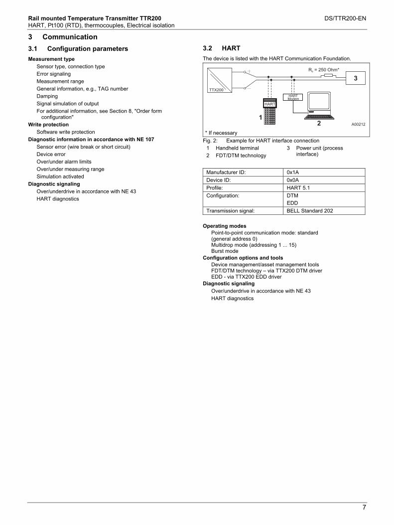
Rail mounted Temperature Transmitter TTR200 DS/TTR200-EN HART, Pt100 (RTD), thermocouples, Electrical isolation
7
Kommunikation
3 Communication Change from one to two columns
3.1 Configuration parameters
Measurement type Sensor type, connection type Error signaling Measurement range General information, e.g., TAG number Damping Signal simulation of output For additional information, see Section 8, "Order form
configuration" Write protection
Software write protection Diagnostic information in accordance with NE 107
Sensor error (wire break or short circuit) Device error Over/under alarm limits Over/under measuring range Simulation activated
Diagnostic signaling Over/underdrive in accordance with NE 43 HART diagnostics
3.2 HART
The device is listed with the HART Communication Foundation.
A00212
HART
21
3
HARTModem
R = 250 Ohm*b
TTX200
* If necessary Fig. 2: Example for HART interface connection
1 Handheld terminal 2 FDT/DTM technology
3 Power unit (process interface)
Manufacturer ID: 0x1A Device ID: 0x0A Profile: HART 5.1 Configuration: DTM
EDD Transmission signal: BELL Standard 202
Operating modes
Point-to-point communication mode: standard (general address 0) Multidrop mode (addressing 1 ... 15) Burst mode
Configuration options and tools Device management/asset management tools FDT/DTM technology – via TTX200 DTM driver EDD - via TTX200 EDD driver
Diagnostic signaling Over/underdrive in accordance with NE 43 HART diagnostics
Change from one to two columns

Rail mounted Temperature Transmitter TTR200 DS/TTR200-EN HART, Pt100 (RTD), thermocouples, Electrical isolation
8
4 Electrical connections Fehler! Verweisquelle konnte nicht gefunden werden.
A00203
12 ... 30 / 42 V DC
+ -11
4 ... 20 mA
TT
R200
+ 11
PWR
ERR
OFF ON
12
-
1 2 3
4 5 6
A
4
2 2 2
1 1 1 1 1 1
4
3 3 3 3 3 3
2
1 2 3 4 5 6
+
-
7
2
3
+
-
8 9
2
3
Fig. 3 1 Potentiometer, four-wire circuit 2 Potentiometer, three-wire circuit 3 Potentiometer, two-wire circuit
4 RTD, four-wire circuit 5 RTD, three-wire circuit 6 RTD, two-wire circuit
7 Voltage measurement 8 Thermocouple 9 Terminal 11: Measurement of 4 … 20 mA output
current without opening / interrupting the current loop
A: no function
• PWR / green LED: Supply voltage display • ERR / red LED: sensor, sensor lead & unit fault signaling • DIP switch 1: on -> Hardware write protection is enabled • DIP switch 2: no function
5 Dimensions
TT
R2
00
+ 11
PWR
ERR
12
-
1 2 3
4 5 6
10
8(4
.25
)
17,5 (0.69)
114 (4.49)
99
(3.9
)
35
(1.3
8)
A00204
OFF ON
Fig. 4: Dimensions in mm (inch)

Rail mounted Temperature Transmitter TTR200 DS/TTR200-EN HART, Pt100 (RTD), thermocouples, Electrical isolation
9
Bestellangaben
6 Ordering information
Main order number
Add. order no.
Version number 1 - 6 7 8 9 10 11 XX
TTR200 rail-mounted temperature transmitter, HART, Pt100 (RTD), thermocouples, electrical isolation TTR200 X X X X X
XX
Explosion protection Without explosion protection Y 0
ATEX intrinsic safety type of protection: Zone 0: II 1 G Ex ia IIC T6, zone 1 (0): II 2 (1) G Ex [ia] ib IIC T6, Zone 1 (20): II 2 G (1D) Ex [iaD] ib IIC T6
E 1
ATEX non-sparking type of protection: Zone 2: II 3 G Ex nA II T6
E 2
IECEx intrinsic safety type of protection: Zone 0: II 1 G Ex ia IIC T6, Zone 1 (0): II 2 (1) G Ex [ia] ib IIC T6, Zone 1 (20): II 2 G (1D) Ex [iaD] ib IIC T6
H 1
FM Intrinsic safety (IS): Class I, Div. 1+2, Groups A, B, C, D, Class I, Zone 0, AEx ia IIC T6, Non-incendive (NI): Class I, Div. 2, Groups A, B, C, D
L 6
CSA Intrinsic safety (IS): Class I, Div. 1+2, Groups A, B, C, D, Non-incendive (NI): Class I, Div. 2, Groups A, B, C, D
R 6
Kazakhstan - metrological approval G 3 Kazakhstan - metrological approval and GOST Ex i G 4 Ukraine - metrological approval G 5 Ukraine - metrological approval and GOST Ex i G 6 Belarus - metrological approval M 5 Belarus - metrological approval and GOST Ex i M 6
Communication protocol HART H
Configuration Standard configuration B SCustomer-specific configuration with report, no spec. user characteristics 1) B F
Calibration certificates 5-point factory calibration certificate EM Acceptance test certificate 3.1 to EN 10204 for 5-point calibration EP
Certificates SIL2 declaration of conformity CS Certificate of compliance 2.1 to EN 10204 for order conformity C4 Acceptance test certificate 3.1 to EN 10204 for visual and functional checks C6
Customer-specific designs (Please provide) Z9
Language of documentation German M1 English M5 Western Europe/Scandinavia language package (languages: DE, EN, DA, ES, FR, IT, NL, PT, FI, SV) MW Eastern Europe language package (languages: DE, EL, CS, ET, LV, LT, HU, PL, SK, SL, RO, BG) ME
1) E.g., customer-specific measuring range, TAG no.
6.1 Documentation available for ordering
Description Order number TTR200 documentation on CD-ROM 3KXT241001R0800 TTR200 commissioning instructions, English 3KXT241001R4401 TTR200 commissioning instructions, German 3KXT241001R4403 TTR200 commissioning instructions, Western Europe / Scandinavia language package 3KXT241001R4493 TTR200 commissioning instructions, Eastern Europe language package 3KXT241001R4494

Rail mounted Temperature Transmitter TTR200 DS/TTR200-EN HART, Pt100 (RTD), thermocouples, Electrical isolation
10
7 Ex relevant specifications Change from one to two columns
The TTR200 complies with the requirements of ATEX Directive 94/9/EC.
7.1 TTR200-E1, Intrinsic Safety ATEX
Explosion protection Approved for use in Zone 0 and 1
Designation II 1G Ex ia IIC T6 (Zone 0) II 2(1)G Ex [ia] ib IIC T6 (Zone 1 [0]) II 2G(1D) Ex [iaD] ib IIC T6 (Zone 1 [20])
EC type-examination test certificate PTB 05 ATEX 2017 X
7.2 TTR200-H1, Intrinsic Safety IECEx
Designation Ex ia IIC T6 Ex [ia] ib IIC T6 Ex [iaD] ib IIC T6
IECEx certificate of conformity IECEx PTB 09.0014X
7.3 Safety specifications for Intrinsic Safety ATEX / IECEx
Temperature table Permissible ambient temperature range Temperature
class Device category 1 use
Device category 2 use
T6 -50 … 44 °C (-58 ... 111.2 °F)
-50 … 56 °C (-58 ... 132.8 °F)
T5 -50 … 56 °C (-58 ... 132.8 °F)
-50 … 71 °C (-58 ... 159.8 °F)
T4, T3, T2, T1 -50 … 60 °C (-58 ... 140.0 °F)
-50 … 85 °C (-58 ... 185.0 °F)
hallo
Type of protection intrinsic safety Ex ia IIC (Part 1) Supply circuit Max. voltage Ui = 30 V Short circuit current Ii = 130 mA Max. power Pi = 0.8 W Internal inductance Li = 0.5 mH Internal capacitance Ci = 5 nF
Type of protection intrinsic safety Ex ia IIC (Part 2); thermocouples, voltages Measurement
current circuit: resistance thermometers, resistors
Measurement current circuit: thermocouples, voltages
Max. voltage Uo = 6.5 V Uo = 1.2 V Short circuit current Io = 25 mA Io = 50 mA Max. power Po = 38 mW Po = 60 mW Internal inductance Li = 0 mH Li = 0 mH Internal capacitance Ci = 49 nF Ci = 49 nF Maximum permissible external inductance
Lo = 5 mH Lo = 5 mH
Maximum permissible external capacitance
Co = 1.55 µF Co = 1.05 µF
7.4 TTR200-E2, Non-Sparking ATEX
Explosion protection Approved for use in Zone 2
Designation II 3 G Ex nA II T6
ABB manufacturer's declaration in accordance with ATEX Directive Temperature table
Temperature class
Device category 3 use
T6 -50 … 56 °C (-58 ... 132,8 °F) T5 -50 … 71 °C (-58 ... 159,8 °F) T4 -50 … 85 °C (-58 ... 185,0 °F)
7.5 TTR200-L6, intrinsically safe FM
Class I, Div. 1 + 2, Groups A, B, C, D Class I, Zone 0, AEx ia IIC T6 Control drawing: TTR200-L6H (I.S.)
7.6 TTR200-L6, non-incendive FM
Class I, Div. 2, Groups A, B, C, D Control drawing: TTR200-L6H (N.I.)
7.7 TTR200-R6, intrinsically safe CSA
Class I, Div. 1 + 2, Groups A, B, C, D Class I, Zone 0, Ex ia Group IIC T6 Control drawing: TTR200-R6H (I.S.)
7.8 TTR200-R6, non-incendive CSA
Class I, Div. 2, Groups A, B, C, D Control drawing: TTR200-R6H (N.I.)
Change from one to two columns
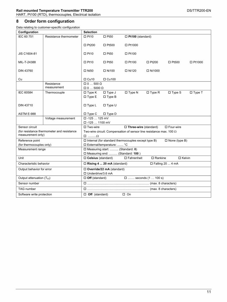
Rail mounted Temperature Transmitter TTR200 DS/TTR200-EN HART, Pt100 (RTD), thermocouples, Electrical isolation
11
8 Order form configuration
Data relating to customer-specific configuration
Configuration Selection IEC 60 751 JIS C1604-81 MIL-T-24388 DIN 43760 Cu
Resistance thermometer Pt10 Pt50 Pt100 (standard)
Pt200 Pt500 Pt1000
Pt10 Pt50 Pt100
Pt10 Pt50 Pt100 Pt200 Pt500 Pt1000
Ni50 Ni100 Ni120 Ni1000
Cu10 Cu100 Resistance
measurement 0 … 500 Ω 0 … 5000 Ω
IEC 60584 DIN 43710 ASTM E-988
Thermocouple
Type K Type J Type N Type R Type S Type T Type E Type B
Type L Type U
Type C Type D
Voltage measurement -125 … 125 mV -125 … 1100 mV
Sensor circuit (for resistance thermometer and resistance measurement only)
Two-wire Three-wire (standard) Four-wire Two-wire circuit: Compensation of sensor line resistance max. 100 Ω
..........Ω Reference point (for thermocouples only)
Internal (for standard thermocouples except type B) None (type B) External/temperature: ....... °C
Measurement range Measuring start: .......... (Standard: 0) Measuring end: .......... (Standard: 100 )
Unit Celsius (standard) Fahrenheit Rankine Kelvin
Characteristic behavior Rising 4 ... 20 mA (standard) Falling 20 ... 4 mA
Output behavior for error Override/22 mA (standard) Underdrive/3.6 mA
Output attenuation (T63) Off (standard) ........ seconds (1 … 100 s)
Sensor number ......................................................................... (max. 8 characters)
TAG number ......................................................................... (max. 8 characters)
Software write protection Off (standard) On

Contact us
DS
/TTR
200-
ENR
ev.B
12.2
010
|3K
XT24
1001
R10
01ABB Ltd. Salterbeck Trading Estate Workington, Cumbria CA14 5DS UK Phone: +44 (0)1946 830 611 Fax: +44 (0)1946 832 661 ABB Inc. 125 E. County Line Road Warminster PA 18974 USA Phone: +1 215 674 6000 Fax: +1 215 674 7183 ABB Automation Products GmbH Schillerstr. 72 32425 Minden Germany Phone: +49 551 905-534 Fax: +49 551 905-555 www.abb.com
Note We reserve the right to make technical changes or modify the contents of this document without prior notice. With regard to purchase orders, the agreed particulars shall prevail. ABB does not accept any responsibility whatsoever for potential errors or possible lack of information in this document. We reserve all rights in this document and in the subject matter and illustrations contained therein. Any reproduction, disclosure to third parties or utilization of its contents - in whole or in parts – is forbidden without prior written consent of ABB. Copyright© 2010 ABB All rights reserved

PageGeneral Information . . . . . . . . . . . . . . . . . . . . . . . . . . . . . . . . . . . . . . . . . . . . . . . . . . . . . . . . 2
Delivery Program . . . . . . . . . . . . . . . . . . . . . . . . . . . . . . . . . . . . . . . . . . . . . . . . . . . . . . . . . . 2Standard types . . . . . . . . . . . . . . . . . . . . . . . . . . . . . . . . . . . . . . . . . . . . . . . . . . . . . . . . . . . . . 2Special manufactures . . . . . . . . . . . . . . . . . . . . . . . . . . . . . . . . . . . . . . . . . . . . . . . . . . . . . . . . . . 2Production lengths . . . . . . . . . . . . . . . . . . . . . . . . . . . . . . . . . . . . . . . . . . . . . . . . . . . . . . . . . . . 2Minimum order value . . . . . . . . . . . . . . . . . . . . . . . . . . . . . . . . . . . . . . . . . . . . . . . . . . . . . . . . . . 2
Technical Data . . . . . . . . . . . . . . . . . . . . . . . . . . . . . . . . . . . . . . . . . . . . . . . . . . . . . . . . . . . . 3Insulation ceramic . . . . . . . . . . . . . . . . . . . . . . . . . . . . . . . . . . . . . . . . . . . . . . . . . . . . . . . . . . . . 3Insulation resistance . . . . . . . . . . . . . . . . . . . . . . . . . . . . . . . . . . . . . . . . . . . . . . . . . . . . . . . . . . . 3Loop resistance (resistance of inner conductors) . . . . . . . . . . . . . . . . . . . . . . . . . . . . . . . . . . . . . . . . . . . . 3Processing . . . . . . . . . . . . . . . . . . . . . . . . . . . . . . . . . . . . . . . . . . . . . . . . . . . . . . . . . . . . . . . . 3Dimensions . . . . . . . . . . . . . . . . . . . . . . . . . . . . . . . . . . . . . . . . . . . . . . . . . . . . . . . . . . . . . . . 4Tolerances and temperature ranges . . . . . . . . . . . . . . . . . . . . . . . . . . . . . . . . . . . . . . . . . . . . . . . . . . 4
The Short-range Ordered State in NiCr-Ni Thermocouples (Type K) . . . . . . . . . . . . . . . . . . . . . . . . . 5
Standard Sheath Materials . . . . . . . . . . . . . . . . . . . . . . . . . . . . . . . . . . . . . . . . . . . . . . . . . . . . 7
Mineral Insulated Thermocouple Cables . . . . . . . . . . . . . . . . . . . . . . . . . . . . . . . . . . . . . . . . . . . 9
Mineral Insulated Cables . . . . . . . . . . . . . . . . . . . . . . . . . . . . . . . . . . . . . . . . . . . . . . . . . . . . 11
Mineral Insulated Cables with Precious Metal Thermocouples . . . . . . . . . . . . . . . . . . . . . . . . . . . 12Application . . . . . . . . . . . . . . . . . . . . . . . . . . . . . . . . . . . . . . . . . . . . . . . . . . . . . . . . . . . . . . . 12Standard types . . . . . . . . . . . . . . . . . . . . . . . . . . . . . . . . . . . . . . . . . . . . . . . . . . . . . . . . . . . . 12Special manufacture . . . . . . . . . . . . . . . . . . . . . . . . . . . . . . . . . . . . . . . . . . . . . . . . . . . . . . . . . 12Maximum production lengths . . . . . . . . . . . . . . . . . . . . . . . . . . . . . . . . . . . . . . . . . . . . . . . . . . . . . 12
SensyHeat – Heaters . . . . . . . . . . . . . . . . . . . . . . . . . . . . . . . . . . . . . . . . . . . . . . . . . . . . . . 13
SensyMIC – Mineral Insulated Cables
SensyHeat – Heaters
Cables Catalog
10-7.10 EN
05.99 1

General Information
Mineral insulated cables have an outer sheath of metal with 2 to8 inner conductors. The insulation material is made from a highlycompressed metal-oxide powder (preferably MgO or Al2O3).
Mineral insulated thermocouple cables have inner conductors ofthermocouple base material. Mineral insulated cables for RTDshave inner conductors of copper, copper-nickel alloys, nickel,nickel-chromium or nickel-plated copper.
Mineral insulated cables are designed for high-temperature appli-cations and are used wherever there are particularly strict require-ments with regard to mechanical, chemical and electrical stability.
On account of their good flexibility, the use of mineral insulatedcables is preferred in areas where mounting is difficult and wherea high degree of flexibility is required (for example, laboratories orpilot manufacturing plants).The minimum bending radius is 3 timesthe outer diameter of the mineral insulated cable.
Innovations in technology and manufacturing have made it pos-sible for these cables to be used increasingly frequently as amaterial in the manufacture of standardized thermocouples andRTDs, in particular in industrial measuring and control technologyand in automotive sensor technology.
Delivery Program
SENSYCON offers a wide range of mineral insulated cables forthe production of mineral insulated thermocouples and mineralinsulated RTDs.
All standardized thermocouples type K, J, L, T, U, E and N and theprecious metal thermocouples type R, S and B are available asmineral insulated thermocouple cables. Various mineral insulatedcables with copper, copper-nickel, nickel and nickel-chromiuminner conductors are also available ex stock.
However, not all combinations of sheath material and thermo-couple are possible as, for example, for high-temperature-resis-tant sheath materials some of the necessary heat treatmentsconsiderably exceed the maximum permissible temperatures forthe leads.
The following steels and alloys are available as sheath materials:
1.4301 complies with AISI 304 1.4306 complies with AISI 304 L 1.4404 complies with AISI 316 L
1.4541 complies with AISI 321 1.4571 complies with AISI 316 TI 1.4749 complies with AISI 446
1.4841 complies with AISI 314 1.4845 complies with AISI 310 S 1.4876 complies with INCOLOY 800
2.4816 complies with INCONEL 600 2.4851 complies with INCONEL 601 2.4951 complies with Nimonic 75 Platinum 10 % Rhodium
Special Materials
Special manufactures can be produced for special applications,for example using special materials and insulation materials ordesigned within specific tolerances.
Standard Types
The catalog numbers printed in bold are standard types and canbe delivered at short notice.
Special Manufactures
The catalog numbers printed normally are special manufacturesand are not available ex stock. However, they can be producedwith a minimum order quantity (one production length) and aminimum production time.
Production Lengths
The production lengths of mineral insulated cables depend on thelength of the available tubes.
The following lengths can be delivered:
Outer ∅ Production length (mm) (approx.)
0.5 500 m 1.0 600/1.000 m 1.5 310/1.500 m 1.6 250/1.300 m 2.0 700 m
3.0 420/530 m 3.2 365/460 m 4.5 180 m 4.8 160 m 6.0 105 m
6.4 88 m 8.0 58 m 10.0 35 m
Minimum Order Value
The minimum order value is DEM 300.00/Euro 150.00.For order values less than DEM 300.00/Euro 150.00 and quantitiesless than one production length, a surcharge of 25% is added.
SensyMIC – Mineral Insulated Cables
Cables Catalog
10-7.10 EN
2 05.99

Technical Data
Insulation Ceramics
SENSYCON supplies MgO as the standard insulator with a purityof ≥ 96 % as well as MgO with a purity of ≥ 99.4 % and Al2O3.
Insulation Resistance
The insulation resistance depends on the purity of the insulationceramics used as well as the manufacturing process and thehumidity content of the insulation. The cables are supplied fullydried with ends that are hermetically sealed. The following valuesof the insulation resistance are guaranteed upon delivery (seetable 1).
The insulation resistance also depends on the length of the cable.Therefore, it is listed as a length-related resistance in Ω × m.Example: L = 100 m; Ris = 10 MΩ
Ris = 10 MΩ × 100 m = 1000 MΩ × m
The minimum value at room temperature is 1000 MΩ × m acc. to DIN EN 61515.
DIN EN 61515 provides for the minimum requirements stated intable 1.
Test voltagesOuter diameter ≤ 1.5 mm: 75 V ± 25 V DCOuter diameter > 1.5 mm: 500 V ± 50 V DC
The minimum values at higher temperatures can be confirmed onrequest.
Loop Resistance (resistance of inner conductors)
In order to assess measuring errors, the loop resistance is animportant parameter in addition to the insulation resistance. Thelower the loop resistance, the lower its influence on the measuringaccuracy. The maximum loop resistance of the various MI cables is shownin table 2.
Processing
It is absolutely necessary that the cable is sufficiently dried afterthe seal is opened or after the mineral insulated cable is cut intothe lengths required. Immediately after drying, the cable must besealed. The cable must not be stored with open ends.
SensyMIC – Mineral Insulated Cables
Table 2: Loop Resistance for 1 Thermocouple at 20 °C in Ω/m (approx. values)
Thermocouple(TP = Thermocouple)
Outer ∅ mm
0.5 1.0 1.5 1.6 2.0 3.0 3.2 4.5 4.8 6.0 6.4 8.0
1 TPNiCr-Ni
150 32/44 15/19 13/18 10.5 6.4 5.3 2.8 2.5 1.6 1.4 0.9
2 TPNiCr-Ni
6.2 3.1 1.6 0.8
1 TPFe-CuNi
130 34 15 13 8.6 4.2 3.0 1.7 1.4 1.0 0.7 0.5
2 TPFe-CuNi
3.7 1.8 1.0 0.5
Table 1: Insulation Resistance Values at Ambient and Elevated Temperatures(The values are intended to specify the minimum requirements for operations but not for manufacturer’s quality control tests)
Minimum immersed length attest temperature
m
Test temperature
°C
Minimum insulation resistance
MΩm
Ambient temperature 1 20 ± 15 1000
Elevated temperaturetype J, E, K and N
0.5 500 ± 15 5
Elevated temperatureType T
0.5 300 ± 10 500
Note – The insulant of a mineral insulated thermocouple cable or thermocouple has a finite conductivity and therefore the insulationresistance decreases as the length of the cable or thermocouple increases. The conductance of a specific cable or thermocouple istherefore expressed in Sm-1 (equivalent to Ω-1 ⋅ m-1) and hence the minimum specified insulation resistance is expressed in Ωm or MΩmfor cables or thermocouples longer than 1 m. For shorter lengths, it is expressed in MΩ.
Cables Catalog
10-7.10 EN
05.99 3

SensyMIC – Mineral Insulated Cables
Dimensions
The following table shows the tolerances of the outer diameter, minimum wall thickness, minimum conductor diameter and thickness ofthe insulation according to DIN EN 61515.
D
C
S
I
I
I
D = Outer diameterC = Conductor diameterS = Wall thicknessI = Insulation thickness
Outer diameter of the cable (D)Nominal value
± tolerance, mm
Minimum wall thickness (S),
mm
Minimum diameterof the inner
conductor (C),mm
Minimum thickness(I) of the
insulation, mm
0.5 ± 0.025 1.0 ± 0.025 1.5 ± 0.025 1.6 ± 0.025 2.0 ± 0.025
3.0 ± 0.030 3.2 ± 0.030 4.0 ± 0.045 4.5 ± 0.045 4.8 ± 0.045
6.0 ± 0.060 6.4 ± 0.060 8.0 ± 0.08010.0 ± 0.100
0.050.100.150.160.20
0.300.320.400.450.48
0.600.640.801.00
0.080.150.230.240.30
0.450.480.600.680.72
0.900.961.201.50
0.040.080.120.130.16
0.240.260.320.360.38
0.480.510.640.80
Excerpt from the Tolerances and Temperature Ranges for Thermocouples
Thermocouple Type Temperature Range °C Tolerance
Thermocouples according to DIN EN 60584
Class 1
E - 40 to + 800 ± 1.5 °C or ± 0.004 × t
J - 40 to + 750 ± 1.5 °C or ± 0.004 × t
K/N - 40 to + 1000 ± 1.5 °C or ± 0.004 × t
Class 2
E - 40 to + 900 ± 2.5 °C or ± 0.0075 × t
J - 40 to + 750 ± 2.5 °C or ± 0.0075 × t
K/N - 40 to + 1200 ± 2.5 °C or ± 0.0075 × t
T - 40 to + 350 ± 1.0 °C or ± 0.0075 × t
R/S ± 0 to + 1600 ± 1.5 °C or ± 0.0025 × t
Class 3
B + 600 to + 1700 ± 4.0 °C or ± 0.005 × t
Thermocouples according to DIN 43 710
U - 200 to + 600 from 0 to + 400 °C ± 3 °C from + 400 to + 600 °C ± 0.0075 × t
L - 200 to + 900 from 0 to + 400 °C ± 3 °C from + 400 to + 900 °C ± 0.0075 × t
Cables Catalog
10-7.10 EN
4 05.99

The short-range ordered state inNiCr-Ni thermocouples (type K)
Type K thermocouples are the most widely used thermocouplesin process measuring technology, and not only there.Why?
– Their wide temperature range from – 200 to 1200 °C– Their excellent long-term stability under oxidizing conditions– Their high sensitivity of 40 µV/°C– Their superior suitability within mineral insulated thermo-
couples– Their moderate price compared to precious metals
make these thermocouples an optimal solution both technicallyand financially.
From time to time arguments come up denying the suitability ofthis thermocouple type for the accuracy required in industrialmeasuring and control technology because these alloys are sub-ject to the short-range ordered state.
What is the short-range ordered state?
The short-range ordered state is a phenomenon which occurs withnickel-chromium alloys and predominantly affects their thermo-electric properties. It is a magnetic ordering state of the individualelements of the matrix.
A distinction is made between– the ordered state, the so-called K state, and– the disordered state, which will be called U state.
One can imagine that in the K state the matrix elements stand inrank and file, whereas in the U state there is no order to theirpositions.These states can be produced by certain temperature treatmentsand can easily be reversed.
In addition, transition states between the above states often occur.
What is the effect of the ordering states?
The electromotive force (e.m.f.) of a nickel-chromium wire in theK state may differ from an identical wire in the U state by theequivalent of 2 to 3 °C depending on the temperature and testmethod. In the transition states this value is lower.
How are the ordering states created?
Above 600 °C nickel-chromium alloys are always in the disor-dered or U state. After reaching this temperature the U state isformed very quickly.
If the alloy is cooled rapidly (in a few minutes) to room temperature,the U state will be kept as long as the temperature of the alloy isnot raised above room temperature. The U state is "frozen in".
If the alloy is cooled slowly (in a few hours) to room temperature,a transition state between K and U generally appears.
If the alloy is kept for an extended period (one or two days) withina temperature range of 250 to 500 °C, the K state will be formedand sustained until the alloy is heated to 600 °C or above again.
What heat treatment is applied to mineral insulated thermo-couples before delivery?
All manufacturers apply annealing after the last drawing step toreduce any hardening of the sheath and wires caused by plasticdeformation, i.e. to make the mineral insulated thermocouple softand thus flexible and to reverse major changes in e.m.f.
This annealing is applied at temperatures above 600 °C, i.e. thewires are in the U state.
After annealing, the cables are usually cooled as quickly aspossible in order to avoid precipitation processes, for example insheaths of austenitic stainless steels (1.4571 or similar), whichwould impair the weld ability. This results in a more or lessundefined transition state between K and U in the wires; it ispossible to achieve such rapid cooling that the U state is frozen inin small cable cross-sections only in some continuous coolingplants.
What is the behaviour of thermocouples in the differentmodes of delivery?
The majority of thermocouples are installed so that the measuringjunction is at an elevated temperature and so that the temperaturealong the length of the thermocouple decreases with variousslopes down to room temperature.
With a perfectly homogeneous thermocouple, i.e. the individualwires are completely identical over their whole length and do nothave any local impurities or irregularities in their matrix, the e.m.f.will depend exclusively on the difference between the measuringjunction and the reference junction.
However, if the thermocouple is not homogeneous, deviationsfrom the original e.m.f. will occur, which depend on the nature andamount of the inhomogeneity and the temperature profile alongthe thermocouple.
Every thermocouple type K, regardless of the mode of delivery,will change after installation and when first used because it isalways led through a temperature range in which the K state isformed after an extended period of time.
It is important to consider that the K state will also be formed attemperatures slightly below 250 °C, but much more slowly, it maytake weeks.
SensyMIC – Mineral Insulated Cables
Cables Catalog
10-7.10 EN
05.99 5
SensyMIC – Mineral Insulated Cables
What happens when first heated to 600 °C and above?
The following is based on a "regular" installation of the thermo-couple as it is common in process control:The insertion length of the thermocouple is fixed and the operatingtemperature does not vary significantly.
1. Delivery in the U stateAt the measuring junction, nothing happens because the U stateis already present. In the so-called temperature gradient, i.e.where the temperature decreases towards the end of the thermo-couple, the K state will gradually be formed over weeks (seeabove). During this period, the deviation from true e.m.f. changescontinuously. Reliable temperature measurement and control arenot possible. At the cold end of the thermocouple, a local transitionfrom the K state to the U state appears, another inhomogeneitywith additional influence on the e.m.f.
2. Delivery in the transition stateAt the measuring junction, the U state is formed relatively quickly.In the temperature gradient a creeping transition into the K stateoccurs and at the cold end a local transition from the K state to thetransition state is formed as an additional source of errors.
3. Delivery in the K stateAt the measuring junction the U state develops very quickly. In thetemperature gradient and at the cold end, nothing happens as theK state is already present everywhere here, i.e. this mode ofdelivery offers immediate stable and reliable temperature indica-tion.
How are mineral insulated thermocouples tested?
For a reliable e.m.f. test, the samples are transferred to the K state.If this is not done, the effects shown above for the first two deliverymodes occur during calibration.
When can reliable temperature measurement be expected?
Reliable temperature measurement which also corresponds to thee.m.f. determined in the test can only be expected if the mineralinsulated thermocouples are delivered in the stable K state. There-fore, mineral insulated thermocouples should only be delivered inthe stable K state.
SENSYCON is the only manufacturer to apply expensive secondfinal annealing which ensures that all cables are delivered in thestable K state.
Cables Catalog
10-7.10 EN
6 05.99
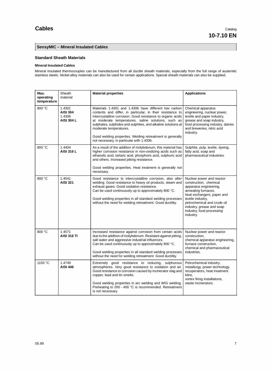
SensyMIC – Mineral Insulated Cables
Max.operatingtemperature
Sheathmaterial
Material properties Applications
800 °C 1.4301 AISI 3041.4306 AISI 304 L
Materials 1.4301 and 1.4306 have different low carboncontents and differ, in particular, in their resistance tointercrystalline corrosion. Good resistance to organic acidsat moderate temperatures, saline solutions, such assulphates, sulphides and sulphites, and alkaline solutions atmoderate temperatures.
Good welding properties. Welding retreatment is generallynot necessary, in particular with 1.4306.
Chemical apparatusengineering, nuclear power,textile and paper industry,grease and soap industry, food processing industry, dairiesand breweries, nitric acidindustry.
800 °C 1.4404 AISI 316 L
As a result of the addition of molybdenum, this material hashigher corrosion resistance in non-oxidizing acids such asethanolic acid, tartaric acid, phosphoric acid, sulphuric acidand others. Increased pitting resistance.
Good welding properties. Heat treatment is generally notnecessary.
Sulphite, pulp, textile, dyeing, fatty acid, soap andpharmaceutical industries.
800 °C 1.4541AISI 321
Good resistance to intercrystalline corrosion, also afterwelding. Good resistance to heavy oil products, steam andexhaust gases. Good oxidation resistance.Can be used continuously up to approximately 800 °C.
Good welding properties in all standard welding processeswithout the need for welding retreatment. Good ductility.
Nuclear power and reactorconstruction, chemicalapparatus engineering,annealing furnaces, heat exchangers, paper andtextile industry,petrochemical and crude oilindustry, grease and soapindustry, food processingindustry.
800 °C 1.4571AISI 316 TI
Increased resistance against corrosion from certain acidsdue to the addition of molybdenum. Resistant against pitting,salt water and aggressive industrial influences. Can be used continuously up to approximately 800 °C.
Good welding properties in all standard welding processeswithout the need for welding retreatment. Good ductility.
Nuclear power and reactorconstruction, chemical apparatus engineering, furnace construction, chemical and pharmaceuticalindustries.
1150 °C 1.4749AISI 446
Extremely good resistance to reducing, sulphurousatmospheres. Very good resistance to oxidation and air.Good resistance to corrosion caused by incinerator slag andcopper, lead and tin smelts.
Good welding properties in arc welding and WIG welding.Preheating to 200 - 400 °C is recommended. Retreatmentis not necessary.
Petrochemical industry,metallurgy, power technology,recuperators, heat treatmentkilns, vortex firing installations,waste incinerators.
Standard Sheath Materials
Mineral Insulated Cables
Mineral insulated thermocouples can be manufactured from all ductile sheath materials, especially from the full range of austeniticstainless steels. Nickel-alloy materials can also be used for certain applications. Special sheath materials can also be supplied.
Cables Catalog
10-7.10 EN
05.99 7
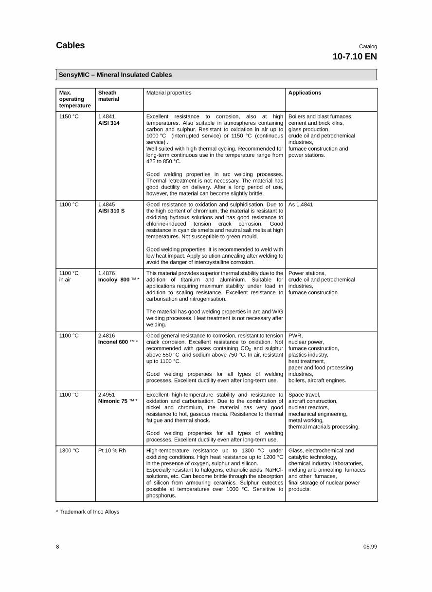
SensyMIC – Mineral Insulated Cables
Max.operatingtemperature
Sheath material
Material properties Applications
1150 °C 1.4841AISI 314
Excellent resistance to corrosion, also at hightemperatures. Also suitable in atmospheres containingcarbon and sulphur. Resistant to oxidation in air up to1000 °C (interrupted service) or 1150 °C (continuousservice) .Well suited with high thermal cycling. Recommended forlong-term continuous use in the temperature range from425 to 850 °C.
Good welding properties in arc welding processes.Thermal retreatment is not necessary. The material hasgood ductility on delivery. After a long period of use,however, the material can become slightly brittle.
Boilers and blast furnaces, cement and brick kilns,glass production,crude oil and petrochemicalindustries,furnace construction andpower stations.
1100 °C 1.4845AISI 310 S
Good resistance to oxidation and sulphidisation. Due tothe high content of chromium, the material is resistant tooxidizing hydrous solutions and has good resistance tochlorine-induced tension crack corrosion. Goodresistance in cyanide smelts and neutral salt melts at hightemperatures. Not susceptible to green mould.
Good welding properties. It is recommended to weld withlow heat impact. Apply solution annealing after welding toavoid the danger of intercrystalline corrosion.
As 1.4841
1100 °Cin air
1.4876Incoloy 800 ™ *
This material provides superior thermal stability due to theaddition of titanium and aluminium. Suitable forapplications requiring maximum stability under load inaddition to scaling resistance. Excellent resistance tocarburisation and nitrogenisation.
The material has good welding properties in arc and WIGwelding processes. Heat treatment is not necessary afterwelding.
Power stations,crude oil and petrochemical industries,furnace construction.
1100 °C 2.4816Inconel 600 ™ *
Good general resistance to corrosion, resistant to tensioncrack corrosion. Excellent resistance to oxidation. Notrecommended with gases containing CO2 and sulphurabove 550 °C and sodium above 750 °C. In air, resistantup to 1100 °C.
Good welding properties for all types of weldingprocesses. Excellent ductility even after long-term use.
PWR, nuclear power, furnace construction, plastics industry, heat treatment, paper and food processing industries, boilers, aircraft engines.
1100 °C 2.4951Nimonic 75 ™ *
Excellent high-temperature stability and resistance tooxidation and carburisation. Due to the combination ofnickel and chromium, the material has very goodresistance to hot, gaseous media. Resistance to thermalfatigue and thermal shock.
Good welding properties for all types of weldingprocesses. Excellent ductility even after long-term use.
Space travel, aircraft construction, nuclear reactors, mechanical engineering, metal working, thermal materials processing.
1300 °C Pt 10 % Rh High-temperature resistance up to 1300 °C underoxidizing conditions. High heat resistance up to 1200 °Cin the presence of oxygen, sulphur and silicon. Especially resistant to halogens, ethanolic acids, NaHCl-solutions, etc. Can become brittle through the absorptionof silicon from armouring ceramics. Sulphur eutecticspossible at temperatures over 1000 °C. Sensitive tophosphorus.
Glass, electrochemical andcatalytic technology, chemical industry, laboratories,melting and annealing furnacesand other furnaces, final storage of nuclear powerproducts.
* Trademark of Inco Alloys
Cables Catalog
10-7.10 EN
8 05.99
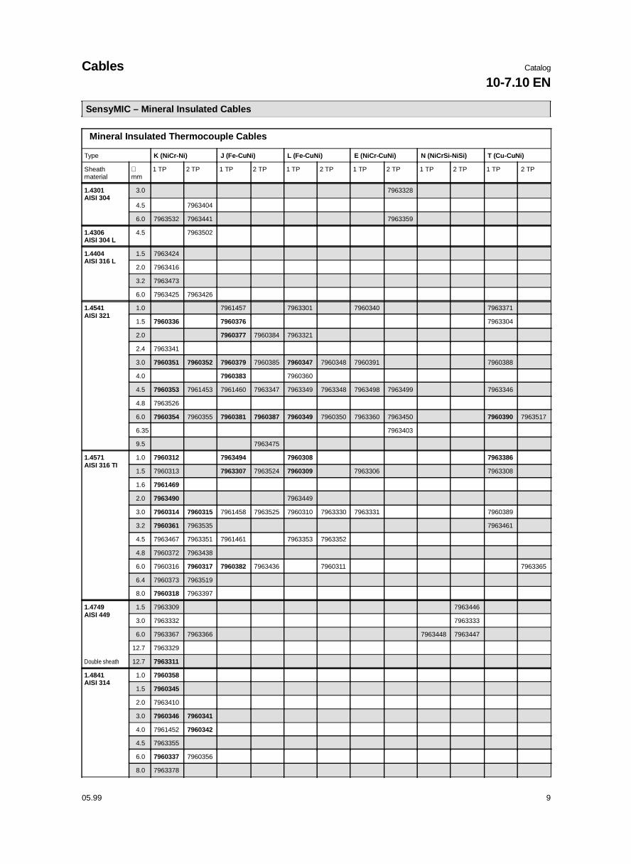
Mineral Insulated Thermocouple Cables
Type K (NiCr-Ni) J (Fe-CuNi) L (Fe-CuNi) E (NiCr-CuNi) N (NiCrSi-NiSi) T (Cu-CuNi)
Sheathmaterial
∅ mm
1 TP 2 TP 1 TP 2 TP 1 TP 2 TP 1 TP 2 TP 1 TP 2 TP 1 TP 2 TP
1.4301AISI 304
3.0 7963328
4.5 7963404
6.0 7963532 7963441 7963359
1.4306AISI 304 L
4.5 7963502
1.4404AISI 316 L
1.5 7963424
2.0 7963416
3.2 7963473
6.0 7963425 7963426
1.4541AISI 321
1.0 7961457 7963301 7960340 7963371
1.5 7960336 7960376 7963304
2.0 7960377 7960384 7963321
2.4 7963341
3.0 7960351 7960352 7960379 7960385 7960347 7960348 7960391 7960388
4.0 7960383 7960360
4.5 7960353 7961453 7961460 7963347 7963349 7963348 7963498 7963499 7963346
4.8 7963526
6.0 7960354 7960355 7960381 7960387 7960349 7960350 7963360 7963450 7960390 7963517
6.35 7963403
9.5 7963475
1.4571AISI 316 TI
1.0 7960312 7963494 7960308 7963386
1.5 7960313 7963307 7963524 7960309 7963306 7963308
1.6 7961469
2.0 7963490 7963449
3.0 7960314 7960315 7961458 7963525 7960310 7963330 7963331 7960389
3.2 7960361 7963535 7963461
4.5 7963467 7963351 7961461 7963353 7963352
4.8 7960372 7963438
6.0 7960316 7960317 7960382 7963436 7960311 7963365
6.4 7960373 7963519
8.0 7960318 7963397
1.4749AISI 449
1.5 7963309 7963446
3.0 7963332 7963333
6.0 7963367 7963366 7963448 7963447
12.7 7963329
Double sheath 12.7 7963311
1.4841AISI 314
1.0 7960358
1.5 7960345
2.0 7963410
3.0 7960346 7960341
4.0 7961452 7960342
4.5 7963355
6.0 7960337 7960356
8.0 7963378
SensyMIC – Mineral Insulated Cables
Cables Catalog
10-7.10 EN
05.99 9

Mineral Insulated Thermocouple Cables
Type K (NiCr-Ni) J (Fe-CuNi) L (Fe-CuNi) E (NiCr-CuNi) N (NiCrSi-NiSi) T (Cu-CuNi)
Sheathmaterial
∅ mm
1 TP 2 TP 1 TP 2 TP 1 TP 2 TP 1 TP 2 TP 1 TP 2 TP 1 TP 2 TP
1.4845AISI 310 S
3.0 7960368
4.5 7960369
6.0 7960370 7960371
1.4876Incoloy 800 ™
1.5 7963310
1.8 7963316
3.0 7960357 7963413
4.5 7963395
6.0 7960344 7963368 7963369
8.0 7963379 7963419
9.5 7963523 7963444
10.0 7963382 7961454
12.0 7963383
1.4893 3.0 7963442
2.4816Inconel 600 ™
0.25 7963538
0.5 7960325
0.8 7963539
1.0 7960326 7963303 7960359 7963302
1.5 7960327 7960362 7960375 7963305 7960319 7963312 7960364
1.6 7960338 7963315
2.0 7960339 7963325 7963417 7963324
2.3 7963396
2.5 7963326
3.0 7960328 7960329 7960378 7961462 7960320 7963340 7963431 7963339 7960365 7963336
3.2 7960343 7963536 7963527
4.5 7960330 7960331 7961459 7963439 7960321 7960322 7960572 7963356
Double sheath 4.5 7963433
4.8 7961455
6.0 7960332 7960333 7960380 7960386 7960323 7960324 7963375 7960586 7960366 7963372
6.4 7960363 7960367
Double sheath 6.5 7963509 7963492
7.8 7963455 7963456 7963377
8.0 7960334 7960335 7963430 7963380 7963381
9.0 7963334
9.5 7963454 7963453
2.4951Nimonic 75 ™
1.8 7963317
3.0 7963342
Double sheath 3.0 7963412
Double sheath 6.0 7963435
8.0 7963489
10.0 7963443
™ Trade mark of Inco Alloys
SensyMIC – Mineral Insulated Cables
Cables Catalog
10-7.10 EN
10 05.99

Mineral Insulated Cables
Con-ductors
Ø mm Material
1.4404 1.4541 1.4571 2.4816
2 x Cu 1.50 7963414
1.60 7963313 7963314
2.00 7963320
3.00 7960400 7961464
4.50 7963496
4.78 7963415 7963521
6.00 7960401 7960395
3 x Cu 1.60 7963459
2.00 7963319
3.00 7963338
4.78 7963471 7961467
4 x Cu 1.00 S 7963506
1.30 S 7963507
2.00 7963318
2.80 7963389
3.00 7960399 7960396 7963337
4.00 7963343 7963344
4.50 7963357 7963350 7960404
4.78 7963460 7961468
4.80 7963387
5.00 7963385 7963358
5.00 S 7963495
6.00 7960402 7960397 7963373
6.00 S 7963364
6.40 7960588
8.00 7963451
6 x Cu 4.50 7963409
4.80 7963388
5.00 7963508 7963502
6.00 7960403 7961465
6.00 S 7963491
8.00 7963362
Mineral Insulated Cables
Con-ductors
Ø mm Material
1.4404 1.4541 1.4571 2.4816
8 x Cu 3.00 7963539
6.00 7963420
3 x CuNi 6.00 7963402
4 x CuNi 6.00 7963280
6 x CuNi 6.00 7963281
2 x Ni 3.00 7963354
3 x Ni 2.40 7963411
3.00 7963501
4.50 7963466
6.00 7963408
4 x Ni 3.20 S 7963398
3.50 S 7963445
4.50 7963695
4.80 S 7963694 7963399
6.00 7963465
6.40 S 7963400
8.00 7963401
6 x Ni 6.00 7963423
2 x NiCr 2.50 7963327
3.00 7961463
6.00 7963361
4 x NiCr 2.00 7963323
3.00 7960392 7963468
4.50 7963345
6.00 7960393 7963469
6.00 S 7961466
6 x NiCr 6.00 7960394 7963470
8.00 7963457
8 x NiCr 6.00 7960398
2 x 2.4816 6.00 7963374
S = Special manufacture
SensyMIC – Mineral Insulated Cables
Cables Catalog
10-7.10 EN
05.99 11

Mineral Insulated Thermocouple Cables with Precious Metal Thermocouples
Precious metal thermocouples are exceptionally suited for high-temperature applications under oxidizing conditions. They are used inchemical plants when absolute resistance to all kinds of acids is required.
SensyMIC – Mineral Insulated Cables
Resistance of Precious Metal Mineral Insulated Thermocouples in different Atmospheres
Sheathmaterial
Thermo-couple
Max. operatingtemperature
Oxygen Nitrogen Hydrogen Carbon Chlorine Sulphur Class oftolerance
2.4816 Type S 1100 °C * good good good good good condi-tional
2
Type R 1100 °C * good good good good good condi-tional
2
Type B 1100 °C * good good good good good condi-tional
3
Pt10%Rh Type S 1300 °C * good good conditional conditional conditional condi-tional
2
Type R 1300 °C * good good conditional conditional conditional condi-tional
2
Type B 1300 °C * good good conditional conditional conditional condi-tional
3
* Because of the drift behaviour at high temperatures, the recommended maximum temperature is 900 °C.
Application
When using precious metal thermocouples, it is necessary to beaware that the insulation resistance of the insulation ceramicsused decreases very much at high temperatures (over 1000 °C).If big lengths of the sheath material are exposed to high tempera-tures, measuring errors can occur as a result of a mean value beingtaken over the installation length.
Standard Type
The standard mineral insulated cables have a 2.4816 sheath withdiameter 1.5 mm and 3.0 mm in type S and diameter 1.6 mm and3.2 mm in type R.
Product nos.S 1.5 2.4816 7960435S 3.0 2.4816 7960436R 1.6 2.4816 7960456R 3.2 2.4816 7960463
Mineral insulated cables with a Pt10%Rh sheath are available intype S with diameter 1.5 mm and 3.0 mm and in type R in 1.6 mmex stock.
Product nos.S 1.5 Pt10%Rh 7960445S 3.0 Pt10%Rh 7960446R 1.6 Pt10%Rh 7960459
Special Manufacture
Special manufactures are always possible in other dimensions onrequest. Sheath materials with other PtRh - alloys can be supplied.
The minimum production length is 1.5 m.The following table provides an overview of the maximum produc-tion lengths of the most popular dimensions.Bigger lengths are possible in special cases on request.
Maximum Production Lengths
Sheath TP ∅ 1.0mm
∅ 1.5mm
∅ 1.6mm
∅ 2.0mm
∅ 3.0mm
∅ 3.2mm
∅ 4.5mm
∅ 4.8mm
∅ 6.0mm
∅ 6.4mm
Pt10%Rh 1 × S 20 m 20 m 18 m 9 m 6 m 5 m 6 m 5 m 3 m
2 × S 20 m 20 m 18 m 9 m 6 m 5 m 6 m 5 m 3 m
1 × R 20 m 20 m 18 m 9 m 6 m 5 m 6 m 5 m 3 m
2 × R 20 m 20 m 18 m 9 m 6 m 5 m 6 m 5 m 3 m
2.4816 1 × S 35 m 310 m 265 m 155 m 90 m 80 m 18 m 7 m 10 m 8.5 m
2 × S 14 m 265 m 155 m 90 m 80 m 18 m 7 m 10 m 8.5 m
1 × R 35 m 14 m 265 m 155 m 90 m 80 m 18 m 7 m 10 m 8.5 m
2 × R 14 m 265 m 155 m 90 m 80 m 18 m 7 m 10 m 8.5 m
Cables Catalog
10-7.10 EN
12 05.99
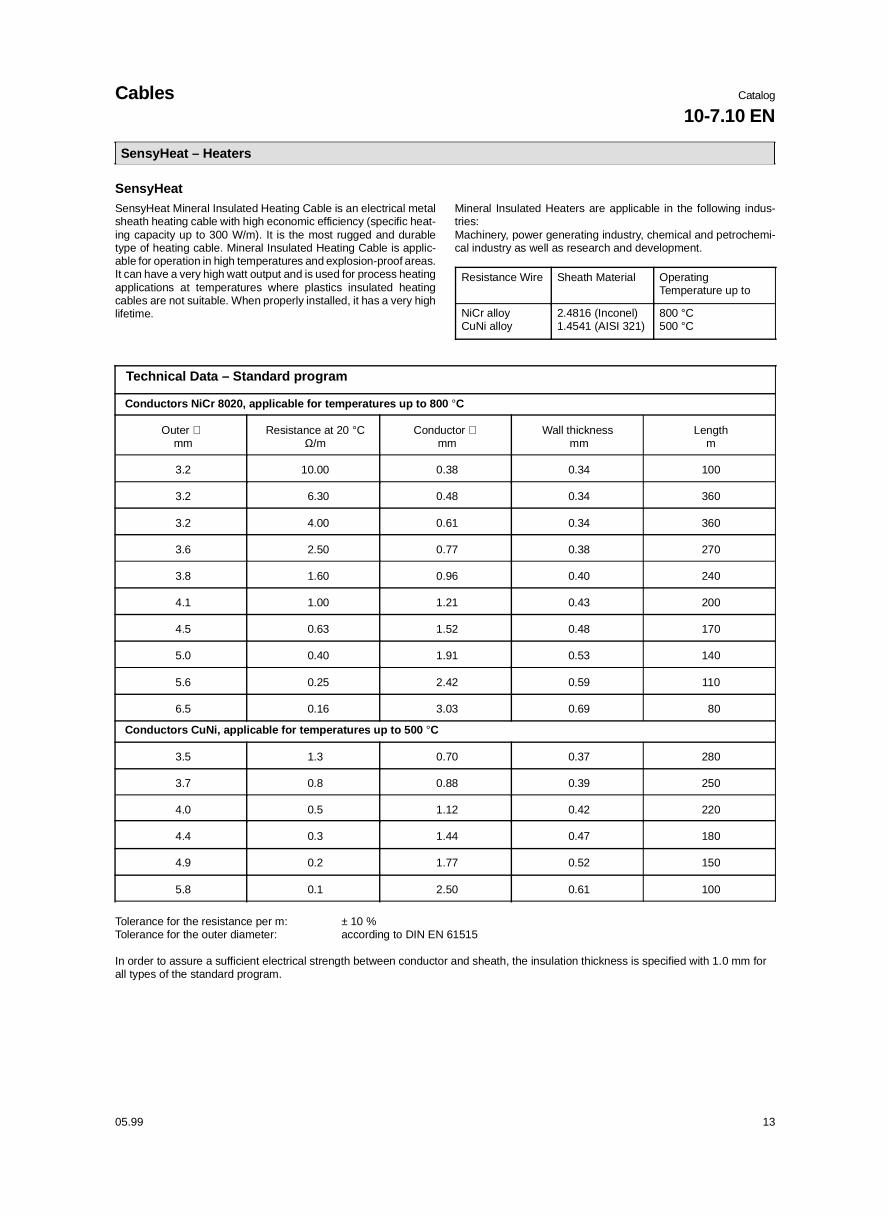
SensyHeat – Heaters
SensyHeat SensyHeat Mineral Insulated Heating Cable is an electrical metalsheath heating cable with high economic efficiency (specific heat-ing capacity up to 300 W/m). It is the most rugged and durabletype of heating cable. Mineral Insulated Heating Cable is applic-able for operation in high temperatures and explosion-proof areas.It can have a very high watt output and is used for process heatingapplications at temperatures where plastics insulated heatingcables are not suitable. When properly installed, it has a very highlifetime.
Mineral Insulated Heaters are applicable in the following indus-tries:Machinery, power generating industry, chemical and petrochemi-cal industry as well as research and development.
Resistance Wire Sheath Material Operating Temperature up to
NiCr alloyCuNi alloy
2.4816 (Inconel)1.4541 (AISI 321)
800 °C500 °C
Technical Data – Standard program
Conductors NiCr 8020, applicable for temperatures up to 800 °C
Outer ∅ mm
Resistance at 20 °CΩ/m
Conductor ∅ mm
Wall thickness mm
Lengthm
3.2 10.00 0.38 0.34 100
3.2 6.30 0.48 0.34 360
3.2 4.00 0.61 0.34 360
3.6 2.50 0.77 0.38 270
3.8 1.60 0.96 0.40 240
4.1 1.00 1.21 0.43 200
4.5 0.63 1.52 0.48 170
5.0 0.40 1.91 0.53 140
5.6 0.25 2.42 0.59 110
6.5 0.16 3.03 0.69 80
Conductors CuNi, applicable for temperatures up to 500 °C
3.5 1.3 0.70 0.37 280
3.7 0.8 0.88 0.39 250
4.0 0.5 1.12 0.42 220
4.4 0.3 1.44 0.47 180
4.9 0.2 1.77 0.52 150
5.8 0.1 2.50 0.61 100
Tolerance for the resistance per m: ± 10 %Tolerance for the outer diameter: according to DIN EN 61515
In order to assure a sufficient electrical strength between conductor and sheath, the insulation thickness is specified with 1.0 mm forall types of the standard program.
Cables Catalog
10-7.10 EN
05.99 13