Use of process steam in vapor absorption refrigeration system for ...
14
Anand et al., Cogent Engineering (2016), 3: 1160639 http://dx.doi.org/10.1080/23311916.2016.1160639 MECHANICAL ENGINEERING | RESEARCH ARTICLE Use of process steam in vapor absorption refrigeration system for cooling and heating applications: An exergy analysis S. Anand 1 *, A. Gupta 1 , Y. Anand 1 and S.K. Tyagi 2 Abstract: The exponential increase in cost of conventional fuels shifts the inter- est toward the use of alternative as well waste energy sources for the operation of refrigeration and air-conditioning units. The present study therefore analyzes the performance of a process steam-operated vapor absorption system for cooling and heating applications using ammonia and water as working fluids based on first and second laws of thermodynamics. A mathematical model has been developed based on exergy analysis to investigate the performance of the system. The different per- formance parameters such as coefficient of performance (COP) and exergetic effi- ciency of absorption system for cooling and heating applications are also calculated under different operating conditions. The results obtained show that cooling and heating COP along with second law efficiency (exergy efficiency) increases with the heat source temperature at constant evaporator, condenser, and absorber tempera- ture. Also, COP as well as exergy efficiency increases with an increase in the evapo- rator temperature at constant generator, condenser, and absorber temperature. The effect of ambient temperature on the exergetic efficiency for cooling and heating applications is also studied. The results obtained from the simulation studies can be *Corresponding author: S. Anand, School of Energy Management, Shri Mata Vaishno Devi University, Katra 182320, Jammu & Kashmir, India E-mail: [email protected] Reviewing editor: Raya Al-Dadah, University of Birmingham, UK Additional information is available at the end of the article ABOUT THE AUTHORS S. Anand is presently working as director I/C, School of Energy Management, Faculty of Engineering, Shri Mata Vaishno Devi University, Katra (Jammu & Kashmir) India. Earlier, he worked as a marine chief engineer Officer. His area of interest is energy, exergy analysis and green energy applications. A. Gupta is a PhD research student at School of Energy Management, Faculty of Engineering, Shri Mata Vaishno Devi University, Katra, (Jammu & Kashmir), India. Y. Anand is a PhD research student at School of Energy Management, Faculty of Engineering, Shri Mata Vaishno Devi University, Katra, (Jammu & Kashmir), India and is working as assistant professor in School of Mechanical Engineering. S.K. Tyagi is working as a scientist ‘E’ in the Sardar Swaran Singh National Institute of Renewable Energy (SSS-NIRE), Kapurthala, Punjab, India. His area of interest includes vapor absorption refrigeration systems, energy and exergy analysis, biomass generation, solar energy etc. PUBLIC INTEREST STATEMENT The proper energy utilization is a major concern in present times. The dependence on the conventional energy for various applications has degraded the store house of natural resources and has also led to many environmental concerns like global warming. The switching over to alternative sources of energy as well as use of waste heat from different process industries has evolved out to be a suitable option to carry out different applications. Therefore, present study involves the use of waste process steam from the industries in vapor absorption refrigeration system for cooling and heating applications because absorption systems can fully or partially be relied on low-grade heat for their operation. The performance and irreversibility (losses) of the system has been evaluated for different operating conditions including temperature of different components and ambient temperature to optimize the operation of the proposed vapor absorption system. Received: 23 October 2015 Accepted: 26 February 2016 First Published: 07 March 2016 © 2016 The Author(s). This open access article is distributed under a Creative Commons Attribution (CC-BY) 4.0 license. Page 1 of 14
-
Upload
duongduong -
Category
Documents
-
view
225 -
download
0
Transcript of Use of process steam in vapor absorption refrigeration system for ...

Anand et al., Cogent Engineering (2016), 3: 1160639http://dx.doi.org/10.1080/23311916.2016.1160639
MECHANICAL ENGINEERING | RESEARCH ARTICLE
Use of process steam in vapor absorption refrigeration system for cooling and heating applications: An exergy analysisS. Anand1*, A. Gupta1, Y. Anand1 and S.K. Tyagi2
Abstract: The exponential increase in cost of conventional fuels shifts the inter-est toward the use of alternative as well waste energy sources for the operation of refrigeration and air-conditioning units. The present study therefore analyzes the performance of a process steam-operated vapor absorption system for cooling and heating applications using ammonia and water as working fluids based on first and second laws of thermodynamics. A mathematical model has been developed based on exergy analysis to investigate the performance of the system. The different per-formance parameters such as coefficient of performance (COP) and exergetic effi-ciency of absorption system for cooling and heating applications are also calculated under different operating conditions. The results obtained show that cooling and heating COP along with second law efficiency (exergy efficiency) increases with the heat source temperature at constant evaporator, condenser, and absorber tempera-ture. Also, COP as well as exergy efficiency increases with an increase in the evapo-rator temperature at constant generator, condenser, and absorber temperature. The effect of ambient temperature on the exergetic efficiency for cooling and heating applications is also studied. The results obtained from the simulation studies can be
*Corresponding author: S. Anand, School of Energy Management, Shri Mata Vaishno Devi University, Katra 182320, Jammu & Kashmir, India E-mail: [email protected]
Reviewing editor:Raya Al-Dadah, University of Birmingham, UK
Additional information is available at the end of the article
ABOUT THE AUTHORSS. Anand is presently working as director I/C, School of Energy Management, Faculty of Engineering, Shri Mata Vaishno Devi University, Katra (Jammu & Kashmir) India. Earlier, he worked as a marine chief engineer Officer. His area of interest is energy, exergy analysis and green energy applications.
A. Gupta is a PhD research student at School of Energy Management, Faculty of Engineering, Shri Mata Vaishno Devi University, Katra, (Jammu & Kashmir), India.
Y. Anand is a PhD research student at School of Energy Management, Faculty of Engineering, Shri Mata Vaishno Devi University, Katra, (Jammu & Kashmir), India and is working as assistant professor in School of Mechanical Engineering.
S.K. Tyagi is working as a scientist ‘E’ in the Sardar Swaran Singh National Institute of Renewable Energy (SSS-NIRE), Kapurthala, Punjab, India. His area of interest includes vapor absorption refrigeration systems, energy and exergy analysis, biomass generation, solar energy etc.
PUBLIC INTEREST STATEMENTThe proper energy utilization is a major concern in present times. The dependence on the conventional energy for various applications has degraded the store house of natural resources and has also led to many environmental concerns like global warming. The switching over to alternative sources of energy as well as use of waste heat from different process industries has evolved out to be a suitable option to carry out different applications. Therefore, present study involves the use of waste process steam from the industries in vapor absorption refrigeration system for cooling and heating applications because absorption systems can fully or partially be relied on low-grade heat for their operation. The performance and irreversibility (losses) of the system has been evaluated for different operating conditions including temperature of different components and ambient temperature to optimize the operation of the proposed vapor absorption system.
Received: 23 October 2015Accepted: 26 February 2016First Published: 07 March 2016
© 2016 The Author(s). This open access article is distributed under a Creative Commons Attribution (CC-BY) 4.0 license.
Page 1 of 14
Page 2 of 14
Anand et al., Cogent Engineering (2016), 3: 1160639http://dx.doi.org/10.1080/23311916.2016.1160639
used to optimize different components of the system so that the performance can be improved significantly.
Subjects: Clean Tech; Energy & Fuels; Mechanical Engineering
Keywords: absorption refrigeration system; COP; heating; cooling; exergy analysis; exergy efficiency
1. IntroductionThe use of the refrigeration systems in the present times for cooling and heating applications has increased enormously which contribute to a considerable amount of the energy consumption. The conventional energy use for the cooling and heating applications increases the global warming prod-uct. The exploitation of the natural energy sources for more energy generation subsequently hinders the national development. The energy demand for the basic requirements can be satisfied by switch-ing over to alternative sources of energy such as solar energy, biomass energy, biogas energy, waste heat from industries. The various environmental concerns as well as use of the environmentally friendly refrigerants have become more considerable issues after Kyoto and Montreal Protocols.
The absorption cooling system is found to be more reliable option for cooling and heating applica-tions because of its flexibility to be operated with low-grade energy sources. The absorption cooling machine can be operated with natural refrigerants such as water or ammonia; besides, they have small number of moving parts indicating lesser turbulence, high dependability, and superior stabili-ty. Also, peak electrical energy need during summer could practically be lowered with the use of absorption cooling systems because they can show flexibility of operation with the waste heat and low-grade heat (Kim & Park, 2007). The refrigerant is converted in to vapor phase in the generator from the refrigerant–absorbent pair with the use of heat and the reverse process is carried out in the absorber of the absorption refrigeration system (Gordon & Ng, 2000).
Many authors have extensively analyzed the performance of different thermal and energy conver-sion systems based on the second law of thermodynamics (Kotas, 1985; Lee & Sherif, 2001; Talbi & Agnew, 2000). The irreversibility in the system reduces the performance of the systems and the second law analysis provides key solutions which can be adopted to reduce the losses and helps further to improve the performance of the system.
The outcomes of the second law analysis of single-stage and double-stage absorption refrigera-tion systems indicate that double-stage systems have a higher COP and irreversibility when com-pared to the single-stage refrigeration system (Adewusi & Zubair, 2004).
The correlation equations developed to calculate enthalpy and pressure of mono-methylamine–water vapor refrigeration system revealed that this absorbent–refrigerant pair has a greater COP (0.35–0.51) than the corresponding ammonia–water system for low generator temperatures (63–80°C) and moderate condenser and absorber temperatures (30–40°C) (Romero, Guillen, & Pilatowsky, 2005). Again, the outcomes of analyzed LiBr–Water vapor absorption system revealed that evapora-tor and generator temperatures have a positive effect on increasing the COP of the system, whereas raising the operating temperature of absorber and condenser decreases COP of the system (Kaynakli & Kilic, 2007). It is also found that the solution heat exchanger (SHE) has a prominent effect on the improvement of the performance of the system.
The outcomes of experimental analysis of environmental friendly R134a-DMAC hot water based-absorption refrigeration system indicate that COP lies in the range of 0.25–0.45 at the sink and source temperatures of 30 and 80°C, respectively (Muthu, Saravana, & Renganarayanan, 2008). The system can provide evaporator temperature of −4°C under steady-state conditions and therefore confirms the operational feasibility of the R134a-DMAC in low-temperature-operated absorption systems.

Page 3 of 14
Anand et al., Cogent Engineering (2016), 3: 1160639http://dx.doi.org/10.1080/23311916.2016.1160639
Again, the results obtained from another study revealed that the highest and lowest COP and ex-ergy efficiency were found to be at heat source temperature of 200 and 110°C, respectively, in case of solar energy-powered ammonia–water absorption refrigeration system (Abu-Ein, Sayel, Momani, & Al-Bousoul, 2009). An absorber is found to be the worst component in the analyzed system in terms of irreversibility at a heat source temperature of 130°C for all evaporator temperatures. Also, generator contributes to 40% of the total exergy losses in the system.
The results obtained with the use of absorption refrigeration system for sub-zero temperature ap-plications indicated that COP could reach up to a maximum of 0.5 at the generator temperature ranging from 105 to 120°C, cooling temperature of 20°C and sink temperature of 40–45°C, keeping efficiencies of rectifier and heat exchangers at 0.9 and 0.7, respectively (Roy & Maiya, 2012). It has also been concluded that the efficiency of the SHE is a vital parameter in improving the COP of the system.
The detailed review of the simulation study of different refrigeration cycles revealed that solar en-ergy having thrust raise the temperature of working fluid up to 100°C is capable enough of running the absorption cooling system (Anand, Gupta, & Tyagi, 2013a). However, the outcomes obtained also revealed that use of heat exchangers improves the efficiency of the system. Another study of ETC-based ammonia water absorption refrigeration system for low-temperature applications revealed both cooling as well as heating COP in the ranges of 0.012–0.498 and 1.012–1.498 respectively for hot-water generating from the collector in the range of 90°C (Anand, Gupta, & Tyagi, 2014a). The outcomes also revealed that operation of such systems do not threaten the global environment.
The potential outcomes of the single-effect biogas operated absorption refrigeration system stated that that performance of the system for both cooling and heating applications is found to be 0.159–0.33 and 1.16–1.331 respectively, whereas the second law efficiency was obtained to be 0.29–0.80 for asimilar generator temperature variations in the range of 50–70°C (Anand, Gupta, & Tyagi, 2014b).
In the present study, exergy and energy analysis of process steam-operated single-effect ammo-nia water-based vapor absorption system has been carried out. The coefficient of performance (COP) and exergetic efficiency of the absorption system for cooling and heating applications are calculated from the thermodynamic properties of the working fluids under different operating conditions. Certain conditions are assumed for analysis of the system. The temperatures of different compo-nents are varied to analyze the effect on the various performance parameters of absorption system. The effect of ambient temperature on the exergy efficiencies is also analyzed in the study.
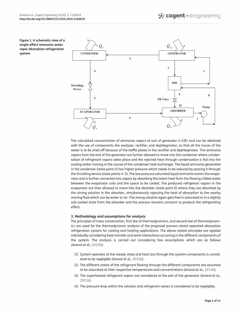
2. System description and working principleThe analyzed system is a process steam-powered single-stage ammonia–water vapor absorption refrigeration system and the line diagram of the system is presented in Figure 1. The system uses ammonia–water as refrigerant–absorbent pair. The main components of the system are similar to those mentioned in the work done by authors (Gupta, Anand, Anand, & Tyagi, 2015) and are a gen-erator, a condenser, an absorber, an evaporator, a SHE, a throttling device, a pressure reducing valve, and a pump.
The working is similar to that explained in the work done by authors (Anand, Gupta, & Tyagi, 2013b) and involves the mechanism that solution having higher concentration of refrigerant leaves the ab-sorber (state point 7) and with the help of a solution pump (state point 8) this refrigerant-rich solution is pumped into the SHE and again gets heated by a solution containing lower concentration of refrig-erant (weak solution) that comes out of the generator. The energized refrigerant-rich solution enters into the generator (state point 1) where the energized liquid ammonia converts in to vapor phase with an external heat from the process steam and separates from the solution. The refrigerant va-pors (ammonia vapors) come out of the generator (state point 2) and the remaining solution called as weak solution moves back to the absorber to increase the concentration of refrigerant via SHE (state points 3–9) by reducing its pressure through pressure-reducing valve (state points 9–10).
Page 4 of 14
Anand et al., Cogent Engineering (2016), 3: 1160639http://dx.doi.org/10.1080/23311916.2016.1160639
The calculated concentration of ammonia vapors at exit of generator is 0.81 and can be obtained with the use of components like analyzer, rectifier, and dephlegmator, so that all the traces of the water is to be shed off because of the baffle plates in the rectifier and dephlegmator. The ammonia vapors from the exit of the generator are further allowed to move into the condenser where conden-sation of refrigerant vapors takes place and the rejected heat through condensation is fed into the cooling water moving in the course of the condenser heat exchanger. The liquid ammonia generated in the condenser (state point 4) has higher pressure which needs to be reduced by passing it through the throttling device (state points 4–5). The low pressure saturated liquid ammonia enters the evapo-rator and is further converted into vapors by absorbing the latent heat from the flowing chilled water between the evaporator coils and the space to be cooled. The produced refrigerant vapors in the evaporator are then allowed to move into the absorber (state point 6) where they are absorbed by the strong solution in the absorber, simultaneously rejecting the heat of absorption to the nearby moving fluid which can be water or air. The strong solution again gets free in saturated or in a slightly sub-cooled state from the absorber and the process remains constant to produce the refrigerating effect.
3. Methodology and assumptions for analysisThe principles of mass conservation, first law of thermodynamics, and second law of thermodynam-ics are used for the thermodynamic analysis of the proposed process steam-operated absorption refrigeration system for cooling and heating applications. The above-stated principles are applied individually considering heat transfer and work interactions occurring in the different components of the system. The analysis is carried out considering few assumptions which are as follows (Anand et al., 2013b):
(1) System operates at the steady state and heat loss through the system components is consid-ered to be negligible (Anand et al., 2013b).
(2) The different states of the refrigerant flowing through the different components are assumed to be saturated at their respective temperatures and concentrations (Anand et al., 2013b).
(3) The superheated refrigerant vapors are considered at the exit of the generator (Anand et al., 2013b).
(4) The pressure drop within the solution and refrigerant valves is considered to be negligible.
Figure 1. A schematic view of a single-effect ammonia–water vapor absorption refrigeration system. GENERATOR
SHE
1
2
34
5
6 7
89
Throttling Device
PR Valve
Pump
EVAPORATOR
CONDENSER
ABSORBER
10
cQ
eQ aQ
gQ
Page 5 of 14
Anand et al., Cogent Engineering (2016), 3: 1160639http://dx.doi.org/10.1080/23311916.2016.1160639
(5) The pump work is neglected considering being operational at isenthalpic conditions.
(6) The dead state enthalpy (h0) and the entropy (s0) for calculating the exergy of the working fluid is considered at an environmental temperature and pressure of 25°C and 1 bar, respectively (Anand et al., 2013b). The reference values of the entropy and enthalpy for the ammonia have been taken from the from external library file of the EES.
The governing generalized equations of mass and material balance for the operation of the sys-tem at steady state are given below (Anand et al., 2013b):
The energy balance of the different components of the absorption refrigeration system is based on the first law of thermodynamics and is given below as (Anand et al., 2013b):
where ‘m’ is the mass flow rate (kg/s), ‘x’ is the concentration of ammonia in the solution, ‘h’ is the enthalpy of the working fluid (kJ/kg). The ‘i’ and ‘o’ are the inlet and outlet states of different compo-nents of the absorption system.
3.1. Energy analysisThe heat load balance equations of different components of a process steam-based vapor absorp-tion refrigeration system are tabulated in Table 1. The different input parameters considered for analysis include generator temperature (Tg) = 100°C, absorber and condenser temperature (Tc = Ta) = 30°C, evaporator temperature (Te) = 5°C, effectiveness of SHE (ϵ) = 0.7. The heat transfer rates of different components along with the COPs are mentioned in the Table 2. The theoretical performance of the system is measured in terms of COP and mathematically it is presented as:
where ‘Qe’ is the cooling effect (kW) and ‘Qg’ is the energy supplied to the generator (kW). However, in case of absorption refrigeration system, the total energy supplied to the system is the sum of the heat supplied to the generator and work consumed by the pump.
Pump work WP is calculated to be very small and therefore is not considered in calculating the actual COP of the system (Gupta et al., 2015). The COP of the vapor absorption system in the present analysis is calculated from the equation given below:
(1)∑
mi −∑
mo = 0
(2)∑
(mx)i −∑
(mx)o = 0
(3)∑
(
mh)
i−∑
(
mh)
o+
[
∑
Qi −∑
Qo
]
± W = 0
(4)COP =Qe
(
Qg + WP
)
Table 1. Energy balance equations of the different components in an absorption refrigeration systemS. No Components Energy balance equation1 Generator Qg = m2 h2 + m3 h3 − m1 h1
2 Condenser Qc = m2
(
h2 − h4
)
3 Evaporator Qe = m2
(
h6 − h5
)
4 Absorber Qa = m2 h6 + m3 h10 − m1 h7
5 Solution heat exchanger Qshe = m3
(
h3 − h9
)
= m1
(
h1 − h8
)

Page 6 of 14
Anand et al., Cogent Engineering (2016), 3: 1160639http://dx.doi.org/10.1080/23311916.2016.1160639
The heat of condensation and heat of absorption rejected to the flowing water or air from the con-denser and absorber respectively can also be utilized for heating purposes and the heating COP of the system is given below as:
where ‘QC’ and Qa are the rejected heat flow (kW) from the condenser and absorber respectively to water or air.
The circulation ratio of the system can be defined as given below in Equation (7):
3.2. Second law analysis (exergy analysis)The second law analysis is based on the concept of exergy which measures the maximum theoreti-cal work that can be obtained by the interaction of an energy resource with reference state i.e. envi-ronmental conditions. The different losses in the individual components as well as in the whole system can be evaluated with the help of exergy analysis. The main reasons behind the losses in the system includes friction, heat transfer under temperature difference, enriching process occurring in the rectifier and dephlegmator, and unrestricted expansion (American Society of Heating, Refrigeration and Air-conditioning Engineers, 1997).
The exergy analysis predicts the magnitude of the losses which helps to understand the compo-nents requiring more attention for modification in order to improve the performance of the system. The exergy analysis also helps to determine the optimum operating conditions of the system. The physical exergy is the maximum useful work that can be obtained when unit of mass of a substance at required pressure and temperature conditions is allowed to pass under ambient pressure and temperature conditions (Gupta et al., 2015). Physical exergy can also be defined as the amount of work required to bring matter from generic state to a state which is in thermal and mechanical equi-librium with the ambient (environmental) conditions and is represented as (Bejan, Tsatsaronis, & Moran, 1995):
(5)COPCooling =Qe
Qg=
m2
(
h6 − h4)
m2 h2 + m3 h3 − m1 h1
(6)COPHeating =QC + Qa
Qg=m2
(
h2 − h4)
+ m2 h6 + m3 h10 − m1 h7
m2 h2 + m3 h3 − m1 h1
(7)f =m1
m2
(8)𝛹 = m[(
h − ho)
− To(
s − so)]
Table 2. Heat transfer at various components and performance parameters of the systemS. No Components Heat transfer (kW)1 Generator (‘Qg’) 482.2
2 Condenser (‘Qc’) 470.7
3 Evaporator (‘Qe’) 183.8
4 Absorber (‘Qa’) 195.3
5 Solution heat exchanger (‘Qshe’) 357.6
Coefficient of performance for cooling (COPCooling) 0.381
Coefficient of performance for heating (COPHeating) 1.381
Circulation ratio (f) 3.726

Page 7 of 14
Anand et al., Cogent Engineering (2016), 3: 1160639http://dx.doi.org/10.1080/23311916.2016.1160639
where ‘Ψ’ is the exergy (kW) of the fluid at temperature ‘T’ (K). The terms ‘h’ and ‘s’ are the en-thalpy and entropy (kJ/kg-K) of the fluid, whereas, ‘ho’ and ‘so’ are the enthalpy and entropy of the working fluid at ambient temperature ‘To’. In this study ‘To’ is taken as 298 K and ambient pressure is taken as 1 bar .The equations to calculate the exergy balance of different components of the absorp-tion refrigeration system are listed in Table 3 and the results so obtained from the analysis are listed in the Table 4. The second law performance of the system can be measured in terms of exergetic efficiency which is defined as the ratio of the useful exergy gained from a system to that supplied to the system. Hence, the exergetic efficiency of the absorption system for cooling and heating applica-tion is given as:
where
(9)𝜂𝛹Cooling =
m2 𝛹6 − m2 𝛹5
m2 𝛹2 + m3 𝛹3 − m1 𝛹1
(10)𝜂𝛹Heating =
(
m2 𝛹2 − m2 𝛹4
)
+(
m2 𝛹6 + m3 𝛹10 − m1 𝛹7
)
m2 𝛹2 + m3 𝛹3 − m1 𝛹1
�1 =[(
h1 − ho)
− To(
s1 − so)]
�2 =[(
h2 − ho)
− To(
s2 − so)]
�3 =[(
h3 − ho)
− To(
s3 − so)]
�4 =[(
h4 − ho)
− To(
s4 − so)]
�5 =[(
h5 − ho)
− To(
s5 − so)]
Table 3. Exergy balance equations of the various components in an absorption refrigeration systemS. No Component Exergy balance equation1 Generator m2
[(
h2 − ho
)
− To
(
s2 − so
)]
+ m3
[(
h3 − ho
)
− To
(
s3 − so
)]
− m1
[(
h1 − ho
)
− To
(
s1 − so
)]
2 Evaporator m2
[(
h6 − ho
)
− To
(
s6 − so
)]
− m2
[(
h5 − ho
)
− To
(
s5 − so
)]
3 Condenser m2
[(
h2 − ho
)
− To
(
s2 − so
)]
− m2
[(
h4 − ho
)
− To
(
s4 − so
)]
4 Absorber m2
[(
h6 − ho
)
− To
(
s6 − so
)]
+ m3
[(
h9 − ho
)
− To
(
s9 − so
)]
− m3
[(
h1 − ho
)
− To
(
s1 − so
)]
Table 4. General results obtained from the thermodynamic simulationState point
Temperature (K)
X (%NH3) Pressure P (bar)
Enthalpy (kJ /kg)
Exergy (kW)
Entropy (kJ/kg-K)
1 373.1 0.38 12 293.9 −324.4 1.44
2 423.1 0.8106 12 1,761 −15.55 5.467
3 423.1 0.222 12 415 −195 1.652
4 303.1 0.8106 12 6.926 −81.57 0.4081
5 256.8 0.8106 1.7 6.926 −87.35 0.4803
6 278.1 0.8106 1.7 691.6 −110.3 3.064
7 303.1 0.38 1.7 −63.65 −274.8 0.4118
8 303.1 0.38 1.7 −63.65 −274.8 0.4118
9 290.3 0.222 12 −73.76 −243.1 0.2325
10 290.3 0.222 12 −73.76 −243.1 0.2325

Page 8 of 14
Anand et al., Cogent Engineering (2016), 3: 1160639http://dx.doi.org/10.1080/23311916.2016.1160639
The term Ψ & ηΨ represents the specific exergy (kJ/kg) and exergy efficiency, respectively. The nu-meric subscripts represent the different state points of the system as given in Figure 1. The sub-scripts like a, c, g, e, p, Ψ, cooling and heating represent absorber, condenser, generator, evaporator, pump, exergy, cooling and heating efficiencies, respectively. Based on the equations for heat and mass balances, the heat transfer equations at different state points, a simulation program has been developed to calculate the exergy as well as energy of the absorption refrigeration system. The vari-ous input parameters are considered in the analysis as described earlier. The analysis depends on the various assumptions which are also considered as mentioned below in the next section.
4. Results and discussionEngineering Equation Solver (EES) (Klein & Alvarado, 2012) software has been used to develop a computer program for carrying out energy and exergy analysis of process steam-based ammonia–water vapor absorption refrigeration system for cooling and heating applications (Anand et al., 2013b). The simulation of the system is carried out for the generator temperature = 100°C, con-denser and absorber temperature = 30°C, evaporator temperature = 5°C, effectiveness of SHE = 0.6, high pressure = 12 bar, and low pressure = 1.7 bar. Add-in function of external library file of the EES was used to calculate thermodynamic properties of refrigerant at different state points in the system to be analyzed (Anand et al., 2013b). The results obtained from simulation are given in the Tables 2 and 4 and are graphically presented in the Figures 2–9. The variation in the heat source temperature, evaporator temperature, condenser and absorber temperatures are used to study the effect on the COP, exergy loss in the different components of an absorption system and exergy efficiency of the system.
The varying behavior of COP and exergy efficiency of the absorption system for cooling and heat-ing applications with generator temperatures is shown in Figure 2 and it becomes evident that with the rise in generator temperature, the COP for cooling and heating applications as well as exergetic efficiency shows a rising trend. The behavior of the COP for cooling applications shows the trend because with rising generator temperature the temperature of the refrigerant also increases and
�6 =[(
h6 − ho)
− To(
s6 − so)]
�7 =[(
h7 − ho)
− To(
s7 − so)]
�10 =[(
h10 − ho)
− To(
s10 − so)]
Figure 2. Variation of COP and exergy efficiency of the system with generator temperature for cooling and heating applications (Te = 5°C, Tc = Ta = 30°C).
0.1
0.15
0.2
0.25
0.3
0.35
0.4
0
0.3
0.6
0.9
1.2
1.5
1.8
60 66 72 78 84 90 96 102 108 115
Generator Temperature (oC)
Exe
rgy
Eff
icie
ncy
CO
P
COPCooling COPHeating ηψ
Page 9 of 14
Anand et al., Cogent Engineering (2016), 3: 1160639http://dx.doi.org/10.1080/23311916.2016.1160639
more refrigerant vapors are generated, subsequently leading to the higher rate of heat transfer in the generator which is a heat exchanger provided with baffles in it to remove water from the refrig-erant and is further allowed to pass into the condenser. Although, the rising generator temperature raises more refrigerant vapors, it also introduces more irreversibility because of the supply of the more input exergy which subsequently increases the exergy efficiency of the system. The heating COP shows an increasing trend as shown in Figure 2 because of the fact that with an increasing generator temperature, more refrigerant vapors are produced and the same can be transferred to the condenser where heat rejected during condensation process can be utilized for heating purpos-es. Besides, the heat rejection from the absorber due to the intermixing of two different streams of
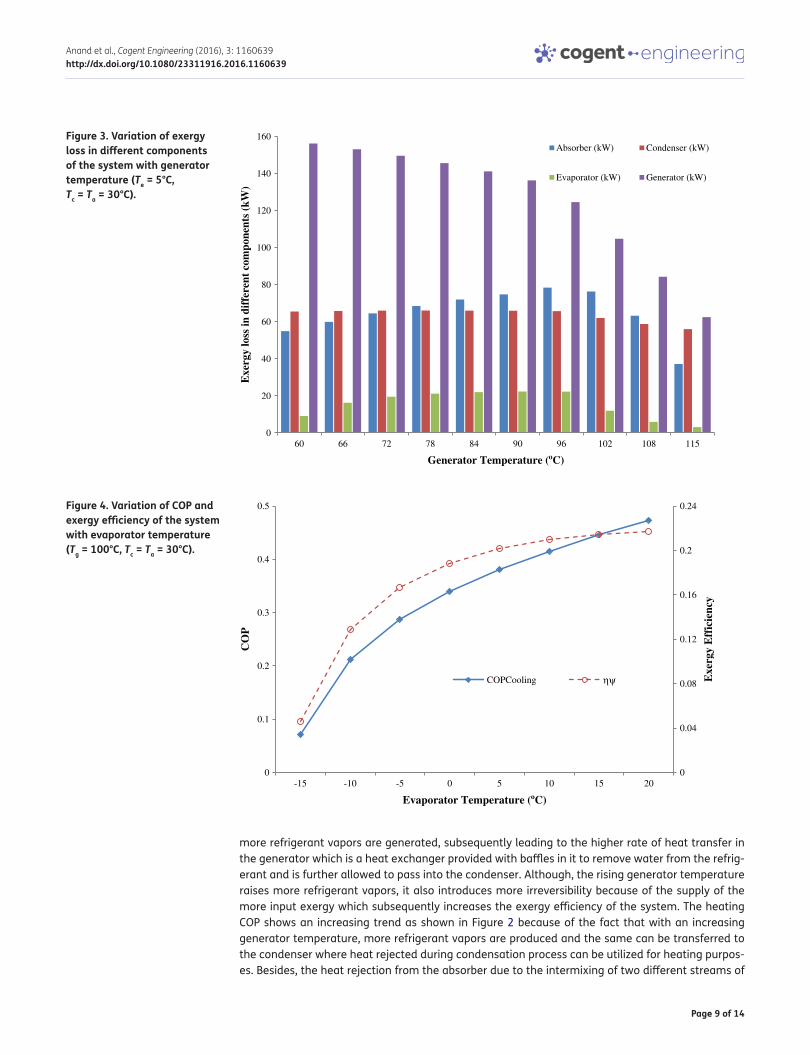
Figure 3. Variation of exergy loss in different components of the system with generator temperature (Te = 5°C, Tc = Ta = 30°C).
0
20
40
60
80
100
120
140
160
60 66 72 78 84 90 96 102 108 115
Exe
rgy
loss
in d
iffe
rent
com
pone
nts
(kW
)
Generator Temperature (oC)
Absorber (kW) Condenser (kW)
Evaporator (kW) Generator (kW)
Figure 4. Variation of COP and exergy efficiency of the system with evaporator temperature (Tg = 100°C, Tc = Ta = 30°C).
0
0.04
0.08
0.12
0.16
0.2
0.24
0
0.1
0.2
0.3
0.4
0.5
-15 -10 -5 0 5 10 15 20
Exe
rgy
Eff
icie
ncy
CO
P
Evaporator Temperature (oC)
COPCooling ηψ

Page 10 of 14
Anand et al., Cogent Engineering (2016), 3: 1160639http://dx.doi.org/10.1080/23311916.2016.1160639
solution having different temperature can also be utilized for heating applications. Both the pro-cesses discussed above contribute to increase the COP of the system.
The effect of the generator temperature on the exergy loss in different components of the system can be seen in Figure 3 which clearly predicts that with an increase in the generator temperature, the exergy loss in the absorber increases up to a temperature of 96°C and shows a decreasing trend with further increase in the generator temperature. However, for evaporator, the exergy loss in-creases up to 90°C and thereafter shows a decreasing trend with further increase in the generator temperature. The exergy loss in generator decreases continuously with an increase in the generator
Figure 5. Variation of COP and exergy efficiency of the system with absorber and condenser temperature (Tg = 100°C, Te = 5°C).
0
0.05
0.1
0.15
0.2
0.25
0
0.09
0.18
0.27
0.36
0.45
10 14 18 23 27 32 36 41 45 50
Exe
rgy
Eff
icie
ncy
CO
P
Absorber and Condenser Temperature (oC)
COP ηEx
Figure 6. Variation of COP and exergy efficiency of the system with generator temperature at different evaporator temperatures (Tc = Ta = 30°C).
0
0.08
0.16
0.24
0.32
0.4
0
0.15
0.3
0.45
0.6
0.75
0.9
60 66 72 78 84 90 96 102 108 115
Exe
rgy
Eff
icie
ncy
CO
P
Generator Temperature (oC)
COP (Te= -15°C) COP (Te= -5°C ) COP (Te= 0°C) COP (Te= 5°C)
COP (Te= 15°C) ηψ (Te= -15°C) ηψ (Te= -5°C) ηψ (Te=0°C)
ηψ (Te= 5°C) ηψ (Te= 15°C)

Page 11 of 14
Anand et al., Cogent Engineering (2016), 3: 1160639http://dx.doi.org/10.1080/23311916.2016.1160639
temperature. The exergy loss in condenser increases up to a temperature of 84°C and then shows a descending trend with further rise in the generator temperature.
The effect on COP and exergy efficiency with variation in evaporator temperature can be seen in Figure 4 and it becomes evident that with increasing evaporator temperature the COP shows a rising trend because of the fact that at higher evaporator temperature, the corresponding pressure in-creases which increases the absorption efficiency of the strong solution in the absorber as it is work-ing under the same pressure conditions of the evaporator which subsequently improves the COP of the system. The trend of the exergy efficiency can also be seen increasing with rising evaporator temperature and can be explained through the second law of thermodynamics that lower evapora-tor temperatures produce more efficient cooling effect. The exergy efficiency in this case is also
Figure 7. Variation of COP and exergy efficiency of the system with evaporator temperature at different generator temperatures (Tc = Ta = 30°C).
0
0.08
0.16
0.24
0.32
0
0.12
0.24
0.36
0.48
0.6
0.72
-15 -10 -5 0 5 10 15 20
Exe
rgy
Eff
icie
ncy
CO
P
Evaporator Temperature (oC)
COP (Tg=60°C ) COP (Tg=80°C) COP (Tg=100°C) COP (Tg=110°C)
ηψ (Tg=60°C) ηψ (Tg=80°C) ηψ (Tg=100°C) ηψ (Tg=110°C)
Figure 8. Variation of COP and exergy efficiency of the system with generator temperature at different absorber and condenser temperatures (Te = 5°C).
0
0.09
0.18
0.27
0.36
0.45
0
0.17
0.34
0.51
0.68
0.85
60 66 72 78 84 90 96 102 108 115
Exe
rgy
Eff
icie
ncy
CO
P
Generator Temperature (oC)
COP (Tc=Ta=10°C) COP (Tc=Ta=20°C) COP (Tc=Ta=30°C) COP (Tc=Ta=40°C)
COP (Tc=Ta=50°C) ηψ (Tc=Ta=20°C) ηψ (Tc=Ta=10°C) ηψ (Tc=Ta=30°C)
ηψ (Tc=Ta=40°C) ηψ (Tc=Ta=50°C)

Page 12 of 14
Anand et al., Cogent Engineering (2016), 3: 1160639http://dx.doi.org/10.1080/23311916.2016.1160639
influenced by the temperature difference between the environment and the refrigerated space to be cooled (Anand et al., 2013b). The influence of the absorber and condenser temperatures on the COP and exergy efficiency is shown in Figure 5 and becomes evident from the figure that both COP as well as exergetic efficiency of the system show a decreasing trend with rising absorber and condenser temperatures and this is happening because with an increase in the condenser temperature, the system pressure in the generator will decrease, which results in release of lesser ammonia vapors leading to lower performance of the system. Hence, this clearly indicates that the choice of suitable absorber and condenser temperatures is a better option to improve the COP of the system.
The effect on COP and exergy efficiency of the system for cooling applications with generator temperature at different evaporator temperatures is shown in Figure 6 which clearly states that with rise in the generator temperature for varying evaporator temperatures, the highest COP and exer-getic efficiency can be obtained at a superior value of evaporator temperature. Again, Figure 7 re-vealed the influence on the COP and exergy efficiency of the absorption system for cooling applications with evaporator temperature at varying generator temperatures and it becomes evi-dent that with rising evaporator temperature for different generator temperatures, the highest COP and exergy efficiency for cooling applications can be obtained at upper values of generator temperatures.
Figure 8 shows influence on the COP and exergy efficiency with generator temperature at varying absorber and condenser temperatures and it becomes apparent that with rise in generator tem-perature for varying absorber and condenser temperatures, the highest COP and exergy efficiency can be obtained at lower absorber as well as condenser temperatures and the same trend can be seen in Figure 9 for heating applications, clearly indicating that lower absorber and condenser tem-peratures provide a higher value of COP.
5. ConclusionsThe generated simulation program using the first and second laws of thermodynamics to predict the performance process steam-based single-effect ammonia–water vapor absorption system revealed that operating parameters affect the performance of the system. The analysis shows that the exergy loss in generator is found to be the highest, while it is found to be the lowest in case of evaporator. The exergy losses in absorber are found to be greater in comparison to condenser which is the actual case and therefore, it is important to improve the design of the generator and absorber for improv-ing the efficiency of the system. The ambient temperature (dead state temperature) also affects the
Figure 9. Variation of COP and exergetic efficiency of the system with generator temperature at different absorber and condenser temperatures for heating applications (Te = 5°C).
1
1.15
1.3
1.45
1.6
1.75
1.9
60 66 72 78 84 90 96 102 108 115
CO
P
Generator Temperature (oC)
COP (Tc=Ta=10°C)
COP (Tc=Ta=20°C)
COP (Tc=Ta=30°C)
COP (Tc=Ta=40°C)
COP (Tc=Ta=50°C)

Page 13 of 14
Anand et al., Cogent Engineering (2016), 3: 1160639http://dx.doi.org/10.1080/23311916.2016.1160639
exergy efficiency of the system and it should be chosen in a way so that the exergetic losses can be minimized for better optimization of the system. An appropriate selection and realization of genera-tor and evaporator temperatures for their respective operation can draw out more efficiency from the system. Also, the results obtained with respect to exergy loss in each component and exergy efficiency are very important for the optimization of the system and will also be useful to improve the performance of the system.
FundingThe authors received no direct funding for this research.
Author detailsS. Anand1
E-mail: [email protected]. Gupta1
E-mail: [email protected]. Anand1
E-mail: [email protected]. Tyagi2
E-mail: [email protected] School of Energy Management, Shri Mata Vaishno Devi
University, Katra 182320, Jammu & Kashmir, India.2 Biomass and Energy Management Division, Sardar Swaran
Singh National Institute of Renewable Energy, Kapurthala 144601, Punjab, India.
Citation informationCite this article as: Use of process steam in vapor absorption refrigeration system for cooling and heating applications: An exergy analysis, S. Anand, A. Gupta, Y. Anand & S.K. Tyagi, Cogent Engineering (2016), 3: 1160639.
ReferencesAbu-Ein, S. Q., Sayel, M. F., Momani, W., & Al-Bousoul, M.
(2009). Performance analysis of solar powered absorption refrigeration system. Heat and Mass Transfer, 46, 137–145. doi:10.1007/s00231-009-0538-1.
Adewusi, S. A., & Zubair, S. M. (2004). Second law based thermodynamic analysis of ammonia-water absorption systems. Energy Conversion and Management, 45, 2355–2369. doi:10.1016/j.enconman.2003.11.020.
Anand, S., Gupta, A., & Tyagi, S. K. (2013a). Simulation studies of refrigeration cycles: A review. Renewable and Sustainable Energy Reviews, 17, 260–277. doi:10.1016/j.rser.2012.09.021.
Anand, S., Gupta, A., & Tyagi, S. K. (2013b). Thermodynamic analysis of 1TR biogas based NH3-H2O vapor absorption system. In Recent Advances in Bioenergy Research (Vol. II, Chap. 8, pp. 79–98). Kapurthala: SSS-NIRE. ISBN: 978-81-927097-1-0.
Anand, S., Gupta, A., & Tyagi, S. K. (2014a). Renewable energy powered evacuated tube collector refrigerator system. Mitigation and Adaptation Strategies for Global Change, 19, 1077–1089. doi:10.1007/s11027-013-9461-3.
Anand, S., Gupta, A., & Tyagi, S. K. (2014b). Critical analysis of a biogas powered absorption system for climate change
mitigation. Clean Technologies and Environmental Policies, 16, 569–578. doi:10.1007/s10098-013-0662-y.
ASHRAE. (1997). Inclusive fundamentals handbook (SI edition). Author.
Bejan, A., Tsatsaronis, G., & Moran, M. (1995). Thermal design and optimization. Ney York, NY: Wiley.
Gupta, A., Anand, Y., Anand, S., & Tyagi, S. K. (2015). Thermodynamic optimization and chemical exergyquantification for absorption-based refrigeration. Journal of Thermal Analysis and Calorimetry, 122, 893–905. doi:10.1007/s10973-015-4795-6.
Gordon, J. M., & Ng, K. C. (2000). Cool thermodynamics: Engineering and physics of predictive, diagnostic and optimization methods for cooling systems. Cambridge: International Science Publishing.
Kaynakli, O., & Kilic, M. (2007). Theoretical study on the effect of the operating parameters on the performance of absorption refrigeration system. Energy Conversion and Management, 48, 599–607. doi:10.1016/j.enconman.2006.06.005.
Kim, B., & Park, J. (2007). Dynamic simulation of a single-effect ammonia water absorption chiller. International Journal of Refrigeration, 30, 535–545. doi:10.1016/j.ijrefrig.2006.07.004.
Klein, S.A., & Alvarado, F. (2012). Engineering equation solver version 9.083. Middleton, WI: F-Chart Software.
Kotas, T. J. (1985). The exergy method of thermal plant analysis. London: Butterworth.
Lee, S. F., & Sherif, S. A. (2001). Second law analysis of various double-effect lithium bromide/water absorption chillers. ASHRAE Transactions, 1, 664–673.
Muthu, V., Saravana, R., & Renganarayanan, S. (2008). Experimental studies of 134a–DMAC hot water based vapor absorption refrigeration system. International Journal of Thermal Sciences, 47, 175–181. doi:10.1016/j.ijthermalsci.2007.02.004.
Romero, R. J., Guillen, L., & Pilatowsky, I. (2005). Mono-methylamine-water vapor absorption refrigeration system. Applied Thermal Engineering, 25, 867–876. doi:10.1016/j.applthermaleng.2004.08.007.
Roy, S., & Maiya, M. P. (2012). Investigations on 134a–DMAC based vapor absorption refrigeration system with add on components. International Journal of Thermal Sciences, 59, 224–233. doi:10.1016/j.ijthermalsci.2012.03.011.
Talbi, M. M., & Agnew, B. (2000). Exergy analysis: An absorption refrigerator using lithium bromide and water as the working fluids. Applied Thermal Engineering, 20, 619–630. doi:10.1016/S1359-4311(99)00052-6.

Page 14 of 14
Anand et al., Cogent Engineering (2016), 3: 1160639http://dx.doi.org/10.1080/23311916.2016.1160639
© 2016 The Author(s). This open access article is distributed under a Creative Commons Attribution (CC-BY) 4.0 license.You are free to: Share — copy and redistribute the material in any medium or format Adapt — remix, transform, and build upon the material for any purpose, even commercially.The licensor cannot revoke these freedoms as long as you follow the license terms.
Under the following terms:Attribution — You must give appropriate credit, provide a link to the license, and indicate if changes were made. You may do so in any reasonable manner, but not in any way that suggests the licensor endorses you or your use. No additional restrictions You may not apply legal terms or technological measures that legally restrict others from doing anything the license permits.
Cogent Engineering (ISSN: 2331-1916) is published by Cogent OA, part of Taylor & Francis Group. Publishing with Cogent OA ensures:• Immediate, universal access to your article on publication• High visibility and discoverability via the Cogent OA website as well as Taylor & Francis Online• Download and citation statistics for your article• Rapid online publication• Input from, and dialog with, expert editors and editorial boards• Retention of full copyright of your article• Guaranteed legacy preservation of your article• Discounts and waivers for authors in developing regionsSubmit your manuscript to a Cogent OA journal at www.CogentOA.com