US-ILC Waveguide Industrialization Study Marc Ross, Chris Nantista and Chris Adolphsen.
25
US-ILC Waveguide Industrialization Study Marc Ross, Chris Nantista and Chris Adolphsen
-
Upload
jemimah-roberts -
Category
Documents
-
view
213 -
download
0
Transcript of US-ILC Waveguide Industrialization Study Marc Ross, Chris Nantista and Chris Adolphsen.

US-ILC Waveguide Industrialization Study
Marc Ross, Chris Nantista and Chris Adolphsen

For low power RDR-like option, one klystron powers 1 ½ “rf units” or 4 ½ cryomodules.
RF UNIT: 3 cryomodules (26 cavities)6 windows(assuming ~2 MW capability)
from 10 MW klystron
variable power divider, pressurizable, 0-100%, phase stablepressure windowvariable H-hybrid, non-press., limited range5 MW load
ILC Local Power Distribution System (LPDS)
9 cavities 9 cavities 4 cavities quad 4 cavities
WR770 run
Original layout
New layoutBeam current lowered, 1/3 of klystrons eliminated

isolator w/ pickups
bellows
phase shifter
cavity coupler
variable power divider
variable H-hybrids
WR650 waveguideload
loads
pressure window
POWER FLOW
Detailed View of 13-Cavity LPDS UnitPower to each ½ cryomodule is fully adjustable via VPD’s without affecting phases.
Unused power can be dumped to the end load.
Each cavity feed line has a phase shifter, isolator w/ bi-directional coupler, and flex guide

Tunnel End View

Feeding 3 Stations with 2 Klystrons
WR770 used for long runs.
Extra 23 port network needed at klystron.

Standard Waveguide and Waveguide Components
Straight sections E-plane and H-plane bends
T-splitters and magic T's
folded magic T
Need pressurizable and non-pressurizable versions,for stress relief in upper waveguide runs and at cavities.
Semi-flex waveguides

Isolator and Loads
Newer model includes forward and reflected pick-ups, eliminating the need for a separate bi-directional coupler (reflectometer)*.
S.P.A. Ferrite, Ltd. (Russia)
Water cooled (2 types)Ppk Pav
2 MW 10 kW5 MW 100 kW* But costed as separate components
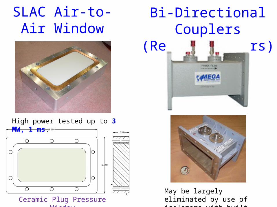
SLAC Air-to-Air Window
High power tested up to 3 MW, 1 ms.
Ceramic Plug Pressure Window
Bi-Directional Couplers(Reflectometers)
May be largely eliminated by use of isolators with built-in pick-ups.

Phase ShiftersDESY/SPA Ferrite KEK/Toshiba

KEK Variable H-Hybrid (Power Divider)
Variable H-hybrid geometry, sample field pattern and in-line port design modification. Moving the two suspended conductors in and out perturbs the relative phase between the two modes supported in the interior section while retaining match, resulting in a varying power split at the output ports.
Sergey Kazakov

U-Bend Phase Shifter
C. Nantista
= 2 U-bend phase shifters + 2 folded magic-T's
SLAC Variable Power Divider
(VPD)
simulation field plot

12
XFEL PDS:
XFEL – Mega: ~ 7K$ / cavity

• Three kinds of parts:1. Catalog items (cost basis from Mega/Furukawa;
LC=0.95) (modification may be required for pressurization)
2. Loads / Circulators (cost basis SPA Ferrite – St. Petersburg; same LC)
3. SLAC / KEK in-house designs with integrated electro-mechanical actuator; based on WR650 hardware (cost basis from first article; same LC)
TDR cost distribution for the above three kinds: 27% 29% 44% (including K-PDS) 13
ILC PDS:
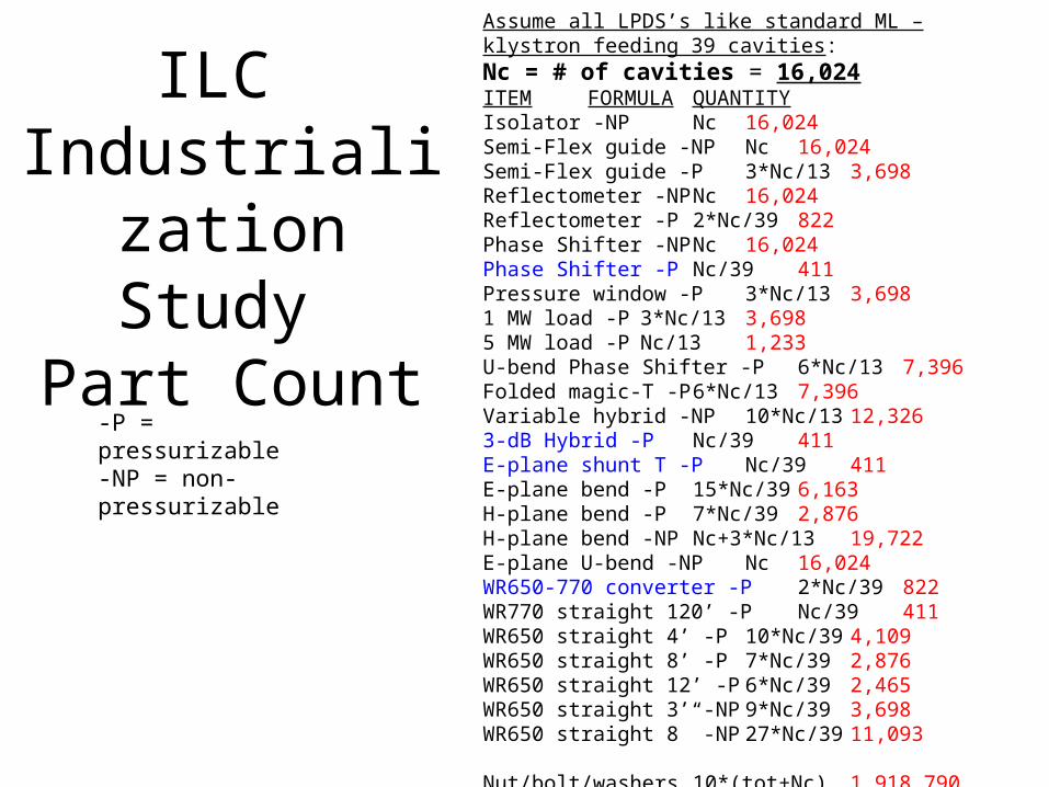
Assume all LPDS’s like standard ML – klystron feeding 39 cavities:Nc = # of cavities = 16,024ITEM FORMULA QUANTITYIsolator -NP Nc 16,024Semi-Flex guide -NP Nc 16,024Semi-Flex guide -P 3*Nc/13 3,698 Reflectometer -NP Nc 16,024Reflectometer -P 2*Nc/39 822Phase Shifter -NP Nc 16,024Phase Shifter -P Nc/39 411Pressure window -P 3*Nc/13 3,698 1 MW load -P 3*Nc/13 3,6985 MW load -P Nc/13 1,233U-bend Phase Shifter -P 6*Nc/13 7,396Folded magic-T -P 6*Nc/13 7,396Variable hybrid -NP 10*Nc/13 12,3263-dB Hybrid -P Nc/39 411E-plane shunt T -P Nc/39 411E-plane bend -P 15*Nc/39 6,163H-plane bend -P 7*Nc/39 2,876H-plane bend -NP Nc+3*Nc/1319,722E-plane U-bend -NP Nc 16,024 WR650-770 converter -P 2*Nc/39 822WR770 straight 120’ -P Nc/39 411WR650 straight 4’ -P 10*Nc/39 4,109WR650 straight 8’ -P 7*Nc/39 2,876WR650 straight 12’ -P 6*Nc/39 2,465WR650 straight 3’ -NP 9*Nc/39 3,698WR650 straight 8” -NP 27*Nc/39 11,093
Nut/bolt/washers 10*(tot+Nc) 1,918,790
ILC Industrialization
Study Part Count
-P = pressurizable-NP = non-pressurizable

• Twelve production schemes considered:– deliver full, only standard waveguide, only circulators and loads,
and only electromechanical devices – at 3 varied production levels (25%, 50% and 100%) – over a period of 6 years with up to 2 additional years for the
following to be completed:
a. Casting and extrusion tooling and process development / qualification
b. Facility build-out
c. Equipment and workstation installation and pre-production verification /
release
d. Production tooling and process development and qualification
• The results of this study include plant layouts, time planning for equipment and labor, work flow diagrams, and costs for the industrial components of plan estimated at 2013 prices and rates
15
Post-TDR MEGA Cost Study Scope

– Plant equipment requirements, including building, technical
equipment, and layout of equipment in building. Costs, in 2013
dollars, to create such a facility, and time required to build,
prepare, and prove the plant is ready for production.
– A production plan, including labor and machine hours required.
– Identification of the top 3 throughput bottlenecks in the plant, and
the remedy for each.
– Analysis of alternatives for each production step, and
identification of the top 3 alternatives which should be pursued
with R&D to have the greatest economic effect on the
production.
Specific Report Items (1):

– Identification of components or subcomponents that are prime
candidates for subcontracting, including description of existing
companies that could fulfill such roles or a description of an
industry where such subcontracting should be pursued.
– Identification of particularly economically burdensome
production process requirements or component tolerances
which are, and possible remedies for such.
– Identification of the hub Laboratory contributions, the reasoning
for the choice, and a description of the technical criteria that
would define such a handoff.
Specific Report items (2)

Fabrication TasksAssemblyBlendingBrazing
Manual MillsClean / MaskCompressionConvoluter
Copper PlateElectrical Test
EMMEGIFinal InspectionForming / Weld
Heat TreatIn-Process Insp
630 mm HMC630 mm VMC
1,000 mm HMCPack / Ship
PaintPressure Test
RinseRouterSaws
Silver PlateSolder
300 mm LatheAutowelderTIG Welder

Example: TIG Welding

The Project Timeline captures the major milestones of the facility build out and ramp up to meet the production demand timeline.

Learning Curves
• “The purely mechanical straights and sweeps will quickly hit a production plateau gaining potentially a 10% improvement over time as the workers become more comfortable with the serial production operations and techniques during the first year of production.
• The more complex components will take significantly more time to attain optimized throughput levels, but we believe a 20% or more improvement may be possible.”

Top 3 Processes• Machining (assumes 85% machinery utilization over
two 8 hour shifts per day, five days per week)• Welding• Testing (to be shared with hub – lab)
• These are also the three potential bottlenecks they identified – in particular, in regard to– Equipment up time (5% downtime in PY1 and 3% in years
PY2 – PY6)– Employee availability– Raw material supply

Hub Lab Tasks
• High power rf testing• Electro-mechanical integration (final assembly of
subassemblies with motorized drives)• Final PDS integration and tuning

Possible Improvements
• Integration of special components– Electromechanical devices, typ. SLAC / KEK designs
• Extrusion• Casting• Testing automation
May provide 20 to 30% cost reduction

Summary• Industrialization study of ‘non-high-tech’
components (PDS) completed March 2014– US PDS industry is small-business based– Substantial cost-reduction (~1% of ILC total)
possible with nominal R&D investment