International Linear Collider (ILC) Linac Basics Part I: General Design Constraints Part II: ILC...
74
International Linear Collider (ILC) Linac Basics Part I: General Design Constraints Part II: ILC Design Choices Chris Adolphsen SLAC
-
Upload
ross-mclaughlin -
Category
Documents
-
view
229 -
download
0
Transcript of International Linear Collider (ILC) Linac Basics Part I: General Design Constraints Part II: ILC...

International Linear Collider (ILC) Linac Basics
Part I: General Design Constraints
Part II: ILC Design Choices
Chris AdolphsenSLAC

• Linear collider design is complex due to the interrelationships among the various parameters and the soft constraints on their values.
• I will give one or many possible descriptions of the rationale behind the ILC linac design.
Bob Palmer1990
Part I: General Design Constraints

‣ Made with solid, pure niobium – it has the highest Critical
Temperature (Tc = 9.2 K) and Thermodynamic Critical Field
(Bc ~ 1800 Gauss) of all metals.
‣ Nb sheets are deep-drawn to make cups, which are e-beam
welded to form cavities.
‣ Cavity limited to ~ 9 cells (~ 1 m Long) to reduce trapped
modes, input coupler power and sensitivity to frequency
errors.
‣ Iris radius (a) of 35 mm chosen in tradeoff for low surface
fields, low rf losses (~ a), large mode spacing (~ a3 ), small
wakes (~ a-3.5 ).
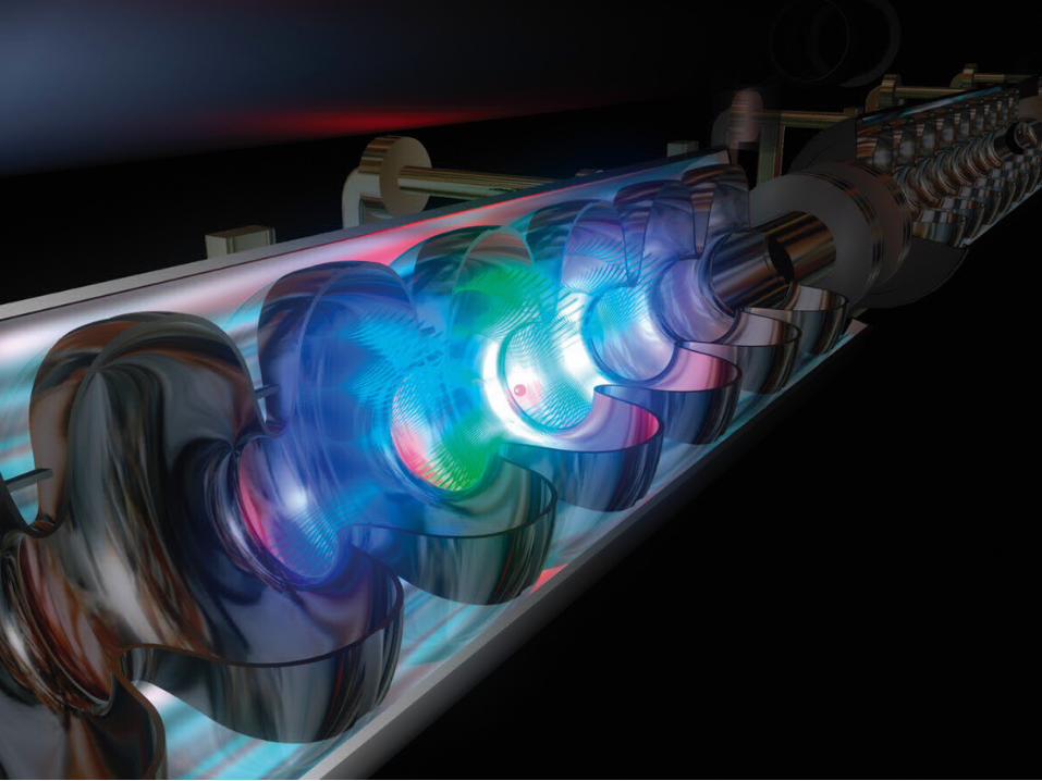
1.3 GHz TESLA
Cavities

The Basics• The low rf surface losses in superconducting
cavities allow essentially 100% RF-to-beam transfer efficiency in steady state:
RF Input Power = Cavity Voltage * Beam Current
• First look at what limits cavity voltage (gradient * cavity length)
– Note: highest gradient not always cost optimal !

Cavity Operating Parameters• Operate at 2K (in super-fluid He)
to reduce resistivity:
• 1.3 GHz frequency (f) chosen to reduce power loss, sensitivity to thermal instabilities, wakes, and cavity size and to match available sources.
• At Qo = 1e10, cavity time constant (Qo/) ~ 1 sec, and at 35 MV/m and 0.1% duty factor, average power loss ~ 1 W/m (but it takes ~ 1 kW/m of AC power to remove heat).
1.31.82.3 1.53.14.6
Qo ~ 2e10at T = 2K
Temperature (K)
Niobium Surface Resistance
Qo
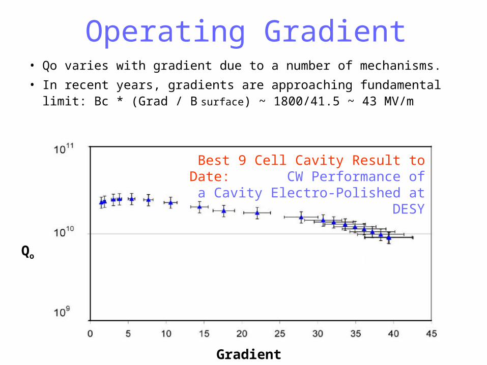
Gradient (MV/m)
Best 9 Cell Cavity Result to Date: CW Performance of a Cavity
Electro-Polished at DESY
Operating Gradient• Qo varies with gradient due to a number of mechanisms.
• In recent years, gradients are approaching fundamental limit: Bc * (Grad / B surface) ~ 1800/41.5 ~ 43 MV/m
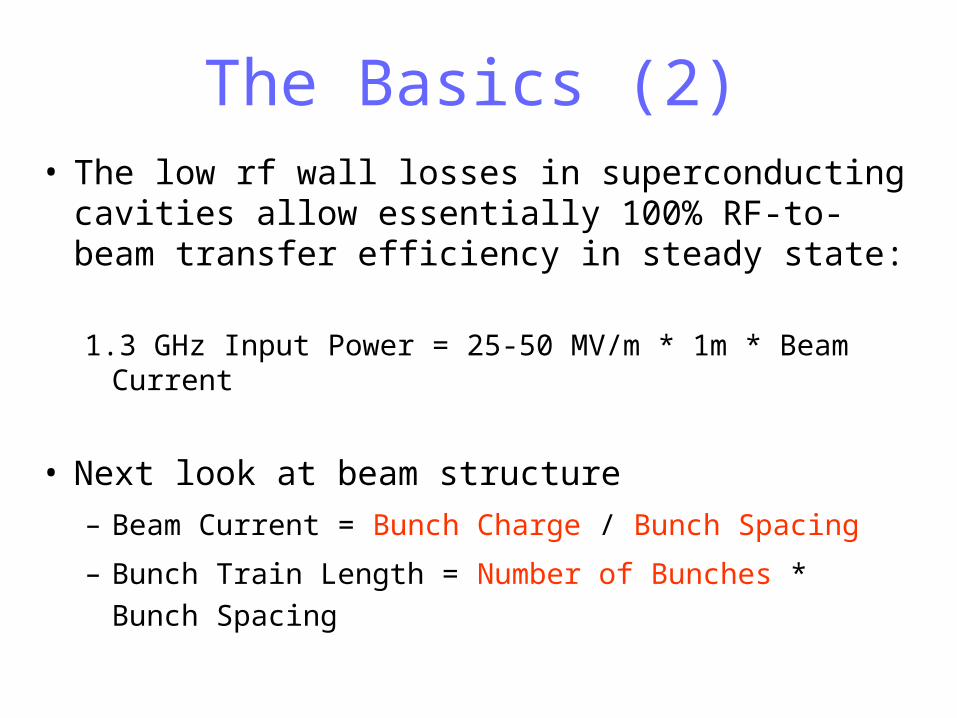
The Basics (2)• The low rf wall losses in superconducting cavities
allow essentially 100% RF-to-beam transfer efficiency in steady state:
1.3 GHz Input Power = 25-50 MV/m * 1m * Beam Current
• Next look at beam structure
– Beam Current = Bunch Charge / Bunch Spacing
– Bunch Train Length = Number of Bunches * Bunch
Spacing

Bunch Charge and Length• Nominal Bunch Charge (N = 2e10) and Length (z = 300
m)– Mainly determined by damping ring, linac energy spread and IP
considerations.• Bunch length reduced from 6 mm to 300 microns prior to
linac injection– Also constrained by
• Short-Range Transverse Wake Kicks (N z / a 3.5 )
• Short-Range Loading (N / z / a 2 )
Bunch
a
IrisRadius
Wakefield in a PETRA cavity

Number of Bunches per Pulse, Repetition Rate, Luminosity and AC
Power• Luminosity ~ Rep Rate Number of Bunches per
Pulse– Repetition rate (5 Hz) constrained by damping ring store
time (see next slide).
– Number of Bunches per Pulse constrained by • Train Length > Cavity Fill Time: for > 50% rf-to-beam efficiency,
minimum number of bunches is1870 (at 35 MV/m and 2e10 e/bunch) independent of bunch spacing !
• Length and cost of damping rings (newer, smaller designs assume smaller bunch separations).
• Train Length < Max klystron pulse length (limited by pulse heating).
– Product constrained by practical site power (few hundred MW). Would limit rep rate even damping rings did not.

• Optimal bunch train length very long (>> linac length), so – Minimize bunch spacing in the damping ring – limited by
separation (3-20 ns) required to extract individual bunches with a kicker magnet.
– Still, damping ring is long (17 km circumference in TDR, 6 km in current design), which makes the required store time long (200 ms), even with a few hundred meters of wigglers.
– RF pulse length (1.4 ms) << store time so ring needs to hold full bunch train.
– Store time limits machine repetition rate (5 Hz). Could increase wiggler length, but already about 20% of damping ring cost.
Damping Ring Constraints
Dog Bone Damping Ring

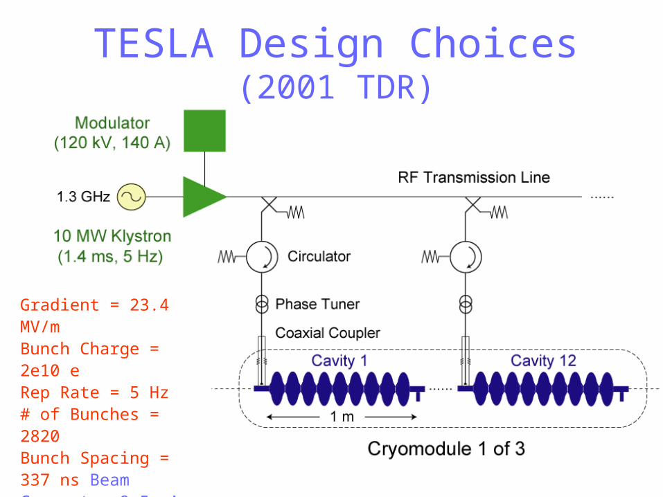
TESLA Design Choices(2001 TDR)
Gradient = 23.4 MV/mBunch Charge = 2e10 eRep Rate = 5 Hz# of Bunches = 2820Bunch Spacing = 337 ns Beam Current = 9.5 mAInput Power = 230 kWFill Time = 420 sTrain Length = 950 s

Bunch Spacing• Non-linac constraints on minimum spacing
– Peak positron target heating
– IP bunch separation
• Weak linac constraints
– Bunch coupling from long-range transverse wakefields
– Steady state RF-to-Beam efficiency: /Qo very high
(much different than for a warm machine)
• Strong linac constraints
– Power source costs ~ 1 / Bunch Spacing
– Cryogenic costs ~ Bunch Spacing

Klystron Economics• Cost of 1.3 GHz Klystron + Modulator (crude approximation)
– Similar for similar average power
– Independent of peak power.
• However, rf energy per pulse differs greatly, for example,
– 20 MW peak, 10 sec pulses (300 Hz, 60 kW)
– 5 MW peak, 2 msec pulses (10 Hz, 100 kW)
– 0.1 MW peak, CW
• Number of klystrons
~ Cavity Input Power / Peak Klystron Power
~ 1 / Bunch Spacing (with fixed peak power)
• With smaller bunch spacing, would not use full average klystron average power capability.

Bunch Spacing and Fill Time• Adjust Qext to match cavity impedance (R/Qo * Qext) to the beam
impedance (Gradient / Current). So Fill Time ~ Bunch Spacing
• For TDR parameters, Qext = 3e6 so cavity BW = 430 Hz.
• Need to achieve < 0.1% energy gain uniformity.

Coa
xial
Pow
er C
oupl
er
InputPower
Other Bunch Spacing Considerations
• Input coupler power limitations– Power ~ 1 / Bunch Spacing– Baseline TTF3 design processed to 1 MW and tested up to 600 kW
for 35 MV/m operation (1000 hours): long term reliability for required operation at 350 kW not known.
TESLA Design Choices(2001 TDR)
Gradient = 23.4 MV/mBunch Charge = 2e10 eRep Rate = 5 Hz# of Bunches = 2820Bunch Spacing = 337 ns Beam Current = 9.5 mAInput Power = 230 kWFill Time = 420 sTrain Length = 950 s
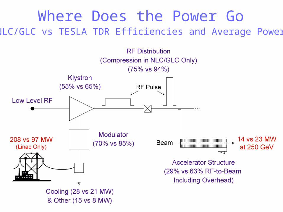
Where Does the Power Go(NLC/GLC vs TESLA TDR Efficiencies and Average Power)

Cost Optimization• Major cost components that depend on Gradient (G)
and Bunch Train Length (Tb).
Cooling + Power + Length
~ A Tb G + B Tb-1 + C G
-1
• Cost Study: Compute Cost vs G and Tb for fixed
Luminosity (L)
– Assume charge per bunch and number of bunches constant
– Cavity fill time (Tf) scales as G * Tb
– RF pulse length (Trf) = Tb + Tfill

* TPC is for 500 GeV machine in US Options Study but does not include additional unpowered tunnel sections.
20 25 30 35 40 45 50 55 600.98
1
1.02
1.04
1.06
1.08
1.1
1.12
1.14
1.16
1.18
1.2
Relative Total Project Cost* (TPC) -vs-
Linac Gradient
Gradient ( MV/m)
Rela
tive C
ost

Gradient ( MV/m)
Cryo Plant
Cost
(B
$)
Gradient ( MV/m)
20 30 40 50 600.1
0.2
0.3
0.4
0.5
0.6
0.7
0.8
20 30 40 50 600.2
0.3
0.4
0.5
0.6
0.7
0.8
0.9
Cryomodules
Contributions to TPC (One Linac)

400 600 800 1000 1200 14000.99
1
1.01
1.02
1.03
1.04
1.05
Rela
tive C
ost
Relative TPC -vs- Bunch Train Length
Bunch Train Length (us)
G = 35 MV/m
23.4 MV/m

0.1 0.2 0.3 0.4 0.5 0.6 0.7 0.8 0.9 10.92
0.94
0.96
0.98
1
1.02
1.04
Reduce Train Length
Rela
tive C
ost
Relative TPC -vs- Luminosity(35 MV/m, Fixed Bunch Charge, Linac Changes Only)
Reduce Beam Current
Reduce Rep Rate
Relative Luminosity
Part II: ILC Design Choices
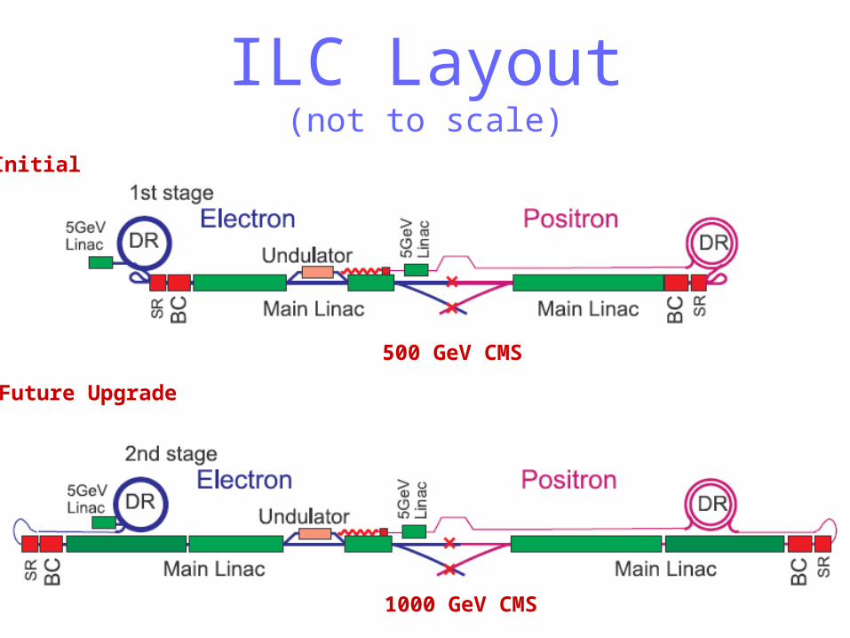
ILC Layout(not to scale)
1000 GeV CMS
Initial
Future Upgrade
500 GeV CMS
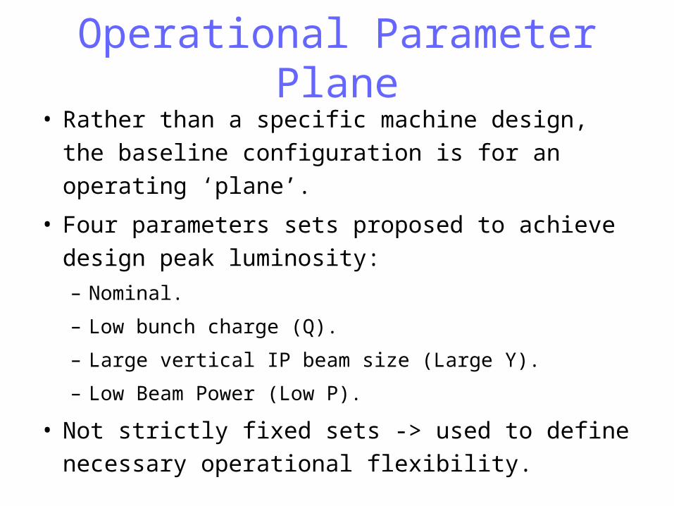
Operational Parameter Plane• Rather than a specific machine design, the
baseline configuration is for an operating ‘plane’.
• Four parameters sets proposed to achieve
design peak luminosity:
– Nominal.
– Low bunch charge (Q).
– Large vertical IP beam size (Large Y).
– Low Beam Power (Low P).
• Not strictly fixed sets -> used to define
necessary operational flexibility.

Parameter Planenominal low Q large Y low P
N 1010 2 1 2 2
nb 2820 5640 2820 1330
x,y m, nm 9.6, 40 10,30 12,80 10,35
x,y cm, mm 2, 0.4 1.2, 0.2 1, 0.4 1, 0.2
x,y nm 543, 5.7 495, 3.5 495, 8 452, 3.8
tb ns 308 154 308 462
BS % 2.2 1.8 2.4 5.7
z mm 300 150 500 200
Pbeam MW 11 11 11 5.3
L 1034 2 2 2 2
Main Linac Design• Baseline Configuration Document (BCD) distilled from
Snowmass Working Group recommendations in August
2005.
• Major differences from 2001 Tesla TDR 500 GeV Design.
– Higher gradient (31.5 MV/m instead of 23.4 MV/m) for cost
savings.
– Two tunnels (service and beam) instead of one for improved
availability.
• The Linac Area Group of the Global Design Effort (GDE)
is continuing to evolve design.

‣ For ILC, would accept only ‘vertically’ tested cavities (using CW rf without high
power couplers) that achieve gradients > 35 MV/m and Q > 8e9 (discard or
reprocess rejects).
‣ When installed in 8 cavity cryomodules, expect stable operation at an average
gradient of 31.5 MV/m and Q = 1e10 (rf system designed for 35 MV/m).
‣ Derating due to desire for overhead from quench limit, lower installed
performance and limitations from using a common rf source.
‣ For a 1 TeV upgrade, expect average gradient = 36 MV/m, Q = 1e10 for new
cavities (the TDR 800 GeV design assumed 35 MV/m and Q > 5e9).
1.3 GHz TESLA
Cavities

ILC Linac RF Unit (1 of ~ 600)
Gradient = 31.5 MV/mBunch Charge = 2e10 eRep Rate = 5 Hz# of Bunches = 2967Bunch Spacing = 337 ns Beam Current = 9.5 mAInput Power = 311 kWFill Time = 565 sTrain Length = 1000 s
(8 Cavities per Cryomodule)

Achieved Gradients in Single and 9-Cell Cavities• In recent years, single-cell cavity gradients approached fundamental limit:
Bc * (Grad / B surface) ~ 1800/41.5 ~ 43 MV/m for Tesla-shape cavities.
• During past 2.5 years, DESY has produced 6 fully-dressed cavities with Gradients > 35 MV/m and Q > 8e9. Yield for such cavities < 30%.
Test Results for Dressed-Cavities that will be used in a ’35 MV/m’ Cryomodule

Main Production Problem Has Been Poor Reproducibility
0
5
10
15
20
25
30
35
40
45
Jan-95 Jan-96 Jan-97 Jan-98 Jan-99 Jan-00 Jan-01 Jan-02 Jan-03 Jan-04 Jan-05 Jan-06
Eac
c[M
V/m
]
BCP
EP
10 per. Mov. Avg. (BCP)
10 per. Mov. Avg. (EP)
Gradients achieved over time in DESY cavities
ILC Goal

Achieved Gradients in Tesla Test Facility (TTF)
8-Cavity Cryomodules (Cavities not Electro-Polished)
Cryomodule Number
Gra
die
nt
(MV
/m)
Diamonds and Error Bars = Range of Gradients Achieved in Individual CW Cavity Tests.
= Average Gradient Achieved in Cryomodule

High Gradient R&D: Low Loss (LL) and Re-Entrant (RE) Cells with a Lower Bpeak/Eacc
Ratio

Fabricated at Cornell
Single Cell Results: Eacc = 47 - 52 MV/m
/Ichiro

CEBAF Single cell Chinese Large Grain Q0 vs. Eacc
1.00E+09
1.00E+10
1.00E+11
0 5 10 15 20 25 30 35 40
Eacc [MV/m]
Q0
Test#5a,after 1250C,3hrs,in situ baked
Test #2,no bake
Test#5,after 1250C,3 hrs, no bake Test #2/5/5a
Quench @ 36.6 MV/m
BCP + 120C Baking
Studies also underway using single or large grain Nb – could
eliminate need for Electro-Polishing (EP)

Tuning the Cavities• Both slow (500 kHz over minutes) and fast (2.5 kHz
during the 1.6 ms pulse) tuning required – achieve by compressing the cavity (~ 1 micron per 300 Hz).
• Want tuners located away from cavity ends to minimize cavity spacing.
• ‘Blade Tuner’ shown below. To date, have not achieved more than ~1kHz range of fast tuning. Final design for BCD not yet chosen.

RF Fill Dynamics• For ILC, Qext = 4e6 so cavity BW = 325 Hz (L = 1 micron).
• Need to achieve < 0.1% energy gain uniformity with Low Level RF
(LLRF) system
– Feedback to maintain constant ‘sum of fields’ in 24 cavities

Low Level RF Feedback Control

RF Distribution Math(for 35 MV/m Max Operation)
35 MV/m * 9.5 mA * 1.038 m = 345 kW (Cavity Input Power)× 24 Cavities× 1/.93 (Distribution Losses)× 1/.89 (Tuning Overhead)═ 10.0 MW
10 MW Klystron

Modulators (115 kV, 135 A, 1.5 ms, 5 Hz)
Pulse Transformer Style
(~ 2 m Long)
To generate pulse, an array of capacitors is slowly charged in parallel and then discharged in series using IGBT switches.
Will test full prototype in 2006

ILC BaselinePulse Transformer
Modulator
IGBT’s

Marx Generator Modulator
12 kV Marx Cell (1 of 16)
• IGBT switched• No magnetic core• Air cooled (no oil)

Modulators• Baseline: Pulse Transformer
– 10 units have been built over 10 years, 3 by FNAL and 7 by industry.
– 8 modulators in operation – no major reliability problems (DESY
continuing to work with industry on improvements).
– FNAL working on a more cost efficient and compact design, SLAC
building new dual IGBT switch.
• Alternative: Marx Generator
– Solid state, 1/n redundant modular design for inherent high
availability, reliability.
– Highly repetitive IGBT modules (90,000) cheap to manufacture.
– Eliminating transformer saves size, weight and cost, improves
energy efficiency.

SNS High Voltage Converter
Modulator (Unit installed at SLAC)RECTIFIER
TRANSFORMERAND FILTERS
SCRREGULATOR SWITCHING
BOOST TRANS-
FORMER
HV RECTIFIERAND FILTER NETWORK
13.8KV3Ø
INPUTLINE CHOKE
5th
HARMONICTRAP
7th
HARMONICTRAP
50mH
AØ
BØCØ
3Ø(ON/OFF)
4mH400A
4mH400A
6 EACH
6 EACH
RTNAØ BØ CØ
-HV -HV -HV 10ohm 20mH
.03uF
.03uF
.05uFVMON
HVOUTPUT
RECTIFIER TRANSFORMER
AND FILTERS
SCRREGULATOR
HVCMEQUIPMENT
CONTROL RACK
ENERGYSTORAGE
Other Alternativ
eModulator
s

Series Switch Modulator(Diversified Technologies, Inc. )
IGBT Series Switch
140kV, 500A switch shown at left in use at CPI
As a Phase II SBIR, DTI is building a 120 kV, 130 A version with a bouncer to be delivered to SLAC at the end of 2006
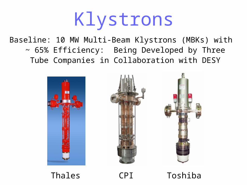
KlystronsBaseline: 10 MW Multi-Beam Klystrons (MBKs) with ~ 65%
Efficiency: Being Developed by Three Tube Companies in Collaboration with DESY
Thales CPI Toshiba

Status of the 10 MW MBKs• Thales: Four tubes produced, gun arcing problem occured and seemed
to be corrected in last two tubes after fixes applied (met spec). However,
tubes recently developed other arcing problems above 8 MW. Thales to
build two more without changes and two with changes after problem is
better diagnosed.
• CPI: One tube built and factory tested to 10 MW at short pulse. At DESY
with full pulse testing, it developed vacuum leak after 8.3 MW achieved –
has been repaired and will be tested again.
• Toshiba: One tube built and achieved operation spec but developed
arcing problems above 8 MW – being shipped to DESY for further
evaluation.
• These are vertically mounted tubes – DESY will soon ask for bids on
horizontally mounted tubes for XFEL (also needed for ILC).
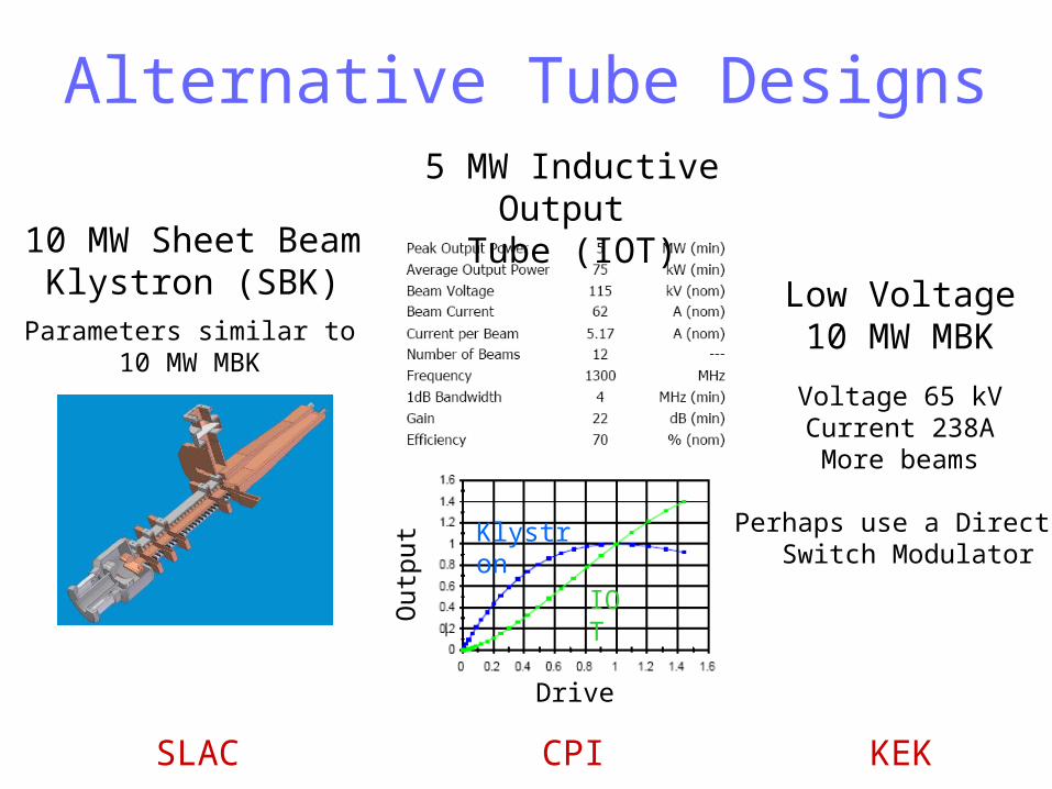
Alternative Tube Designs
10 MW Sheet BeamKlystron (SBK)Parameters similar to
10 MW MBK
Low Voltage10 MW MBK
Voltage 65 kVCurrent 238AMore beams
Perhaps use a Direct Switch Modulator
5 MW Inductive Output Tube (IOT)
Drive
Out
put
IOT
Klystron
SLAC CPI KEK
Klystron Summary• The 10 MW MBK is the baseline choice – continue to
support tube companies to make them robust (DESY needs
35 for XFEL although will run at 5 MW).
• SLAC funding design of a 10 MW sheet-beam klystron (will
take several years to develop).
• Backup 1: Thales 2104C 5 MW tube used at DESY and
FNAL for testing – it appear reliable (in service for 30 years)
but has lower effiency compared to MBKs (42% vs 65%).
• Backup 2: With increased DOE funding next year, propose
to contract tube companies to develop high efficiency,
single-beam, 5 MW klystron.

RF DistributionBaseline choice is the waveguide system used at TTF, which includes off-the-shelf couplers, circulators and 3-stub tuners (phase control).

Need more compact design (Each Cavity Fed 350 kW, 1.5 msec Pulses at 5 Hz)
Two of ~ 16,000 Feeds

Baseline
Alternative Design with No Circulators
And should consider simplifications(circulators are ~ 1/3 of cost)

C. Nantista
Adjustable Tap-Offs Using Mode Rotation
Rotatable section with central elliptical region, matched for both polarizations of circular TE11 mode with differing phase lengths.
rotatable joints
load
feed
1
2
3
4
mode rotator
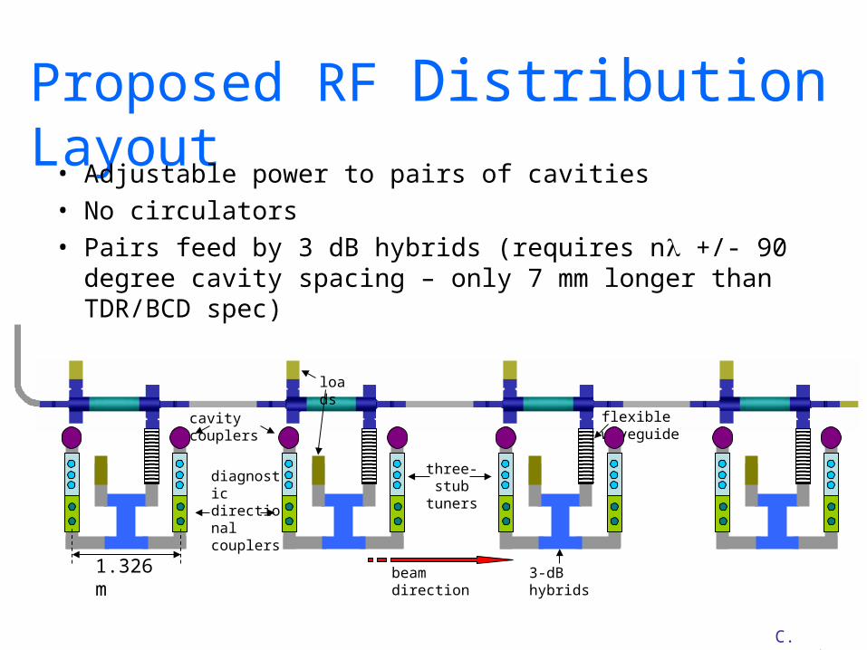
cavity couplers
diagnostic directional couplers
three-stub tuners
flexible waveguide
3-dB hybridsbeam direction
loads
C. Nantista
1.326 m
Proposed RF Distribution Layout
• Adjustable power to pairs of cavities• No circulators• Pairs feed by 3 dB hybrids (requires n +/- 90 degree
cavity spacing – only 7 mm longer than TDR/BCD spec)
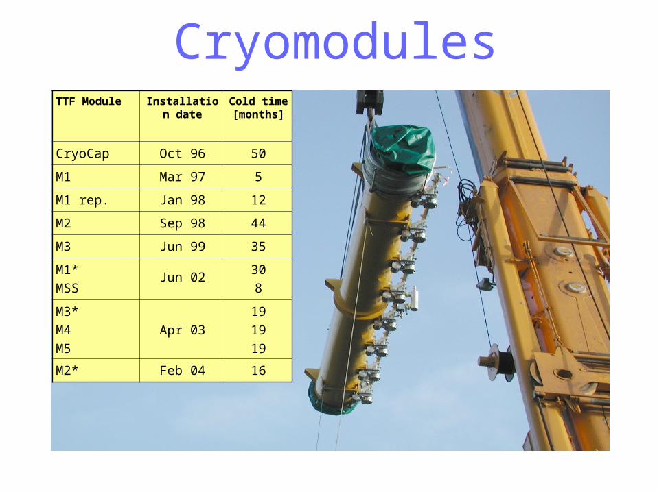
TTF Module Installation date
Cold time [months]
CryoCap Oct 96 50
M1 Mar 97 5
M1 rep. Jan 98 12
M2 Sep 98 44
M3 Jun 99 35
M1*
MSSJun 02
30
8
M3*
M4
M5
Apr 03
19
19
19
M2* Feb 04 16
Cryomodules
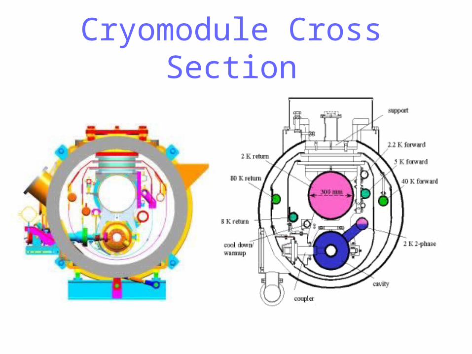
Cryomodule Cross Section

Multipacting Simulation of TTF3 Coupler
Bellows
Primaries -Green, Secondaries- RedPrimaries -Green, Secondaries- Red
“Cold Side”

Cryomodule DesignRelative to the TTF cryomodules
– Continue with 8 cavities per cryomodule based on experience and minimal cost savings if number increased (12 in TDR).
– Move quad / corrector / bpm package to center (from end) to improve stability.
– Increase some of cryogenic pipe sizes (similar to that proposed for the XFEL).
– Decrease cavity separation from 344 mm to 283 mm as proposed in the TDR.
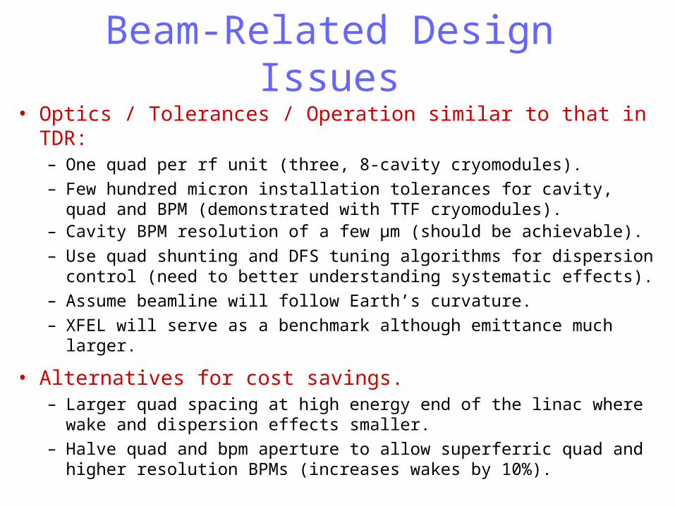
Beam-Related Design Issues• Optics / Tolerances / Operation similar to that in TDR:
– One quad per rf unit (three, 8-cavity cryomodules). – Few hundred micron installation tolerances for cavity, quad and BPM
(demonstrated with TTF cryomodules).– Cavity BPM resolution of a few μm (should be achievable).
– Use quad shunting and DFS tuning algorithms for dispersion control (need to better understanding systematic effects).
– Assume beamline will follow Earth’s curvature.– XFEL will serve as a benchmark although emittance much larger.
• Alternatives for cost savings.– Larger quad spacing at high energy end of the linac where wake and
dispersion effects smaller.– Halve quad and bpm aperture to allow superferric quad and higher
resolution BPMs (increases wakes by 10%).

Quad / Corrector / BPM Package
TDR
ILC Proposal
887 mm
77
66666 mm
78
BP
M Quad andCorrectors

Quad / Corrector / BPM Package
Al Cylinder
Iron YokeBlock
SC Coils
S-Band BPM Design(36 mm ID, 126 mm OD)
Dipole Design: Flux density and Flux Lines
SC ‘Cos(2)’ Quadrupole Magnet
1 10 100 1000
100
10
1
0.1
Frequency (Hz)
Inte
gra
ted
RM
S M
otio
n (n
m)
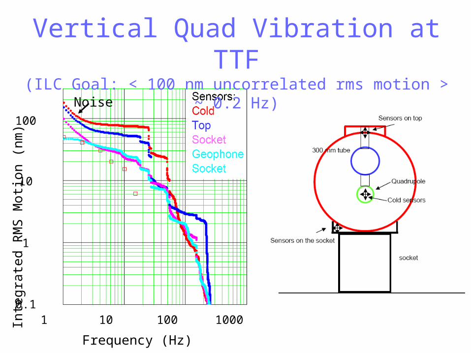
Vertical Quad Vibration at TTF(ILC Goal: < 100 nm uncorrelated rms motion > ~ 0.2 Hz)
Noise

Vertical Displacements of Cryomodule4 and 5 after Cooldown Relative to
Positions Just Prior to Cooldown
EPAC04

Alternative Quad Location
Cavity CavityQuad
CavityCavity Quad
Alternative
TTF

S-Band BPM Triplet Results(0.8 micron resolution, 1.4e10 electrons, Q of 500 for clean bunch separation)

TESLA cryogenic unit
Assume static heat leaks based on TTF measurements instead of the smaller values assumed in the TDR
Cryogenic System To Cryoplant

Cryoplant LayoutFor ILC 500, require 57 MW of AC power for Cryoplants

For baseline, developing deep underground (~100 m) layout with 4-5 m diameter tunnels spaced by 5 m.
ILC Tunnel Layout
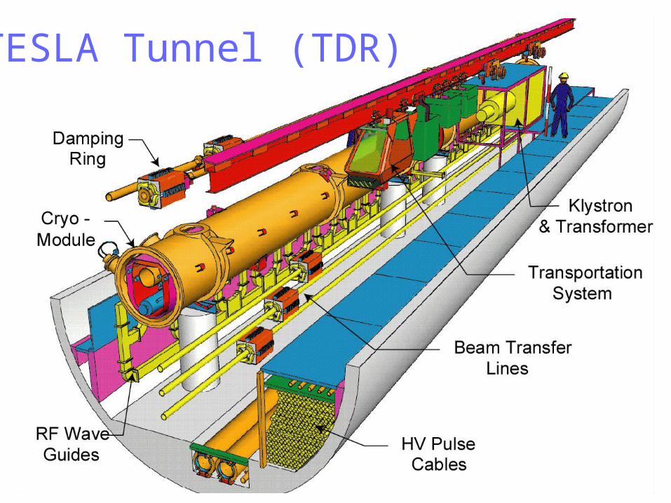
TESLA Tunnel (TDR)

ILC Availability Challenge
• The ILC will be an order of magnitude more complex
than any accelerator ever built.
• If it is built like present HEP accelerators, it will be
down an order of magnitude more (essentially
always down).
• For reasonable uptime, component availability must
be much better than ever before. Must do R&D and
budget for it up-front.
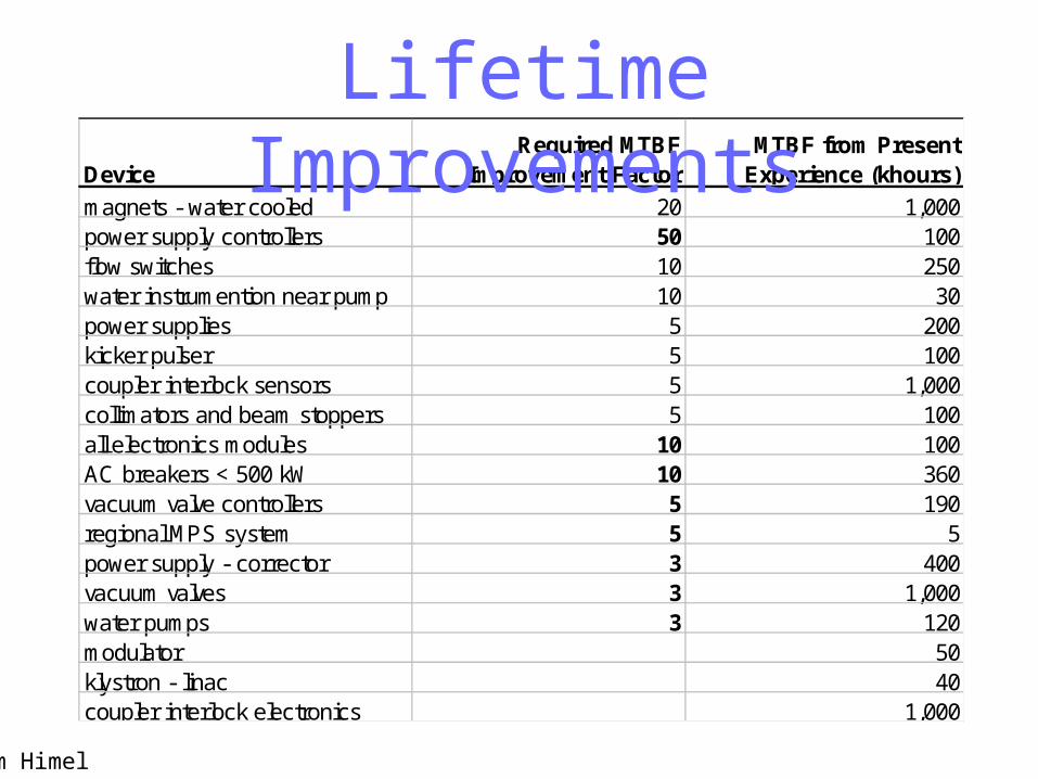
DeviceRequired MTBF
Improvement FactorMTBF from Present
Experience (khours)
magnets - water cooled 20 1,000power supply controllers 50 100flow switches 10 250water instrumention near pump 10 30power supplies 5 200kicker pulser 5 100coupler interlock sensors 5 1,000collimators and beam stoppers 5 100all electronics modules 10 100AC breakers < 500 kW 10 360vacuum valve controllers 5 190regional MPS system 5 5power supply - corrector 3 400vacuum valves 3 1,000water pumps 3 120modulator 50klystron - linac 40coupler interlock electronics 1,000
Lifetime Improvements
Tom Himel
SC Linac Summary• A superconducting linac allows for efficient
acceleration – for the ILC with a 35 MV/m gradient,
– 60% RF-to-Beam Efficiency
– 15% AC-to-Beam Efficiency
• A low beam current is required to make this approach
cost competitive (matches rf source capabilities).
• The resulting long bunch trains require large damping
rings with untested designs.

ILC Design Summary• Basic linac design complete: converging on details
– Tradeoffs of operability, availability and cost.
• Major cost and technical risks– Producing cryomodules that meet design gradient at a reasonable
cost (cost model still in development, XFEL will provide a reference, and will get new industry-based estimates).
– Producing a robust 10 MW klystron.
• Potential Cost Savings– Adopt Marx Modulator– Use simpler rf distribution scheme– Have one tunnel although ‘the additional cost is marginal when
considering the necessary overhead and equipment improvements to comply with reliability and safety issues.’
– Reduce cavity aperture to 60 mm for 21% reduction in dynamic cryo-loading and 16% reduction in cavity fill time.