URK-700 Service Manual 200703 - Frank's Hospital...
64
SERVICE MANUAL AURO REF / KERATOMETER URK-700 Revision 1.01 UNICOS Co., Ltd. www.e-unicos.com Before use this instrument, be sure to read this manual collectively.
Transcript of URK-700 Service Manual 200703 - Frank's Hospital...
SERVICE MANUAL
AURO REF / KERATOMETER URK-700
Revision 1.01 UNICOS Co., Ltd. www.e-unicos.com
Before use this instrument, be sure to read this manual collectively.

ⅰ
CONTENTS
1. General1.1 Features ········································································································ ····· 1
1.2 Dimensions ···································································································· ····· 2
2. Operational Description2.1 Measurement Principle2.1.1 Refractometry ······································································································ 3
2.1.2 Keratometry ···························································································· ············· 4
2.2 Layout of Optical System ················································································ 6
2.3 Electrical System2.3.1 Block Diagram ························································································ ·············· 8
2.3.2 Electrical Wiring ································································································ 9
2.3.3 Eyeball Diagram Generated by the REF Measurement ················································· 10
3. Repair Guide3.1 Disassembly and Adjustments3.1.1 Disassembling of Covers ·······················································································11
3.1.2 Disassembling of LCD module··············································································· ·· 13
3.1.3 Disassembling of Main PCB ···························································· ························ 13
3.1.4 Disassembling of Optical head assembly ································································ 14
3.1.5 Disassembling of Printer ····················································································· 15
3.1.6 Disassembling of SMPS ··············································································· ··········· 16
3.1.7 Disassembling of Headrest ···················································································· 17
3.1.8 Slit and photosensor Space Adjustment ·································································· 18
3.2 Calibration3.2.1 Refractometry calibration ·············································································· ······ 19
3.2.2 Keratometry calibration ······················································································· 24
4. SERVICE PARTS LIST4.1 OPTICAL HEAD ASS’Y ························································································· 29
4.2 LOWER BASE ASS’Y ···························································································· 29

1
4.3 JOYSTICK ASS’Y ························································································ ········ 29
4.4 UPPER BASE ASS’Y ························································································ ···· 29
4.5 COVER ASS’Y ····································································································· 30
4.6 HEADREST ASS’Y ································································································ 30
4.7 ACCESSORY ASS’Y ······························································································31
1
1. General
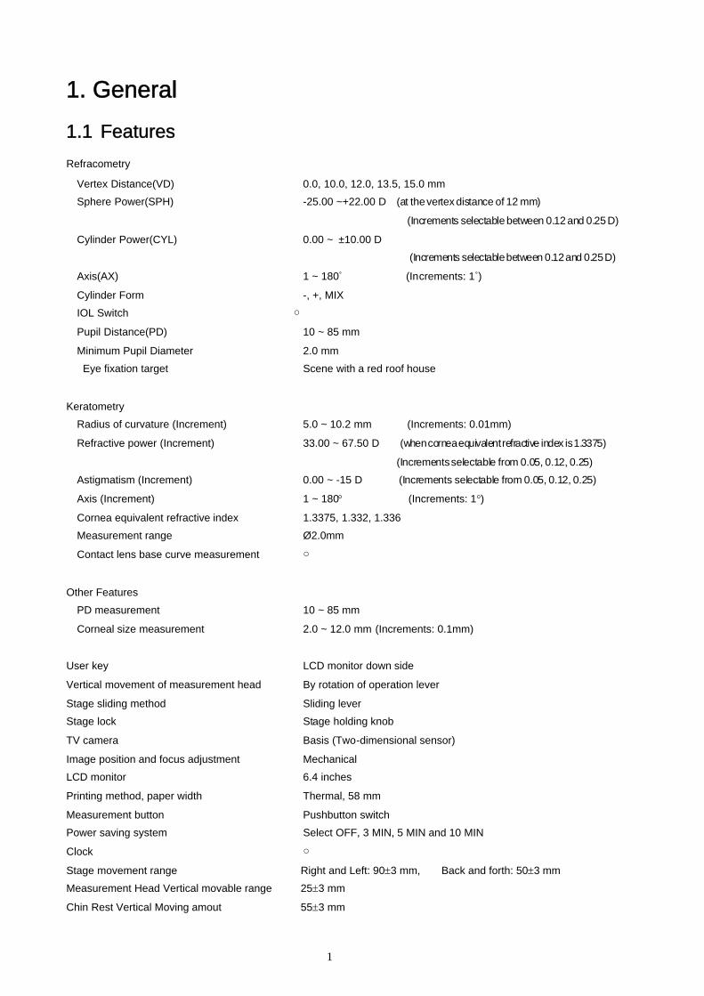
1.1 FeaturesRefracometry
Vertex Distance(VD) 0.0, 10.0, 12.0, 13.5, 15.0 mm
Sphere Power(SPH) -25.00 ~+22.00 D (at thevertex distance of 12 mm)
(Increments selectable between 0.12 and 0.25 D)
Cylinder Power(CYL) 0.00 ~ ±10.00 D
(Increments selectablebetween 0.12and 0.25D)
Axis(AX) 1 ~ 180˚ (Increments: 1 )̊
Cylinder Form -, +, MIX
IOL Switch ○
Pupil Distance(PD) 10 ~ 85 mm
Minimum Pupil Diameter 2.0 mm
Eye fixation target Scene with a red roof house
Keratometry
Radius of curvature (Increment) 5.0 ~ 10.2 mm (Increments: 0.01mm)
Refractive power (Increment) 33.00 ~ 67.50 D (whencorneaequivalentrefractive index is1.3375)
(Incrementsselectable from 0.05, 0.12, 0.25)
Astigmatism (Increment) 0.00 ~ -15 D (Increments selectable from 0.05, 0.12, 0.25)
Axis (Increment) 1 ~ 180 (Increments: 1)
Cornea equivalent refractive index 1.3375, 1.332, 1.336
Measurement range Ø2.0mm
Contact lens base curve measurement ○
Other Features
PD measurement 10 ~ 85 mm
Corneal size measurement 2.0 ~ 12.0 mm (Increments: 0.1mm)
User key LCD monitor down side
Vertical movement of measurement head By rotation of operation lever
Stage sliding method Sliding lever
Stage lock Stage holding knob
TV camera Basis (Two-dimensional sensor)
Image position and focus adjustment Mechanical
LCD monitor 6.4 inches
Printing method, paper width Thermal, 58 mm
Measurement button Pushbutton switch
Power saving system Select OFF, 3 MIN, 5 MIN and 10 MIN
Clock ○
Stage movement range Right and Left: 903 mm, Back and forth: 503 mm
Measurement Head Vertical movable range 253 mm
Chin Rest Vertical Moving amout 553 mm

2
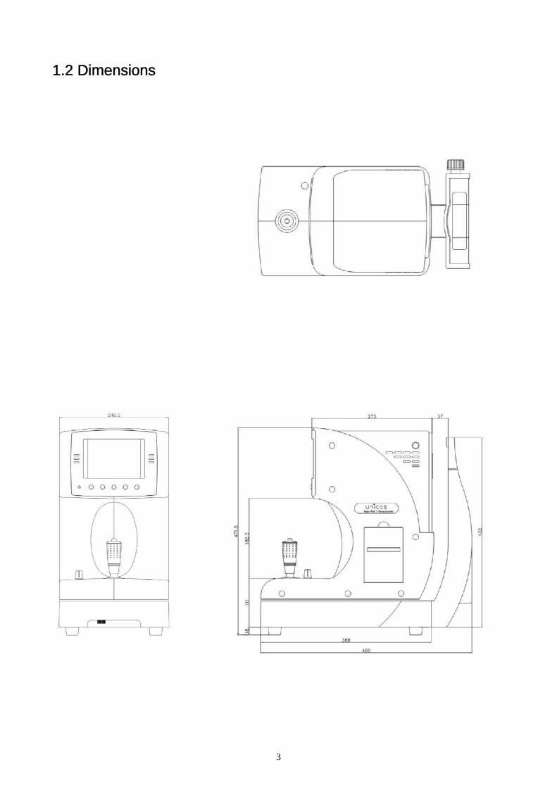
Dimension 248(W) 476(D) 475(H) mm
Weight Approximately 21 kg
3
1.2 Dimensions

4
2. Operational Description2.1 Measurement Principle2.1.1 Refractometry(1) A ray of light from the light source is reflected in the retina of examinee.
(2) According to refraction of examinee’s eye, the reflected light in the examinee’s eye exits as follow.
1) In case of emmetropia, the ray of light is parallel.
2) In case of near-sightedness, the ray of light is convergence.
3) In case of a farsighted eye, the ray of light is divergence.
(3) Then, the ray of light through the optical system imaged in the camera as six spot.
(4) Calculate the distance of coordinate of six spots and the center, obtain SPH, CYL and AX value.
Objective LensAperture
Light source
For measurementDivision pattern
CCD Camera
Myopia
Emmetropia
Hyperopia
α
Long axis
Short axis
0D
-D
+D

5
2.1.2 Keratometry
Mire Light is reflected examinee’s cornea, is imaged on the camera after through the Optical System.
Circular Mire Light is reflected circular or ellipse form by Radius of curvature and Astigmia of Examinee
cornea, coordinates of refracted light (XY Coordinates) on the camera is inputted the MPU, calculate that
data and obtain the Radius of Circle or the major axis and the minor axis of ellipse, Angle of Rotation .
R, θand h are correlated Snell’s Low as follows (R is radius of curvature of cornea, θ is incident angle
of Mire Light in the cornea, h is distance between position of Mire Light image at the cornea and Optical
Axis), obtain the long or short radius of curvature of cornea by this formula.
hR =
sin(θ/2)
θ/2
θ/2θ
θ/2 h
Optical Axis
R
Y
X
X2 Y2
a2+
b2= R
The major axisThe minor axis
θ
2b2a
Mire Light Source
Objective Lens for Keratoscope
Observational LensAperture for measuring
CCD Camera
θ/2
θ/2θ
θ/2 h
Optical Axis
R
Y
X
X2 Y2
a2+
b2= R
The major axisThe minor axis
θ
2b2a

6
R, D and n are correlated as follows (R is radius of curvature of cornea, D is refractive power of the cornea,
n is refractive index of the cornea), obtain the diopter(D) of cornea by R, long or short radius of curvature
of the cornea..
1000 (n-1)D =R(mm) Cornea equivalent refractive index n = 1.3375 , 1.336 ,
7
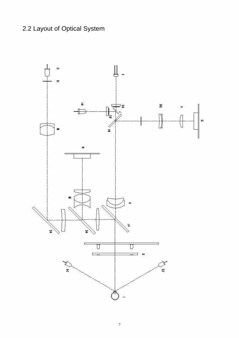
2.2 Layout of Optical System
8
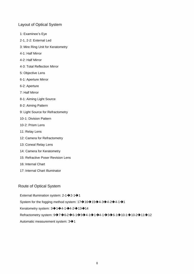
Layout of Optical System
1: Examinee’s Eye
2-1, 2-2: External Led
3: Mire Ring Unit for Keratometry
4-1: Half Mirror
4-2: Half Mirror
4-3: Total Reflection Mirror
5: Objective Lens
6-1: Aperture Mirror
6-2: Aperture
7: Half Mirror
8-1: Aiming Light Source
8-2: Aiming Pattern
9: Light Source for Refractometry
10-1: Division Pattern
10-2: Prism Lens
11: Relay Lens
12: Camera for Refractometry
13: Coneal Relay Lens
14: Camera for Keratometry
15: Refractive Poser Revision Lens
16: Internal Chart
17: Internal Chart Illuminator
Route of Optical System
External illumination system: 2-12-11
System for the fogging method system: 1716154-34-24-11
Keratometry system: 314-14-21314
Refractometry system: 976-26-154-114-156-110-110-21112
Automatic measurement system: 31
9
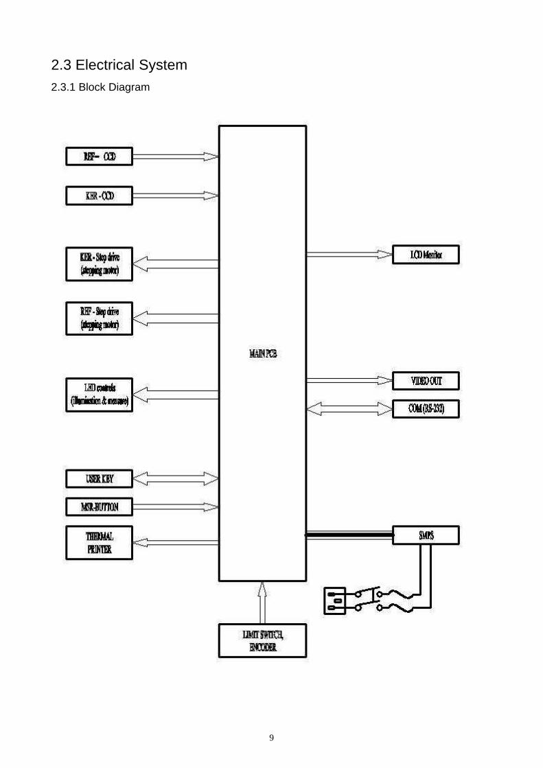
2.3 Electrical System2.3.1 Block Diagram

10
2.3.2 Electrical Wiring
11
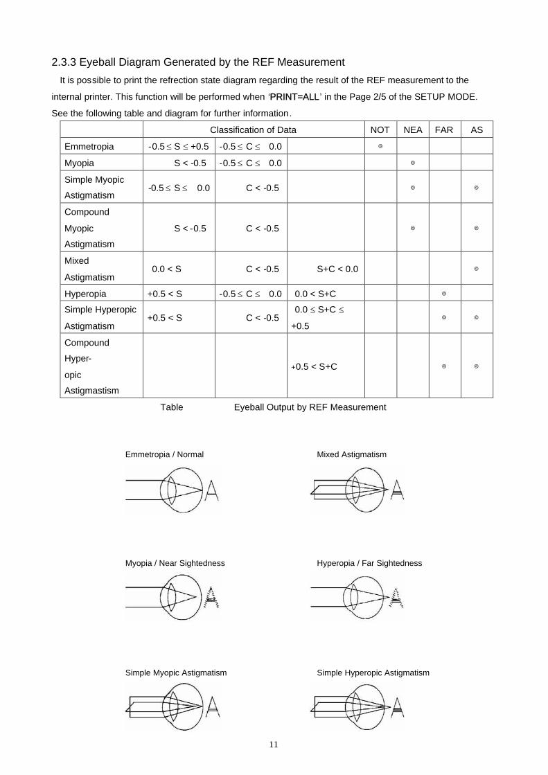
2.3.3 Eyeball Diagram Generated by the REF MeasurementIt is possible to print the refrection state diagram regarding the result of the REF measurement to the
internal printer. This function will be performed when ‘PRINT=ALL’ in the Page 2/5 of the SETUP MODE.
See the following table and diagram for further information.
Classification of Data NOT NEA FAR AS
Emmetropia -0.5 S +0.5 -0.5 C 0.0 ◎
Myopia S < -0.5 -0.5 C 0.0 ◎
Simple Myopic
Astigmatism-0.5 S 0.0 C < -0.5 ◎ ◎
Compound
Myopic
Astigmatism
S < -0.5 C < -0.5 ◎ ◎
Mixed
Astigmatism0.0 < S C < -0.5 S+C < 0.0 ◎
Hyperopia +0.5 < S -0.5 C 0.0 0.0 < S+C ◎
Simple Hyperopic
Astigmatism+0.5 < S C < -0.5
0.0 S+C
+0.5◎ ◎
Compound
Hyper-
opic
Astigmastism
+0.5 < S+C ◎ ◎
Table Eyeball Output by REF Measurement
Emmetropia / Normal Mixed Astigmatism
Myopia / Near Sightedness Hyperopia / Far Sightedness
Simple Myopic Astigmatism Simple Hyperopic Astigmatism
12
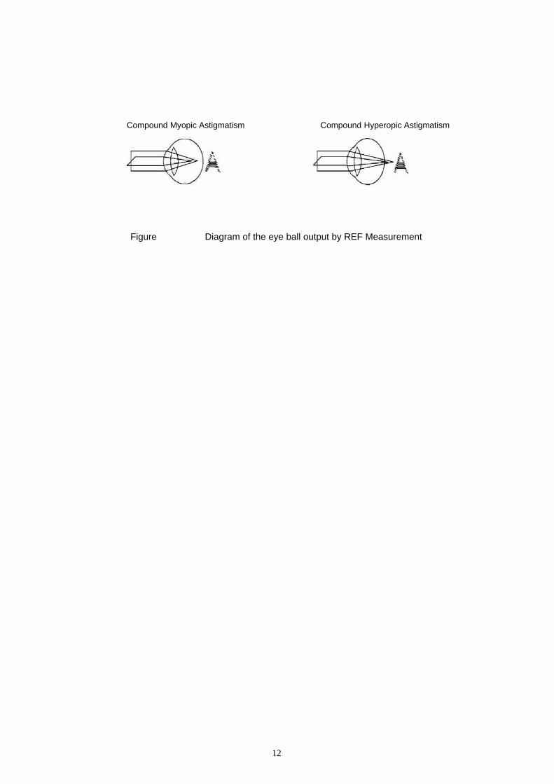
Compound Myopic Astigmatism Compound Hyperopic Astigmatism
Figure Diagram of the eye ball output by REF Measurement
11
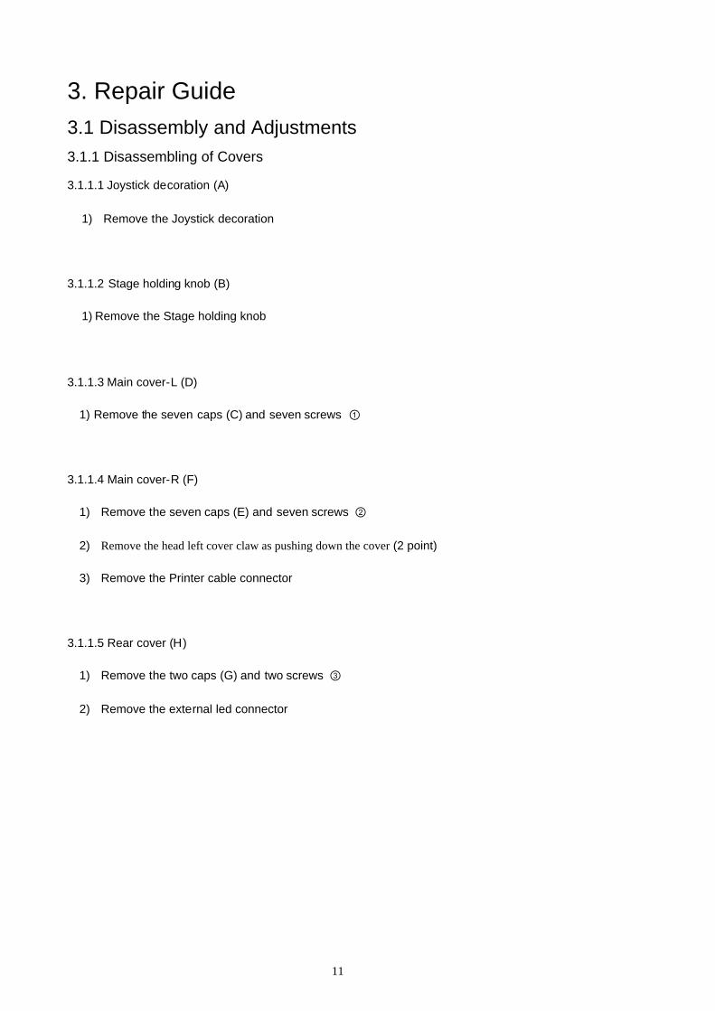
3. Repair Guide3.1 Disassembly and Adjustments3.1.1 Disassembling of Covers
3.1.1.1 Joystick decoration (A)
1) Remove the Joystick decoration
3.1.1.2 Stage holding knob (B)
1) Remove the Stage holding knob
3.1.1.3 Main cover-L (D)
1) Remove the seven caps (C) and seven screws ①
3.1.1.4 Main cover-R (F)
1) Remove the seven caps (E) and seven screws ②
2) Remove the head left cover claw as pushing down the cover (2 point)
3) Remove the Printer cable connector
3.1.1.5 Rear cover (H)
1) Remove the two caps (G) and two screws ③
2) Remove the external led connector

12
13
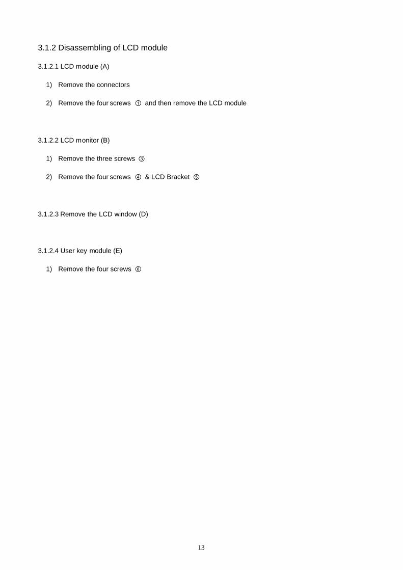
3.1.2 Disassembling of LCD module
3.1.2.1 LCD module (A)
1) Remove the connectors
2) Remove the four screws ① and then remove the LCD module
3.1.2.2 LCD monitor (B)
1) Remove the three screws ③
2) Remove the four screws ④ & LCD Bracket ⑤
3.1.2.3 Remove the LCD window (D)
3.1.2.4 User key module (E)
1) Remove the four screws ⑥

14
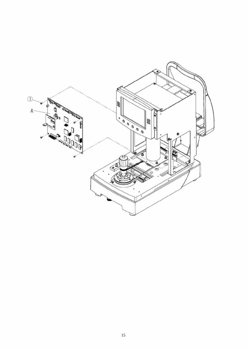
3.1.3 Disassembling of main PCB (A)
1) Remove the connectors
2) Remove the four screws ① and then remove the main PCB
15
16
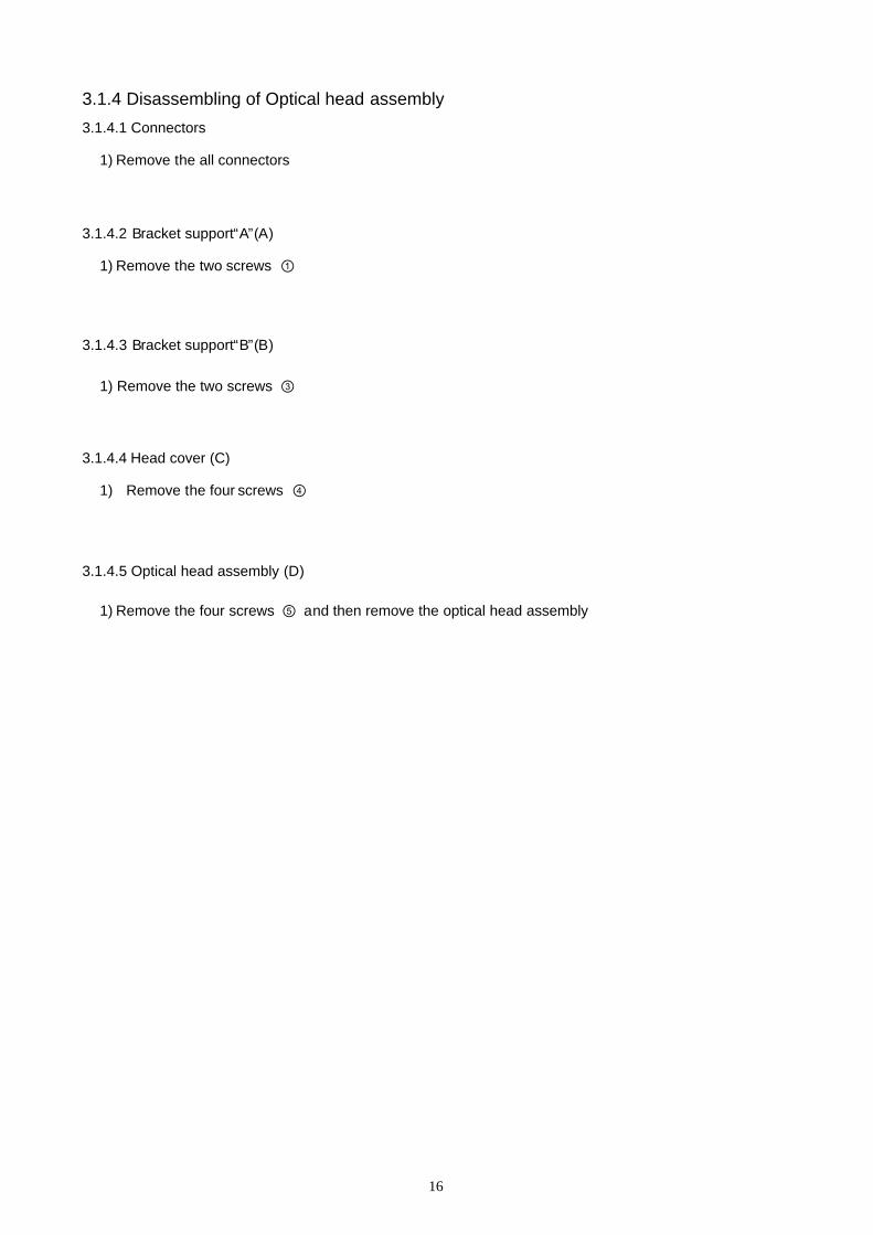
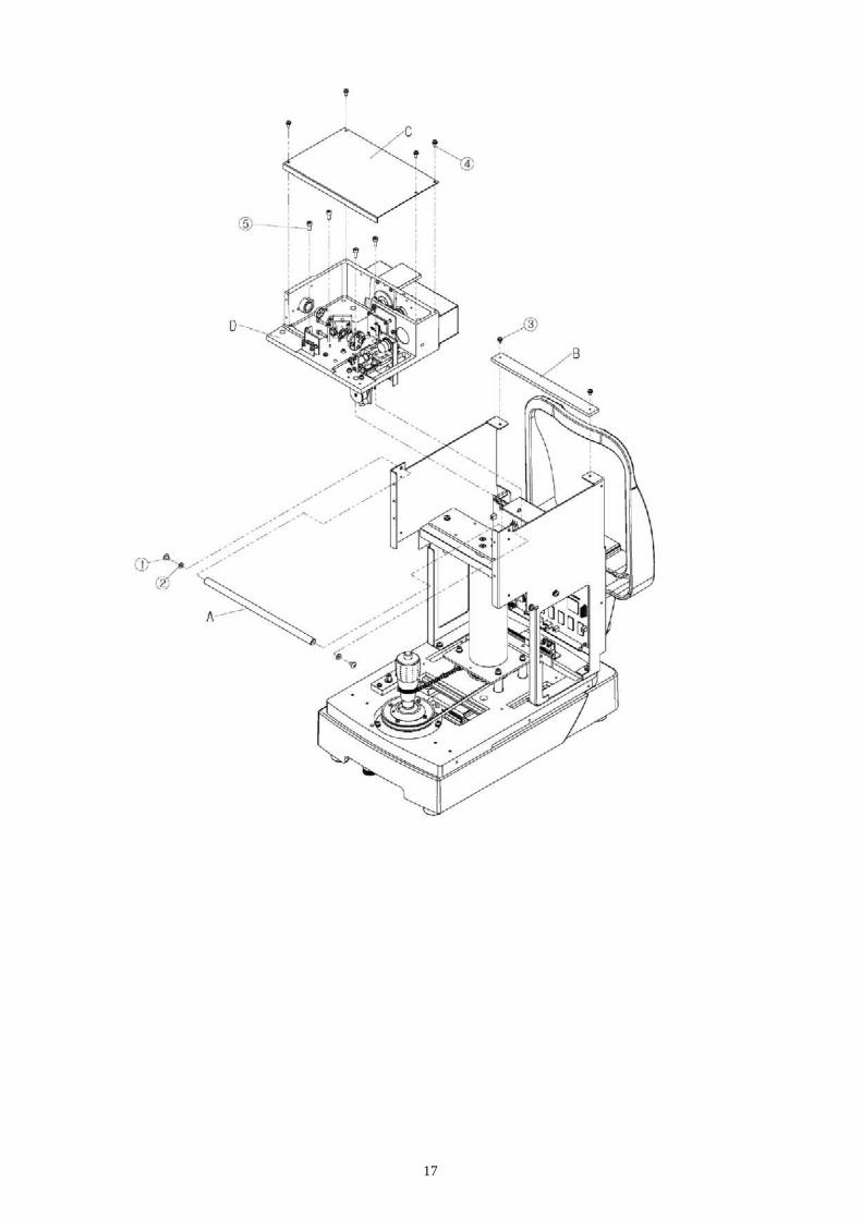
3.1.4 Disassembling of Optical head assembly3.1.4.1 Connectors
1) Remove the all connectors
3.1.4.2 Bracket support“A”(A)
1) Remove the two screws ①
3.1.4.3 Bracket support“B”(B)
1) Remove the two screws ③
3.1.4.4 Head cover (C)
1) Remove the four screws ④
3.1.4.5 Optical head assembly (D)
1) Remove the four screws ⑤ and then remove the optical head assembly
17

18
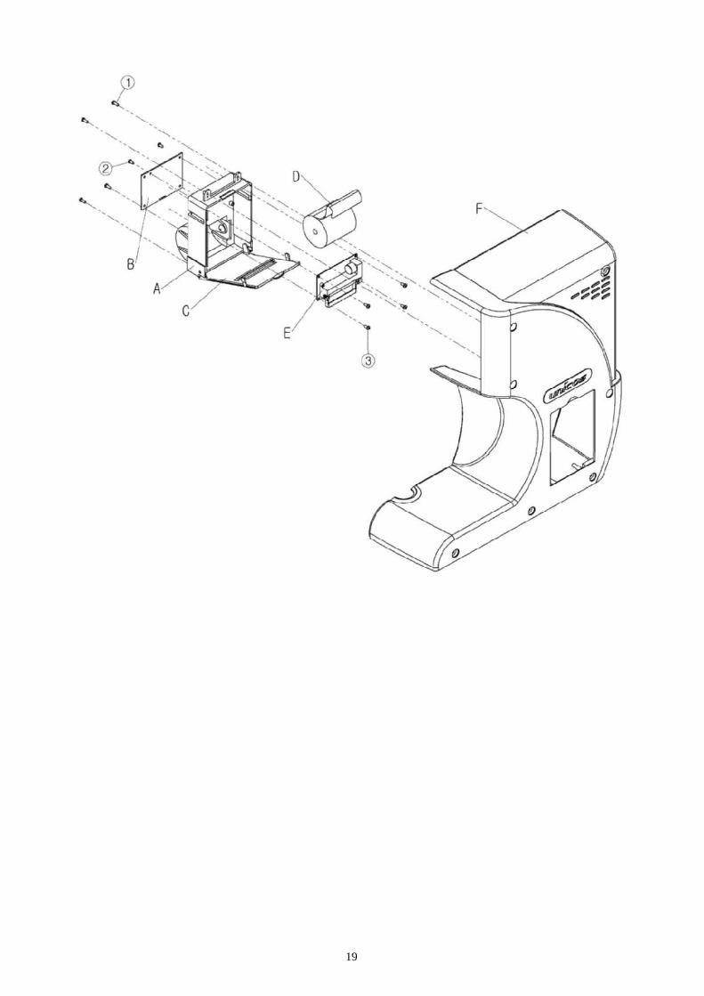
3.1.5 Disassembling of printer3.1.5.1 Printer assembly (A)
1) Remove the four screws ① and then remove the printer assembly
3.1.5.2 Printer PCB (B) & printer cable
1) Remove the four screws ②
2) Carefully remove FPC connector from PCB (B)
3.1.5.3 Open the printer door (C)
3.1.5.4 Remove the Printer Roll (F) and Printer Paper (D)
3.1.5.4 Thermal printer (E)
1) Remove the four screws ③
19

20
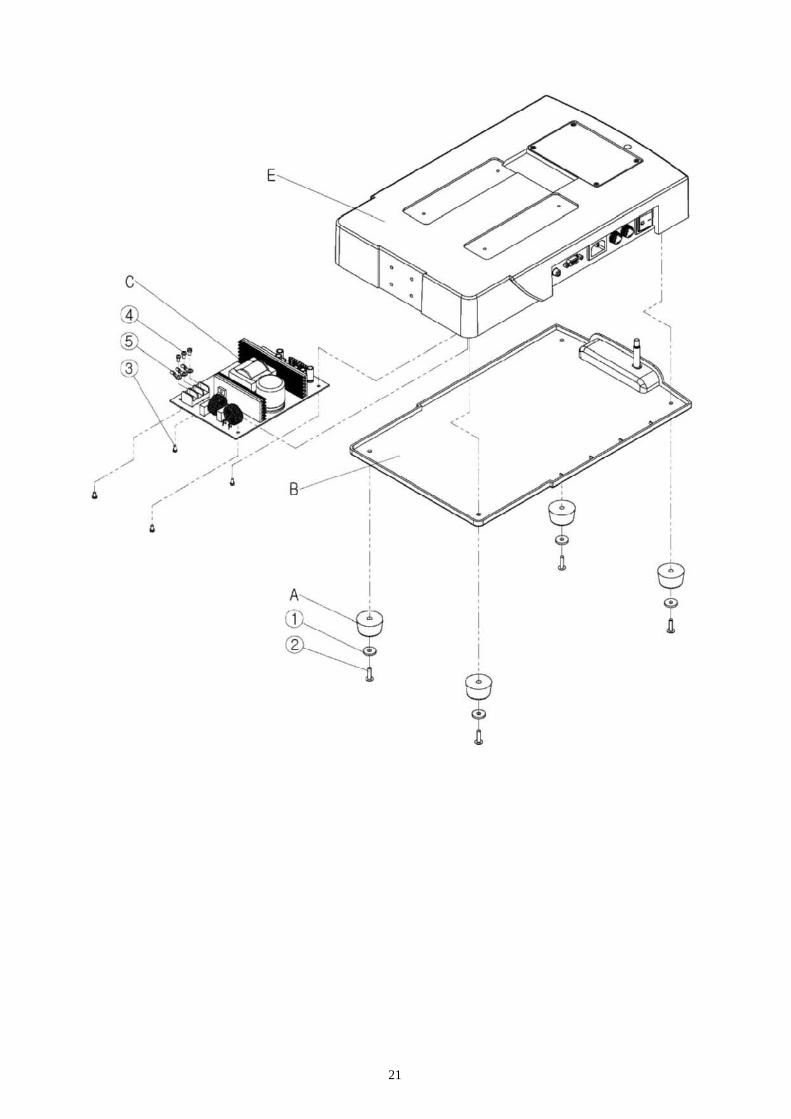
3.1.6 Disassembling of SMPS3.1.6.1 Base cover (A)
1) Remove the four screws ① and then remove the four foots(A)
3.1.6.2 SMPS (B)
1) Remove the four screws ③
2) Remove the connector
3) Remove the three screws ④
21

22
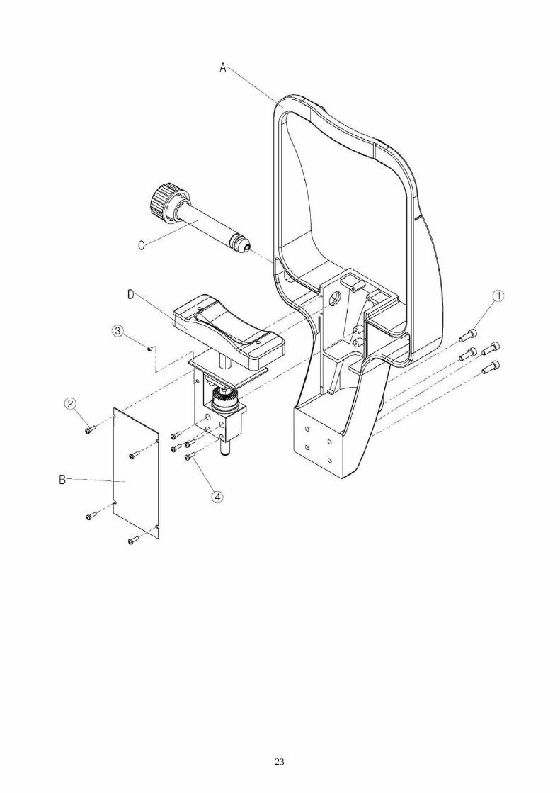
3.1.7 Disassembling of headrest3.1.7.1 Headrest assembly (A)
1) Remove the four screws ① and then remove the headrest assembly
3.1.7.2 Headrest body cover (B)
1) Remove the four screws ②
3.1.7.3 Knob gear assembly (C)
1) Remove the setscrew ③ and then remove the knob gear assembly
3.1.7.4 Headrest body assembly (D)
1) Remove the four screws ④ and then remove the headrest body assembly.
23
24
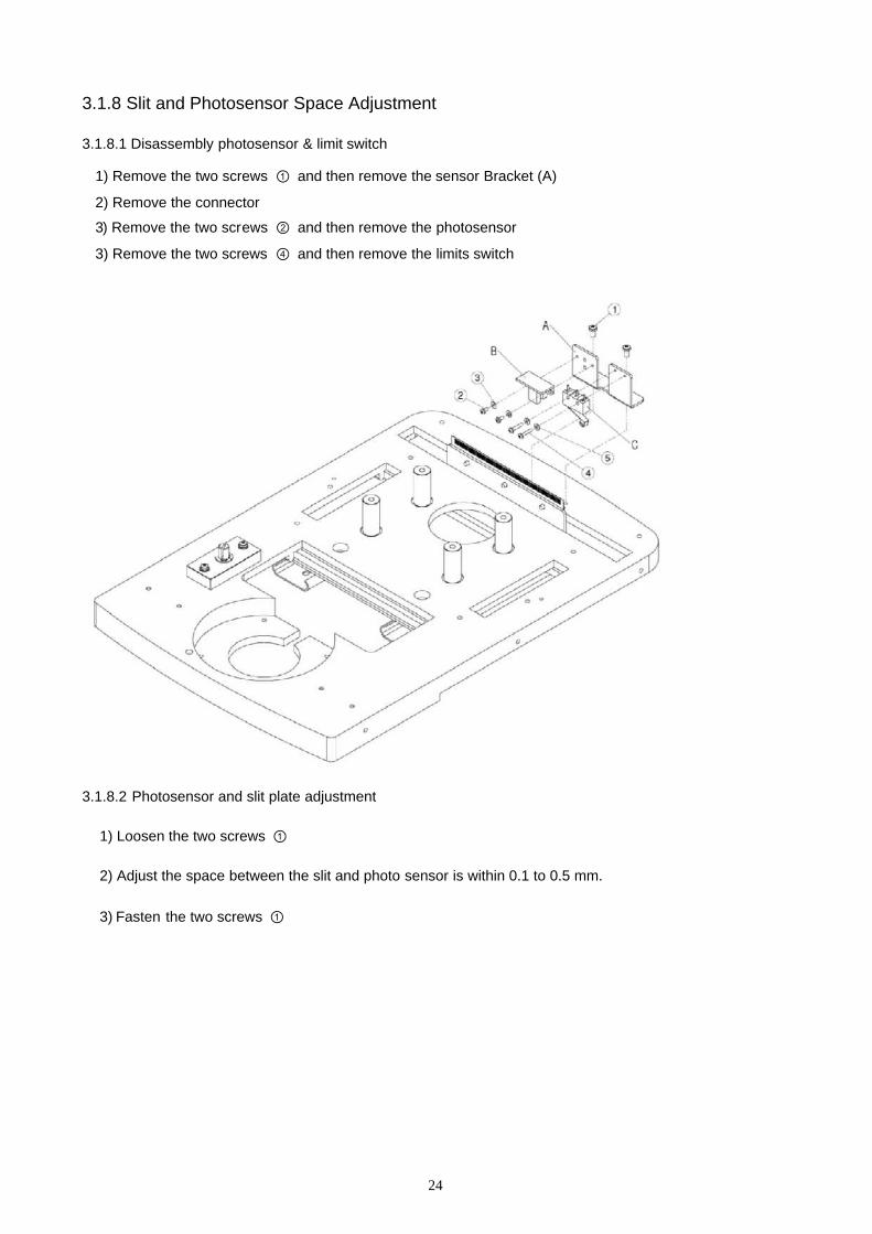
3.1.8 Slit and Photosensor Space Adjustment
3.1.8.1 Disassembly photosensor & limit switch
1) Remove the two screws ① and then remove the sensor Bracket (A)
2) Remove the connector
3) Remove the two screws ② and then remove the photosensor
3) Remove the two screws ④ and then remove the limits switch
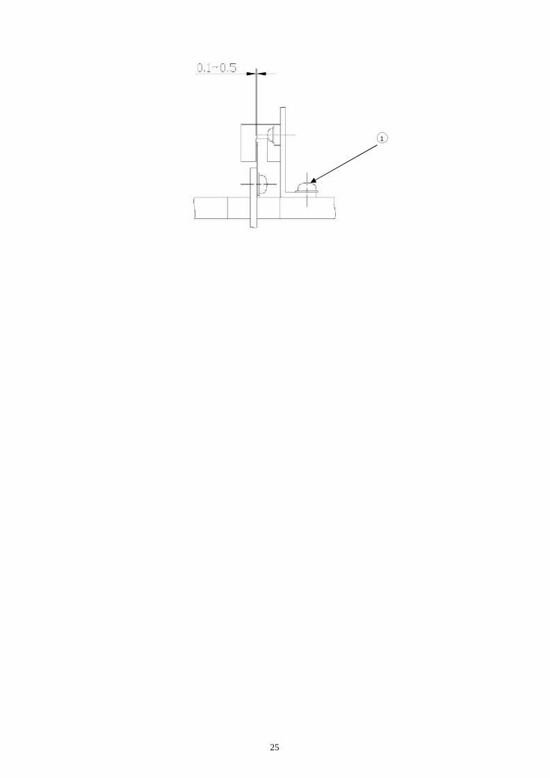
3.1.8.2 Photosensor and slit plate adjustment
1) Loosen the two screws ①
2) Adjust the space between the slit and photo sensor is within 0.1 to 0.5 mm.
3) Fasten the two screws ①
25
1

26
3.2 Calibration
3.2.1 Refractometry calibration
(1) Purpose
To refractometry calibration after refractometry CCD camera adjustment,etc.
(2) Units
1) Model eye lens adapter
2) Spherical model eye lens(-20D ~ +20D)
(3) Preparation
1) Attach model eye lens adapter to head base.
2) Insert Unit ② in Unit ①.
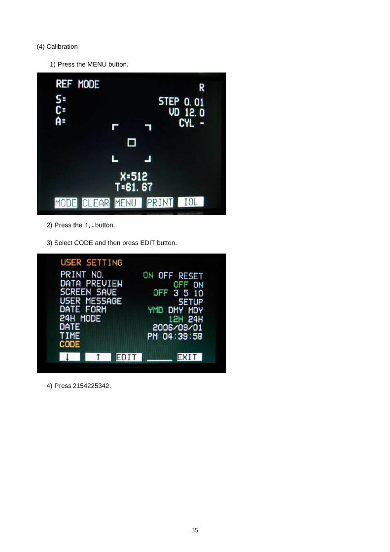
(4) Calibration
1) Press the MENU button.
Head base
①
②

27
2) Press the ↑,↓button.
3) Select CODE and then press EDIT button.
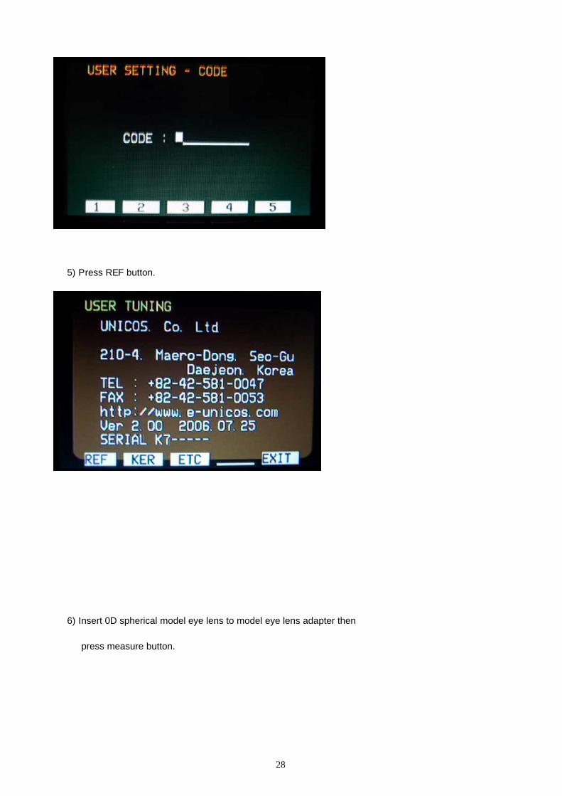
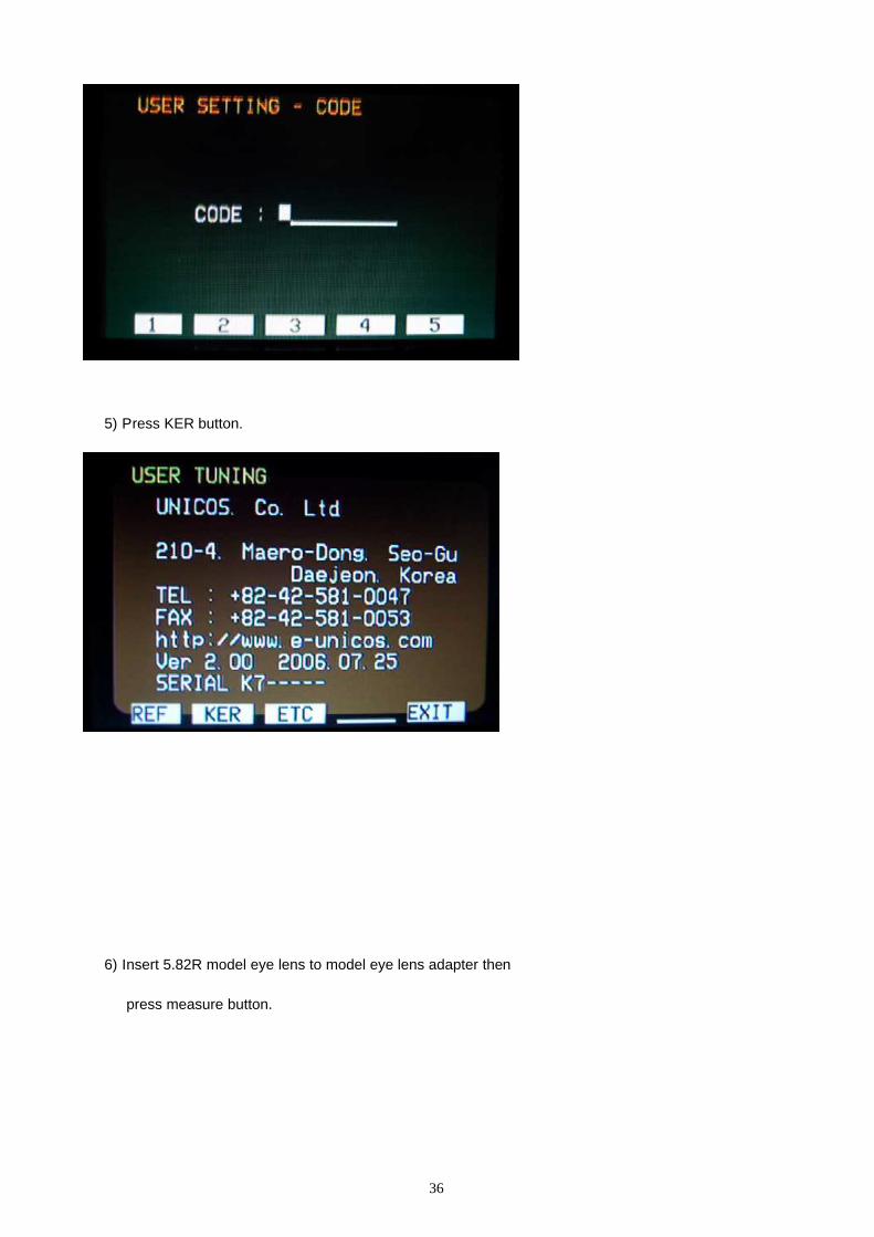
4) Press 2154225342.
28
5) Press REF button.
6) Insert 0D spherical model eye lens to model eye lens adapter then
press measure button.
29
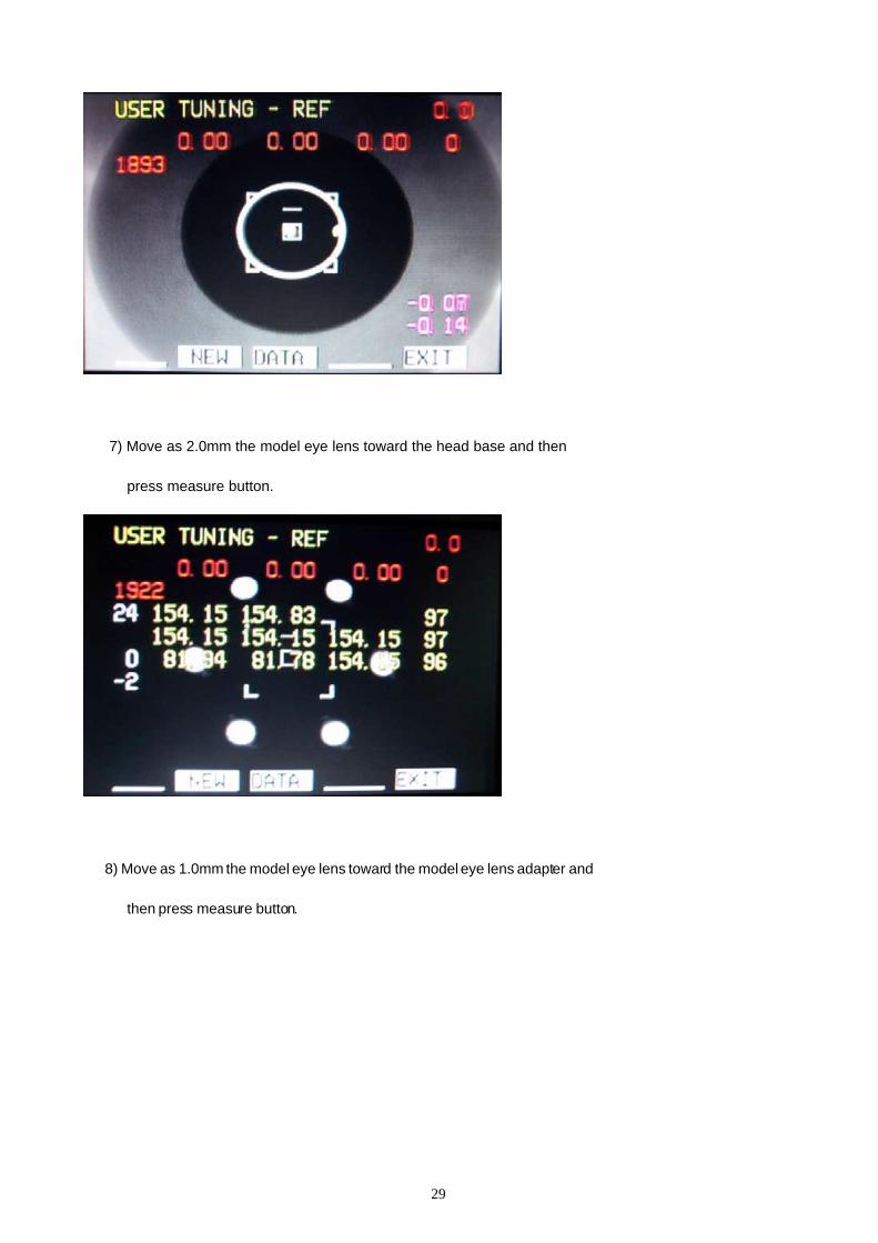
7) Move as 2.0mm the model eye lens toward the head base and then
press measure button.
8) Move as 1.0mm the model eye lens toward the model eye lens adapter and
then press measure button.
30
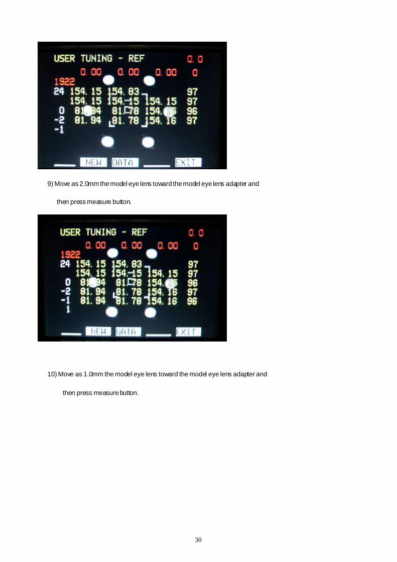
9) Move as 2.0mm themodel eye lens toward themodel eye lens adapter and
then press measure button.
10) Move as 1.0mm the model eye lens toward the model eye lens adapter and
then press measurebutton.
31
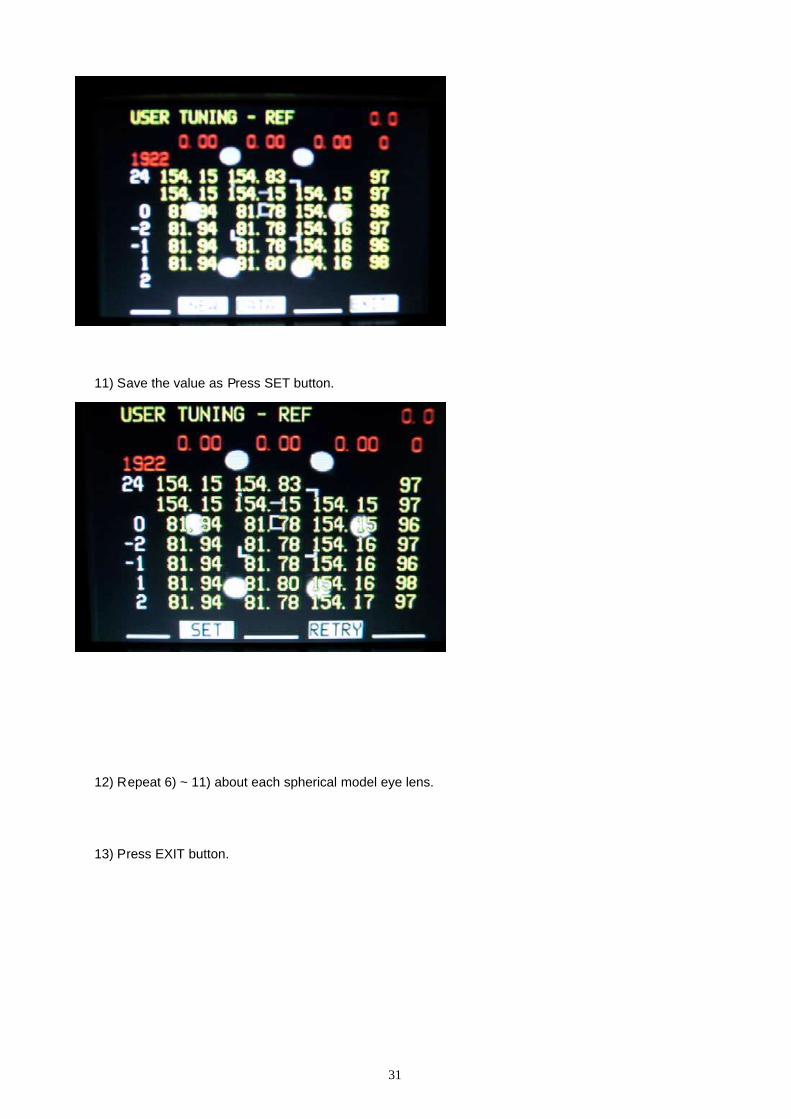
11) Save the value as Press SET button.
12) Repeat 6) ~ 11) about each spherical model eye lens.
13) Press EXIT button.
32
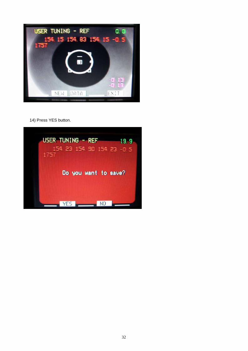
14) Press YES button.

33
34
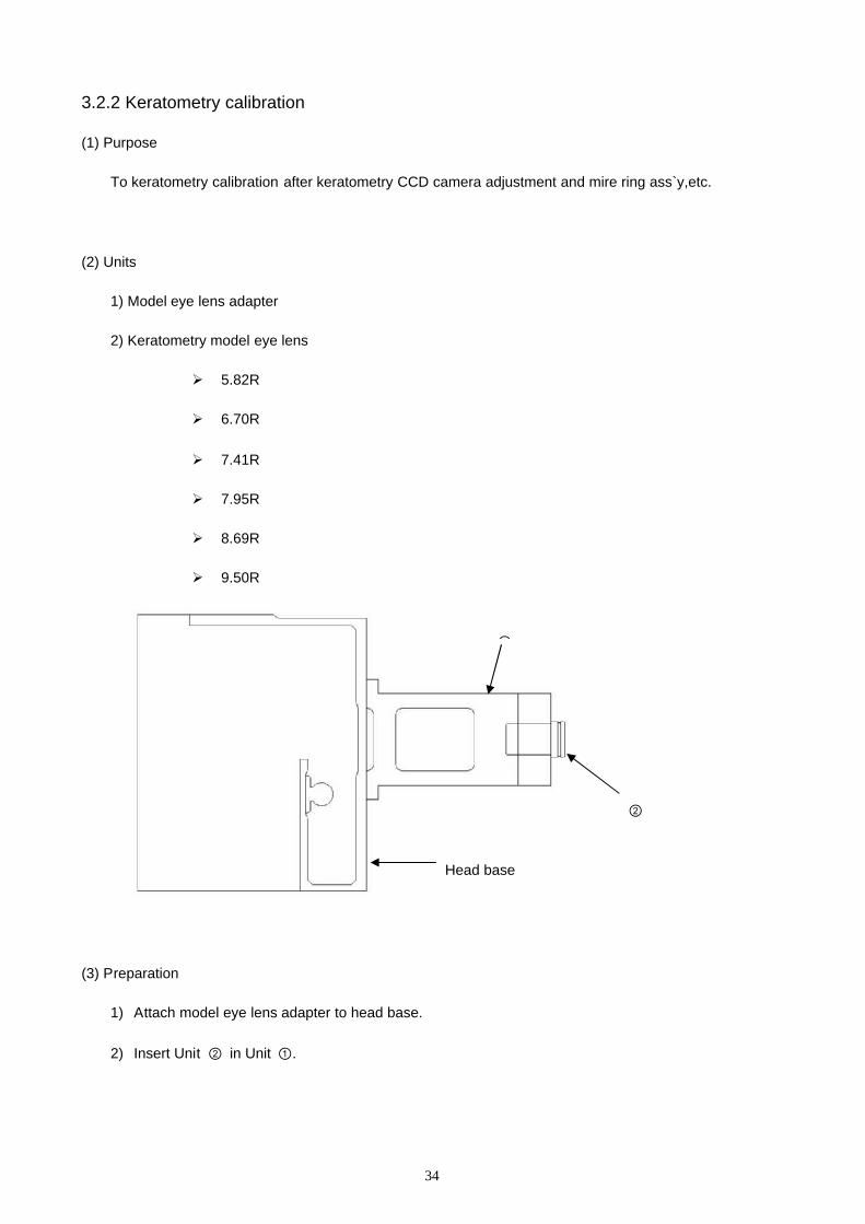
3.2.2 Keratometry calibration
(1) Purpose
To keratometry calibration after keratometry CCD camera adjustment and mire ring ass`y,etc.
(2) Units
1) Model eye lens adapter
2) Keratometry model eye lens
5.82R
6.70R
7.41R
7.95R
8.69R
9.50R
(3) Preparation
1) Attach model eye lens adapter to head base.
2) Insert Unit ② in Unit ①.
Head base
①
②
35
(4) Calibration
1) Press the MENU button.
2) Press the ↑,↓button.
3) Select CODE and then press EDIT button.
4) Press 2154225342.
36
5) Press KER button.
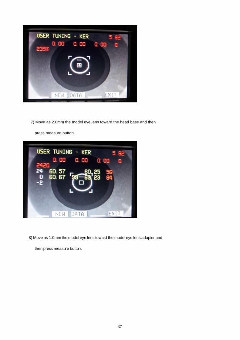
6) Insert 5.82R model eye lens to model eye lens adapter then
press measure button.
37
7) Move as 2.0mm the model eye lens toward the head base and then
press measure button.
8) Move as 1.0mm the model eye lens toward the model eye lens adapter and
then press measure button.

38
9) Move as 2.0mm the model eye lens toward the model eye lens adapter and
then press measure button.
10) Move as 1.0mm the model eye lens toward the model eye lens adapter and
then press measure button.
39
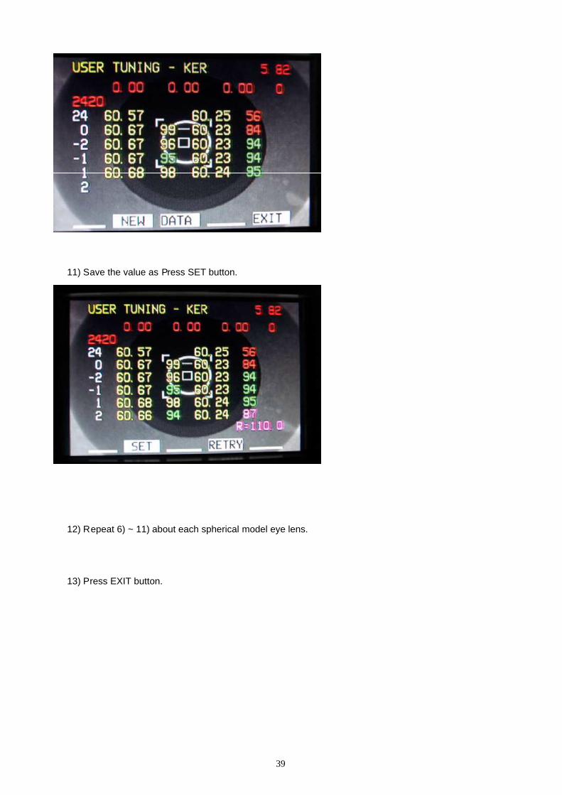
11) Save the value as Press SET button.
12) Repeat 6) ~ 11) about each spherical model eye lens.
13) Press EXIT button.
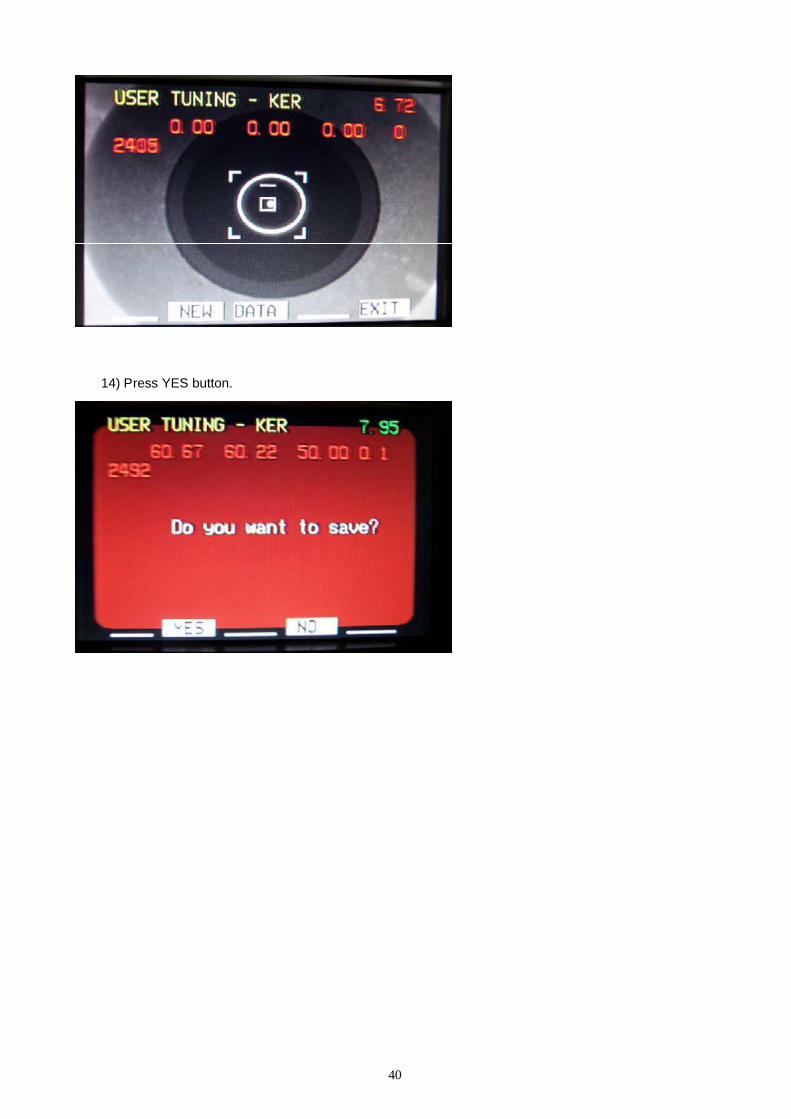
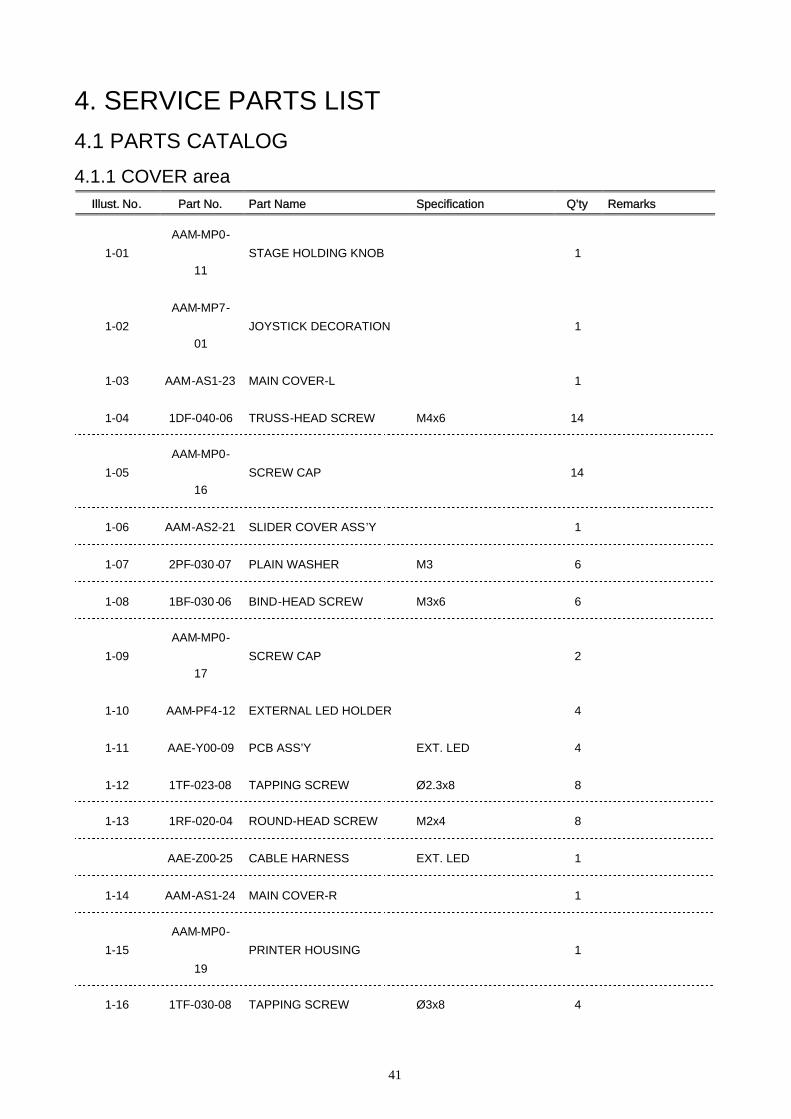
40
14) Press YES button.
41
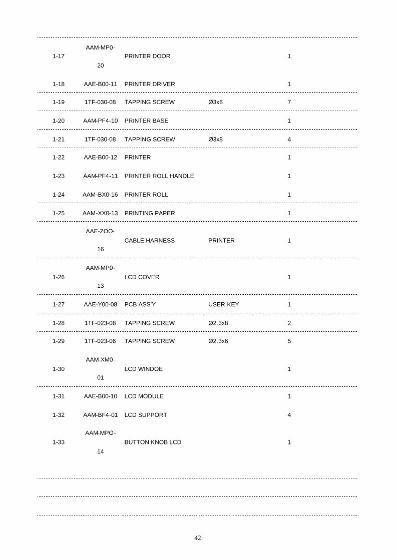
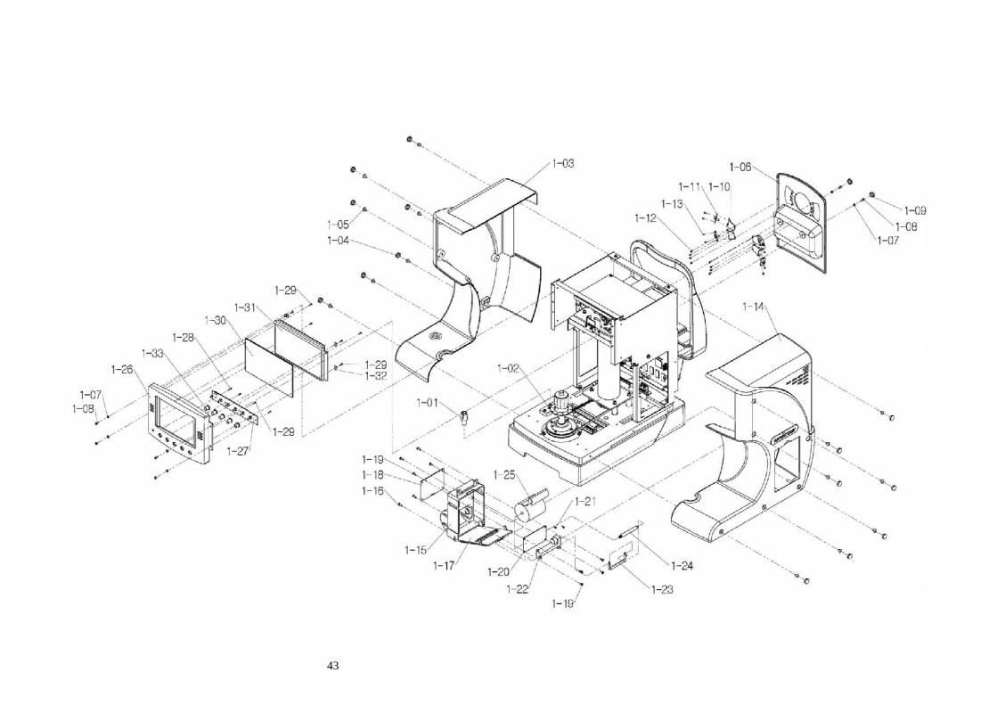
4. SERVICE PARTS LIST4.1 PARTS CATALOG
4.1.1 COVER areaIllust. No. Part No. Part Name Specification Q’ty Remarks
1-01AAM-MP0-
11STAGE HOLDING KNOB 1
1-02AAM-MP7-
01JOYSTICK DECORATION 1
1-03 AAM-AS1-23 MAIN COVER-L 1
1-04 1DF-040-06 TRUSS-HEAD SCREW M4x6 14
1-05AAM-MP0-
16SCREW CAP 14
1-06 AAM-AS2-21 SLIDER COVER ASS’Y 1
1-07 2PF-030-07 PLAIN WASHER M3 6
1-08 1BF-030-06 BIND-HEAD SCREW M3x6 6
1-09AAM-MP0-
17SCREW CAP 2
1-10 AAM-PF4-12 EXTERNAL LED HOLDER 4
1-11 AAE-Y00-09 PCB ASS’Y EXT. LED 4
1-12 1TF-023-08 TAPPING SCREW Ø2.3x8 8
1-13 1RF-020-04 ROUND-HEAD SCREW M2x4 8
AAE-Z00-25 CABLE HARNESS EXT. LED 1
1-14 AAM-AS1-24 MAIN COVER-R 1
1-15AAM-MP0-
19PRINTER HOUSING 1
1-16 1TF-030-08 TAPPING SCREW Ø3x8 4
42
1-17AAM-MP0-
20PRINTER DOOR 1
1-18 AAE-B00-11 PRINTER DRIVER 1
1-19 1TF-030-08 TAPPING SCREW Ø3x8 7
1-20 AAM-PF4-10 PRINTER BASE 1
1-21 1TF-030-08 TAPPING SCREW Ø3x8 4
1-22 AAE-B00-12 PRINTER 1
1-23 AAM-PF4-11 PRINTER ROLL HANDLE 1
1-24 AAM-BX0-16 PRINTER ROLL 1
1-25 AAM-XX0-13 PRINTING PAPER 1
AAE-ZOO-
16CABLE HARNESS PRINTER 1
1-26AAM-MP0-
13LCD COVER 1
1-27 AAE-Y00-08 PCB ASS’Y USER KEY 1
1-28 1TF-023-08 TAPPING SCREW Ø2.3x8 2
1-29 1TF-023-06 TAPPING SCREW Ø2.3x6 5
1-30AAM-XM0-
01LCD WINDOE 1
1-31 AAE-B00-10 LCD MODULE 1
1-32 AAM-BF4-01 LCD SUPPORT 4
1-33AAM-MPO-
14BUTTON KNOB LCD 1
43

44
45
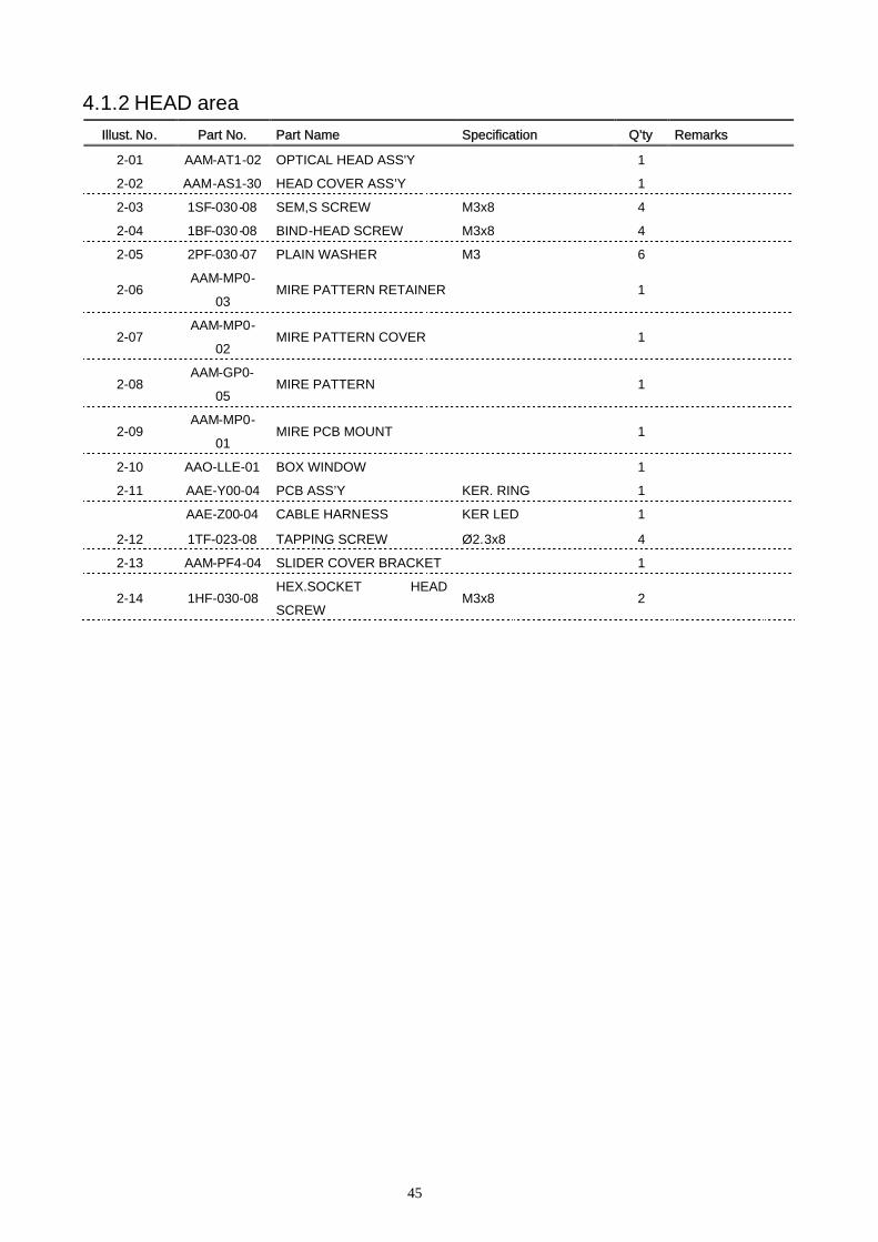
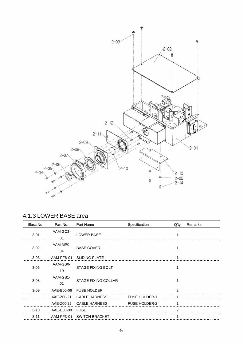
4.1.2 HEAD areaIllust. No. Part No. Part Name Specification Q’ty Remarks
2-01 AAM-AT1-02 OPTICAL HEAD ASS'Y 1
2-02 AAM-AS1-30 HEAD COVER ASS’Y 1
2-03 1SF-030-08 SEM,S SCREW M3x8 4
2-04 1BF-030-08 BIND-HEAD SCREW M3x8 4
2-05 2PF-030-07 PLAIN WASHER M3 6
2-06AAM-MP0-
03MIRE PATTERN RETAINER 1
2-07AAM-MP0-
02MIRE PATTERN COVER 1
2-08AAM-GP0-
05MIRE PATTERN 1
2-09AAM-MP0-
01MIRE PCB MOUNT 1
2-10 AAO-LLE-01 BOX WINDOW 1
2-11 AAE-Y00-04 PCB ASS’Y KER. RING 1
AAE-Z00-04 CABLE HARNESS KER LED 1
2-12 1TF-023-08 TAPPING SCREW Ø2.3x8 4
2-13 AAM-PF4-04 SLIDER COVER BRACKET 1
2-14 1HF-030-08HEX.SOCKET HEAD
SCREWM3x8 2
46
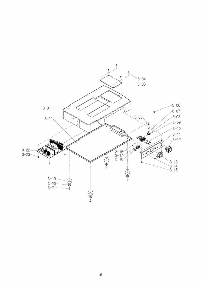
4.1.3 LOWER BASE areaIllust. No. Part No. Part Name Specification Q’ty Remarks
3-01AAM-GC3-
01LOWER BASE 1
3-02AAM-MP0-
04BASE COVER 1
3-03 AAM-PF8-01 SLIDING PLATE 1
3-05AAM-GS0-
10STAGE FIXING BOLT 1
3-08AAM-GB1-
01STAGE FIXING COLLAR 1
3-09 AAE-B00-06 FUSE HOLDER 2
AAE-Z00-21 CABLE HARNESS FUSE HOLDER-1 1
AAE-Z00-22 CABLE HARNESS FUSE HOLDER-2 1
3-10 AAE-B00-08 FUSE 2
3-11 AAM-PF3-01 SWITCH BRACKET 1

47
3-12 AAE-B00-04 POWER SWITCH 1
AAE-Z00-23 CABLE HARNESS SWITCH-1 1
AAE-Z00-24 CABLE HARNESS SWITCH-2 1
3-13 AAE-B00-05 AC INLET 1
AAE-Z00-18 CABLE HARNESS AC IN-1 1
AAE-Z00-19 CABLE HARNESS AC IN-2 1
AAE-Z00-20 CABLE HARNESS SMPS-FG 1
3-16 AAE-B00-07 RCA JACK 1
AAE-Z00-15 CABLE HARNESS EXT. MONITOR 1
3-17 AAE-Z00-17 CABLE HARNESS RS232 1
3-19 AAM-BR0-01 FOOT 4
3-20 2PF-040-16 PLAIN WASHER 4
3-22 AAE-B00-03 SMPS 1
48
49
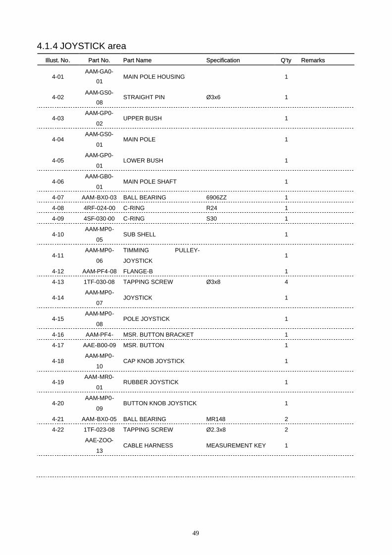
4.1.4 JOYSTICK areaIllust. No. Part No. Part Name Specification Q’ty Remarks
4-01AAM-GA0-
01MAIN POLE HOUSING 1
4-02AAM-GS0-
08STRAIGHT PIN Ø3x6 1
4-03AAM-GP0-
02UPPER BUSH 1
4-04AAM-GS0-
01MAIN POLE 1
4-05AAM-GP0-
01LOWER BUSH 1
4-06AAM-GB0-
01MAIN POLE SHAFT 1
4-07 AAM-BX0-03 BALL BEARING 6906ZZ 1
4-08 4RF-024-00 C-RING R24 1
4-09 4SF-030-00 C-RING S30 1
4-10AAM-MP0-
05SUB SHELL 1
4-11AAM-MP0-
06
TIMMING PULLEY-
JOYSTICK1
4-12 AAM-PF4-08 FLANGE-B 1
4-13 1TF-030-08 TAPPING SCREW Ø3x8 4
4-14AAM-MP0-
07JOYSTICK 1
4-15AAM-MP0-
08POLE JOYSTICK 1
4-16 AAM-PF4- MSR. BUTTON BRACKET 1
4-17 AAE-B00-09 MSR. BUTTON 1
4-18AAM-MP0-
10CAP KNOB JOYSTICK 1
4-19AAM-MR0-
01RUBBER JOYSTICK 1
4-20AAM-MP0-
09BUTTON KNOB JOYSTICK 1
4-21 AAM-BX0-05 BALL BEARING MR148 2
4-22 1TF-023-08 TAPPING SCREW Ø2.3x8 2
AAE-ZOO-
13CABLE HARNESS MEASUREMENT KEY 1

50
51
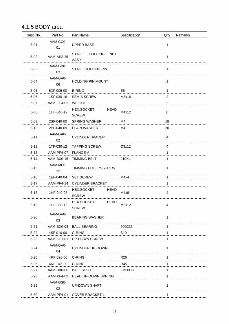
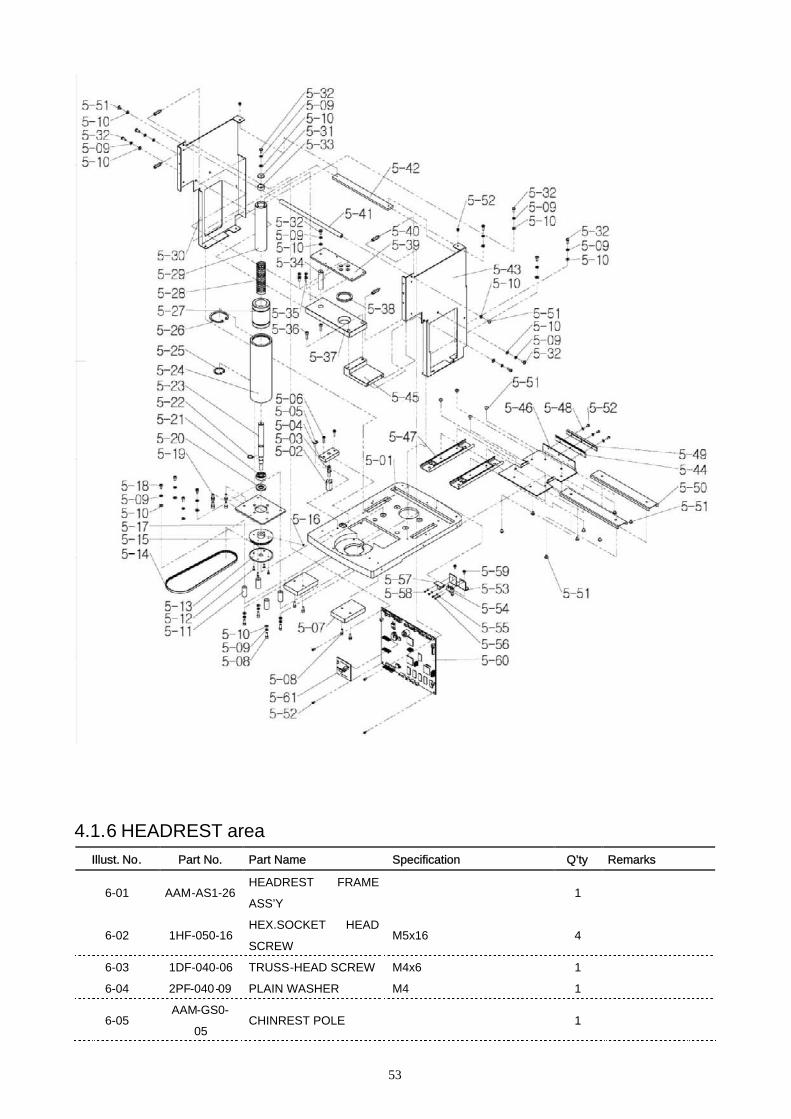
4.1.5 BODY areaIllust. No. Part No. Part Name Specification Q’ty Remarks
5-01AAM-GC0-
01UPPER BASE 1
5-02 AAM-AS2-25STAGE HOLDING NUT
AAS’Y1
5-03AAM-GB0-
03STAGE HOLDING PIN 1
5-04AAM-GA0-
06HOLDING PIN MOUNT 1
5-05 5XF-006-00 E-RING E6 1
5-06 1SF-030-16 SEM’S SCREW M3x16 2
5-07 AAM-GF4-02 WEIGHT 2
5-08 1HF-040-12HEX.SOCKET HEAD
SCREWM4x12 8
5-09 2SF-040-00 SPRING WASHER M4 18
5-10 2PF-040-09 PLAIN WASHER M4 20
5-11AAM-GA0-
02CYLINDER SPACER 4
5-12 1TF-030-12 TAPPING SCREW Ø3x12 4
5-13 AAM-PF4-07 FLANGE-A 1
5-14 AAM-BX0-15 TIMMING BELT 210XL 1
5-15AAM-MP0-
12TIMMING PULLEY-SCREW 1
5-16 1EF-040-04 SET SCREW M4x4 1
5-17 AAM-PF4-14 CYLINDER BRACKET 1
5-18 1HF-040-08HEX.SOCKET HEAD
SCREWM4x8 4
5-19 1HF-050-12HEX.SOCKET HEAD
SCREWM5x12 4
5-20AAM-GA0-
03BEARING WASHER 1
5-21 AAM-BX0-03 BALL BEARING 6000ZZ 1
5-22 4SF-010-00 C-RING S10 1
5-23 AAM-GF7-01 UP-DOWN SCREW 1
5-24AAM-GA0-
04CYLINDER UP-DOWN 1
5-26 4RF-026-00 C-RING R26 1
5-26 4RF-045-00 C-RING R45 1
5-27 AAM-BX0-06 BALL BUSH LM30UU 1
5-28 AAM-XF4-02 HEAD UP-DOWN SPRING 1
5-29AAM-GS0-
02UP-DOWN SHAFT 1
5-30 AAM-PF4-01 COVER BRACKET-L 1
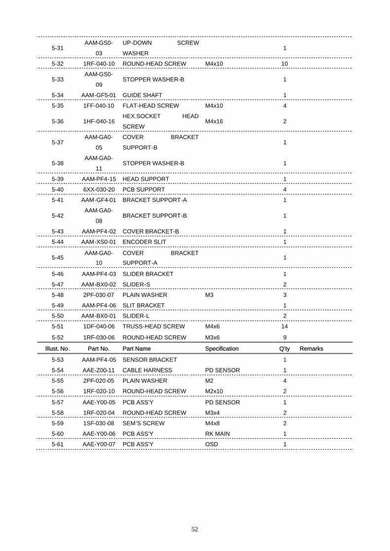
52
5-31AAM-GS0-
03
UP-DOWN SCREW
WASHER1
5-32 1RF-040-10 ROUND-HEAD SCREW M4x10 10
5-33AAM-GS0-
09STOPPER WASHER-B 1
5-34 AAM-GF5-01 GUIDE SHAFT 1
5-35 1FF-040-10 FLAT-HEAD SCREW M4x10 4
5-36 1HF-040-16HEX.SOCKET HEAD
SCREWM4x16 2
5-37AAM-GA0-
05
COVER BRACKET
SUPPORT-B1
5-38AAM-GA0-
11STOPPER WASHER-B 1
5-39 AAM-PF4-15 HEAD SUPPORT 1
5-40 6XX-030-20 PCB SUPPORT 4
5-41 AAM-GF4-01 BRACKET SUPPORT-A 1
5-42AAM-GA0-
08BRACKET SUPPORT-B 1
5-43 AAM-PF4-02 COVER BRACKET-B 1
5-44 AAM-XS0-01 ENCODER SLIT 1
5-45AAM-GA0-
10
COVER BRACKET
SUPPORT-A1
5-46 AAM-PF4-03 SLIDER BRACKET 1
5-47 AAM-BX0-02 SLIDER-S 2
5-48 2PF-030-07 PLAIN WASHER M3 3
5-49 AAM-PF4-06 SLIT BRACKET 1
5-50 AAM-BX0-01 SLIDER-L 2
5-51 1DF-040-06 TRUSS-HEAD SCREW M4x6 14
5-52 1RF-030-06 ROUND-HEAD SCREW M3x6 9
Illust. No. Part No. Part Name Specification Q’ty Remarks
5-53 AAM-PF4-05 SENSOR BRACKET 1
5-54 AAE-Z00-11 CABLE HARNESS PD SENSOR 1
5-55 2PF-020-05 PLAIN WASHER M2 4
5-56 1RF-020-10 ROUND-HEAD SCREW M2x10 2
5-57 AAE-Y00-05 PCB ASS’Y PD SENSOR 1
5-58 1RF-020-04 ROUND-HEAD SCREW M3x4 2
5-59 1SF-030-08 SEM’S SCREW M4x8 2
5-60 AAE-Y00-06 PCB ASS’Y RK MAIN 1
5-61 AAE-Y00-07 PCB ASS’Y OSD 1
53
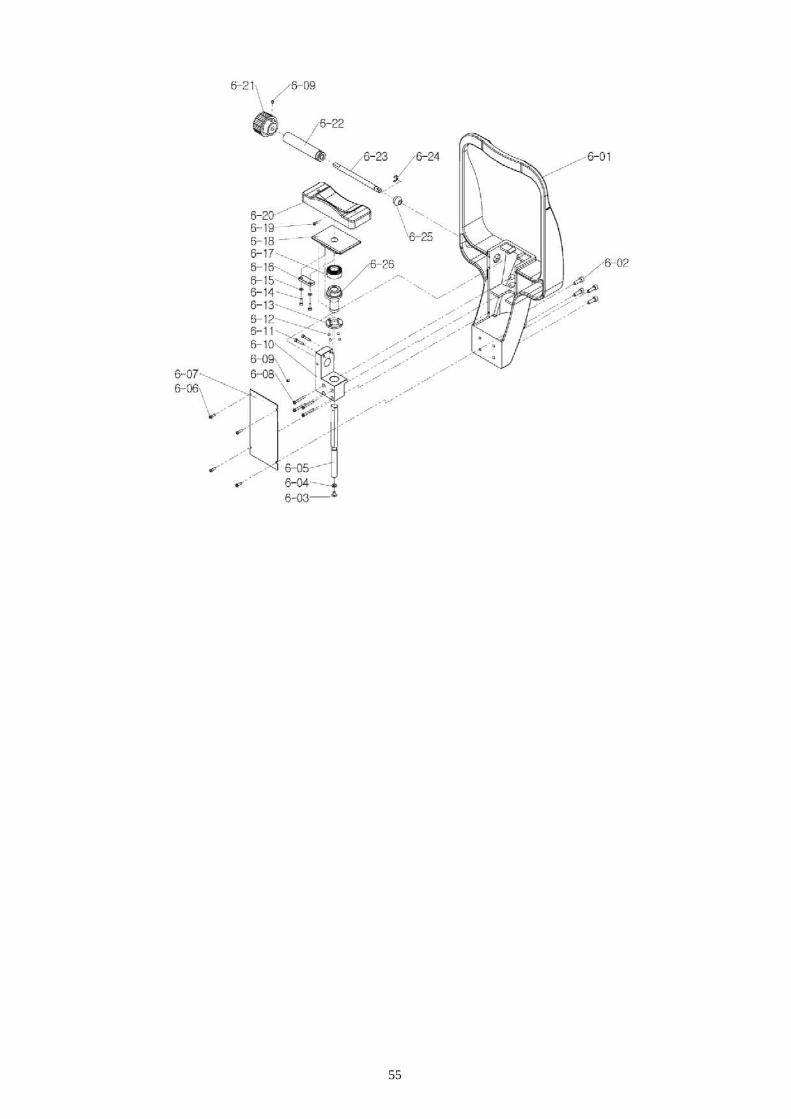
4.1.6 HEADREST areaIllust. No. Part No. Part Name Specification Q’ty Remarks
6-01 AAM-AS1-26HEADREST FRAME
ASS’Y1
6-02 1HF-050-16HEX.SOCKET HEAD
SCREWM5x16 4
6-03 1DF-040-06 TRUSS-HEAD SCREW M4x6 1
6-04 2PF-040-09 PLAIN WASHER M4 1
6-05AAM-GS0-
05CHINREST POLE 1
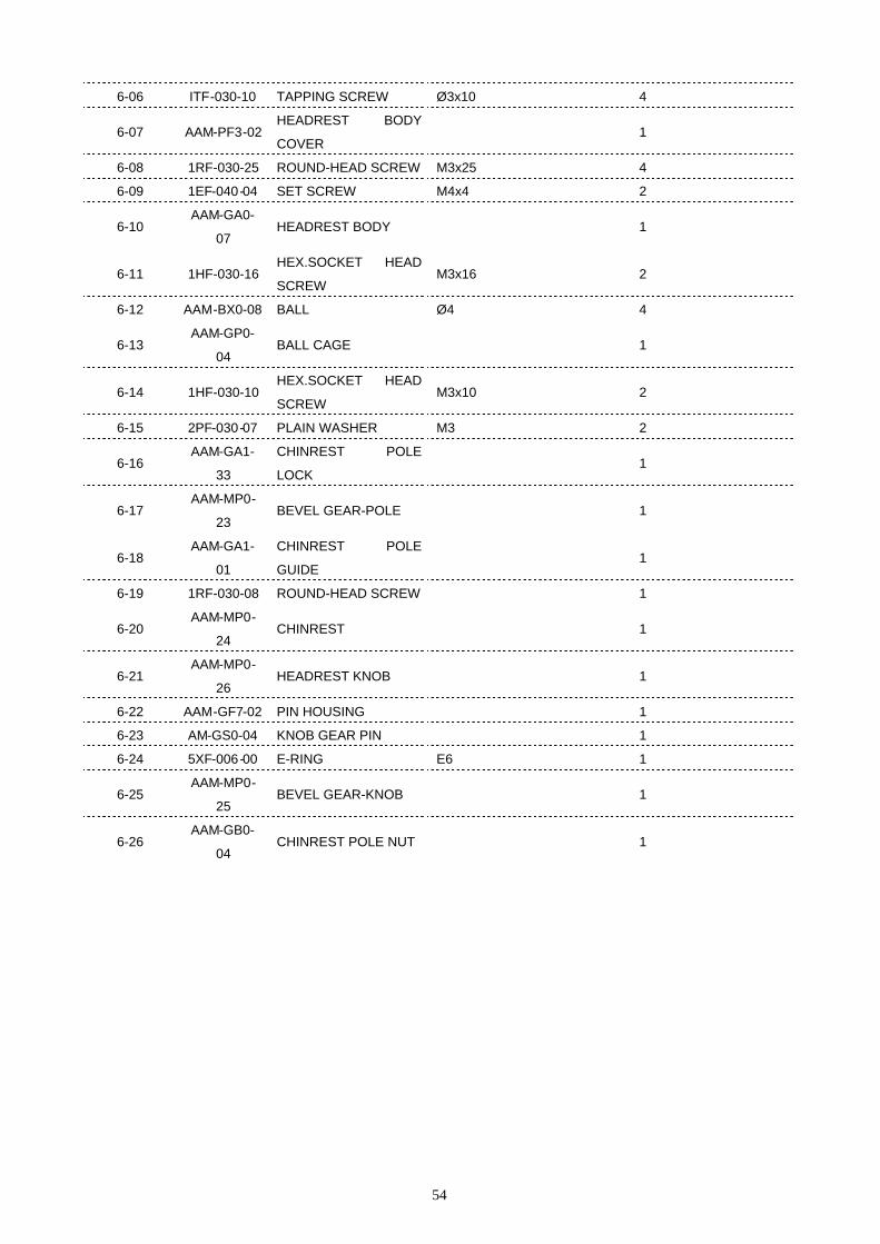
54
6-06 ITF-030-10 TAPPING SCREW Ø3x10 4
6-07 AAM-PF3-02HEADREST BODY
COVER1
6-08 1RF-030-25 ROUND-HEAD SCREW M3x25 4
6-09 1EF-040-04 SET SCREW M4x4 2
6-10AAM-GA0-
07HEADREST BODY 1
6-11 1HF-030-16HEX.SOCKET HEAD
SCREWM3x16 2
6-12 AAM-BX0-08 BALL Ø4 4
6-13AAM-GP0-
04BALL CAGE 1
6-14 1HF-030-10HEX.SOCKET HEAD
SCREWM3x10 2
6-15 2PF-030-07 PLAIN WASHER M3 2
6-16AAM-GA1-
33
CHINREST POLE
LOCK1
6-17AAM-MP0-
23BEVEL GEAR-POLE 1
6-18AAM-GA1-
01
CHINREST POLE
GUIDE1
6-19 1RF-030-08 ROUND-HEAD SCREW 1
6-20AAM-MP0-
24CHINREST 1
6-21AAM-MP0-
26HEADREST KNOB 1
6-22 AAM-GF7-02 PIN HOUSING 1
6-23 AM-GS0-04 KNOB GEAR PIN 1
6-24 5XF-006-00 E-RING E6 1
6-25AAM-MP0-
25BEVEL GEAR-KNOB 1
6-26AAM-GB0-
04CHINREST POLE NUT 1
55

56
4.2 SERVICE PARTS LIST
4.1.1 OPTICAL HEAD ASSEMBLY (AAM-AT1-01)Part No. Part Name Specification Q’ty Illust. No. Remarks
AAM-AT1-02 OPTICAL HEAD ASS'Y 1 2-01 RETURN only
AAM-AS1-30 HEAD COVER ASS’Y 1 2-02
AAM-MP0-
03MIRE PATTERN RETAINER 1 2-06
AAM-MP0-
02MIRE PATTERN COVER 1 2-07
AAM-GP0-05 MIRE PATTERN 1 2-08
AAM-MP0-
01MIRE PCB MOUNT 1 2-09
AAO-LLE-01 BOX WINDOW 1 2-10
AAE-Y00-04 PCB ASS’Y KER. RING 1 2-11
AAE-Z00-04 CABLE HARNESS KER LED 1
AAM-PF4-04 SLIDER COVER BRACKET 1 2-13
4.2 LOWER BASE ASS’Y (AAM-AT1-03)Part No. Part Name Specification Q’ty Illust. No. Remarks
AAM-GC3-
01LOWER BASE
1 3-01 RETURN only
AAE-B00-03 SMPS 1 3-22 RETURN only
AAE-Z00-14 CABLE HARNESS POWER 1
AAM-AS2-12 SWITCH ASS'Y 1 NOTE 1
AAM-PF8-01 SLIDING PLATE 1 3-03
AAM-MP0-
04BASE COVER
1 3-02
AAM-GS0-10 STAGE FIXING BOLT 1 3-05
5XF-006-00 E-RING 1 3-06
AAM-GB1-01 STAGE FIXING COLLAR 1 3-08
AAM-BR0-01 FOOT 1 3-19
AAM-AS2-14 STAGY MOVING ASS'Y 1 5-46,5-47,5-50
AAM-XS0-01 ENCODER SLIT 1 5-44
AAM-PF4-06 SLIT BRACKET 1 5-49
AAM-XP0-06 MAIN SWITCH STICKER 1
AAM-XP0-07 WARNING STICKER 1
NOTE 1: 3-09,3-10,3-11,3-12,3-13,3-14,3-16,3-17,3-18
4.3 JOYSTICK ASS’Y (AAM-AT1-04)Part No. Part Name Specification Q’ty Illust. No. Remarks
AAM-AT1-05 JOYSTICK ASS'Y 1 NOTE 1 RETURN only

57
AAM-MP0-
09BUTTON KNOB JOYSTICK
1 4-20
AAM-MR0-
01RUBBER JOYSTICK
1 4-19
AAM-MP0-
10CAP KNOB JOYSTICK
1 4-18
NOTE 1: 4-01,4-02,4-03,4-04,4-05,4-06,4-07,4-08,4-09,4-10,4-11,4-12,4-13,4-14,4-15,4-16,4-17,4-21,4-22,4-23
4.4 UPPER BASE ASS’Y (AAM-AT1-06)Part No. Part Name Specification Q’ty Illust. No. Remarks
AAM-GC0-
01UPPER BASE 1
5-01 RETURN only
AAM-AS2-17STAGE HOLDING KNOB
ASS'Y1
5-02,5-03,5-04,5-05
AAM-MP0-
11STAGE HOLDING KNOB 1
1-01
AAM-GA0-02 CYLINDER SAPCER 4 5-11
AAM-GF4-02 WEIGHT 2 5-07
AAM-PF4-05 SENSOR BRACKET 1 5-53
AAE-Y00-05 PCB ASS'Y PD SENSOR 1 5-57
AAE-Z00-11 CABLE HARNESS PD SENSOR 1 5-54
AAM-AS1-20 CYLINDER ASS'Y 1 NOTE 1 RETURN only
AAM-AS2-19 TIMMING PULLEY ASS'Y 1 5-12,5-13,5-15,5-16
AAM-GA0-05COVER BRACKET
SUPPORT-B1
5-37
AAM-GA0-10COVER BRACKET
SUPPORT-A1
5-45
AAM-PF4-01 COVER BRACKET-L 1 5-30
AAM-PF4-02 COVER BRACKET-R 1 5-43
AAM-GF4-01 BRACKET SUPPORT "A" 1 5-41
AAM-GA0-08 BRACKET SUPPORT "B" 1 5-42
AAM-PF4-15 HEAD SUPPORT 1 5-39
AAM-GF5-01 GUIDE SHAFT 1 5-34
AAM-GA0-11 STOPPER WASHER B 1 5-38
6XX-030-20 PCB SUPPORT 4 5-40
AAE-Y00-06 PCB ASS'Y RK MAIN 1 5-60 RETURN only
AAE-Y00-07 PCB ASS'Y OSD 1 5-61 RETURN only
NOTE 1: 5-09,5-10,5-17,5-18,5-20,5-21,5-22,5-23,5-24,5-25,5-26,5-27,5-28,5-29,5-31,5-32,5-33
4.5 COVER ASS’Y (AAM-AT1-07)Part No. Part Name Specification Q’ty Illust. No. Remarks
AAM-MP0-
13LCD COVER 1
58
AAM-XM0-
01LCD WINDOW 1
AAE-B00-10 LCD MODULE 1 RETURN only
AAM-BF4-01 LCD SUPPORT 4
AAM-MP0-
14BUTTON KNOB LCD 1
AAE-Y00-08 PCB ASS'Y USER KEY 1
AAE-Z00-12 CABLE HARNESSFUNCTION
KEY1
AAM-AS1-23 MAIN COVER-L ASS'Y 1 1-03
AAM-MP0-
16SCREW CAP 14
1-04
AAM-AS1-24 MAIN COVER-R ASS'Y 1 1-14
AAM-MP0-
19PRINTER HOUSING 1
1-15
AAE-B00-11 PRINTER DRIVER 1 1-18 RETURN only
AAM-PF4-10 PRINTER BASE 1 1-20
AAE-B00-12 PRINTER 1 1-22 RETURN only
AAE-Z00-16 CABLE HARNESS PRINTER 1
AAM-PF4-11 PRINTER ROLL HANDLE 1 1-23
AAM-MP0-
20PRINTER DOOR 1
1-17
AAM-AS2-21 SLIDER COVER ASS'Y 1 1-06
AAM-PF4-12 EXTERNAL LED HOLDER 4 1-10
AAE-Y00-09 PCB ASS'Y EXT. LED 4 1-11
AAE-Z00-25 CABLE HARNESS EXT. LED 1
AAM-MP0-
17SCREW CAP 2
1-09
AAM-MP7-
01JOYSTICK DECORATION 1
1-02
AAM-MP0-
13LCD COVER 1
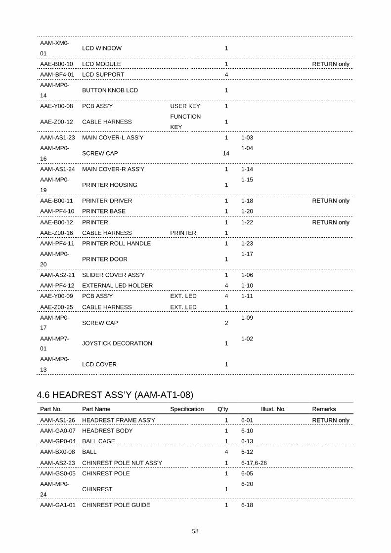
4.6 HEADREST ASS’Y (AAM-AT1-08)Part No. Part Name Specification Q’ty Illust. No. Remarks
AAM-AS1-26 HEADREST FRAME ASS'Y 1 6-01 RETURN only
AAM-GA0-07 HEADREST BODY 1 6-10
AAM-GP0-04 BALL CAGE 1 6-13
AAM-BX0-08 BALL 4 6-12
AAM-AS2-23 CHINREST POLE NUT ASS'Y 1 6-17,6-26
AAM-GS0-05 CHINREST POLE 1 6-05
AAM-MP0-
24CHINREST 1
6-20
AAM-GA1-01 CHINREST POLE GUIDE 1 6-18
59
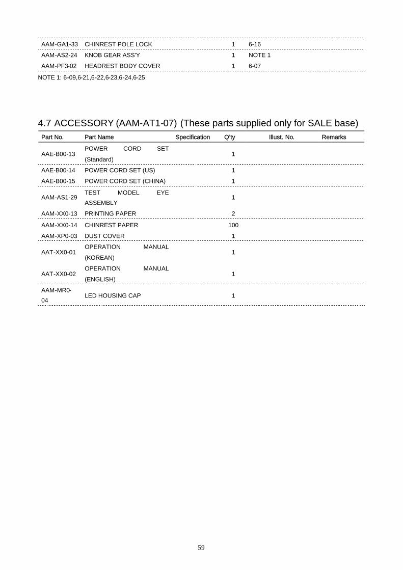
AAM-GA1-33 CHINREST POLE LOCK 1 6-16
AAM-AS2-24 KNOB GEAR ASS'Y 1 NOTE 1
AAM-PF3-02 HEADREST BODY COVER 1 6-07
NOTE 1: 6-09,6-21,6-22,6-23,6-24,6-25
4.7 ACCESSORY (AAM-AT1-07) (These parts supplied only for SALE base)Part No. Part Name Specification Q’ty Illust. No. Remarks
AAE-B00-13POWER CORD SET
(Standard)1
AAE-B00-14 POWER CORD SET (US) 1
AAE-B00-15 POWER CORD SET (CHINA) 1
AAM-AS1-29TEST MODEL EYE
ASSEMBLY1
AAM-XX0-13 PRINTING PAPER 2
AAM-XX0-14 CHINREST PAPER 100
AAM-XP0-03 DUST COVER 1
AAT-XX0-01OPERATION MANUAL
(KOREAN)1
AAT-XX0-02OPERATION MANUAL
(ENGLISH)1
AAM-MR0-
04LED HOUSING CAP 1