
Universite Paris—Sud - KTH · PDF file52 PROTOTYPING TOOLS AND TECHNIQUES Michel...
26
52 PROTOTYPING TOOLS AND TECHNIQUES Michel Beaudouin-Lafon Universite Paris—Sud Wendy Mackay Institut National de Recherche en Informatique et en Automatique (INRIA) Introduction 1007 What Is a Prototype? 1007 Prototypes As Design Artifacts 1007 Representation 1007 Precision 1008 Interactivity 1008 Evolution 1009 Prototypes and the Design Process 1009 User-Centered Design 1009 Participatory Design 1010 Exploring the Design Space 1010 Expanding the Design Space: Generating Ideas 1011 Contracting the Design Space: Selecting Alternatives ... 101 2 in in Michel Beaudouin-Lafon and Wendy Mackay (2003). Prototyping Rapid Prototypes 1014 Offline Rapid Prototyping Techniques 1014 Online Rapid Prototyping Techniques 1017 Iterative Prototypes 1021 Software Tools 1022 Software Environments 1025 Evolutionary Prototypes 1026 Software Architectures 1026 iin Design Patterns 1028 Summary 1029 References 1029 1006
Transcript of Universite Paris—Sud - KTH · PDF file52 PROTOTYPING TOOLS AND TECHNIQUES Michel...
52
PROTOTYPING TOOLS AND TECHNIQUES
Michel Beaudouin-LafonUniversite Paris—Sud
Wendy MackayInstitut National de Recherche en
Informatique et en Automatique (INRIA)
Introduction 1007What Is a Prototype? 1007
Prototypes As Design Artifacts 1007Representation 1007Precision 1008Interactivity 1008Evolution 1009
Prototypes and the Design Process 1009User-Centered Design 1009Participatory Design 1010Exploring the Design Space 1010Expanding the Design Space: Generating Ideas 1011Contracting the Design Space: Selecting Alternatives ... 101
2 in in
Michel Beaudouin-Lafon and Wendy Mackay (2003). Prototyping Tools And Techniques In: J. A. Jacko and A. Sears (Eds) The Human-Computer Interaction Handbook. © 2003 by Lawrence Erlbaum Associates. Prototyping Strategies 1013Rapid Prototypes 1014
Offline Rapid Prototyping Techniques 1014Online Rapid Prototyping Techniques 1017
Iterative Prototypes 1021Software Tools 1022Software Environments 1025
Evolutionary Prototypes 1026Software Architectures 1026iin
Design Patterns 1028
Summary 1029References 1029
1006
52. Prototyping Tools and Techniques • 1007
INTRODUCTION
"A good design is better than you think."—RexHeftman, cited by Raskin, 2000, p. 143.
Design is about making choices. In many fields that require cre-ativity and engineering skill, such as architecture or automobiledesign, prototypes both inform the design process and help de-signers select the best solution. This chapter describes tools andtechniques for using prototypes to design interactive systems.The goal is to illustrate how they can help designers generateand share new ideas, get feedback from users or customers,choose among design alternatives, and articulate reasons fortheir final choices.
We begin with our definition of a prototype and then discussprototypes as design artifacts, introducing four dimensions foranalyzing them. We then discuss the role of prototyping withinthe design process, in particular, the concept of a design spaceand how it is expanded and contracted by generating and select-ing design ideas. The next three sections describe specific pro-totyping approaches: rapid prototyping, both offline and online,for early stages of design; iterative prototyping, which uses on-line development tools; and evolutionary prototyping, whichmust be based on a sound software architecture.
What Is a Prototype?
We define a prototype as a concrete representation of part or allof an interactive system. A prototype is a tangible artifact, notan abstract description that requires interpretation. Designers,as well as managers, developers, customers, and end users, canuse these artifacts to envision and reflect on the final system.
Prototypes may be denned differently in other fields. For ex-ample, an architectural prototype is a scaled-down model ofthe final building. This is not possible for interactive systemprototypes: The designer may limit the amount of informationthe prototype can handle, but the actual interface must be pre-sented at full scale. Thus, a prototype interface to a databasemay handle only a small pseudo-database but must still presenta full-size display and interaction techniques. Full-scale, one-of-a-kind models, such as a handmade dress sample, are another typeof prototype. These usually require an additional design phaseto mass produce the final design. Some interactive system pro-totypes begin as one-of-a-kind models that are then distributedwidely (because the cost of duplicating software is so low);however, most successful software prototypes evolve into thefinal product and then continue to evolve as new versions ofthe software are released.
Hardware and software engineers often create prototypesto study the feasibility of a technical process. They conductsystematic, scientific evaluations with respect to predefinedbenchmarks and, by systematically varying parameters, fine-tune the system. Designers in creative fields, such as typographyor graphic design, create prototypes to express ideas and reflecton them. This approach is intuitive, oriented more to discoveryand generation of new ideas than to evaluation of existing ideas.
Human-computer interaction (HCI) is a multidisciplinaryfield that combines elements of science, engineering, and design(Dykstra-Erickson, Mackay, & Arnowitz, 2001; Mackay & Fayard,1997). Prototyping is primarily a design activity, although we usesoftware engineering to ensure that software prototypes evolveinto technically sound working systems and we use scientificmethods to study the effectiveness of particular designs.
PROTOTYPES AS DESIGN ARTIFACTS
We can look at prototypes as both concrete artifacts in their ownright or as important components of the design process. Whenviewed as artifacts, successful prototypes have several charac-teristics: They support creativity, helping the developer to cap-ture and generate ideas, facilitate the exploration of a designspace, and uncover relevant information about users and theirwork practices. They encourage communication, helping de-signers, engineers, managers, software developers, customers,and users to discuss options and interact with each other. Theyalso permit early evaluation because they can be tested in var-ious ways, including traditional usability studies and informaluser feedback, throughout the design process.
We can analyze prototypes and prototyping techniques alongfour dimensions:
• Representation describes the form of the prototype (e.g., setsof paper sketches or computer simulations).
• Precision describes the level of detail at which the prototypeis to be evaluated (e.g., informal and rough or highly polished).
• Interactivity describes the extent to which the user can ac-tually interact with the prototype (e.g., watch only or fullyinteractive).
• Evolution describes the expected life cycle of the prototype(e.g., throw away or iterative).
Representation
Prototypes serve different purposes and thus take differentforms. A series of quick sketches on paper can be considereda prototype; so can a detailed computer simulation. Both areuseful; both help the designer in different ways. We distinguishbetween two basic forms of representation: offline and online.
Offline prototypes (also called paper prototypes) do notrequire a computer. They include paper sketches, illustratedstoryboards, cardboard mock-ups, and videos. The most salientcharacteristics of offline prototypes (of interactive systems) isthat they are created quickly, usually in the early stages of de-sign, and they are usually thrown away when they have servedtheir purpose.
Online prototypes (also called software prototypes) run ona computer. They include computer animations, interactivevideo presentations, programs written with scripting languages,and applications developed with interface builders. The costof producing online prototypes is usually higher and may re-quire skilled programmers to implement advanced interactionand/or visualization techniques or to meet tight performance
fkis
Highlight
fkis
Highlight
fkis
Highlight
fkis
Highlight
fkis
Highlight
fkis
Highlight
1 008 • BEAUDOUIN-LAFON AND MACKAY
constraints. Software prototypes are usually more effective inthe later stages of design, when the basic design strategy hasbeen decided.
In our experience, programmers often argue in favor of soft-ware prototypes even at the earliest stages of design. Becausethey already are familiar with a programming language, theseprogrammers believe it will be faster and more useful to writecode than to "waste time" creating paper prototypes. In 20 yearsof prototyping, in both research and industrial settings, we haveyet to find a situation in which this is true.
First, offline prototypes are inexpensive and quick. This per-mits a rapid iteration cycle and helps prevent the designer frombecoming overly attached to the first possible solution. Offlineprototypes make it easier to explore the design space (discussedin detail later), examining a variety of design alternatives andchoosing the most effective solution. Online prototypes intro-duce an intermediary between the idea and the implementation,slowing down the design cycle.
Second, offline prototypes are less likely to constrain the de-signer's thinking. Every programming language or developmentenvironment imposes constraints on the interface, limiting cre-ativity and restricting the number of ideas considered. If a partic-ular tool makes it easy to create scroll bars and pull-down menusand difficult to create a zoomable interface, the designer is likelyto limit the interface accordingly Considering a wider range ofalternatives, even if the developer ends up using a standard setof interface widgets, usually results in a more creative design.
Finally, and perhaps most important, offline prototypes canbe created by a wide range of people, not just programmers.Thus, all types of designers, technical or otherwise, as well asusers, managers, and other interested parties, can all contributeon an equal basis. Unlike programming software, modifying astoryboard or cardboard mock-up requires no particular skill.Collaborating on paper prototypes not only increases partici-pation in the design process, but also improves communicationamong team members and increases the likelihood that the finaldesign solution will be well accepted.
Although we believe strongly in offline prototypes, they arenot a panacea. In some situations, they are insufficient to fullyevaluate a particular design idea. For example, interfaces re-quiring rapid feedback to users or complex, dynamic visualiza-tions usually require software prototypes. However, particularlywhen using video and "Wizard-of-Oz" techniques, which we de-scribe later, offline prototypes can be used to create sophisti-cated representations of the system.
Prototyping is an iterative process, and all prototypes provideinformation about some aspects while ignoring others. The de-signer must consider the purpose of the prototype (Houde &Hill, 1997) at each stage of the design process and choose therepresentation that is best suited to the current design question.
Precision
Prototypes are explicit representations that help designers, en-gineers, and users reason about the system being built. By their
nature, prototypes require details. A verbal description such as"the user opens the file" or "the system displays the results"provides no information about what the user actually does.Prototypes force designers to show the interaction: Just howdoes the user open the file and what are the specific results thatappear on the screen?
Precision refers to the relevance of details with respect tothe purpose of the prototype.1 For example, when sketching adialogue box, the designer specifies its size, the positions of eachfield, and the titles of each label. Not all these details are relevantto the goal of the prototype, however. It may be necessary toshow where the labels are, but too early to choose the text. Thedesigner can convey this by writing nonsense words or drawingsquiggles, which shows the need for labels without specifyingtheir actual content.
Although it may seem contradictory, a detailed representa-tion need not be precise. This is an important characteristic ofprototypes: Those parts of the prototype that are not preciseare those open for future discussion or for exploration of thedesign space, yet they need to be incarnated in some form sothe prototype can be evaluated and iterated.
The level of precision usually increases as successive pro-totypes are developed and more and more details are set. Theforms of the prototypes reflect their level of precision; sketchestend not to be precise, whereas computer simulations are usu-ally very precise. Graphic designers often prefer using handsketches for early prototypes because the drawing style candirectly reflect what is precise and what is not—the wigglelyshape of an object or a squiggle that represents a label are di-rectly perceived as imprecise. This is more difficult to achievewith an online drawing tool or a user interface builder.
The form of the prototype must be adapted to the desiredlevel of precision. Precision defines the tension between whatthe prototype states (relevant details) and what the prototypeleaves open (irrelevant details). What the prototype states issubject to evaluation; what the prototype leaves open is subjectto more discussion and design space exploration.
Interactivity
An important characteristic of HCI systems is that they areinteractive: users both respond to them and act on them. Unfor-tunately, designing effective interaction is difficult: Many inter-active systems (including many Web sites) have a good "look"but a poor "feel." HCI designers can draw from a long tradi-tion in visual design for the former but have relatively littleexperience with how interactive software systems should beused—personal computers have only been commonplace forabout a decade. Another problem is that the quality of interac-tion is tightly linked to the end users and a deep understandingof their work practices. A word processor designed for profes-sional typographers requires a different interaction design thanone designed for secretaries, even though ostensibly they servesimilar purposes. Designers must take the context of use intoaccount when designing the details of the interaction.
1The terms low-fidelity and high-fidelity prototypes are often used in the literature. We prefer the term precision because it refers to the content ofthe prototype itself, not its relationship to the final, as-yet-undefined system.
fkis
Highlight
fkis
Highlight
fkis
Highlight
fkis
Highlight
52. Prototyping Tools and Techniques • 1009
A critical role for an interactive system prototype is to illus-trate how the user will interact with the system. Although thismay seem more natural with online prototypes, in fact it is of-ten easier to explore different interaction strategies with offlineprototypes. Note that interactivity and precision are orthogo-nal dimensions. One can create an imprecise prototype that ishighly interactive, such as a series of paper screen images inwhich one person acts as the user and the other plays the sys-tem. Or one may create a precise but noninteractive prototype,such as a detailed animation that shows feedback from a specificaction by a user.
Prototypes can support interaction in various ways. Foroffline prototypes, one person (often with help from others)plays the role of the interactive system, presenting informationand responding to the actions of another person playing therole of the user. For online prototypes, parts of the softwareare implemented, whereas others are "played" by a person (anapproach called the "Wizard of Oz" after the character in the1939 movie of the same name). The key is that the prototype
feels interactive to the user.Prototypes can support different levels of interaction. Fixed
prototypes, such as video clips or precomputed animations, arenoninteractive. The user cannot interact, or pretend to inter-act, with it. Fixed prototypes are often used to illustrate or testscenarios (see chapter 53 by Rosson and Carroll). Fixed-pathprototypes support limited interaction. The extreme case is afixed prototype in which each step is triggered by a prespecifieduser action. For example, the person controlling the prototypemight present the user with a screen containing a menu. Whenthe user points to the desired item, she presents the correspond-ing screen showing a dialogue box. When the user points to theword OK, she presents the screen that shows the effect of thecommand. Even though the position of the click is irrelevant (itis used as a trigger), the person in the role of the user can get afeel for the interaction. Of course, this type of prototype can bemuch more sophisticated, with multiple options at each step.Fixed-path prototypes are effective with scenarios and can alsobe used for horizontal and task-based prototypes (discussed indetail in the next section).
Open prototypes support large sets of interactions. Such pro-totypes work like the real system, with some limitations. Theyusually only cover part of the system (discussed in the nextsection) and often have limited error-handling or reduced per-formance relative to that of the final system.
Prototypes may thus illustrate or test different levels of inter-activity. Fixed prototypes simply illustrate what the interactionmight look like. Fixed-path prototypes provide designers andusers with the experience of what the interaction might belike, but only in prespecified situations. Open prototypes allowdesigners to test a wide range of examples of how users willinteract with the system.
Evolution
Prototypes have different life spans. Rapid prototypes are cre-ated for a specific purpose and then thrown away. Iterativeprototypes evolve, either to work out some details (increasing
their precision) or to explore various alternatives. Evolutionaryprototypes are designed to become part of the final system.
Rapid prototypes are especially important in the early stagesof design. They must be inexpensive and easy to produce be-cause the goal is to quickly explore a wide variety of possibletypes of interaction and then throw them away. Note that rapidprototypes may be offline or online. Creating precise softwareprototypes, even if they must be reimplemented in the final ver-sion of the system, is important for detecting and fixing inter-action problems. We present specific prototyping techniques,both offline and online, later in the chapter.
Iterative prototypes are developed as a reflection of a designin progress, with the explicit goal of evolving through severaldesign iterations. Designing prototypes that support evolution issometimes difficult. There is a tension between evolving towardthe final solution and exploring an unexpected design direction,which may be adopted or thrown away completely. Each itera-tion should inform some aspect of the design. Some iterationsexplore different variations of the same theme. Others may sys-tematically increase precision, working out the finer details ofthe interaction. We describe tools and techniques for creatingiterative prototypes later in the chapter.
Evolutionary prototypes are a special case of iterative proto-types in which the prototype evolves into part or all of the finalsystem (Fig. 52.1). Obviously this only applies to software pro-totypes. Extreme Programming (Beck, 2000), advocates this ap-proach, tightly coupling design and implementation and build-ing the system through constant evolution of its components.Evolutionary prototypes require more planning and practicethan the approaches above because the prototypes are bothrepresentations of the final system and the final system itself,making it more difficult to explore alternative designs. We ad-vocate a combined approach, beginning with rapid prototypesand then using iterative or evolutionary prototypes according tothe needs of the project. Later in the chapter, we describe howto create evolutionary prototypes by building on software archi-tectures specifically designed to support interactive systems.
PROTOTYPES AND THE DESIGN PROCESS
In the previous section, we looked at prototypes as artifacts(i.e., the results of a design process). Prototypes can also beseen as artifacts/or design (i.e., as an integral part of the designprocess). Prototyping helps designers think: Prototypes are thetools they use to solve design problems. In this section, we focuson prototyping as a process and its relationship to the overalldesign process.
User-Centered Design
The HCI field is both user-centered (Norman & Draper, 1986)and iterative. User-centered design places the user at the cen-ter of the design process, from the initial analysis of user re-quirements (see chapters 48-50 in this volume) to testing andevaluation (see chapters 56-59 in this volume). Prototypes sup-port this goal by allowing users to see and experience the final
fkis
Highlight
1010 • BEAUDOUIN-LAFON AND MACKAY
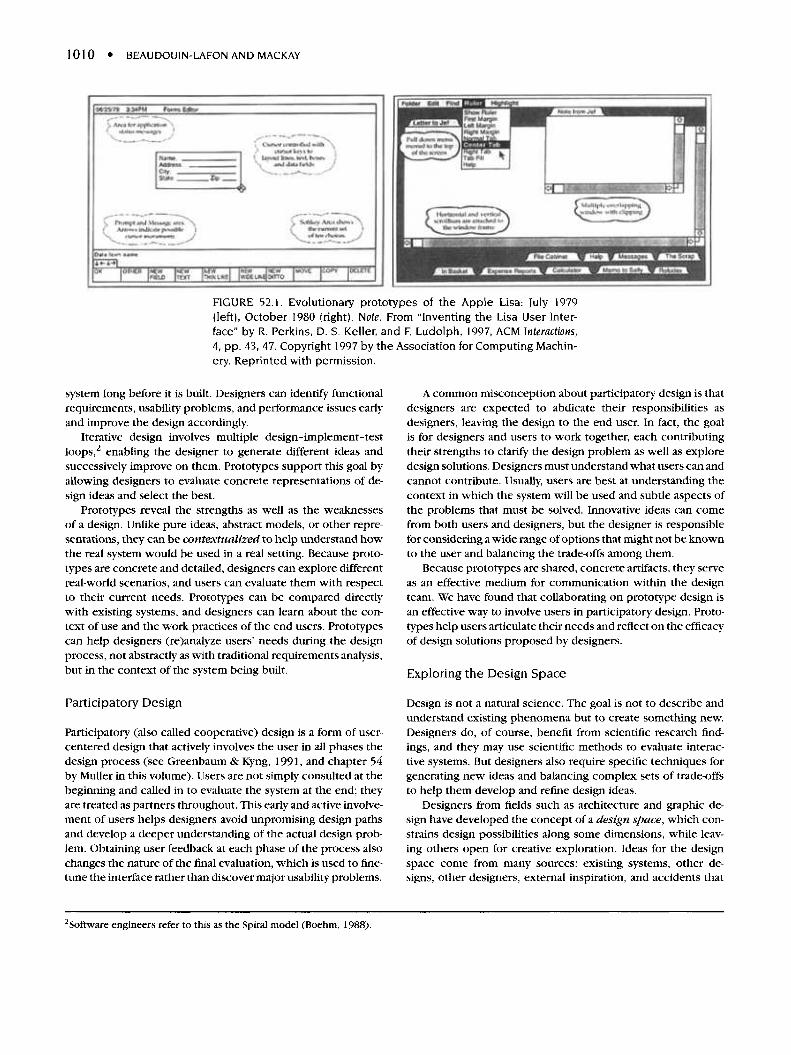
FIGURE 52.1. Evolutionary prototypes of the Apple Lisa: July 1979(left), October 1980 (right). Note. From "Inventing the Lisa User Inter-face" by R. Perkins, D. S. Keller, and F. Ludolph, 1997, ACM Interactions,4, pp. 43, 47. Copyright 1997 by the Association for Computing Machin-ery. Reprinted with permission.
system long before it is built. Designers can identify functionalrequirements, usability problems, and performance issues earlyand improve the design accordingly.
Iterative design involves multiple design-implement-testloops,2 enabling the designer to generate different ideas andsuccessively improve on them. Prototypes support this goal byallowing designers to evaluate concrete representations of de-sign ideas and select the best.
Prototypes reveal the strengths as well as the weaknessesof a design. Unlike pure ideas, abstract models, or other repre-sentations, they can be contextualized to help understand howthe real system would be used in a real setting. Because proto-types are concrete and detailed, designers can explore differentreal-world scenarios, and users can evaluate them with respectto their current needs. Prototypes can be compared directlywith existing systems, and designers can learn about the con-text of use and the work practices of the end users. Prototypescan help designers (re)analyze users' needs during the designprocess, not abstractly as with traditional requirements analysis,but in the context of the system being built.
Participatory Design
Participatory (also called cooperative) design is a form of user-centered design that actively involves the user in all phases thedesign process (see Greenbaum & Kyng, 1991, and chapter 54by Muller in this volume). Users are not simply consulted at thebeginning and called in to evaluate the system at the end; theyare treated as partners throughout. This early and active involve-ment of users helps designers avoid unpromising design pathsand develop a deeper understanding of the actual design prob-lem. Obtaining user feedback at each phase of the process alsochanges the nature of the final evaluation, which is used to fine-tune the interface rather than discover major usability problems.
A common misconception about participatory design is thatdesigners are expected to abdicate their responsibilities asdesigners, leaving the design to the end user. In fact, the goalis for designers and users to work together, each contributingtheir strengths to clarify the design problem as well as exploredesign solutions. Designers must understand what users can andcannot contribute. Usually, users are best at understanding thecontext in which the system will be used and subtle aspects ofthe problems that must be solved. Innovative ideas can comefrom both users and designers, but the designer is responsiblefor considering a wide range of options that might not be knownto the user and balancing the trade-offs among them.
Because prototypes are shared, concrete artifacts, they serveas an effective medium for communication within the designteam. We have found that collaborating on prototype design isan effective way to involve users in participatory design. Proto-types help users articulate their needs and reflect on the efficacyof design solutions proposed by designers.
Exploring the Design Space
Design is not a natural science. The goal is not to describe andunderstand existing phenomena but to create something new.Designers do, of course, benefit from scientific research find-ings, and they may use scientific methods to evaluate interac-tive systems. But designers also require specific techniques forgenerating new ideas and balancing complex sets of trade-offsto help them develop and refine design ideas.
Designers from fields such as architecture and graphic de-sign have developed the concept of a design space, which con-strains design possibilities along some dimensions, while leav-ing others open for creative exploration. Ideas for the designspace come from many sources: existing systems, other de-signs, other designers, external inspiration, and accidents that
2Software engineers refer to this as the Spiral model (Boehm, 1988).
52. Prototyping Tools and Techniques • 1011
prompt new ideas. Designers are responsible for creating a de-sign space specific to a particular design problem. They explorethis design space, expanding and contracting it as they add andeliminate ideas. The process is iterative, more cyclic, than re-ductionist. That is, the designer does not begin with a roughidea and successively add more precise details until the finalsolution is reached. Instead, she begins with a design prob-lem, which imposes set of constraints, and generates a set ofideas to form the initial design space. She then explores thisdesign space, preferably with the user, and selects a particulardesign direction to pursue. This closes off part of the designspace but opens up new dimensions that can be explored. Thedesigner generates additional ideas along these dimensions, ex-plores the expanded design space, and then makes new designchoices. Design principles (e.g., Beaudouin-Lafon & Mackay,2000) help this process by guiding it both in the explorationand choice phases. The process continues, in a cyclic expansionand contraction of the design space, until a satisfying solution isreached.
All designers work with constraints—not just limited bud-gets and programming resources, but also design constraints.These are not necessarily bad; one cannot be creative along alldimensions at once. Some constraints are unnecessary, how-ever, derived from poor framing of the original design problem.If we consider a design space as a set of ideas and a set of con-straints, the designer has two options. She can modify ideaswithin the specified constraints or modify the constraints to en-able new sets of ideas. Unlike traditional engineering, whichtreats the design problem as a given, designers are encouragedto challenge, and if necessary, change the initial design problem.If she reaches an impasse, the designer can either generate newideas or redefine the problem (and thus change the constraints).Some of the most effective design solutions derive from a morecareful understanding and refraining of the design brief.
Note that all members of the design team, including users,may contribute ideas to the design space and help select designdirections from within it. However, it is essential that these twoactivities are kept separate. Expanding the design space requirescreativity and openness to new ideas. During this phase, every-one should avoid criticizing ideas and concentrate on generatingas many as possible. Clever ideas, half-finished ideas, silly ideas,impractical ideas all contribute to the richness of the designspace and improve the quality of the final solution. In contrast,contracting the design space requires critical evaluation of ideas.During this phase, everyone should consider the constraints andweigh the trade-offs. Each major design decision must eliminatepart of the design space: rejecting ideas is necessary to experi-ment and refine others and make progress in the design process.Choosing a particular design direction should spark new sets ofideas, and those new ideas are likely to pose new design prob-lems. In summary, exploring a design space is the process ofmoving back and forth between creativity and choice.
Prototypes aid designers in both aspects of working witha design space: generating concrete representations of newideas and clarifying specific design directions. The next twosubsections describe techniques that have proven most usefulin our own prototyping work, both for research and productdevelopment.
Expanding the Design Space: Generating Ideas
The most well-known idea generation technique is brainstorm-ing, introduced by Osborn (1957). His goal was to create syn-ergy within the members of a group: Ideas suggested by oneparticipant would spark ideas in other participants. Subsequentstudies (Collaros & Anderson, 1969; Diehl & Stroebe, 1987) chal-lenged the effectiveness of group brainstorming, finding that ag-gregates of individuals could produce the same number of ideasas groups. They found certain effects, such as production block-ing, free-riding, and evaluation apprehension, were sufficientto outweigh the benefits of synergy in brainstorming groups.Since then, many researchers have explored different strategiesfor addressing these limitations. For our purposes, the quantityof ideas is not the only important measure: The relationshipsamong members of the group are also important. As de Vreede,Briggs, van Duin, and Enserink (2000) pointed out, one shouldalso consider elaboration of ideas as group members react toeach other's ideas.
We have found that brainstorming, including a variety of vari-ants, is an important group-building exercise in participatory de-sign. Designers may, of course, brainstorm ideas by themselves.But brainstorming in a group is more enjoyable and, if it is arecurring part of the design process, plays an important role inhelping group members share and develop ideas together.
The simplest form of brainstorming involves a small group ofpeople. The goal is to generate as many ideas as possible on a pre-specified topic; quantity not quality, is important. Brainstormingsessions have two phases: The first generates ideas and the sec-ond reflects on those ideas. The initial phase should last no morethan an hour. One person should moderate the session, keep-ing time and ensuring that everyone participates and preventingpeople from critiquing each other's ideas. Discussion should belimited to clarifying the meaning of a particular idea. A secondperson records every idea, usually on a flipchart or transparencyon an overhead projector. After a short break, participants areasked to reread all the ideas, and each person marks their threefavorite ideas.
One variation is designed to ensure that everyone con-tributes, not just those who are verbally dominant. Participantswrite their ideas on individual cards notes for a prespecified pe-riod of time. The moderator then reads each idea aloud. Authorsare encouraged to elaborate (but not justify) their ideas, whichare then posted on a whiteboard or flipchart. Group membersmay continue to generate new ideas, inspired by the others theyhear.
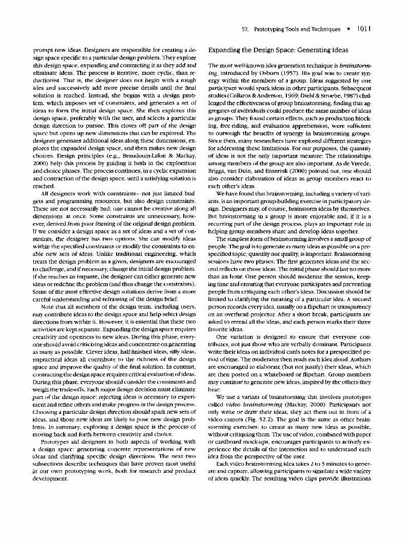
We use a variant of brainstorming that involves prototypescalled video brainstorming (Mackay, 2000): Participants notonly write or draw their ideas, they act them out in front of avideo camera (Fig. 52.2). The goal is the same as other brain-storming exercises: to create as many new ideas as possible,without critiquing them. The use of video, combined with paperor cardboard mock-ups, encourages participants to actively ex-perience the details of the interaction and to understand eachidea from the perspective of the user.
Each video brainstorming idea takes 2 to 5 minutes to gener-ate and capture, allowing participants to simulate a wide varietyof ideas quickly. The resulting video clips provide illustrations
1012 • BEAUDOUIN-LAFON AND MACKAY
FIGURE 52.2. Video brainstorming: One person moves thetransparency, projected onto the wall, in response to the ac-tions of the user, who explores how he might interact with anonline animated character. Each interaction idea is recordedand videotaped.
of each idea that are easier to understand (and remember) thanhand-written notes. (We find that raw notes from brainstormingsessions are not very useful after a few weeks because the par-ticipants no longer remember the context in which the ideaswere created.)
Video brainstorming requires thinking more deeply abouteach idea. It is easier to stay abstract when describing an inter-action in words or even with a sketch, but acting out the interac-tion in front of the camera forces the author of the idea (and theother participants) to consider seriously how a user would inter-act with the idea. It also encourages designers and users to thinkabout new ideas in the context in which they will be used. Videoclips from a video brainstorming session, even though rough,are much easier for the design team, including developers, tointerpret than ideas from a standard brainstorming session.
We generally run a standard brainstorming session, eitheroral or with cards, before a video brainstorming session to max-imize the number of ideas to be explored. Participants then taketheir favorite ideas from the previous session and develop themfurther as video brainstorms. Each person is asked to "direct" atleast two ideas, incorporating the hands or voices of other mem-bers of the group. We find that, unlike standard brainstorming,video brainstorming encourages even the quietest team mem-bers to participate.
Contracting the Design Space: Selecting Alternatives
After expanding the design space by creating new ideas, de-signers must stop and reflect on the choices available to them.After exploring the design space, designers must evaluate theiroptions and make concrete design decisions—choosing someideas, specifically rejecting others, and leaving other aspects ofthe design open to further idea generation activities. Rejecting
good, potentially effective ideas is difficult, but necessary tomake progress.
Prototypes often make it easier to evaluate design ideas fromthe user's perspective. They provide concrete representationsthat can be compared. Many of the evaluation techniques de-scribed elsewhere in this handbook can be applied to proto-types to help focus the design space. The simplest situationis when the designer must choose among several discrete, in-dependent options. Running a simple experiment, using tech-niques borrowed from psychology (see chapter 56 by Dumas)allows the designer to compare how users respond to each ofthe alternatives. The designer builds a prototype, with eitherfully implemented or simulated versions of each option. Thenext step is to construct tasks or activities that are typical ofhow the system would be used, and ask people from the userpopulation to try each of the options under controlled condi-tions. It is important to keep everything the same, except forthe options being tested.
Designers should base their evaluations on both quantitativemeasures, such as speed or error rate, and qualitative measures,such as the user's subjective impressions of each option. Ideally,of course, one design alternative will be clearly faster, prone tofewer errors, and preferred by the majority of users. More often,the results are ambiguous, and the designer must take other fac-tors into account when making the design choice. (Interestingly,running small experiments often highlights other design prob-lems and may help the designer reformulate the design problemor change the design space.)
The more difficult (and common) situation is when the de-signer faces a complex, interacting set of design alternativesin which each design decision affects a number of others. De-signers can use heuristic evaluation techniques, which rely onour understanding of human cognition, memory, and sensory-perception (see chapters 1-6). They can also evaluate their de-signs with respect to ergonomic criteria (see chapter 51 byStewart and Trans) or design principles (Beaudouin-Lafon &Mackay, 2000). (See chapters 56-60 for a more thorough dis-cussion of testing and evaluation methods.)
Another strategy is to create one or more scenarios (seechapter 53 by Rosson and Carroll) that illustrate how the com-bined set of features will be used in a realistic setting. The sce-nario must identify who is involved, where the activities takeplace, and what the user does over a specified period of time.Good scenarios involve more than a string of independent tasks;they should incorporate real-world activities, including com-mon or repeated tasks, successful activities, and breakdownsand errors, with both typical and unusual events. The designerthen creates a prototype that simulates or implements the as-pects of the system necessary to illustrate each set of designalternatives. Such prototypes can be tested by asking users to"walk through" the same scenario several times, once for eachdesign alternative. As with experiments and usability studies,designers can record both quantitative and qualitative data, de-pending on the level of the prototypes being tested.
The previous section described an idea-generation techniquecalled video brainstorming, which allows designers to generatea variety of ideas about how to interact with the future system.We call the corresponding technique for focusing in on a design
52. Prototyping Tools and Techniques • 1013
video prototyping. Video prototyping can incorporate any ofthe rapid-prototyping techniques (offline or online) describedlater. They are quick to build, force designers to consider thedetails of how users will react to the design in the context inwhich it will be used, and provide an inexpensive method ofcomparing complex sets of design decisions.
To an outsider, video brainstorming and video prototyp-ing techniques look very similar. Both involve small designgroups working together, creating rapid prototypes and inter-acting with them in front of a video camera. Both result invideo illustrations that make abstract ideas concrete and helpteam members communicate with each other. The critical dif-ference is that video brainstorming expands the design spaceby creating a number of unconnected collections of individualideas, whereas video prototyping contracts the design spaceby showing how a specific collection of design choices worktogether.
Prototyping Strategies
Designers must decide what role prototypes should play with re-spect to the final system and in which order to create differentaspects of the prototype. The next subsections presents fourstrategies: horizontal, vertical, task-oriented, and scenario-based, which focus on different design concerns. These strate-gies can use any of the prototyping techniques covered in thesections that follow.
Horizontal Prototypes. The purpose of a horizontal proto-type is to develop an entire layer of the design at the same time.This type of prototyping is most common with large softwaredevelopment teams, where designers with different skill setsaddress different layers of the software architecture. Horizontalprototypes of the user interface are useful to get an overall pic-ture of the system from the user's perspective and address issuessuch as consistency (similar functions are accessible throughsimilar user commands), coverage (all required functions aresupported), and redundancy (the same function is/is not acces-sible through different user commands).
User interface horizontal prototypes can begin with rapidprototypes and progress through to working code. Softwareprototypes can be built with an interface builder (discussed laterin the chapter), without creating any of the underlying function-ality, making it possible to test how the user will interact with theuser interface without worrying about how the rest of the archi-tecture works. Some level of scaffolding or simulation of the restof the application is often necessary, however, otherwise theprototype cannot be evaluated properly. As a consequence, soft-ware horizontal prototypes tend to be evolutionary (i.e., theyare progressively transformed into the final system).
Vertical Prototypes. The purpose of a vertical prototype isto ensure that the designer can implement the full, workingsystem from the user interface layer down to the underlyingsystem layer. Vertical prototypes are often built to assess thefeasibility of a feature described in a horizontal, task-oriented,or scenario-based prototype. For example, when we developed
the notion of magnetic guidelines in the CPN2000 system tofacilitate the alignment of graphical objects (Beaudouin-Lafon& Mackay, 2000), we implemented a vertical prototype to testnot only the interaction technique but also the layout algorithmand the performance. We knew that we could only include theparticular interaction technique if the we could implement asufficiently fast response.
Vertical prototypes are generally high precision, softwareprototypes because their goal is to validate an idea at the systemlevel. They are often thrown away because they are generallycreated early in the project, before the overall architecture hasbeen decided, and they focus on only one design question. Forexample, a vertical prototype of a spelling checker for a text ed-itor does not require text editing functions to be implementedand tested. The final version will need to be integrated into therest of the system, however, which may involve considerablearchitectural or interface changes.
Task-Oriented Prototypes. Many user interface designersbegin with a task analysis (see chapter 48 by Redish and Wixon)to identify the individual tasks that the user must accomplishwith the system. Each task requires a corresponding set of func-tionality from the system. Task-based prototypes are organizedas a series of tasks, which allows both designers and users totest each task independently, systematically working throughthe entire system.
Task-oriented prototypes include only the functions neces-sary to implement the specified set of tasks. They combinethe breadth of horizontal prototypes, to cover the functionsrequired by those tasks, with the depth of vertical prototypes,enabling detailed analysis of how the tasks can be supported.Depending on the goal of the prototype, both offline and onlinerepresentations can be used for task-oriented prototypes.
Scenario-Based Prototypes. Scenario-based prototypes aresimilar to task-oriented ones, except that they do not stress in-dividual, independent tasks but rather follow a more realisticscenario of how the system would be used in a real-world set-ting. Scenarios are stories that describe a sequence of eventsand how the user reacts (see chapter 53 by Rosson and Carroll).A good scenario includes both common and unusual situa-tions and should explore patterns of activity over time. B0dker,Christiansen, and Thuring (1995) developed checklist, to ensurethat no important issues have been left out.
We find it useful to begin with use scenarios based on obser-vations of or interviews with real users. Ideally, some of thoseusers should participate in the creation of the specific scenar-ios, and other users should critique them based on how realisticthey are. Use scenarios are then turned into design scenarios, inwhich the same situations are described but with the functional-ity of the new system. Design scenarios are used, among otherthings, to create scenario-based video prototypes or softwareprototypes. Like task-based prototypes, the developer needs towrite only the software necessary to illustrate the componentsof the design scenario. The goal is to create a situation in whichthe user can experience what the system would be like in a re-alistic situation, even if it addresses only a subset of the plannedfunctionality.
1014 • BEAUDOUIN-LAFON AND MACKAY
The following section describes a variety of rapid prototyp-ing techniques that can be used in any of these four prototypingstrategies. We begin with offline rapid prototyping techniques,followed by online prototyping techniques.
RAPID PROTOTYPES
The goal of rapid prototyping is to develop prototypes quickly,in a fraction of the time it would take to develop a working sys-tem. By shortening the prototype-evaluation cycle, the designteam can evaluate more alternatives and iterate the design sev-eral times, improving the likelihood of finding a solution thatsuccessfully meets the user's needs.
How rapid is rapid depends on the context of the particularproject and the stage in the design process. Early prototypes(e.g., sketches) can be created in a few minutes. Later in thedesign cycle, a prototype produced in less than a week maystill be considered "rapid" if the final system is expected to takemonths or years to build. Precision, interactivity, and evolutionall affect the time it takes to create a prototype. Not surprisingly,a precise and interactive prototype takes more time to build thanan imprecise or fixed one.
The techniques presented in this section are organized frommost rapid to least rapid, according to the representation dimen-sion introduced earlier. Offline techniques are generally morerapid than online ones; however, creating successive iterationsof an online prototype may end up being faster than creatingnew offline prototypes.
Offline Rapid Prototyping Techniques
Offline prototyping techniques range from simple to elaborate.Because they do not involve software, they are usually consid-ered a tool for thinking through the design issues, to be thrownaway when they are no longer needed. This section describessimple paper-and-pencil sketches, three-dimensional mock-ups,Wizard-of-Oz simulations, and video prototypes.
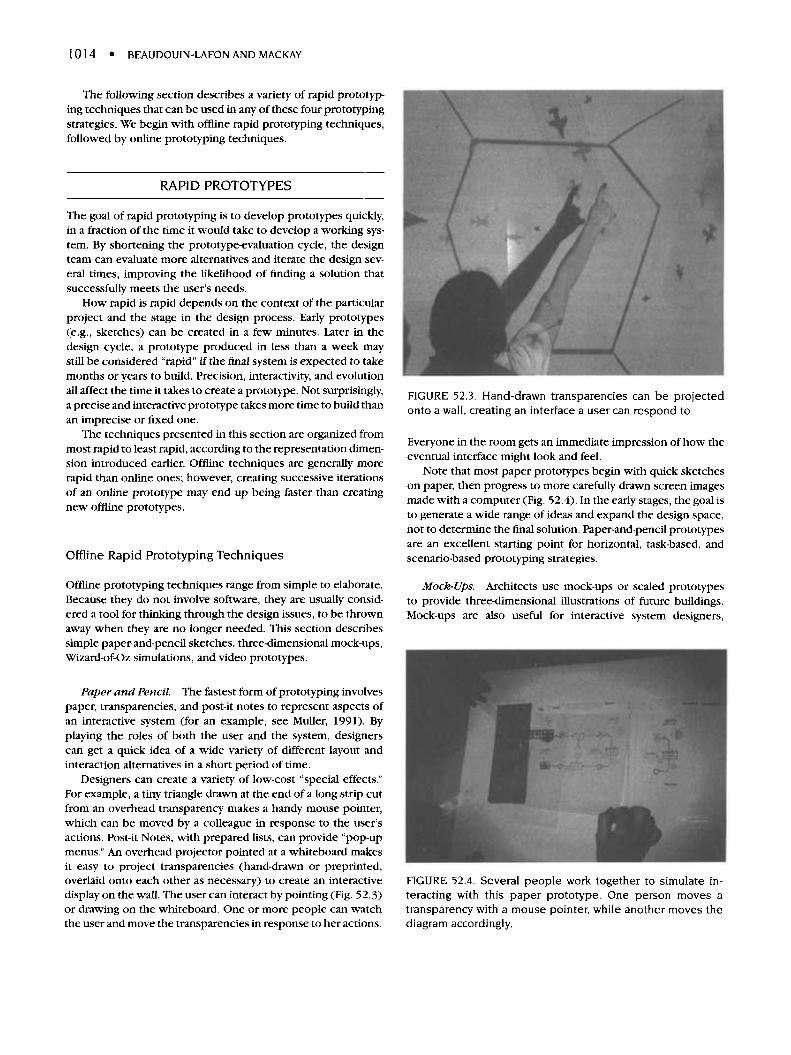
Paper and Pencil. The fastest form of prototyping involvespaper, transparencies, and post-it notes to represent aspects ofan interactive system (for an example, see Muller, 1991). Byplaying the roles of both the user and the system, designerscan get a quick idea of a wide variety of different layout andinteraction alternatives in a short period of time.
Designers can create a variety of low-cost "special effects."For example, a tiny triangle drawn at the end of a long strip cutfrom an overhead transparency makes a handy mouse pointer,which can be moved by a colleague in response to the user'sactions. Post-it Notes, with prepared lists, can provide "pop-upmenus." An overhead projector pointed at a whiteboard makesit easy to project transparencies (hand-drawn or preprinted,overlaid onto each other as necessary) to create an interactivedisplay on the wall. The user can interact by pointing (Fig. 52.3)or drawing on the whiteboard. One or more people can watchthe user and move the transparencies in response to her actions.
FIGURE 52.3. Hand-drawn transparencies can be projectedonto a wall, creating an interface a user can respond to.
Everyone in the room gets an immediate impression of how theeventual interface might look and feel.
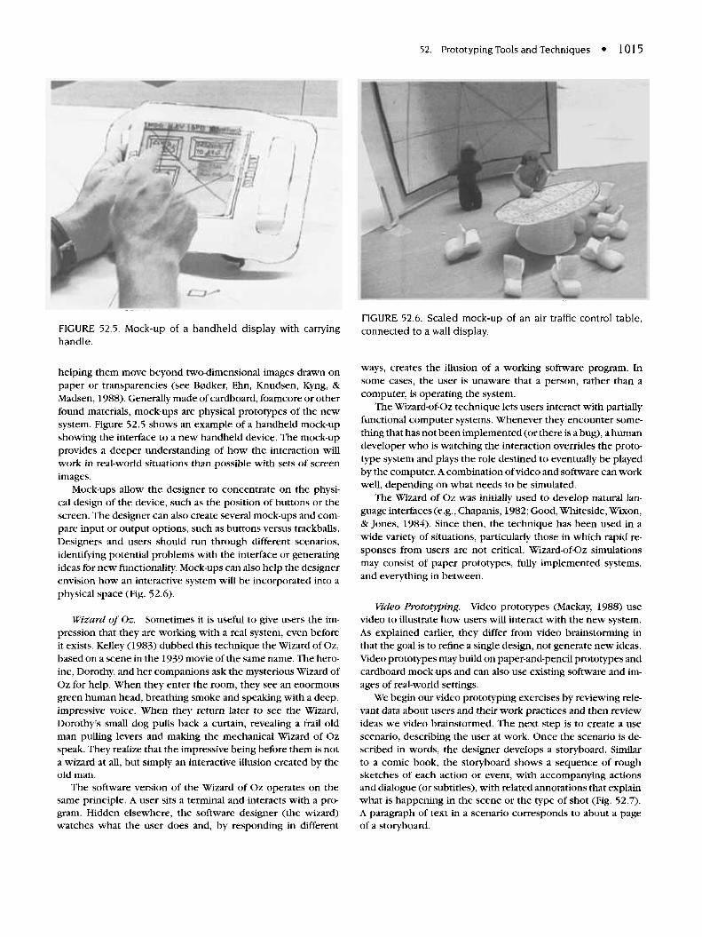
Note that most paper prototypes begin with quick sketcheson paper, then progress to more carefully drawn screen imagesmade with a computer (Fig. 52.4). In the early stages, the goal isto generate a wide range of ideas and expand the design space,not to determine the final solution. Paper-and-pencil prototypesare an excellent starting point for horizontal, task-based, andscenario-based prototyping strategies.
Mock-Ups. Architects use mock-ups or scaled prototypesto provide three-dimensional illustrations of future buildings.Mock-ups are also useful for interactive system designers,
FIGURE 52.4. Several people work together to simulate in-teracting with this paper prototype. One person moves atransparency with a mouse pointer, while another moves thediagram accordingly.
52. Prototyping Tools and Techniques • 1015
FIGURE 52.5. Mock-up of a handheld display with carryinghandle.
helping them move beyond two-dimensional images drawn onpaper or transparencies (see B0dker, Ehn, Knudsen, Kyng, &Madsen, 1988). Generally made of cardboard, foamcore or otherfound materials, mock-ups are physical prototypes of the newsystem. Figure 52.5 shows an example of a handheld mock-upshowing the interface to a new handheld device. The mock-upprovides a deeper understanding of how the interaction willwork in real-world situations than possible with sets of screenimages.
Mock-ups allow the designer to concentrate on the physi-cal design of the device, such as the position of buttons or thescreen. The designer can also create several mock-ups and com-pare input or output options, such as buttons versus trackballs.Designers and users should run through different scenarios,identifying potential problems with the interface or generatingideas for new functionality. Mock-ups can also help the designerenvision how an interactive system will be incorporated into aphysical space (Fig. 52.6).
Wizard of Oz. Sometimes it is useful to give users the im-pression that they are working with a real system, even beforeit exists. Kelley (1983) dubbed this technique the Wizard of Oz,based on a scene in the 1939 movie of the same name. The hero-ine, Dorothy, and her companions ask the mysterious Wizard ofOz for help. When they enter the room, they see an enormousgreen human head, breathing smoke and speaking with a deep,impressive voice. When they return later to see the Wizard,Dorothy's small dog pulls back a curtain, revealing a frail oldman pulling levers and making the mechanical Wizard of Ozspeak. They realize that the impressive being before them is nota wizard at all, but simply an interactive illusion created by theold man.
The software version of the Wizard of Oz operates on thesame principle. A user sits a terminal and interacts with a pro-gram. Hidden elsewhere, the software designer (the wizard)watches what the user does and, by responding in different
FIGURE 52.6. Scaled mock-up of an air traffic control table,connected to a wall display.
ways, creates the illusion of a working software program. Insome cases, the user is unaware that a person, rather than acomputer, is operating the system.
The Wizard-of-Oz technique lets users interact with partiallyfunctional computer systems. Whenever they encounter some-thing that has not been implemented (or there is a bug), a humandeveloper who is watching the interaction overrides the proto-type system and plays the role destined to eventually be playedby the computer. A combination of video and software can workwell, depending on what needs to be simulated.
The Wizard of Oz was initially used to develop natural lan-guage interfaces (e.g., Chapanis, 1982; Good, Whiteside, Wixon,& Jones, 1984). Since then, the technique has been used in awide variety of situations, particularly those in which rapid re-sponses from users are not critical. Wizard-of-Oz simulationsmay consist of paper prototypes, fully implemented systems,and everything in between.
Video Prototyping. Video prototypes (Mackay, 1988) usevideo to illustrate how users will interact with the new system.As explained earlier, they differ from video brainstorming inthat the goal is to refine a single design, not generate new ideas.Video prototypes may build on paper-and-pencil prototypes andcardboard mock-ups and can also use existing software and im-ages of real-world settings.
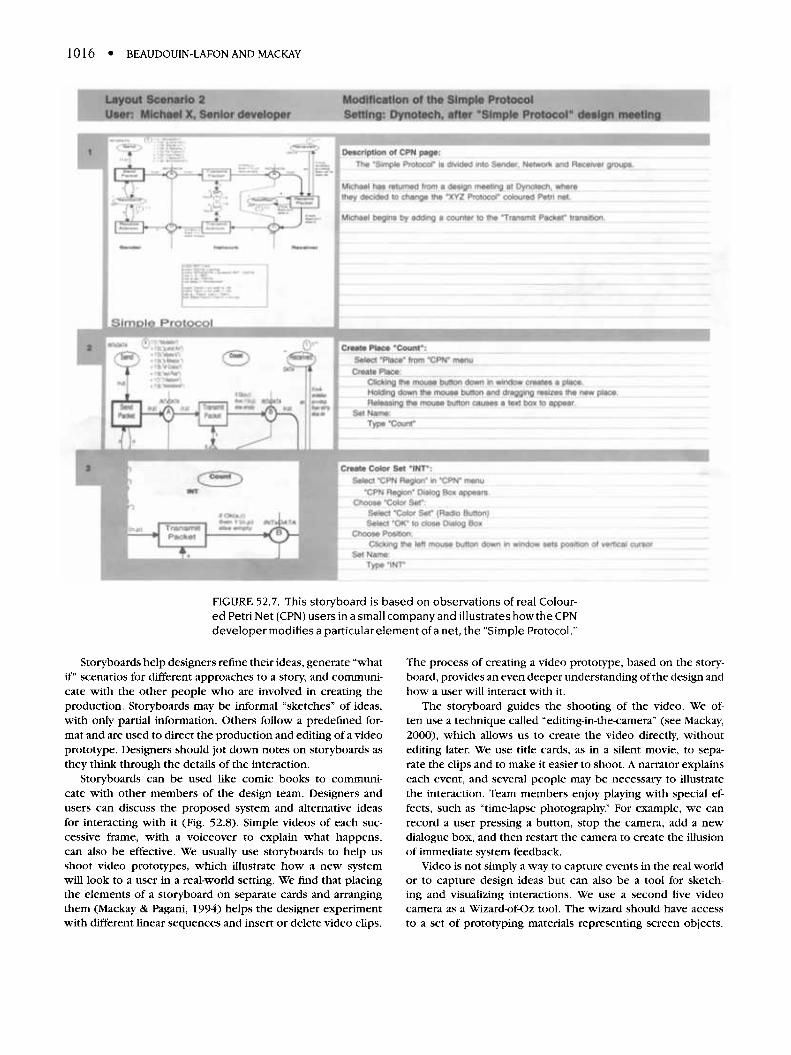
We begin our video prototyping exercises by reviewing rele-vant data about users and their work practices and then reviewideas we video brainstormed. The next step is to create a usescenario, describing the user at work. Once the scenario is de-scribed in words, the designer develops a storyboard. Similarto a comic book, the storyboard shows a sequence of roughsketches of each action or event, with accompanying actionsand dialogue (or subtitles), with related annotations that explainwhat is happening in the scene or the type of shot (Fig. 52.7).A paragraph of text in a scenario corresponds to about a pageof a storyboard.
1016 • BEAUDOUIN-LAFON AND MACKAY
FIGURE 52.7. This storyboard is based on observations of real Colour-ed Petri Net (CPN) users in a small company and illustrates how the CPNdeveloper modifies a particular element of a net, the "Simple Protocol."
Storyboards help designers refine their ideas, generate "whatif" scenarios for different approaches to a story, and communi-cate with the other people who are involved in creating theproduction. Storyboards may be informal "sketches" of ideas,with only partial information. Others follow a predefined for-mat and are used to direct the production and editing of a videoprototype. Designers should jot down notes on Storyboards asthey think through the details of the interaction.
Storyboards can be used like comic books to communi-cate with other members of the design team. Designers andusers can discuss the proposed system and alternative ideasfor interacting with it (Fig. 52.8). Simple videos of each suc-cessive frame, with a voiceover to explain what happens,can also be effective. We usually use Storyboards to help usshoot video prototypes, which illustrate how a new systemwill look to a user in a real-world setting. We find that placingthe elements of a storyboard on separate cards and arrangingthem (Mackay & Pagani, 1994) helps the designer experimentwith different linear sequences and insert or delete video clips.
The process of creating a video prototype, based on the story-board, provides an even deeper understanding of the design andhow a user will interact with it.
The storyboard guides the shooting of the video. We of-ten use a technique called "editing-in-the-camera" (see Mackay,2000), which allows us to create the video directly, withoutediting later. We use title cards, as in a silent movie, to sepa-rate the clips and to make it easier to shoot. A narrator explainseach event, and several people may be necessary to illustratethe interaction. Team members enjoy playing with special ef-fects, such as "time-lapse photography." For example, we canrecord a user pressing a button, stop the camera, add a newdialogue box, and then restart the camera to create the illusionof immediate system feedback.
Video is not simply a way to capture events in the real worldor to capture design ideas but can also be a tool for sketch-ing and visualizing interactions. We use a second live videocamera as a Wizard-of-Oz tool. The wizard should have accessto a set of prototyping materials representing screen objects.
52. Prototyping Tools and Techniques • 1017
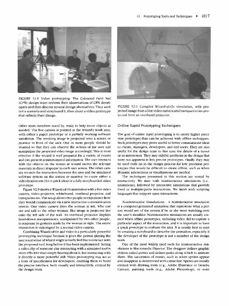
FIGURE 52.8. Video prototyping: The Coloured Petri Net(CPN) design team reviews their observations of CPN devel-opers and then discuss several design alternatives. They workout a scenario and storyboard it, then shoot a video prototypethat reflects their design.
Other team members stand by, ready to help move objects asneeded. The live camera is pointed at the wizard's work area,with either a paper prototype or a partially working softwaresimulation. The resulting image is projected onto a screen ormonitor in front of the user. One or more people should besituated so that they can observe the actions of the user andmanipulate the projected video image accordingly. This is mosteffective if the wizard is well prepared for a variety of eventsand can present semiautomated information. The user interactswith the objects on the screen as wizard moves the relevantmaterials in direct response to each user action. The other cam-era records the interaction between the user and the simulatedsoftware system on the screen or monitor, to create either avideo brainstorm (for a quick idea) or a fully storyboarded videoprototype.
Figure 52.9 shows a Wizard-of-Oz simulation with a live videocamera, video projector, whiteboard, overhead projector, andtransparencies. The setup allows two people to experience howthey would communicate via a new interactive communicationsystem. One video camera films the woman at left, who cansee and talk to the other woman. Her image is projected liveonto the left side of the wall. An overhead projector displayshand-drawn transparencies, manipulated by two other people,in response to gestures made by the woman at right. The entireinteraction is videotaped by a second video camera.
Combining Wizard-of-Oz and video is a particularly powerfulprototyping technique because it gives the person playing theuser a real sense of what it might actually feel like to interact withthe proposed tool, long before it has been implemented. Seeinga video clip of someone else interacting with a simulated tool ismore effective than simply hearing about it, but interacting withit directly is more powerful still. Video prototyping may act asa form of specification for developers, enabling them to buildthe precise interface, both visually and interactively, created bythe design team.
FIGURE 52.9. Complex Wizard-of-Oz simulation, with pro-jected image from a live video camera and transparencies pro-jected from an overhead projector.
Online Rapid Prototyping Techniques
The goal of online rapid prototyping is to create higher preci-sion prototypes than can be achieved with offline techniques.Such prototypes may prove useful to better communicate ideasto clients, managers, developers, and end users. They are alsouseful for the design team to fine tune the details of a layoutor an interaction. They may exhibit problems in the design thatwere not apparent in less precise prototypes. Finally, they maybe used early on in the design process for low precision pro-totypes that would be difficult to create offline, such as whendynamic interactions or visualizations are needed.
The techniques presented in this section are sorted byinteractivity. We start with noninteractive simulations (i.e.,animations), followed by interactive simulations that providefixed or multiple-paths interactions. We finish with scriptinglanguages that support open interactions.
Noninteractive Simulations, A noninteractive simulationis a computer-generated animation that represents what a per-son would see of the system if he or she were watching overthe user's shoulder. Noninteractive simulations are usually cre-ated when offline prototypes, including video, fail to capture aparticular aspect of the interaction, and it is important to havea quick prototype to evaluate the idea. It is usually best to startby creating a storyboard to describe the animation, especially ifthe developer of the prototype is not a member of the designteam.
One of the most widely used tools for noninteractive sim-ulations is Macromedia Director. The designer defines graphicobjects called sprites and defines paths along which to animatethem. The succession of events, such as when sprites appearand disappear, is determined with a time line. Sprites are usuallycreated with drawing tools (e.g., Adobe Illustrator or DenebaCanvas), painting tools (e.g., Adobe Photoshop), or even
1018 • BEAUDOUIN-LAFON AND MACKAY
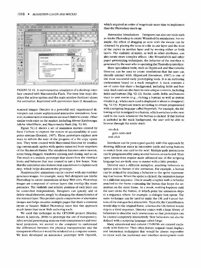
FIGURE 52.10. A noninteractive simulation of a desktop inter-face created with Macromedia Flash. The time line (top) dis-plays the active sprites and the main window (bottom) showsthe animation. Reprinted with permission from O. Beaudoux.
scanned images. Director is a powerful tool; experienced de-velopers can create sophisticated interactive simulations; how-ever, noninteractive simulations are much faster to create. Othersimilar tools exist on the market, including Abvent Katabounga,Adobe AfterEffects, and Macromedia Flash (Fig. 52.10).
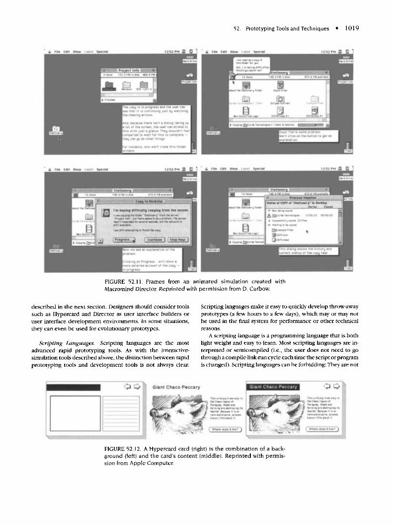
Figure 52.11 shows a set of animation movies created byDave Curbow to explore the notion of accountability in com-puter systems (Dourish, 1997). These prototypes explore newways to inform the user of the progress of a file copy opera-tion. They were created with Macromind Director by combin-ing custom-made sprites with sprites extracted from snapshotsof the Macintosh Finder. The simulation features cursor motion,icons being dragged, windows opening and closing, and so on.The result is a realistic prototype that shows how the interfacelooks and behaves that was created in just a few hours. Notethat the simulation also features text annotations to explain eachstep, which helps document the prototype.
Noninteractive animations can be created with any tool thatgenerates images. For example, many Web designers use AdobePhotoshop to create simulations of their Web sites. Photoshopimages are composed of various layers that overlap like trans-parencies. The visibility and relative position of each layer canbe controlled independently. Designers can quickly add ordelete visual elements, simply by changing the characteristics ofthe relevant layer. This permits quick comparisons of alternativedesigns and helps visualize multiple pages that share a commonlayout or banner. Skilled Photoshop users find this approachmuch faster than most Web authoring tools.
We used this technique in the CPN2000 project (Mackay,Ratzer, & Janecek, 2000) to prototype the use of transparency.After several prototyping sessions with transparencies and over-head projectors, we moved to the computer to understandthe differences between the physical transparencies and thetransparent effect as it would be rendered on a computer screen.We later developed an interactive prototype with OpenGL,
which required an order of magnitude more time to implementthan the Photoshop mock-up.
Interactive Simulations. Designers can also use tools suchas Adobe Photoshop to create Wizard-of-Oz simulations. For ex-ample, the effect of dragging an icon with the mouse can beobtained by placing the icon of a file in one layer and the iconof the cursor in another layer and by moving either or bothlayers. The visibility of layers, as well as other attributes, canalso create more complex effects. Like Wizard-of-Oz and otherpaper prototyping techniques, the behavior of the interface isgenerated by the user who is operating the Photoshop interface.
More specialized tools, such as HyperCard and MacromediaDirector, can be used to create simulations that the user candirectly interact with. HyperCard (Goodman, 1987) is one ofthe most successful early prototyping tools. It is an authoringenvironment based on a stack metaphor: A stack contains aset of cards that share a background, including fields and but-tons. Each card can also have its own unique contents, includingfields and buttons (Fig. 52.12). Stacks, cards, fields, and buttonsreact to user events (e.g., clicking a button) as well as systemevents (e.g., when a new card is displayed or about to disappear;Fig. 52.13). HyperCard reacts according to events programmedwith a scripting language called Hypertalk. For example, the fol-lowing script is assigned to a button, which switches to the nextcard in the stack whenever the button is clicked. If this buttonis included in the stack background, the user will be able tobrowse through the entire stack:
on clickgoto next card
end click
Interfaces can be prototyped quickly with this approach bydrawing different states in successive cards and using buttonsto switch from one card to the next. Multiple-path interactionscan be programmed by using several buttons on each card. Moreopen interactions require more advanced use of the scriptinglanguage but are fairly easy to master with a little practice.
Director uses a different metaphor, attaching behaviors tosprites and to frames of the animation. For example, a buttoncan be defined by attaching a behavior to the sprite represent-ing that button. When the sprite is clicked, the animation jumpsto a different sequence. This is usually coupled with a behaviorattached to the frame containing the button that loops the an-imation on the same frame. As a result, nothing happens untilthe user clicks the button, at which point the animation skipsto a sequence where, for example, a dialogue box opens. Thesame technique can be used to make the OK and Cancel but-tons of the dialogue box interactive. Typically, the Cancel buttonwould skip to the original frame, whereas the OK button wouldskip to a third sequence. Director comes with a large library ofbehaviors to describe such interactions so that prototypes canbe created completely interactively. New behaviors can also bedefined with a scripting language called Lingo.
Many educational and cultural CD-ROMs are created exclu-sively with Director. They often feature original visual displaysand interaction techniques that would be almost impossibleto create with the traditional user interface development tools
52. Prototyping Tools and Techniques • 1019
FIGURE 52.11. Frames from an animated simulation created withMacromind Director. Reprinted with permission from D. Curbow.
described in the next section. Designers should consider toolssuch as HyperCard and Director as user interface builders oruser interface development environments. In some situations,they can even be used for evolutionary prototypes.
Scripting Languages. Scripting languages are the mostadvanced rapid prototyping tools. As with the interactive-simulation tools described above, the distinction between rapidprototyping tools and development tools is not always clear.
Scripting languages make it easy to quickly develop throw-awayprototypes (a few hours to a few days), which may or may notbe used in the final system for performance or other technicalreasons.
A scripting language is a programming language that is bothlight weight and easy to learn. Most scripting languages are in-terpreted or semicompiled (i.e., the user does not need to gothrough a compile-link-run cycle each time the script or programis changed). Scripting languages can be forbidding: They are not
FIGURE 52.12. A HyperCard card (right) is the combination of a back-ground (left) and the card's content (middle). Reprinted with permis-sion from Apple Computer.
1020 • BEAUDOUIN-LAFON AND MACKAY
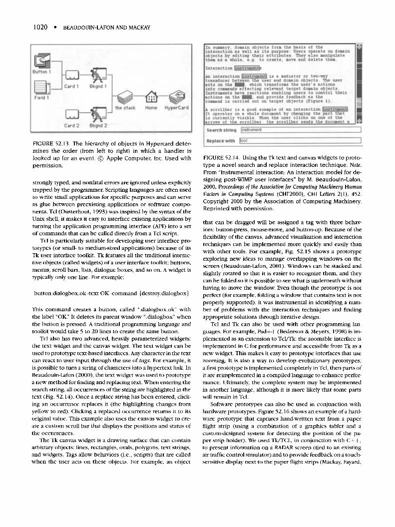
FIGURE 52.13. The hierarchy of objects in HyperCard deter-mines the order (from left to right) in which a handler islooked up for an event. © Apple Computer, Inc. Used withpermission.
strongly typed, and nonfatal errors are ignored unless explicitlytrapped by the programmer. Scripting languages are often usedto write small applications for specific purposes and can serveas glue between preexisting applications or software compo-nents. Tcl (Ousterhout, 1993) was inspired by the syntax of theUnix shell, it makes it easy to interface existing applications byturning the application programming interface (API) into a setof commands that can be called directly from a Tcl script.
Tcl is particularly suitable for developing user interface pro-totypes (or small- to medium-sized applications) because of itsTk user interface toolkit. Tk features all the traditional interac-tive objects (called widgets) of a user interface toolkit: buttons,menus, scroll bars, lists, dialogue boxes, and so on. A widget istypically only one line. For example:
button.dialogbox.ok -text OK -command {destroy.dialogbox}
This command creates a button, called ".dialogbox.ok" withthe label "OK." It deletes its parent window ".dialogbox" whenthe button is pressed. A traditional programming language andtoolkit would take 5 to 20 lines to create the same button.
Tcl also has two advanced, heavily parameterized widgets:the text widget and the canvas widget. The text widget can beused to prototype text-based interfaces. Any character in the textcan react to user input through the use of tags. For example, itis possible to turn a string of characters into a hypertext link. InBeaudouin-Lafon (2000), the text widget was used to prototypea new method for finding and replacing text. When entering thesearch string, all occurrences of the string are highlighted in thetext (Fig. 52.14). Once a replace string has been entered, click-ing an occurrence replaces it (the highlighting changes fromyellow to red). Clicking a replaced occurrence returns it to itsoriginal value. This example also uses the canvas widget to cre-ate a custom scroll bar that displays the positions and status ofthe occurrences.
The Tk canvas widget is a drawing surface that can containarbitrary objects: lines, rectangles, ovals, polygons, text strings,and widgets. Tags allow behaviors (i.e., scripts) that are calledwhen the user acts on these objects. For example, an object
FIGURE 52.14. Using the Tk text and canvas widgets to proto-type a novel search and replace interaction technique. Note.From "Instrumental interaction: An interaction model for de-signing post-WIMP user interfaces" by M. Beaudouin-Lafon,2000, Proceedings of the Association for Computing Machinery HumanFactors in Computing Systems (CHI'2000), CHI Letters 2(1), 452.Copyright 2000 by the Association of Computing Machinery.Reprinted with permission.
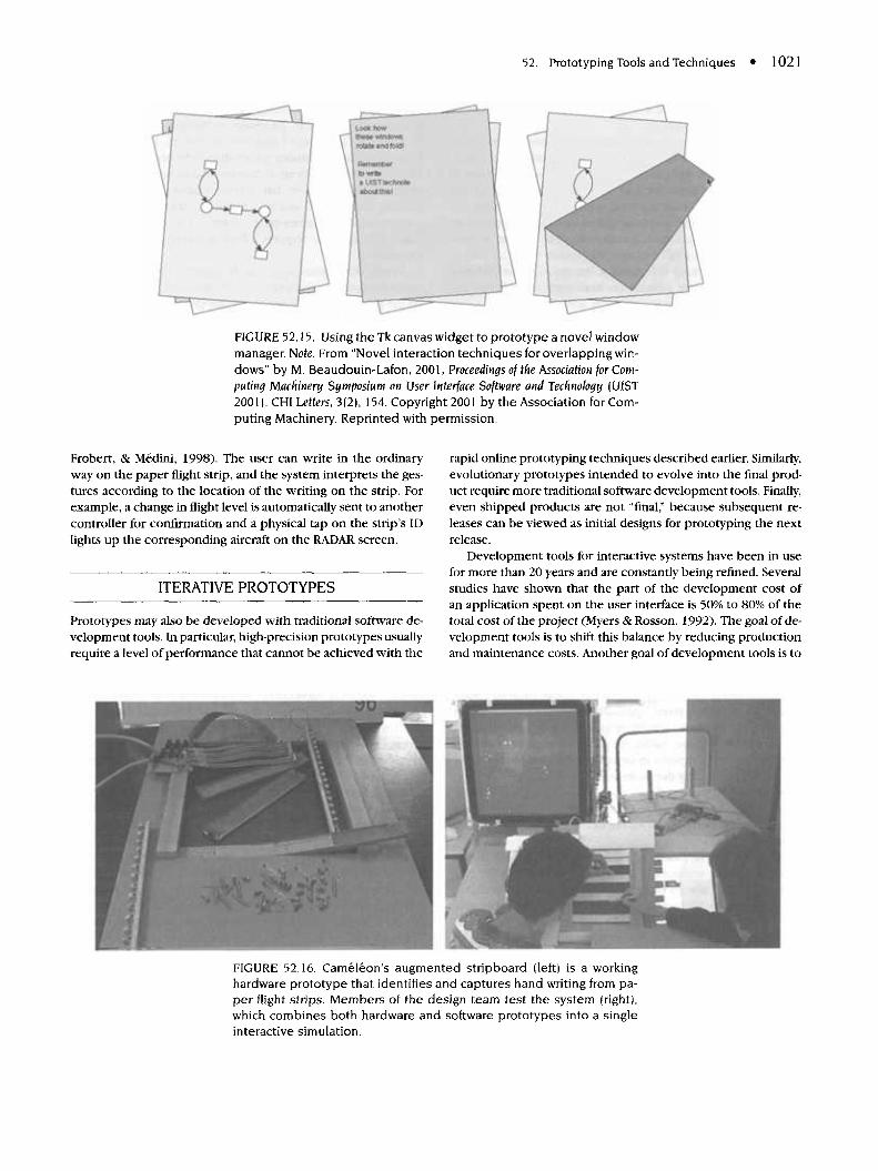
that can be dragged will be assigned a tag with three behav-iors: button-press, mouse-move, and button-up. Because of theflexibility of the canvas, advanced visualization and interactiontechniques can be implemented more quickly and easily thanwith other tools. For example, Fig. 52.15 shows a prototypeexploring new ideas to manage overlapping windows on thescreen (Beaudouin-Lafon, 2001). Windows can be stacked andslightly rotated so that it is easier to recognize them, and theycan be folded so it is possible to see what is underneath withouthaving to move the window. Even though the prototype is notperfect (for example, folding a window that contains text is notproperly supported), it was instrumental in identifying a num-ber of problems with the interaction techniques and findingappropriate solutions through iterative design.
Tcl and Tk can also be used with other programming lan-guages. For example, Pad++ (Bederson & Meyers, 1998) is im-plemented as an extension to Tcl/Tk: the zoomable interface isimplemented in C for performance and accessible from Tk as anew widget. This makes it easy to prototype interfaces that usezooming. It is also a way to develop evolutionary prototypes:a first prototype is implemented completely in Tcl, then parts ofit are reimplemented in a compiled language to enhance perfor-mance. Ultimately, the complete system may be implementedin another language, although it is more likely that some partswill remain in Tcl.
Software prototypes can also be used in conjunction withhardware prototypes. Figure 52.16 shows an example of a hard-ware prototype that captures hand-written text from a paperflight strip (using a combination of a graphics tablet and acustom-designed system for detecting the position of the pa-per strip holder). We used Tk/TCL, in conjunction with C++,to present information on a RADAR screen (tied to an existingair traffic control simulator) and to provide feedback on a touch-sensitive display next to the paper flight strips (Mackay, Fayard,
52. Prototyping Tools and Techniques • 1021
FIGURE 52.15. Using the Tk canvas widget to prototype a novel windowmanager. Note. From "Novel interaction techniques for overlapping win-dows" by M. Beaudouin-Lafon, 2001, Proceedings of the Association for Com-puling Machinery Symposium on User Interface Software and Technology (UIST2001). CHI Letters, 3(2), 154. Copyright 2001 by the Association for Com-puting Machinery. Reprinted with permission.
Frobert, & Medini, 1998). The user can write in the ordinaryway on the paper flight strip, and the system interprets the ges-tures according to the location of the writing on the strip. Forexample, a change in flight level is automatically sent to anothercontroller for confirmation and a physical tap on the strip's IDlights up the corresponding aircraft on the RADAR screen.
ITERATIVE PROTOTYPES
Prototypes may also be developed with traditional software de-velopment tools. In particular, high-precision prototypes usuallyrequire a level of performance that cannot be achieved with the
rapid online prototyping techniques described earlier. Similarly,evolutionary prototypes intended to evolve into the final prod-uct require more traditional software development tools. Finally,even shipped products are not "final," because subsequent re-leases can be viewed as initial designs for prototyping the nextrelease.
Development tools for interactive systems have been in usefor more than 20 years and are constantly being refined. Severalstudies have shown that the part of the development cost ofan application spent on the user interface is 50% to 80% of thetotal cost of the project (Myers & Rosson, 1992). The goal of de-velopment tools is to shift this balance by reducing productionand maintenance costs. Another goal of development tools is to
FIGURE 52.16. Cameleon's augmented stripboard (left) is a workinghardware prototype that identifies and captures hand writing from pa-per flight strips. Members of the design team test the system (right),which combines both hardware and software prototypes into a singleinteractive simulation.
1022 • BEAUDOUIN-LAFON AND MACKAY
anticipate the evolution of the system over successive releasesand support iterative design.
Interactive systems are inherently more powerful than non-interactive ones (see Wegner, 1997, for a theoretical argument).They do not match the traditional, purely algorithmic, type ofprogramming: An interactive system must handle user input andgenerate output at almost any time, whereas an algorithmic sys-tem reads input at the beginning, processes it, and displays re-sults at the end. In addition, interactive systems must processinput and output at rates that are compatible with the humanperception-action loop (i.e., in time frames of 20 to 200 ms).In practice, interactive systems are both reactive and real-timesystems, two active areas in computer science research.
The need to develop interactive systems more efficiently hasled to two interrelated streams of work. The first involves cre-ation of software tools, from low-level user interface librariesand toolkits to high-level user interface development environ-ments (UIDE). The second addresses software architectures forinteractive systems, or how system functions are mapped ontosoftware modules. The rest of this section presents the mostsalient contributions of these two streams of work.
Software Tools
Since the advent of graphical user interfaces in the 1980s, alarge number of tools have been developed to help with thecreation of interactive software, most aimed at visual interfaces.This section presents a collection of tools, from low-level (i.e.,requiring a lot of programming) to high-level tools.
The lowest level tools are graphical libraries that providehardware independence for painting pixels on a screen andhandling user input, and window systems that provide an ab-straction (the window) to structure the screen into several"virtual terminals." User interface toolkits structure an inter-face as a tree of interactive objects called widgets, whereas userinterface builders provide an interactive application to createand edit those widget trees. Application frameworks build ontoolkits and UI builders to facilitate creation of typical functionssuch as cut/copy/paste, undo, help, and interfaces based onediting multiple documents in separate windows. Model-basedtools semiautomatically derive an interface from a specificationof the domain objects and functions to be supported. Finally,user interface development environments or UIDEs provide anintegrated collection of tools for the development of interactivesoftware.
Before we describe each of these categories in more detail,it is important to understand how they can be used for pro-totyping. It is not always best to use the highest-level availabletool. High-level tools are most valuable in the long term becausethey make it easier to maintain the system, port it to variousplatforms, or localize it to different languages. These issues areirrelevant for vertical and throw-away prototypes, so a high-leveltool may prove less effective than a lower level one.
The main disadvantage of higher level tools is that they con-strain or stereotype the types of interfaces they can implement.User interface toolkits usually contain a limited set of "widgets,"and it is expensive to create new ones. If the design must
incorporate new interaction techniques, such as bimanual in-teraction (Kurtenbach, Fitzmaurice, Baudel, & Buxton, 1997)or zoomable interfaces (Bederson & Hollan, 1994), a user in-terface toolkit will hinder rather than help prototype develop-ment. Similarly, application frameworks assume a stereotypedapplication with a menu bar, several toolbars, a set of windowsholding documents, and so on. Such a framework would beinappropriate for developing a game or a multimedia educa-tional CD-ROM that requires a fluid, dynamic, and original userinterface.
Finally, developers need to truly master these tools, especiallywhen prototyping in support of a design team. Success dependson the programmer's ability to quickly change the details as wellas the overall structure of the prototype. A developer will bemore productive when using a familiar tool than if forced to usea more powerful but unknown tool.
Graphical Libraries and Window Systems. Graphical li-braries underlie all the other tools presented in this section.Their main purpose is to provide the developer with a hardware-independent, and sometimes cross-platform application pro-gramming interface (API) for drawing on the screen. They canbe separated into two categories: direct drawing and scene-graph based. Direct drawing libraries provide functions to drawshapes on the screen once their geometry and their graphicalattributes are specified. This means that every time somethingis to be changed on the display, the programmer has to eitherredraw the whole screen or figure out exactly which parts havechanged. Xlib on Unix systems, Quickdraw on MacOS, Win32GDI on Windows, and OpenGL (Woo, Neider, & Davis, 1997)on all three platforms are all direct drawing libraries. They offerthe best compromise between performance and flexibility butare difficult to program.
Scene-graph based libraries explicitly represent the contentsof the display by a structure called a scene graph. It can be a sim-ple list (called display list), a tree (as used by many user interfacetoolkits; see next subsection), or a direct acyclic graph (DAG).Rather than painting on the screen, the developer creates andupdates the scene graph, and the library is responsible for up-dating the screen to reflect the scene graph. Scene graphs aremostly used for three-dimensional graphics (e.g., OpenInven-tor, Strass, 1993), but in recent years they have also been usedfor two-dimensional graphics (Beaudouin-Lafon & Lassen, 2000;Bederson et al., 2000). With the advent of hardware-acceleratedgraphics cards, scene-graph based graphics libraries can offeroutstanding performance while easing the task of the developer.
Window systems provide an abstraction to allow multipleclient applications to share the same screen. Applications createwindows and draw into them. From the application perspective,windows are independent and behave as separate screens. Allgraphical libraries include or interface with a window system.Window systems also offer a user interface to manipulate win-dows (move, resize, close, change stacking order, etc.) calledthe window manager. The window manager may be a separateapplication (as in X-Windows), it may be built into the windowsystem (as in Windows), or it may be controlled of each appli-cation (as in MacOS). Each solution offers a different trade-offbetween flexibility and programming cost.
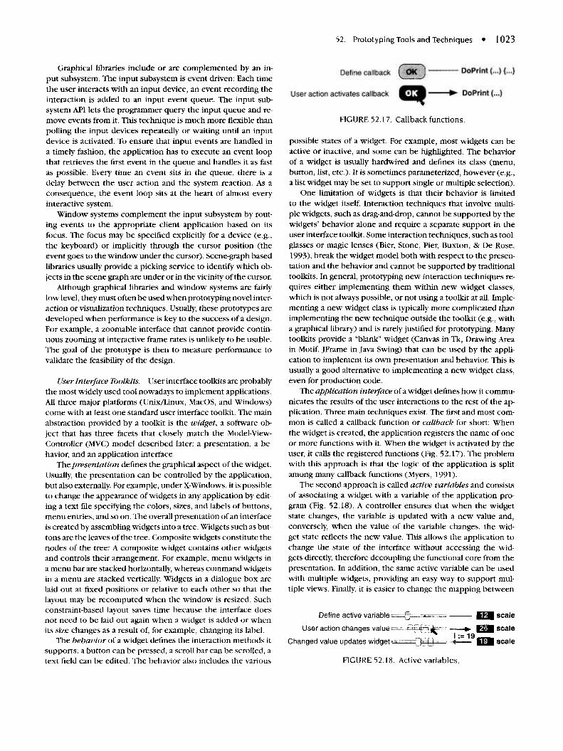
52. Prototyping Tools and Techniques • 1023
Graphical libraries include or are complemented by an in-put subsystem. The input subsystem is event driven: Each timethe user interacts with an input device, an event recording theinteraction is added to an input event queue. The input sub-system API lets the programmer query the input queue and re-move events from it. This technique is much more flexible thanpolling the input devices repeatedly or waiting until an inputdevice is activated. To ensure that input events are handled ina timely fashion, the application has to execute an event loopthat retrieves the first event in the queue and handles it as fastas possible. Every time an event sits in the queue, there is adelay between the user action and the system reaction. As aconsequence, the event loop sits at the heart of almost everyinteractive system.
Window systems complement the input subsystem by rout-ing events to the appropriate client application based on itsfocus. The focus may be specified explicitly for a device (e.g.,the keyboard) or implicitly through the cursor position (theevent goes to the window under the cursor). Scene-graph basedlibraries usually provide a picking service to identify which ob-jects in the scene graph are under or in the vicinity of the cursor.
Although graphical libraries and window systems are fairlylow level, they must often be used when prototyping novel inter-action or visualization techniques. Usually, these prototypes aredeveloped when performance is key to the success of a design.For example, a zoomable interface that cannot provide contin-uous zooming at interactive frame rates is unlikely to be usable.The goal of the prototype is then to measure performance tovalidate the feasibility of the design.
User Interface Toolkits. User interface toolkits are probablythe most widely used tool nowadays to implement applications.All three major platforms (Unix/Linux, MacOS, and Windows)come with at least one standard user interface toolkit. The mainabstraction provided by a toolkit is the widget, a software ob-ject that has three facets that closely match the Model-View-Controller (MVC) model described later: a presentation, a be-havior, and an application interface.
The presentation defines the graphical aspect of the widget.Usually, the presentation can be controlled by the application,but also externally. For example, under X-Windows, it is possibleto change the appearance of widgets in any application by edit-ing a text file specifying the colors, sizes, and labels of buttons,menu entries, and so on. The overall presentation of an interfaceis created by assembling widgets into a tree. Widgets such as but-tons are the leaves of the tree. Composite widgets constitute thenodes of the tree: A composite widget contains other widgetsand controls their arrangement. For example, menu widgets ina menu bar are stacked horizontally, whereas command widgetsin a menu are stacked vertically. Widgets in a dialogue box arelaid out at fixed positions or relative to each other so that thelayout may be recomputed when the window is resized. Suchconstraint-based layout saves time because the interface doesnot need to be laid out again when a widget is added or whenits size changes as a result of, for example, changing its label.
The behavior of a widget defines the interaction methods itsupports: a button can be pressed, a scroll bar can be scrolled, atext field can be edited. The behavior also includes the various
FIGURE 52.17. Callback functions.
possible states of a widget. For example, most widgets can beactive or inactive, and some can be highlighted. The behaviorof a widget is usually hardwired and defines its class (menu,button, list, etc.). It is sometimes parameterized, however (e.g.,a list widget may be set to support single or multiple selection).
One limitation of widgets is that their behavior is limitedto the widget itself. Interaction techniques that involve multi-ple widgets, such as drag-and-drop, cannot be supported by thewidgets' behavior alone and require a separate support in theuser interface toolkit. Some interaction techniques, such as tool-glasses or magic lenses (Bier, Stone, Pier, Buxton, & De Rose,1993), break the widget model both with respect to the presen-tation and the behavior and cannot be supported by traditionaltoolkits. In general, prototyping new interaction techniques re-quires either implementing them within new widget classes,which is not always possible, or not using a toolkit at all. Imple-menting a new widget class is typically more complicated thanimplementing the new technique outside the toolkit (e.g., witha graphical library) and is rarely justified for prototyping. Manytoolkits provide a "blank" widget (Canvas in Tk, Drawing Areain Motif, JFrame in Java Swing) that can be used by the appli-cation to implement its own presentation and behavior. This isusually a good alternative to implementing a new widget class,even for production code.
The application interface of a widget defines how it commu-nicates the results of the user interactions to the rest of the ap-plication. Three main techniques exist. The first and most com-mon is called a callback function or callback for short: Whenthe widget is created, the application registers the name of oneor more functions with it. When the widget is activated by theuser, it calls the registered functions (Fig. 52.17). The problemwith this approach is that the logic of the application is splitamong many callback functions (Myers, 1991).
The second approach is called active variables and consistsof associating a widget with a variable of the application pro-gram (Fig. 52.18). A controller ensures that when the widgetstate changes, the variable is updated with a new value and,conversely, when the value of the variable changes, the wid-get state reflects the new value. This allows the application tochange the state of the interface without accessing the wid-gets directly, therefore decoupling the functional core from thepresentation. In addition, the same active variable can be usedwith multiple widgets, providing an easy way to support mul-tiple views. Finally, it is easier to change the mapping between
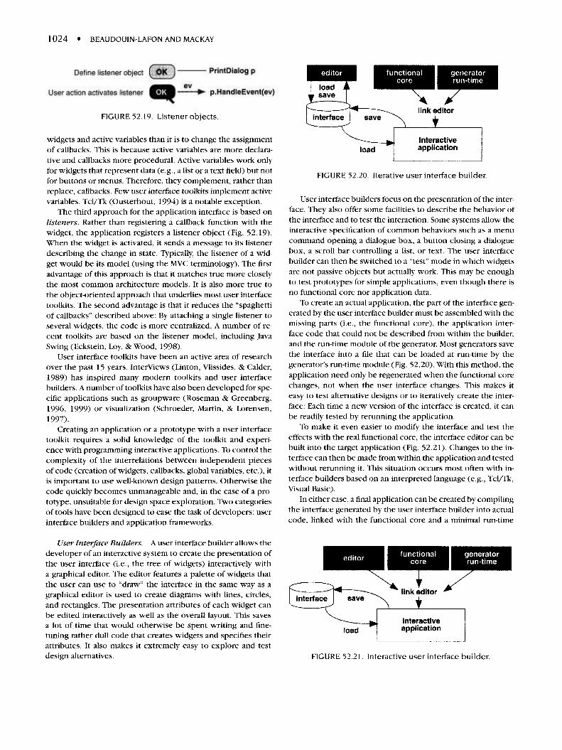
1024 • BEAUDOUIN-LAFON AND MACKAY
FIGURE 52.19. Listener objects.
widgets and active variables than it is to change the assignmentof callbacks. This is because active variables are more declara-tive and callbacks more procedural. Active variables work onlyfor widgets that represent data (e.g., a list or a text field) but notfor buttons or menus. Therefore, they complement, rather thanreplace, callbacks. Few user interface toolkits implement activevariables. Tcl/Tk (Ousterhout, 1994) is a notable exception.
The third approach for the application interface is based onlisteners. Rather than registering a callback function with thewidget, the application registers a listener object (Fig. 52.19).When the widget is activated, it sends a message to its listenerdescribing the change in state. Typically, the listener of a wid-get would be its model (using the MVC terminology). The firstadvantage of this approach is that it matches true more closelythe most common architecture models. It is also more true tothe object-oriented approach that underlies most user interfacetoolkits. The second advantage is that it reduces the "spaghettiof callbacks" described above: By attaching a single listener toseveral widgets, the code is more centralized. A number of re-cent toolkits are based on the listener model, including JavaSwing (Eckstein, Loy, & Wood, 1998).
User interface toolkits have been an active area of researchover the past 15 years. Interviews (Linton, Vlissides, & Calder,1989) has inspired many modern toolkits and user interfacebuilders. A number of toolkits have also been developed for spe-cific applications such as groupware (Roseman & Greenberg,1996, 1999) or visualization (Schroeder, Martin, & Lorensen,1997).
Creating an application or a prototype with a user interfacetoolkit requires a solid knowledge of the toolkit and experi-ence with programming interactive applications. To control thecomplexity of the interrelations between independent piecesof code (creation of widgets, callbacks, global variables, etc.), itis important to use well-known design patterns. Otherwise thecode quickly becomes unmanageable and, in the case of a pro-totype, unsuitable for design space exploration. Two categoriesof tools have been designed to ease the task of developers: userinterface builders and application frameworks.
User Interface Builders. A user interface builder allows thedeveloper of an interactive system to create the presentation ofthe user interface (i.e., the tree of widgets) interactively witha graphical editor. The editor features a palette of widgets thatthe user can use to "draw" the interface in the same way as agraphical editor is used to create diagrams with lines, circles,and rectangles. The presentation attributes of each widget canbe edited interactively as well as the overall layout. This savesa lot of time that would otherwise be spent writing and fine-tuning rather dull code that creates widgets and specifies theirattributes. It also makes it extremely easy to explore and testdesign alternatives.
FIGURE 52.20. Iterative user interface builder.
User interface builders focus on the presentation of the inter-face. They also offer some facilities to describe the behavior ofthe interface and to test the interaction. Some systems allow theinteractive specification of common behaviors such as a menucommand opening a dialogue box, a button closing a dialoguebox, a scroll bar controlling a list, or text. The user interfacebuilder can then be switched to a "test" mode in which widgetsare not passive objects but actually work. This may be enoughto test prototypes for simple applications, even though there isno functional core nor application data.
To create an actual application, the part of the interface gen-erated by the user interface builder must be assembled with themissing parts (i.e., the functional core), the application inter-face code that could not be described from within the builder,and the run-time module of the generator. Most generators savethe interface into a file that can be loaded at run-time by thegenerator's run-time module (Fig. 52.20). With this method, theapplication need only be regenerated when the functional corechanges, not when the user interface changes. This makes iteasy to test alternative designs or to iteratively create the inter-face: Each time a new version of the interface is created, it canbe readily tested by rerunning the application.
To make it even easier to modify the interface and test theeffects with the real functional core, the interface editor can bebuilt into the target application (Fig. 52.21). Changes to the in-terface can then be made from within the application and testedwithout rerunning it. This situation occurs most often with in-terface builders based on an interpreted language (e.g., Tcl/Tk,Visual Basic).
In either case, a final application can be created by compilingthe interface generated by the user interface builder into actualcode, linked with the functional core and a minimal run-time
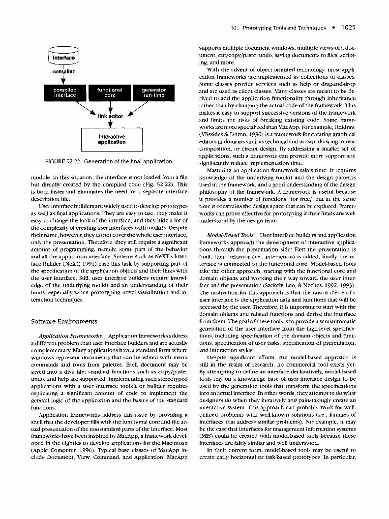
52. Prototyping Tools and Techniques • 1025
FIGURE 52.22. Generation of the final application.
module. In this situation, the interface is not loaded from a filebut directly created by the compiled code (Fig. 52.22). Thisis both faster and eliminates the need for a separate interfacedescription file.
User interface builders are widely used to develop prototypesas well as final applications. They are easy to use, they make iteasy to change the look of the interface, and they hide a lot ofthe complexity of creating user interfaces with toolkits. Despitetheir name, however, they do not cover the whole user interface,only the presentation. Therefore, they still require a significantamount of programming, namely, some part of the behaviorand all the application interface. Systems such as NeXT's Inter-face Builder (NeXT, 1991) ease this task by supporting part ofthe specification of the application objects and their links withthe user interface. Still, user interface builders require knowl-edge of the underlying toolkit and an understanding of theirlimits, especially when prototyping novel visualization and in-teraction techniques.
Software Environments
Application Frameworks. Application frameworks addressa different problem than user interface builders and are actuallycomplementary. Many applications have a standard form wherewindows represent documents that can be edited with menucommands and tools from palettes. Each document may besaved into a disk file; standard functions such as copy/paste,undo, and help are supported. Implementing such stereotypedapplications with a user interface toolkit or builder requiresreplicating a significant amount of code to implement thegeneral logic of the application and the basics of the standardfunctions.
Application frameworks address this issue by providing ashell that the developer fills with the functional core and the ac-tual presentation of the nonstandard parts of the interface. Mostframeworks have been inspired by MacApp, a framework devel-oped in the eighties to develop applications for the Macintosh(Apple Computer, 1996). Typical base classes of MacApp in-clude Document, View, Command, and Application. MacApp
supports multiple document windows, multiple views of a doc-ument, cut/copy/paste, undo, saving documents to files, script-ing, and more.
With the advent of object-oriented technology, most appli-cation frameworks are implemented as collections of classes.Some classes provide services such as help or drag-and-dropand are used as client classes. Many classes are meant to be de-rived to add the application functionality through inheritancerather than by changing the actual code of the framework. Thismakes it easy to support successive versions of the frameworkand limits the risks of breaking existing code. Some frame-works are more specialized than MacApp. For example, Unidraw(Vlissides & Linton, 1990) is a framework for creating graphicaleditors in domains such as technical and artistic drawing, musiccomposition, or circuit design. By addressing a smaller set ofapplications, such a framework can provide more support andsignificantly reduce implementation time.
Mastering an application framework takes time. It requiresknowledge of the underlying toolkit and the design patternsused in the framework, and a good understanding of the designphilosophy of the framework. A framework is useful becauseit provides a number of functions "for free," but at the sametime it constrains the design space that can be explored. Frame-works can prove effective for prototyping if their limits are wellunderstood by the design team.
Model-Based Tools. User interface builders and applicationframeworks approach the development of interactive applica-tions through the presentation side: First the presentation isbuilt, then behavior (i.e., interaction) is added; finally the in-terface is connected to the functional core. Model-based toolstake the other approach, starting with the functional core anddomain objects and working their way toward the user inter-face and the presentation (Szekely, Luo, & Neches, 1992,1993).The motivation for this approach is that the raison d'etre of auser interface is the application data and functions that will beaccessed by the user. Therefore, it is important to start with thedomain objects and related functions and derive the interfacefrom them. The goal of these tools is to provide a semiautomaticgeneration of the user interface from the high-level specifica-tions, including specification of the domain objects and func-tions, specification of user tasks, specification of presentation,and interaction styles.
Despite significant efforts, the model-based approach isstill in the realm of research; no commercial tool exists yet.By attempting to define an interface declaratively, model-basedtools rely on a knowledge base of user interface design to beused by the generation tools that transform the specificationsinto an actual interface. In other words, they attempt to do whatdesigners do when they iteratively and painstakingly create aninteractive system. This approach can probably work for well-defined problems with well-known solutions (i.e., families ofinterfaces that address similar problems). For example, it maybe the case that interfaces for management information systems(MIS) could be created with model-based tools because theseinterfaces are fairly similar and well understood.
In their current form, model-based tools may be useful tocreate early horizontal or task-based prototypes. In particular,
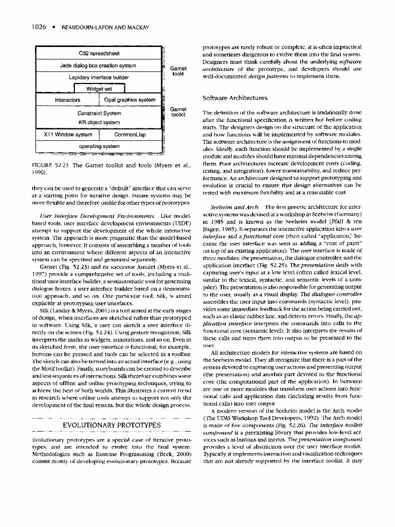
1026 • BEAUDOUIN-LAFON AND MACKAY
FIGURE 52.23. The Garnet toolkit and tools (Myers et al.,1990).
they can be used to generate a "default" interface that can serveas a starting point for iterative design. Future systems may bemore flexible and therefore usable for other types of prototypes.
User Interface Development Environments. Like model-based tools, user interface development environments (UIDE)attempt to support the development of the whole interactivesystem. The approach is more pragmatic than the model-basedapproach, however. It consists of assembling a number of toolsinto an environment where different aspects of an interactivesystem can be specified and generated separately.
Garnet (Fig. 52.23) and its successor Amulet (Myers et al.,1997) provide a comprehensive set of tools, including a tradi-tional user interface builder, a semiautomatic tool for generatingdialogue boxes, a user interface builder based on a demonstra-tion approach, and so on. One particular tool, Silk, is aimedexplicitly at prototyping user interfaces.
Silk (Landay & Myers, 2001) is a tool aimed at the early stagesof design, when interfaces are sketched rather than prototypedin software. Using Silk, a user can sketch a user interface di-rectly on the screen (Fig. 52.24). Using gesture recognition, Silkinterprets the marks as widgets, annotations, and so on. Even inits sketched form, the user interface is functional; for example,buttons can be pressed and tools can be selected in a toolbar.The sketch can also be turned into an actual interface (e.g., usingthe Motif toolkit). Finally, storyboards can be created to describeand test sequences of interactions. Silk therefore combines someaspects of offline and online prototyping techniques, trying toachieve the best of both worlds. This illustrates a current trendin research where online tools attempt to support not only thedevelopment of the final system, but the whole design process.
EVOLUTIONARY PROTOTYPES
Evolutionary prototypes are a special case of iterative proto-types, and are intended to evolve into the final system.Methodologies such as Extreme Programming (Beck, 2000)consist mostly of developing evolutionary prototypes. Because
prototypes are rarely robust or complete, it is often impracticaland sometimes dangerous to evolve them into the final system.Designers must think carefully about the underlying softwarearchitecture of the prototype, and developers should usewell-documented design patterns to implement them.
Software Architectures
The definition of the software architecture is traditionally doneafter the functional specification is written but before codingstarts. The designers design on the structure of the applicationand how functions will be implemented by software modules.The software architecture is the assignment of functions to mod-ules. Ideally, each function should be implemented by a singlemodule and modules should have minimal dependencies amongthem. Poor architectures increase development costs (coding,testing, and integration), lower maintainability, and reduce per-formance. An architecture designed to support prototyping andevolution is crucial to ensure that design alternatives can betested with maximum flexibility and at a reasonable cost.
Seeheim and Arch. The first generic architecture for inter-active systems was devised at a workshop in Seeheim (Germany)in 1985 and is known as the Seeheim model (Pfaff & tenHagen, 1985). It separates the interactive application into a userinterface and a functional core (then called "application," be-cause the user interface was seen as adding a "coat of paint"on top of an existing application). The user interface is made ofthree modules: the presentation, the dialogue controller, and theapplication interface (Fig. 52.25). The presentation deals withcapturing user's input at a low level (often called lexical level,similar to the lexical, syntactic, and semantic levels of a com-piler). The presentation is also responsible for generating outputto the user, usually as a visual display. The dialogue controllerassembles the user input into commands (syntactic level), pro-vides some immediate feedback for the action being carried out,such as an elastic rubber line, and detects errors. Finally, the ap-plication interface interprets the commands into calls to thefunctional core (semantic level). It also interprets the results ofthese calls and turns them into output to be presented to theuser.
All architecture models for interactive systems are based onthe Seeheim model. They all recognize that there is a part of thesystem devoted to capturing user actions and presenting output(the presentation) and another part devoted to the functionalcore (the computational part of the application). In betweenare one or more modules that transform user actions into func-tional calls and application data (including results from func-tional calls) into user output.
A modern version of the Seeheim model is the Arch model(The UIMS Workshop Tool Developers, 1992). The Arch modelis made of five components (Fig. 52.26). The interface toolkitcomponent is a preexisting library that provides low-level ser-vices such as buttons and menus. The presentation componentprovides a level of abstraction over the user interface toolkit.Typically, it implements interaction and visualization techniquesthat are not already supported by the interface toolkit. It may
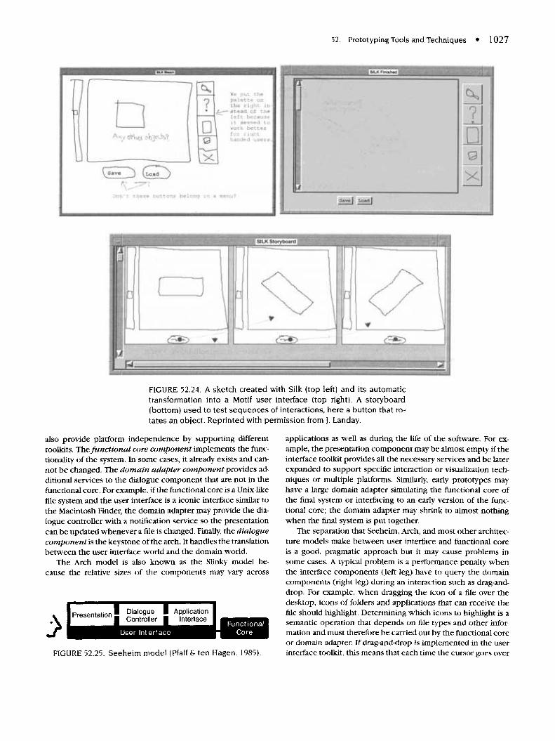
52. Prototyping Tools and Techniques • 1027
FIGURE 52.24. A sketch created with Silk (top left) and its automatictransformation into a Motif user interface (top right). A storyboard(bottom) used to test sequences of interactions, here a button that ro-tates an object. Reprinted with permission from J. Landay.
also provide platform independence by supporting differenttoolkits. The functional core component implements the func-tionality of the system. In some cases, it already exists and can-not be changed. The domain adapter component provides ad-ditional services to the dialogue component that are not in thefunctional core. For example, if the functional core is a Unix-likefile system and the user interface is a iconic interface similar tothe Macintosh Finder, the domain adapter may provide the dia-logue controller with a notification service so the presentationcan be updated whenever a file is changed. Finally, the dialoguecomponent is the keystone of the arch. It handles the translationbetween the user interface world and the domain world.
The Arch model is also known as the Slinky model be-cause the relative sizes of the components may vary across
FIGURE 52.25. Seeheim model (Pfaff & ten Hagen, 1985).
applications as well as during the life of the software. For ex-ample, the presentation component may be almost empty if theinterface toolkit provides all the necessary services and be laterexpanded to support specific interaction or visualization tech-niques or multiple platforms. Similarly, early prototypes mayhave a large domain adapter simulating the functional core ofthe final system or interfacing to an early version of the func-tional core; the domain adapter may shrink to almost nothingwhen the final system is put together.
The separation that Seeheim, Arch, and most other architec-ture models make between user interface and functional coreis a good, pragmatic approach but it may cause problems insome cases. A typical problem is a performance penalty whenthe interface components (left leg) have to query the domaincomponents (right leg) during an interaction such as drag-and-drop. For example, when dragging the icon of a file over thedesktop, icons of folders and applications that can receive thefile should highlight. Determining which icons to highlight is asemantic operation that depends on file types and other infor-mation and must therefore be carried out by the functional coreor domain adapter. If drag-and-drop is implemented in the userinterface toolkit, this means that each time the cursor goes over
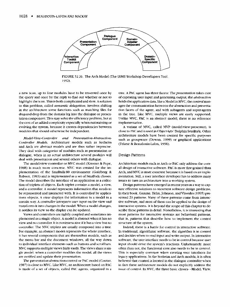
1028 • BEAUDOUIN-LAFON AND MACKAY
FIGURE 52.26. The Arch Model (The UIMS Workshop Developers Tool,1992).
a new icon, up to four modules have to be traversed once bythe query and once by the reply to find out whether or not tohighlight the icon. This is both complicated and slow. A solutionto this problem, called semantic delegation, involves shiftingin the architecture some functions such as matching files fordrag-and-drop from the domain leg into the dialogue or presen-tation component. This may solve the efficiency problem, but atthe cost of an added complexity especially when maintaining orevolving the system, because it creates dependencies betweenmodules that should otherwise be independent.
Model-View-Controller and Presentation-Abstraction-Controller Models. Architecture models such as Seeheimand Arch are abstract models and are thus rather imprecise.They deal with categories of modules such as presentation ordialogue, when in an actual architecture several modules willdeal with presentation and several others with dialogue.
The model-view-controller or MVC model (Krasner & Pope,1988) is much more concrete. MVC was created for the im-plementation of the Smalltalk-80 environment (Goldberg &Robson, 1983) and is implemented as a set of Smalltalk classes.The model describes the interface of an application as a collec-tion of triplets of objects. Each triplet contains a model, a view,and a controller. A model represents information that needs tobe represented and interacted with. It is controlled by applica-tions objects. A view displays the information in a model in acertain way. A controller interprets user input on the view andtransforms it into changes in the model. When a model changes,it notifies its view so the display can be updated.
Views and controllers are tightly coupled and sometimes im-plemented as a single object. A model is abstract when it has noview and no controller. It is noninteractive if it has a view but nocontroller. The MVC triplets are usually composed into a tree.For example, an abstract model represents the whole interface,it has several components that are themselves models, such asthe menu bar and the document windows, all the way downto individual interface elements such as buttons and scrollbars.MVC supports multiple views fairly easily. The views share a sin-gle model; when a controller modifies the model, all the viewsare notified and update their presentation.
The presentation-abstraction-control or PAC model (Coutaz,1987) is close to MVC. Like MVC, an architecture based on PACis made of a set of objects, called PAC agents, organized in a
tree. A PAC agent has three facets: The presentation takes careof capturing user input and generating output; the abstractionholds the application data, like a Model in MVC; the control man-ages the communication between the abstraction and presenta-tion facets of the agent, and with subagents and super-agentsin the tree. Like MVC, multiple views are easily supported.Unlike MVC, PAC is an abstract model; there is no referenceimplementation.
A variant of MVC, called MVP (model-view-presenter), isclose to PAC and is used in ObjectArts' Dolphin Smalltalk. Otherarchitecture models have been created for specific purposessuch as groupware (Dewan, 1999) or graphical applications(Fekete & Beaudouin-Lafon, 1996).
Design Patterns
Architecture models such as Arch or PAC only address the over-all design of interactive software. PAC is more fine-grained thanArch, and MVC is more concrete because it is based on an imple-mentation. Still, a user interface developer has to address manyissues to turn an architecture into a working system.
Design patterns have emerged in recent years as a way to cap-ture effective solutions to recurrent software design problems.In their book, Gamma, Helm, Johnson, and Vlissides (1995) pre-sented 23 patterns. Many of these patterns come from interac-tive software, and most of them can be applied to the design ofinteractive systems. It is beyond the scope of this chapter to de-scribe these patterns in detail. Nonetheless, it is interesting thatmost patterns for interactive systems are behavioral patterns,that is, patterns that describe how to implement the controlstructure of the system.
Indeed, there is a battle for control in interactive software.In traditional, algorithmic software, the algorithm is in controland decides when to read input and write output. In interactivesoftware, the user interface needs to be in control because userinput should drive the system's reactions. Unfortunately, moreoften than not, the functional core also needs to be in control.This is especially common when creating user interfaces forlegacy applications. In the Seeheim and Arch models, it is oftenbelieved that control is located in the dialogue controller whenin fact these architecture models do not explicitly address theissue of control. In MVC, the three basic classes—Model, View,
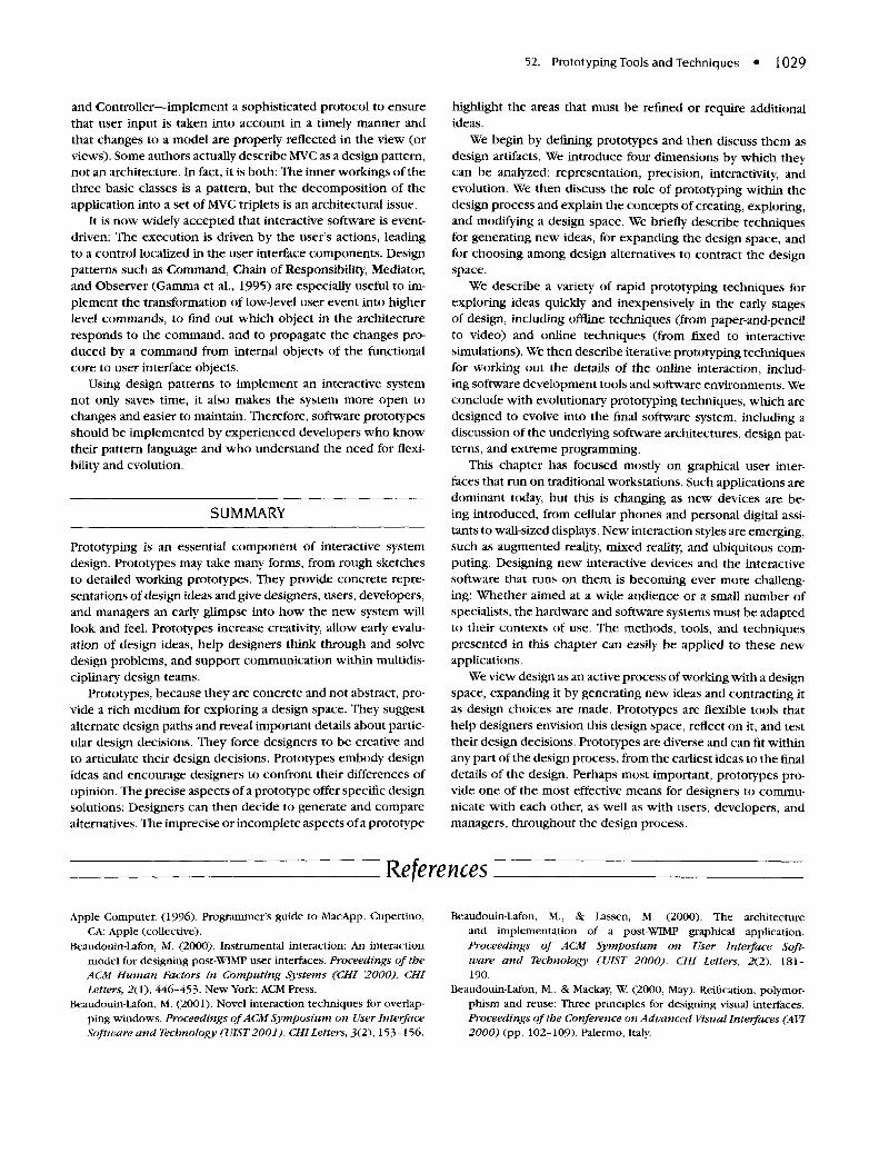
52. Prototyping Tools and Techniques • 1029
and Controller—implement a sophisticated protocol to ensurethat user input is taken into account in a timely manner andthat changes to a model are properly reflected in the view (orviews). Some authors actually describe MVC as a design pattern,not an architecture. In fact, it is both: The inner workings of thethree basic classes is a pattern, but the decomposition of theapplication into a set of MVC triplets is an architectural issue.
It is now widely accepted that interactive software is event-driven: The execution is driven by the user's actions, leadingto a control localized in the user interface components. Designpatterns such as Command, Chain of Responsibility, Mediator,and Observer (Gamma et al., 1995) are especially useful to im-plement the transformation of low-level user event into higherlevel commands, to find out which object in the architectureresponds to the command, and to propagate the changes pro-duced by a command from internal objects of the functionalcore to user interface objects.
Using design patterns to implement an interactive systemnot only saves time, it also makes the system more open tochanges and easier to maintain. Therefore, software prototypesshould be implemented by experienced developers who knowtheir pattern language and who understand the need for flexi-bility and evolution.
SUMMARY
Prototyping is an essential component of interactive systemdesign. Prototypes may take many forms, from rough sketchesto detailed working prototypes. They provide concrete repre-sentations of design ideas and give designers, users, developers,and managers an early glimpse into how the new system willlook and feel. Prototypes increase creativity, allow early evalu-ation of design ideas, help designers think through and solvedesign problems, and support communication within multidis-ciplinary design teams.
Prototypes, because they are concrete and not abstract, pro-vide a rich medium for exploring a design space. They suggestalternate design paths and reveal important details about partic-ular design decisions. They force designers to be creative andto articulate their design decisions. Prototypes embody designideas and encourage designers to confront their differences ofopinion. The precise aspects of a prototype offer specific designsolutions: Designers can then decide to generate and comparealternatives. The imprecise or incomplete aspects of a prototype
highlight the areas that must be refined or require additionalideas.
We begin by denning prototypes and then discuss them asdesign artifacts. We introduce four dimensions by which theycan be analyzed: representation, precision, interactivity, andevolution. We then discuss the role of prototyping within thedesign process and explain the concepts of creating, exploring,and modifying a design space. We briefly describe techniquesfor generating new ideas, for expanding the design space, andfor choosing among design alternatives to contract the designspace.
We describe a variety of rapid prototyping techniques forexploring ideas quickly and inexpensively in the early stagesof design, including offline techniques (from paper-and-pencilto video) and online techniques (from fixed to interactivesimulations). We then describe iterative prototyping techniquesfor working out the details of the online interaction, includ-ing software development tools and software environments. Weconclude with evolutionary prototyping techniques, which aredesigned to evolve into the final software system, including adiscussion of the underlying software architectures, design pat-terns, and extreme programming.
This chapter has focused mostly on graphical user inter-faces that run on traditional workstations. Such applications aredominant today, but this is changing as new devices are be-ing introduced, from cellular phones and personal digital assi-tants to wall-sized displays. New interaction styles are emerging,such as augmented reality, mixed reality, and ubiquitous com-puting. Designing new interactive devices and the interactivesoftware that runs on them is becoming ever more challeng-ing: Whether aimed at a wide audience or a small number ofspecialists, the hardware and software systems must be adaptedto their contexts of use. The methods, tools, and techniquespresented in this chapter can easily be applied to these newapplications.
We view design as an active process of working with a designspace, expanding it by generating new ideas and contracting itas design choices are made. Prototypes are flexible tools thathelp designers envision this design space, reflect on it, and testtheir design decisions. Prototypes are diverse and can fit withinany part of the design process, from the earliest ideas to the finaldetails of the design. Perhaps most important, prototypes pro-vide one of the most effective means for designers to commu-nicate with each other, as well as with users, developers, andmanagers, throughout the design process.
References
Apple Computer. (1996). Programmer's guide to MacApp. Cupertino,CA: Apple (collective).
Beaudouin-Lafon, M. (2000). Instrumental interaction: An interactionmodel for designing post-WIMP user interfaces. Proceedings of theACM Human Factors in Computing Systems (CHI '2000), CHILetters, 2(1), 446-453. New York: ACM Press.
Beaudouin-Lafon, M. (2001). Novel interaction techniques for overlap-ping windows. Proceedings of ACM Symposium on User InterfaceSoftware and Technology (UIST 2001). CHI Letters, 3(2), 153-156.
Beaudouin-Lafon, M., & Lassen, M. (2000). The architectureand implementation of a post-WIMP graphical application.Proceedings of ACM Symposium on User Interface Soft-ware and Technology (UIST 2000). CHI Letters, 2(2), 181-190.
Beaudouin-Lafon, M., & Mackay, W. (2000, May). Reification, polymor-phism and reuse: Three principles for designing visual interfaces.Proceedings of the Conference on Advanced Visual Interfaces (AVI2000) (pp. 102-109). Palermo, Italy.
1030 • BEAUDOUIN-LAFON AND MACKAY
Beck, K. (2000). Extreme programming explained. New York: Addison-Wesley.
Bederson, B., & Hollan, J. (1994). Pad++: A zooming graphical inter-face for exploring alternate interface physics. Proceedings of ACMSymposium on User Interface Software and Technology (UIST '94)(pp. 17-26). New York: ACM Press.
Bederson, B., & Meyer, J. (1998). Implementing a zooming interface:Experience Building Pad++. Software Practice and Experience,28(10), 1101-1135.
Bederson, B. B., Meyer, J., & Good, L. (2000). Jazz: An extensiblezoomable user interface graphics toolkit in Java. Proceedings of ACMSymposium on User Interface Software and Technology (UIST2000). CHI Letters, 2(2), 171-180.
Bier, E., Stone, M., Pier, K., Buxton, W., & De Rose, T. (1993). Tool-glass and magic lenses: The see-through interface. Proceedings ACMSIGGRAPH '93 (pp. 73-80). New York: ACM Press.
Boehm, B. (1988). A spiral model of software development and enhance-ment. IEEE Computer, 2/(5), 61-72.
B0dker, S., Christiansen, E., & Thuring, M. (1995). A conceptual tool-box for designing CSCW applications. Proceedings of the Interna-tional Workshop on the Design of Cooperative Systems (COOP '95)(pp. 266-284).
B0dker, S., Ehn, P., Knudsen, J., Kyng, M., & Madsen, K. (1988).Computer support for cooperative design. In Proceedings of theCSCW'88 ACM Conference on Computer-Supported CooperativeWork (pp. 377-393). Portland, OR: ACM Press.
Chapanis, A. (1982). Man/computer research at Johns Hopkins. In R. A.Kasschau, R. Lachman, & K. R. Laughery (Eds.), Information Tech-nology and Psychology: Prospects for the Future (pp. 238-249).New York: Praeger.
Collaros, P. A., & Anderson, L. R. (1969). Effect of perceived expert-ness upon creativity of members of brainstorming groups. Journalof Applied Psychology, 53, 159-163.
Coutaz, J. (1987). PAC, an object oriented model for dialog design. InH.J. Bullinger & B. Shackel (Eds.), Proceedings of INTERACT '87(pp. 431-436). Amsterdam: Elsevier Science.
de Vreede, G.-J., Briggs, R. O., van Duin, R., & Enserink, B. (2000).Athletics in electronic brainstorming: Asynchronous brainstormingin very large groups. Proceedings of HICSS-33.
Dewan, P (1999). Architectures for collaborative applications. InM. Beaudouin-Lafon (Ed.), Computer-supported co-operative work(Trends in Software Series, pp. 169-193). New York: JohnWiley.
Diehl, M., & Strobe, W. (1987). Productivity loss in brainstorminggroups: Toward the solution of a riddle. Journal of Personality andSocial Psychology, 53, 497-509.
Dykstra-Erickson, E., Mackay, W. E., & Arnowitz, J. (2001, March).Trialogue on Design (of). ACM/Interactions, 8(2), 109-117.
Dourish, P. (1997). Accounting for system behaviour: Representation,reflection and resourceful action. In M. Kyng & L. Mathiassen (Eds.),Computers and design in context (pp. 145-170). Cambridge, MA:MIT Press.
Eckstein, R., Loy M., & Wood, D. (1998). Java Swing. Cambridge, MA:O'Reilly.
Fekete, J.-D., & Beaudouin-Lafon, M. (1996). Using the multi-layer modelfor building interactive graphical applications. In Proceedings ofACM Symposium on User Interface Software and Technology (UIST'96) (pp. 109-118). New York: ACM Press.
Gamma, E., Helm, R., Johnson, R., & Vlissides, J. (1995). Designpatterns, elements of reusable object-oriented software. Reading,MA: Addison Wesley.
Goldberg, A., & Robson, D. (1983). Smalltalk—80: The language andits implementation. Reading, MA: Addison Wesley.
Goodman, D. (1987). The complete HyperCard handbook. New York:Bantam Books.
Good, M., Whiteside, J., Wixon, D., & Jones, S. (1984, October). Buildinga user-derived interface. Communications of the ACM, 27(10),1032-1043.
Greenbaum, J., & Kyng, M. (Eds.). (1991). Design at work: Coopera-tive design of computer systems. Hillsdale, NJ: Lawrence ErlbaumAssociates.
Houde, S., & Hill, C. (1997). What do prototypes prototype? In Hand-book of human computer interaction (2nd ed. rev, pp. 367-381).Amsterdam: North-Holland.
Kelley, J. F. (1983). An empirical methodology for writing user-friendlynatural language computer applications. In Proceedings of CHI '83Conference on Human Factors in Computing Systems. New York:ACM Press.
Krasner, E. G., & Pope, S. T. (1988, August/September). A cookbookfor using the model-view-controller user interface paradigmin Smalltalk-80. Journal of Object-Oriented Programming,27-49.
Kurtenbach, G., Fitzmaurice, G., Baudel, T, & Buxton, W. (1997). Thedesign of a GUI paradigm based on tablets, two-hands, and trans-parency. Proceedings of ACM Human Factors in Computing Sys-tems (CHI '97) (pp. 35-42). New York: ACM Press.
Landay, J., & Myers, B. A. (2001). Sketching interfaces: Toward morehuman interface design. IEEE Computer, 34, 56-64.
Linton, M. A., Vlissides, J. M., & Calder, P. R. (1989). Composing userinterfaces with Interviews. IEEE Computer, 22, 8-22.
Mackay, W E. (1988). Video prototyping: A technique for developing hy-permedia systems. Demonstration, CHI '88, Conference on HumanFactors in Computing Systems. Retrieved from http://www.lri.fr/-mackay/publications.html
Mackay, W E., & Pagani, D. (1994). Video Mosaic: Laying out time in aphysical space. Proceedings of ACM Multimedia '94 (pp. 165-172).New York: ACM Press.
Mackay, W E., & Fayard, A.-L. (1997). HCI, natural science and design: Aframework for triangulation across disciplines. Proceedings of ACMDIS '97, Designing Interactive Systems (pp. 223-234). New York:ACM Press.
Mackay, W, Fayard, A.-L., Frobert, L., & Medini, L. (1998). Reinventingthe familiar: Exploring an augmented reality design space for airtraffic control. Proceedings of ACM Conference on Human Factorsin Computing Systems (CHI '98) (pp. 558-565). New York: ACMPress.
Mackay, W. E. (2000). Video techniques for participatory design:Observation, brainstorming & prototyping. Tutorial Notes, CHI2000, Human Factors in Computing Systems. Retrieved fromhttp://www.lri.fr/~mackay/publications.html
Mackay, W, Ratzer, A., & Janecek, P. (2000). Video artifacts for design:Bridging the gap between abstraction and detail. Proceedings ACMConference on Designing Interactive Systems (DIS 2000) (pp. 72-82). New York: ACM Press.
Muller, M. (1991). PICTIVE: An exploration in participatory de-sign. Proceedings of ACM Conference on Human Factors inComputing Systems (CHI '91) (pp. 225-231). New York: ACMPress.
Myers, B. A., Giuse, D. A., Dannenberg, R. B., Vander Zander, B., Kosbie,D. S., Pervin, E., Mickish, A., & Marchal, P. (1990). Garnet: Com-prehensive support for graphical, highly-interactive user interfaces.IEEE Computer, 23(11), 71-85.
Myers, B. A. (1991). Separating application code from toolkits: Elimi-nating the spaghetti of call-backs. Proceedings of ACM SIGGRAPHSymposium on User Interface Software and Technology (UIST '91)(pp. 211-220). New York: ACM Press.
52. Prototyping Tools and Techniques • 1031
Myers, B. A., & Rosson, M. B. (1992). Survey on user interface pro-gramming. Proceedings of the ACM Conference on Human Factorsin Computing Systems (CHI '92) (pp. 195-202). New York: ACMPress.
Myers, B. A., McDaniel, R. G., Miller, R. C., Ferrency, A. S., Faulring, A.,Kyle, B. D., Mickish, A., Klimotivtski, A., & Doane, P. (1997). TheAmulet environment. IEEE Transactions on Software Engineering,23(6), 347-365.
NeXT Corporation. (1991). NeXT Interface Builder reference manual.Redwood City, CA.
Norman, D. A., & Draper, S. W. (Eds.). (1986). User centered systemdesign. Hillsdale, NJ: Lawrence Erlbaum Associates.
Osborn, A. (1957). Applied imagination: Principles and procedures ofcreative thinking (rev. ed.). New York: Scribner's.
Ousterhout, J. K. (1994). Tcl and the Tk Toolkit. Reading, MA: AddisonWesley.
Perkins, R., Keller, D. S., & Ludolph, F. (1997). Inventing the Lisa UserInterface. ACM Interactions, 4(1), 40-53.
Pfaff, G. P., & ten Hagen, P. J. W. (Eds.). (1985). User interface manage-ment systems. Berlin: Springer.
Raskin, J. (2000). The humane interface. New York: Addison Wesley.Roseman, M., & Greenberg, S. (1996). Building real-time groupware with
GroupKit, a groupware toolkit. ACM Transactions on Computer-Human Interaction, 3(1), 66-106.
Roseman, M., & Greenberg, S. (1999). Groupware toolkits for syn-chronous work. In M. Beaudouin-Lafon (Ed.). Computer-supported
co-operative work (Trends in software series, pp. 135-168). NewYork: John Wiley.
Schroeder, W., Martin, K., & Lorensen, B. (1997). The visualizationtoolkit. New York: Prentice Hall.
Strass, P. (1993). IRIS Inventor, a 3D graphics toolkit. Proceedings ACMConference on Object-Oriented Programming, Systems, Languagesand Applications (OOPSLA '93) (pp. 192-200). New York: ACMPress.
Szekely, P., Luo, P., & Neches, R. (1992). Facilitating the exploration ofinterface design alternatives: The HUMANOID. Proceedings of ACMConference on Human Factors in Computing Systems (CHI '92)(pp. 507-515). New York: ACM Press.
Szekely, P., Luo, P., & Neches, R. (1993). Beyond interface builders:Model-based interface tools. Proceedings of ACM/IFIP Confer-ence on Human Factors in Computing Systems (INTERCHI '93)(pp. 383-390). New York: ACM Press.
The UIMS Workshop Tool Developers. (1992). A metamodel for the run-time architecture of an interactive system. SIGCHI Bulletin, 24(1),32-37.
Vlissides, J. M., & Linton, M. A. (1990). Unidraw: A framework for build-ing domain-specific graphical editors. ACM Transactions on Infor-mation Systems, 8(3), 237-268.
Wegner, P. (1997). Why interaction is more powerful than algorithms.Communications of the ACM, 40(5), 80-91.
Woo, M., Neider, J., & Davis, T. (1997). OpenGL programming guide.Reading, MA: Addison-Wesley.


![Extension and analysis of hybrid ARQ schemes in the context ......Other [cond-mat.other]. Université Paris Sud - Paris XI, 2014. English. NNT: 2014PA112105 . tel-01058051 UNIVERSITE](https://static.fdocuments.net/doc/165x107/6105d5e16184a37b5517f6d3/extension-and-analysis-of-hybrid-arq-schemes-in-the-context-other-cond-matother.jpg)


![Codage de sources avec information adjacente et ......Autre [cond-mat.other]. Université Paris Sud - Paris XI, 2013. Français. NNT: 2013PA112301 . tel-01136663v2 UNIVERSITE PARIS-SUD](https://static.fdocuments.net/doc/165x107/610014643d759a65fc329e05/codage-de-sources-avec-information-adjacente-et-autre-cond-matother.jpg)
