Universal Crane Model for the Ship Design System E4...model for the ship design process, In order to...
9
1 Copyright © 2014 by ASME Proceedings of the ASME 2014 33rd International Conference on Ocean, Offshore and Arctic Engineering OMAE2014 June 8-13, 2014, San Francisco, California, USA OMAE2014-23499 UNIVERSAL CRANE MODEL FOR THE SHIP DESIGN SYSTEM E4 Hendrik Vorhölter * Mareval AG Hamburg, Germany Email: [email protected] Jakob Christiansen HeavyLift@Sea GmbH Hamburg, Germany Email: [email protected] Hannes Hatecke Hamburg University of Technology (TUHH) Hamburg, Germany Email: [email protected] * Address all correspondence to this author ABSTRACT For the ship design system E4 a universal crane model was developed. With the help of this model the design of crane vessels and cranes can be harmonised better and lifting operations can be analysed more precisely. The model is able to handle any type of cranes which are used in the shipping and offshore industry and provides the input for every simulations method within E4 which needs to consider crane operations. Special focus was given on keeping a common user interface both for the designer of a crane vessel and the planning engineer for lifting operations independently of the type and functionalities of the crane. Such a universal crane model has not been implemented in any other ship design software until now. In this article the motivation for the development of the model is described together with the requirements for a universal crane model. The principle of the model explained and its functionality is demonstrated in several examples. Keywords: Ship Design, Software, Offshore, Lifting, Crane INTRODUCTION In recent years more and more heavy lifting crane operations in the offshore industry have been performed by floating vessels. On the one hand, the oil and gas industry is exploring deeper water depth where the use of jack-up or fixed platforms is not feasible any more. On the other hand, the offshore wind industry requires cost efficient solutions for heavy lifting operations. In order to increase the usability and the operational range of floating crane vessels new ship designs have to be developed and the reliability of the prediction of the operational capability for lifting operations has to be increased. In most cases the crane and the vessel on which it is installed are designed independently from each other. This is for several reasons: Very often the crane and the vessel are designed from independent companies or the crane shall be suitable for the installation on different ship types and vice versa. Hence, the crane is very often incorporated into the ship design process only by its required space, weight and a load chart. But if the operational capability of a crane vessel in offshore lifting operations shall be driven to its maximum, ship and crane have to harmonised in their dynamic behaviour. This requires an integrated crane model for the ship design process, which most ship design systems do not have. In order to overcome this problem a universal crane model was developed as part of the joint research and development project “HoOK” for the ship design system E4 [2]. The aim of the HoOK project is to provide an integrated simulation tool for lifting operations with ships for the early ship design as well as the planning of lifting operations offshore and inshore (see also [3]). The aims of the HoOK project are described below. This is followed by a description of the ship design system E4 and its underlaying philosophy. After defining the requirements for a universal crane model the implemented crane model is described. The article concludes with some application examples and an outlook on future work.
Transcript of Universal Crane Model for the Ship Design System E4...model for the ship design process, In order to...

1 Copyright © 2014 by ASME
Proceedings of the ASME 2014 33rd International Conference on Ocean, Offshore and Arctic Engineering
OMAE2014
June 8-13, 2014, San Francisco, California, USA
OMAE2014-23499
UNIVERSAL CRANE MODEL FOR THE SHIP DESIGN SYSTEM E4
Hendrik Vorhölter*
Mareval AG Hamburg, Germany
Email: [email protected]
Jakob Christiansen HeavyLift@Sea GmbH
Hamburg, Germany Email: [email protected]
Hannes Hatecke Hamburg University of Technology (TUHH)
Hamburg, Germany Email: [email protected]
* Address all correspondence to this author
ABSTRACT For the ship design system E4 a universal crane model was
developed. With the help of this model the design of crane
vessels and cranes can be harmonised better and lifting
operations can be analysed more precisely. The model is able to
handle any type of cranes which are used in the shipping and
offshore industry and provides the input for every simulations
method within E4 which needs to consider crane operations.
Special focus was given on keeping a common user interface
both for the designer of a crane vessel and the planning
engineer for lifting operations independently of the type and
functionalities of the crane. Such a universal crane model has
not been implemented in any other ship design software until
now.
In this article the motivation for the development of the
model is described together with the requirements for a
universal crane model. The principle of the model explained
and its functionality is demonstrated in several examples.
Keywords: Ship Design, Software, Offshore, Lifting, Crane
INTRODUCTION In recent years more and more heavy lifting crane
operations in the offshore industry have been performed by
floating vessels. On the one hand, the oil and gas industry is
exploring deeper water depth where the use of jack-up or fixed
platforms is not feasible any more. On the other hand, the
offshore wind industry requires cost efficient solutions for
heavy lifting operations. In order to increase the usability and
the operational range of floating crane vessels new ship designs
have to be developed and the reliability of the prediction of the
operational capability for lifting operations has to be increased.
In most cases the crane and the vessel on which it is
installed are designed independently from each other. This is for
several reasons: Very often the crane and the vessel are
designed from independent companies or the crane shall be
suitable for the installation on different ship types and vice
versa. Hence, the crane is very often incorporated into the ship
design process only by its required space, weight and a load
chart. But if the operational capability of a crane vessel in
offshore lifting operations shall be driven to its maximum, ship
and crane have to harmonised in their dynamic behaviour. This
requires an integrated crane model for the ship design process,
which most ship design systems do not have.
In order to overcome this problem a universal crane model
was developed as part of the joint research and development
project “HoOK” for the ship design system E4 [2]. The aim of
the HoOK project is to provide an integrated simulation tool for
lifting operations with ships for the early ship design as well as
the planning of lifting operations offshore and inshore (see also
[3]). The aims of the HoOK project are described below. This is
followed by a description of the ship design system E4 and its
underlaying philosophy. After defining the requirements for a
universal crane model the implemented crane model is
described. The article concludes with some application
examples and an outlook on future work.

2 Copyright © 2014 by ASME
FIGURE 1. PLATFORM LIFTING WITH FLOATING SHEER LEG MATADOR 3
FIGURE 2: INSTALLATION OF A TIDAL TURBINE WITH A CONVENTIONAL HEAVY LIFT CARRIER SIETAS TYPE 183 (COPYRIGHT SAL HEAVYLIFT GMBH)
R&D PROJECT HOOK There are a large number of different tools for the
simulation of different aspects of transport and installation
operations. But, there is a lack of comprehensive, fast and
reliable simulations tools that are suitable for the early design
and planning phase. In order to fill this gap, the research and
development project “Hochsee-Operationen mit Kranen”
(Offshore operations with cranes) – in short “HoOK” – has
been started in spring 2013 (see also [3] and [7]). It aims at the
development of new simulation tools for offshore lifting
operations. The project consortium consists of the ship design
office HeavyLift@Sea, the Institute of Ship Design and Ship
Safety of the Hamburg University of Technology (TUHH) and
the marine consultancy office MAREVAL as project
coordinator. In this consortium, the different strengths of the
three partners are combined: MAREVAL’s experience in
offshore operations and offshore technology, HeavyLift@Sea’s
experience in the design of heavy lift vessels and the
competence of TUHH in the development of software for
dynamic ship simulations. The project is scheduled for a three
year period and is funded by the German Federal Ministry of
Economics and Technology in its program “Maritime
Technologien der nächsten Generation” (“Next-Generation
Maritime Technologies”).
SHIP DESIGN SYSTEM E4 E4 is a ship design system especially developed for the
early design phase. The early design phase in the ship building
industry is characterized by extremely short lead times for a
rather complex task. Within a few days or weeks all key
elements of the ship and its major systems have to be analysed
with respect to their functionality, weight and space
requirements as well as costs. This can only be achieved by the
coordinated work of experts from various disciplines.
Therefore, the main features of E4 are multi-user functionality,
the use of a common data base for all embedded tools and the
use of first principal based direct simulation methods already
for the early design. The design of the common data base
follows the philosophy that only the original data is stored. Any
information which can be derived from the original data quickly
is generated only if it is required.
The embedded tools in E4 can address all topics which are
part of the traditional work of a project department or design
office, e.g. hull form development, loading conditions, intact
and damage stability as well as speed power performance. But
manoeuvring, dynamic positioning and sea keeping analysis
both in frequency and in time domain can also be performed
with E4.
Until now no explicit crane model exists for E4. Crane
operations can only be analysed by modifying the light ship
weight distribution and the loading conditions manually. This is
for some hydrostatic analysis sufficient but with low
performance. And for dynamic analysis it is inadequate. The
crane model to be developed shall provide the common data
base for the description of cranes and crane loads for any
analysis tools used in E4. Additionally the crane model shall
comply to the needs of tools to be developed in the future. For
instance, within the HoOK-project a module will be developed
which allows the chronological description of lifting operations
including water ballast operations.
REQUIREMENTS FOR A UNIVERSAL CRANE MODEL The first step for the development of a universal crane
model is to define the requirements for the model. Most of the
requirements are a consequence of the above described
philosophy of E4 and the aspired use of the model. The
requirements identified by the project consortium are as
follows:
The model shall be suitability for the early design
phase which requires simple modelling of the basic
cases like a single hook operation of one crane and the

3 Copyright © 2014 by ASME
possibility for fast modifications of the key parameters
like the load or outreach.
Advanced simulations require more detailed
information about the velocities and limits of the crane
components, which need to be provided.
It must be possible to handle all types of cranes used in
the shipping and offshore industry, like pedestal crane
and A-frames, cylinder and wire luffing cranes,
knuckle-boom and gantry cranes.
The necessary input must be restricted to data, which is
available for the ship designer, i.e. no internal know-
how from the crane manufacturer should be required.
The definition of a crane and crane load with its
functionality and geometry must be quick via a user
interface.
The model must be suitable for modelling and
handling multiple cranes or hooks lifting operations.
Data transfer from one project to another must be
possible like the replacement of the crane information
within one project.
The model must be able to compute the equilibrium
condition for the free hanging load with the resulting
loads for the crane(s) and tugger winches.
For advanced high-performance time domain
simulations it maybe necessary to generate adopted,
simplified models automatically from the available
information.
The model must provide mass, COG and mass moment
of inertia as well as upper block position and free rope
length at any time during a lifting operation for time
domain simulations.
There should be different modes for the control of the
crane, e.g. direct control by defining geometric
properties like a luffing angle or indirect control by
defining a lateral position on and a height above the
deck for the hook.
Fulfilling these requirements implies that the crane model
consists of a data basis and a set of basic functionalities. These
functionalities are for instance used to compute the equilibrium
condition for the free hanging lifting gear.
DEVELOPMENT OF THE MODEL In order to be able to develop a universal crane model
which can be adapted to different crane types and lifting
operations one has to ask oneself what the common definition
of a crane is. The dictionary says that a crane is “a device for
lifting and moving heavy objects, typically consisting of a
moving boom, beam, or gantry from which lifting gear is
suspended” [5]. The definition implies that in order to be able
to model a crane one must be able to model one or several
bodies, which can be manipulated in their alignment with
respect to other bodies or the ship. Furthermore, one needs to
model lifting gear and further gear for the manipulation of the
bodies. Whereas the lifting gear consist of pulleys, which of
course can be multi-reeven.
As the model should not be used as a crane design tool, the
crane bodies and wire ropes are handled as rigid for a start. The
consideration of the stiffness of the crane would require detailed
information about the crane structure. But this information is
usually not available for a ship designer or operator. And for the
largest part of possible lifting operations neglecting of the
stiffness is acceptable as long as the precise modelling of the
moment of lift-off and touch-down is not required.
In the following the key elements of the crane model are
described, which are the kinematic model, the actuators for
manipulating the model, the solution scheme for the
determination of the equilibrium condition as well as the
controlling mechanisms.
Kinematic Model
The kinematic model of the crane is set up by rigid bodies
which are coupled to each other. Each body of the crane has one
parent body, which can be the ship, and each body can have
multiple child bodies. Each body has its one local coordinate
system. The COG and moment of inertia of the body and further
vertices as well as the geometry are defined in this local body
frame. A geometry description is used for the visualisation and
for the determination of wind loads. The position and
orientation of the child body is defined relative to a vertex of
the parent body via translatory and rotatory offsets in the local
body frame. The offsets can either be fixed, or manipulable, or
the respective degree of freedom (DOF) can be free. If a DOF is
fixed between two bodies, this results in a coupling force or
moment in the respective axis direction. With this model the
kinematics of a single crane can be described. If multiple hook
operations on one load should be possible it is required that one
body can be coupled to multiple bodies. These additional
couplings result not only in coupling forces but also in
kinematic constraints. This will be explained with the following
example.

4 Copyright © 2014 by ASME
Body 1 Body 2
(Parent)
Body 3
(Child)
Defining Vertex
Vertex 1Vertex 2
Vertex 3
Vertex 4
Kinematic offset and kinetic coupling
Kinetic coupling and kinematic constraint
x
y
z
x
y z
x
y z
FIGURE 3: BODY WITH COUPLING TO TWO OTHER BODIES
Figure 3 shows the model of a spreader bar (body 3)
hanging on the hooks of two different cranes (bodies 1 and 2).
In this case body 2 shall be the parent body of body 3 in the
kinematic model. Thus, the kinematics of the rigid body 3 is
defined by the rotation of the body frame of body 2 into the
body frame of body 3 and the offset vector between the vertices
2 and 4. For the kinetic coupling between body 2 and 3 it is
assumed that the translatory DOF are suppressed whereas the
rotatory DOF are free. The second coupling of body 3 is
between vertices 1 and 3. For this coupling also the translator
DOF shall be suppressed whereas the rotatory DOF shall be
free. The sum of the number suppressed DOF from the two
couplings must be less or equal six, which is given in this case.
Otherwise the load balance for the body would not be solvable.
As the kinematics of body 3 is already defined with respect to
body 2, the second coupling between vertices 1 and 3 leads the
already mentioned kinematic constraint. This requires that thile
seeking the equilibrium position of body 3 not only the load
balance must be fulfilled but also the offset between vertex 1
and vertex 3 must be kept as defined by the user.
The modelling scheme is similar to models used in the
analysis of multi-body systems in the robotics. Further details
can be found amongst other by Woernle [9]. As the model is
rigid precautions have to be made that the model cannot be
overdetermined, as mentioned above in the example.
Actuators
As stated above the offsets between the bodies can be
manipulable. For these manipulations actuators are defined. For
a start three types of actuators are included in the model. These
are pulleys, cylinders and slewing gears, which are described in
detail below. Dynamic simulations require also information
about the allowable speed for the actuators. The maximum
allowable speed is defined depending on the actuator load, as
most heavy lift cranes are restricted in this way.
Pulleys consist of a rope with a start and an end point. The
start and end point are either thimble or winches. The rope can
be reeven around multiple sheaves. Each sheave or winch is
defined by a vertex in a body, an axis and a diameter. The
definition of the thimble requires only the body and vertex. The
enlacement of the rope around the sheave follows the right hand
rule around the defining axis. As the position of the vertices is
known from the kinematic model the mass and COG of the
pulley can be determined with a weight per length of the rope.
Figure 4 shows a pulley starting from the winch touching three
sheaves and ending at a thimble.
Body 1
Body 2
Sheave 2
Thimbel
Winch
Sheave 1
Sheave 3
Defining Vertex
Defining Axis
FIGURE 4: MULTI-REEVEN PULLEY WITH WINCH, SHEAVES AND THIMBLE
For some types of crane like offshore knuckle-boom cranes
not every sheave is touched by the rope at any time (see also
Figure 9 and Figure 10). These sheaves need to be identified
automatically. The load acting on the pulley is computed from
the load balance of all bodies (see the following section also).
Therefore, the pulley’s load is considered in the balance at
every thimble, winch or sheave in the direction of the rope. For
the sheaves it is considered twice: at the point of arrival and at
the point of departure.
The catenary of the ropes or chains is neglected, as for
usual crane configurations the catenary is small during
operations.
Cylinders are defined as a link between two vertices of
two bodies. The cylinder is acting as a coupling force between
these two vertices.

5 Copyright © 2014 by ASME
Body 1
Body 2
Cylinder
Defining Vertex
Defining Axis
FIGURE 5: DEFINTION OF A CYLINDER BETWEEN TWO BODIES
Figure 5 shows the definition of a cylinder between two
vertices of two bodies. The axis of the cylinder is defined by the
actual position of the two vertices. The diameter of the piston
rod and barrel are only required for the visualisation.
Slewing gears are modelled as a moment of force acting
on the two coupled bodies. The axis of the moment is defined
by the plane of the slewing gear.
Determination of the Equilibrium
The most essential part of the crane is the lifting gear. The
lifting gear consists of one or several hooks which are lowered
by a pulley from a upper block which is attached to a beam. The
distance of the hook to the beam is controlled with the pulley.
But the rotational DOF of the hook with respect to the beam are
usually free within certain restrictions. The hook aligns itself in
the equilibrium condition. For a single hook lift, i.e. one piece
of load attached to one hook, the static equilibrium is defined as
the position in which the combined centre of gravity of the load,
the hook and the lifting gear is below the upper block in the
direction of gravity. In case of multiple hook lifts, i.e. several
hooks of one or multiple cranes are attached to one load, the
computation of the equilibrium can be more complicated. This
is especially the case if tugger winches are used as well as
diagonal pull or varying heel and trim conditions need to be
considered.
A solution for the above described problem for the static
condition lies in solving the load balance for the multi-body-
system. Therefore, for each body the load balance is set up in
all six DOF. The balances are combined in one equation system,
which than can be solved. The coupling forces and moments as
well as the actuator loads are the free variables. During the
generation of the crane model care has to be taken that the
system is not under-determined. Over-determination has to be
considered due to the usually high number of free DOF.
Furthermore, the non-linearity of the pulleys needs to be
considered. A pulley can only bear tensile loads, compressions
loads are not possible. If this should be considered, non-linear
solving schemes need to be used and the user has to be warned
of slack lines.
The equations system is solved for the actually defined
kinematic description of the multi-body-system. If the crane
system is not in the equilibrium, this results in a defect for the
solution. This is also the case if the kinematic constraints for the
bodies attached to multiple bodies are not fulfilled. By
performing an outer iteration in which the not fixed kinematic
couplings are varied, the load balance is equalised. With this
solving scheme the static equilibrium for any crane system
defined with the model described above can be found.
Controllers
The various types of crane which are used in the heavy lift
and offshore industry allow different types of operations. A way
has to be found that these different types of operations can be
modelled easy in the ship design or lifting operations planning
process. A simple example for this problem is that in the
kinematic model the position of the hook is defined by the
distance between the hook and the upper block on the jib. The
designer or operator usually does not want to define this
distance but for instance the height of the hook above the deck.
Therefore, controllers are introduced in the model. The
controllers regulate the actuators depending on reference
quantities. These references quantities can be for example the
height of the hook above deck or the angular deflection of a
spreader bar with respect to the ship’s axis. It is also possible to
define controllers which act on several actuators depending on
the same number of reference quantities.
APPLICATION OF THE MODEL In the following four examples for the application of the
model are presented. The first example is a simple model for
the early design, followed by a detailed crane model for a heavy
lift vessel and the model of a knuckle-boom-crane of an
offshore construction vessel (OCV). The last example is a
multi-hook operation with a floating sheer leg while lifting an
offshore platform.
Simple Model for the Early Design
The effort which can be spend in the early design phase for
modelling is very restricted. Therefore, it is absolutely
necessary to have a model with limited input parameters. But,
still all required computations for instance with regard to ship
stability or longitudinal strength must be possible. A simple case
for the early design could be for example a wire luffing,
revolving crane with a single hook, as this is the most common
crane in the shipping industry. The model of the crane would
consist of four bodies, which are the crane column, the crane
house, the jib and the hook. If the crane is adapted from a
previous project only the following input would be required.

6 Copyright © 2014 by ASME
Height of the crane column and crane house as well as
length of the jib
Weight and COG of the four bodies
Weight and COG of the load
Geometric properties and drag coefficients, if wind
loads need to be considered
The crane has two single reeven pulleys one for the jib and
one for the hook. Controllers are defined for the regulation of
the three actuators depending on the slewing angle, the outreach
and the hook height above deck. But, these parts of the model
remain probably the same for each project, and can therefore be
adapted. Figure 6 shows the visualisation of the crane model.
For the each body the defining vertices, the COG and the body
frame are shown. The data for the crane is given in the Annex.
FIGURE 6: SIMPLE CRANE MODEL FOR THE EARLY DESIGN
With this crane model the reaction forces and moments at
the crane base can be computed for different positions of the
crane and varying floating conditions. Figure 7 shows the
reactions forces and moments depending on the slewing angle
for the crane with a load of 160 t and a luffing angle of 45°. The
necessary input data for the crane is shown in the annex. The
reactions are computed for a floating condition with 5° heel to
port side and 5° trim on the bow. The x-axis is pointing towards
the bow, the y-axis to port side and the z-axis upwards. A
slewing angle of 0° is pointing towards the bow and 90°
towards port side. The origin is at the base point of the crane
column.
-10
12
34
56
-40
-30
-20
-10
010
20
30
0 90 180 270 360
Re
acti
on
forc
es
[MN
]
Re
acti
on
mo
me
nts
[M
Nm
]
Slewing angle [°]
Mx My MzFx Fy Fz
FIGURE 7: REACTION FORCES AND MOMENTS DEPENDING ON THE SLEWING ANGLE
It can be seen that the reaction forces are independent from
the slewing angle whereas the moments vary with a phase shift
of 90° as it was expected. The x-moments are not zero for 0°
slewing and the y-moments for 90° slewing due the heel and
trim of the vessel.
Detailed Model for Heavy Lift Vessel
If the capabilities of a crane vessel shall be utilised to the
maximum for a heavy lifting operation, simulations performed
in beforehand must be as precise as possible. This requires
more detailed models of the crane, as described in the example
above. The second example is such a detailed crane model for
a Sietas Type 183 heavy lift vessel [4] with two NMF DK IV
Heavy cranes with 1000 t lifting capacity at 16 m outreach [6].
The cranes have two hooks, one main hook and one auxiliary
hook, which can be manipulated independently from each other.
The complete reeving of the cranes is considered in the model.
Thus, the correct loads on the ropes can be computed for any
lifting configuration.
Figure 8 shows the situation during a lift operation when a
load, which is longer as the distance between the two cranes, is
slewed inboards.

7 Copyright © 2014 by ASME
FIGURE 8: SLEWING LONG LOAD INBOARDS WITH SIETAS TYPE 183 VESSEL
OCV with Knuckle-Boom Crane
For offshore operations a wider spectrum of cranes is used.
Very often knuckle-boom cranes are used. One advantage of
knuckle-boom cranes is that they allow to keep the distance
between the jib tip and the water surface constant within a
certain outreach range. Therefore, the hoist ropes is usually
guided by two sheaves at the tip of the jib as shown in Figure 9.
Depending on the alignment of the second jib the hoist rope
touches only one or both of these sheaves.
FIGURE 9: OCV KNUCKLE-BOOM-CRANE AT HIGHER OUTREACH
This is shown in the third example which is the knuckle-
boom offshore crane of the OCV BOA Sub C [1]. Figure 9 and
Figure 10 show the crane in two different positions. The
outreach is varied by unfolding the beams without varying the
hook height as it is done typically for knuckle-boom cranes. It
can be seen that depending on the outreach the sheave which is
last touched by the rope varies. It has to noted, that this is done
automatically without user interference.
FIGURE 10: OCV KNUCKLE-BOOM-CRANE AT LOWER OUTREACH
Multi-Hook Operation with Floating Crane
The forth example is for demonstrating the full
functionalities of the new developed crane model. Therefore,
the lifting of the topside from an offshore platform with the
floating sheer leg “Matador 3”[8] was remodelled. The lifting
operation was performed on the North Sea in spring 2013 and is
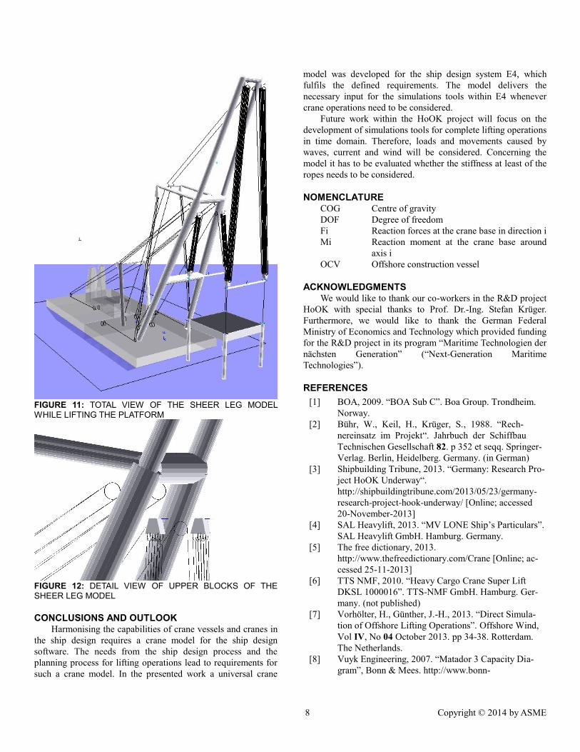
shown in Figure 1. The crane model itself consists of 15
different bodies for the A-frame, the span bracing, the flying jib,
and the four hooks and the blocks for the pulleys. For the lifting
operation two spreader bars have been used to regulate the
distance between the two main hooks and the two hooks on the
fly jib respectively. These spreader bars, the platform and the
shackles are modelled as additional bodies which are coupled to
the hooks and the platform. The grommets are modelled as
pulleys without sheaves. In the model the luffing angle for the
A-frame and the flying jib as well as the hook height for each of
the four hooks can be controlled independently.
8 Copyright © 2014 by ASME
FIGURE 11: TOTAL VIEW OF THE SHEER LEG MODEL WHILE LIFTING THE PLATFORM
FIGURE 12: DETAIL VIEW OF UPPER BLOCKS OF THE SHEER LEG MODEL
CONCLUSIONS AND OUTLOOK Harmonising the capabilities of crane vessels and cranes in
the ship design requires a crane model for the ship design
software. The needs from the ship design process and the
planning process for lifting operations lead to requirements for
such a crane model. In the presented work a universal crane
model was developed for the ship design system E4, which
fulfils the defined requirements. The model delivers the
necessary input for the simulations tools within E4 whenever
crane operations need to be considered.
Future work within the HoOK project will focus on the
development of simulations tools for complete lifting operations
in time domain. Therefore, loads and movements caused by
waves, current and wind will be considered. Concerning the
model it has to be evaluated whether the stiffness at least of the
ropes needs to be considered.
NOMENCLATURE COG Centre of gravity
DOF Degree of freedom
Fi Reaction forces at the crane base in direction i
Mi Reaction moment at the crane base around
axis i
OCV Offshore construction vessel
ACKNOWLEDGMENTS We would like to thank our co-workers in the R&D project
HoOK with special thanks to Prof. Dr.-Ing. Stefan Krüger.
Furthermore, we would like to thank the German Federal
Ministry of Economics and Technology which provided funding
for the R&D project in its program “Maritime Technologien der
nächsten Generation” (“Next-Generation Maritime
Technologies”).
REFERENCES
[1] BOA, 2009. “BOA Sub C”. Boa Group. Trondheim.
Norway.
[2] Bühr, W., Keil, H., Krüger, S., 1988. “Rech-
nereinsatz im Projekt“. Jahrbuch der Schiffbau
Technischen Gesellschaft 82. p 352 et seqq. Springer-
Verlag. Berlin, Heidelberg. Germany. (in German)
[3] Shipbuilding Tribune, 2013. “Germany: Research Pro-
ject HoOK Underway“.
http://shipbuildingtribune.com/2013/05/23/germany-
research-project-hook-underway/ [Online; accessed
20-November-2013]
[4] SAL Heavylift, 2013. “MV LONE Ship’s Particulars”.
SAL Heavylift GmbH. Hamburg. Germany.
[5] The free dictionary, 2013.
http://www.thefreedictionary.com/Crane [Online; ac-
cessed 25-11-2013]
[6] TTS NMF, 2010. “Heavy Cargo Crane Super Lift
DKSL 1000016”. TTS-NMF GmbH. Hamburg. Ger-
many. (not published)
[7] Vorhölter, H., Günther, J.-H., 2013. “Direct Simula-
tion of Offshore Lifting Operations”. Offshore Wind,
Vol IV, No 04 October 2013. pp 34-38. Rotterdam.
The Netherlands.
[8] Vuyk Engineering, 2007. “Matador 3 Capacity Dia-
gram”, Bonn & Mees. http://www.bonn-

9 Copyright © 2014 by ASME
mees.com/36/matador-3.html / [Online; accessed 25-
November-2013]
[9] Woernle, C., 2011. “Mehrkörpersysteme – Eine
Einführung in die Kinematik und Dynamik von Sys-
temen starrer Körper”. Springer-Verlag. Berlin, Hei-
delberg. Germany. (in German)
ANNEX A: DATA FOR SIMPLE CRANE MODEL
TABLE 1: DESIGN DATA FOR SIMPLE CRANE MODEL
Dimension Value
Column height 10 m
Column COG 5 m
Column weight 50 t
Crane house height 20 m
Crane house COG 10 m
Crane house weight 150 t
Jib lenght 20 m
Jib COG 10 m
Jib weight 75 t
Hook weight 5 t
Sheave diameter 0.5 m
TABLE 2: LOAD CASE PARAMETER
Dimension Value
Luffing angle 45°
Distance hook jib tip 20 m
Load mass 160 t
Heel 5°
Trim 5°