Universal Cover page 2.9.2014 - Penn State Engineering integrated design analysis, ... The...
48
Transcript of Universal Cover page 2.9.2014 - Penn State Engineering integrated design analysis, ... The...

AEVITAS | STRUCTURAL
Team Registration Number: 03-2014 STRUCTURAL | 0
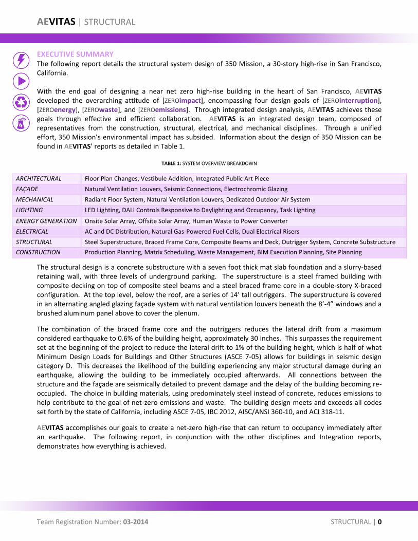
EXECUTIVE SUMMARY The following report details the structural system design of 350 Mission, a 30-story high-rise in San Francisco, California. With the end goal of designing a near net zero high-rise building in the heart of San Francisco, AEVITAS developed the overarching attitude of [ZEROimpact], encompassing four design goals of [ZEROinterruption], [ZEROenergy], [ZEROwaste], and [ZEROemissions]. Through integrated design analysis, AEVITAS achieves these goals through effective and efficient collaboration. AEVITAS is an integrated design team, composed of representatives from the construction, structural, electrical, and mechanical disciplines. Through a unified effort, 350 Mission’s environmental impact has subsided. Information about the design of 350 Mission can be found in AEVITAS’ reports as detailed in Table 1.
TABLE 1: SYSTEM OVERVIEW BREAKDOWN
ARCHITECTURAL Floor Plan Changes, Vestibule Addition, Integrated Public Art Piece
FAÇADE Natural Ventilation Louvers, Seismic Connections, Electrochromic Glazing
MECHANICAL Radiant Floor System, Natural Ventilation Louvers, Dedicated Outdoor Air System
LIGHTING LED Lighting, DALI Controls Responsive to Daylighting and Occupancy, Task Lighting
ENERGY GENERATION Onsite Solar Array, Offsite Solar Array, Human Waste to Power Converter
ELECTRICAL AC and DC Distribution, Natural Gas-Powered Fuel Cells, Dual Electrical Risers
STRUCTURAL Steel Superstructure, Braced Frame Core, Composite Beams and Deck, Outrigger System, Concrete Substructure
CONSTRUCTION Production Planning, Matrix Scheduling, Waste Management, BIM Execution Planning, Site Planning
The structural design is a concrete substructure with a seven foot thick mat slab foundation and a slurry-based retaining wall, with three levels of underground parking. The superstructure is a steel framed building with composite decking on top of composite steel beams and a steel braced frame core in a double-story X-braced configuration. At the top level, below the roof, are a series of 14’ tall outriggers. The superstructure is covered in an alternating angled glazing façade system with natural ventilation louvers beneath the 8’-4” windows and a brushed aluminum panel above to cover the plenum.
The combination of the braced frame core and the outriggers reduces the lateral drift from a maximum considered earthquake to 0.6% of the building height, approximately 30 inches. This surpasses the requirement set at the beginning of the project to reduce the lateral drift to 1% of the building height, which is half of what Minimum Design Loads for Buildings and Other Structures (ASCE 7-05) allows for buildings in seismic design category D. This decreases the likelihood of the building experiencing any major structural damage during an earthquake, allowing the building to be immediately occupied afterwards. All connections between the structure and the façade are seismically detailed to prevent damage and the delay of the building becoming re-occupied. The choice in building materials, using predominately steel instead of concrete, reduces emissions to help contribute to the goal of net-zero emissions and waste. The building design meets and exceeds all codes set forth by the state of California, including ASCE 7-05, IBC 2012, AISC/ANSI 360-10, and ACI 318-11.
AEVITAS accomplishes our goals to create a net-zero high-rise that can return to occupancy immediately after an earthquake. The following report, in conjunction with the other disciplines and Integration reports, demonstrates how everything is achieved.
AEVITAS | STRUCTURAL
Team Registration Number: 03-2014 STRUCTURAL | 1
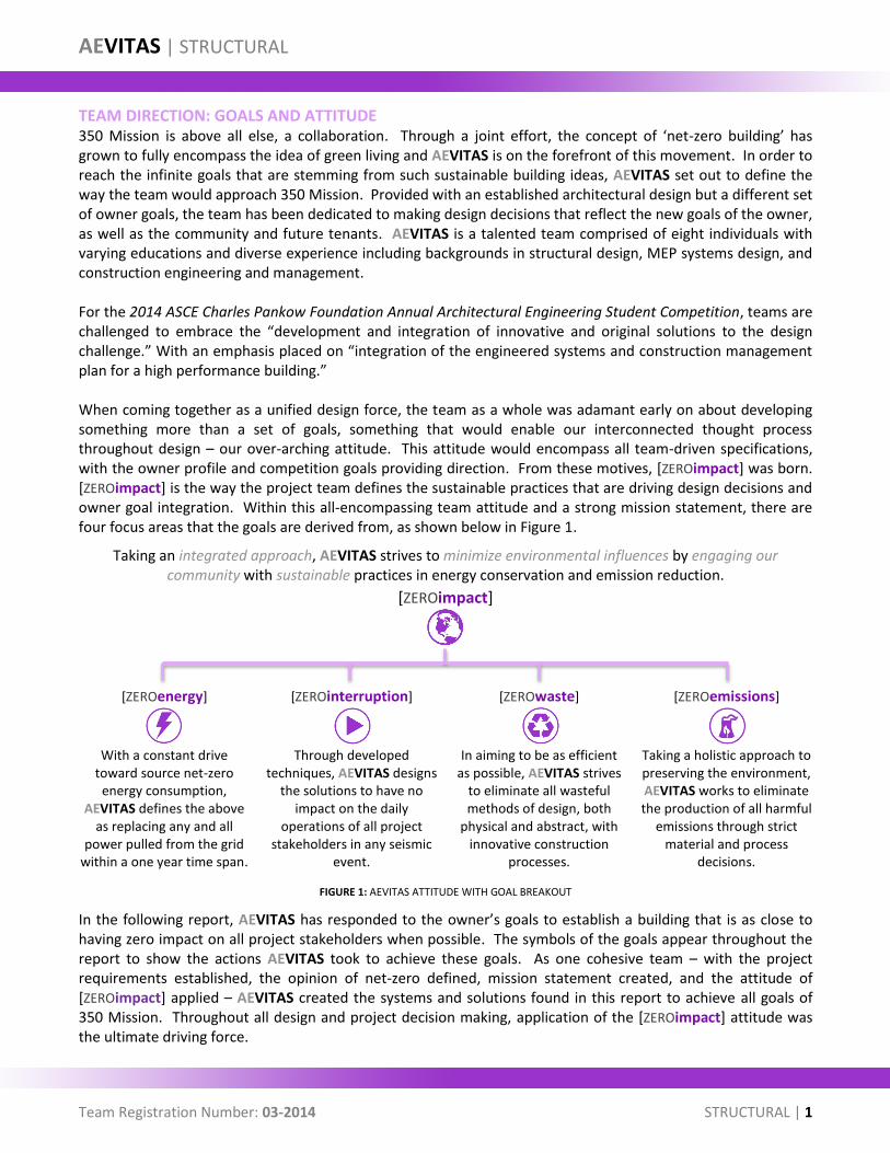
TEAM DIRECTION: GOALS AND ATTITUDE 350 Mission is above all else, a collaboration. Through a joint effort, the concept of ‘net-zero building’ has grown to fully encompass the idea of green living and AEVITAS is on the forefront of this movement. In order to reach the infinite goals that are stemming from such sustainable building ideas, AEVITAS set out to define the way the team would approach 350 Mission. Provided with an established architectural design but a different set of owner goals, the team has been dedicated to making design decisions that reflect the new goals of the owner, as well as the community and future tenants. AEVITAS is a talented team comprised of eight individuals with varying educations and diverse experience including backgrounds in structural design, MEP systems design, and construction engineering and management. For the 2014 ASCE Charles Pankow Foundation Annual Architectural Engineering Student Competition, teams are challenged to embrace the “development and integration of innovative and original solutions to the design challenge.” With an emphasis placed on “integration of the engineered systems and construction management plan for a high performance building.” When coming together as a unified design force, the team as a whole was adamant early on about developing something more than a set of goals, something that would enable our interconnected thought process throughout design – our over-arching attitude. This attitude would encompass all team-driven specifications, with the owner profile and competition goals providing direction. From these motives, [ZEROimpact] was born. [ZEROimpact] is the way the project team defines the sustainable practices that are driving design decisions and owner goal integration. Within this all-encompassing team attitude and a strong mission statement, there are four focus areas that the goals are derived from, as shown below in Figure 1.
Taking an integrated approach, AEVITAS strives to minimize environmental influences by engaging our community with sustainable practices in energy conservation and emission reduction.
[ZEROimpact]
[ZEROenergy] [ZEROinterruption] [ZEROwaste] [ZEROemissions]
With a constant drive
toward source net-zero energy consumption,
AEVITAS defines the above as replacing any and all
power pulled from the grid within a one year time span.
Through developed techniques, AEVITAS designs
the solutions to have no impact on the daily
operations of all project stakeholders in any seismic
event.
In aiming to be as efficient as possible, AEVITAS strives
to eliminate all wasteful methods of design, both
physical and abstract, with innovative construction
processes.
Taking a holistic approach to preserving the environment, AEVITAS works to eliminate the production of all harmful
emissions through strict material and process
decisions.
FIGURE 1: AEVITAS ATTITUDE WITH GOAL BREAKOUT
In the following report, AEVITAS has responded to the owner’s goals to establish a building that is as close to having zero impact on all project stakeholders when possible. The symbols of the goals appear throughout the report to show the actions AEVITAS took to achieve these goals. As one cohesive team – with the project requirements established, the opinion of net-zero defined, mission statement created, and the attitude of [ZEROimpact] applied – AEVITAS created the systems and solutions found in this report to achieve all goals of 350 Mission. Throughout all design and project decision making, application of the [ZEROimpact] attitude was the ultimate driving force.
AEVITAS | STRUCTURAL
Team Registration Number: 03-2014 STRUCTURAL | 2
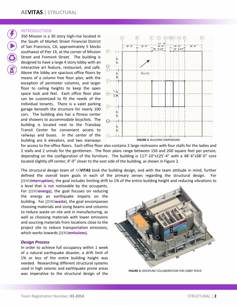
INTRODUCTION 350 Mission is a 30 story high-rise located in the South of Market Street Financial District of San Francisco, CA, approximately 5 blocks southwest of Pier 14, at the corner of Mission Street and Fremont Street. The building is designed to have a large 4 story lobby with an interactive art feature, restaurant, and café. Above the lobby are spacious office floors by means of a column free floor plan, with the exception of perimeter columns, and larger floor to ceiling heights to keep the open space look and feel. Each office floor plan can be customized to fit the needs of the individual tenants. There is a valet parking garage beneath the structure for nearly 100 cars. The building also has a fitness center and showers to accommodate bicyclists. The building is located next to the Transbay Transit Center for convenient access to railways and buses. In the center of the building are 6 elevators, and two stairways for access to the office floors. Each office floor also contains 2 large restrooms with four stalls for the ladies and 2 stalls and 2 urinals for the gentlemen. The floor plans range between 150 and 200 square feet per person, depending on the configuration of the furniture. The building is 117’-10”x125’-4” with a 48’-6”x38’-0” core located slightly off-center, 9’-0” closer to the east side of the building, as shown in Figure 2.
The structural design team of AEVITAS took the building design, and with the team attitude in mind, further defined the overall team goals in each of the primary zeroes regarding the structural design. For [ZEROinterruption], the goal includes limiting drift to 1% of the entire building height and reducing vibrations to a level that is not noticeable by the occupants. For [ZEROenergy], the goal focuses on reducing the energy an earthquake imparts on the building. For [ZEROwaste], the goal encompasses choosing materials and sizing beams and columns to reduce waste on site and in manufacturing, as well as choosing materials with lower emissions and sourcing materials from locations close to the project site to reduce transportation emissions, which works towards [ZEROemissions].
Design Process In order to achieve full occupancy within 1 week of a natural earthquake disaster, a drift limit of 1% or less of the entire building height was needed. Researching different structural systems used in high seismic and earthquake prone areas was imperative to the structural design of the
FIGURE 2: BUILDING DIMENSIONS
FIGURE 3: DISCIPLINE COLLABORATION FOR LOBBY SPACE
AEVITAS | STRUCTURAL
Team Registration Number: 03-2014 STRUCTURAL | 3
building. The results from the decision making process can be found on page SD3 of the Supporting Documents. Advanced computer analysis and design modeling provided feedback to help maximize the efficiency of the design beyond hand calculations.
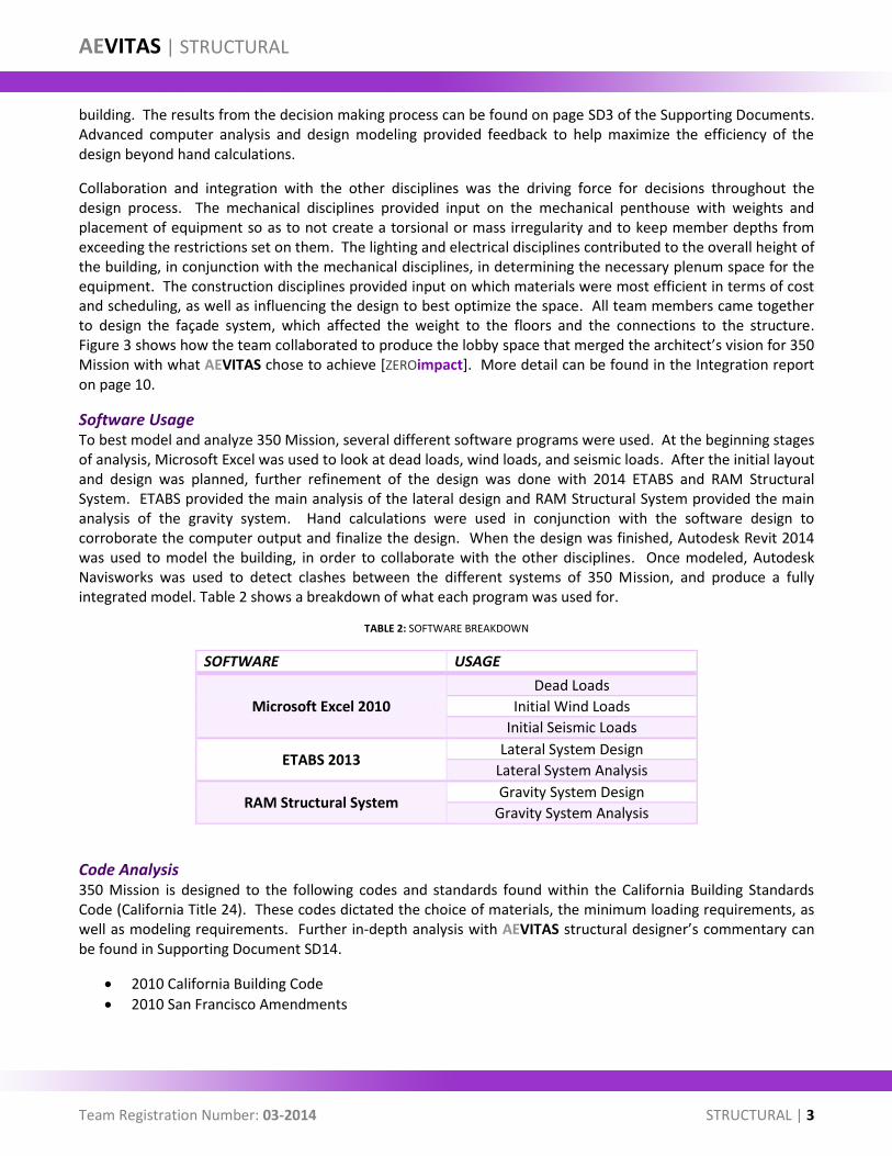
Collaboration and integration with the other disciplines was the driving force for decisions throughout the design process. The mechanical disciplines provided input on the mechanical penthouse with weights and placement of equipment so as to not create a torsional or mass irregularity and to keep member depths from exceeding the restrictions set on them. The lighting and electrical disciplines contributed to the overall height of the building, in conjunction with the mechanical disciplines, in determining the necessary plenum space for the equipment. The construction disciplines provided input on which materials were most efficient in terms of cost and scheduling, as well as influencing the design to best optimize the space. All team members came together to design the façade system, which affected the weight to the floors and the connections to the structure. Figure 3 shows how the team collaborated to produce the lobby space that merged the architect’s vision for 350 Mission with what AEVITAS chose to achieve [ZEROimpact]. More detail can be found in the Integration report on page 10.
Software Usage To best model and analyze 350 Mission, several different software programs were used. At the beginning stages of analysis, Microsoft Excel was used to look at dead loads, wind loads, and seismic loads. After the initial layout and design was planned, further refinement of the design was done with 2014 ETABS and RAM Structural System. ETABS provided the main analysis of the lateral design and RAM Structural System provided the main analysis of the gravity system. Hand calculations were used in conjunction with the software design to corroborate the computer output and finalize the design. When the design was finished, Autodesk Revit 2014 was used to model the building, in order to collaborate with the other disciplines. Once modeled, Autodesk Navisworks was used to detect clashes between the different systems of 350 Mission, and produce a fully integrated model. Table 2 shows a breakdown of what each program was used for.
TABLE 2: SOFTWARE BREAKDOWN
SOFTWARE USAGE
Microsoft Excel 2010
Dead Loads
Initial Wind Loads
Initial Seismic Loads
ETABS 2013 Lateral System Design
Lateral System Analysis
RAM Structural System Gravity System Design
Gravity System Analysis
Code Analysis 350 Mission is designed to the following codes and standards found within the California Building Standards Code (California Title 24). These codes dictated the choice of materials, the minimum loading requirements, as well as modeling requirements. Further in-depth analysis with AEVITAS structural designer’s commentary can be found in Supporting Document SD14.
2010 California Building Code
2010 San Francisco Amendments
AEVITAS | STRUCTURAL
Team Registration Number: 03-2014 STRUCTURAL | 4
Minimum Design Loads for Buildings and Other Structures (ASCE 7-05) [What San Francisco, CA code currently uses]
Minimum Design Loads for Buildings and Other Structures (ASCE 7-10) [What code is heading towards, midway through design]
American Concrete Institute (ACI) 318-11
American Institute of Steel Construction (AISC/ANSI) 360-10
American Institute of Steel Construction (AISC/ANSI) 341-10
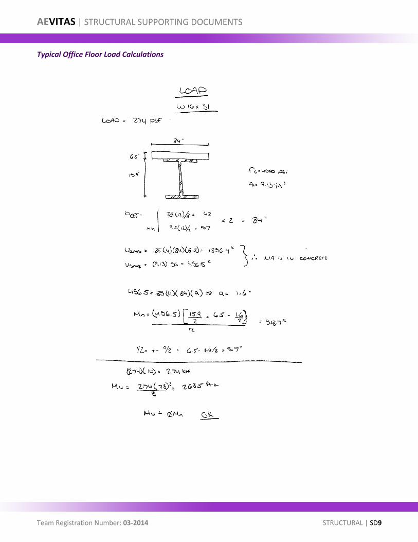
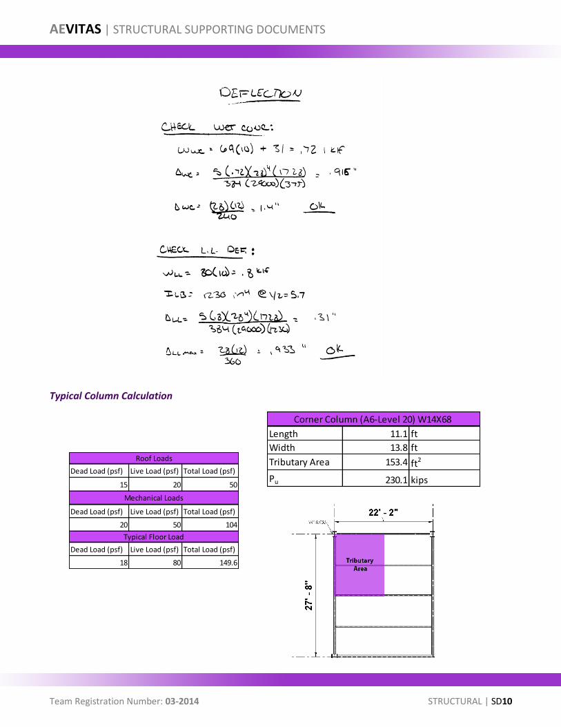
LOAD ANALYSIS Gravity The open floor plan design allows for corridors throughout the space; since code requires 80 pounds per square foot (psf) live load for corridors above the first floor to account for people leaving in the event of an evacuation of the building and not being able to define a corridor clearly in the layout, the live load was chosen to be 80 psf throughout a typical floor. Additionally, since a typical office load of 50 psf and a partition load of 20 psf equaled 70 psf, which is 10 psf less than the more conservative 80 psf, was another reason for choosing the larger floor load. A live load reduction does not apply because the entire floor can be considered a means of egress, as there is no directly specified emergency evacuation route for any location on the floor.
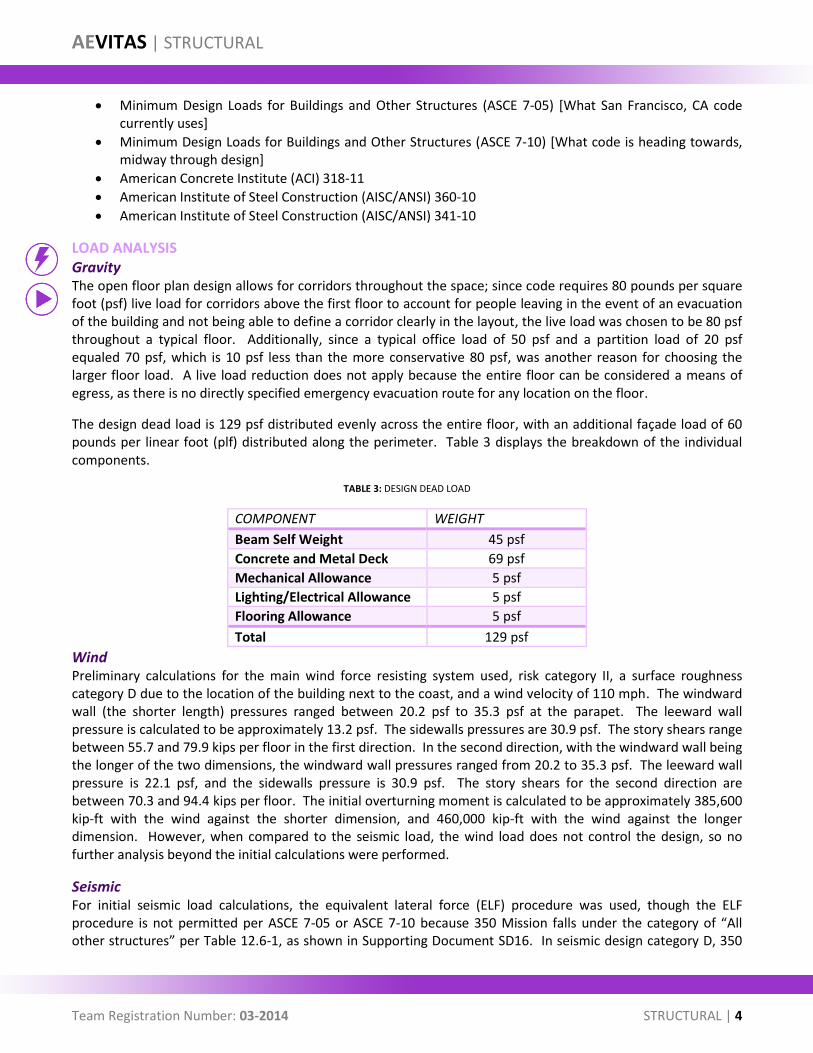
The design dead load is 129 psf distributed evenly across the entire floor, with an additional façade load of 60 pounds per linear foot (plf) distributed along the perimeter. Table 3 displays the breakdown of the individual components.
TABLE 3: DESIGN DEAD LOAD
COMPONENT WEIGHT
Beam Self Weight 45 psf
Concrete and Metal Deck 69 psf
Mechanical Allowance 5 psf
Lighting/Electrical Allowance 5 psf
Flooring Allowance 5 psf
Total 129 psf
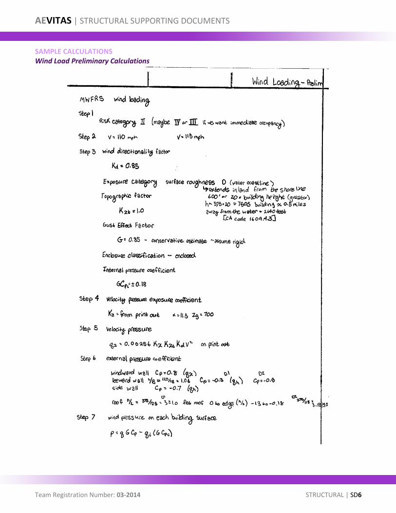
Wind Preliminary calculations for the main wind force resisting system used, risk category II, a surface roughness category D due to the location of the building next to the coast, and a wind velocity of 110 mph. The windward wall (the shorter length) pressures ranged between 20.2 psf to 35.3 psf at the parapet. The leeward wall pressure is calculated to be approximately 13.2 psf. The sidewalls pressures are 30.9 psf. The story shears range between 55.7 and 79.9 kips per floor in the first direction. In the second direction, with the windward wall being the longer of the two dimensions, the windward wall pressures ranged from 20.2 to 35.3 psf. The leeward wall pressure is 22.1 psf, and the sidewalls pressure is 30.9 psf. The story shears for the second direction are between 70.3 and 94.4 kips per floor. The initial overturning moment is calculated to be approximately 385,600 kip-ft with the wind against the shorter dimension, and 460,000 kip-ft with the wind against the longer dimension. However, when compared to the seismic load, the wind load does not control the design, so no further analysis beyond the initial calculations were performed.
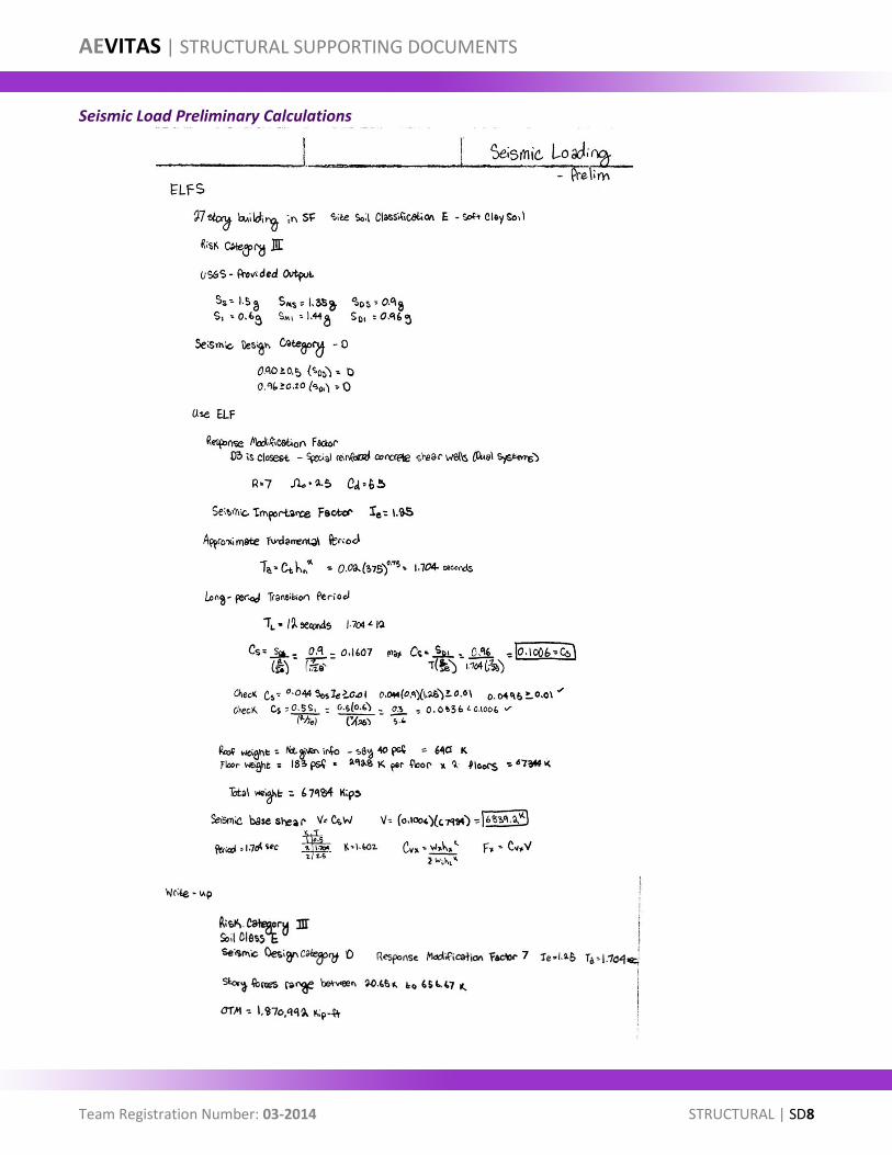
Seismic For initial seismic load calculations, the equivalent lateral force (ELF) procedure was used, though the ELF procedure is not permitted per ASCE 7-05 or ASCE 7-10 because 350 Mission falls under the category of “All other structures” per Table 12.6-1, as shown in Supporting Document SD16. In seismic design category D, 350
AEVITAS | STRUCTURAL
Team Registration Number: 03-2014 STRUCTURAL | 5
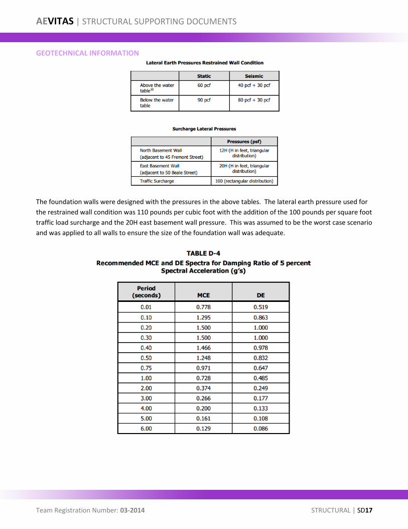
Mission is larger than three stories in height, has an irregular structure due to the lobby floors, and has a period greater than 1.6 seconds, therefore falling into the category of “All other structures.” An advanced method is required, such as Modal Response Spectrum Analysis or Seismic Response History Procedures. To conduct the advanced analytical procedure, computer modeling and analysis software was used. ELF and modeling were used for initial sizing and system selection. By the end, further computer-aided calculations in ETABS were used to calculate the Modal Response Spectrum Analysis (MSRA). A response modification factor of 7 was used for the ELF procedure, with a soil class E and risk category II, and a seismic importance factor of 1.25. The story forces range between 20.7 and 656.7 kips per floor. The overturning moment was found to be approximately 1,871,000 kip-ft. The initial approximation for the fundamental period was 1.704 seconds. These seismic forces controlled over the wind forces, and were developed further with the use of ETABS, with the addition of the recommended maximum considered earthquake (MCE), and the design earthquake (DE), spectra for a damping ratio of 5% spectral acceleration from the geotechnical report, found in Supporting Document SD17, for loading.
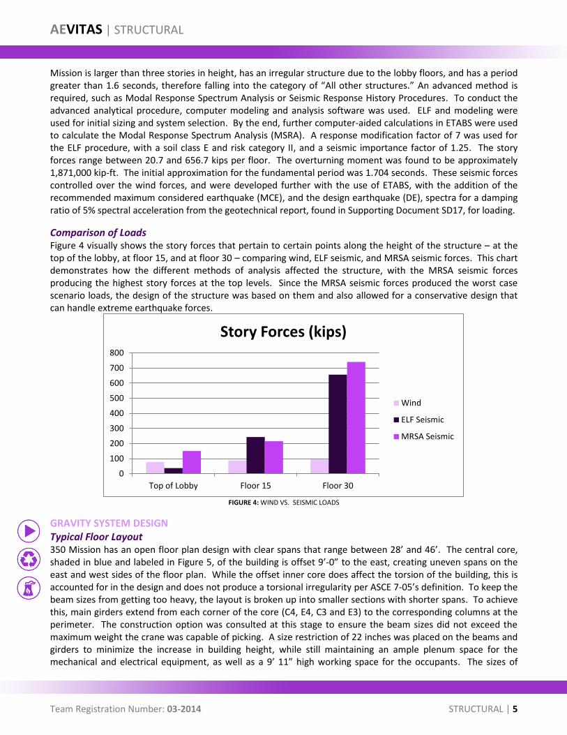
Comparison of Loads Figure 4 visually shows the story forces that pertain to certain points along the height of the structure – at the top of the lobby, at floor 15, and at floor 30 – comparing wind, ELF seismic, and MRSA seismic forces. This chart demonstrates how the different methods of analysis affected the structure, with the MRSA seismic forces producing the highest story forces at the top levels. Since the MRSA seismic forces produced the worst case scenario loads, the design of the structure was based on them and also allowed for a conservative design that can handle extreme earthquake forces.
FIGURE 4: WIND VS. SEISMIC LOADS
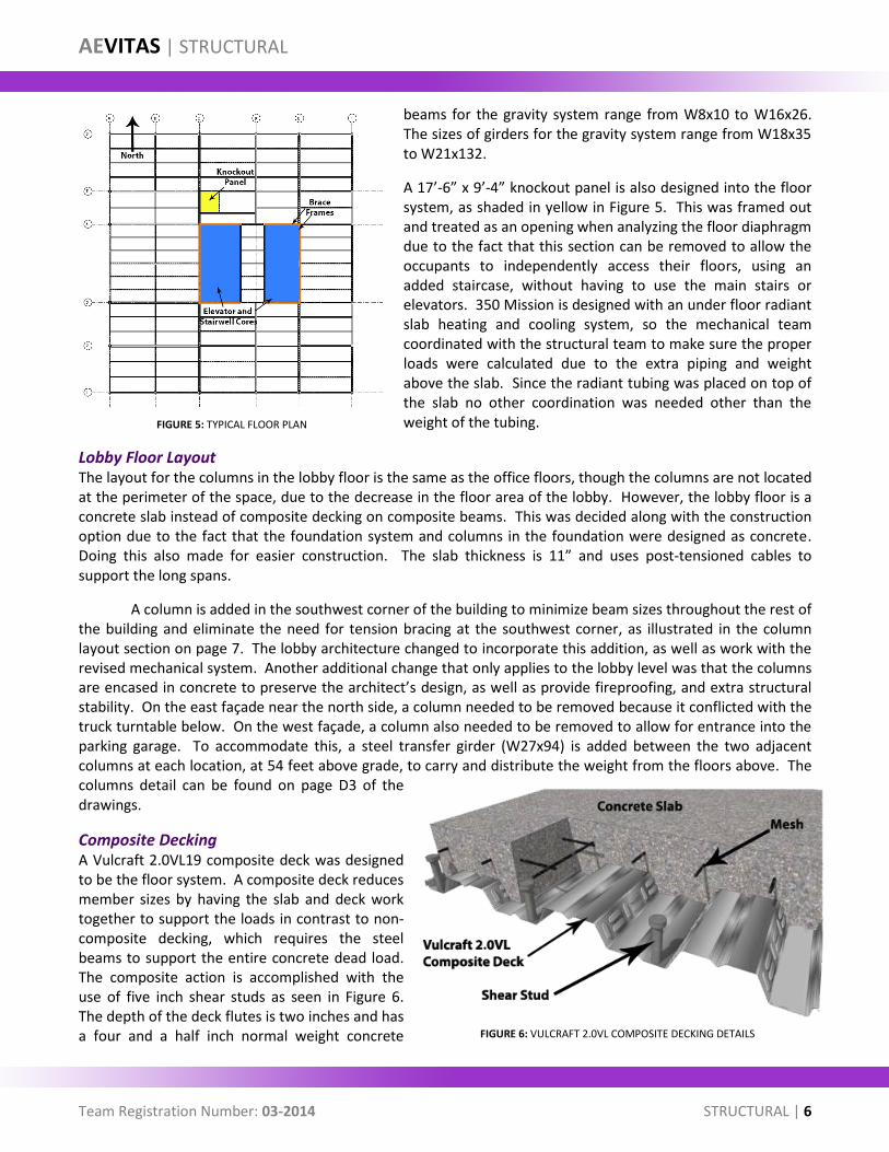
GRAVITY SYSTEM DESIGN Typical Floor Layout 350 Mission has an open floor plan design with clear spans that range between 28’ and 46’. The central core, shaded in blue and labeled in Figure 5, of the building is offset 9’-0” to the east, creating uneven spans on the east and west sides of the floor plan. While the offset inner core does affect the torsion of the building, this is accounted for in the design and does not produce a torsional irregularity per ASCE 7-05’s definition. To keep the beam sizes from getting too heavy, the layout is broken up into smaller sections with shorter spans. To achieve this, main girders extend from each corner of the core (C4, E4, C3 and E3) to the corresponding columns at the perimeter. The construction option was consulted at this stage to ensure the beam sizes did not exceed the maximum weight the crane was capable of picking. A size restriction of 22 inches was placed on the beams and girders to minimize the increase in building height, while still maintaining an ample plenum space for the mechanical and electrical equipment, as well as a 9’ 11” high working space for the occupants. The sizes of
0
100
200
300
400
500
600
700
800
Top of Lobby Floor 15 Floor 30
Story Forces (kips)
Wind
ELF Seismic
MRSA Seismic
AEVITAS | STRUCTURAL
Team Registration Number: 03-2014 STRUCTURAL | 6
beams for the gravity system range from W8x10 to W16x26. The sizes of girders for the gravity system range from W18x35 to W21x132.
A 17’-6” x 9’-4” knockout panel is also designed into the floor system, as shaded in yellow in Figure 5. This was framed out and treated as an opening when analyzing the floor diaphragm due to the fact that this section can be removed to allow the occupants to independently access their floors, using an added staircase, without having to use the main stairs or elevators. 350 Mission is designed with an under floor radiant slab heating and cooling system, so the mechanical team coordinated with the structural team to make sure the proper loads were calculated due to the extra piping and weight above the slab. Since the radiant tubing was placed on top of the slab no other coordination was needed other than the weight of the tubing.
Lobby Floor Layout The layout for the columns in the lobby floor is the same as the office floors, though the columns are not located at the perimeter of the space, due to the decrease in the floor area of the lobby. However, the lobby floor is a concrete slab instead of composite decking on composite beams. This was decided along with the construction option due to the fact that the foundation system and columns in the foundation were designed as concrete. Doing this also made for easier construction. The slab thickness is 11” and uses post-tensioned cables to support the long spans.
A column is added in the southwest corner of the building to minimize beam sizes throughout the rest of the building and eliminate the need for tension bracing at the southwest corner, as illustrated in the column layout section on page 7. The lobby architecture changed to incorporate this addition, as well as work with the revised mechanical system. Another additional change that only applies to the lobby level was that the columns are encased in concrete to preserve the architect’s design, as well as provide fireproofing, and extra structural stability. On the east façade near the north side, a column needed to be removed because it conflicted with the truck turntable below. On the west façade, a column also needed to be removed to allow for entrance into the parking garage. To accommodate this, a steel transfer girder (W27x94) is added between the two adjacent columns at each location, at 54 feet above grade, to carry and distribute the weight from the floors above. The columns detail can be found on page D3 of the drawings.
Composite Decking A Vulcraft 2.0VL19 composite deck was designed to be the floor system. A composite deck reduces member sizes by having the slab and deck work together to support the loads in contrast to non-composite decking, which requires the steel beams to support the entire concrete dead load. The composite action is accomplished with the use of five inch shear studs as seen in Figure 6. The depth of the deck flutes is two inches and has a four and a half inch normal weight concrete FIGURE 6: VULCRAFT 2.0VL COMPOSITE DECKING DETAILS
FIGURE 5: TYPICAL FLOOR PLAN
AEVITAS | STRUCTURAL
Team Registration Number: 03-2014 STRUCTURAL | 7
topping making the total deck thickness six and half inches, which allows for the deck to have a two hour fire rating with no additional fireproofing required. Studs are field welded to the deck along with the deck being welded to the members. The deck spans north to south, perpendicular to the beams and is designed without the need for shoring during construction, which shortens construction time, as well as allows the lower floors to be worked on sooner.
Since the phasing of the construction had the façade being placed 6 floors behind the concrete for the decking, admixtures, such as sodium thiocyanate or calcium nitrite, were added to the concrete. This allowed for faster curing in the cold and wet environment of San Francisco without compromising the strength of the system, requiring epoxy-coated reinforcement or delay in the construction schedule.
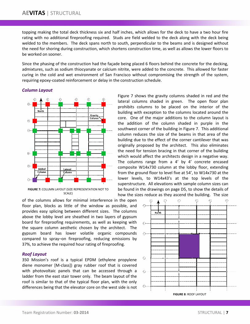
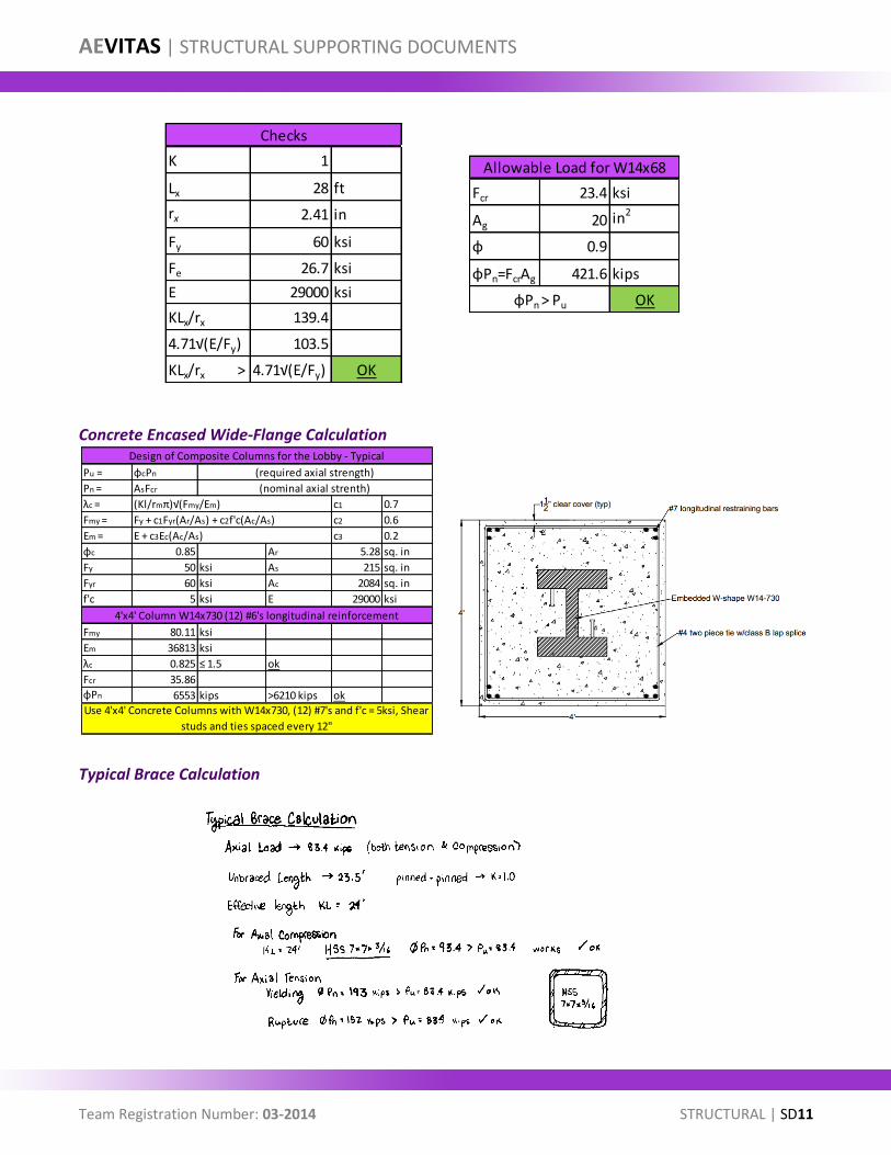
Column Layout Figure 7 shows the gravity columns shaded in red and the lateral columns shaded in green. The open floor plan prohibits columns to be placed on the interior of the building with exception to the columns located around the core. One of the major additions to the column layout is the addition of the column shaded in purple in the southwest corner of the building in Figure 7. This additional column reduces the size of the beams in that area of the building due to the effect of the corner cantilever that was originally proposed by the architect. This also eliminates the need for tension bracing in that corner of the building which would affect the architects design in a negative way. The columns range from a 4’ by 4’ concrete encased composite W14x730 column at the lobby floor, extending from the ground floor to level five at 54’, to W14x730 at the lower levels, to W14x43’s at the top levels of the superstructure. All elevations with sample column sizes can be found in the drawings on page D5, to show the details of how the sizes reduce as they ascend the building. The size
of the columns allows for minimal interference in the open floor plan, blocks as little of the window as possible, and provides easy splicing between different sizes. The columns above the lobby level are sheathed in two layers of gypsum board for fireproofing requirements, as well as keeping with the square column aesthetic chosen by the architect. The gypsum board has lower volatile organic compounds compared to spray–on fireproofing, reducing emissions by 37%, to achieve the required hour rating of fireproofing.
Roof Layout 350 Mission’s roof is a typical EPDM (ethylene propylene diene monomer [M-class]) gray rubber roof that is covered with photovoltaic panels that can be accessed through a ladder from the east stair tower only. The beam layout of the roof is similar to that of the typical floor plan, with the only differences being that the elevator core on the west side is not
FIGURE 7: COLUMN LAYOUT (SIZE REPRESENTATION NOT TO SCALE)
FIGURE 8: ROOF LAYOUT
AEVITAS | STRUCTURAL
Team Registration Number: 03-2014 STRUCTURAL | 8
open for elevator or stair tower access to the roof, but is instead open to the cooling tower located on the mechanical penthouse floor, within the boundary of the core, as shown in the purple shaded region in Figure 8. A three-dimensional view of the cooling tower can be found in the mechanical penthouse layout section on page 8. The members have no size restrictions due to the outrigger level below and range from W8x10 to the largest being a W30x90. Discussions between the structural team and the construction team transpired to compare the cost and construction differences between deeper and lighter beams or smaller and heavier beams, but ultimately the weight of the beams was the deciding factor for the design. The depths of the deepest roof beams are 30% deeper than the deepest of a typical floor, but 65% lighter than that of a typical floor. This change is due to loads on the roof including several arrays of photovoltaic panels and a live load for maintenance of the panels.
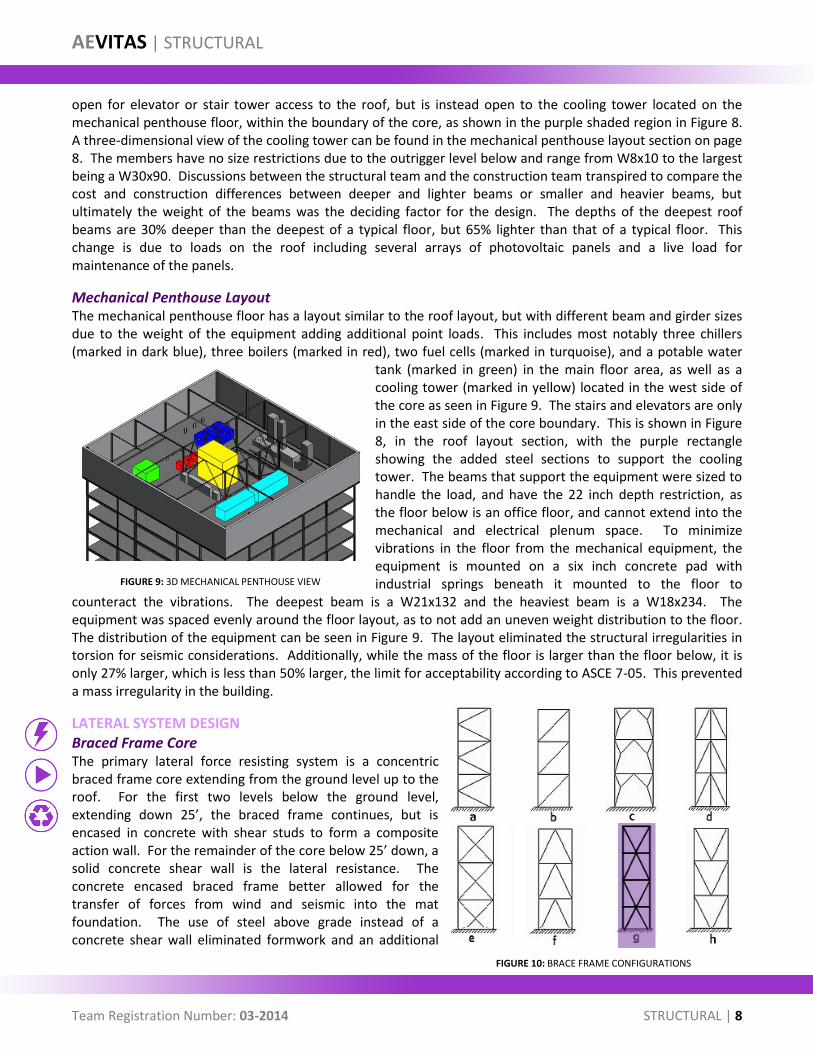
Mechanical Penthouse Layout The mechanical penthouse floor has a layout similar to the roof layout, but with different beam and girder sizes due to the weight of the equipment adding additional point loads. This includes most notably three chillers (marked in dark blue), three boilers (marked in red), two fuel cells (marked in turquoise), and a potable water
tank (marked in green) in the main floor area, as well as a cooling tower (marked in yellow) located in the west side of the core as seen in Figure 9. The stairs and elevators are only in the east side of the core boundary. This is shown in Figure 8, in the roof layout section, with the purple rectangle showing the added steel sections to support the cooling tower. The beams that support the equipment were sized to handle the load, and have the 22 inch depth restriction, as the floor below is an office floor, and cannot extend into the mechanical and electrical plenum space. To minimize vibrations in the floor from the mechanical equipment, the equipment is mounted on a six inch concrete pad with industrial springs beneath it mounted to the floor to
counteract the vibrations. The deepest beam is a W21x132 and the heaviest beam is a W18x234. The equipment was spaced evenly around the floor layout, as to not add an uneven weight distribution to the floor. The distribution of the equipment can be seen in Figure 9. The layout eliminated the structural irregularities in torsion for seismic considerations. Additionally, while the mass of the floor is larger than the floor below, it is only 27% larger, which is less than 50% larger, the limit for acceptability according to ASCE 7-05. This prevented a mass irregularity in the building.
LATERAL SYSTEM DESIGN Braced Frame Core The primary lateral force resisting system is a concentric braced frame core extending from the ground level up to the roof. For the first two levels below the ground level, extending down 25’, the braced frame continues, but is encased in concrete with shear studs to form a composite action wall. For the remainder of the core below 25’ down, a solid concrete shear wall is the lateral resistance. The concrete encased braced frame better allowed for the transfer of forces from wind and seismic into the mat foundation. The use of steel above grade instead of a concrete shear wall eliminated formwork and an additional
FIGURE 10: BRACE FRAME CONFIGURATIONS
FIGURE 9: 3D MECHANICAL PENTHOUSE VIEW
AEVITAS | STRUCTURAL
Team Registration Number: 03-2014 STRUCTURAL | 9
sub-contractor, as well as shortened the construction process. The braced frame core was constructed two stories above any given floor, which helped maintain the lateral stability during construction, in the event of an earthquake occurring during construction.
The chosen brace design was a double-story X pattern, as shown as letter ‘g’ in Figure 10. This design allowed for the members to take both tension and compression during seismic activity, but eliminates the costly connections between the cross connection of a single-story X pattern, as shown in letter ‘e’ in Figure 10. The brace elements are HSS tubes ranging between HSS3x3x3/16 to HSS10x10x5/8, with the heavier braces in the lower levels, with lengths between 12’-9” to 31’-4”. The longer lengths are in the lobby section of the core, as well in the mechanical penthouse floor, with the extended floor-to-floor height. The braced frame design allowed for mechanical and electrical equipment
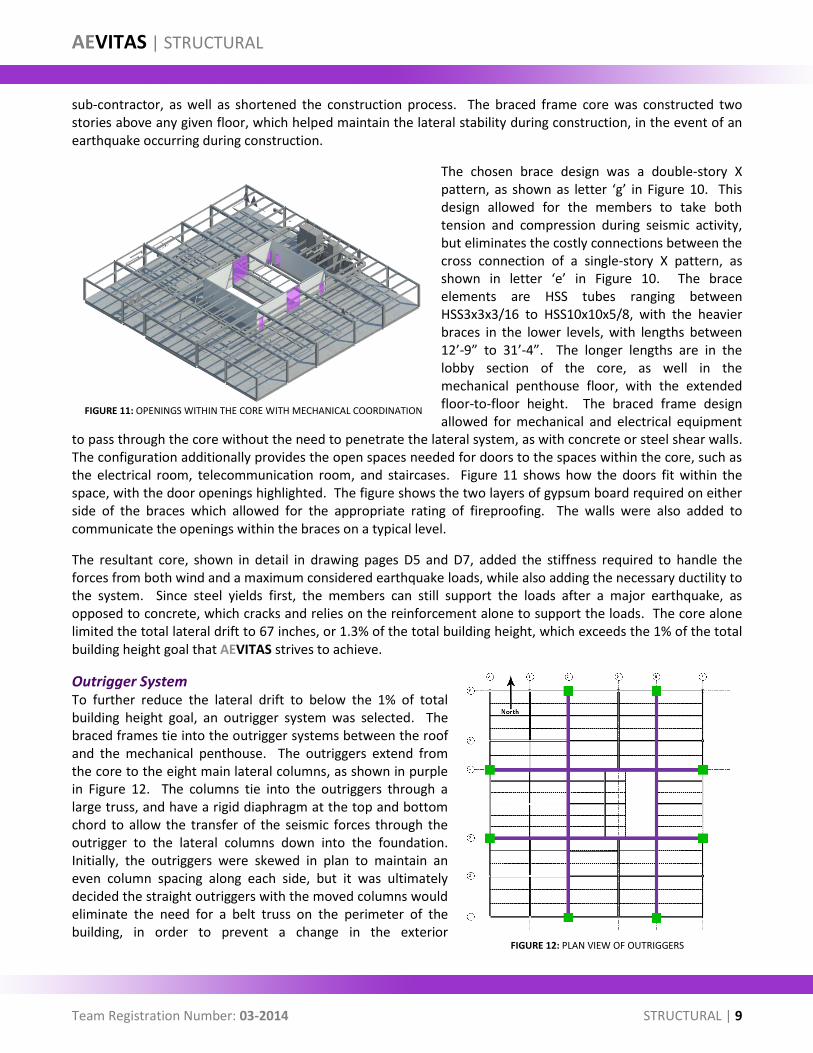
to pass through the core without the need to penetrate the lateral system, as with concrete or steel shear walls. The configuration additionally provides the open spaces needed for doors to the spaces within the core, such as the electrical room, telecommunication room, and staircases. Figure 11 shows how the doors fit within the space, with the door openings highlighted. The figure shows the two layers of gypsum board required on either side of the braces which allowed for the appropriate rating of fireproofing. The walls were also added to communicate the openings within the braces on a typical level.
The resultant core, shown in detail in drawing pages D5 and D7, added the stiffness required to handle the forces from both wind and a maximum considered earthquake loads, while also adding the necessary ductility to the system. Since steel yields first, the members can still support the loads after a major earthquake, as opposed to concrete, which cracks and relies on the reinforcement alone to support the loads. The core alone limited the total lateral drift to 67 inches, or 1.3% of the total building height, which exceeds the 1% of the total building height goal that AEVITAS strives to achieve.
Outrigger System To further reduce the lateral drift to below the 1% of total building height goal, an outrigger system was selected. The braced frames tie into the outrigger systems between the roof and the mechanical penthouse. The outriggers extend from the core to the eight main lateral columns, as shown in purple in Figure 12. The columns tie into the outriggers through a large truss, and have a rigid diaphragm at the top and bottom chord to allow the transfer of the seismic forces through the outrigger to the lateral columns down into the foundation. Initially, the outriggers were skewed in plan to maintain an even column spacing along each side, but it was ultimately decided the straight outriggers with the moved columns would eliminate the need for a belt truss on the perimeter of the building, in order to prevent a change in the exterior
FIGURE 12: PLAN VIEW OF OUTRIGGERS
FIGURE 11: OPENINGS WITHIN THE CORE WITH MECHANICAL COORDINATION
AEVITAS | STRUCTURAL
Team Registration Number: 03-2014 STRUCTURAL | 10
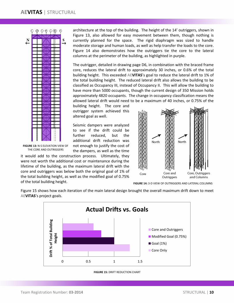
architecture at the top of the building. The height of the 14’ outriggers, shown in Figure 13, also allowed for easy movement between them, though nothing is currently planned for the space. The rigid diaphragm was sized to handle moderate storage and human loads, as well as help transfer the loads to the core. Figure 14 also demonstrates how the outriggers tie the core to the lateral columns at the perimeter of the building, as highlighted in purple.
The outrigger, detailed in drawing page D6, in combination with the braced frame core, reduces the lateral drift to approximately 30 inches, or 0.6% of the total building height. This exceeded AEVITAS’s goal to reduce the lateral drift to 1% of the total building height. The reduced lateral drift also allows the building to be classified as Occupancy III, instead of Occupancy II. This will allow the building to have more than 5000 occupants, though the current design of 350 Mission holds approximately 4820 occupants. The change in occupancy classification means the allowed lateral drift would need to be a maximum of 40 inches, or 0.75% of the building height. The core and outrigger system achieved this altered goal as well.
Seismic dampers were analyzed to see if the drift could be further reduced, but the additional drift reduction was not enough to justify the cost of the dampers, as well as the time
it would add to the construction process. Ultimately, they were not worth the additional cost or maintenance during the lifetime of the building, as the maximum lateral drift with the core and outriggers was below both the original goal of 1% of the total building height, as well as the modified goal of 0.75% of the total building height.
Figure 15 shows how each iteration of the main lateral design brought the overall maximum drift down to meet AEVITAS’s project goals.
FIGURE 15: DRIFT REDUCTION CHART
0 0.5 1 1.5
Dri
ft %
of
Tota
l Bu
ildin
g H
eig
ht
Actual Drifts vs. Goals
Core and Outriggers
Modified Goal (0.75%)
Goal (1%)
Core Only
FIGURE 13: N-S ELEVATION VIEW OF THE CORE AND OUTRIGGERS
FIGURE 14: 3-D VIEW OF OUTRIGGERS AND LATERAL COLUMNS
AEVITAS | STRUCTURAL
Team Registration Number: 03-2014 STRUCTURAL | 11
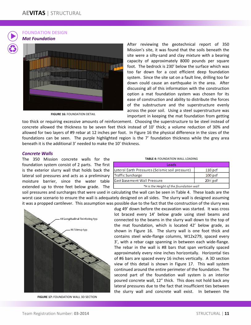
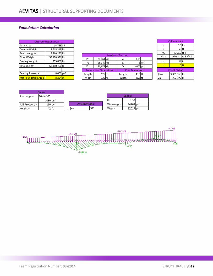
FOUNDATION DESIGN Mat Foundation
After reviewing the geotechnical report of 350 Mission’s site, it was found that the soils beneath the site were a silty-sand and clay mixture with a bearing capacity of approximately 8000 pounds per square foot. The bedrock is 230’ below the surface which was too far down for a cost efficient deep foundation system. Since the site sat on a fault line, drilling too far down could cause an earthquake in the area. After discussing all of this information with the construction option a mat foundation system was chosen for its ease of construction and ability to distribute the forces of the substructure and the superstructure evenly across the poor soil. Using a steel superstructure was important in keeping the mat foundation from getting
too thick or requiring excessive amounts of reinforcement. Choosing the superstructure to be steel instead of concrete allowed the thickness to be seven feet thick instead of 10’ thick; a volume reduction of 30% and allowed for two layers of #9 rebar at 12 inches per foot. In Figure 16 the physical difference in the sizes of the foundations can be seen. The purple highlighted region is the 7’ foundation thickness while the grey area beneath it is the additional 3’ needed to make the 10’ thickness.
Concrete Walls The 350 Mission concrete walls for the foundation system consist of 2 parts. The first is the exterior slurry wall that holds back the lateral soil pressures and acts as a preliminary moisture barrier, since the water table extended up to three feet below grade. The soil pressures and surcharges that were used in calculating the wall can be seen in Table 4. These loads are the worst case scenario to ensure the wall is adequately designed on all sides. The slurry wall is designed assuming it was a propped cantilever. This assumption was possible due to the fact that the construction of the slurry was
dug 49’ down before the excavation was started. It was cross lot braced every 14’ below grade using steel beams and connected to the beams in the slurry wall down to the top of the mat foundation, which is located 42’ below grade, as shown in Figure 16. The slurry wall is one foot thick and contains steel wide-flange columns, W12x279, spaced every 3’, with a rebar cage spanning in between each wide-flange. The rebar in the wall is #8 bars that span vertically spaced approximately every nine inches horizontally. Horizontal ties of #6 bars are spaced every 16 inches vertically. A 3D section view of this detail is shown in Figure 17. This wall system continued around the entire perimeter of the foundation. The second part of the foundation wall system is an interior poured concrete wall, 12” thick. This does not hold back any lateral pressures due to the fact that insufficient ties between the slurry wall and concrete wall exist. In between the
TABLE 4: FOUNDATION WALL LOADING
FIGURE 16: FOUNDATION DETAIL
FIGURE 17: FOUNDATION WALL 3D SECTION
AEVITAS | STRUCTURAL
Team Registration Number: 03-2014 STRUCTURAL | 12
exterior slurry wall and in the interior concrete wall is a seismically tested drainage board, to reduce the water that comes into the building if the concrete wall cracks during an earthquake. The concrete wall exists to protect the waterproofing membrane and the outer wall from accidental damage from vehicular accidents. All expansion joints between pours of the wall are also seismically detailed.
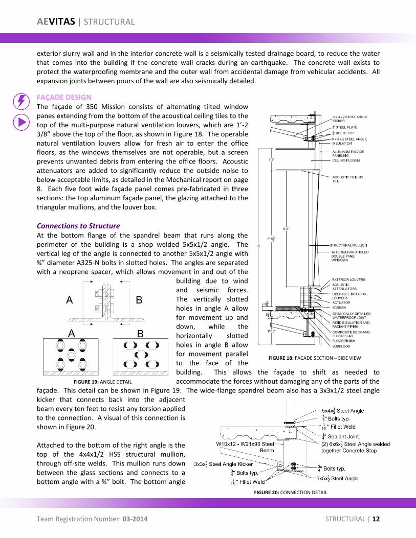
FAÇADE DESIGN The façade of 350 Mission consists of alternating tilted window panes extending from the bottom of the acoustical ceiling tiles to the top of the multi-purpose natural ventilation louvers, which are 1’-2 3/8” above the top of the floor, as shown in Figure 18. The operable natural ventilation louvers allow for fresh air to enter the office floors, as the windows themselves are not operable, but a screen prevents unwanted debris from entering the office floors. Acoustic attenuators are added to significantly reduce the outside noise to below acceptable limits, as detailed in the Mechanical report on page 8. Each five foot wide façade panel comes pre-fabricated in three sections: the top aluminum façade panel, the glazing attached to the triangular mullions, and the louver box.
Connections to Structure At the bottom flange of the spandrel beam that runs along the perimeter of the building is a shop welded 5x5x1/2 angle. The vertical leg of the angle is connected to another 5x5x1/2 angle with ¾” diameter A325-N bolts in slotted holes. The angles are separated with a neoprene spacer, which allows movement in and out of the
building due to wind and seismic forces. The vertically slotted holes in angle A allow for movement up and down, while the horizontally slotted holes in angle B allow for movement parallel to the face of the building. This allows the façade to shift as needed to accommodate the forces without damaging any of the parts of the
façade. This detail can be shown in Figure 19. The wide-flange spandrel beam also has a 3x3x1/2 steel angle kicker that connects back into the adjacent beam every ten feet to resist any torsion applied to the connection. A visual of this connection is shown in Figure 20. Attached to the bottom of the right angle is the top of the 4x4x1/2 HSS structural mullion, through off-site welds. This mullion runs down between the glass sections and connects to a bottom angle with a ¾” bolt. The bottom angle
FIGURE 18: FACADE SECTION – SIDE VIEW
FIGURE 20: CONNECTION DETAIL
FIGURE 19: ANGLE DETAIL

AEVITAS | STRUCTURAL
Team Registration Number: 03-2014 STRUCTURAL | 13
is welded to the top of the concrete stop, which is composed of two 6x6x1/2 angles welded together to form a C-shape stop at the end of the beam, as shown in Figure 20. The top section resists pullout through an embedded stud. This mullion is the primary support for the glass section of the façade. The natural ventilation louvers slide in between the mullions and are installed after the glazing is installed. The louver system connects to the structure through embedded bolts, and can be accessed through a door that allows for cleaning and repair of the louvers.
Waterproofing Due to the potential for large seismic activity during the lifetime of the building, the joint between the aluminum façade panel and the mechanical louver box is seismically detailed to prevent water from coming into the structure. This was done by placing a waterproofing membrane connected to either side of the joint, leaving extra room for movement in between the panels. At the joint face, two interlocking sides, one is a single plate, the other is a double plate, slide together. An example of this type of connection is shown in Figure 21. The width of the joint ranged between one inch during normal conditions and one and a half inches extended during an earthquake. The two panels can also move in shear in relation to one another, to a maximum displacement of two inches. The thin, flexible membrane beneath the plates can stretch and accommodate the moving façade panels during an earthquake without damaging the elements,
or allowing moisture to penetrate into the interior of the building. Since the panels were pre-fabricated, they are tested to ensure the components are waterproof. When installed on the building, waterproof testing of the structure will be done to ensure 350 Mission is properly waterproofed. This includes all joints between pre-fabricated sections and the structure.
Glazing and Mullions The glazing throughout the structure is a tilted double-paned insulating glass unit, IGU, that alternates in direction every other pane. Some are angled towards the top, and the others are angled towards the bottom to create the woven aesthetic the architect desired. Each pane of fully tempered glass is 3/8th of an inch thick, with a 3/4th of an inch air space, between them. The total IGU thickness is 1 ½”thick, and each pane is laminated for the safety and security of the spaces. This thickness allows for the differential movement of the glass due to wind, changes in temperature, or changes in barometric pressures, as well as story drifts and seismic forces. The majority of the façade is electrochromic glass, except for the mechanical rooms on the east side of every floor, the mechanical penthouse and outrigger levels at the top of the building, and the lobby at ground floor. The two different types of glazing are not detailed differently, except for the electrical connection, with wires running along the
FIGURE 21: SEISMICALLY DETAILED WATERPROOFED JOINT
FIGURE 22: FACADE SECTION AT MULLION

AEVITAS | STRUCTURAL
Team Registration Number: 03-2014 STRUCTURAL | 14
inside of the structural mullions. These wires provide electrical current to both the glass and the operable interior louvers in the natural ventilation louver box. Figure 22 shows a section of the façade cut at the mullion plane, without the natural ventilation louver box shown.
The mullions that connect to the glass are custom designed trapezoidal pieces that keep the architectural aesthetic of a woven design with the glass. The adjoining sides of the different angles of glass have a two-stage sealant process that keeps water out of the interior, even though the adjoining surface areas change along the length of the glass. A section cut of the mullion detail is shown in Figure 23. A specialty façade designer will be brought on at the beginning of the project to address specialty design issues that extend beyond the schematic design presented here. These issues include spacers between different types of metals, thermal issues, special seismic considerations, fireproofing, construction tolerances, and column shortening. Even though the custom designed and installed mullions incur higher costs and add complications to the construction to prevent waterproofing issues, it will allow 350 Mission to become an icon and a landmark in the San Francisco area. While there are cheaper versions with a decrease in aesthetics available, this design will preserve the architect’s intent for the building.
CONCLUSION AEVITAS strived to achieve the guidelines and requirements set forth by the owner to achieve a net-zero high-rise building. Through collaboration between all disciplines, AEVITAS has accomplished the goals under the overarching attitude of [ZEROimpact]. Under the [ZEROemissions] goal, the structure alone reduced emissions by 4.3% by using a steel and concrete composite structure instead of an entirely concrete structure. Additionally, all the materials used in the building came from locations as close to San Francisco, CA as possible to reduce transportation emissions. For [ZEROenergy], all energy from any earthquake is dispersed through the lateral system and does not damage any critical component of 350 Mission. Under the goal of [ZEROwaste], all connections that can are made off-site, which saves wasted material and time. All beams, girders, and decking are sized to provide the necessary support, but without unnecessary steel or concrete. Under [ZEROinterruption], the overall drift of the building is limited to 0.6% of the total building height, which is less than half of what code allows in a more stringent occupancy classification than what is bare code minimum and 0.4% less than what was required. The structure minimally interrupts the occupants as well as the neighboring community, with no noticeable vibrations, and as least-invasive construction as possible. Each of these goals contributed to the required goals set forth at the beginning of the competition. These requirements were 1% of the total building height for drift, and a net-zero high-rise.
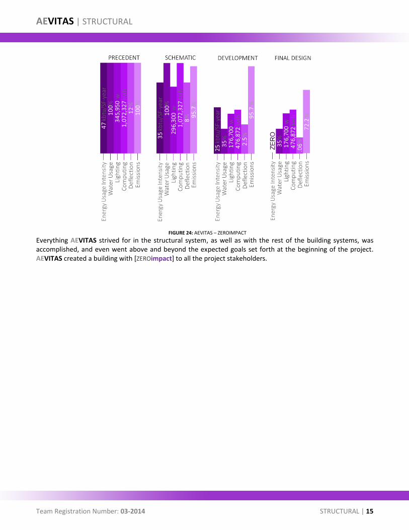
Many different designs were considered, and many options were analyzed to come up with the best solution to fit the goals and attitude of AEVITAS. All disciplines worked together and contributed to the design to bring 350 Mission down to net-zero. Figure 24 shows a graphical breakdown of how AEVITAS reduces different elements to hit the goals. The precedent section is an equalized baseline for comparison. Throughout the design of the building, all disciplines contributed to reducing the numbers as low as possible, and making up the rest by contributing energy back into the grid. Certain bars could not reach zero, for example the emissions bar, since AEVITAS considers emissions produced by transportation equipment, manufacturing process, and natural emissions of materials. However, AEVITAS acknowledges these limitations and works to give back to the environment in other ways.
FIGURE 23: MULLION DETAIL SECTION A-A FROM FIGURE 22 - NTS
AEVITAS | STRUCTURAL
Team Registration Number: 03-2014 STRUCTURAL | 15
Everything AEVITAS strived for in the structural system, as well as with the rest of the building systems, was accomplished, and even went above and beyond the expected goals set forth at the beginning of the project. AEVITAS created a building with [ZEROimpact] to all the project stakeholders.
FIGURE 24: AEVITAS – ZEROIMPACT

AEVITAS | STRUCTURAL SUPPORTING DOCUMENTS
Team Registration Number: 03-2014 STRUCTURAL | SD1
DETAILS
Façade Sections
AEVITAS | STRUCTURAL SUPPORTING DOCUMENTS
Team Registration Number: 03-2014 STRUCTURAL | SD2
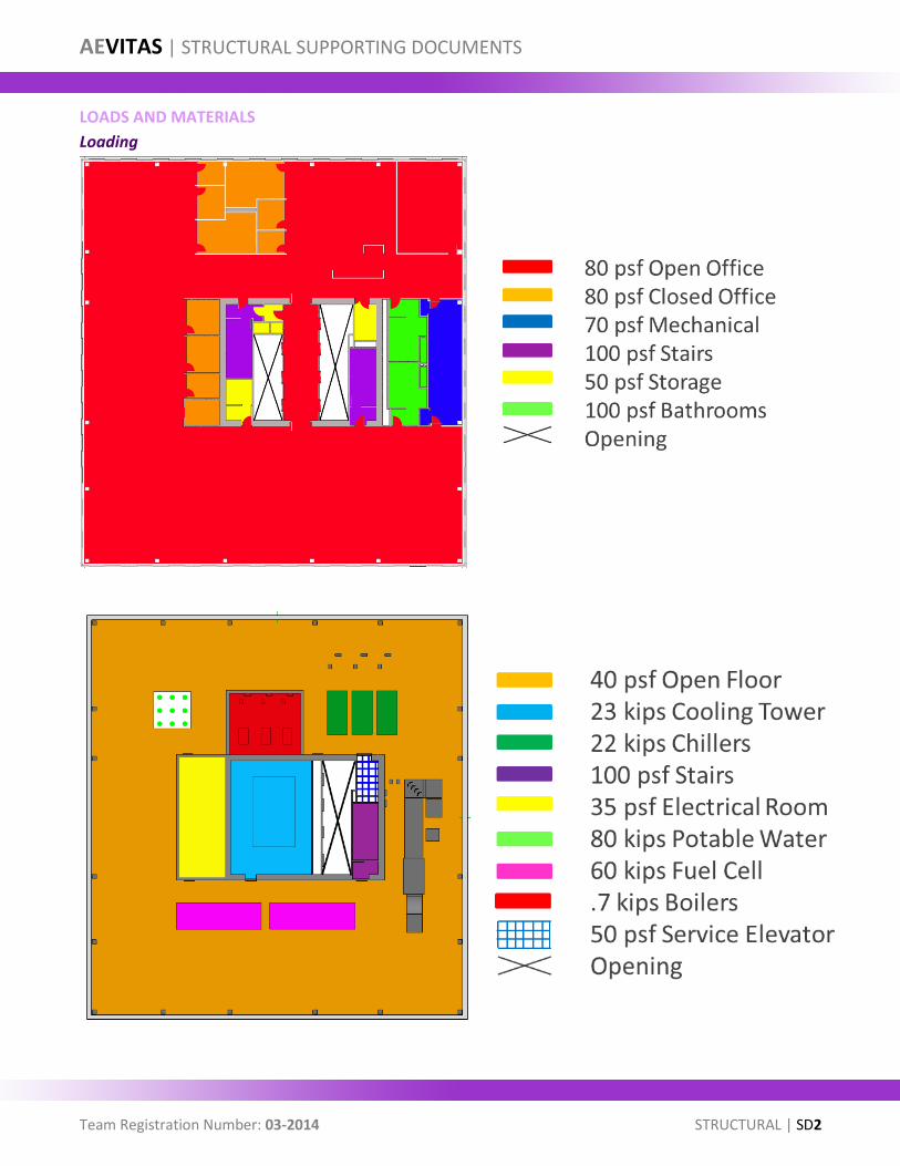
LOADS AND MATERIALS
Loading
80 psf Open Office
80 psf Closed Office
70 psf Mechanical 100 psf Stairs
50 psf Storage
100 psf Bathrooms
Opening

AEVITAS | STRUCTURAL SUPPORTING DOCUMENTS
Team Registration Number: 03-2014 STRUCTURAL | SD3
Materials Used
Material Type Specific Usage Size Range
Steel
Wide-Flange
Beams W8x10 W21x132
Girders W18x35 W30x90
Columns W14x43 W14x730
HSS Shapes Bracing HSS3x3x3/16 HSS10x10x5/8
Steel Plates
Gusset Plates 1/2" 1"
Stiffener Plates 1/2"
Connection Plates 1/2"
Angles
Connections ⏌⎿ 5x5x1/2
Torsional Kickers ⏌3x3x1/2
Concrete Stops ⏌6x6x1/2
Bolts
3/4" ø A325-N
Shear Studs
5"
Reinforcement
Longitudinal #7 #8
Ties #4 #6
Mesh #3
Decking
19 Gage
Concrete
Below-Grade
11" thick 7' thick
Above-Grade Slab
6 1/2"
Columns
4' square
Wide Flange Beams and Girders
Wide Flange Columns
Square HSS Bracing
Double Angles Connections
Single Angle Kickers and Stops
A325-N Structural Bolts Shear Studs
Rebar
AEVITAS | STRUCTURAL SUPPORTING DOCUMENTS
Team Registration Number: 03-2014 STRUCTURAL | SD4
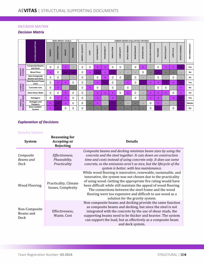
DECISION MATRIX
Decision Matrix
Explanation of Decisions
Gravity System
System Reasoning for Accepting or
Rejecting Details
Composite Beams and Deck
Effectiveness, Phaseabilty, Practicality
Composite beams and decking minimize beam sizes by using the concrete and the steel together. It cuts down on construction
time and costs instead of using concrete only. It does use some concrete, so the emissions aren’t as nice, but the lifecycle of the
system is better, with less maintenance.
Wood Flooring Practicality, Climate Issues, Complexity
While wood flooring is innovative, renewable, sustainable, and innovative, the system was not chosen due to the practicality of using wood. Getting the appropriate fire rating would have been difficult while still maintain the appeal of wood flooring.
The connections between the steel frame and the wood flooring were too expensive and difficult to use wood as a
solution for the gravity system.
Non-Composite Beams and Deck
Effectiveness, Waste, Cost
Non-composite beams and decking provide the same function as composite beams and decking, but since the steel is not integrated with the concrete by the use of shear studs, the
supporting beams need to be thicker and heavier. The system can support the load, but as effectively as a composite beam
and deck system.
EN
ER
GY
INT
ER
RU
PT
ION
WA
ST
E
EM
ISS
ION
S
EN
ER
GY
QU
AN
TIT
Y
CO
ST
SU
ST
AIN
AB
ILIT
Y
PH
AS
EA
BIL
ITY
INN
OV
AT
ION
CO
MP
LE
XIT
Y
SP
AC
E N
EE
DE
D
MA
INT
EN
AN
CE
INT
EG
RA
TIO
N
SIT
E/C
LIM
AT
E IS
SU
ES
TE
AC
HIN
G
PR
AC
TIC
AL
ITY
LIF
EC
YC
LE
EF
FE
CT
IVE
NE
SS
Composite Beams
and Deck 0 0 + - 0 0 + + 0 0 - 0 + - 0 + + ++ Yes
Wood Floor + 0 ++ ++ 0 + ++ + ++ - - - 0 -- ++ -- -- - No
Non-Composite
Beams and Deck 0 0 - - 0 - 0 + 0 0 -- 0 - - 0 - 0 - No
Steel Braced Frame
Core 0 + + 0 0 - + ++ 0 - + 0 ++ + + ++ + ++ Yes
Concrete Core 0 + - -- 0 + 0 - 0 - 0 - - - 0 0 - + No
Steel Shear Walls 0 0 + 0 0 - + + + 0 + 0 - + + + 0 + No
Outriggers 0 + + 0 0 - + - + -- - 0 - + + - + ++ Yes
Outrigger and
Dampers + ++ + 0 0 -- + - ++ -- - -- - 0 + - - ++ Maybe
Base Isolation
System + ++ 0 0 0 -- -- -- ++ -- -- -- -- 0 ++ - 0 ++ No
RE
CO
MM
EN
DE
D?
GR
AV
ITY
SY
ST
EM
LA
TE
RA
L
SY
ST
EM
SP
EC
IAL
SE
ISM
IC D
ES
IGN
ZERO IMPACT GOALS OWNER DRIVEN EVALUATION CRITERIA
SY
ST
EM
DE
SC
RIP
TIO
N
AEVITAS | STRUCTURAL SUPPORTING DOCUMENTS
Team Registration Number: 03-2014 STRUCTURAL | SD5
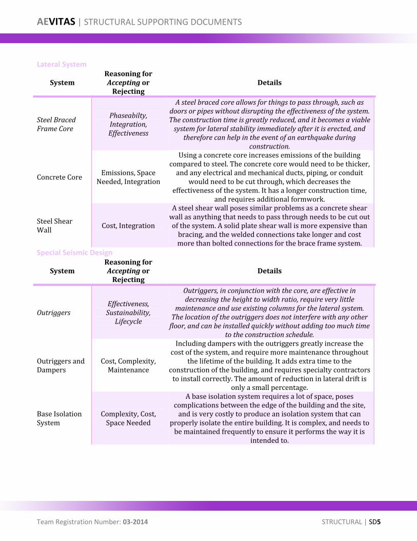
Lateral System
System Reasoning for Accepting or
Rejecting Details
Steel Braced Frame Core
Phaseabilty, Integration, Effectiveness
A steel braced core allows for things to pass through, such as doors or pipes without disrupting the effectiveness of the system. The construction time is greatly reduced, and it becomes a viable
system for lateral stability immediately after it is erected, and therefore can help in the event of an earthquake during
construction.
Concrete Core Emissions, Space
Needed, Integration
Using a concrete core increases emissions of the building compared to steel. The concrete core would need to be thicker,
and any electrical and mechanical ducts, piping, or conduit would need to be cut through, which decreases the
effectiveness of the system. It has a longer construction time, and requires additional formwork.
Steel Shear Wall
Cost, Integration
A steel shear wall poses similar problems as a concrete shear wall as anything that needs to pass through needs to be cut out of the system. A solid plate shear wall is more expensive than
bracing, and the welded connections take longer and cost more than bolted connections for the brace frame system.
Special Seismic Design
System Reasoning for Accepting or
Rejecting Details
Outriggers Effectiveness, Sustainability,
Lifecycle
Outriggers, in conjunction with the core, are effective in decreasing the height to width ratio, require very little
maintenance and use existing columns for the lateral system. The location of the outriggers does not interfere with any other
floor, and can be installed quickly without adding too much time to the construction schedule.
Outriggers and Dampers
Cost, Complexity, Maintenance
Including dampers with the outriggers greatly increase the cost of the system, and require more maintenance throughout
the lifetime of the building. It adds extra time to the construction of the building, and requires specialty contractors
to install correctly. The amount of reduction in lateral drift is only a small percentage.
Base Isolation System
Complexity, Cost, Space Needed
A base isolation system requires a lot of space, poses complications between the edge of the building and the site,
and is very costly to produce an isolation system that can properly isolate the entire building. It is complex, and needs to
be maintained frequently to ensure it performs the way it is intended to.
AEVITAS | STRUCTURAL SUPPORTING DOCUMENTS
Team Registration Number: 03-2014 STRUCTURAL | SD6
SAMPLE CALCULATIONS Wind Load Preliminary Calculations

AEVITAS | STRUCTURAL SUPPORTING DOCUMENTS
Team Registration Number: 03-2014 STRUCTURAL | SD7
AEVITAS | STRUCTURAL SUPPORTING DOCUMENTS
Team Registration Number: 03-2014 STRUCTURAL | SD8
Seismic Load Preliminary Calculations
AEVITAS | STRUCTURAL SUPPORTING DOCUMENTS
Team Registration Number: 03-2014 STRUCTURAL | SD9
Typical Office Floor Load Calculations
AEVITAS | STRUCTURAL SUPPORTING DOCUMENTS
Team Registration Number: 03-2014 STRUCTURAL | SD10
Typical Column Calculation
Dead Load (psf) Live Load (psf) Total Load (psf)
15 20 50
Dead Load (psf) Live Load (psf) Total Load (psf)
20 50 104
Dead Load (psf) Live Load (psf) Total Load (psf)
18 80 149.6
Roof Loads
Mechanical Loads
Typical Floor Load
Length 11.1 ft
Width 13.8 ft
Tributary Area 153.4 ft2
Pu 230.1 kips
Corner Column (A6-Level 20) W14X68
AEVITAS | STRUCTURAL SUPPORTING DOCUMENTS
Team Registration Number: 03-2014 STRUCTURAL | SD11
Concrete Encased Wide-Flange Calculation
Typical Brace Calculation
K 1
Lx 28 ft
rx 2.41 in
Fy 60 ksi
Fe 26.7 ksi
E 29000 ksi
KLx/rx 139.4
4.71√(E/Fy) 103.5
KLx/rx > 4.71√(E/Fy) OK
Checks
Fcr 23.4 ksi
Ag 20 in2
φ 0.9
φPn=FcrAg 421.6 kips
OKφPn > Pu
Allowable Load for W14x68
Pu = φcPn
Pn = AsFcr
λc = c1 0.7
Fmy = c2 0.6
Em = c3 0.2
φc 0.85 Ar 5.28 sq. in
Fy 50 ksi As 215 sq. in
Fyr 60 ksi Ac 2084 sq. in
f'c 5 ksi E 29000 ksi
Fmy 80.11 ksi
Em 36813 ksi
λc 0.825 ≤ 1.5 ok
Fcr 35.86
φPn 6553 kips >6210 kips ok
(required axial strength)
(nominal axial strenth)
4'x4' Column W14x730 (12) #6's longitudinal reinforcement
Use 4'x4' Concrete Columns with W14x730, (12) #7's and f'c = 5ksi, Shear
studs and ties spaced every 12"
Fy + c1Fyr(Ar/As) + c2f'c(Ac/As)
(Kl/rmπ)√(Fmy/Em)
E + c3Ec(Ac/As)
Design of Composite Columns for the Lobby - Typical
AEVITAS | STRUCTURAL SUPPORTING DOCUMENTS
Team Registration Number: 03-2014 STRUCTURAL | SD12
Foundation Calculation
Total Area 14,765 SF
Column Weights 2,915,319 lb
Beam Weights 3,760,290 lb
Floor Weight 59,178,931 lb
Bracing Weight 255,860 lb
Total Weight 66,110,400 lb
Bearing Pressure 8,000 psf
Mat Foundation Area 8,264 sf
Mat Foundation Area
PD 37,761 kip φ 0.55
PL 28,349 kip qu 8 ksf
PU 90,672 kip f'c 4000 psi
Length 125 ft Length 48.5 ft
Width 125 ft Width 48.5 ft
Loads and Factors
Foundation Dimensions Core Dimensions
q 5.8 ksf
L 50 ft
Mu 7363.0 ft-k
Mu ≤ φMn = φ 5 √f'c S
h 72 in
h 6 ft
φVn 3,339,365 lb
Vu 292,327 lb
Check Shear
Calculations
Surcharge = 20H + 100
1080 psf
Soil Pressure = 110 pcf
Height = 42 ft
Given:
φ = 30°
Assumptions:Ka 0.33
Wsurcharge = 14969 plf
Wsoil = 32017 plf
Loads:
AEVITAS | STRUCTURAL SUPPORTING DOCUMENTS
Team Registration Number: 03-2014 STRUCTURAL | SD13
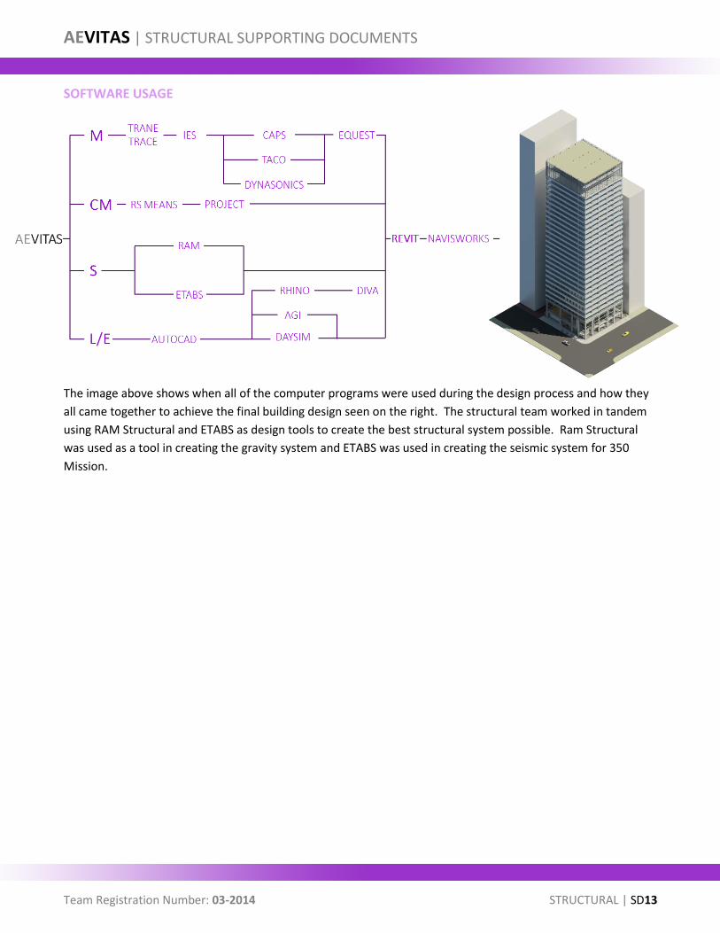
SOFTWARE USAGE
The image above shows when all of the computer programs were used during the design process and how they
all came together to achieve the final building design seen on the right. The structural team worked in tandem
using RAM Structural and ETABS as design tools to create the best structural system possible. Ram Structural
was used as a tool in creating the gravity system and ETABS was used in creating the seismic system for 350
Mission.
AEVITAS | STRUCTURAL SUPPORTING DOCUMENTS
Team Registration Number: 03-2014 STRUCTURAL | SD14
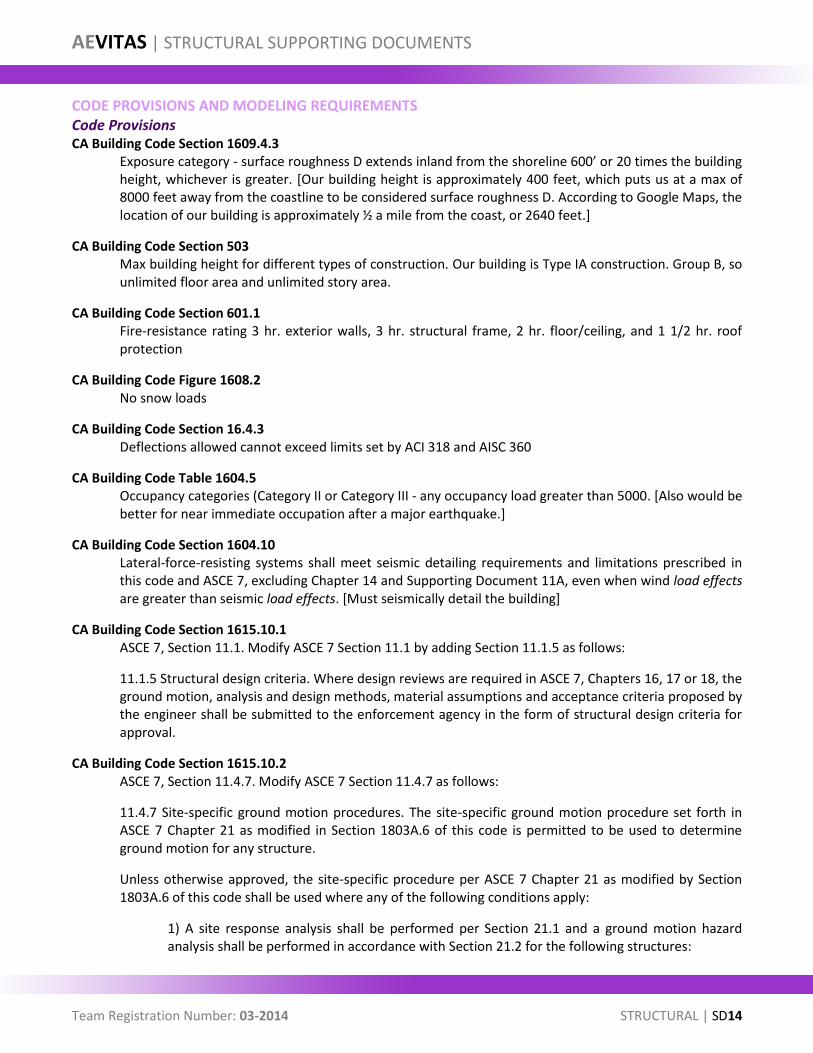
CODE PROVISIONS AND MODELING REQUIREMENTS Code Provisions CA Building Code Section 1609.4.3
Exposure category - surface roughness D extends inland from the shoreline 600’ or 20 times the building height, whichever is greater. [Our building height is approximately 400 feet, which puts us at a max of 8000 feet away from the coastline to be considered surface roughness D. According to Google Maps, the location of our building is approximately ½ a mile from the coast, or 2640 feet.]
CA Building Code Section 503 Max building height for different types of construction. Our building is Type IA construction. Group B, so unlimited floor area and unlimited story area.
CA Building Code Section 601.1 Fire-resistance rating 3 hr. exterior walls, 3 hr. structural frame, 2 hr. floor/ceiling, and 1 1/2 hr. roof protection
CA Building Code Figure 1608.2 No snow loads
CA Building Code Section 16.4.3 Deflections allowed cannot exceed limits set by ACI 318 and AISC 360
CA Building Code Table 1604.5 Occupancy categories (Category II or Category III - any occupancy load greater than 5000. [Also would be better for near immediate occupation after a major earthquake.]
CA Building Code Section 1604.10 Lateral-force-resisting systems shall meet seismic detailing requirements and limitations prescribed in this code and ASCE 7, excluding Chapter 14 and Supporting Document 11A, even when wind load effects are greater than seismic load effects. [Must seismically detail the building]
CA Building Code Section 1615.10.1 ASCE 7, Section 11.1. Modify ASCE 7 Section 11.1 by adding Section 11.1.5 as follows:
11.1.5 Structural design criteria. Where design reviews are required in ASCE 7, Chapters 16, 17 or 18, the ground motion, analysis and design methods, material assumptions and acceptance criteria proposed by the engineer shall be submitted to the enforcement agency in the form of structural design criteria for approval.
CA Building Code Section 1615.10.2 ASCE 7, Section 11.4.7. Modify ASCE 7 Section 11.4.7 as follows:
11.4.7 Site-specific ground motion procedures. The site-specific ground motion procedure set forth in ASCE 7 Chapter 21 as modified in Section 1803A.6 of this code is permitted to be used to determine ground motion for any structure.
Unless otherwise approved, the site-specific procedure per ASCE 7 Chapter 21 as modified by Section 1803A.6 of this code shall be used where any of the following conditions apply:
1) A site response analysis shall be performed per Section 21.1 and a ground motion hazard analysis shall be performed in accordance with Section 21.2 for the following structures:

AEVITAS | STRUCTURAL SUPPORTING DOCUMENTS
Team Registration Number: 03-2014 STRUCTURAL | SD15
a) Structure located in Type E soils and mapped MCE spectral acceleration at short periods (Ss) exceeds 2.0g.
b) Structures located in Type F soils.
Exception:
1) Where Ss is less than 0.20g, use of Type E soil profile shall be permitted.
2) Where exception to Section 20.3.1 is applicable except for base isolated buildings.
2) A ground motion hazard analysis shall be performed in accordance with Section 21.2 when:
a) A time history response analysis of the building is performed as part of the design.
b) The building site is located in an area identified in Section 4-317(e) of the California Administrative Code (Part 1, Title 24, C.C.R).
c) For seismically isolated structures and for structures with damping systems.
CA Building Code Section 1615.7.2 Story drift for wind loads. The calculated story drift due to wind pressures shall not exceed 0.005 times the story height for buildings less than 65 feet (19 812 mm) in height or 0.004 times the story height for buildings 65 feet (19 812 mm) or greater in height.
ASCE 7-10 Table 12.12-1 Allowable Story Drift table for different risk categories
Modeling Requirements ASCE 7 12.1.1
Basic Requirements. …An approved alternative procedure shall not be used to establish the seismic forces and their distribution unless the corresponding internal forces and deformations in the members are determined using a model consistent with the procedure adopted.
San Francisco Building Code sections that discuss non-prescriptive or “alternative” seismic design procedures are reproduced below:
104A.2.8 Alternate materials, design and methods of construction. The provisions of this code are not intended to prevent the use of any material, alternate design or method of construction not specifically prescribed by this code, provided any alternate has been approved and its use authorized by the building official. The building official may approve any such alternate, provided the building official finds that the proposed design is satisfactory and complies with the provisions of this code and that the material, method or work offered is, for the purpose intended, at least the equivalent of that prescribed in this code in suitability, strength, effectiveness, fire resistance, durability, safety and sanitation.
The building official shall require that sufficient evidence or proof be submitted to substantiate any claims that may be made regarding its use. The details of any action granting approval of an alternate shall be recorded and entered in the files of the code enforcement agency.
AEVITAS | STRUCTURAL SUPPORTING DOCUMENTS
Team Registration Number: 03-2014 STRUCTURAL | SD16
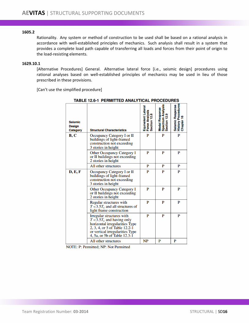
1605.2 Rationality. Any system or method of construction to be used shall be based on a rational analysis in accordance with well-established principles of mechanics. Such analysis shall result in a system that provides a complete load path capable of transferring all loads and forces from their point of origin to the load-resisting elements.
1629.10.1 [Alternative Procedures] General. Alternative lateral force [i.e., seismic design] procedures using rational analyses based on well-established principles of mechanics may be used in lieu of those prescribed in these provisions.
[Can’t use the simplified procedure]
AEVITAS | STRUCTURAL SUPPORTING DOCUMENTS
Team Registration Number: 03-2014 STRUCTURAL | SD17
GEOTECHNICAL INFORMATION
The foundation walls were designed with the pressures in the above tables. The lateral earth pressure used for
the restrained wall condition was 110 pounds per cubic foot with the addition of the 100 pounds per square foot
traffic load surcharge and the 20H east basement wall pressure. This was assumed to be the worst case scenario
and was applied to all walls to ensure the size of the foundation wall was adequate.
AEVITAS | STRUCTURAL SUPPORTING DOCUMENTS
Team Registration Number: 03-2014 STRUCTURAL | SD18
LEED CHECKLIST
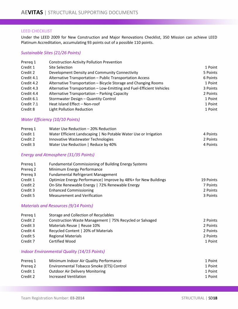
Under the LEED 2009 for New Construction and Major Renovations Checklist, 350 Mission can achieve LEED Platinum Accreditation, accumulating 93 points out of a possible 110 points.
Sustainable Sites (21/26 Points)
Prereq 1 Construction Activity Pollution Prevention Credit 1 Site Selection 1 Point Credit 2 Development Density and Community Connectivity 5 Points Credit 4.1 Alternative Transportation – Public Transportation Access 6 Points Credit 4.2 Alternative Transportation – Bicycle Storage and Changing Rooms 1 Point Credit 4.3 Alternative Transportation – Low-Emitting and Fuel-Efficient Vehicles 3 Points Credit 4.4 Alternative Transportation – Parking Capacity 2 Points Credit 6.1 Stormwater Design – Quantity Control 1 Point Credit 7.1 Heat Island Effect – Non-roof 1 Point Credit 8 Light Pollution Reduction 1 Point
Water Efficiency (10/10 Points)
Prereq 1 Water Use Reduction – 20% Reduction Credit 1 Water Efficient Landscaping | No Potable Water Use or Irrigation 4 Points Credit 2 Innovative Wastewater Technologies 2 Points Credit 3 Water Use Reduction | Reduce by 40% 4 Points
Energy and Atmosphere (31/35 Points)
Prereq 1 Fundamental Commissioning of Building Energy Systems Prereq 2 Minimum Energy Performance Prereq 3 Fundamental Refrigerant Management Credit 1 Optimize Energy Performance| Improve by 48%+ for New Buildings 19 Points Credit 2 On-Site Renewable Energy | 72% Renewable Energy 7 Points Credit 3 Enhanced Commissioning 2 Points Credit 5 Measurement and Verification 3 Points
Materials and Resources (9/14 Points)
Prereq 1 Storage and Collection of Recyclables Credit 2 Construction Waste Management | 75% Recycled or Salvaged 2 Points Credit 3 Materials Reuse | Reuse 10% 2 Points Credit 4 Recycled Content | 20% of Materials 2 Points Credit 5 Regional Materials 2 Points Credit 7 Certified Wood 1 Point
Indoor Environmental Quality (14/15 Points)
Prereq 1 Minimum Indoor Air Quality Performance 1 Point Prereq 2 Environmental Tobacco Smoke (ETS) Control 1 Point Credit 1 Outdoor Air Delivery Monitoring 1 Point Credit 2 Increased Ventilation 1 Point
AEVITAS | STRUCTURAL SUPPORTING DOCUMENTS
Team Registration Number: 03-2014 STRUCTURAL | SD19
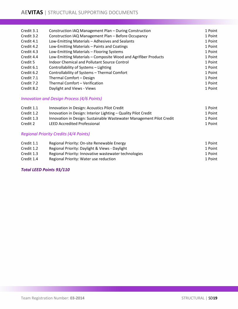
Credit 3 .1 Construction IAQ Management Plan – During Construction 1 Point Credit 3.2 Construction IAQ Management Plan – Before Occupancy 1 Point Credit 4.1 Low-Emitting Materials – Adhesives and Sealants 1 Point Credit 4.2 Low-Emitting Materials – Paints and Coatings 1 Point Credit 4.3 Low-Emitting Materials – Flooring Systems 1 Point Credit 4.4 Low-Emitting Materials – Composite Wood and Agrifiber Products 1 Point Credit 5 Indoor Chemical and Pollutant Source Control 1 Point Credit 6.1 Controllability of Systems – Lighting 1 Point Credit 6.2 Controllability of Systems – Thermal Comfort 1 Point Credit 7.1 Thermal Comfort – Design 1 Point Credit 7.2 Thermal Comfort – Verification 1 Point Credit 8.2 Daylight and Views - Views 1 Point
Innovation and Design Process (4/6 Points)
Credit 1.1 Innovation in Design: Acoustics Pilot Credit 1 Point Credit 1.2 Innovation in Design: Interior Lighting – Quality Pilot Credit 1 Point Credit 1.3 Innovation in Design: Sustainable Wastewater Management Pilot Credit 1 Point Credit 2 LEED Accredited Professional 1 Point
Regional Priority Credits (4/4 Points)
Credit 1.1 Regional Priority: On-site Renewable Energy 1 Point Credit 1.2 Regional Priority: Daylight & Views - Daylight 1 Point Credit 1.3 Regional Priority: Innovative wastewater technologies 1 Point Credit 1.4 Regional Priority: Water use reduction 1 Point
Total LEED Points 93/110
AEVITAS | STRUCTURAL SUPPORTING DOCUMENTS
Team Registration Number: 03-2014 STRUCTURAL | SD20
REFERENCES
Ali, Mir, and Kyoung Sun Moon. "Structural Developments in Tall Buildings: Current Trends and Future Prospects." Architectural Science Review 50, no. 3 (2007): 205-223.
Baker, Clyde N. “Uncertain Geotechnical Truth and Cost Effective High-Rise Foundation Design.” ASCE (2010): 1-43
Bowland, Adam. “Comparison and Analysis of the Strength, Stiffness, and Damping Characteristics of Concrete with Rubber, Latex, and Carbonate Additives.” PhD diss., University of Virginia Polytechnic Institute and State University, 2011.
Brandow, Greg, and Lawrence Brugger. An Alternative Procedure for Seismic Analysis and Design of Tall Buildings Located in the Los Angeles Region. Los Angeles: LATBSDC, 2011.
Buchanan, Andrew, Des Bull, and Rajesh Dhakal. "Base Isolation and Damping Devices." In Base Isolation and Damage-Resistant Technologies for Improved Seismic Performance of Buildings. Christchurch, New Zeland: University of Canterbury, 2011. 18-28.
Building Code Requirements for Structural Concrete (ACI 318-11) and Commentary. Farmington Hills, MI: American Concrete Institute, 2011.
Das, Braja M.. Principles of foundation engineering. 7th ed. Stanford, CT: Cengage Learning, 2011.
Halis Gunel, M., and H. Emre Ilgin. "A Proposal for the Classification of Structural Systems of Tall Builings." Building and Environment 42, no. 7 (2007): 2667-2675. http://www.sciencedirect.com/science/article/pii/S0360132306001855 (accessed October 10, 2013).
Leet, Kenneth, and Chia Uang. Fundamentals of structural analysis. 3rd ed. Boston: McGraw-Hill Higher Education, 2008.
Minimum Design Loads for Buildings and Other Structures. Reston, Va.: American Society of Civil Engineers/Structural Engineering Institute, 2006.
Moehle, J. P. (2006), Seismic analysis, design, and review for tall buildings. Struct. Design Tall Spec. Build., 15: 495–513. doi: 10.1002/tal.378
Nair, Shankar. "Belt Trusses and Basements as "Virtual" Outriggers for Tall Buildings." Engineering Journal 4 Qtr (1998): 140-146.
Seismic Design Manual. 2nd ed. Chicago: American Institute of Steel Construction, 2012.
Steel Construction Manual. 14th ed. Chicago, Ill.: American Institute of Steel Construction, 2011.
Tsai, C.S. “Applications of Viscoelastic Dampers to High-Rise Buildings.” J. Structural Engineering 119 (1993): 1222-1233
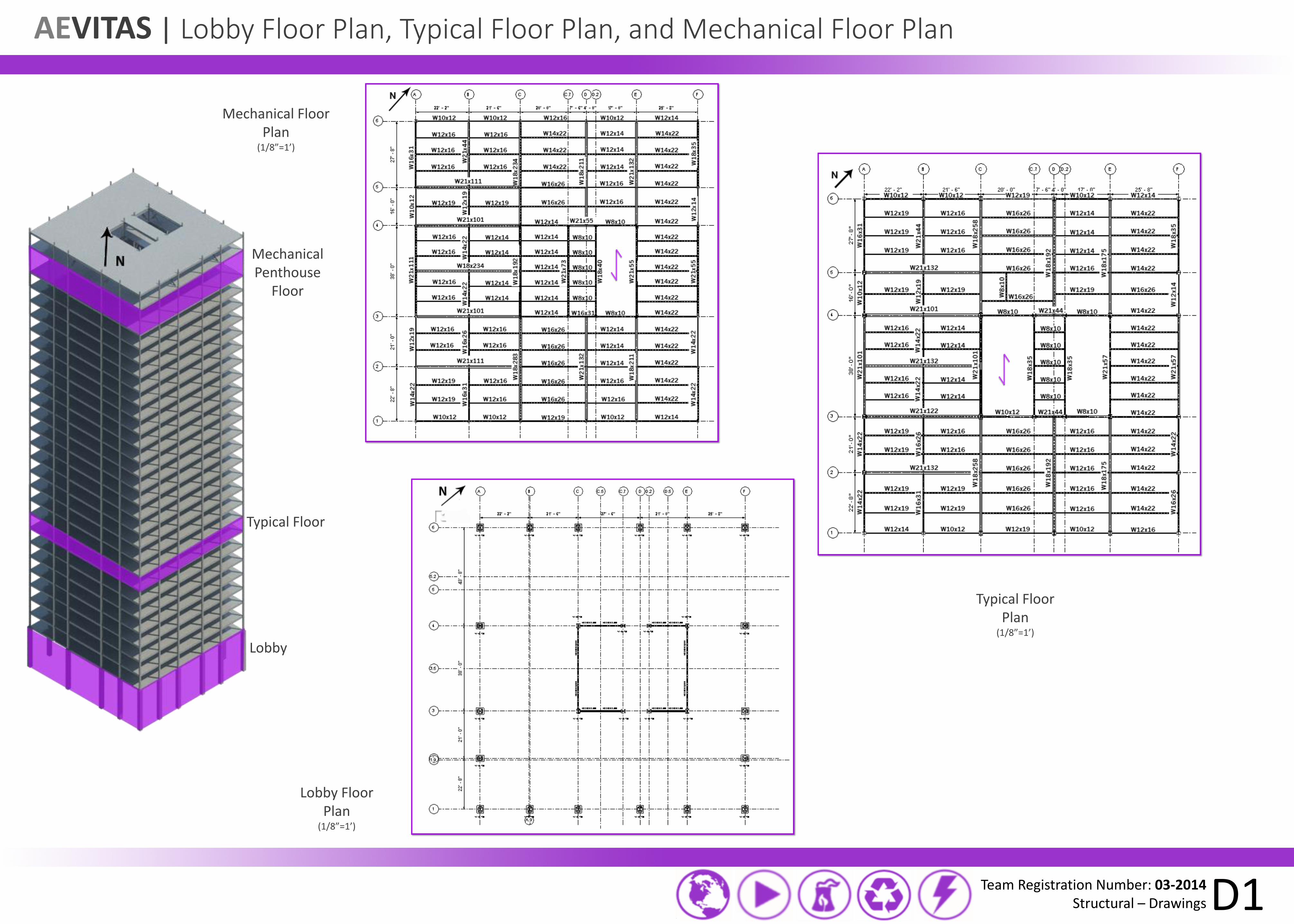
AEVITAS | Lobby Floor Plan, Typical Floor Plan, and Mechanical Floor Plan
Team Registration Number: 03-2014 Structural – Drawings D1
Typical Floor Plan
(1/8”=1’)
Lobby Floor Plan
(1/8”=1’)
Mechanical Floor Plan
(1/8”=1’)
Mechanical Penthouse
Floor
Typical Floor
Lobby
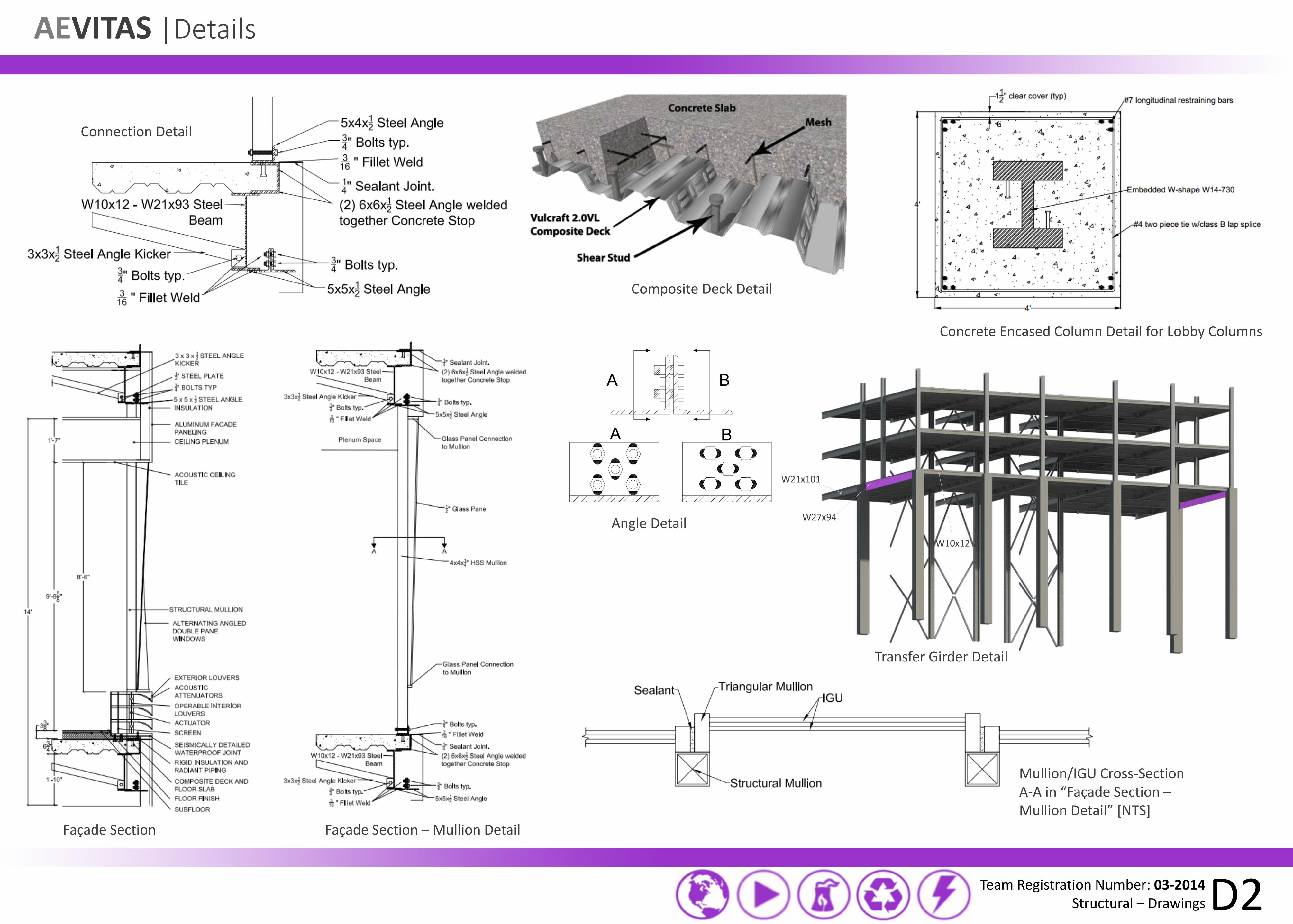
AEVITAS |Details
Team Registration Number: 03-2014 Structural – Drawings D2
Composite Deck Detail
Connection Detail
Concrete Encased Column Detail for Lobby Columns
Transfer Girder Detail
W27x94
W21x101
W10x12
Façade Section – Mullion Detail Façade Section
Angle Detail
Mullion/IGU Cross-Section A-A in “Façade Section – Mullion Detail” [NTS]
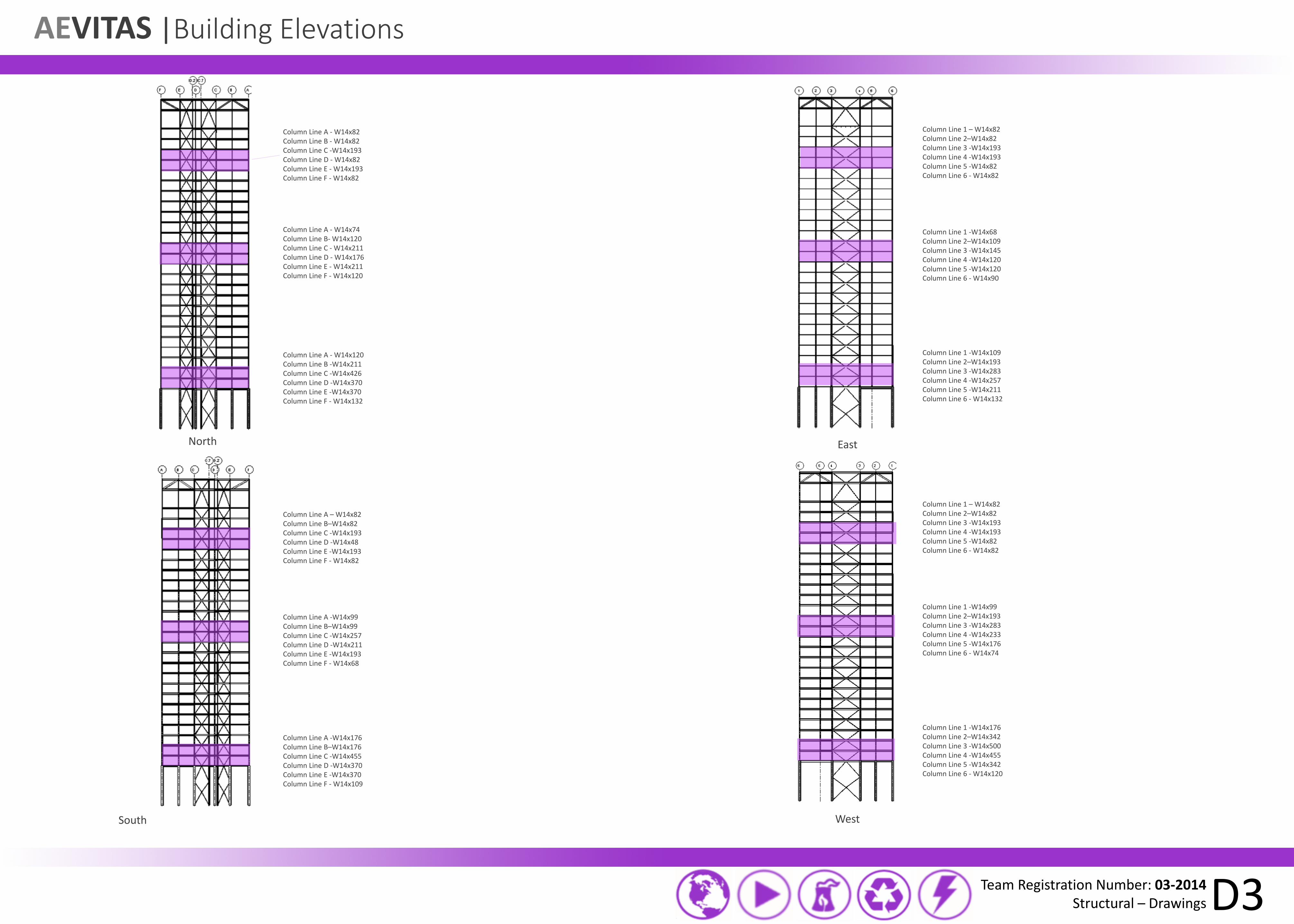
AEVITAS |Building Elevations
Team Registration Number: 03-2014 Structural – Drawings D3
North
South
East
West
Column Line A - W14x120 Column Line B -W14x211 Column Line C -W14x426 Column Line D -W14x370 Column Line E -W14x370 Column Line F - W14x132
Column Line A - W14x74 Column Line B- W14x120 Column Line C - W14x211 Column Line D - W14x176 Column Line E - W14x211 Column Line F - W14x120
Column Line A - W14x82 Column Line B - W14x82 Column Line C -W14x193 Column Line D - W14x82 Column Line E - W14x193 Column Line F - W14x82
Column Line A – W14x82 Column Line B–W14x82 Column Line C -W14x193 Column Line D -W14x48 Column Line E -W14x193 Column Line F - W14x82
Column Line A -W14x99 Column Line B–W14x99 Column Line C -W14x257 Column Line D -W14x211 Column Line E -W14x193 Column Line F - W14x68
Column Line A -W14x176 Column Line B–W14x176 Column Line C -W14x455 Column Line D -W14x370 Column Line E -W14x370 Column Line F - W14x109
Column Line 1 – W14x82 Column Line 2–W14x82 Column Line 3 -W14x193 Column Line 4 -W14x193 Column Line 5 -W14x82 Column Line 6 - W14x82
Column Line 1 -W14x68 Column Line 2–W14x109 Column Line 3 -W14x145 Column Line 4 -W14x120 Column Line 5 -W14x120 Column Line 6 - W14x90
Column Line 1 -W14x109 Column Line 2–W14x193 Column Line 3 -W14x283 Column Line 4 -W14x257 Column Line 5 -W14x211 Column Line 6 - W14x132
Column Line 1 – W14x82 Column Line 2–W14x82 Column Line 3 -W14x193 Column Line 4 -W14x193 Column Line 5 -W14x82 Column Line 6 - W14x82
Column Line 1 -W14x99 Column Line 2–W14x193 Column Line 3 -W14x283 Column Line 4 -W14x233 Column Line 5 -W14x176 Column Line 6 - W14x74
Column Line 1 -W14x176 Column Line 2–W14x342 Column Line 3 -W14x500 Column Line 4 -W14x455 Column Line 5 -W14x342 Column Line 6 - W14x120
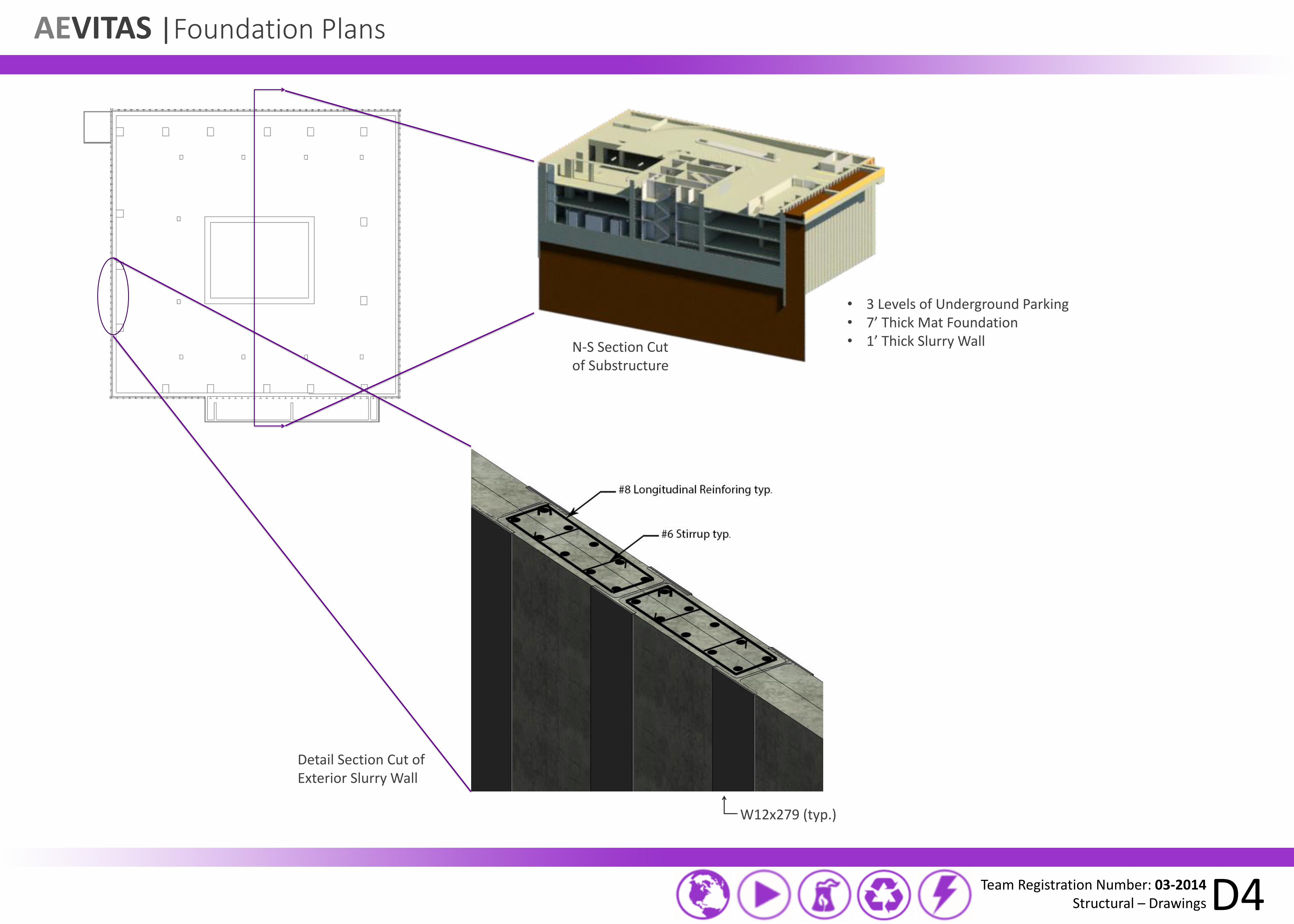
AEVITAS |Foundation Plans
Team Registration Number: 03-2014 Structural – Drawings D4
N-S Section Cut of Substructure
Detail Section Cut of Exterior Slurry Wall
W12x279 (typ.)
• 3 Levels of Underground Parking • 7’ Thick Mat Foundation • 1’ Thick Slurry Wall
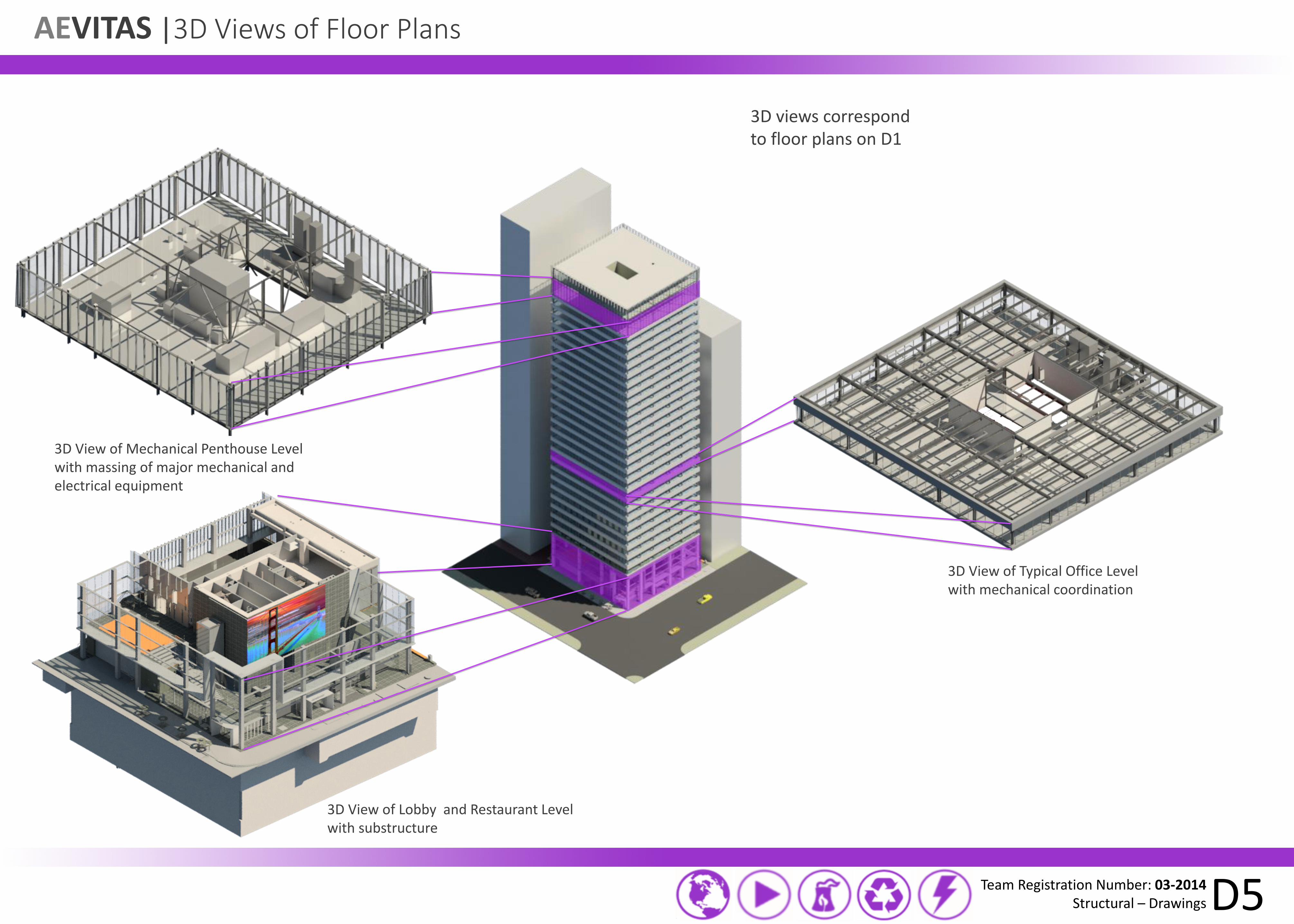
AEVITAS |3D Views of Floor Plans
Team Registration Number: 03-2014 Structural – Drawings D5
3D views correspond to floor plans on D1
3D View of Typical Office Level with mechanical coordination
3D View of Mechanical Penthouse Level with massing of major mechanical and electrical equipment
3D View of Lobby and Restaurant Level with substructure
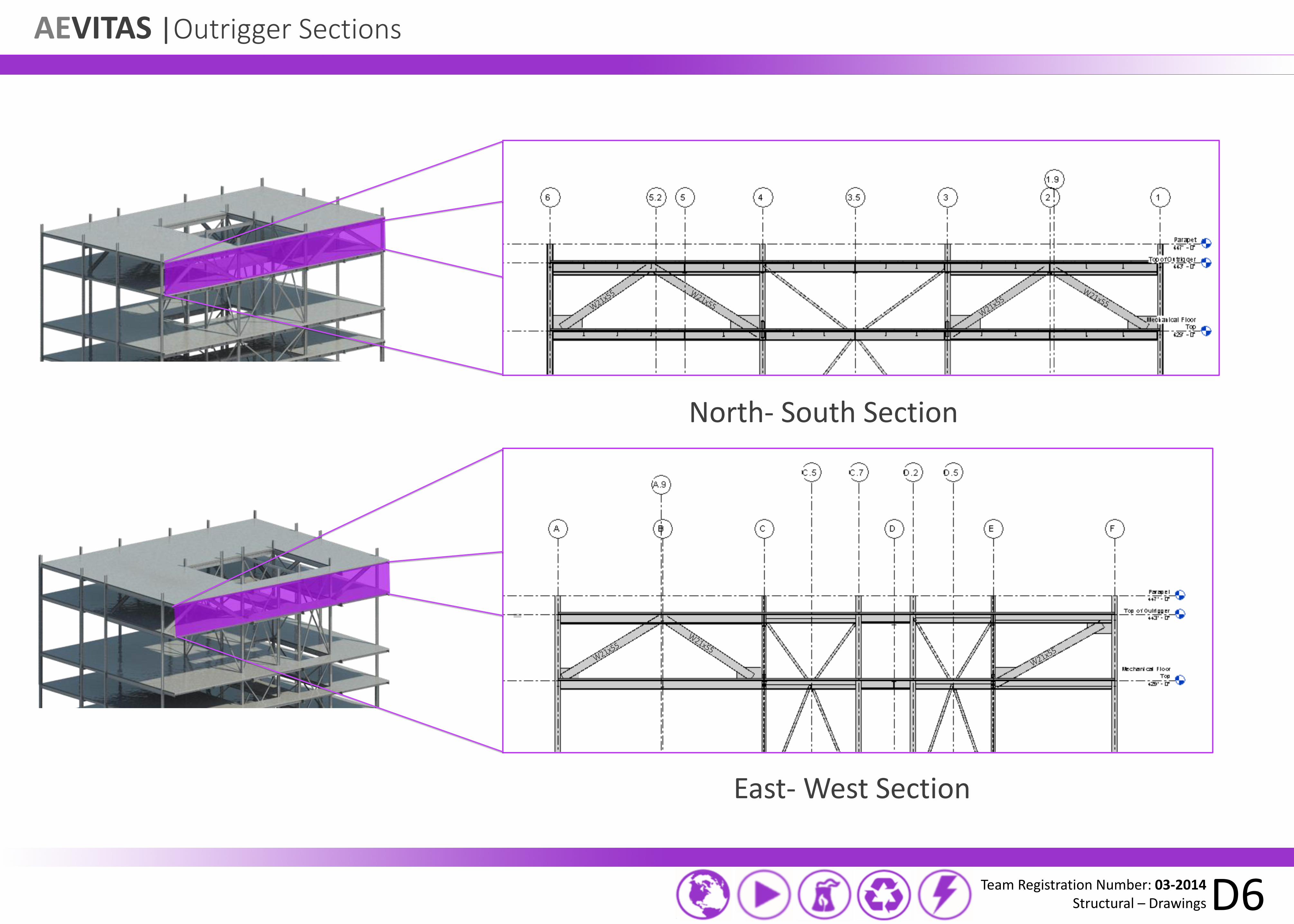
AEVITAS |Outrigger Sections
Team Registration Number: 03-2014 Structural – Drawings D6
North- South Section
East- West Section
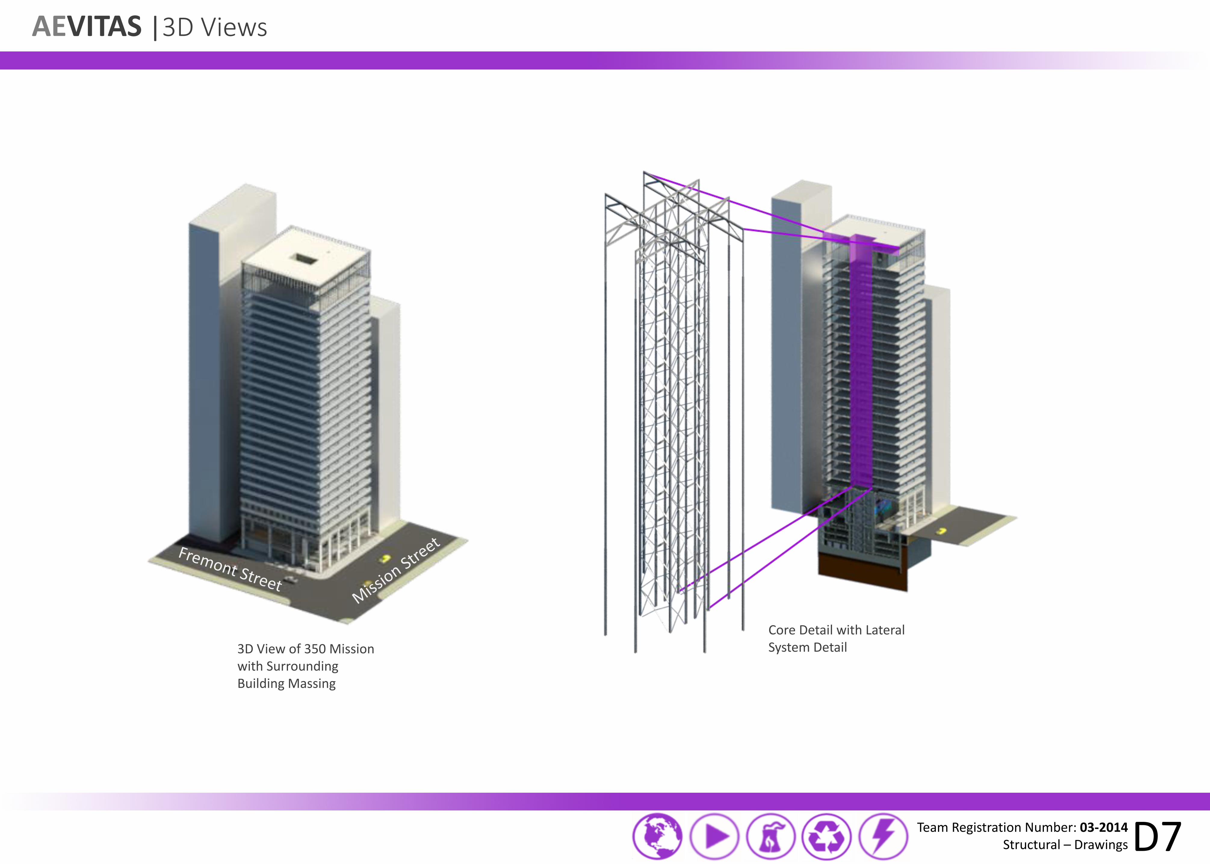
AEVITAS |3D Views
Team Registration Number: 03-2014 Structural – Drawings D7
3D View of 350 Mission with Surrounding Building Massing
Core Detail with Lateral System Detail

AEVITAS |Loading Diagrams
Team Registration Number: 03-2014 Structural – Drawings D8
80 psf Open Office 80 psf Closed Office 70 psf Mechanical 100 psf Stairs 50 psf Storage 100 psf Bathrooms Opening
40 psf Open Floor 23 kips Cooling Tower 22 kips Chillers 100 psf Stairs 35 psf Electrical Room 80 kips Potable Water 60 kips Fuel Cell .7 kips Boilers 50 psf Service Elevator Access Opening
Typical Office Loading Diagram Mechanical Penthouse Loading Diagram
The majority of the floor area is designed for 80 psf. This allows for flexibility to the space, while still maintaining a proper load requirement for any path of egress. These two areas are indicated in red and orange. The rest of the spaces are fixed in nature and are designed according to what code allows.
The open floor plan is designed to hold maintenance workers and light storage. The areas underneath the specific mechanical equipment is designed to hold the weight of the equipment during operation as well as the concrete pad with springs to dampen the vibrations from the equipment. The rest of the fixed spaces are designed to meet code requirements.

AEVITAS | Seismic Response
Team Registration Number: 03-2014 Structural – Drawings D9
Building Displacements for Design Earthquake
Modal Response of the Structure
30 inch displacement
Mode 1: 2.003 seconds Mode 2: 1.673 seconds Mode 3: 1.487 seconds

AEVITAS |Renderings
Team Registration Number: 03-2014 Structural – Drawings D10
3D Structure
Radiant Flooring Detail above Concrete Deck and Beams
Lobby View
Façade View


![Untitled-1 [] · 2020. 8. 22. · ORT Anthea Aromatics - Maharashtra The association with DRT Anthea involved their aroma chemical manufacturing plant. Aevitas has provided basic](https://static.fdocuments.net/doc/165x107/61197c8259fc2a585b0007af/untitled-1-2020-8-22-ort-anthea-aromatics-maharashtra-the-association.jpg)