Unit 3 Sensor & Actuator II
98
Sensors are the components of the system that provide the inputs that enable the computer ( ECM ) to carry out the operations that make the system function correctly . In the case of vehicle sensors , it is usually a voltage that is represented by a code at the computer’s processor . If this voltage is incorrect the processor will probably take it as invalid input and record a fault
description
power point for automotive engineering
Transcript of Unit 3 Sensor & Actuator II

Sensors are the components of the system that provide
the inputs that enable the computer ( ECM ) to carry out the operations that make the system function correctly . In the case of vehicle sensors , it is usually
a voltage that is represented by a code at the computer’s processor . If this voltage is incorrect the processor will probably take it as invalid input and record a fault

Actuator are the devices , such as fuel injector ,
ignition coils , ABS modulator and etc , which are
operated by outputs from ECM . This means that they
are normally electromechanical devices
Sensor & actuators play a critical role in determining
automotive control system performance .
Next picture shows block diagram of a typical electronic engine
control system . All critical engine control functions are based on
measurements made by various sensors connected to the engine .
Computations made within the engine controller based on the
inputs and outputs signals to actuators .

Typical electronic engine control system
Blue ~ actuator Red ~ sensor

Variables to be measured in engine control :- Mass Air Flow ( MAF ) rate Exhaust gas oxygen concentration (possibly
heated) Throttle plate angular position Crankshaft angular position / RPM Coolant Temperature Intake air temperature Manifold absolute pressure ( MAP ) Differential exhaust gas pressure Vehicle speed Transmission gear selector position

In additional to measurements of the above variables,
engine control is also monitored by switches below :-
Air conditioner clutch engaged Brake on / off Wide open throttle Closed throttle

An Engine requires the correct air-fuel ratio .
ECM needs a constant flow of information about the
amount of air flowing to the engine .
With this information , and data stored in its memory ,
the ECM can than send out a signal to the injectors , so
that they provide the correct amount of fuel .

So , a mass air flow sensor is used to determine the
mass of air entering an electronically fuel-injected
Engine .
Mass flow sensors are also used in industry to measure
many fluids and gases

Output voltage vs air flow
Typically the
conversation of
MAF to voltage
is slightly nonlinear
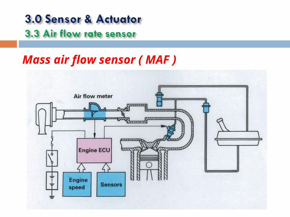
Mass air flow sensor ( MAF )

The amount of air flowing into the intake manifold must be accurately measured . The ECM must
have this information to calculate the amount of fuel to beinjected .
Air flow can be measured : - 1 ) Directly2 ) indirectly

Direct measurement 1 ) Vane
2 ) air-flow sensor plate
3 ) hot-wire induction
4 ) heated film
Indirect measurement 1 ) throttle position
2 ) engine speed
3 ) intake manifold vacuum or MAP

HOT WIRE TYPEA platinum wire is in the path of the incoming air through the air-
flow meter . The wire is kept hot by an electric current flowing
through it . However , the air flow cools the wire . The more air
that passes through the air-flow meter , the more heat that is lost
from the wire . The system keeps the wire at specific temperature
by adjusting current flow . If more air flows through and takes
more heat from the wire , the system send more current through .
This maintains the temperature . The amount of current required is
therefore a measure how air is flowing through . The ECM reads
this varying currents as air flow .

HOT WIRE TYPE
Hot Wire Thermister
Atmospheric Temp. Sensor

HOT WIRE TYPE

HOT WIRE TYPE

HOT WIRE TYPE

HOT WIRE TYPESome of the benefits of a hot-wire MAF compared to other
meter:-
1. Smaller overall package
2. Less expensive
3. Separate temperature and pressure sensors are not required ( to determine air mass )
There are some drawbacks :-
1. Dirt and oil can contaminate the hot-wire deteriorating its accuracy
2. Installation requires a laminar flow across the hot-wire

VANE TYPEThe vane type air flow meter used in some pulsed fuel injection
systems such as the Bosch L system . The spring-loaded vane is in
the air-intake passage of the air flow meter . Air flowing through
forces the vane to swing . The more air , the more the vane swing.
A vane position sensor works like the rotary throttle-position
sensor . Depending on its position , it sends varying voltage
signals to the ECM . This tells the ECM how much air is flowing
through . The ECM then adjusts fuel flow to match

VANE TYPEThe vane measures air volume , not mass , however by
measuring
the air temperature and pressure to determine air density , a true
mass airflow calculation can be achieved .
The vane meter approach has some drawbacks :-
1. Its moving electrical contact can wear
2. Finding a suitable mounting location within a confined engine compartment is problematic
3. The vane has to be oriented with respect to gravity .

VANE TYPE ~ OPERATION & FUNCTION

VANE TYPE

VANE TYPE

AIR FLOW SENSOR PLATEThe air-flow sensor plate is used in mechanical
continuous-
injection system . The plate is in the intake-air passage of the air-
flow meter . As air flow increases , the plate moves higher . This
lifts a control plunger in the fuel distributor to allow more fuel to
the injectors . The added fuel flow matches the additional air
flow

Karman vortex type

Karman vortex type ~ operation & function

Karman vortex type ~ electrical circuitry

Karman vortex type

HEATED FILM TYPEThe heated film consists of metal foil or nickel grid
coated with a
high-temperature material . Current flowing through the film heats
it . Air flowing past the cools it . Like the heated wire , the system
maintains the film at a specific temperature . The amount of
current required is a measure of air flow .

HEATED FILM TYPE

HEATED FILM TYPE

Hummer H2 Nissan Sentra 2000-2002 1.8L
Toyota Corolla 2001 Peugeot 205 1.6i
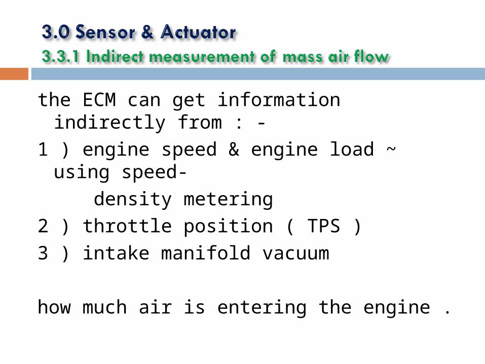
the ECM can get information indirectly from : -
1 ) engine speed & engine load ~ using speed-
density metering 2 ) throttle position ( TPS ) 3 ) intake manifold vacuum
how much air is entering the engine .

Throttle Position Sensor ( TPS )
A throttle position sensor is a sensor used to monitor the position
of the throttle in an internal combustion engine . The sensor is
usually located on the butterfly spindle so that it can directly
monitor the position of the butterfly throttle valve .
On some engines , when the throttle valve closes during
deceleration , the ECM shuts off fuel flow . This prevent an over-
rich mixture during deceleration

The ECM must always know the position of the throttle valve .
The ECM must match fuel flow with air flow to feed the engine the
proper air-fuel mixture
There are two types of throttle position sensor :-
1 ) rotary throttle position sensor
2 ) linear throttle position sensor

Refer to rotary throttle-position sensor , it has a coil of resistance
wire in the form of a half circle . One end connects to ground .
The other end connects to a 5-volt source from the ECM .As the
throttle-valve position changes , the viper blade moves along the
coil . When the throttle valve is closed , the blade is at the
grounded end of the coil . Only a small voltage signal is sent to
the ECM . As the throttle valves moves towards the open position ,
the viper blade swings towards the 5-volt end of the coil . This
sends an increasing voltage signal to the ECM . The voltage tells
the ECM the exact position of the throttle valve .

Rotary throttle position sensor
electrical schematic

Linear throttle position sensor
electrical schematic

Throttle Position Sensor ( TPS )
As the throttle position changes , the wiper blade moves which
changes the voltage signal to the ECM

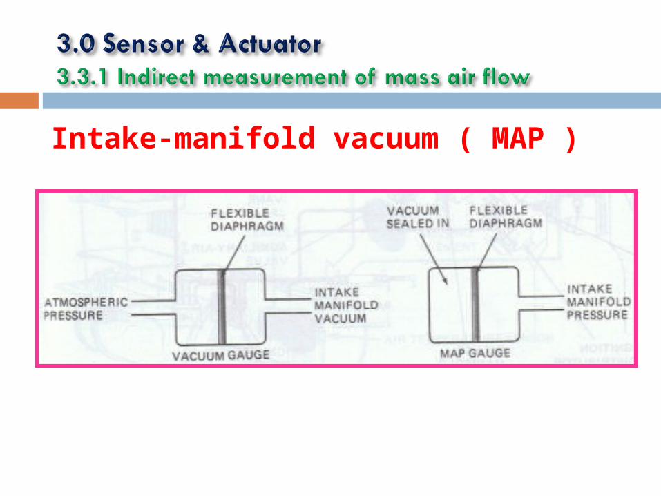
Intake-manifold vacuum ( MAP )
Intake manifold vacuum is measured in two ways :-
1 ) With a vacuum gauges
2 ) With a manifold absolute-pressure gauges ( MAP )
The vacuum gauge measures intake-manifold vacuum against
atmospheric pressure ( which varies ) . The MAP gauge measures
intake-manifold vacuum against a sealed-in vacuum (which does
not vary) . Therefore , the MAP gauge is more accurate .
Intake-manifold vacuum ( MAP )

The crankshaft-position sensor or simply crank sensor reports
1 ) crankshaft speed ( RPM )
2 ) piston position
to the ECM / ignition module .
The ECM uses this data to control fuel metering , ignition spark
advance and the shifting of electronic automatic transmission and
transaxles .

Angular position can be sensed on the : -
1 ) crankshaft
2 ) camshaft .
The camshaft is driven from the crankshaft through a 1: 2 reduction
drive train which can be gears , belt , or chain . Therefore , the
camshaft rotational speed is one-half that of the crankshaft , so the
camshaft angular position goes from 0 to 360 for one complete
engine cycle . Crankshaft is potentially better for the accuracy compare to camshaft .

Position of Camshaft & crankshaft

The principles in measuring rotating shafts can be illustrated as on
next page .
The engine is viewed from the rear side . The crankshaft angular
position is the angle between the reference line and the mark on
the flywheel .
If the mark is directly on the zero line , this is an angular position
of zero degrees .
If the crankshaft rotates and the angle increases from zero to 90
degrees , it called position of 90 degrees .
This information is used by the electronic controller your system .
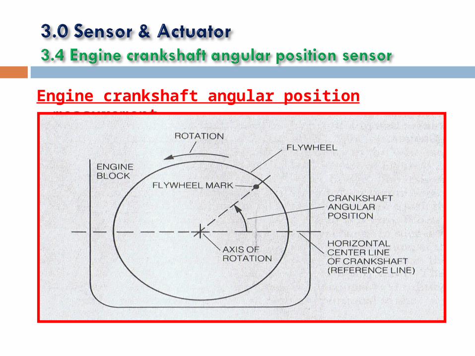
Engine crankshaft angular position measurement

It is desirable to measure engine angular position with a
noncontacting sensor to avoid mechanical wear and changes in
accuracy of the measurement .
Two most common method for noncontact sensor as a physical
basis :-
1 ) magnetic field
2 ) optic

crankshaft-position sensor

This sensor consists of a permanent magnet with a coil of wire
wound around it . A steel disk that is mounted on the crankshaft
( usually in front of the engine ) has tabs that pass between the
pole pieces of the magnet . Picture shows that the steel disk has
four tabs which is appropriate for an 8-cylinder engine .
This sensor is based on the concept of a magnetic circuit .

Magnetic reluctance crankshaft position sensor

The response of the magnetic circuit to the magnetic field is
called magnetic flux .
The magnetic flux is similar to the current that flows when a
resistor is connected across a battery to form a closed electrical
circuit .
The magnitude of the magnetic flux that flow through the
magnetic circuit depends on the position of the tab , which in turn,
depends on the crankshaft angular position .
The rate of change of the magnetic flux is proportional to the
voltage , Vo .

Magnetic circuit of the reluctance sensor

Output voltage waveform from the reluctance crankshaft position sensor coil
The coil voltage Vo begins to increase from zero as a tab begins
to pass between the pole piece , reaches a maximum , then falls
to zero when the tab is exactly between the pole piece .
Although the value of magnetic flux is maximum at this point , the
rate of change of magnetic flux is zero ; therefore , the induced
voltage in the sensing coil is zero .

Output voltage waveform from the reluctance crankshaft position sensor coil

Disadvantage
Since the magnetic flux must be changing to induce a voltage , in
the sensing coil , its output voltage is zero whenever the engine is
not running , regardless of the position of the crankshaft . This is a
disadvantage for this type of sensor because the engine timing
cannot be set statically .

The hall element is a small , thin , flat slab of semiconductor
material . When a current , I , is passed through this slab , a
voltage is developed across the stab perpendicular to the
direction of current flow and direction of magnetic flux .
This voltage is proportional to both the current and magnetic flux
density that flows through the slab .
This effect , the generation of a voltage that is dependent on the
magnetic field , is called the hall effect .


Hall-effect position sensor

In the optical crankshaft position sensor , a disk coupled to the
crankshaft has holes to pass light between the LED and the
phototransistor .
The hole in the disk allows transmission of light through the light
pipes from the light-emitting diode ( LED ) source to the
phototransistor used as a light sensor .
The pulse of light is detected by the phototransistor and coupled
to an amplifier to obtain a satisfactory signal level .

One of the problem with optical sensors ~ they must be protected
from dirt and oil , otherwise they will not work properly .
Advantage ~ Sensor can sense position without the engine
running and that the pulse amplitude is constant with variation of
speed .

Optical position sensor

Most throttle angle sensors are essentially potentiometers . A
potentiometer consists of a resistor with a movable contact , as
illustrated below .
The only disadvantage of the potentiometer for automotive
applications is its analog output . For digital engine control , the
voltage v ( a ) must be converted to digital format using an
analog-to-digital converter .

Throttle angle sensor : A potentiometer

Temperature is an important parameter throughout the automotive system . In operation of an electronic fuel control system it is vital to know the temperature of the coolant , the temperature of the inlet air and
the temperature of the exhaust gas oxygen sensor . We can understand basic operation of most of the temperature sensors with the explanation of a typical coolant sensor

A typical coolant sensor consists of a thermistor
mounted in a housing that is designed to be inserted
in the coolant stream . This housing is typically
threaded with pipe threads that seal the assembly
against coolant leakage

The sensor is typically connected in an electrical circuit as shown
on picture which Rt is sensor resistant and Vt is output voltage .
The sensor output voltage varies with temperature ; that is , the
output voltage decreases as the temperature increases

Electric engine-cooling fan
Coolant temperature sensor

Typical coolant temperature sensor circuit
Vt decreases as temperatureSensed by Rt increases

The sensors that we have discussed before are part
of open-loop ( feedback ) control .
The next sensors are for closed-loop control .

Introduction
An oxygen sensor, or lambda sensor, is an electronic
device that measures the proportion of oxygen (O2) in
the gas or liquid being analyzed. It was developed by Robert Bosch GmbH during the late 1960s
under supervision by Dr. Günter Bauman.

Lambda Sensor
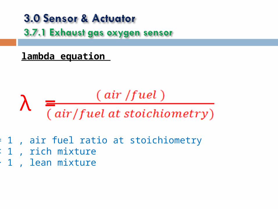
lambda equation
λ =
λ = 1 , air fuel ratio at stoichiometryλ < 1 , rich mixture λ > 1 , lean mixture

The EGO has normally two type of materials :-
1 ) Zirconium dioxide ( ZrO2 )
2 ) Titanium dioxide ( TiO2 )
As per shown on next picture , the voltage , Vo is generated
across the ZrO2 material and this voltage depends on the
exhaust gas oxygen concentration , which in turn depends on the
engine air/fuel ratio .

EGO Mounting & Structure

A simplified explanation of EGO sensor operation is based on the distribution
of oxygen ions . An ion is an electrically charged atom. Oxygen ions have two
excess electrons and each electron has a negative charge ; thus , oxygen ions
are negatively charged .
The ZrO2 has the tendency to attract the oxygen ions , which accumulate on
the ZrO2 surface just inside the platinum electrode .
The platinum plate on the air reference side of the ZrO2 is exposed to the
much higher concentration of oxygen ions than exhaust gas inside .
The air reference side becomes electrically more negative than the exhaust
gas side , therefore , an electrical fields exist across the ZrO2 an voltage , Vo ,
results .

EGO mounting & structure

Characteristic of oxygen sensor

Electrical circuitry

For a rich mixture there is a relatively low oxygen concentration
in the exhaust and a higher EGO sensor output .
For a lean mixture the exhaust gas oxygen concentration is
relatively high ( meaning that the difference between exhaust
gas and atmospheric oxygen concentration is lower ) , resulting in
a relatively low EGO sensor output voltage .
For a fully warmed EGO sensor the output voltage is about 1 volt
for rich mixture and about 0.1 volt for a lean mixture

Typical EGO sensor characteristics
The sensor output doesn’t change at exactly at the same point for increasing /
decreasing air/fuel ratio . This phenomenon is called hysteresis

Typical influence of mixture and temperature on voltage on EGO output voltage

Typical voltage switching characteristics of EGO sensor
Temperature affects switching times and output voltage . The time
per division is twice as much for the display at 350 degree as at
800 degree . This means that the switching times are roughly 0.1
second at 350 , whereas at 800 they are about 0.05 second .
This is a 2:1 change in switching times due to changing
temperature .

Typical voltage switching characteristics of EGO sensor

During combustion , sometimes occurs undesirable knock , most
commonly with high manifold pressure and excessive spark
advance . It is important to detect knock and avoid excessive knock
; otherwise there may be damage to the engine .
Inside the knock sensor is a piezoelectric element . Piezoelectric
elements generate a voltage when pressure or a vibration is
applied to them .
The way of controlling knocking is to sense when knocking begins
and then retard the ignition until the knocking stops .

Knock sensor

In additional to the set of sensors , electronic engine is critically
dependent on a set of actuators to control air/fuel ratio , ignition
and EGR .
In general , an actuator is device that receives an electrical input
and produces a mechanical or thermal output .
Example of actuators include various types of electric motors ,
solenoids and piezoelectric force generators .
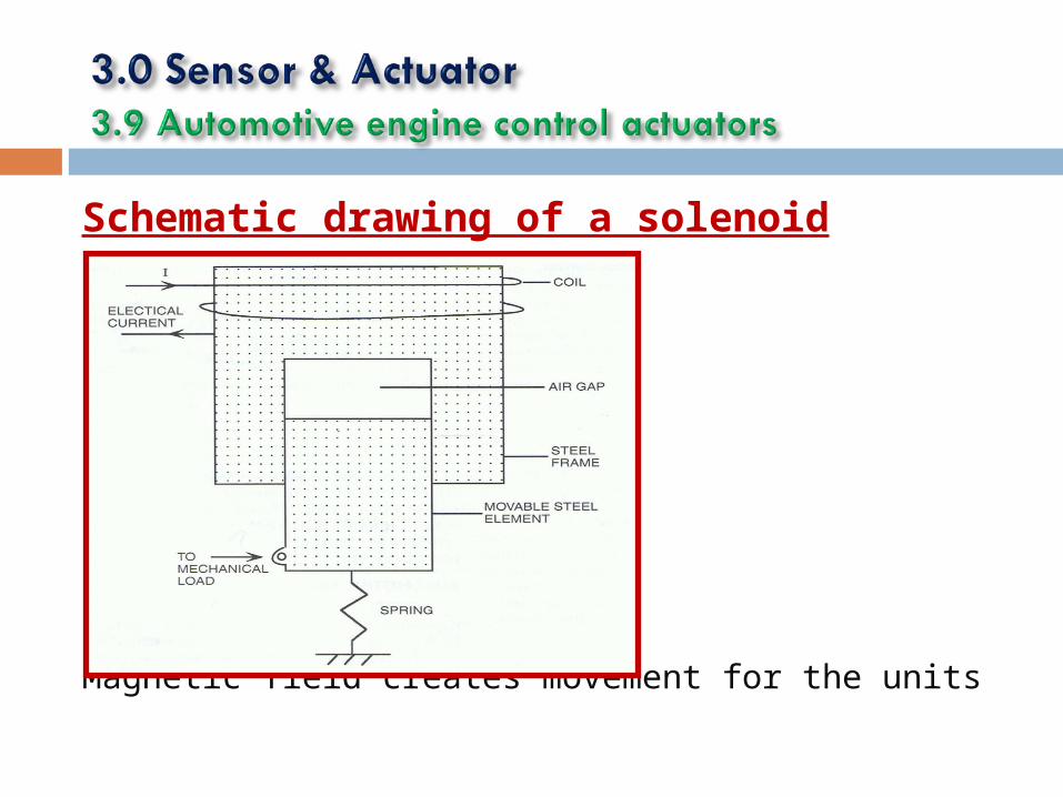
Schematic drawing of a solenoid
Magnetic field creates movement for the units

A fuel injector is a solenoid-operated valve . The valve opens and
closes to permit or block fuel flow to the engine . The valve is
attached to the movable element of the solenoid and is switched
by the solenoid activation .
The injector is open when the applied voltage is on and closed
when the applied voltage is off .

Schematic drawing of fuel injector

Please refer next picture :- The ratio of on time t to the period of the pulse T is called duty
cycle .
The fuel injector is energized for time t to allow fuel spray from
the nozzle into the air stream going to the intake manifold . The
injector is deenergized for the reminder of the period .
Therefore :-
1 ) a low duty cycle is used for a high air/fuel ratio ( lean mixture )
2 ) a high duty cycle is used for a low air/fuel ratio ( rich mix )
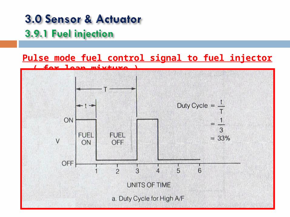
Pulse mode fuel control signal to fuel injector ( for lean mixture )

Pulse mode fuel control signal to fuel injector ( for rich mixture )

EGR is utilized to reduce NOx emission . When the correct amount of EGR has been determined by the controller based on
measurements from the various engine control sensors , the
controller sends an electrical signal to the EGR actuator .There are many EGR configurations .One on
them is shown on the next picture .

This actuator is a vacuum-operated diaphragm with a spring that
holds the valve closed if no vacuum is applied .
The vacuum is applied by the intake manifold and controlled by
solenoid valve .
Whenever the solenoid is energized , the EGR valve is opened by
the applied vacuum .
The amount of valve opening is determined by the average
pressure on the vacuum side of the diaphragm . When the EGR
valve is open , exhaust gas flows into the intake manifold .

EGR Actuator Control

The equivalent of an actuator for the ignition system on the
engine is the combination of
1 ) the spark plug
2 ) the ignition coil
3 ) driver electronic circuits
This is the subsystem that receives the electrical signal from the
engine controller and delivers as its output the spark that ignites
the mixture during the end of the compression stroke .

A relative huge current flow through the primary coil , P . At
appropriate time for ignition , the controller switches off the base
current , causing the transistor to be non conducting . At this time ,
the primary current drop to zero very quickly , causing the
magnetic strength to drop rapidly .
It generates a very high voltage ( 30,000 to 50,000 volts ) ,
which , in turn , creates the spark across the spark plug electrode.

Electronic
ignition
subsystem