Unit-3 RADAR SERVICES AND FIS 1401
85
1 1 Unit-3 RADAR SERVICES AND FIS 1401 co-ordination between radar / non radar control – emergencies FLIGHT INFORMATION ALERTING SERVICES, COORDINATION, EMERGENCY PROCEDURES AND RULES OF THE AIR
-
Upload
melvina-hartnett -
Category
Documents
-
view
45 -
download
2
description
Unit-3 RADAR SERVICES AND FIS 1401. co-ordination between radar / non radar control – emergencies FLIGHT INFORMATION ALERTING SERVICES, COORDINATION, EMERGENCY PROCEDURES AND RULES OF THE AIR. 1. Syllabus. - PowerPoint PPT Presentation
Transcript of Unit-3 RADAR SERVICES AND FIS 1401
11
Unit-3RADAR SERVICES AND FIS1401
Unit-3RADAR SERVICES AND FIS1401
co-ordination between radar / non radar control – emergencies FLIGHT INFORMATION ALERTING SERVICES, COORDINATION, EMERGENCY PROCEDURES AND RULES OF THE AIR
22
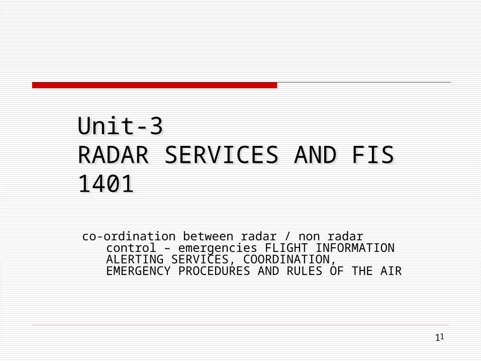
Syllabus1. Radar service, Basic radar terminology – Identification
procedures using primary / secondary radar performance checks – use of radar in area and approach control services – assurance control and co-ordination between radar / non radar control – emergencies
2. Flight information and advisory service – Alerting service – Co-ordination and emergency procedures – Rules of the air.
3
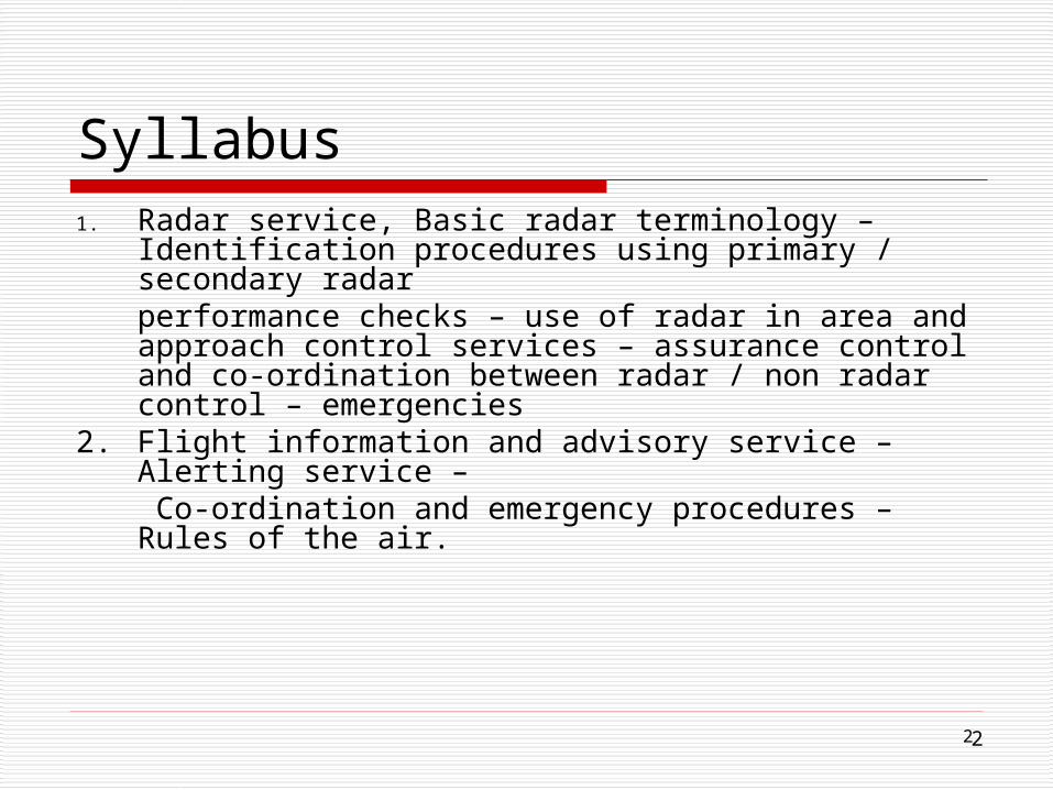
Key Topics Covered
1. Radar Control & Non Radar Control2. Methods of Improving an existing
Airport to a New Airport3. Air Transportation in India4. Flight Information5. Difference between ICAO system and
Calvert System

4
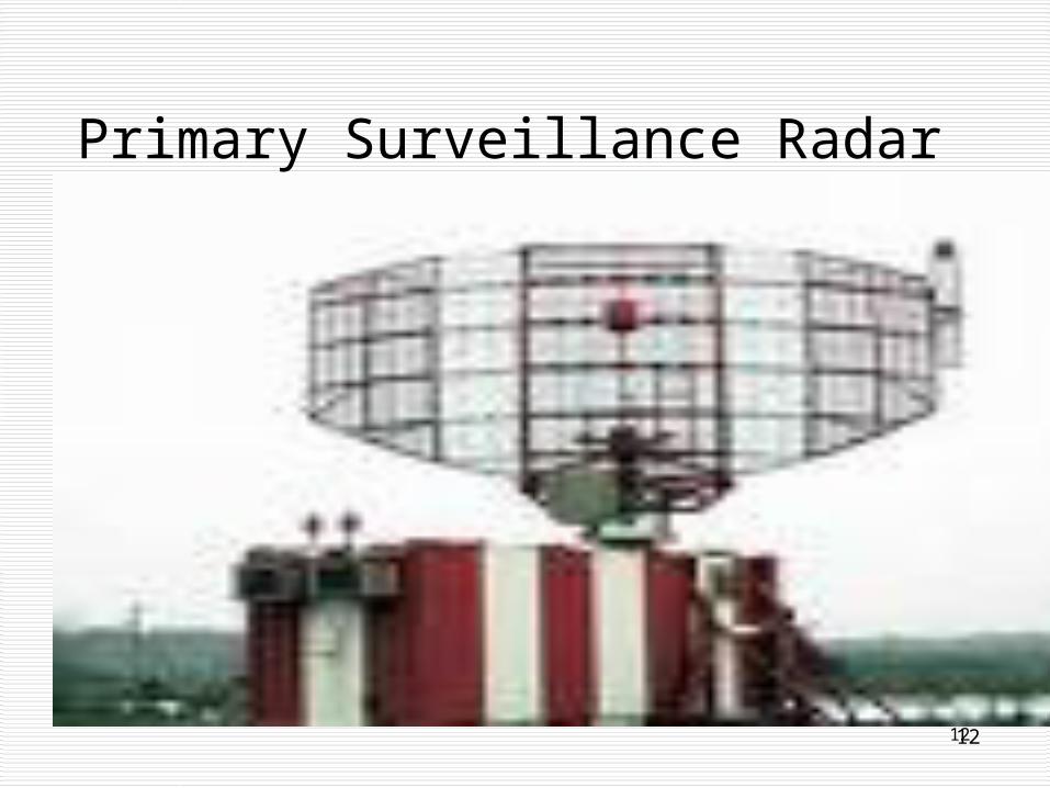
Primary Surveillance Radar (PSR)

5
Secondary Surveillance Radar (SSR)
6
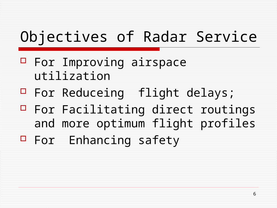
Objectives of Radar Service
For Improving airspace utilization For Reduceing flight delays; For Facilitating direct routings and
more optimum flight profiles For Enhancing safety
7
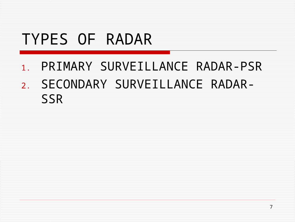
TYPES OF RADAR
1. PRIMARY SURVEILLANCE RADAR-PSR2. SECONDARY SURVEILLANCE RADAR-
SSR
88
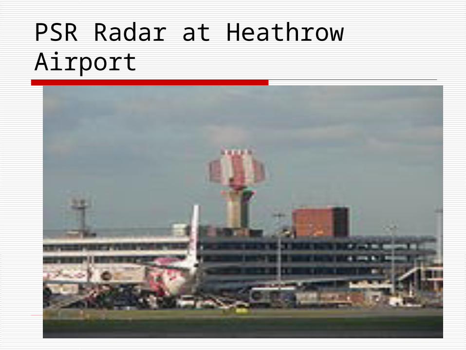
PSR Radar at Heathrow Airport

9
ATC RADAR
SSRPSR
By reflection of an EchoPulse from a Site on a Monitor
For Airport Enroute Surveillance
Thru a TransponderAt the Aircraft
A Passive Radar An Active Radar

1010
ATC RADAR
ATC RADAR = PSR + SSR Airport Surveillance radar Air Route Surveillance Radar
11
PSR
Principle, Advantages and Disadvantages
1212
Primary Surveillance Radar

13
PSR
1. Transmits radar energy detected by the aircraft by reflected radar energy
2. Aircraft return is displayed on the ATC console at a range and bearing with aircraft position
3. Coverage limited between 80NM to 200NM for en-route control purpose
4. Used as a Backup to SSR

14
Features of PSR
Monitor all the aircraft in the airspace-upto a distance of 65 NM at S band (2.7 to 2.9 GHz) @ 25 KW peak -Av 2 KW @ 15 rpm.
Operating totally independently of the aircraft target.
Weather conditions detected in six levels of rain intensity
Provide range & direction information from the reflected signal from the aircraft.
Passive Radar-no action from the aircraft required to provide to ATC
Primary Radar

15
Advantages of PSR
Operates independently irrespective of target
No Action Reqd from the Aircraft
16
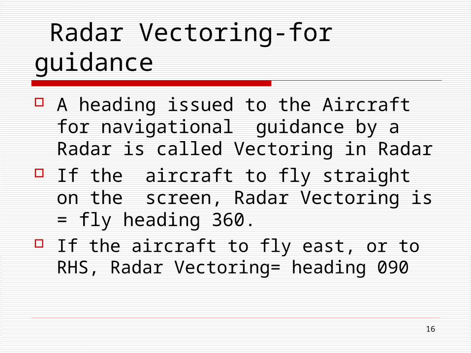
Radar Vectoring-for guidance
A heading issued to the Aircraft for navigational guidance by a Radar is called Vectoring in Radar
If the aircraft to fly straight on the screen, Radar Vectoring is = fly heading 360.
If the aircraft to fly east, or to RHS, Radar Vectoring= heading 090

17
SSR (Special service Codes) Code
two groups; discrete and non-discrete A non discrete ends in 00(7600 'Radio
Failure‘) and any code not ending 00 is discrete code

18
Disadvantages
TX signal limited by ‘line of sight’ interrupted by buildings, hills & mountains.
More power be radiated for getting returns from the target & little power is recd.
Hence displayed target will be fading (not clear).

19
SSR
Principle, Advantages and Disadvantages

2020
Secondary Surveillance Radar

2121
SSR-Secondary Surveillance Radar
Provide
1. Range, 2. Bearing, 3. Altitude and 4. Identity (call sign) of an
aircraft.

2222
SSR-Beacon

23
Characteristics of Secondary Surveillance Radar (SSR)
An Active Surveillance Radar for accurate information working at 1030 MHz with Mode S interrogation
Size Smaller than r than PSR, be mounted either single or Combined with PSR (ARS11)
Aaircraft detected thru 'transponder‘ fitted at the aircrafat.
Transponder - radio TX & RX receiving on one frequency (1030 MHz) and transmitting on another (1090 MHz).
SSR detects 1. identification of the aircraft, 2. the height of aircraft, 3. speed and 4.direction of flight.

2424
Radar Beacon At Schipol Airport

25
Schematic of SSR & PSR
26
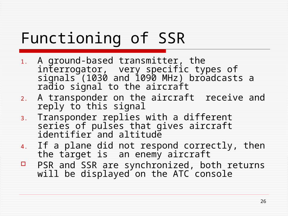
Functioning of SSR1. A ground-based transmitter, the
interrogator, very specific types of signals (1030 and 1090 MHz) broadcasts a radio signal to the aircraft
2. A transponder on the aircraft receive and reply to this signal
3. Transponder replies with a different series of pulses that gives aircraft identifier and altitude
4. If a plane did not respond correctly, then the target is an enemy aircraft
PSR and SSR are synchronized, both returns will be displayed on the ATC console

27
Airborne Architecture at Aircraft
28
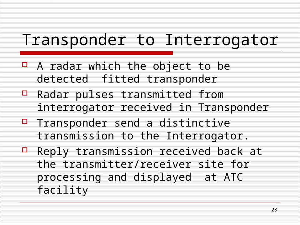
Transponder to Interrogator A radar which the object to be detected
fitted transponder Radar pulses transmitted from interrogator
received in Transponder Transponder send a distinctive transmission
to the Interrogator. Reply transmission received back at the
transmitter/receiver site for processing and displayed at ATC facility
29
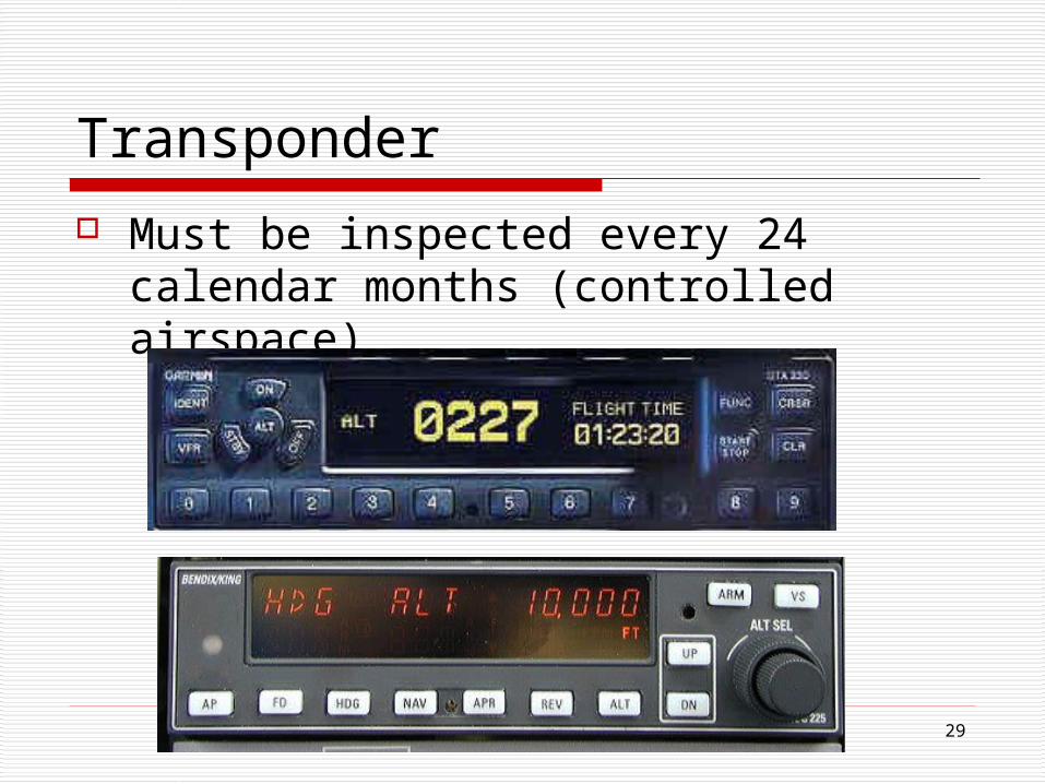
Transponder
Must be inspected every 24 calendar months (controlled airspace)

3030
SSR Identification Procedure
1. SSR transponder selected on Mode 3/A (4096 codes) and Mode C simultaneously
2. Pilots will maintain the same setting in the Transponder
3. ATC instruct the dep. Flight to operate the transponder
31
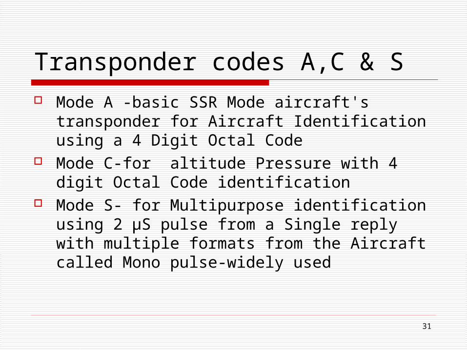
Transponder codes A,C & S Mode A -basic SSR Mode aircraft's
transponder for Aircraft Identification using a 4 Digit Octal Code
Mode C-for altitude Pressure with 4 digit Octal Code identification
Mode S- for Multipurpose identification using 2 µS pulse from a Single reply with multiple formats from the Aircraft called Mono pulse-widely used
32
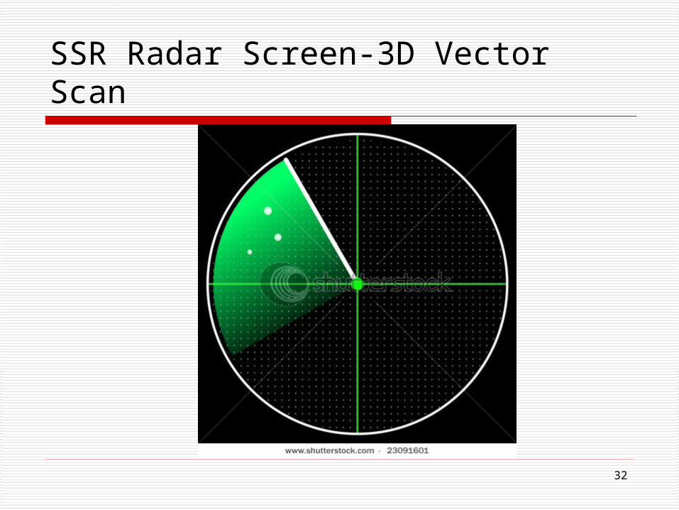
SSR Radar Screen-3D Vector Scan

33
Advantages of Secondary Surveillance Radar SSR
Higher Range Low power required to radiate the signals,
thus reduce the cost. Providing more information: aircraft’s
identity, altitude & speed. Giving a clearer display Easier to identify aircraft on SSR
(interrogation)
34
Comparison between PSR & SSR

35
PSR vs. SSR1 Give Direction, height
and distance Give additional info of signal identification and altitude
2 Works on Passive Echo Works on Active Echo (Thru Transponder)
3 No reflected signal processing
Reflected signal processing
4 No interrogation Interrogation
5 Back up to SSR By itself
36
RADAR SERVCE AREAS
Types and Purpose

3737
Radar Service Areas
1. AERODROME CONTROL SERVICE AREA-for apron management at the aerodrome
2. AREA CONTROL SERVICE AREA- for enroute air traffic
3. APPROACH CONTROL SERVICE AREA for arriving and departing air traffic
38
Aerodrome Control Service ADCS Service given to the aircraft from the
control tower (–> TWR) with its extended field of vision, to start engines for take off or to land
ADCS directs taxiing aircraft and manages airborne traffic in the immediate vicinity of the airport.
39
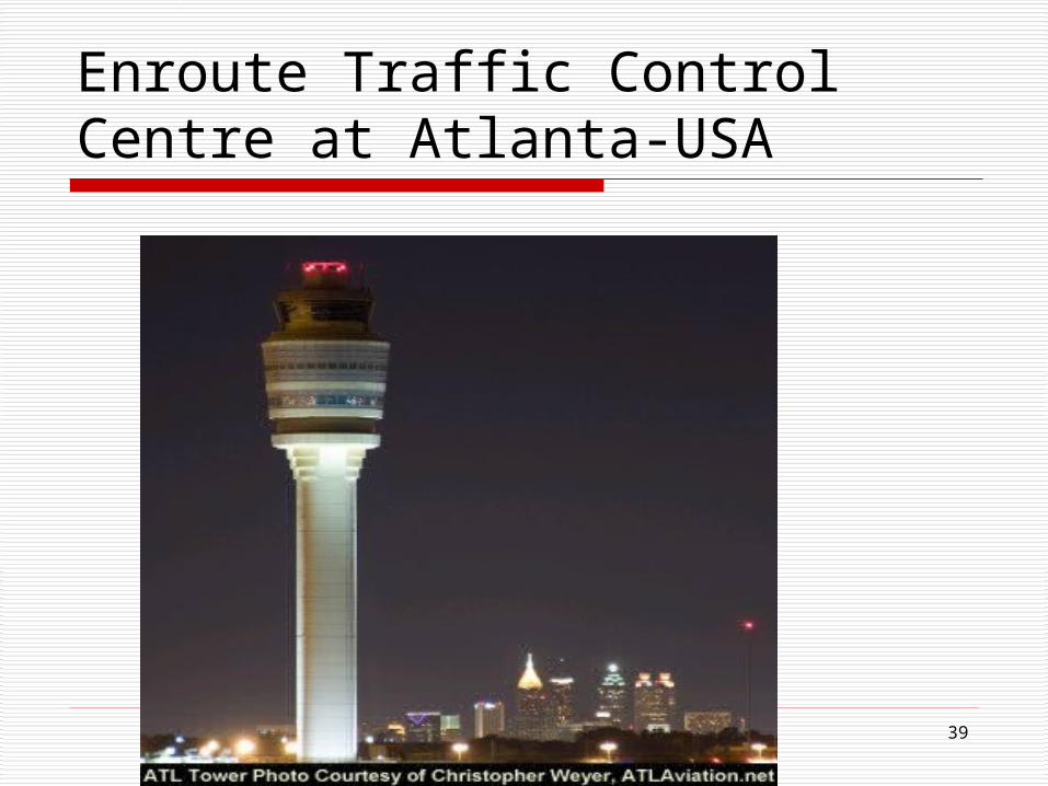
Enroute Traffic Control Centre at Atlanta-USA

40
Area Control Service
ACS for the safe flow of traffic along airways (–> En-route) and in certain portions of terminal control areas (–> APP).
ACS cover for various altitudes and geographic sectors
41
Minimum Safe Altitude-MSA
An Altitude-Allowing adequate vertical clearance from terrain and manmade obstacles, and allowing proper navigational functions.
Depending on VFR & IFR For VFR flights 1000’ in non
mountainous area and 2000’ in mountanous area

42
Minimum Safe Altitude

43
Minimum Enroute Altitude-MEA Lowest published altitude of an aircraft
flying on IFR legally on a given route MEA listed as a Number-6500-the lowest
minimum altitude ensuring signal coverage from navigational aids
Minimum Enroute Altitude-determined by the local terrain and navigation equipment –
At night aircraft not allowed to descend a min enroute altitude

44
MEA-6500

45
FIS on Screen

46
Air space Traffic In Miami

4747
ARTCC-Air Route Traffic Control Centre-Enroute Air Route Surveillance Centre=Air
Route Traffic Control Centre. Objective: For providing air traffic
control service on IFR flight plan in controlled airspace & on Enrouote
For assistance service to VFR Flight

48
Approach Control Service
Approach control service for flights arriving and departing from an airport in a specific control zone (–> CTR) and in terminal control area (usually within a 50 km radius of the airport)

49
Non Radar Control & Radar Control
Definition, Techniques in each, Radar Separation Control

50
Non Radar Control
1. a method of providing Air Traffic Control service without the use of radar, used in Sparingly populated Areas
2. Used in Low Traffic Airports

51
Radar Control Services
1. Services for D & E Airspace2. Radar Advisory Service to F
Airspace3. Radar Flight Information
Service to G airspace

52
( Horizontal )Radar Separation Minimum 5 NM horizontal radar separation up to 60
NM from radar head except 6 NM horizontal radar separation to aircraft in the approach and departure phases of flight shall be applied
the LIGHT an aircraft operating directly behind the HEAVY aircraft at the same altitude or less than 1000 ft below

53
Techniques of Non Radar Control
1. By Horizontal separation between Aircrafts, based upon time, or routes, or aircraft position based on ground-based navigation aids
2. By Altitude grouping -the easiest and most common method for cruising altitude as in trans-oceanic sectors.
3. By route intersection points (fix posting area) easiest Non Radar control

54
Types of Non Radar Separation
1. Vertical separation –2. Longitudinal separation – 3. Lateral separation – 4. Geographical separation – 5. Omni Track Separation –6. Visual separation

55
When light aircraft operating directly behind a Heavy aircraft

56
When light aircraft crossing behind a Heavy Aircraft

57
Co-ordination between radar / non radar control
1. Adequate separation between aircraft maintained between the radar-controlled and non radar control.
2. Radar separation based on the use of RPS shall be applied
3. Under no circumstances the edges of the radar position should touch or overlap
4. Radar separation be maintained between the radar-controlled flights and any other observed radar position

58
Approach Radar Procedure
Sequence of arriving aircraft informed by the approach radar controller to Aerodrome controller
pilot is advised the type of approach as well as the runway to be used

59
co-ordination between radar / non radar control
Radar Separation minimum & coordination

60
Radar Identification and Coordination
Performance checks – use of radar in area and approach control services – assurance control and co-ordination between radar / non radar control – emergencies

61
PERFORMANCE CHECKS
1. Adjusting the radar display2. Carrying out checks on the accuracy of
the display as per ATC manual3. Functional capabilities of the radar system
is satisfied by the controller4. If there is any difficulty in the peformance,
it is reported

62
RADAR IDENTIFICATION
PSR Identification Procedures SSR Identification Procedures

63
PSR Identification
I. By Departing Aircraft MethodII. By position report method-
positionIII. By Turn Method

64
PSR Identification 1. Departing Aircraft Method: By correlating an observed
radar position indication with an just departed aircraft (within 1 NM of runway)
2. By position report method-position indication with an aircraft reporting its position
3. By Turn Method: An aircraft identified by ascertaining the aircraft heading

65
SSR Identification
1. Through a Call Sign or Code2. By Direct recognition3. By transferring Radar Identification
to the pilot4. By observation to a set of Codes

66
SSR Identification
1. Aircraft identification by a SSR Label thru a code/call sign
2. By Direct recognition of the aircraft identification of a Mode S-equipped aircraft in a radar label;
3. By transfer of radar identification4. By observation of compliance with an
instruction to set a specific code;

67
Emergencies In the event of an emergency, every
assistance shall be provided by the radar controller, and
The procedures as per the situation Progress of an aircraft in emergency shall
be monitored and plotted on the radar display until the aircraft passes out of radar coverage,

68
COORDINATION AND RULES OF THE AIR
Co-ordination and emergency procedures

69
Services of the Air
1. Area Control Service-for Enroute2. Approach Control Service-50Km
radius3. Aerodrome Control Service-thru’ the
Control tower for starting the engine, take off and landing

70
Stages in Co-ordination between ATC Units
A. Announcing the flight and conditions for transfer of control
B. Coordination of transfer and agreement on the control conditions
C. Transferring of control to the accepting ATC unit or control sector.

71
Important Coordination Zones
1. Between ATC Centres 2. Between Area Control Service and
Approach Control Service3. Between Approach Control Service and
Aerodrome control Service4. Between ATC and Military service5. Between Met and ATC

72
Coordination between Area Control Service & approach control Service
A unit providing approach control service will issue clearances to any aircraft released to it by an ACC without reference to the ACC.
Take-off and Clearance ExpiryTimes –coordinate the departure with unit providing approach control service;
provide en-route separation for departing aircraft

73
Rules of the Air
1. Protect person and property2. Minimum Safe Altitude3. Cruising Levels4. Dropping or Spraying5. No towing by another aircraft6. No acrobatic flight7. No flying in Restricted Areas8. Right of way for heading and speed

74
Flight information and advisory service – Alerting service
Sigmet,FIS Scope,Air reporting on designated route,Air data transmission, Alerting service

75
SIGMET-Significant Meteorological Information
An advisory service providing meteorological information for the safety of all aircrafts
two types of SIGMET-s, convective and non-convective
Non connective Sigmet for severe turbulence or icing or sandstorm
Connective sigmet for thunderstorm

76
Vaisala (UK) Sigmet

77
Scope of Flight Information service1. SIGMET2. information regarding volcanic activity, volcanic
eruptions and volcanic ash clouds;3. Info concerning the release into the atmosphere of
radioactive materials or toxic chemicals;4. Information on changes in the serviceability of
navigation aids5. Information on changes in condition of aerodromes
and associated facilities,6. including information on the state of the

78
Air Reports on Designated Air Route
1. Moderate to severe Turbulence2. Severe Icing3. Hail4. cumulonimbus Cloud (type of cloud tall,
dense, and involved in thunderstorms)5. Any met condition in the opinion of the
pilot to affect aircraft operation

79
Cumulonimbus Cloud

80
Methods of Transmission of Air Data
A. By method of directed transmission on the initiative of the appropriate ATS unit to an aircraft
B. By an acknowledged transmission to all aircraft concerned
C. By a BroadcastD. By a data link

81
Air Traffic Advisory Service objective of the air traffic advisory service
is to make information on collision hazards more effective than it would be in the mere provision of FIS
It may be provided to aircraft in IFR flights in advisory airspace or on advisory routes (Class F airspace)

82
An air traffic services unit providingair traffic advisory service-Shall
Advise the aircraft to depart at the time specified and to cruise at the levels indicated in the flight plan
Suggest a course of action to avoid any hazard
Passing the traffic information to the aircraft as given by area control service

83
Alerting Service Phases
A. Uncertainty in phase-no communication from aircraft in less than 30’
B. Alerting phase no news of aircraft following A
C. Distressing Phase following A,B -with widespread enquiries

84
Alerting Service
To provide service when no communication from the aircraft in less than 30’
Alert in phase when communication with the aircraft fail
Provided to all aircraft as Traffic
control service

85
Flight Information Service-Chennai
1. Lateral and Vertical Airspace2. Unit providing Service-ACC Chennai3. Call Sign-Chennai Radar- RSR4. Frequency-118.9 MHz,125.7 MHz5. Airspace under ATS=F6. Airspace outside ATS=G