UNDERWATER NONDESTRUCTIVE TESTING OF SHIP HULL WELDS
32
SSC-293 UNDERWATER NONDESTRUCTIVE TESTING OF SHIP HULL WELDS JAN W 80 u1 -10 042 SHIP STRUCTURE......... ... .. u..w J
Transcript of UNDERWATER NONDESTRUCTIVE TESTING OF SHIP HULL WELDS
SSC-293
UNDERWATERNONDESTRUCTIVETESTING OF SHIP
HULL WELDS
JAN W
80 u1 -10 042SHIP STRUCTURE......... ... ..u..w J

o ITWCTgM• COMMIRTg
MeU 50? 8Ut2UVZM DMMGTm is eostituted to preseence a rsesarh
ptqram to Improve the hull structures of ships and other marine structures"by am eixzte6s of knowaedge pertainiing to dsip, materials and methods ofcomtrectum.
Odsf, Offtde of MAbr =t anlmf Assistat Adwiniotrator for"8s vb Coez'aW ieveDtaiw crnt
U. 5. cowt * "n'd Mar(itini A~niamiitrati~on
W.. P. N. UZD, Wr. P., a. XWLRADxr~etor Chiorf Brwmoh of M2rine 011Butt iht~itwgL Dip"Jon and Gas Operaiot~sNaval Sea *stems Cewnd U. S. Gdologioa Survey
Mf.&~ . EWNAN Mr. C. J. &WZ2STdVE
Am~ m~ B1wva of Abipping Ni ztary Seazift Como~d
LCDR 7. P*. RM0S U.S. Coast Guarad (Secretary)
SHIP STRUCTURE SUICBOIgTTEE
he SillP STRUCTURE SUCOMITTEE acts for the Ship StrvctureCAittee on technical matters by providing technical coordination for thedsterutnation of goals and objectives of the program, and by evaluatingand interpreting the results in term of structural design, construction and
operation.
U.S. COAST GUAUD WEITAJY SEALIFT cWoMS b
CAPT ft. Z. 3RON Mr. T'. W. CRAPUMNCM J. C. CARD Mr. A. B. O7AVOVY (Chaiozmw)LQCZ .7. A. SASIAC, ?A. Wr. D Ia V. N. StIZCDJ JR.
A)MRICAN BUMAU OF SHIPPING
Ab'. ft. CRXV Disz. D. LIUNAVAL SEA STSTh)6S CUSIAWAl)D.H -YJA
Wi'. R. JORMSU fr. X. L. STE2WNW.. J. a. O W1NHe. G. SOR.K" MAAiTriIM AflhIST.RATIO1C
U. S GEOLOGICAL SUR.E" Mr. P. 7. DASMNAWMr. N. 0. HO ~R
Wi. ft. 7AN(ZWLL MHr. F. SEIDO.DWr. .1'. GfirGORI Mr. M. MUM4
XATIONAL ACAWIT OF SCIEICES IT3MSATIOUAL SHIP STRUCTURES CODUGRESSnip INSIACN TS SAITETS
. . . A - Liaison. STI - iason
Wi'. P. V. NOW - LIaisou AKMCAN 13(K & STIKI INST1TUTS
IKE SOCIET ,OF NAVAL AX TICTS NW. f. H. S2T'IUE - Liaison
STATE UNIVERSITY OF NEW TOREK XRITIME COLLEGE
Mi. . 0. NAME~R LiaisonDr. V. R. PORTR - Liaison
MMLING 228YRiiH COUNCILU. S. COAST GUARD ACADEW
Wa'. A. N. JIO&XWN - LiaisonCAP•T V. C. NOLAN - Liaison
U. S. NAVAL ACADDIYDi.C. -B. KIN- Liaison
Dr-. R. BRATZACHARYA - Liaison
S.i eV
MaboAgaii: AAdnnConwipndinsoO11c:
Amw* &miatd
•' An biWagwcy Advisory ConmmtNee
D edk-Atd to Jnmprovtg the of Ship
SR-1243 Ii
September 1979
The Ship Structure Comittee has sponsored a
state-of-the-art study of underwater nondestructiveinspection techniques to determine whether or notadditional research is necessary to provide adequatemthods for inspection of large vessels and mobiledrilling units while afloat and of offshore platformsbelow the waterline.
This report documents the results of thissurvey.
Rear Admiral, U.S. Coast Guard
Chairman, Ship Structure Committee
r
It

I sel l
Uu1111 i
I~ - 0-R 0 0 1:
so
I, S I t 1" l $1 1 L 9 ,
411 11. I I-
a 7
---- --- --- ......

UNCLASSIFIEDSECURITY CLASSIVICATIOfi Op THIS VAQ9 #%lWon Does, _ __ee_
.. REPORT DOCUMENTATION PAGE BEFORE COMPLETIUNGFORM
SS1. C7'"U: 9 3 V GOVT ACC0SSION NO: . UICIPICS "' CATALOGN UM11E R
a. Type or RCPaftT A P~fIOERIODDeg
,JNDERWATER JONDESTRUCTIVE T[:TING OF SHIP INALYE-.. HULL WELDS - ". . _ y
7. AUPOIJ .. CONTRACT Oft OfRANT NUM9m11(o)
7 F R./Youshaw aft C. /Dyer Z70099-671375
|, ~lIIrOIMIO IIATNI&ICe NAM9l AND A66111ISS ' O ROIAMh CLEMENT. PRIOJECT.r TASKA RIA 6 WORK UNIT MUMIIR?
Naval Surface Weapons CenterSilvwr Spring, MD 20910
11. CONTrROLLING OFFICE NAME AND AVASS I ESS" gSeptO m79Department of the Navy i 9Naval Ship Engineering Center 23
14, MONITORING NY V4 A9I50(A lMlen •tm COntrllIng Offies0 1b. SeCURITY CLASS. (.t 11110 1801t•)
Ship Structure CommitteeU.S. Coast Guard Headquarters UNCLASSIFIEDWashington, D.C. 20590 -54.. otc•Ass,,CATIoN/OOo,.oSCH IOULK m
Is. OISTfIIUTION STATCMCNT fep this. RGP..- .
UNLIMITED
17. OISTRIBUTION STATCMENT (ofl the abstract onte.d In Block 20. II diteft frm I... Raise")
UNLIMITED
IS. SUPPLEMENYARY NOTES
I1. KEY WORDS (Continue on teevyre dei* it noceesway and IdeM•tit by block 1eiobetr)
Non-destructive TestingRadiographyMagnetic particleUltrasonicUnderwater Testing
A ST UACT (Continue on re verse 9ld, Itf notess1f 4114 .f.I#y by ild# e wm.tas )
Techniques are presented whereby nondestructive testing of hulT bfuttwelds canbe accomplished underwater.- Radiography, ultrasonic inspection, and magneticparticle testing are discussed including the modifications necessary forunderwater applications. In all cases, trained divers are requred.
DD % 1473 EOITION oF I ov6 IS oUSOLET UNCLASSlG iEDs JO/N 0(13O04-6601OCLSIGE
SECURITY CLASSIFICATION OF THIS PACK (WhA n ol a

CONTENTS
Page
INTRODUCTION 1
OBJEC' VE AND SCOPE 1
NONDESTRUCTIVE TESTING OF HULL WELDS 1
DIVING EQUIPMENT 3
UNDERWATER CLEANING 3
ENVIRONMENTAL LIMITATIONS 5
NONDESTRUJCTIVE TESTING METHODS 5
ADDITIONAL METHODS OF NONDESTRUCTIVE TESTING 17
COST CONSIDERATIONS 19
CONCLUSIONS 20
REFERENCES 21
BIBLIOGRAPHY 22

LITOF FIGURES
Figure Pg
1 An example of a Steel Weld anxd Adjacent Area Cleanedof Marine Growth to Bare Metal 4
2 A Gauge for Measuring Weld Reinforcement 7
3 Recommended Positioning of Electrical Prods WhenInspecting Butt Welds 7
4 An Example of Crack Detection Using FluorescentMagnetic Par~-".cle Inspection 7
5 Watertight Pnd Neutral Buoyancy Film CassettePackage for Underwater Radiography .10
6 Schematic Arrangement of the Isotope Holder for 1Underwater Radiography 1
7 Maximum Voltage or Radioactive Energy forMinimum Steel Thickness 12
8 Radiographic Technique Curves for Steel at 250 KVPwith Various Thickness of Water MadeBetween the Source and Object 13
9 Radiographic Technique Curves for Steel AT 2 MeVwith Various Thickness of Water Interposed 1Between the Source and object 1
10 Increase in Radiographic Exposure at 250 KVPMade Necessary by Interposing Water Between '
11 Increase in Radiographic Exposure at 2 MeV MadeNecessary by Int.erposing water Between theSource and Object 13
12 Degradation of Radiographic Sensitivity for Steelat 250 KVP due to Interposition of WaterBetween the Source and Object 15
13 Degradation of Radiographic Sensitivity for Steelat 2 MeV due to Interposition of Water Betweenthe Source and Object 15
14 Positioning and Manipulation of the Probe forUltrasonic Shear Wave Inspection of Butt Welds 16
15 Typical Test Block for Calibration of the 1Ultrasonic Instrument 1
16 Diver Using Acoustical Holography Probe 18
LIST OF TABLES
Table
1 Present NOT Techniques: Advantages and Limitations inUnderwater Application 2
2 Electrical Current Requirements for Magnetic Particle Inspection 8
vi
INTRODUCTION
At present, steel ships are nondestructively inspected atthe time of febLication and thereafter only in drydock. Theexpense of drydocking a modern vessel is such that this is do eonly at the timc of scheduled hull maintenance or if structuraldamage has been iniurred. Until recently, there were no otheroptions. However, in a related industry, offshore drilling,nondestructive testing is being dorie onsite, including thatportion of the structure positioned underwater. Consideringthe lost operating time and sizable expense involved in drydockinga modern steel vessel, it may be desirable to do underwaternondestructive testing on some occasions to provide assurance ,ofhull integrity. In addition, as underwater welding techniques areinproved and further developed, it is conceivable that hullrepairs may be done underwater, thus obviating the need for dry-docking. Such repairs might not be acceptable to underwritingassociations or code bodies unless proof of adequate weld qualitycan be verified by nondestructive testing.
The Ship Structure Committee has recognized the advancementin technology and has requested the Naval Surface Weapons Centerto prepare a state-of-the-art report on Underwater NondestructivwlTesting.
OBJECTIVE AND SCOPE
The objective of this task is to provide the maritimeindustry with nondestructive testing (NDT) techniques suitable forthe underwater inspection of steel welds. This is to be donewithin the framework of existing methods of nondestructive testing.
In addition, to a state-of-the-art survey, the methods of NDTwhich are suited to underwater work will be analyzed in regard totechnical capabilities and limitations and the modificationsdesirable or necessary for their application to underwoter weld Hinspection.
NONDESTRUCTIVE TESTING OF HULL WELDS
Traditionally, steel hull welds are nondestructively testedwith one of five methods of nondestructive testing: visual,magnetic particle, Kadiography, ultrasonics and liquid penetrant.With the exception of liquid penetrant, all of these methods havebeen adapted to underwater steel weld inspection. The advantagesand disadvantages of each method as applied to underwater hullweld inspection are presented in Table I.
S. . I.4 .-

0 04
40 4
$4 a r.a)
to 004 ?A ii04 %4.0 4) 1 4
UA r41 r.-4
U A 4 4 w~ rQ r-g0.0 ~ ~ w
*Z$ .40 ao0uuo$1 41 41
14 .14.W U).L d
H * 0 r* U
U) .0 02 & -- U -
$4 $ 4$4 .14->H) 44 10 `4 U0.
Hl ra00 0 U to4 H
,4 - $ Hj $~4 4 44M -1
O04J tow4 1 i C
0)04J-4 ~ 9 ' Z
*d04 J E- EU V) 10 $44 to
Q).U)1
0 A U) 4
4U 04 0)0 A J 4)1 0-WE44 0)0 V 4 U.l -H E
p 1o 04 ( 40)0 00U0 r .0 r4~ $o 4 4-). to.;U 2 UC 2 W .1. 41> 0
4)1 04 V >04> - 4
0 20 2 0 41 0$
V u 41 4 >W. 0 4 4
(1) ~ ~ ~ .. 0 oa-44 A04 4
r. .0a 4) 0 E. c l; 0(.4 10 0H0 C0 EU U* fWOAO(
41 A 4>-4r40 ar )I
0 -w 4) ) .) d 4 0w -2- ý
-4 Idr4 t JC -
> u ) : Is d .

D'IVING EQUIPMENT
Underwater NDT requires a diver. Because the hulls are notvery deep, the diver can use scuba equipment. This system has thediver carrying his own air supply and gives maximum freedom ofmovement. Alternatively and preferably,the diver can be suppliedbreathing media (air or mixed gas) from the surf ace. by a flexiblehose. Although the umbilical cord of this latter system inhibitsfreedom of movement somewhat, the umbilical cord is necessary forother reasons: First, voice communication is very valuable.Second, in most cases, video transmission topside is worthwhile.Third, the diver needs electricity for a nuxnbex of reasons,ranging from lights to power equipment. Considering these ~requirements, the surface-supplied system seems preferable. Itcan be used to depths of 50 meters using air and to 90 meters withbreathing gas.1 These depths exceed any depth of hull immersion
in commercial shipping.The diver may have a dry suit and a heavy helmet or a face
sealing mask and a wet suit which can be filled with warm water.The heavy heJ.met seems to be advantageous in that it readily .accomodates voice communication equipment, and a source of light!an be mounted on the side of the helmet to illuminate the workarea which frees the divers hands for other tasks. A televisiontransmitter can also be mounted on the helmet which permitstopside personnel to view the work and the work area. I
The diver equipment described above represents the current.state of the art and is commercially available.
UNDERWATER CLEANING
With the exception of radiography, every method of NDT now inuse for underwater work requires that the surface to be inspectedbe cleaned to bare metal as illustrated in Figure 1. Mostly, thismeans removing marine organisms such as barnacles, but scale, loosepaint and rust must also be removed. This requirement often ismore time consuming and difficult then the inspection itself.
The cleaning can be done by hand with a scraper or brush, butmanual methods are not practical for jobs larger than two or threelinear feet of weld. For the bigger jobs, power tools are availableof which water jetting is most often used. The system consists ofa surface pump and a high-pressure hose. At the work sitedthe divermanipulates the jet with gun-like controls. Pressures on the orderof 15,000 pounds/square inch are possible. To keep the diver f rumbeing pushed off site, the nozzle also has a lesser pressure flowin the opposite direction - thus counterbalancing the force ofreaction, Cleaning rates of two - three square feet p-r minuteare claimed possible by skilled and experienced operat.t .. ~.3
-3-

FIGURE 1 AN EXAMPLE OF A STEEL WELD AND ADJACENT AREA
CLEANED OF MARINE GROWTH TO BARE METAL

Note: The water jet is very dangerous and if inadvertentlydirected toward the diver can inflict physical damage as severeas limb amputation.
Other power too;.s for underwater cleaning include hydraulicgrinders and needle guns. In regard to the noodle jun, it shouldbe noted that this tool delivers impact blows to the work area and,therefore, to a degree peens the metal. This makes suspect thepossibility of concealing defects otherwise open to the surface.,This has caused one insurer (Lloyds Register) to state a preferencethat the weld and heat-affected son* not be cleaned with a noodlegun. 2
* ENVIRONMENTAL LIMITATIONS
The diver may be hampered in his work by murky watar. This* condition can be improved by flooding the work area with clean
water pumped from topside.
Extreme cold may severely limit the diver'R stay time. Asmentioned before, diving suits are available which can accomodatean injection of warm water.
Turbulent water is the most severe limitation likely to beimposed on the diver. This is especially true near the waterline where wave action is most pronounced. Solutions would haveto be determined on a per case basis, but scaffolding loweredfrom topside may ")e useful.
NONDESTRUCTIVE TESTING METHODS
Visual Inspecticn. Visual inspection requires water clarity
and adequate illumination. Previously discussed, equipment andtechniques can be used to achieve this. Because the face plateof the diver acts as a lens:with slight magnification, which isusually helpful in visual inspection, it does require thatmeasurements be made against a standard (Rule) rather than beestimated.
If the nature of the inspection Is surveillance, visualinspection should also be done prior to cleaning as there issometimes a perceptible cilor change in the marine growthimmediately over a crack. The detection of such a conditionprior to other NDT would be very meaningful in further planning orwork. After cleaning, the weld should again be visually inspectedin-as-much 2s cracks found this way can reduce the need for moresophisticated NDT or enable an improved scope of inspection.
-5-

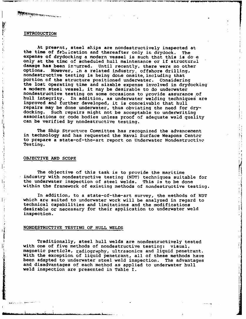
Using visual inspection on new welds, the diver can measure aweld profile usiiq connercially available gauges, Figure 2, whileundercut can be measured with a depth gauge.
Underwater photography is a well established art and can beused to provide a record and for more Qxtensive evaluatic: topside.
Magnetic Particle Inspection. Magnetic particle testing (MT)can be applied to ferrognetic materials such as ordinary carbonsteels. Of the sophisticated methods of NDT, magnetic particletesting is the most widely used for the inspection of cffshoredrilling rigs and is readily adaptable to underwater hull weldinspection.
The test consirts of three basic operationst
1. Establishing a suitable magnetic field in the object,where the magnetism must be in the correct direction, and thefield strength must be sufficiently strong.
2. Applying magnetic particles to the surface of the ubject
in the magnetized area.
3. Examining locations where the particles accumulate.
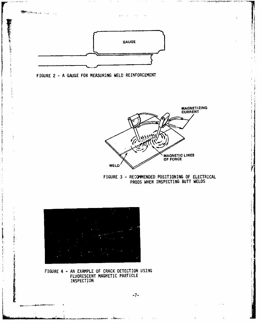
The method uses a pair of electrical prods positionedalongside the weld as shown in Figure 3. It is recommended thatthe prods be used ir. conjunction with lead shoes or other lowmelting point materials to suppress arcing and thus prevent burnmarks on the steel surface. The electrical current required forproper magnetization underwater is the same as that used whenworking in dry air, Table 2.4
Alternating current yokes and permanent magnets can also beused to induce the magnetic field but the surface should be groundsmooth for good contact.
Assuming the weld area has been cleaned of marine growth andthe diver has adequate visibility (Underwater lighting), ordinarymagnetic particles in a slurry in a squeezable container c.a beused to complete the inspection. The suspension is directed at theinspection area axA the results obtained are essentially the sameas when done topside using dust.
Superior results are obtained by using fluorescent particlesand illuminating the work area with ultraviolet light. Cracks arereadily detected, Figure 4. The ultraviolet lamps for use in thistype work have been designed with adequate electrical insulationand resistance to hydrostatic pressure and are commerciallyavailable.
If a record of the magnetic particle inspection is desired,the diver's equipment can include a television transmitter andvideo recording can be done topside. Alternatively photographscan be taken.
-6-
S• • • . • , •', R••:• '•J • • '• • .. . •"..........I .. ..... -. . . • . . . . . . ..
S~GAUGE
FIGURE 2 - A GAUGE FOR MEASURING WELD REINFORCEMENT
MAGNETIZINGCURRENT
MAGNETIC LINES
FIGURE 3 - RECOMMENDED POSITIONING OF ELECTRICALPRODS WHEN INSPECTING BUTT WELDS
FIGURE 4 - AN EXAMPLE OF CRACK DETECTION USINGFLUORESCENT MAGIMETIC PARTICLEINSPECTION
"-7-
iI
b£.•-

0.
m In
Li
0~
z~ v
w I I
z
-A J
z
CL

Radiographic Inspection. Radiography requires that the filmcassette and radiation source be positioned on opposite sides ofthe hull. The film cassette can be placed on the outside of thehull with the source of radiation inside, or this arrangement canbe reversed. There are advantages using the first arrangement and,if possibl, hull radiography should be done this way. However,if a physical obstruction prevents placement of the radiationsource inside the hull but there is room to position a cassette,then radiography can still be done using the other arrangement.
Radiography of steel welds of ordinary hull thicknesses isusually done with positive pressure cassettes containing leadintensifying screens. For the film cassette outside the hull,there is a need for watertight integrity and a polyethyleneenvelope will suffice. 5 The cassette package can be firmly fixedin place using permanent magnets with attached springs.
Because the water behind the cassette is a back-scatteringmedia, a sheet of lead, approximately 1/8" thick, should be fixedbehind the cassette to minimize film fogging. If the package istoo heavy for underwater work, neutral buoyancy can be achievedby placing a low-density material, such as styrofoam sheet, behindthe lead and within the watertight envelope, Figure 5. Simpleexperiments should enable a close approximation to neutralbuoyancy. Alternatively, the cass3tte package can be attached toa rope supported from topside and maneuvered into position by thediver using voice communication to coordinate the work.
Aligning the film cassette and the radiation source isdifficult to accomplish by coordinate measurements. Pinging isreported to be of considerable help in locating the approximate6Position , but precise positioning caii be done with ultrasonictransducers. For this, an Ultrasonic probe is fixed in positionac the desired location within the hull and the ultrasonicinstrument is set to receive with the entire range displayed.The diver then manipulates a second probe of the same frequency,but powered separately. When the two probes are aligned, a signalwill be received on the oscilloscope and, using voice communication,the diver is instructed to mark that location.
The thickness of the hull at the weld site can be determinedprecisely using an ultrasonic thickness gauge. This information,in conjunction with radiographic technique curves, affords theradiographer a means for correct exposure to obtain the desiredfilm d!ensity,.
Should" circunistances dictate that the source be placed out-side the liull, neutral buoyancy becomes more important. Theunderwater source of radiation will be an isotope rather than anx-ray machine as no commercial x-ray equipment has been modifiedto this purpose whereas th.s has been done with isotopes.7 Theisotope is invariably encased in lead of substantial thickness.in addition, rigid structure must be used to maintain the sourceto object distance, Figure 6. This structure can be either conicalor pyramidal in shape. If made watertight, either air or water canbe allowed to fill the space. Whichever system is used,
... .......

UA1LFIGURE 5 -WATERTIGHT AND NEUTRAL BUOYANCY
FILM CASSETTE PACKAGE FOR UNDER-WATER RADIOGRAPHY
RADITIO
LEADDAIO
F11LELEAD
LEAD HOOD
FIGURE 6 -SCHEMATICLEDHLINARRANGEMENT OF WELDTHE ISOTYPEHOLDER FOR______ ___
UNDERWATERRADIOGRAPHY
LEAKAGE I
-10-
consideration must be given to the diver's limitation to manipulatethe structu:7e into position, even if assisted by ropes maneuveredfrom topside.
Once the source is properly positioned, permanent magnets canbe :,sed to grip flanges and fix the structure in place. As before,the correct exposure time can be calculated, but it is difficultto control in-as-much as it depends upon the diver's promptaction in regard to cutting off the source or, having the cassettemoved from the field of continuing radiation.
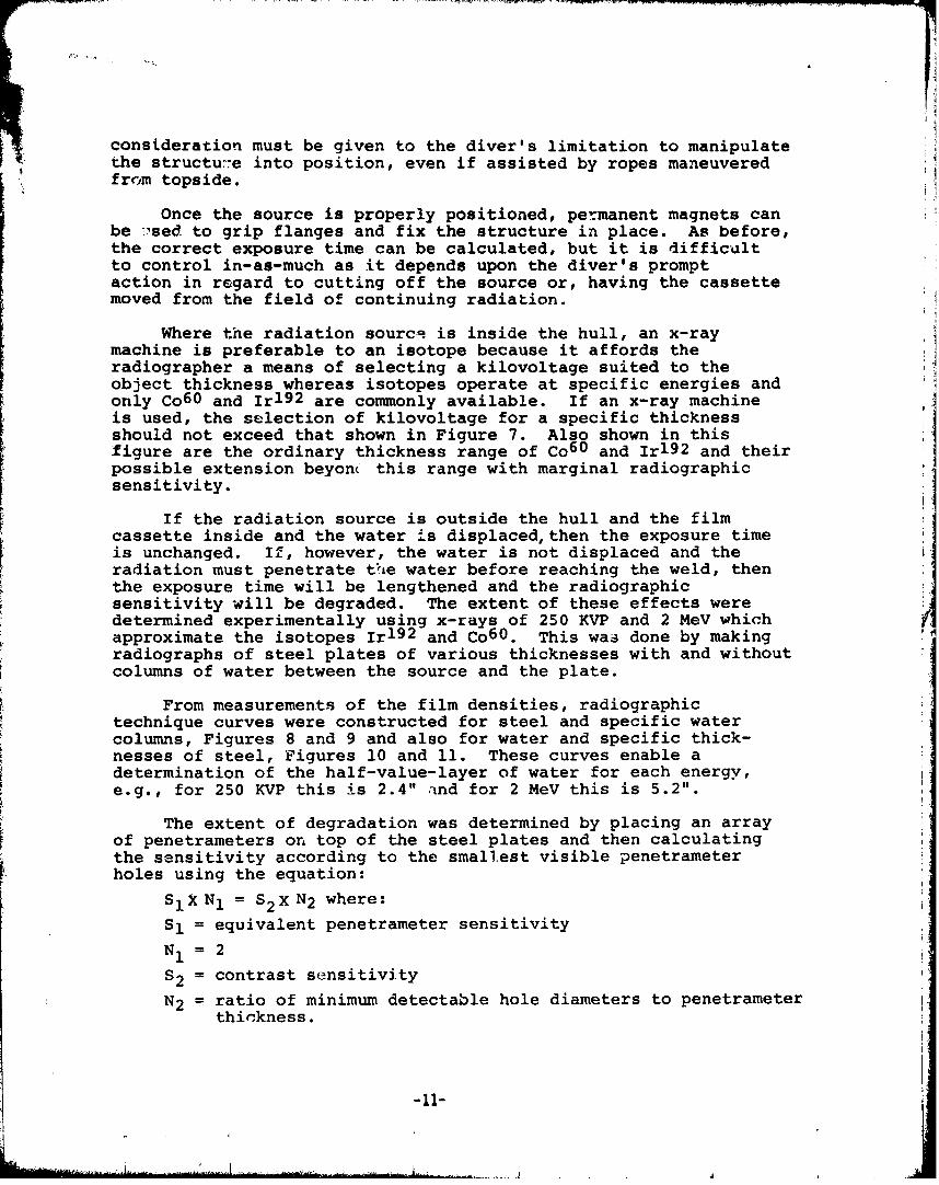
Where the radiation sourcq is inside the hull, an x-raymachine is preferable to an isotope because it affords theradiographer a means of selecting a kilovoltage suited to theobject thickness whereas isotopes operate at specific energies andonly Co6 0 and Ir 1 9 2 are commonly available. If an x-ray machineis used, the selection of kilovoltage for a specific thicknessshould not exceed that shown in Figure 7. Also shown in thisfigure are the ordinary thickness range of Co6 0 and Irl 9 2 and theirpossible extension beyon( this range with marginal radiographicsensitivity.
If the radiation source is outside the hull and the filmcassette inside and the water is displaced, then the exposure timeis unchanged. If, however, the water is not displaced and theradiation must penetrate th±e water before reaching the weld, thenthe exposure time will be lengthened and the radiographicsensitivity will be degraded. The extent of these effects weredetermined experimentally using x-rays of 250 KVP and 2 MeV whichapproximate the isotopes Ir 1 9 2 and Co 6 0. This was done by makingradiographs of steel plates of various thicknesses with and withoutcolumns of water between the source and the plate.
From measurements of the film densities, radiographictechnique curves were constructed for steel and specific watercolumns, Figures 8 and 9 and also for water and specific thick-nesses of steel, Figures 10 and 11. These curves enable adetermination of the half-value-layer of water for each energy,e.g., for 250 KVP this is 2.4" and for 2 MeV this is 5.2".
The extent of degradation was determined by placing an arrayof penetrameters on top of the steel plates and then calculatingthe sensitivity according to the smallest visible penetrameterholes using the equation:
SIX N1 = S 2 X N2 where:
S1 = equivalent penetrameter sensitivity
N1 = 2
S2 = contrast sensitivity
N2 = ratio of minimum detectable hole diameters to penetrameterthickness.
-11-

S ! I I CO 1 11T' I
O-192 II I I.- _ :i. _- . i l l lI II l!tll , 1!iltl .-
.h I E
0.1 0.150.2 0.3 0.4 0.6 0.86,.0 1.5 2 3 4 5 6 78 10 15 20
30,
20
10>
3w 7
6
3 - -
MAXIMUM PERMISSIBLE/I VOLTAGE1 MEV
700
o 4w
-JJ
M ACEDPTABLE REGIOEN
-12-100'
0.1 0.15 0.2. 0.3 0.4 0.6 0.81.0 1.5 2 3 4 5 6 78 10 15i 20STEEL SPECIMEN THICKNESS (INCHES?
•BROKEN LINE INDICATES MARGINAL SENSITIVITY
FIGURE 7 MAXIMUM VOLTAGE OR RADIOACTIVE ENERGY FOR•MINIMUM STEEL THICKNESS

M.lb
50Q1s 1111 1.01 . 20 L41i~ls f TIL c lsTIINISO TE W K
FI. RAIGRPIC EHIU.UVS FG AIGAHCTCNQECRE
FOR ~ ~ ~ .~ STE T20KPWIHVROSFRSTE T2MVWTHVROSTIK
THIKNSSS F WTE ITEPOSD ETEE 4ESE O WTERINEROSD BTWENTH
OPILUOENIIY 221150. * LA 1110FILTRA l, 11tD 1ý1140"'LK AT FILM.1(VECWIJO tMPRA1~I0E. I*P0AL FIL M, D EVrLOPINO EMPFIRAI URi ll0* Fl
s ~ ~ ~ i I.t I.A1.0 021 0 0 Is 1. I .0 L 2. 2.1
1WCX1~OP1111- INHESTHICiKNVSS Of WATERL - INCHES
FIG. 10 INRAEI RADIOGRAPHIC TECHNIQUE-CUIESRFIG. 9N RADIOGRAPHIC TCNQECREFXORSTREE AT 250 I(VP WITH VARIOUSAR FXOSRSEE AT 2 MeV WITH VEESARIOU THICKE-THCNSESOYAE INTERPOS EDiWAE BETWEEN THESSESIOF WATER ITROE BETWEEN THE SUC NTESOURCE AND OBJECT SUC N OBJECT
'lu13-

The results of this determination presented in Figures 12and 13 show a progressive degradation of radiographic sensitivitywith increased thicknesses of water between the source and object.
Ultrasonic Inspection. The adaption of ultrasonic inspectionto underwater work is simple in principle. The water serves js acouplant; and except for the transducer being made watertight 0 ,the technique is the same as that topside, Figure 14. Battery-powered ultrasonic inspection equipment is commercially availableiand if made watertight, can be carried by an inspector-diver.The technique is restricted to work near the surface unless theequipment housing is designed to withstand hydrostatic pressure.
A more practical approach is for the instrument to remaintopside while the probe is taken below by the diver. Throughvoice communication the diver can be instructed regarding rheposition and manipulation of the probe. A television transmitterattached to the tide of the diver's helmet with transLissiontopside permits the ultrasonic technician to see the probe move-ments as well as scope presentation and comprises a reasonableultrasonic inspection by remote control.
Before doing ultrasonic inspection, the area of probemanipulation must be cleaned of marine growth-to bare metal.
When ultrasonic inspection is done in air, cracks have anair interface with a reflection coefficient of almost 100%.In water, assuming the cracks come to the surface of the plateand water enters, the acoustic impedance mismatch is changed andsome of the ultrasonic energy is transmitted into the water.According to theory, the reflectivity coefficient is reduced to88%Ti Laboratory experiments confirm this approximate reduction.This difference is not considered cause for concern, because evensmall cracks are very efficient reflectors of ultrasound readilyfound by ultrasonic inspection.
The use of a very long cable increases the capacitance loadon the instrument pulser and necessitates a higher gain settingon the instrument to achieve the same sensitivity level used inultrasonic inspection topside with shorter cables. In addition,instrument calibration should be performed in a salt-water bath.However, the ends of the drilled holes in the test block, Figure15, should be sealed (epoxy cement is suggested) to maintain theair-steel reflectivity coefficient upon which the present weldinspection sensitivity level is baseý'.
A word of caution: Present procedure for inspecting buttwelds with ultrasonics assumes a flat surface (250 RMS or better)adjacent to the weld. Corrosion pits may be sufficiently numeroussuch that beam directivity is weakened by scatter of the soundwaves at the interfaces of the pits. The scatter may be severe tothe point where an expected signal is not obtained even though thetest is otherwise done correctly. There are no qLantitative dataavailable in this regard.
-14-

S- •- •- f2.2
2.0-
1.6 A 1 INC$ ST,5- - - - - - - --
S1.4 - -
0 Es S tsE%-2 %%CI
/~: ~1.2-
l'o -
(D -2.0. TFO - 32", AA FILM)". I I I I I I I I I
0 1 2 3 4 5 6 .7 8 9 10
THICKNEnS OF WATER - INCHES
FIGURE 12 - DEGRADATION OF RADIOGRAPHIC SENSITIVITY FOR STEEL AT 250 KViDUE TO INTERP'OSITION OF WATER BETWEEN THE SOURCE AND OBJECT
3.8F-
3.6
3.4- 00,
3.2-
~t 3.0 .'
2.8-
w -0.0-
2 2.,;,. ,.
1.2
(0 2.Q. TFD 6.0', AA FILM)__________________________ I ...j... J......J.._ .. ,L_ ...._ i Ji . I~* j I I I I I _I
"0 2 4 6 8 10 12 14 16 18 20 22 24 26 28 30 32 34 36 38 40
T-II CKNESS OF WA1 ER - INCHFS
FIGURE 1S - DEGRADATION OF RADIOGRAPHIC SENSITIVITi FOR STEEL AT 2MeVDUE TO INTERIPOSITION OF WATER BETWLIN THE SOURCE AND OBJECT
-1i

6 -r 1. m(/4i. HOG OE
II
6~ ~ ~~~~~~12 in.)m(36 n )TRUH OE
(I in.
II
I II II II II IImm.,25,5 ,1 m _.51 mm,, 51 mm 4...5.1 mm4.•L.1 mm,, 25.5 L•- mm I -2i:) -I (2 n) - -( in) - --(2 in ,) I (2 in.) Im m l|
(1 in. ) (1 n. )
°T T (3 in.)
38 mm 44 mm 51 mm 58 mm 64 mm 70 mm 3(1.5 in.) (1.75 in.) (2 in.) (2.25 in.) (2.5 in.) (2.75 in.) L
306 mm
K - - (12 in.)
MATERIAL - LOW CARBON STEELX- SURFACE FINISH 6.3 x 10⁻⁶ RMS MICROMETERS (250 RMS MICROINCHES)
FIGURE 15 - TYPICAL TEST BLOCK FOR CALIBRATION OF THEULTRASONIC INSTRUMENT
-16-
.7

Commercially available video-tape recorders can record theultrasonic oscilloscope presentation as well as an accompanyingvoice description. The video recorder can also record the diver's
Sfield of view as transmitted from the camera mounted on his helmet.These can be combined on one tape with playback on a split screen.
ADDITIONAL METHODS OF NONDESTRUCTIVE TESTING
Acoustical Hologr-ohy. Acoustical holography is analogous tooptical holograIphy wTt. qte exception that the object is on focusin a plane. The sy. 3m uses a matrix of ultrasonic transducers,focused to inspect each point of the weld volume1 0 , and act bothto send and receive. The returning signal is received separatelyat several transducers where signal amplitude, time and phase aremonitored in conjunction with an electronic gate. Then, thephased signals corresponding to the gate time are electronicallyprocessed to obtain a focused acoustic hologram.
As developed for underwater weld inspection, the diverpositions a probe, Figure 16, adjacent to the weld and the data aretransmitted to electronic equipment elsewhere (A lockout submers-ible at present, but could also be topside for hull weld inspection).There, the data are processed into an image on a plane; and bycombining this with a reference plane, it can be viewed as anoblique projection similar to three-dimensional viewing. The baseof the probe contains a television presentation of the constructedimage which helps the diver to manipulate the probe for bestposition.
The system appears capable of detecting cracks but has notbeen fully evaluated. While acoustical holography may be ofconsiderable use in surveillance work, especially in murky water,it seems unli.kely that it could be used as a primary inspectiontool for evaluating welds.
Magnetographic Method. The magnetographic method usesmagnetic tape instead of a powder or slurry of particles. 1 1
The tape is placed on top of the weld by a diver and then amagnetic field is induced in the work piece. Leakage flux atdiscontinuit sites are detected and recorded on the tapes.Evaluation i,' done topside with electronic processing to produceeither an oscilloscope display or a strip chart. The tape can bestored as a permanent record. This method has not gained wide-spread recognition and is not generally used.
A Harness of Ultrasonic Transducers. Currents or wave action,particularly near the surface may make it difficult or impossiblefor the diver to stay in a position which would make it difficultor impossible for him to do either ultrasonic or magnetic particleinspection. Recognizing the difficulties caused by turbulence,a British Corporation (BIX) has developed an ultrasonic inspectiondevice consisting of a linear array of ultrasonic shear wavetransducers which is incorporated into a flexible and magnetic pack.
-17-

Iii
"F�IGRE1�6DAOCTICA.LY fOLMOG AMPYR10 ElIlEOT FLEXIBLEAOIt© ARRIAYV
FO
-18- ,

The diver places this device atop the weld, slides it into properposition and magnets fix the pack firmly against the work surface.Topside, signals obtained from all transducers are displayedsimultaneously on an oscilloscope. If no signals are obtained,the weld is evaluated as free of cracks. If a signal is obtained,then the transducers are separately turned on and off to establishthe location and length of crack. The diver then moves the packinto a new position.
While this system provides reasonable assurance of crackdetection, no provision is made for to-and-fro motion of thetransducers and it, therefore, cannot be considered a suitabletool for primary weld inspection.
Television from Topside to Diver. A patented diver's helmetcontains a television receiver and a system of moveable opticalprisms which enables visual information from topside to be trans-mitted to the diver. 1 2 This can be blueprints of the work area orthe ultrasonic oscilloscope presentation. For the perzcn manip-ulating the probe, it is very helpfu to see the oscilloscopescreen and, in most cases, will result in better ultrasonicinspection.
COST •jNSIDERATIONS
The cost of performing nondestructive testing underwater isdifficult to determine because of the many considerations involved;such as cleaning of marine growth, depth and temperature of water,visibility, tidal currents, and the type of inspection. Theexperience of those working o.i offshore platforms in tLe North Seamay not be typical of what can be expected for ship hull inspectionin harbor, but little else is available for purposes of comparison.Det Norske Veritas reports that an inspection vessel with eightcrew members, sixteen cleaning divers and sixteen inspection diverscan test two one-meter welds per day.13
Although these figures undoubtedly represent a situation ofextreme difficulty, nonutheless, they suggest a very high cost forunderwater inspection.
After inspection, treas cleaned to bare metal will require arestoration of the protective coating. Epoxy paints can beapplied underwater by brush rolling and other means, but theadditional expense of doing this must be considered a part of thecost of inspection.
-19-
CONCLUSIONS
With the exception of liquid penetrant, the ordinary methodsof nondestructive testing (visual, magnetic particle, ultrasonicsan4 radiogrrphy) used topside to inspect steel butt welds can beextended to underwater applications.
Performing NDT underwater will be expensive - far more sothen the cost of such work topside - but, as has been demonstratedin the related industry of offshore drilling, it can be done.
Ii
S-20- I

REFERENCES
1. Busby, R. Frank. Underwater Inspection/Testing/Monitoringof Offshore Structure, Feb 1978, pp. 65
2. Busby, R. Frank, Underwater Inspection/Testing/Monitoringof Offshore Structure, Feb 1978, pp. 75
3. Routine Inspection of Subsea Structures is the Diver'sBread and Butter; Offshore Engineer, May 1978.
4. Recommended Practice for Underwater Inspection (IIW
Document V-624-78, Johannes Hatlo, Det Norske Veritas.
5. Alan Taylor, Underwater Testing, Marine rechnology(Germany) Dec 1971, pp. 251-2.
6. Ship Underwater Maintenance, Evaluation and Repair,NAVSEC Report 6136-77-9, Feb 1977.
7. E. L. Criscuolo, D. P. Case and D. Polansky, "TheInvestigation of Radio Isotopes for the Inspection of ShipWelds," SSC-l10, Feb 1958, pp. 17
8. J. Walter, R. Sletten, "Underwater Inspection of OffshoreStructures," Det Norske Veritas, Eighth World Conferenceon Nondestructive Testing, pp. 6
9. Nondest..uctive Testing Handbook, 1959, Volume 2, pp. 43"13
10. Alain G. Stankoff, and Dale H. Collins, "Application ofAcoustical Holography to Inspection of Offshore Platforms,"Offshore Technology Conference, Houston, TX, 1978
11. The Underwater Inspection of Fixed Offshore Platforms,LERE Harewell, Jul 1975, pp. 51
12. Sylvester Underseas Inspection, Rockland, MA.
13. R. Sletten, "Underwater Inspection of Offshore Structures,"Eighth World Conference on Nondestructive Testing.
14. Ship Underwater Maintenance Evaluation and Repair, NAVSECReport 6136-77-9, Feb 1977, pp. E-25
I
-21- I[

[L
BIBLIOGRAPHY
1. Criscuolo, E. L., et al., "Manual of Isotope Radiography,"Ship Structure Committee, SSC-121, May 1960.
2. Criscuolo, E. L., et al., "The Investigation ofRadioisotopes for the Inspection of Ship Welds," ShipStructure Committee, SSC-1I0, Feb 28, 1958.
3. Bainton, K. F., et al., "The Underwater Inspection of FixedOffshore Platforms, A Review and Assessment of Techniques,"AERE-R8067, RR-SMT/R7403, Materials Physics Division AEREHarwell, Oxforshire, England, Harwell United KingdomAtomic Energy Authority, Jul 1975.
4. Silk, M. G., et al., "The Continuous Monitoring of FixedOffshore Platforms for Structural Failure, A Review andAssessment of Techniques," AERE-R8055, Materials PhysicsDivision AERE Harwell, Oxfordshire England, Harwell UnitedKingdom Atomic Energy Authority, Sep 1975.
5. The Ronald Press Company, Nondestructive Testing Handbook,New York, NY, 1959.
6. American Bureau of Shipping, Rules for NondestructiveIrnspection of H-ull Welds, New York, NY, 1975. l•
7. American Welding Society, Inc., Welding Inspection,New York, NY, 1968.
8. Hirschfield, J. J., and O'Connor D. T., "Development ofUnderwater Cobalt Camera," U. S. Naval Ordnance Laboratory,White Oak, MD, Nov 5, 1951.
9. Youshaw, R. A., "A Guide for Ultrasonic Testing andEvaluation of Weld Flaws," Ship Structure Committee,SSC-213, 1970.
10. Cook, W. V., "Using Ultrasonic To Test Offshore Stiuctures,"Ocean Industry, Oct 1970, V. 5, No. 10, Page 15 & 16.
11. Peters, V. "NDT for Offshore Drilling Platform Structure,"Welding end Metal Fabricatior, Jul 1973, V. 41-7.
12. Taylor, A., "Underwater Nondestructive Testing," MarineTechnology (Germany), Dec 1971, V. 2-6, Page 251 & 252.
13. Goodfellow, R. and Bourne, M. J., "Underwater Inspectionof Deepwater Facilities," Petroleum Engineer, Jun 1976,V. 48-7, Page 11.
-22-

14. Irish, J.,, -Plugging the Holes in Subsea Checkups,"Offshore Engineer, Jul 1976, page 23.
15. Attfield, K., "Putting Test Cnu3 Where It Belurics,"Offshore Engineer, Jul 1976, pagre 25.
16. Youshaw, fl. A., and Criscuolo, B. L., "A Guide for theaondestructive Testing of Non-EutL Welds in CommercialShips Part 1," Naval Ordnance Lab., White Oak, MD,Dee 31, 1974.
17. Busby, Frank, and R. Associates, "Underwater Inspection/ I
Testing Monitoring of Offshore Structu1res,"' NOAA/Officeof Eiigineezing, Rlockville, MD, -Ffzgb 1978.
18. Stankoff, Alain G., and Collins, Dale H., "Application ofAcoustical Holography to the Inspection of offshoreIPlatforms," offshore Technology Conference, Houstoa~, TX,
19. "Ship Underwater Maintenance, Elvaluation & Repair, (Sumer)Master Plan," Naval Ship Engineering Center,Report 6136-77-9. Feb 1977.
20. Hatlo, Johannes, "'Recomnmended Practice for UnderwaterInspection," Document V, 1978.
21. Hages, D. Michael, "Underwater inspection of OffshoreStructures - Methods and Results," Offshore TechnologyConference OTC 1565, 1972.
22. Sletten, R., et al., "Underwater Inspection of OffshoreStructures," Det Norske Veritas, Eighth World Conferenceon Nondestructive Testing.
23. Tainehiro, Masaki, et al., "Development of UnderwaterWelding Technique," Eighth Meeting of the Marine Facilities,Panel of the US - Japan Natural Resources, Sep 9, 1978.
24. Thornton, D., "A Case Study of the Forties Field,"Northern Offshore, No. 7, 1976.
*U.S. GOVERNMENT PRINTING OFFICE, 1979-311-586/249
-23-

ISHIP RESEARCH COWITIEEMaritime Transportation Research Board
Natioial Acadeity of Sciences-National Research Cour 1l
I : .~
k The Ship Research Committee has technical cognizance of theinteragemcy Ship Structure Committee's research program:
Mr. 0. H. Oakley, Chairmano Consultant, Mokezn, VAMr. M. D. Burkhart, Naval Oceanography Division, Department of the Navy,
Iaewhigto, D.C.Dr. J. N. Cordea, Senior Staff Metallurgist, ATECO INC., Middletoon, OHMr. D. P. Courtsal, Vice reasident, DRAVO Corporation., Pit-ýeburgh, PA14;^' W. J. Lane, Consultant, Baltimore, MDMr. A. C. McClure, Alan C. McClure Axeooiates, Inc., Houston, TXDr. W. R. Porter, Vice •roe. for Aoadmi Affire, State Uniu. of N.Y.
Maritime CollegeProf. S. T. Rolfe, Civil Eng-,nooring Dept., Univer,# ty of neasMr. R. W. Rumke, Executive Seareteta2, Ship Research Comnittee
The. Ship Materials, Fabrication, & Inspection Advisory Groupprepared the project prospectus, evaluated the proposals for this project,provided the liaison technical guidance, and reviewed the project reportswith the investigator:
Dr. 3. N. Cordea, Chairman, Senior Staff MetalZlugiet, ARMCO INC., Middletown, OHMr. W. C. Brayton, Aset. to Gener•l Manager, Bethlehem Steel Corp., Sparrow. Point,tD"Mr. T. E. Koster, Naval Ar'ohitet, AMOCO InternationaZ Oil Co., Chicago, ILDr. W. C. Leslie, Dept. of MateriaZe A Net. Engrg., Univ. of Michigan, Ann Arbor, MIDr. H. 1. Mcdenry, Cryogenics Division, National Bureau of Standards, Boulder, CoMr. P. W. MarshalI, Senior Staff Civil Aigr.., SHEL OIL CO.. Houston, TXProf. P. F. Packman, C'nn, Dept. of Civil & Mech. tngrg., Southern Methodist Univ.
Dalae, TXProf. G. C. Sih, Tnst. of racture 4 Solid Mechanics, Lehigh Univ., Bethlehem, PA
:' ~4•4444.4A.,
SHIP STRUCTURE COWfITTEE PUBLICATIONS
Thee doownents are distributed by the National TechnicalInforimtion Service, Springfield, VA 22161. These doc-u'unte have been annowced in the Clearinghouse JournalU. S. Government Research 4 Development Reports (USGRDR)under the indicated AD nwnbers.
SSC-279, Modified Radar and Standard Tucker Wavemeter SL-7 Containership Databy J. F. Daizell. 1978. AD-A062393.
SSC-280, Results and Evaluation of the SL-7 Containerahip Radar and Tucker Wave-meter Data by J. F. DaIze11. 1978. AD-A062392.
SSC-281, Bibliography for the Study of PropeZZer-Induced Vibration in HullStructural Elements by 0. H. Burnside and D. D. Kana. 1978. AD-A062996.
SSC-282, Cornp.-Ion •f Stresses Calculated Using the DAISY System to ThoseMeasured on the SL-7 Containership Program by H. Y. Jan, K. T. Chang,and M. E. Wojnarowski. 1979. AD-A069031.
SSC-283, A Literature Survey on the Collision and Grounding Protection of Shipsby N. Jones. 1979. AD-A069032.
SSC-284, Critical Evaluation of Low-bnegy Ship ColZision-damzge Theories andDesign Methodologies - Volume I - Evaluation and Recornendationar byP. R. Van Mater, Jr., and J. G. Glannotti. 1979. AD-A070567.
SSC-285, Critical EvaZuation of Lowuergy ship Cozzision-Dwnrge Theories anODesign NethoZZogies - Volume II - Literature Search and Review byP. R. Van Mater, Jr., and J. G. Giannottl. 1979. AD-A070568.
SSC-286, Results of the First Five "Data Years" of Extreme Stress Scratch GaugeData Collection Aboard Sea-Land's SL-7'e by R. A. Fain and E. T. Booth.1979. AD-A072945.
SSC-287, 9=dination of Service and Stress Data of Three Ships for Developmentof Bull Girder Load Criteria by J. F. Daizell, N. M. Maniar, andM. W. Hsu. 1979. AD-A072910.
p:
SSC-288, The Effects of Varying Ship Hull Proportions and Hull Materials on HullSFleibility Bending and Vibratory Stresses by P. Y. Chang.1979.
SSC-289, A Method for Economric fr de-Offs of Alternate Ship Structural Materialsby C. R. Jordan, J. B. Montgomery, R. P. Krumpen, and D. J. Woodley.1979.
SSC-2909 Significance and Control of Lamiellar Tearing of Steel Plate ir theShipbuilding Industry by 3. Sonmella. 1979.
SSC-291, A Design Pmoedure for Minimixing PropelZer-Induced Vibration in HullStructural Elements by 0. H. Burnside, D. D. Kana. and F. E. Reed.1979.
SSC-292, Report on Ship Vibration S7ij w '78 - Sheraton National HoteZ,Arlington, VA. by E. Scott- ion. 1979.


![Defect detection in FSW steel plates by NDT methodsijrpublisher.com/gallery/361-december-2018.pdfInspection of Hull Welds’. Anish Kumar et al [3] in thePaper titled “Development](https://static.fdocuments.net/doc/165x107/5f96529d6980c142dd4f6526/defect-detection-in-fsw-steel-plates-by-ndt-inspection-of-hull-weldsa-anish-kumar.jpg)