Understanding and Mitigating the Impact of Interference … · Understanding and Mitigating the...
29
Understanding and Mitigating the Impact of Interference on 802.11 Networks By Gulzar Ahmad Sanjay Bhatt Morteza Kheirkhah Adam Kral Jannik Sundø 1
Transcript of Understanding and Mitigating the Impact of Interference … · Understanding and Mitigating the...

Understanding and Mitigating the Impact of Interference on
802.11 Networks
By
Gulzar Ahmad
Sanjay Bhatt
Morteza Kheirkhah
Adam Kral
Jannik Sundø
1

Outline
• Background
• Contributions
1.Quantification & Classification of interferers
2.Model capturing limitations
3.Scheme that can withstand strong interferers
• Evaluation
• Critical Appraisal
• Related work
• Question(s) time
2

• Wireless transmission and RF(Radio Frequency) Interferers:
Vulnerable to RF
FCC, ITU regulations, users of ISM band and their co-existence
Limit transmission power
Force nodes to spread signals
Does not prevent a range of interference
• Interferes:
Cheap 802.11 devices and 2.4 GHz ISM band
Wireless jammers
Zigbee
Cordless phone
Disruption in 802.11 operation
802.11 equipment and patterns of weak or narrow-band interference
Victim’s 802.11 signals and weaker interfering signal
Background
3

• Types of interferers
Selfish Interferers
They run own protocol for their own benefit
Malicious Interferers
They deny service and do not do any useful work
Even highly attenuated signals causes severe losses at the receiver
• Current mechanisms to mitigate noise and interference
A MAC protocol to avoid collisions
Lower transmission rates that accommodate lower SINR ratios
Signal spreading which tolerates narrow-band fading and interference
PHY layer coding for error correction
• Failure of current mechanisms
Do not help due to reception path limitations
Fail to tolerate interference gracefully
Background Continued
4

Background – detecting free medium
• Device determines free medium in one of three
ways:
1. Energy above an Energy Detect (ED) threshold
means busy medium
2. Valid 802.11-modulated signal detection means
busy medium (normally used)
3. Both 1. and 2.
5

Timing Recovery Interference
• Receiver uses SYNC pattern from preamble to sync to
transmitter's clock
• Interferer transmits SYNC pattern continuously causing receiver to
fail to lock onto transmitter’s clock
• Receiver records only energy detection events, but not packets6
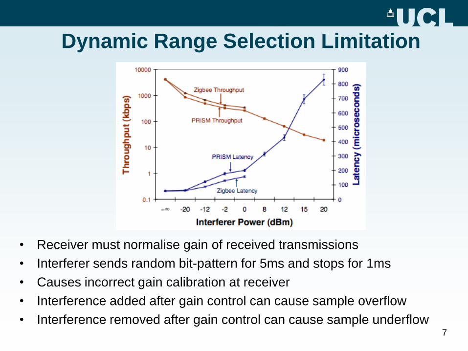
Dynamic Range Selection Limitation
• Receiver must normalise gain of received transmissions
• Interferer sends random bit-pattern for 5ms and stops for 1ms
• Causes incorrect gain calibration at receiver
• Interference added after gain control can cause sample overflow
• Interference removed after gain control can cause sample underflow7

Header Processing Interference
• Start Frame Delimiter field signifies that PLCP header is about to be sent
• If interferer continuously transmits SFD field, receiver believes following
bits are the PLCP header
• Causes header to be assembled from wrong samples, resulting in CRC
header failure
8

Impact of Interference on 802.11g/n
• 802.11g and 802.11n are different from 802.11b
• 802.11g does not use a Barker Correlator and uses OFDM
• 802.11n uses spatial coding techniques
• How does interference affect them?
• Authors subjected g and n to similar interference patterns
• Result: still substantial throughput loss
• Cause: same receiver limitations (gain adjustment done once per packet and limited dynamic range)
9
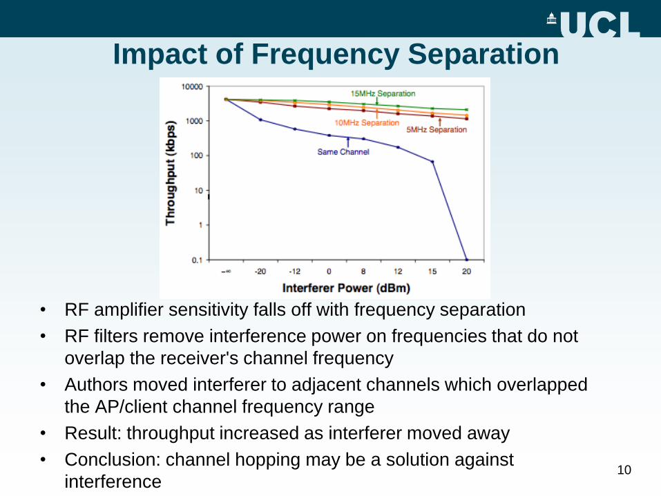
Impact of Frequency Separation
• RF amplifier sensitivity falls off with frequency separation
• RF filters remove interference power on frequencies that do not
overlap the receiver's channel frequency
• Authors moved interferer to adjacent channels which overlapped
the AP/client channel frequency range
• Result: throughput increased as interferer moved away
• Conclusion: channel hopping may be a solution against
interference10

Why do we need better Model of Interference Effects?
• Standard SINR model– Basic idea: compute receiver difference between
• signal power
• combined interference and noise power
• Doesn’t account for limitations of commodity NICs (covered earlier)
• Example: standard model predicts high probability of receiving packets if signal power is >10dB than interference at receiver– Actual observation is high packet loss
11
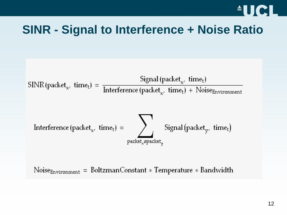
SINR - Signal to Interference + Noise Ratio
12

Advanced SINR
•Processing Gain
• Barker Coding (used in DSSS)
• Adds redundancy => We can do error checks and correction
• Adds 10.4dB => Signal can be 0.4dB weaker than interferer
•Automatic Gain Control
• Ensure signal is in processing range
Attenuate strong signal: -30dBm
Minimum SINR: -0.4 dB + 30 dB = 29.6 dB
13

Advanced SINR
• Non-linear Sensitivity
•Receiver's amplifier attenuate interference away from
the centre
• [f1,f2] frequency range that receiver and interferer overlap
• Sensitivity increases with frequency separation
• -10dB @ 2MHz => SINR increase by 10dB for 2MHz displacement
• -30dB @ 5MHz => SINR increase by 30dB for 5MHz displacement
14

What do we expect?
• Throughput to decrease linearly with interference
• There are lots of options for 802.11 devices to tolerate interference Bit-rate adaptation
Packet size variation
Forward Error Correction (OFDM,BPSK,QPSK used this technique)
Spread-spectrum processing
Transmission and reception diversity
Interferer power
(log-scale)
Th
rou
gh
pu
t (l
inear)
15

What we see!
• Effects of interference
more severe in practice
• Caused by hardware
limitations of commodity
cards, which theory
doesn’t model Interferer power
(log-scale)
Th
rou
gh
pu
t (l
inear)
16

Impact of 802.11 parameters
• Rate adaptation, packet sizes, FEC, and varying CCA thresholds and mode do not help
0.1
1
10
100
1000
10000
−∞ -20 -12 -2 8 12 15 20
Interferer Power (dBm)
Thro
ughput
(kbps)
1Mbps
100-byte packets,
11Mbps
2Mbps5.5Mbps
11Mbps
11Mbps, PBCC
5.5Mbps,
PBCC
CCA Mode 1,
11Mbps
With and without
FEC
Rate adaptation
Changing CCA mode
Changing packet size
17

New Scheme Design
18
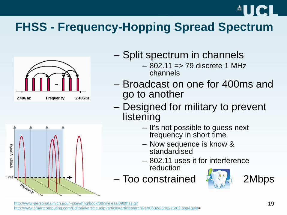
FHSS - Frequency-Hopping Spread Spectrum
– Split spectrum in channels– 802.11 => 79 discrete 1 MHz
channels
– Broadcast on one for 400ms and go to another
– Designed for military to prevent listening
– It's not possible to guess next frequency in short time
– Now sequence is know & standardised
– 802.11 uses it for interference reduction
– Too constrained 2Mbps
http://www-personal.umich.edu/~csev/hng/book/08wireless/090fhss.gif
http://www.smartcomputing.com/Editorial/article.asp?article=articles/archive/r0602/25r02/25r02.asp&guid=19

20

DSSS - Direct Sequence Spread Spectrum
• Barker coding
• Oops, Shanon's theorem:
– 11Mbps eats 22Mhz
– Channel overlapping
– Need 25Mhz separation
http://www.wirelessnetworkproducts.com/index.asp?ID=73&PageAction=Custom
http://www.smartbridges.com/education/print-ready.asp?id=395
21
Rapid Channel Hoping + DSSS
• CH+DSSS Goals
– Withstand malicious interferers => CH
– Efficient
– Minimise compatibility issues
• Balance between:
– Transmission time: 10ms
– Switching time: 250μs – 500μs => 2.5% overhead
• Channel Hopping
– Sequence - MD5 Hash Chain
22

Evaluation 1000 kbps = 1 Mbps
• No interference - benchmark [not shown on graph]– No channel hopping (CH) – UDP achieves 4.4Mbps
– With CH – UDP achieves 3.6Mbps
• With interference– No CH
• UDP degrades from around 30 kbps (big decrease)
– CH• UDP degrades from around 3,000 kbps (3 Mbps)
• TCP fails completely with no CH
• TCP gets around 70% of UDP performance with CH23

Evaluation
• As interferer power increases– Average loss rate stays less than 4%
– Number of packets requiring one retransmit goes up
– Number of packets requiring more than one retransmit stays fairly constant
• Reasons– Increase in number of single retransmits due to interferer increasing leaking
into other bands
– Increase in latency due to deferrals and losses during times when interferer successful
24

Evaluation
• Throughput (UDP)
– falls linearly with more PRISM interferers
– more gradual decrease with other type of interferers – narrowband
• TCP throughput 20%-40% worse
• Loss rates (not shown on graph) for different types of interferers
under 5% due to CH - slots quickly found 25

Critical Appraisal
• Attacker can use 11 interferers
• Interferer can prevent clients from connecting to AP,
hence no channel hopping
• Cryptographic security of the MD5 checksum
• Channel dwell time
26
Related work
• RF interference and jamming (narrow-band
jamming, demodulator interference)
– We expose additional vulnerabilities in receive path
• 802.11 DoS (e.g., CCA, association, and
authentication attacks)
– We target PHY instead of MAC
• Slow channel hopping (e.g., SSCH, MAXchop,
802.11 FH)
– Rapid channel hopping uses both direct-sequence
and frequency hopping to tolerate agile adversaries
27

Questions?
28

Thank you.
29