Understanding and Eliminating RF Interference
20
1 Understanding and Eliminating RF Interference Jim Brown K9YC Audio Systems Group, Inc. http://audiosystemsgroup.com Basic Interference Mechanisms • Audio cables are antennas – Pin 1 problems – Shield-current-induced noise (SCIN) – Inadequate filtering of equipment ins and outs – Audiofool “DC-to-daylight” design philosophy • Shield current can excite all of these Sources of Shield Current • Noise voltage on “ground” at ends of cable – Filter capacitors on the power line – Leakage capacitance in power transformers – Current flowing in ground unrelated to audio system (motors, lighting equipment, etc.) – Wiring errors • Induced by magnetic fields – Double-bonded neutrals – Big transformers and motors • Radio transmitters (antenna action) The Pin 1 Problem • Current flows on cable shields – Hum, buzz, RF • If shield goes to shielding enclosure, current stays outside the box • If shield goes to the circuit board, current goes inside the box! The Pin 1 Problem The Pin 1 Problem
Transcript of Understanding and Eliminating RF Interference

1
Understanding and Eliminating RF Interference
Jim Brown K9YCAudio Systems Group, Inc.
http://audiosystemsgroup.com
Basic Interference Mechanisms• Audio cables are antennas
– Pin 1 problems– Shield-current-induced noise (SCIN)– Inadequate filtering of equipment ins and outs– Audiofool “DC-to-daylight” design philosophy
• Shield current can excite all of these
Sources of Shield Current• Noise voltage on “ground” at ends of cable
– Filter capacitors on the power line– Leakage capacitance in power transformers– Current flowing in ground unrelated to audio
system (motors, lighting equipment, etc.)– Wiring errors
• Induced by magnetic fields– Double-bonded neutrals– Big transformers and motors
• Radio transmitters (antenna action)
The Pin 1 Problem• Current flows on cable shields
– Hum, buzz, RF• If shield goes to shielding enclosure, current
stays outside the box• If shield goes to the circuit board, current
goes inside the box!
The Pin 1 Problem The Pin 1 Problem

2
It’s in Unbalanced Circuits Too! It’s in Unbalanced Circuits Too!
Some Classic Pin 1 Problems
A Classic Pin 1 Problem An Effective (but Ugly) Fix

3
RF in the Shack is a Pin 1 Problem
• Nearly all ham gear has pin 1 problems– Mic inputs– Keying inputs– Control inputs and outputs
• Nearly all computers have pin 1 problems– Sound cards– Serial ports
Great Radio, Has Pin 1 Problems
Ten Tec Omni V
A Pin 1 Problem? Maybe Where are the Chassis Connections for this laptop’s sound card?
• Hint: It isn’t an audio connector shell! – That metal is a shield, but not connected to
connectors!– And the cover is plastic too!

4
Where are the Chassis Connections for this laptop’s sound card?
Yes, it’s the DB9 and DB25 shells!
Too Much Bandwidth• Wiring often puts RF on equipment inputs
(and outputs)• Equipment must be able to reject it!• Audio spectrum ends at 20 kHz
– Filters produce phase shift– Phase shift in multiple stages adds up– Small rolloffs (0.5 dB) add up– So 100 kHz is a reasonable cutoff– Going beyond 200 kHz is CRAZY!
The AudioFool Viewpoint• The Myth: “We can hear stuff above 20 kHz”• Reality: Some distortion mechanisms DO
produce audible artifacts from ultrasonic signals, but we hear the problems, not the signals!
• Intermodulation distortion (40 kHz – 30 kHz = 10 kHz)
• Slew rate limiting within electronics of ultrasonic output of a mic (or of square waves from a test generator)
Golden Rules to Avoid RFI
• All wiring can act as an antenna– It can receive current if RF is present– It can transmit RF if RF current flows on it
• Radio signals cause current to flow• Don’t let that current cause problems
Golden Rules to Avoid RFI• Fix pin 1 problems• Fix equipment with excessive
bandwidth– Add low-pass filters at inputs– Input transformers are inherently
good low-pass filters (Jensen, Lundahl)
– Faraday shield blocks common mode
Differential Mode Response of Jensen Isolation Transformer
Approximates a 3-pole, 300 kHz low pass filter!
5
Golden Rules to Avoid RFI• Loudspeaker Cables
– Always use TWISTED PAIR– Shielding is not important– Exotic cable is a waste of money
• Mic and Line level Cables– Avoid drain wires in shields– Use braid shielded cable – Use twisted pair (tighter twist helps too)
Golden Rules to Avoid RFI• Maximize audio levels on cables
– Run output stages near their maximumlevels
– Set input gains near their minimumlevels
Critical Product Specifications• Maximize input level
– How much signal does it take to clip the input stage?
• Maximum output level– How much can the box put out cleanly?
Output Stage
Input Stage
Noise = 500 µV
+250 mV avg1 V peaks)
Signal to noise = 54 dB
Gain at minimum
Output Stage
Input Stage
Noise = 500 µV
+50 mV avg200 mV peaks)
Signal to noise = 40 dB
Gain at maximum
Output Stage
Xmtr Mic Input
RF from Antenna
Matching a Computer Output to a Transmitter Input
0.5 V 26 mV
The pad attenuates the computer output to match the mic input. It also attenuates any hum, buzz, or RF picked up on the input wiring.

6
Golden Rules to Avoid RFI• RFI often enters equipment (and systems)
by more than one path. • Always assume that there are other paths! • Take a methodical approach. Don’t give
up when one “right” technique doesn’t fix it – keep on doing other “right” things. The “right” techniques really are right!
Golden Rules to Avoid RFI• And when that isn’t enough:
Ferrites can block the current! An AM Broadcast Choke
14 turns of mic cable around this ferrite can kill AM broadcast RFI
This “Clamp-On” forms a choke that can kill interference from FM and TV
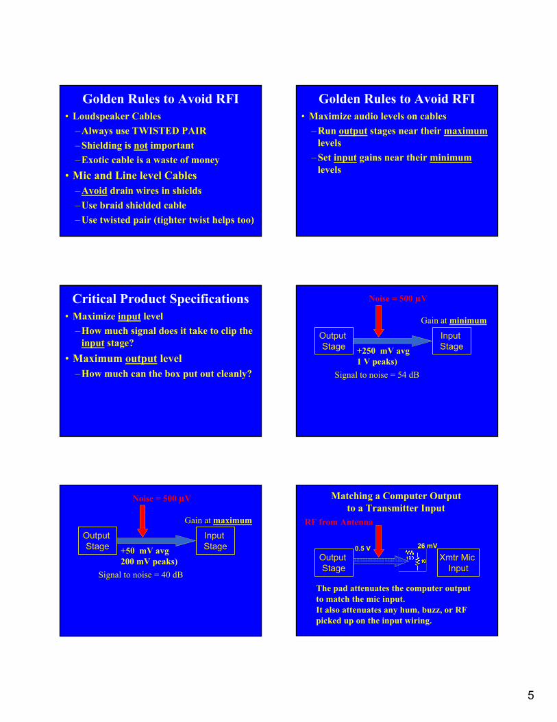
What’s a Ferrite?• A ceramic consisting of an iron oxide
– manganese-zinc – MF, HF (AM broadcast, hams)– nickel-zinc – VHF, UHF (FM, TV, cell phones)
• Has permeability much greater than air– Better path for magnetic flux than air– Multiplies inductance of a wire passed through it
• Is increasingly lossy at higher frequencies• Does not affect audio
7
Permeability• Symbol is µ
– µ0 is permeability of free space (air, aluminum)– µr on data sheets is usually the relative
permeability, referenced to free space– Subscript r usually omitted µ
• Typical µ values – Steel 1,000– Stainless steel 500– Mu-metal 20,000– Ferrites 100 – 3,000
A (too) simple equivalent circuit of a wire passing through a ferrite
Rs and Xs vary with frequency! A Ferrite Optimized for UHF
3 turns
Z for multi-turn chokes on a 2.4” toroid(Fair-Rite #78)
ZN = N2 * Z1
A material useful on the AM broadcast Band #78 material useful on the AM broadcast Band
RS for multi-turn chokes on a 2.4” toroid
RN = N2 * R1

8
5 turns
XS for multi-turn chokes on a 2.4” toroid
XN = N2 . X1
#78 material useful on the AM broadcast Band
5 turns Parallel Resonance!
What Causes this Resonance?The ferrite material (the mix), andThe physical dimensions of the ferrite core.• There is a finite velocity of propagation within
the ferrite • There are standing waves within the core when
the cross-section is a half-wavelength• Frequency of the resonance depends on:
– Velocity of propagation (depends on the “mix”)– Dimensions of the cross-section of the flux path
Rs and Xs vary with frequency!
Same material, different lengths!Longer
Shorter
A Ferrite Mix Optimized for UHF

9
Audio Cable is Lossy at RF• RF is detected within equipment.• RF that gets in at a distance will be
attenuated by the cable. • It’s RF that gets onto the cable close to
the equipment that matters most.• So put the ferrite choke very close to
the equipment that is detecting the RF
Let’s Test Our Equivalent CircuitIt looks OK for the #78 material at lowfrequencies, but look at high frequencies –there is another resonance up there!
LD and CD describe the dimensional resonance.RD accounts for the losses in the ferrite. We need a more com-plex equivalent circuit.
LC is the inductance of the coilCC is the stray capacitance of the coilRC is the resistance of the wire.LC and CC is the resonance that moves!
WireFerrite
General Equivalent Circuit Impedance of Multi-turn Chokes on #78 2.4” Toroid
Impedance of Chokes on #43 2.4” ToroidThere’s only one resonance here – the coil
Impedance of Multi-turn Chokes on #43 2.4” Toroid

10
Why no Dimensional Resonance?The #78 is MnZn, while this one is NiZn• VP in #43 is much higher, so dimensional
resonance would occur at VHF rather than MF • At VHF, there is so much loss that it damps the
standing waves that would produce dimensional resonance
Impedance of Multi-turn Chokes on #61 2.4” Toroid
Data Sheets Show the Resonance
Resonance
Impedance of Multi-turn Chokes on #77 2.4” Toroid
Impedance of Multi-turn Chokes on #43 2.4” Toroid Impedance of Multi-turn Chokes on #31 2.4” Toroid
11
Impedance of Multi-turn Chokes on #61 2.4” Toroid
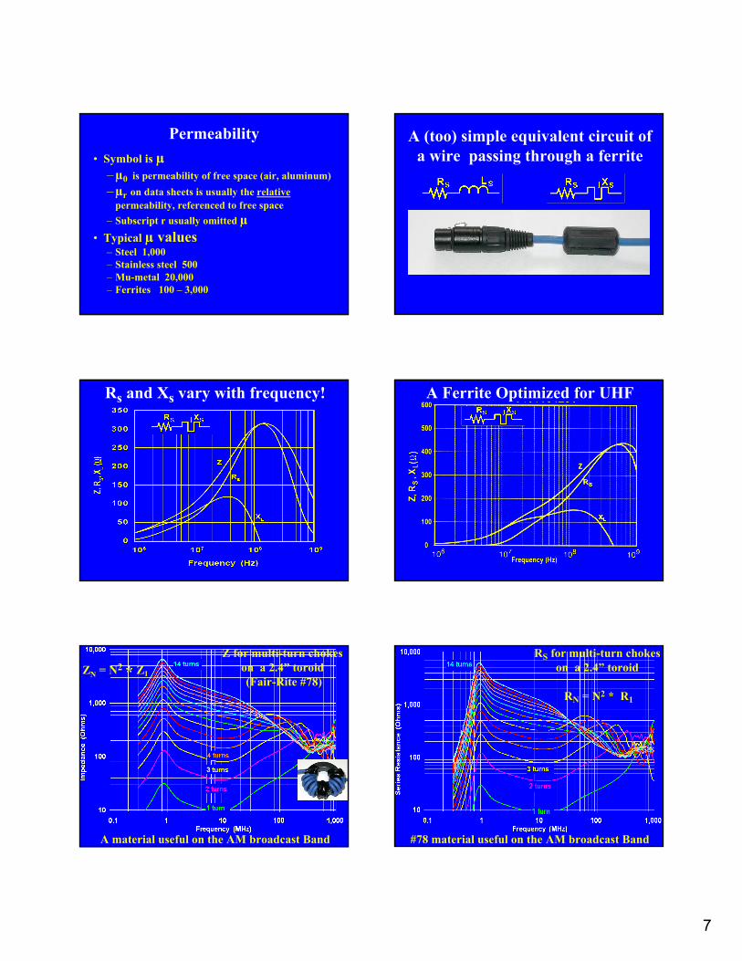
A Simple Bead (#43) works for VHF
A Multi-turn Choke (#43) is needed for lower frequencies
Different Tools for Different Problems
So How do We Use These Tools? A Choke Applied to a Mic Cable
It’s a voltage divider!
The Choke can Resonate with the Antenna
A short antenna will look capacitive.XL can cancel some or all of XC antCurrent will increase, unless RS limits it – so, for effective suppression:
RS should always be large!
Equipment Not Well Grounded
Voltage divider less effective!

12
Criteria for Good Suppression• Choke should be predominantly resistive• With voltage divider (capacitor across input)
– A few hundred ohms can be very effective• No voltage divider (brute force)
– At least 700 ohms needed, more is better• 700 – 1,000 ohms RS should be a “minimum”
design goal
Capacitance Can Help a Lot • Outside the box, we’re stuck with what the
designer provided, so a big ferrite is needed• Inside the box, we can use a smaller ferrite
part if we provide the capacitor
You May Not Need an Elephant Gun• Most detection is square law, so:
– A 10 dB reduction in RF level reduces audible interference by 20 dB
Threshold Effect• For “brute force” suppression, the
ferrite choke should add enough series R that the resulting Z is 2X the series Z of the “antenna” circuit without the choke. This reduces RF current by 6 dB, and detected RF by 12 dB.
• Very little suppression occurs until the added R is at least half of the starting Z.
Threshold Effect
Example: Without the choke, the total antenna circuit is 300∠-60°, and we add a choke that is 300∠60°, bringing the series Z to 300 ∠0°. The current doesn’t change. Additional RS will begin to reduce the current, but RS must increase to 600Ω to reduce detected RF by 12 dB (assuming no change in XS).
How About Ham Radio?
#43 Mix
Mix #43
13
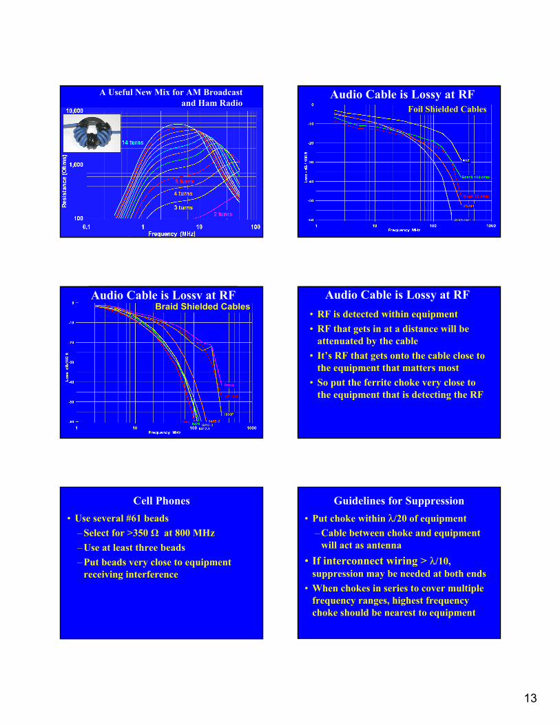
A Useful New Mix for AM Broadcast and Ham Radio
Audio Cable is Lossy at RFFoil Shielded Cables
Audio Cable is Lossy at RFBraid Shielded Cables
Audio Cable is Lossy at RF• RF is detected within equipment• RF that gets in at a distance will be
attenuated by the cable• It’s RF that gets onto the cable close to
the equipment that matters most• So put the ferrite choke very close to
the equipment that is detecting the RF
Cell Phones• Use several #61 beads
– Select for >350 Ω at 800 MHz– Use at least three beads– Put beads very close to equipment
receiving interference
Guidelines for Suppression• Put choke within λ/20 of equipment
– Cable between choke and equipment will act as antenna
• If interconnect wiring > λ/10, suppression may be needed at both ends
• When chokes in series to cover multiple frequency ranges, highest frequency choke should be nearest to equipment

14
Choosing a Ferrite Part• Below resonance, Z will be approximately
proportional to:– Length of part that surrounds the wire– ln (D/d) where D is the outer diameter
and d is the inner diameter– N2
– µ (varies with frequency)
Choosing a Ferrite Part• Thus, to maximize suppression use a part
that:– is longer– fits the wire most snugly– is thicker– is of a material has greater series R
Resonance and Suppression• Ferrite chokes for suppression generally:
– provide the greatest suppression at resonance
– are effective for <1 octave above resonance – are effective for 1-3 octaves below resonance
Ferrites and Loss
• Ferrites for suppression should be very “lossy” within the spectrum they need to suppress
• Ferrites for transformers and inductorsshould have as little loss as possible within the spectrum where they are operating
Other Ferrite Characteristics
• The resistivity varies over 5 orders of magnitude from one mix to another– Some are good insulators– Some are rather conductive
• Ferrites saturate at high signal levels, reducing µ
• µ decreases with increasing temperature
Measuring Ferrite Chokes• Antenna Analyzer ($500 - $2,000)
– AEA CIA-series• Lab Test Equipment ($10K - $30K)
– Network Analyzer – Impedance Bridge or Analyzer
• RF generator, series resistor, and voltmeter (or scope, or spectrum analyzer)
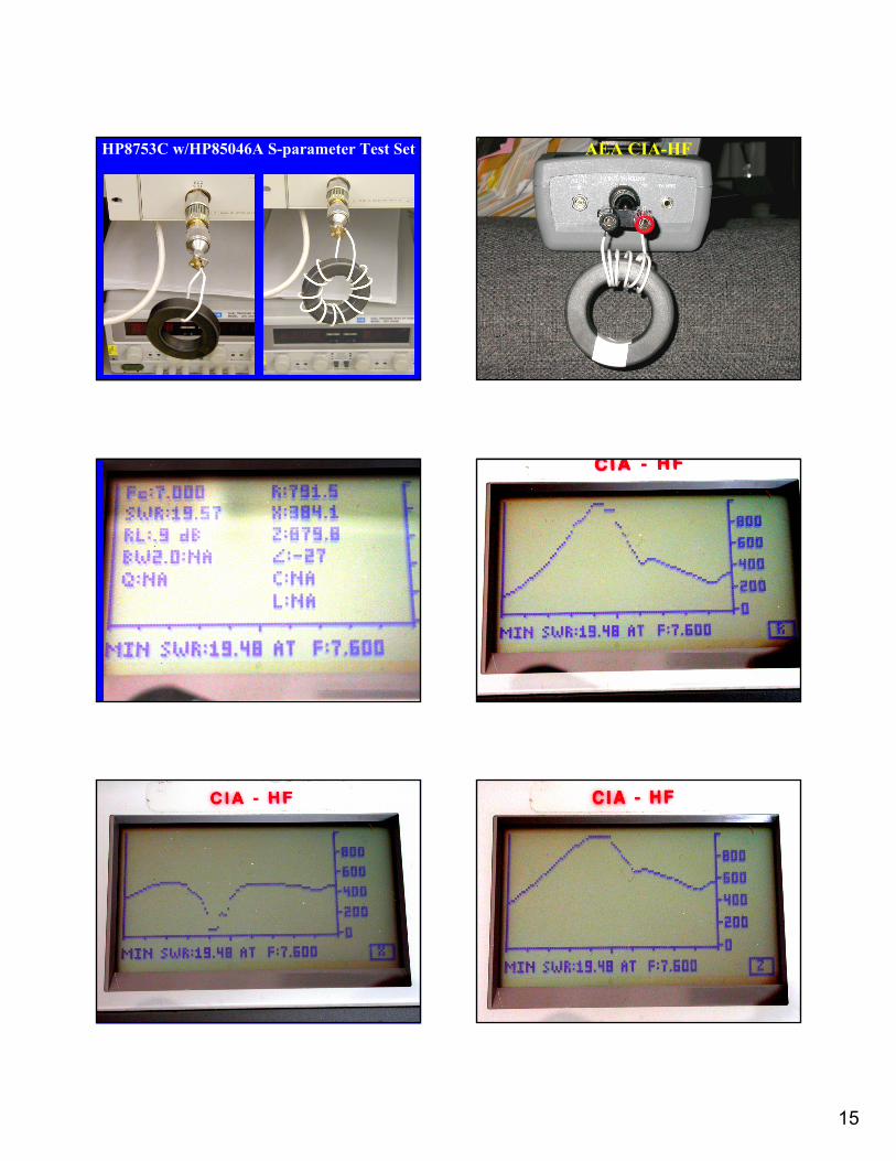
15
HP8753C w/HP85046A S-parameter Test Set AEA CIA-HF

16
Limitations of CIA and MFJ
• Input capacitance 15 pF detunes the choke– Moves resonance down (sometimes a lot!)
• Input resistance of 1.5K ohms limits accuracy at high impedance
• Accuracy degrades for ZX >> 50 ohms• Don’t trust Z at frequencies > 10 MHz
Measured With Lab-Quality Gear#61 Toroid
Measured With AEA CIA-HF
Stray capacitance Causes majorerrors in fR
Three Kinds of Ham RFI
• Interference from ham radio to other gear• Interference to ham radio • RF in the shack
Basic Interference Mechanisms• Pin 1 problems (both ways!)
– Fix them– Chokes can help
• Coupled on input and output wiring– Low pass filters– Chokes can help
• Radiated directly to/from circuitry– Shield equipment and ground the shield– Good interior design to minimize loops– Chokes cannot help
The Principle of Reciprocity
• If the mechanism is passive, what helps minimize received interference will generally also help reduce transmitted noise– Anything Digital– Anything with a microprocessor– Anything with a clock (or oscillator)– Computers– Appliances– Home Entertainment– Power supplies

17
What Needs to Be Choked for Ham RFI to Home Entertainment Systems?
• Anything that can act as an antenna!– RF coax lead-ins– Video cables– Audio cables– Power cables
RFI to Telephones
• Try ferrite chokes first– Telephone wiring– Power supply
• Common mode chokes– K-Com bifilar-wound choke, about 15 mH– A lot more choke than you can easily do yourself
– http://www.k-comfilters.com
RFI to Doorbells, DC Alarm Circuits
• Simple low-pass filters– Series choke, parallel capacitor– Series resistor, parallel capacitor– K-com filters
RFI to Ground Fault Interrupters (GFCI)
• Detects imbalance between hot (phase) and neutral, interrupts if > 5 mA
• There’s active electronics inside– Can false trigger on RF (mostly HF) – Add 0.1 µF 1 kV capacitor between
phase and conduit
Identifying RFI to the Ham Bands• Check your own house first!
– Kill power to your house and listen with battery power
• With power restored, listen with a talkie that covers HF
• RF noise from power lines is mostly arcing at insulators, almost never from transformers
• Use a directional antenna to listen at VHF, even when problem is at HF
• At HF, listen to the “grounding” downleads
Common RF Noise Sources at Home
• Anything Digital• Anything with a microprocessor• Anything with a clock (or oscillator)• Anything with a motor or switch
– Computers– Appliances– Home Entertainment– Power supplies– Radios
18
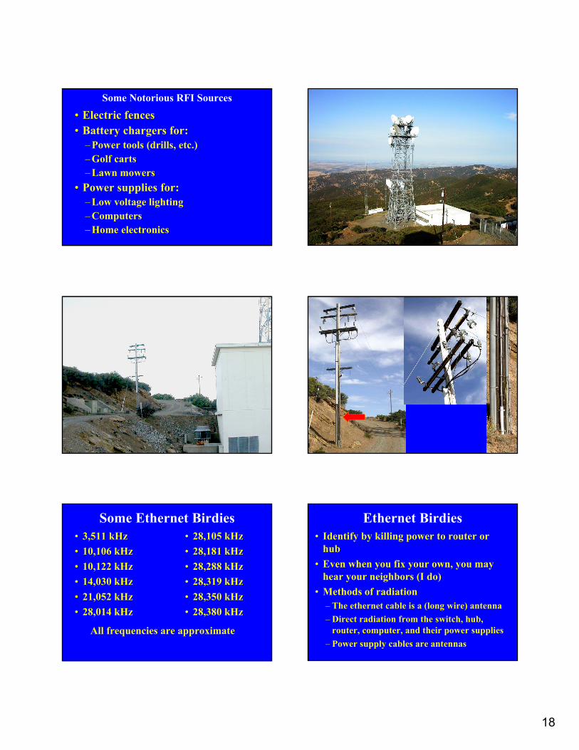
Some Notorious RFI Sources
• Electric fences• Battery chargers for:
– Power tools (drills, etc.)– Golf carts– Lawn mowers
• Power supplies for:– Low voltage lighting– Computers– Home electronics
Some Ethernet Birdies• 3,511 kHz• 10,106 kHz• 10,122 kHz• 14,030 kHz • 21,052 kHz• 28,014 kHz
• 28,105 kHz• 28,181 kHz• 28,288 kHz• 28,319 kHz• 28,350 kHz• 28,380 kHz
All frequencies are approximate
Ethernet Birdies• Identify by killing power to router or
hub• Even when you fix your own, you may
hear your neighbors (I do)• Methods of radiation
– The ethernet cable is a (long wire) antenna– Direct radiation from the switch, hub,
router, computer, and their power supplies– Power supply cables are antennas

19
Ethernet Birdies• Chokes will kill the common mode
radiation (long wire) from the cable• Use choke(s) on each cable (and each
end of long cables) (Each end talks)• Use multiple chokes if needed for wide
frequency ranges, putting highest frequency choke nearest to noise source
• Choke the power supply too!
A Look at Baluns
• A W2DU balun (called a “current” or “choke” balun) is simply a lot of beads strung onto the end of the coax
• All baluns are not created equal!• It is possible to overheat and short out a
W2DU balun with too much current – That resistance is real, and the power it
dissipates can “cook” the coax! – I’ve done it with 100 watts!
W2DU Balun (the REAL one) 50 - #73 beads
W2DU Balun (the REAL one) 50 - #73 beads
W2DU Balun (from QST) 50 - #73 beads
Two baluns measured
Palomar Balun Kit for RG8 Acknowledgements
• Bill Whitlock• Ron Steinberg (K9IKZ)• Leo Irakliotis (KC9GLI)• Neil Muncy (ex-W3WJE)• Steve Kusiceil• Fair-Rite Products

20
References• Fair-Rite Products Catalog This 200-page catalog is a wealth of
product data and applications guidance on practical ferrites. This company is a class act. http://www.fair-rite.com The vast majority of ferrite parts available at retail in the US are made by Fair-Rite.
• Ferroxcube Catalog and Applications Notes More online from another great manufacturer of ferrites. http://www.ferroxcube.com
• E. C. Snelling, Soft Ferrites, Properties and Applications, CRC Press, 1969 The bible on ferrites, but heavy math and physics.
• Henry Ott, Noise Reduction Techniques in Electronic Systems, Wiley Interscience, 1988 The best book there is on EMC.
• ARRL RFI Book• Marv Loftness, AC Power Interference Handbook (ARRL)• Applications notes on my website – http://audiosystemsgroup.com
Understanding and Eliminating RF Interference
Jim Brown (K9YC)Audio Systems Group, Inc.
http://audiosystemsgroup.com