Motorola 2007 UMTS LTE Air-Interface Technical Description -- with formulas and examples (very good)
Upload
remon-adel-asaadCategory
view
126download
1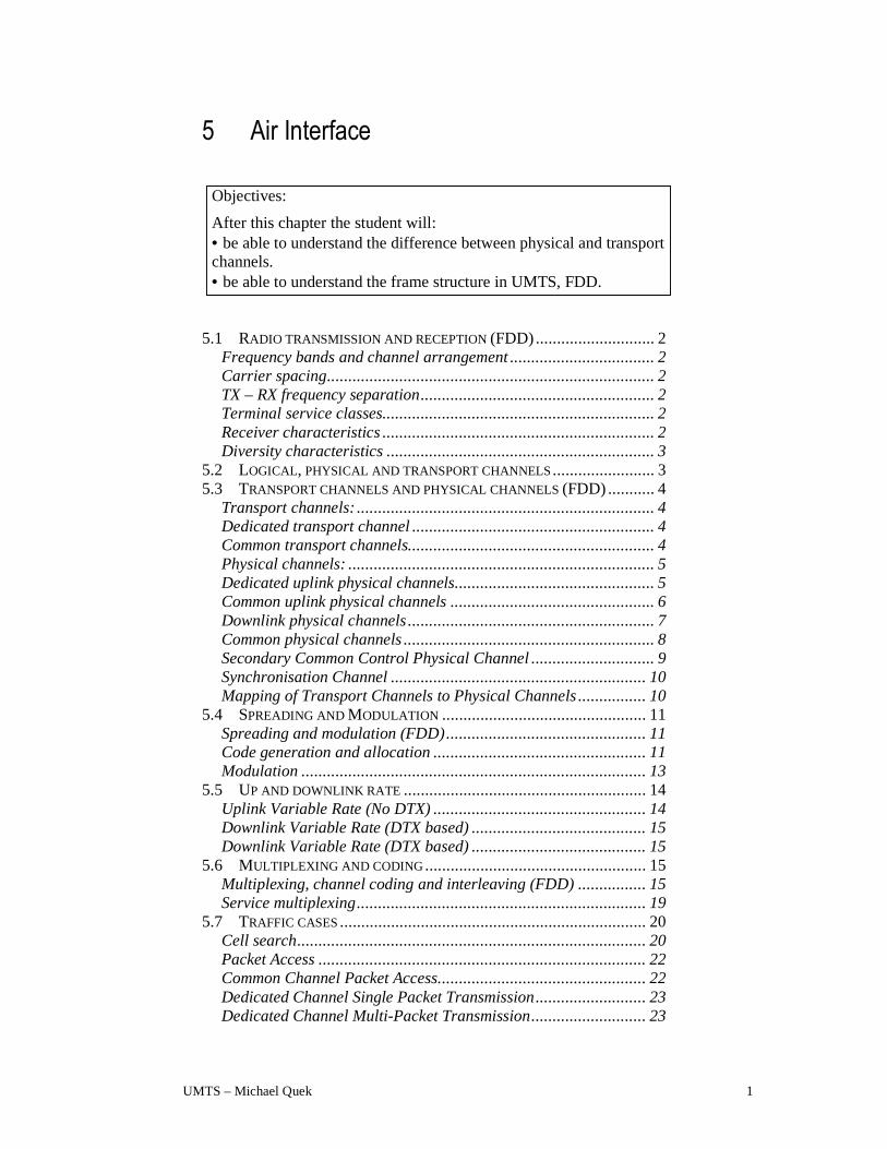
UMTS – Michael Quek 1
5 Air Interface
Objectives:
After this chapter the student will: • be able to understand the difference between physical and transport channels. • be able to understand the frame structure in UMTS, FDD.
5.1 RADIO TRANSMISSION AND RECEPTION (FDD)............................ 2
Frequency bands and channel arrangement .................................. 2 Carrier spacing............................................................................. 2 TX – RX frequency separation....................................................... 2 Terminal service classes................................................................ 2 Receiver characteristics ................................................................ 2 Diversity characteristics ............................................................... 3
5.2 LOGICAL, PHYSICAL AND TRANSPORT CHANNELS........................ 3 5.3 TRANSPORT CHANNELS AND PHYSICAL CHANNELS (FDD) ........... 4
Transport channels: ...................................................................... 4 Dedicated transport channel ......................................................... 4 Common transport channels.......................................................... 4 Physical channels: ........................................................................ 5 Dedicated uplink physical channels............................................... 5 Common uplink physical channels ................................................ 6 Downlink physical channels.......................................................... 7 Common physical channels ........................................................... 8 Secondary Common Control Physical Channel ............................. 9 Synchronisation Channel ............................................................ 10 Mapping of Transport Channels to Physical Channels ................ 10
5.4 SPREADING AND MODULATION ................................................ 11 Spreading and modulation (FDD)............................................... 11 Code generation and allocation .................................................. 11 Modulation ................................................................................. 13
5.5 UP AND DOWNLINK RATE ......................................................... 14 Uplink Variable Rate (No DTX) .................................................. 14 Downlink Variable Rate (DTX based) ......................................... 15 Downlink Variable Rate (DTX based) ......................................... 15
5.6 MULTIPLEXING AND CODING.................................................... 15 Multiplexing, channel coding and interleaving (FDD)................ 15 Service multiplexing.................................................................... 19
5.7 TRAFFIC CASES........................................................................ 20 Cell search.................................................................................. 20 Packet Access ............................................................................. 22 Common Channel Packet Access................................................. 22 Dedicated Channel Single Packet Transmission.......................... 23 Dedicated Channel Multi-Packet Transmission........................... 23

UMTS – Michael Quek 2
Radio transmission and reception (FDD)
Frequency bands and channel arrangement UTRA/FDD is designed to operate in the following paired band:
1920 – 1980 MHz Mobile station transmit Base station receive
2110 – 2170 MHz Mobile station receive Base station transmit
Proposed frequency band for UTRA/FDD
Carrier spacing The nominal channel spacing is 5 MHz, but this can be adjusted to optimise performance in particular deployment scenarios. The channel raster is 200 kHz, which means that the carrier frequency must be a multiple of 200 kHz.
TX – RX frequency separation The minimum transmit to receive separation is 130 MHz when operating in the paired band
Terminal service classes A number of different service classes will be used to define the data rate and code allocation for a UTRA/FDD terminal. Possible types of service class profiles are 144 kbps, 384 kbps and 2048 kbps.
Output power dynamics The transmitter uses fast closed-loop Carrier/Interference based power control and slow quality-based power control on both the uplink and downlink.
Uplink (UL) Downlink (DL)
Power control steps Variable 0.25-1.5 dB Variable 0.25-1.5 dB
Minimum transmit power -50 dBm [ ] dBm
Power control cycles per second 1.5 kHz 1.6 kHz
Power control dynamic 80 dB 30 dB
Output power dynamics for UL and DL
Receiver characteristics A Rake receiver or any other suitable receiver structure using coherent reception in both channel impulse response estimation, and code tracking procedures is assumed.
UMTS – Michael Quek 3
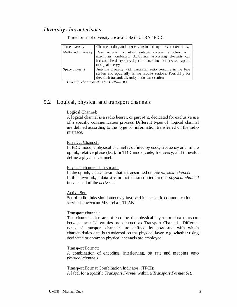
Diversity characteristics Three forms of diversity are available in UTRA / FDD:
Time diversity Channel coding and interleaving in both up link and down link.
Multi-path diversity Rake receiver or other suitable receiver structure with maximum combining. Additional processing elements can increase the delay-spread performance due to increased capture of signal energy.
Space diversity Antenna diversity with maximum ratio combing in the base station and optionally in the mobile stations. Possibility for downlink transmit diversity in the base station.
Diversity characteristics for UTRA/FDD
5.2 Logical, physical and transport channels
Logical Channel: A logical channel is a radio bearer, or part of it, dedicated for exclusive use of a specific communication process. Different types of logical channel are defined according to the type of information transferred on the radio interface.
Physical Channel: In FDD mode, a physical channel is defined by code, frequency and, in the uplink, relative phase (I/Q). In TDD mode, code, frequency, and time-slot define a physical channel.
Physical channel data stream: In the uplink, a data stream that is transmitted on one physical channel. In the downlink, a data stream that is transmitted on one physical channel in each cell of the active set.
Active Set: Set of radio links simultaneously involved in a specific communication service between an MS and a UTRAN.
Transport channel: The channels that are offered by the physical layer for data transport between peer L1 entities are denoted as Transport Channels. Different types of transport channels are defined by how and with which characteristics data is transferred on the physical layer, e.g. whether using dedicated or common physical channels are employed.
Transport Format: A combination of encoding, interleaving, bit rate and mapping onto physical channels. Transport Format Combination Indicator (TFCI): A label for a specific Transport Format within a Transport Format Set.
UMTS – Michael Quek 4
Transport Format Set: A set of Transport Formats. For example, a variable rate DCH has a Transport Format Set (one Transport Format for each rate), whereas a fixed rate DCH has a single Transport Format.
5.3 Transport channels and physical channels (FDD)
Transport channels:
Dedicated transport channel
DCH - Dedicated Channel The Dedicated Channel (DCH) is a downlink or uplink transport channel that is used to carry user or control information between the network and a mobile station. The DCH is transmitted over the entire cell or over only a part of the cell using lobe-forming antennas.
Common transport channels BCH - Broadcast Channel The Broadcast Channel (BCH) is a downlink transport channel that is used to broadcast system- and cell-specific information. The BCH is always transmitted over the entire cell. FACH - Forward Access Channel The Forward Access Channel (FACH) is a downlink transport channel that is used to carry control information to a mobile station when the system knows the location cell of the mobile station. The FACH may also carry short user packets. The FACH is transmitted over the entire cell or over only a part of the cell using lobe-forming antennas. PCH - Paging Channel The Paging Channel (PCH) is a downlink transport channel that is used to carry control information to a mobile station when the system does not know the location cell of the mobile station. The PCH is always transmitted over the entire cell. RACH - Random Access Channel The Random Access Channel (RACH) is an uplink transport channel that is used to carry control information from a mobile station. The RACH may also carry short user packets. The RACH is always received from the entire cell. DSCH – Downlink Shared Channel The downlink shared channel (DSCH) is a downlink transport channel shared by several UEs carrying dedicated control or traffic data.
UMTS – Michael Quek 5
Physical channels: A physical channel corresponds to a specific carrier frequency, code, and, on the uplink, relative phase (0 or π/2).
Dedicated uplink physical channels There are two types of uplink dedicated physical channels, the uplink Dedicated Physical Data Channel (uplink DPDCH) and the uplink Dedicated Physical Control Channel (uplink DPCCH).
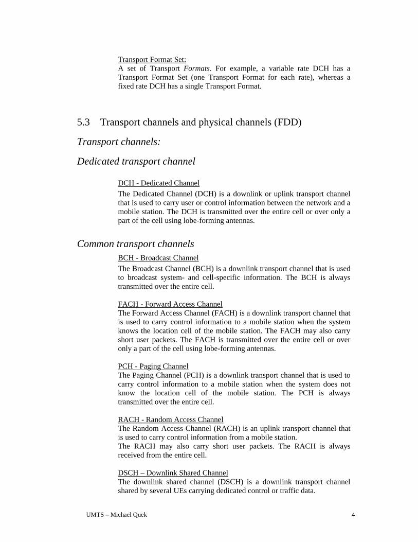
The uplink DPDCH is used to carry dedicated data generated for the dedicated transport channel (DCH). There may be zero, one, or several uplink DPDCHs on each connection. The uplink DPCCH is used to carry control information. The control information consists of known pilot bits to support channel estimation for coherent detection, transmit power-control (TPC) commands, and an optional transport-format indicator (TFI). The transport-format indicator informs the receiver about the instantaneous parameters of the different transport channels multiplexed on the uplink DPDCH. There is one and only one uplink DPCCH on each connection. Frame structure Each frame of length 10 ms is split into 16 slots, each of length Tslot = 0.625 ms, corresponding to one power-control period. A super frame corresponds to 72 consecutive frames, i.e. the super-frame length is 720ms.
Pilot TFCI
Data
Slot #1 Slot #2 Slot #i Slot #15
Frame #1 Frame #2 Frame # i Frame #72
0,666 ms, 10*2k bits (k=0..6)
Tf = 10 ms
Tsuper = 720 ms
DPDCH
DPCCHTPC
Frame structure for uplink DPDCH/DPCCH

UMTS – Michael Quek 6
The parameter k determines the number of bits per uplink DPDCH/DPCCH slot. It is related to the spreading factor SF of the physical channel as SF = 256/2k. The spreading factor may thus range from 256 down to 4. Note that an uplink DPDCH and uplink DPCCH on the same connection generally are of different rates, i.e. have different spreading factors and different values of k. The exact number of bits of the different uplink DPCCH is yet to be determined.
Common uplink physical channels Physical Random Access Channel The Physical Random Access Channel (PRACH) is used to carry the RACH. It is based on a Slotted ALOHA approach, i.e. a mobile station can start the transmission of the PRACH at a number of well-defined time-offsets, relative to the frame boundary of the received BCCH of the current cell. The different time offsets are denoted access slots and are spaced 1.5 ms. Information on what access slots are available in the current cell is broadcast on the BCCH.
1.5 ms
Random-access burstAccess slot #1
Random-access burstAccess slot #2
Random-access burstAccess slot #i
Random-access burstAccess slot #8
Offset of access slot #i
Frame boundary
Access slot.
The random access burst consists of two parts, a preamble part of length 1 ms and a message part of length 10 ms. Between the preamble part and the message part there is an idle time period of length 1.5 ms (preliminary value). The idle time period allows for detection of the preamble part and subsequent on-line processing of the message part. Preamble part The preamble part of the random-access burst consists of a signature. There are a total of 16 different signatures. Message part The message part of the random-access burst has the same structure as the uplink dedicated physical channel. It consists of a data part, corresponding to the uplink DPDCH, and a control part, corresponding to the uplink
UMTS – Michael Quek 7
DPCCH. The data and control parts are transmitted in parallel. The data part carries the random access request or small user packets. The spreading factor of the data part is limited to SF∈{256, 128, 64, 32} corresponding to channel bit rates of 16, 32, 64, and 128 kbps respectively. The control part carries pilot bits and rate information, using a spreading factor of 256. The rate information indicates which channelisation code (or rather the spreading factor of the channelisation code) is used on the data part.
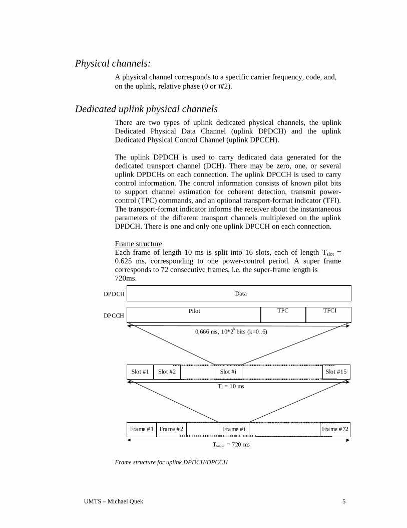
The random-access burst consists of the following fields (the values in brackets are preliminary values): • Mobile station identification. The MS ID is chosen at random by the
mobile station at the time of each random-access attempt. • Required Service. This field informs the base station what type of
service is required (short packet transmission, dedicated-channel set-up, etc.)
• An optional user packet • A CRC to detect errors in the data part of the random-access burst.
Structure of random-access burst data part
Downlink physical channels Dedicated physical channels There is only one type of downlink dedicated physical channel, the Downlink Dedicated Physical Channel (downlink DPCH).
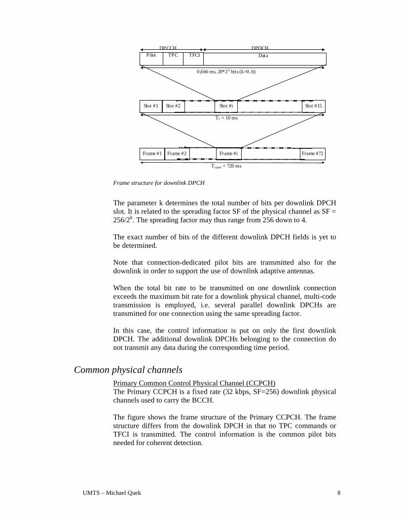
Within one downlink DPCH, dedicated data for the dedicated transport channel (DCH), is transmitted with control information (known pilot bits, TPC commands, and an optional TFCI). Frame structure The figure shows the frame structure of the downlink DPCH. Each frame of length 10 ms is split into 15 slots, each of length Tslot = 0.666 ms, corresponding to one power-control period. A super frame corresponds to 72 consecutive frames, i.e. the super-frame length is 720 ms.
MS ID Req. Ser. Optional user packet CRC
UMTS – Michael Quek 8
TPC
Slot #1 Slot #2 Slot #i Slot #15
Frame #1 Frame #2 Frame #i Frame #72
0,666 ms, 20*2k bits (k=0..6)
Pilot Data
DPCCH DPDCH
Tf = 10 ms
Tsuper = 720 ms
TFCI
Frame structure for downlink DPCH
The parameter k determines the total number of bits per downlink DPCH slot. It is related to the spreading factor SF of the physical channel as SF = 256/2k. The spreading factor may thus range from 256 down to 4. The exact number of bits of the different downlink DPCH fields is yet to be determined. Note that connection-dedicated pilot bits are transmitted also for the downlink in order to support the use of downlink adaptive antennas. When the total bit rate to be transmitted on one downlink connection exceeds the maximum bit rate for a downlink physical channel, multi-code transmission is employed, i.e. several parallel downlink DPCHs are transmitted for one connection using the same spreading factor. In this case, the control information is put on only the first downlink DPCH. The additional downlink DPCHs belonging to the connection do not transmit any data during the corresponding time period.
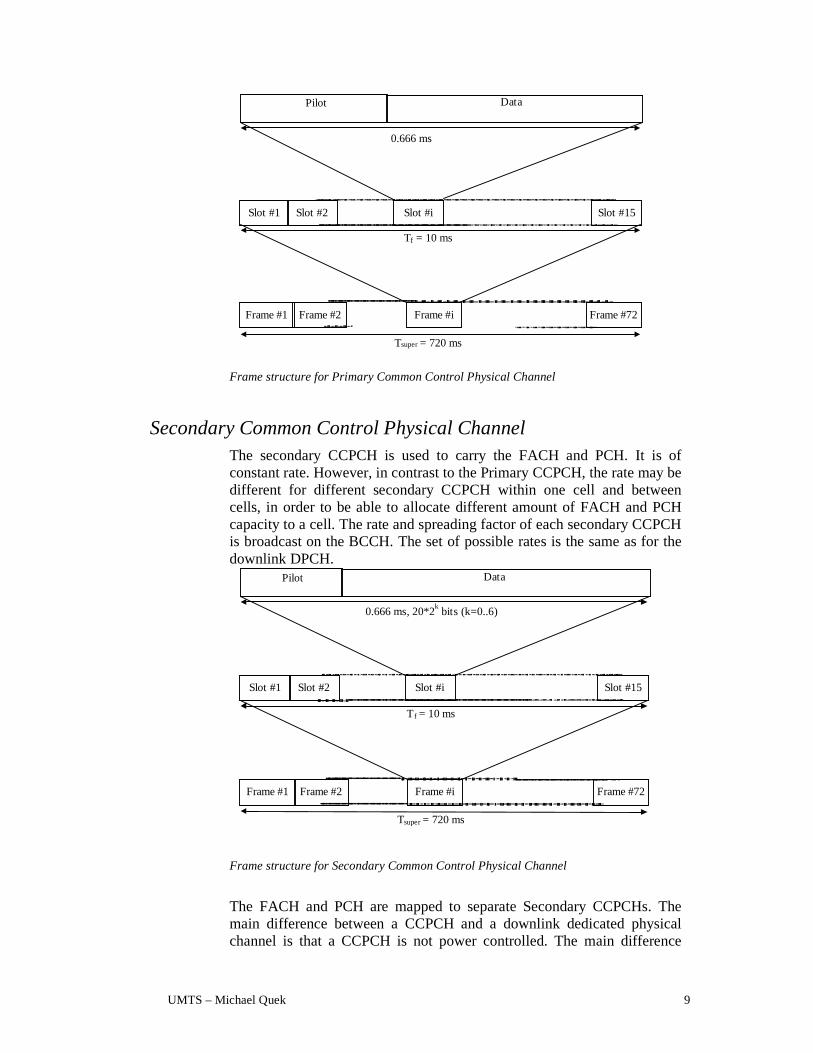
Common physical channels Primary Common Control Physical Channel (CCPCH) The Primary CCPCH is a fixed rate (32 kbps, SF=256) downlink physical channels used to carry the BCCH. The figure shows the frame structure of the Primary CCPCH. The frame structure differs from the downlink DPCH in that no TPC commands or TFCI is transmitted. The control information is the common pilot bits needed for coherent detection.
UMTS – Michael Quek 9
Data
Slot #1 Slot #2 Slot #i Slot #15
Frame #1 Frame #2 Frame #i Frame #72
0.666 ms
Pilot
Tf = 10 ms
Tsuper = 720 ms
Frame structure for Primary Common Control Physical Channel
Secondary Common Control Physical Channel The secondary CCPCH is used to carry the FACH and PCH. It is of constant rate. However, in contrast to the Primary CCPCH, the rate may be different for different secondary CCPCH within one cell and between cells, in order to be able to allocate different amount of FACH and PCH capacity to a cell. The rate and spreading factor of each secondary CCPCH is broadcast on the BCCH. The set of possible rates is the same as for the downlink DPCH.
Slot #1 Slot #2 Slot #i Slot #15
Frame #1 Frame #2 Frame #i Frame #72
0.666 ms, 20*2k bits (k=0..6)
Pilot Data
T f = 10 ms
Tsuper = 720 ms
Frame structure for Secondary Common Control Physical Channel
The FACH and PCH are mapped to separate Secondary CCPCHs. The main difference between a CCPCH and a downlink dedicated physical channel is that a CCPCH is not power controlled. The main difference

UMTS – Michael Quek 10
between the Primary and Secondary CCPCH is that the Primary CCPCH has a fixed predefined rate while the Secondary CCPCH has a constant rate that may be different for different cells, depending on the capacity needed for FACH and PCH. Furthermore, a Primary CCPCH is continuously transmitted over the entire cell while a Secondary CCPCH is only transmitted when there is data available and may be transmitted in a narrow lobe in the same way as a dedicated physical channel (only valid for a Secondary CCPCH carrying the FACH).
Synchronisation Channel The Synchronisation Channel (SCH) is a downlink signal used for cell search. The SCH consists of two sub channels, the Primary and Secondary SCH.
cp : Primary Synchronization Codecs
i,k: One of 17 possible Secondary Synchronization Codes
cp
csi,1
cp cp
Tslot = 2560 chipschips
Tframe = 16*Tslot
Primary SCH
Secondary SCH
256 chips
csi,2 cs
i,16
(csi,1, cs
i,2, ..., csi,16) encode cell specific long scrambling code group i
Structure of Synchronisation Channel (SCH)
The Primary SCH consists of an unmodulated orthogonal code of length 256 chips, the Primary Synchronisation Code, transmitted once every slot. The Primary Synchronisation Code is the same for every base station in the system. The Secondary SCH consists of repeatedly transmitting a length 16 sequence of unmodulated orthogonal codes of length 256 chips, the Secondary Synchronisation Codes, transmitted in parallel with the Primary Synchronisation channel. The sequence on the Secondary SCH indicates which of the 32 different code groups the base station downlink scrambling code belongs. 32 sequences are used to encode the 32 different code groups each containing 16 scrambling codes. It is used to uniquely determine both the long code group and the frame timing.
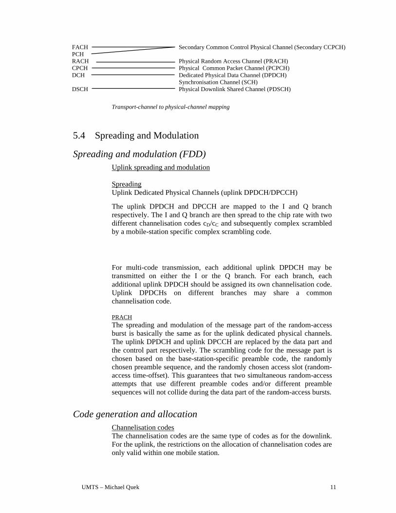
Mapping of Transport Channels to Physical Channels The figure summarises the mapping of transport channels to physical channels.
Transport Channels Physical Channels BCCH Primary Common Control Physical Channel (Primary CCPCH)
UMTS – Michael Quek 11
FACH Secondary Common Control Physical Channel (Secondary CCPCH) PCH RACH Physical Random Access Channel (PRACH) CPCH Physical Common Packet Channel (PCPCH) DCH Dedicated Physical Data Channel (DPDCH) Synchronisation Channel (SCH) DSCH Physical Downlink Shared Channel (PDSCH)
Transport-channel to physical-channel mapping
5.4 Spreading and Modulation
Spreading and modulation (FDD) Uplink spreading and modulation Spreading Uplink Dedicated Physical Channels (uplink DPDCH/DPCCH)
The uplink DPDCH and DPCCH are mapped to the I and Q branch respectively. The I and Q branch are then spread to the chip rate with two different channelisation codes cD/cC and subsequently complex scrambled by a mobile-station specific complex scrambling code.
For multi-code transmission, each additional uplink DPDCH may be transmitted on either the I or the Q branch. For each branch, each additional uplink DPDCH should be assigned its own channelisation code. Uplink DPDCHs on different branches may share a common channelisation code.
PRACH The spreading and modulation of the message part of the random-access burst is basically the same as for the uplink dedicated physical channels. The uplink DPDCH and uplink DPCCH are replaced by the data part and the control part respectively. The scrambling code for the message part is chosen based on the base-station-specific preamble code, the randomly chosen preamble sequence, and the randomly chosen access slot (random-access time-offset). This guarantees that two simultaneous random-access attempts that use different preamble codes and/or different preamble sequences will not collide during the data part of the random-access bursts.
Code generation and allocation Channelisation codes The channelisation codes are the same type of codes as for the downlink. For the uplink, the restrictions on the allocation of channelisation codes are only valid within one mobile station.
UMTS – Michael Quek 12
Each connection is allocated at least one uplink channelisation code, to be used for the uplink DPCCH. In most cases, at least one additional uplink channelisation code is allocated for a uplink DPDCH. Further uplink channelisation codes may be allocated if more than one uplink DPDCH are required. As different mobile stations use different uplink scrambling codes, the uplink channelisation codes may be allocated with no co-ordination between different connections. The uplink channelisation codes are therefore always allocated in a pre-defined order. The mobile-station and network only need to agree on the number and length (spreading factor) of the uplink channelisation codes. The exact codes to be used are then implicitly given.
Scrambling codes Either short or long scrambling codes should be used on uplink. Short scrambling code The short scrambling code is a complex code c’scramb = cI+jcQ, where cI and cQ are two different codes of length 256. The network decides the uplink short scrambling code. The mobile station is informed about what short scrambling code to use in the downlink Access Grant message that is the base-station response to an uplink Random Access Request. The short scrambling code may, in rare cases, be changed during the duration of a connection. Long scrambling code The long uplink scrambling code is typically used in cells without multi-user detection in the base station. The mobile station is informed if a long scrambling code should be used in the Access Grant Message following a random-access request and in the handover message. Random access codes
Preamble spreading code The spreading code for the preamble part is cell specific and is broadcast by the base station. More than one preamble code can be used in a base station if the traffic load is high. The preamble codes must be code planned, since two neighbouring cells should not use the same preamble code. The code used is a 256 chip code. All 256 codes are used in the system. Preamble signature The preamble part carries one of 16 different signatures of length 16, <P0, P1, ..., P15>. The base station broadcasts which signatures are allowed to be used in a cell. Channelisation codes for the message part
UMTS – Michael Quek 13
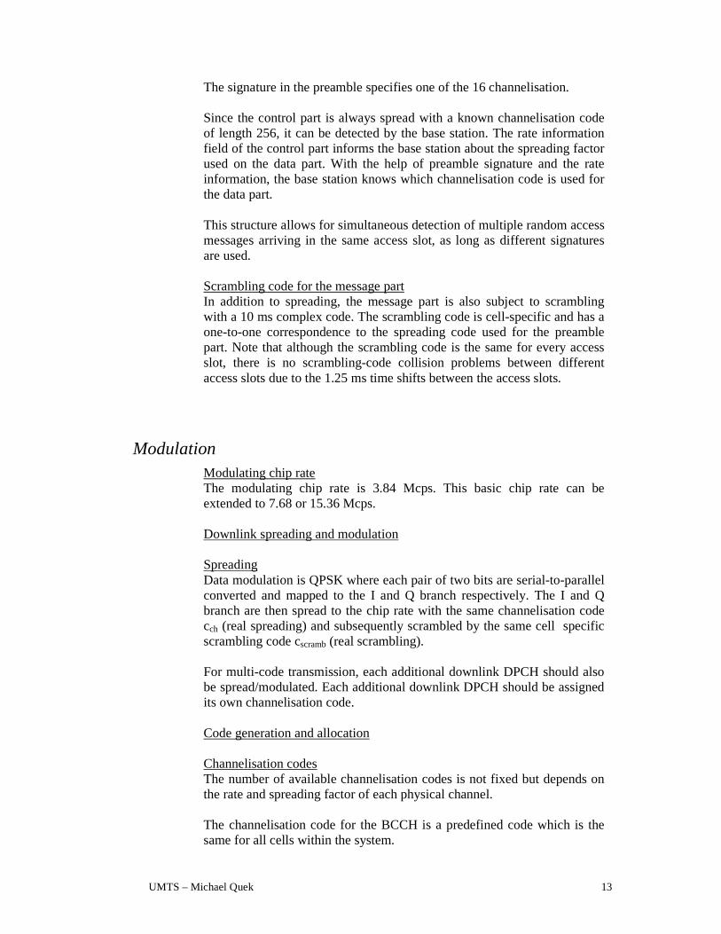
The signature in the preamble specifies one of the 16 channelisation.
Since the control part is always spread with a known channelisation code of length 256, it can be detected by the base station. The rate information field of the control part informs the base station about the spreading factor used on the data part. With the help of preamble signature and the rate information, the base station knows which channelisation code is used for the data part. This structure allows for simultaneous detection of multiple random access messages arriving in the same access slot, as long as different signatures are used. Scrambling code for the message part In addition to spreading, the message part is also subject to scrambling with a 10 ms complex code. The scrambling code is cell-specific and has a one-to-one correspondence to the spreading code used for the preamble part. Note that although the scrambling code is the same for every access slot, there is no scrambling-code collision problems between different access slots due to the 1.25 ms time shifts between the access slots.
Modulation Modulating chip rate The modulating chip rate is 3.84 Mcps. This basic chip rate can be extended to 7.68 or 15.36 Mcps.
Downlink spreading and modulation Spreading Data modulation is QPSK where each pair of two bits are serial-to-parallel converted and mapped to the I and Q branch respectively. The I and Q branch are then spread to the chip rate with the same channelisation code cch (real spreading) and subsequently scrambled by the same cell specific scrambling code cscramb (real scrambling).
For multi-code transmission, each additional downlink DPCH should also be spread/modulated. Each additional downlink DPCH should be assigned its own channelisation code.
Code generation and allocation
Channelisation codes The number of available channelisation codes is not fixed but depends on the rate and spreading factor of each physical channel. The channelisation code for the BCCH is a predefined code which is the same for all cells within the system.

UMTS – Michael Quek 14
The channelisation code(s) used for the Secondary Common Control Physical Channel is broadcast on the BCCH. The channelisation codes for the downlink dedicated physical channels are decided by the network. The mobile station is informed about what downlink channelisation codes to receive in the downlink Access Grant message that is the base-station response to an uplink Random Access request. The set of channelisation codes may be changed during the duration of a connection, typically as a result of a change of service or an inter-cell handover. A change of downlink channelisation codes is negotiated over a DCH.
Scrambling code The total number of available scrambling codes is 512, divided into 32 code groups with 16 codes in each group. The grouping of the downlink codes is done in order to facilitate a fast cell search. The downlink scrambling code is assigned to the cell (sector) at the initial deployment. The mobile station learns about the downlink scrambling code during the cell search process. The scrambling codes are repeated for every 10 ms radio frame. Synchronisation codes The Primary and Secondary code words, Cp and {C1,…,C17} respectively, consist of pair wise mutually orthogonal codes of length 256.
5.5 Up and downlink rate
Uplink Variable Rate (No DTX)
10 ms
: DPCCH (Pilot+TPC+RI)
: DPDCH (Data)
Variable
rate
R = 1/2
1-rate
1/2-rate
1/4-rate
0-rate
R = 1
R = 0 R = 0
R = 1/2

UMTS – Michael Quek 15
Downlink Variable Rate (DTX based)
Downlink Variable Rate (DTX based)
5.6 Multiplexing and coding
Multiplexing, channel coding and interleaving (FDD) Transport-channel coding/multiplexing
0.666 ms
:DPCCH-part (Pilot+TPC+RI) :DPDCH-part (Data)
1-rate
1/2-rate
1/4-rate
0-rate
:DPCCH-part (Pilot+TPC+RI) :DPDCH-part (Data)
1-rate
1/2-rate
0-rate
Variable rate
10 ms
R = 1
R = 1/2
R = 1
R = 0
UMTS – Michael Quek 16
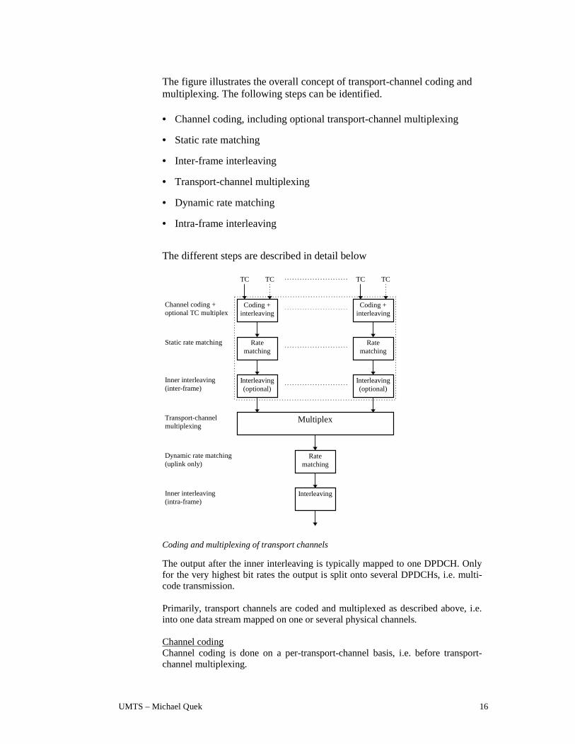
The figure illustrates the overall concept of transport-channel coding and multiplexing. The following steps can be identified.
• Channel coding, including optional transport-channel multiplexing
• Static rate matching
• Inter-frame interleaving
• Transport-channel multiplexing
• Dynamic rate matching
• Intra-frame interleaving
The different steps are described in detail below
Transport-channelmultiplexing
Channel coding +optional TC multiplex
Static rate matching
Inner interleaving(inter-frame)
Dynamic rate matching(uplink only)
Inner interleaving(intra-frame)
Coding +interleaving
Ratematching
Interleaving(optional)
Multiplex
TC
Coding +interleaving
Ratematching
Interleaving(optional)
Ratematching
Interleaving
TC TCTC
Coding and multiplexing of transport channels
The output after the inner interleaving is typically mapped to one DPDCH. Only for the very highest bit rates the output is split onto several DPDCHs, i.e. multi-code transmission. Primarily, transport channels are coded and multiplexed as described above, i.e. into one data stream mapped on one or several physical channels.
Channel coding Channel coding is done on a per-transport-channel basis, i.e. before transport-channel multiplexing.

UMTS – Michael Quek 17
Convolutionalcoding
Convolutionacoding
Outerinterleaving
Reed-Solomoncoding
Turbocoding
Service-specificcoding
Channel coding in UTRA/FDD
Convolutional coding Convolutional coding is typically applied for services that require a BER in the order of 10-3. Convolutional coding is also, in concatenation with RS coding + outer interleaving, applied to services that require a BER in the order of 10-6.
Typically, rate-1/3 convolutional coding is applied to dedicated transport channels (DCHs) in normal (non-slotted) mode while rate ½ convolutional coding is applied to DCHs in slotted mode.
Outer Reed-Solomon coding and outer interleaving Reed-Solomon coding + outer interleaving, is, in concatenation with inner convolutional coding, typically applied to transport channels that require a BER in the order of 10-6. The RS-coding is of approximate rate 4/5.
Turbo coding The use of Turbo coding for high data rate (above 32 kbps), high quality services, is currently being investigated within ETSI. Turbo codes of rate 1/3 and ½ (for the highest data rates), have been proposed to replace the concatenation of convolutional and Reed-Solomon codes. ETSI is awaiting further results of simulations illustrating the performance of Turbo Codes.
ConstituentEncoder #1
ParityBits
ParityBitsConstituent
Encoder #2Interleaver
Infobits
Puncture
Block diagram of a Turbo code encoder

UMTS – Michael Quek 18
If Turbo codes are shown to give an improved FEC for high quality services, compared with the existing proposal, then the basic FEC coding for the UTRA/FDD will be as shown in.
Convolutionalcoding
Channel interleaving
BER = 10 -3
Turbo coding
Channel interleaving
BER = 10 -6
Service-specific coding
FEC coding for UTRA/FDD when turbo codes are used
Service specific coding The service-specific-coding option allows for additional flexibility of the UTRA Layer 1 by allowing for additional coding schemes, in addition to the standard coding schemes listed above. One example is the use of unequal-error-protection coding schemes for certain speech-codecs.
Inner inter-frame interleaving Inner inter-frame bit interleaving is carried out on a per-transport-channel basis on those transport-channels that can allow for and require interleaving over more than one radio frame (10 ms). The span of the inner inter-frame interleaving can vary in the range 20 ms to 150 ms.
Rate matching Two types of rate matching is carried out:
• Static rate matching carried out on a slow basis, typically every time a
transport channel is added or removed from the connection.
• Dynamic rate matching carried out on a frame-by-frame (10 ms) basis
Static rate matching Static rate matching is used for two different reasons: • to adjust the coded transport channel bit rate to a level where minimum
transmission quality requirements of each transport channel is fulfilled with the smallest differences in channel bit energy
• to adjust the coded transport channel bit rate so that the maximum total bit rate after transport channel multiplexing is matched to the channel bit rate of the uplink and downlink dedicated physical channel
The static rate matching is based on code puncturing and unequal repetition.

UMTS – Michael Quek 19
Note that, although static rate matching is carried out prior to transport-channel multiplexing, the rate matching must be co-ordinated between the different transport channels. Dynamic rate matching Dynamic rate matching is carried out after the multiplexing of the parallel coded transport channels and is used to match the total instantaneous rate of the multiplexed transport channels to the channel bit rate of the uplink DPDCH. Dynamic rate matching uses unequal repetition and is only applied to the uplink. On the downlink, discontinuous transmission (DTX) is used when the total instantaneous rate of the multiplexed transport channels does not match the channel bit rate.
Transport-channel multiplexing The coded transport channels are serially multiplexed within one radio frame. The output after the multiplexer (before the inner interleaving) will thus be according to
TC-1 TC-2 TC-M
10 ms (one radio frame)
Transport channel multiplexing
As an option, transport channels may be multiplexed within the channel-coding unit, typically after outer RS coding but before outer interleaving.
Inner intra-frame interleaving Inner intra-frame interleaving over one radio frame (10 ms) is applied to the multiplexed set of transport channels.
Service multiplexing In a same connection, multiple services could be treated with separate channel coding/interleaving and mapping to different basic physical channels (slot/code). In this way QoS can be separately and independently controlled.
Coding/interleaving
Service 1
Service 2
Service N
Coding/interleaving
Coding/interleaving
Parallelservices
Service multiplexing (a)
UMTS – Michael Quek 20
A second alternative is time multiplexing at different points of the channel coding scheme.
Outercoding/interl.
Innercoding/interl.
TimeMux
TimeMux
TimeMuxParallel
servicesOuter
coding/interl.Inner
coding/interl.
TimeMux
TimeMux
Service 1Service 2Service n
Service multiplexing (b)
After service multiplexing and channel coding, the multi-service data stream is mapped to one or, if the total rate exceeds the upper limit for single-code transmission, several resource units.
5.7 Traffic cases
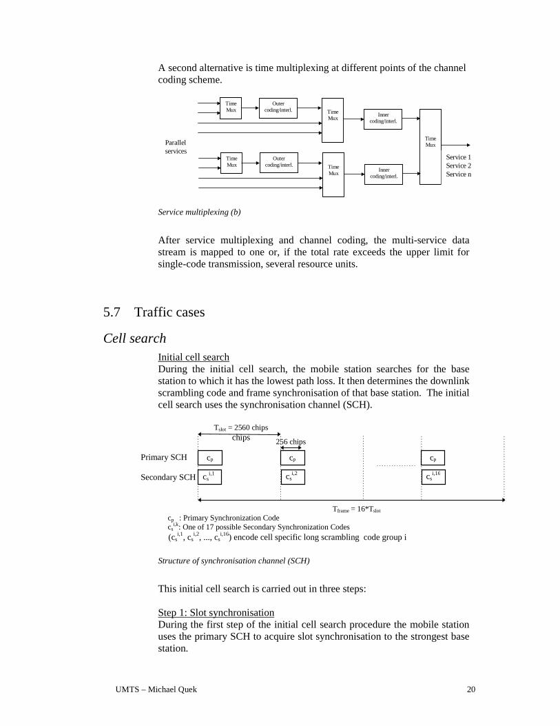
Cell search Initial cell search During the initial cell search, the mobile station searches for the base station to which it has the lowest path loss. It then determines the downlink scrambling code and frame synchronisation of that base station. The initial cell search uses the synchronisation channel (SCH).
cp : Primary Synchronization Codecs
i,k: One of 17 possible Secondary Synchronization Codes
cp
csi,1
cp cp
Tslot = 2560 chipschips
Tframe = 16*Tslot
Primary SCH
Secondary SCH
256 chips
csi,2 cs
i,16
(csi,1, cs
i,2, ..., csi,16) encode cell specific long scrambling code group i
Structure of synchronisation channel (SCH)
This initial cell search is carried out in three steps: Step 1: Slot synchronisation During the first step of the initial cell search procedure the mobile station uses the primary SCH to acquire slot synchronisation to the strongest base station.

UMTS – Michael Quek 21
This is done with a single matched filter (or any similar device) matched to the primary synchronisation code cp which is common to all base stations. The output of the matched filter will have peaks for each ray of each base station within range of the mobile station. Detecting the position of the strongest peak gives the timing of the strongest base station modulo the slot length. For better reliability, the matched-filter output should be non-coherently accumulated over a number of slots.
Matchedfilter (cp)
Slot-wiseaccumulation
Two rays from BSi One ray from BSj
Findmaximum
Timing modulo Tslot
Tslot
Matched-filter search for primary synchronisation code to slot synchronisation (timing modulo the slot length).
Step 2: Frame synchronisation and code-group identification During the second step of the initial cell search procedure, the mobile station uses the secondary SCH to find frame synchronisation and identify the code group of the base station found in the first step. This is done by correlating the received signal at the positions of the Secondary Synchronisation Code with all possible (16) Secondary Synchronisation Codes. Note that the position of the Secondary Synchronisation Code is known after the first step. The outputs of all the 17 correlators for 16 consecutive secondary SCH locations are used to form the decision variables. The decision variables are obtained by non-coherently summing the correlator outputs corresponding to each 16 length sequence out of the 32 possible sequences and its 16 cyclic shifts giving a total of 512 decision variables. Note that the cyclic shifts of the sequences are unique. Thus, by identifying the sequence/shift pair that gives the maximum correlation value, the code group as well as the frame synchronisation is determined.
Step 3: Scrambling-code identification During the third and last step of the initial cell-search procedure, the mobile station determines the exact scrambling code used by the found base station. The scrambling code is identified through symbol-by-symbol correlation over the Primary CCPCH with all scrambling codes within the code group identified in the second step. Note that, from step 2, the frame boundary and consequently the start of the scrambling code is known. Correlation must be carried out symbol-wise, due to the unknown data of the primary CCPCH. Also, in order to reduce the probability of wrong/false acquisition, due to combat background noise/interference, averaging the correlator outputs over a sequence of symbols (diversity) might be required before using the outputs to determine the exact scrambling code.

UMTS – Michael Quek 22
After the scrambling code has been identified, the Primary CCPCH can be detected, super-frame synchronisation can be acquired and the system- and cell specific BCCH information can be read.
Idle mode cell search When in idle mode, the mobile station continuously searches for new base stations on the current and other carrier frequencies. The cell search is done in basically the same way as the initial cell search. The main difference compared to the initial cell search is that an idle mobile station has received a priority list from the network. This priority list describes in which order the downlink scrambling codes should be searched for and does thus significantly reduce the time and effort needed for the scrambling-code search (step 3). Also the complexity in the second step may be reduced if the priority list only includes scrambling codes belonging to a subset of the total set of code groups. The priority list is continuously updated to reflect the changing neighbourhood of a moving mobile station.
Active mode cell search When in active mode, the mobile station continuously searches for new base stations on the current carrier frequency. This cell search is carried out in basically the same way as the idle mode cell search. The mobile station may also search for new base stations on other carrier frequencies using the slotted mode.
Packet Access The requirements for packet access is fast access and an efficient use of the radio resources. This would mean that the connection set-up should be fast and closed loop power control for large packets and a small overhead for small packets. The packets should also be able to be scheduled. Small frequently sent packets sent on the common channels. While frequently or large packets should use the dedicated channels.
Common Channel Packet Access
User
packet
User
packet
Access
request
Access
request
Arbitrary time
Common Channel (RACH/FACH)
Common Channel Packet Access
For small packets and medium data rates the common channel RACH/FACH would be used. During the time there are no packets to transmit there will be no link maintenance. Open loop power control.
UMTS – Michael Quek 23
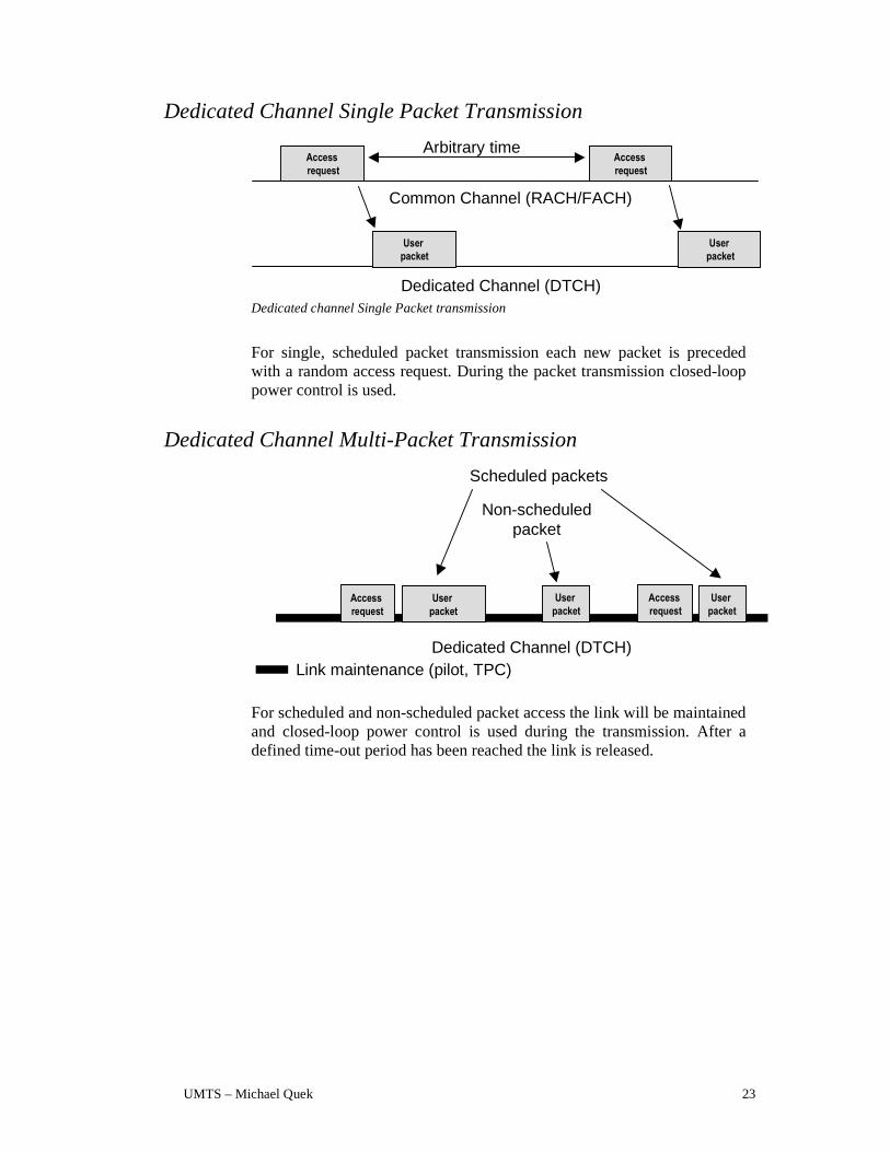
Dedicated Channel Single Packet Transmission
Access
request
Access
request
User
packet
User
packet
Arbitrary time
Common Channel (RACH/FACH)
Dedicated Channel (DTCH) Dedicated channel Single Packet transmission
For single, scheduled packet transmission each new packet is preceded with a random access request. During the packet transmission closed-loop power control is used.
Dedicated Channel Multi-Packet Transmission
Access
request
User
packet
User
packet
Access
request
User
packet
Dedicated Channel (DTCH)Link maintenance (pilot, TPC)
Scheduled packets
Non-scheduledpacket
For scheduled and non-scheduled packet access the link will be maintained and closed-loop power control is used during the transmission. After a defined time-out period has been reached the link is released.