Ultronics ZTS16 Twin Spool Valve Sense CAN Bus - Eatonpub/@eaton/@hyd/documents/content/... ·...
19
Ultronics ™ ZTS16 Twin Spool Valve 130 LPM 350 Bar Electronic Load Sense CAN Bus
Transcript of Ultronics ZTS16 Twin Spool Valve Sense CAN Bus - Eatonpub/@eaton/@hyd/documents/content/... ·...

Ultronics™ ZTS16 Twin Spool Valve
130 LPM 350 Bar
Electronic Load Sense CAN Bus

2 EATON Ultronics ZTS16 Technical Catalog E-VLMB-MC001-E3 January 2010
Table of Contents
General Information .................................................................................................................................................................3
Specifications ............................................................................................................................................................................4
Model Code ...............................................................................................................................................................................6
Principles of Operation ............................................................................................................................................................8
Performance Data .....................................................................................................................................................................9
Inlet Options ............................................................................................................................................................................10
Flow Share Methods ..............................................................................................................................................................11
Electrical ..................................................................................................................................................................................12
System Layout ........................................................................................................................................................................13
Work Port Valves ....................................................................................................................................................................14
Manual Override .....................................................................................................................................................................15
Interbank Connection Cables .................................................................................................................................................16
Installation Drawings .............................................................................................................................................................17

3EATON Ultronics ZTS16 Technical Catalog E-VLMB-MC001-E3 January 2010
General Information
Product Overview
Features and Benefits
The new Ultronics ZTS16 (referred to herein as Ultronics) electronic load sense control valve delivers high perfor-mance and reliable valve control during high demand, multi-functioning operational environments. This is possible via:
• Patented twin spool design
• Integrated pressure and position sensors
• On-board electronics & data processing
• Open architecture
• 130 LPM (35 gpm) flow rating
• 350 bar max pressure rating
• CANbus interface (J1939 or CANopen)
With its open architecture and CAN interface, Ultronics has the ability to be a complete Eaton control system* or simply a stand-alone valve solution in a nearly-infinite array of appli-cations for customers and end-users.
*Systems offerings may include
• Eaton EFX controllers
• Eaton ControlF(x)® software
• Ultronics Joysticks
Configurable Performance
Configurable valve para-meters allow for rapid and broad changes in valve per-formance, which reduces system development time, improves productivity with-out hardware changes.
Precise Control
A patented independent twin spool design allows precise control of meter-in and meter-out flow under varying load conditions. This reduces inefficiencies and performance compromises with traditional single spool designs.
Real-Time Diagnostics and Monitoring
Integrated sensors and configuration software enables real-time diag-nostics and performance monitoring. Thus, system developers can quickly and efficiently trouble-shoot and commission new systems.
Unique Applications Functionality
Ultronics’ open architecture allows users to develop their own application level pro-grams using Eaton’s Control F(x)® software and EFX controllers, or by using their own controller and associat-ed software. This facilitates advanced system functional-ity and flexibility.

4 EATON Ultronics ZTS16 Technical Catalog E-VLMB-MC001-E3 January 2010
Specifications
Pressure
Inlet (max)* 350 bar (5100 psi)Work port (max)* 350 bar (5100 psi)Tank** Min. 2 bar (30 psi), Max. 30 bar (435 psi)
Flow
Inlet (max) 200 lpm (53 gpm)Work port (max) 130 lpm (34 gpm)
Temperature
Ambient (operating) -40°C to 105°COil (operating) -20°C to 85°CStorage -40°C to 120°C
Filtration
ISO 4406 18/16/13
Electrical
Input Voltage 9 – 32 VDCCAN Interface J1939 2.0B CAN Open
Electromagnetic
Conducted Emissions CISPR 25: 2002Radiated Emissions CISPR 25: 2002Transient Emissions ISO 7637-2: 2004Radiated Immunity ISO 11452, CISPR 25: 2002, 2004/104/ECElectrostatic Discharge ISO 10605 and SAE J1113-13Power Frequency Magnet Field Immunity EN 61000-4-8Reverse Supply Protection -36VTransients Immunity ISO 7637-2:2004
Environmental
Ingress Protection IP67
*Note: Valve tested at 350 bar for 1 million cycles per NFPA T 2.6.1. Rated pressure per T 2.6.1. is 300 bar (4350 psi).**Note: With manual override, tank is limited to 10 bar (145 psi) maximum.

5EATON Ultronics ZTS16 Technical Catalog E-VLMB-MC001-E3 January 2010
Specifications
Viscosity
Recommended Viscosity 85 to 10 cSt 85 to 10 mm2/s Absolute Maximum Viscosity 2250 cSt 2250 mm2/sAbsolute Minimum Viscosity 7 cSt 7 mm2/s
Leakage
Max Leakage* 23 cc @ 100 Bar @ 23 cst * Data taken from work port to tank

6 EATON Ultronics ZTS16 Technical Catalog E-VLMB-MC001-E3 January 2010
1 Valve Series
ZTS – Ultronics ZTS16
2 Spool
16 – Size
3 Communication Interface
J – J1939 CAN 2.0B
O – CAN-Open
4 Interface Module
M – VSM - Valve System Module. One required per system located on first valve bank in sys-tem
E – VSE - Valve System Extender. Required when valve bank is greater than 4 meters from previous valve bank in system
0 – None - When valve is less than 4 meters from a VSM or VSE valve bank and daisy chain is desired
Note: if “0” is chosen, an interconnection cable must be ordered separately. See note below for part numbers.
Note: Maximum of 2 VSE allowed per system.
5 CAN Bus Terminator
T – One Section
0 – No CAN bus terminator - true when valve bank is the start of, or within, a daisy chain
6 Number of Sections in Valve Bank
1 – One Section
2 – Two Sections
3 – Three Sections
4 – Four Sections
5 – Five Sections
6 – Six Sections
7 Bank Type
C – Standard valve bank
8 Main Ports
S – Supply Ports: 1-1/16”-12UN (SAE-12), Tank Port: 1-5/16”-12UN (SAE-16), LS Port: 7/16”-18UNF (SAE-4)
B – Supply Ports: G3/4”, Tank Port: G1”, LS Port G1/4”
Note: LS port will not be included when fixed dis-placement inlet controller is selected.
9 Active Pressure Ports
1 – P1
2 – P2
3 – P3
4 – P1 & P2
5 – P1 & P3
6 – P2 & P3
7 – P1, P2 & P3
Note: Selections with P1 port are preferred as pri-mary pressure port but other options may be used depending on system layout.
Note: All active ports will be capped with plastic shipping plugs.
10 Inlet Pressure Controller
FDP – Used with fixed displacement pump
LSP – Used with variable displacement load sense pump
FDM – Used with fixed displacement pump when manual over-ride option L1 or L2 is selected. Not required with S1, S2 or S3 manual options. See model code position 19.
LSM – Used with variable displacement load sense pump when manual override option L1 or L2 is selected. Not required with S1, S2 or S3 manual options. See model code position 19.
000 – None - Used when interface module code is “E” or “0”
Model Code Note: Model code represents single valve bank. Multiple valve bank systems will have multiple model codes.
ZTS 16 * * * * C * * *** *** * ** ** ** *** ** ** *** ** 00 *** 10
1 2 3 4 5 6 7 8 9 10 11 12 13 14 15 16 17 18 19 20 21 22 23

7EATON Ultronics ZTS16 Technical Catalog E-VLMB-MC001-E3 January 2010
11 Main Relief
000 – None
050 – 50 bar
350 – 350 bar
Note: The main relief is intended as a system relief. Relief setting available in increments of 10 bar.
Note: Position codes for 12 through 20 will repeat for each section.
12 Section
See drawing for work port labels
A – Section
B – Section
C – Section
D – Section
E – Section
F – Section
13 Thread Type
J3 – 3/4”-16 UNF (SAE-8)
J4 –7/8”-14 UNF (SAE-10)
J5 – 1-1/16”-12UN (SAE-12)
F3 – G3/8”
F4 – G1/2”
F5 – G3/4”
Note: “J” Threads meet SAE J1926/ISO 11926 stan-dards; “F” Threads meet DIN 3852 Pt 2 standards.
14 Spool 1 Type
HC – 130 lpm, biased to center
HT – 130 lpm, biased to tank
HP – 130 lpm, biased to pressure
15 Work Port Valves - Side 1
00 – None
AS – Anti-Cav Valve with shock valve
AC – Anti-Cav Valve SV – Shock Valve
16 Shock Valve Setting - Side 1
000 – None
050 – 50 bar
350 – 350 bar
Note: Available in increments of 10 bar, between 50 and 350 bar.
17 Spool 2 Type
HC – 130 lpm, biased to center
HT –130 lpm, biased to tank
HP – 130 lpm, biased to pressure
18 Work Port Valves - Side 2
00 – None
AS – Anti-Cav Valve with shock valve
AC – Anti-Cav Valve
19 Shock Valve Setting - Side 2
000 – None
050 – 50 bar
350 – 350 bar
Note: Available in increments of 10 bar, between 50 and 350 bar.
20 Manual Override
00 – None
L1 – Lever-handle position from direction 1
L2 – Lever-handle position from direction 2
S1 – Single spool override - pos.1
S2 – Single spool override - pos. 2
S3 – Single spool override - pos.1 & pos. 2
Note: Manual override is not an alternative mode of manual actuation.
21 Special Features
00 – None
22 Software Version
XXX – Software version will be automatically populated
23 Design Code
10 – This section left blank intentionally
P2
P3
A2 B2 C2 D2 E2 F2
A1 B1 C1 D1 E1 F1
P1
T
LS
Model Code Note: Model code represents single valve bank. Multiple valve bank systems will have multiple model codes.
ZTS 16 * * * * C * * *** *** * ** ** ** *** ** ** *** ** 00 *** 10
1 2 3 4 5 6 7 8 9 10 11 12 13 14 15 16 17 18 19 20 21 22 23

8 EATON Ultronics ZTS16 Technical Catalog E-VLMB-MC001-E3 January 2010
Principles of Operation
1. Main stage monoblock casting
2. Mainstage spools3. Pilot valve4. Voice coil actuator5. Centering spring6. Pilot spools7. Position sensor8. Pressure sensor9. On-board electronics
SupplyTank
Pilot Pressure
SupplyTank
Pilot Pressure
To ServicePT
To ServicePT
LVDT LVDT
Valve Cross Section
Work Section
The work section is com-prised of two independent spools(2) that act as a pair working to control double acting services, or alterna-tively as single spools con-trolling a singe acting ser-vice (2 single axis services can be controlled from any work section).
Demands to each work sec-tion are transmitted over a CAN Bus and power is pro-vided to each work section via a single daisy chain cable arrangement. Each work section has a single pilot valve comprised of on-board electronics (9), two indepen-dent 3 position 4 way pilot spools driven by low power bi-directional voice coil actuators(4), and embedded
sensors. The independent pilot spools control the mainstage spools.
Closed loop control of each work section is done locally by leveraging the on-board electronics and sensors. Each mainstage spool has its own LVDT position sensor (7) enabling closed loop position control of the mainstage spool. Further, a thin film pressure sensor (8) is located in each work port, pressure line and tank line. By knowing spool position and pressure drop across the orifice created by the mainstage spool, it is pos-sible to calculate flow and thereby control flow per the equation to the right.
Q = Flow rate
Cd = Discharge Coefficient
A = Area
ρ = Density
ΔP = Pressure Drop
Note: the equation is above is representative only and does not represent exact control algorthim.
Section Schematic
Q=Cd(x, temp) *A* * ΔP2
ρ(temp)
5
4
8
6
2
9
Not directly illustrated. Thin film pressure sensor located in each work port position at split line
7
2
3

9EATON Ultronics ZTS16 Technical Catalog E-VLMB-MC001-E3 January 2010
Performance Data
Inlet to Work Port Work Port to Tank
Inlet Pressure Relief Override Curves Unloader Pressure Drop Curve
inlet to work portwork port to tank
0
100(1450)
200(2900)
300(4300)
400(5800)
160(42.2)
Inlet Pressure Relief Override Curves
320 Bar300 Bar
250 Bar
200 Bar
120 Bar
Diff
eren
tial P
ress
ure
- BA
R (P
SI)
0 20 (5.3)
40 (10.6)
60 (15.9)
80 (21.1)
100 (26.4)
120 (31.7)
140 (37.0)
Flow - LPM (GPM)
0.00
2.00(29)
4.00(58)
6.00(87)
8.00(116)
10.00(145)
12.00(174)
0 20 (5.3)
40 (10.6)
60 (15.9)
80 (21.1)
100 (26.4)
120 (31.7)
140 (37.0)
Section ASection F
Flow - LPM (GPM)
Diff
eren
tial P
ress
ure
- BA
R (P
SI)
0.00
1.00(14)
2.00(29)
3.00(43)
4.00(58)
5.00(73)
Flow - LPM (GPM)
0 20 (5.3)
40 (10.6)
60 (15.9)
80 (21.1)
100 (26.4)
120 (31.7)
140 (37.0)
Diff
eren
tial P
ress
ure
- BA
R (P
SI) Section A
Section F
0
5(73)
15(218)
20(290)
25(363)
Inle
t-Ta
nk -
BA
R (P
SI)
10(145)
Flow - LPM (GPM)
0 50(13.2)
100(26.4)
150(39.6)
200(52.9)
250(66.0)

10 EATON Ultronics ZTS16 Technical Catalog E-VLMB-MC001-E3 January 2010
Inlet Options
Fixed Displacement Inlet
Variable Displacement Inlet
The fixed displacement inlet consists of a pilot valve that pilots a primary unloading spool. Based on the elec-tronically demanded system pressure requirement, the primary spool either closes to restrict supply and thus
build system pressure or opens to allow flow to freely flow back to tank. A mechanical main system relief is included to provided for over pressure protection.
Like the fixed displacement inlet, the variable displace-ment inlet consists of a primary spool controlled by a high performance pilot valve. The pilot valve pro-vides pilot pressure to either side of the primary spool which meters supply flow, based on the electronic
load-sense demand, to cre-ate the hydraulic load sense signal necessary actuate the pump compensator and ultimately the pump swash plate. A main relief is shown here, but not required as maximum system pressure is also controlled by pump compensator.
Unlike traditional mobile valves, Ultronics does not have internal load-sense lines and check valves to communicate load pres-sures. Ultronics determines load sense pressures electronically via its embed-ded pressure sensors and
then communicates them via CAN Bus to the inlet pressure controller which controls system pressure. Since the load sense signal is electronic, load-sense margins for the system or specific valve sections are configurable via software.
Fixed displacement inlet schematic
Variable displacement inlet schematic
Ultronics ZTS16 valve can be used with both fixed and variable displacement pumps.
Load Sense
TankSupply
TankPilot Pressure
Supply
LVDTPT
PT
Tank
Load Sense
Supply
Tank
Pilot PressureLoad Sense
Supply
LVDTPT
PT
PT

11EATON Ultronics ZTS16 Technical Catalog E-VLMB-MC001-E3 January 2010
Flow Share Methods
� Section 1� Section 2� Section 3� Section 4
� Section 1� Section 2� Section 3� Section 4
Avai
labl
e Fl
ow
Valve Section Valve Section
1601501401301201101009080706050403020100
Avai
labl
e Fl
ow
1601501401301201101009080706050403020100
� Section 1� Section 2� Section 3� Section 4
� Section 1� Section 2� Section 3� Section 4
Avai
labl
e Fl
ow
Valve Section Valve Section
1601501401301201101009080706050403020100
Avai
labl
e Fl
ow
1601501401301201101009080706050403020100
Ultronics has three distinct, software configurable, flow share methods. All control methods are electronically compensated and perform the same until the pump
flow is fully consumed (fully saturated). After saturated, the valve will share flow according to one of the software selected methods identified below:
Flow Share Methods
The Ratio method will reduce all non-priority flow demands by the same relative amount; i.e., the same percentage. This method permits the use of all flow services until the pump flow is fully consumed by priority services. As pump flow decreases, all non-priority
flow demands are reduced by the same percentage and would all reach a demand of zero at the same time. This method is similar to post-compensated, anti-saturation valve systems.
“Ratio”
The Uniform method will reduce all non-priority flow demands by the same actual amount. This method keeps services with higher flow demands operating in prefer-ence to services with low flow demands. As pump flow
decreases, all non-priority flow demands are reduced by the same numerical value, so all demands are reduced, but lower flow demands reach zero before higher flow demands.
“Cascading”
The Cascade method will reduce non-priority flow demands according to a prior-ity rating. Each non-priority flow service is assigned a priority rating. The rating specifies the order in which the flow demands are reduced. This method allows higher priority services to run with their demanded flow unchanged, whilst lower
priority are reduced. As pump flow decreases, the higher priority flow demands remain unchanged but the lower priority flow demands are reduced. When the low-est priority flow demands hit zero, the next lowest priority demands are reduced.
“Uniform”
� Section 1� Section 2� Section 3� Section 4
� Section 1� Section 2� Section 3� Section 4
Avai
labl
e Fl
ow
Valve Section Valve Section
1601501401301201101009080706050403020100
Avai
labl
e Fl
ow
1601501401301201101009080706050403020100
� Section 1� Section 2� Section 3� Section 4
� Section 1� Section 2� Section 3� Section 4
Avai
labl
e Fl
ow
Valve Section Valve Section
1601501401301201101009080706050403020100
Avai
labl
e Fl
ow
1601501401301201101009080706050403020100
Full Flow
Reduced Flow-Ratio Method
Reduced Flow-Ratio Cascading Method
Reduced Flow-Ratio Uniform Method

12 EATON Ultronics ZTS16 Technical Catalog E-VLMB-MC001-E3 January 2010
Electrical
Power and control are pro-vided to the Ultronics system through a 14 AMP connector on the Valve System Module (VSM). The VSM acts as a gateway between the vehicle CAN Bus and power and the Ultronics valve system. All valve control signals are transmitted over CAN Bus to the single source address assigned to the valve system.
If the total distance of the CAN Bus is less than 4 meters, it is possible to daisy chain the valve banks togeth-er using the standard 9-pin Ultronics connector.
If the total distance of the CAN Bus is greater than 4 meters, a Valve System Extender (VSE) must be used.
Pin No. VSM 14-way Connector Function (Black Connector)
1 Battery + Supply 2 Battery + Supply 3 CAN_SHLD CAN Shield (cable screen) 4 CAN_TRM_A CAN terminate A 5 CAN_H CAN High 6 Battery - Supply Return 7 Battery - Supply Return 8 CAN_TRM_B CAN terminate B 9 CAN_L CAN Low 10 ICOM_HIGH Interconnect COM High 11 ICOM_LOW Interconnect COM Low 12 ICOM_HIGH Interconnect CAN High (pass through) 13 ICOM_LOW Interconnect COM Low (pass through) 14 ICOM_TRM Interconnect COM terminate
Pin No. VSE 14-way Connector Function (Grey Connector)
1 Battery + Supply 2 Battery + Supply 3 Block ID A 4 Block ID B 5 Not Connected 6 Battery - Supply Return 7 Battery - Supply Return 8 Not Connected 9 Not Connected 10 ICOM_HIGH Interconnect COM High 11 ICOM_LOW Interconnect COM Low 12 ICOM_HIGH Interconnect CAN High (pass through) 13 ICOM_LOW Interconnect COM Low (pass through) 14 ICOM_TRM Interconnect COM terminate
14-Way Connector
Note
This product has been designed and tested to meet the requirements outlined in the EU direc-tives 75/332/EEC and 89/336/EEC as amended by 2000/2/EC and 2004/108/EC respectively. Additionally, the product has been designed to meet the requirements of EU directive 72/245/EEC as amended by 2004/104/EC.

13EATON Ultronics ZTS16 Technical Catalog E-VLMB-MC001-E3 January 2010
VSM
VSMVSE_1
VSMVSE_1VSE_2
VSE InterconnectVehicle CAN busElectrical
Battery
ECU
Battery
ECU
Battery
ECU
VSM
Battery
ECU
VSM
Battery
ECU
VSE_1
CV
CV
CVCV
CV
VSM
VSMVSE_1
VSMVSE_1VSE_2
VSE InterconnectVehicle CAN busElectrical
Battery
ECU
Battery
ECU
Battery
ECU
VSM
Battery
ECU
VSM
Battery
ECU
VSE_1
CV
CV
CVCV
CV
There are multiple interconnection options for Ultronics valve systems with more than one valve bank.
VSM
VSMVSE_1
VSMVSE_1VSE_2
VSE InterconnectVehicle CAN busElectrical
Battery
ECU
Battery
ECU
Battery
ECU
VSM
Battery
ECU
VSM
Battery
ECU
VSE_1
CV
CV
CVCV
CV
Layout Example: 2 Bank with Daisy Chain
System Layout Layout Example: 2 Bank with VSE
VSM
VSMVSE_1
VSMVSE_1VSE_2
VSE InterconnectVehicle CAN busElectrical
Battery
ECU
Battery
ECU
Battery
ECU
VSM
Battery
ECU
VSM
Battery
ECU
VSE_1
CV
CV
CVCV
CV
Layout Example: 3 Bank with 2 VSEs
The following figures illustrate possible system configuration options for the Ultronics ZTS16. The configurations are representative only and do not represent all possible configurations. Configuration is dependent on application requirements and is constrained by the following rules:
- Maximum of 15 sections per system- Each valve bank can have up to 6 sections- One VSM and corresponding CV required per system- If distance between a extension valve bank and the VSM or VSE is less than 4 meters, they can be connected using a daisy chain extension cable. See “Interbank Connection“ options on page 16.- If distance between valve banks is greater than 4 meters, they must be connected using VSE and external wiring harness.
L ≤ 4 m
4m <L< 30m
VSM
VSMVSE_1
VSMVSE_1VSE_2
VSE InterconnectVehicle CAN busElectrical
Battery
ECU
Battery
ECU
Battery
ECU
VSM
Battery
ECU
VSM
Battery
ECU
VSE_1
CV
CV
CVCV
CV
Layout Example: 1 Bank
Layout Example: 3 Bank with VSE and Daisy Chain
14 EATON Ultronics ZTS16 Technical Catalog E-VLMB-MC001-E3 January 2010
Work Port Valves
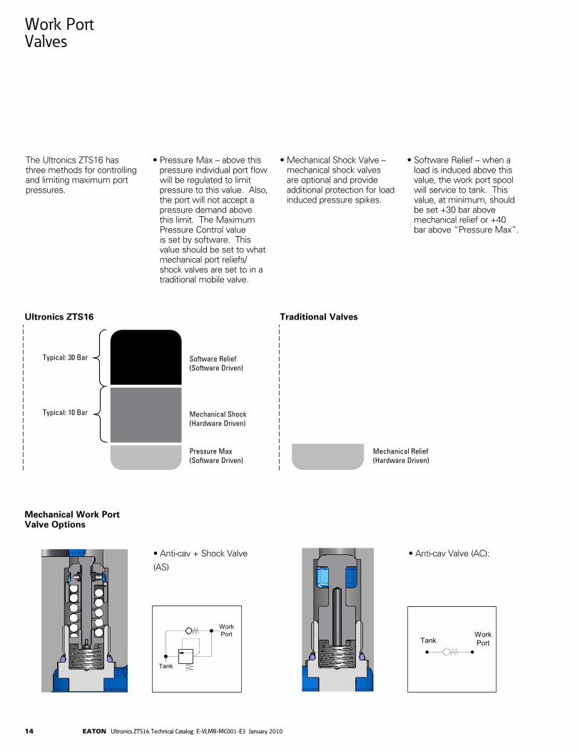
The Ultronics ZTS16 has three methods for controlling and limiting maximum port pressures.
• Pressure Max – above this pressure individual port flow will be regulated to limit pressure to this value. Also, the port will not accept a pressure demand above this limit. The Maximum Pressure Control value is set by software. This value should be set to what mechanical port reliefs/shock valves are set to in a traditional mobile valve.
• Mechanical Shock Valve – mechanical shock valves are optional and provide additional protection for load induced pressure spikes.
• Software Relief – when a load is induced above this value, the work port spool will service to tank. This value, at minimum, should be set +30 bar above mechanical relief or +40 bar above “Pressure Max”.
Ultronics Traditional Valves
Typical – 10 Bar
Typical – 10 Bar
Pressure Relief
Mechanical Shock
Pressure Max Mechanical Relief
Mechanical Work Port Valve Options
Ultronics ZTS16 Traditional Valves
Software Relief (Software Driven)
Typical: 30 Bar
Typical: 10 Bar Mechanical Shock (Hardware Driven)
Pressure Max (Software Driven)
Mechanical Relief (Hardware Driven)
WorkPortTank
• Anti-cav + Shock Valve
(AS)
• Anti-cav Valve (AC):
WorkPort
Tank

15EATON Ultronics ZTS16 Technical Catalog E-VLMB-MC001-E3 January 2010
Manual Override
Manual override is not an alternative mode of manual actuation.
Note:Lever- Handle Override
(L1 = handle on side 1; L2 = handle on side 2)
Single-Spool Override
(S1 = side 1; S2 = side 2; S3 = both sides*)
This is the minimum clear-ance required for operation of the manual override levers. Note that levers do not move during normal operation of the valve.
Operation: Pull handle to engage and operate manual over-ride. Moving the lever “up” will port fluid from P to P1, and from P2 to tank. Moving lever “down” will port fluid from P to P2, and from P1 to tank.
Operation: A captive hexagon nut on the spindle will drive towards the spool when the spindle is turned. This pushes the spool towards the tank only. If spool is biased to pres-sure, fluid will be relieved to service port then tank. If spool is biased to center, fluid will be relieved to tank. (If spool is biased to tank, fluid is already relieved to tank).
* This is possible if each spool is acting as a single service for supply and return (i.e. spring return ram)
7°
7°
Pull for two-spool operation
5-7mm
192.
80

16 EATON Ultronics ZTS16 Technical Catalog E-VLMB-MC001-E3 January 2010
CAN Bus Terminator Assembly Part Numbers Description
2059-030-00L 120 ohm CAN Bus terminator
14-Way Connector (AMP Plug) Part Numbers Description
9615-091-BKM Black 14-way plug assembly kit (VSM) 9615-092-GKY Grey 14-way plug assembly kit (VSE)
Interbank Connection Cables
Interbank Connection Cables Part Numbers Description
2063-001-200 2.0 meter interconnection cable 2063-001-400 4.0 meter interconnection cableNote: If more than one cable is used in a single daisy chain with multiple valve banks, then the combined lengths must be < = 4m.
Interbank Connection Cable

17EATON Ultronics ZTS16 Technical Catalog E-VLMB-MC001-E3 January 2010
114
48,50
57,5
0
27
27
0
AMPSEAL 14-WAY CONNECTOR
P3 PORTAlternative Supply Port (Supplied Plugged)
4 MOUNTING HOLESM8 x 22 Deep
85,5
MAX
With
out
Relie
F Va
lve
89,5
0 M
AXW
ith R
elie
f Val
ve
86 M
AX
57
78 R
EFDi
men
sion
F
127
REF
Dim
ensi
on E
176
REF
Dim
ensi
on D
323
REF
Dim
ensi
on A
225
REF
Dim
ensi
on C
274
REF
Dim
ensi
on B
P1 PORTSupply Inlet from Pump. Alternative ports P2 or P3 may be used to suit installation.
LOAD SENSE PORT(for variable displacment systems ONLY)
T PORTReturn to tank
347 REFMounting Centers
See Table
458 REFOverall Length - See Table
43,5
0
2743
27
18
62,50 48,50PORT A2 PORT B2 PORT C2 PORT D2 PORT E2 PORT F2
PORTS A1 to F1 on other side
P2 PORTAlternative Supply Port(Supplied Plugged)
170,
30 -
See
No
tes
43
MAINSYSTEM RELIEF VALVEPilot Stage
MAIN SYSTEMRELIEF VALVEMain Stage
LOAD SENSE PORTConnect to pump’s LS port using a line of minimum length and volumetric resilience. Air-bleed thoroughly on start-up. Port not present on valves for use with fixed-displacement pumps.
Installation Drawing
Note: All dimensions are in millimeters.
114
48,50
57,5
0
27
27
0
AMPSEAL 14-WAY CONNECTOR
P3 PORTAlternative Supply Port (Supplied Plugged)
4 MOUNTING HOLESM8 x 22 Deep
85,5
MAX
With
out
Relie
F Va
lve
89,5
0 M
AXW
ith R
elie
f Val
ve
86 M
AX
57
78 R
EFDi
men
sion
F
127
REF
Dim
ensi
on E
176
REF
Dim
ensi
on D
323
REF
Dim
ensi
on A
225
REF
Dim
ensi
on C
274
REF
Dim
ensi
on B
P1 PORTSupply Inlet from Pump. Alternative ports P2 or P3 may be used to suit installation.
LOAD SENSE PORT(for variable displacment systems ONLY)
T PORTReturn to tank
347 REFMounting Centers
See Table
458 REFOverall Length - See Table
43,5
0
2743
27
18
62,50 48,50PORT A2 PORT B2 PORT C2 PORT D2 PORT E2 PORT F2
PORTS A1 to F1 on other side
P2 PORTAlternative Supply Port(Supplied Plugged)
170,
30 -
See
No
tes
43
MAINSYSTEM RELIEF VALVEPilot Stage
MAIN SYSTEMRELIEF VALVEMain Stage
LOAD SENSE PORTConnect to pump’s LS port using a line of minimum length and volumetric resilience. Air-bleed thoroughly on start-up. Port not present on valves for use with fixed-displacement pumps.

18 EATON Ultronics ZTS16 Technical Catalog E-VLMB-MC001-E3 January 2010
Installation Drawing
Note: All dimensions are in millimeters.
114
48,50
57,5
0
27
27
0
AMPSEAL 14-WAY CONNECTOR
P3 PORTAlternative Supply Port (Supplied Plugged)
4 MOUNTING HOLESM8 x 22 Deep
85,5
MAX
With
out
Relie
F Va
lve
89,5
0 M
AXW
ith R
elie
f Val
ve
86 M
AX
57
78 R
EFDi
men
sion
F
127
REF
Dim
ensi
on E
176
REF
Dim
ensi
on D
323
REF
Dim
ensi
on A
225
REF
Dim
ensi
on C
274
REF
Dim
ensi
on B
P1 PORTSupply Inlet from Pump. Alternative ports P2 or P3 may be used to suit installation.
LOAD SENSE PORT(for variable displacment systems ONLY)
T PORTReturn to tank
347 REFMounting Centers
See Table
458 REFOverall Length - See Table
43,5
0
2743
27
18
62,50 48,50PORT A2 PORT B2 PORT C2 PORT D2 PORT E2 PORT F2
PORTS A1 to F1 on other side
P2 PORTAlternative Supply Port(Supplied Plugged)
170,
30 -
See
No
tes
43
MAINSYSTEM RELIEF VALVEPilot Stage
MAIN SYSTEMRELIEF VALVEMain Stage
LOAD SENSE PORTConnect to pump’s LS port using a line of minimum length and volumetric resilience. Air-bleed thoroughly on start-up. Port not present on valves for use with fixed-displacement pumps.
114
48,50
57,5
0
27
27
0
AMPSEAL 14-WAY CONNECTOR
P3 PORTAlternative Supply Port (Supplied Plugged)
4 MOUNTING HOLESM8 x 22 Deep
85,5
MAX
With
out
Relie
F Va
lve
89,5
0 M
AXW
ith R
elie
f Val
ve
86 M
AX
57
78 R
EFDi
men
sion
F
127
REF
Dim
ensi
on E
176
REF
Dim
ensi
on D
323
REF
Dim
ensi
on A
225
REF
Dim
ensi
on C
274
REF
Dim
ensi
on B
P1 PORTSupply Inlet from Pump. Alternative ports P2 or P3 may be used to suit installation.
LOAD SENSE PORT(for variable displacment systems ONLY)
T PORTReturn to tank
347 REFMounting Centers
See Table
458 REFOverall Length - See Table
43,5
0
2743
27
18
62,50 48,50PORT A2 PORT B2 PORT C2 PORT D2 PORT E2 PORT F2
PORTS A1 to F1 on other side
P2 PORTAlternative Supply Port(Supplied Plugged)
170,
30 -
See
No
tes
43
MAINSYSTEM RELIEF VALVEPilot Stage
MAIN SYSTEMRELIEF VALVEMain Stage
LOAD SENSE PORTConnect to pump’s LS port using a line of minimum length and volumetric resilience. Air-bleed thoroughly on start-up. Port not present on valves for use with fixed-displacement pumps.
Number of Mounting Overall Dim. Dim. Dim. Dim. Dim. Dim. Valve Sections Centers Length a b c d e f
1 102 213 78 x x x x x2 151 262 127 78 x x x x3 200 311 176 127 78 x x x4 249 360 225 176 127 78 x x5 298 409 274 225 176 127 78 x6 347 458 323 274 225 176 127 78

Eaton Hydraulics Group USA14615 Lone Oak RoadEden Prairie, MN 55344USATel: 952-937-9800Fax: 952-294-7722www.eaton.com/hydraulics
EatonHydraulics Group EuropeRoute de la Longeraie 71110 MorgesSwitzerlandTel: +41 (0) 21 811 4600Fax: +41 (0) 21 811 4601
EatonHydraulics Group Asia PacificEaton Building4th Floor, No. 3 Lane 280 Linhong Rd. Changning DistrictShanghai 200335ChinaTel: (+86 21) 5200 0099Fax: (+86 21) 5200 0400
© 2010 Eaton CorporationAll Rights Reserved Printed in USADocument No. E-VLMB-MC001-E3Supersedes E-VLMB-MC001-E2 January 2010