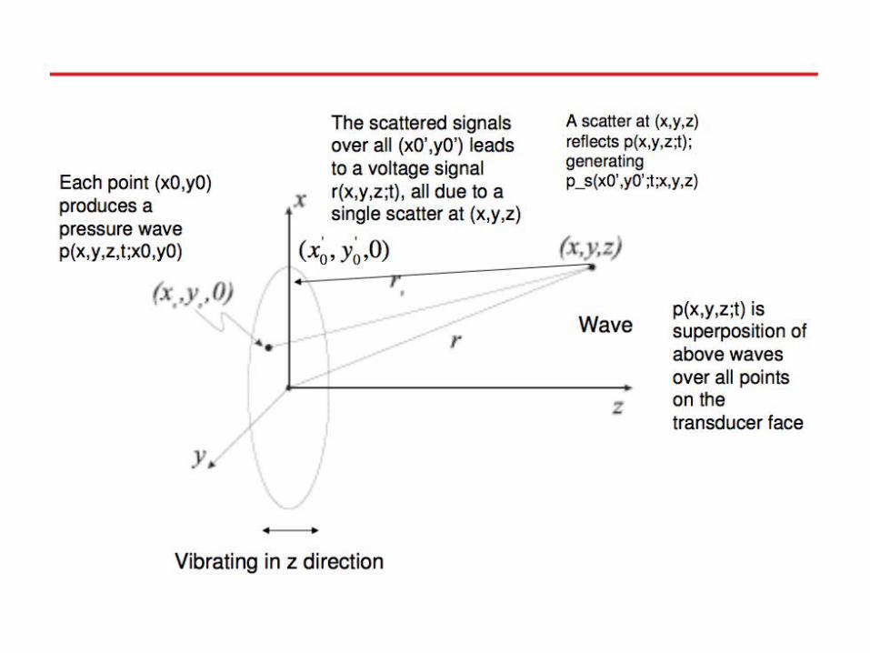
Ultrasonic İmaging. Ultrasound – The propagating media interaction 2 Scattering (Uniform and..)...
20
Ultrasonic İmaging
-
Upload
marion-fowler -
Category
Documents
-
view
232 -
download
2
Transcript of Ultrasonic İmaging. Ultrasound – The propagating media interaction 2 Scattering (Uniform and..)...
Ultrasonic İmaging

Ultrasound – The propagating media interaction
2
• Scattering (Uniform and ..)
• Reflection
• Refraction
• Absorbtion
• The reflected wave from a boundary deviates,
• Cannot be interpreted as reflection or refraction
• The Phenemenon is called as diffraction
• Huygens principle expresses diffraction
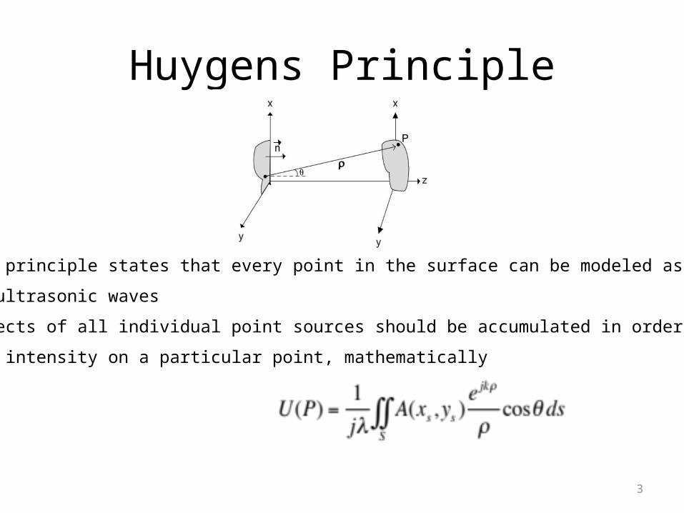
Huygens Principle
3
• Huygens principle states that every point in the surface can be modeled as a source
emitting ultrasonic waves
• The effects of all individual point sources should be accumulated in order to determine
The field intensity on a particular point, mathematically

Beam Pattern
4
• Rearrange field intensity at P point using paraxial, fresnel and fraunhofer approximations,
• Result is important because it states that the far-field intensity is the fourier transform
of aperture function; kx/z and ky/z are spatial frequencies
• U(P) shows far-field beam pattern of A(x,y) and it defines the beam quality
• Wider apertures results narrower beams, thus aperture size affects beam width
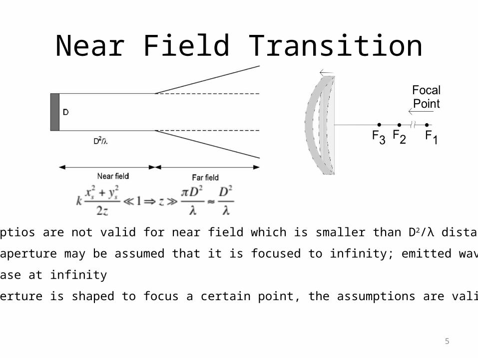
Near Field Transition
5
• The assumptios are not valid for near field which is smaller than D2/λ distant
• The flat aperture may be assumed that it is focused to infinity; emitted waves have
the same phase at infinity
• If the aperture is shaped to focus a certain point, the assumptions are valid at that point

Pulse-Echo
6
• Some imaging systems rotates the transducer in order to steer its receive/transmit beam
• Transducer transmits US signal to the each angle in imaging area and receives the
reflected signal, The TX/RX operation is known as pulse echo
• Echo carries impedance information of corresponding steering angle


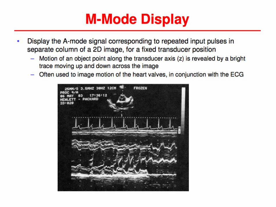


C-Mode Display
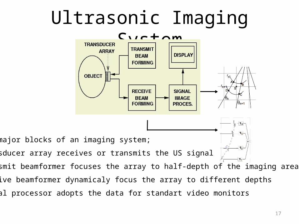
Ultrasonic Imaging System
17
• The major blocks of an imaging system;
• Transducer array receives or transmits the US signal
• Transmit beamformer focuses the array to half-depth of the imaging area
• Receive beamformer dynamicaly focus the array to different depths
• Signal processor adopts the data for standart video monitors

Sampled Transducer (Array)
18
• Single transducer enables fixed focused or not focused operation. That disables in-phase
sum of signals out of focal point.
• Instead of single mechanical focus transducer can be sampled in order to form a
transducer array, which enables multiple focus by applying proper delays

Steering and Focusing
19
• Multiple focal zones are possible using an array.
• Multiple transmit focus is not practical; dynamic focusing is employed only in receive mode
• The beamforming can mathetmatically be expressed as follows,
, , where s(.) is input signal,
τ is beamforming delays, c is velocity of US, F is focal distance and b(t) is beamformed signal

Beamforming Techniques
20
• Full Phased Array
• All array elements simultaneously activated for transmit and receive
• Requires complex front-end electronics
• Improved SNR, Proportional with N√N
• Classical Synthetic Aperture
• The same element is activated for transmit and receive
• Simple front end
• Poor SNR, Proporional with
• Synthetic Phased Array
• All array element pairs individually activated using multiple pulse-echo
• Average SNR