UltraCW Automatic Cell Washing System Operation Manual · Automatic Cell Washing System Operation...
50
HELMER SCIENTIFIC 14400 Bergen Boulevard Noblesville, IN 46060 USA PH +1.317.773.9073 FAX +1.317.773.9082 USA and Canada 800.743.5637 ISO 13485:2003 CERTIFIED TM Automatic Cell Washing System Operation Manual Model Version UltraCW™ B 360084-1/O
Transcript of UltraCW Automatic Cell Washing System Operation Manual · Automatic Cell Washing System Operation...
HELMER SCIENTIFIC14400 Bergen BoulevardNoblesville, IN 46060 USA
PH +1.317.773.9073FAX +1.317.773.9082USA and Canada 800.743.5637
ISO 13485:2003 CERTIFIED
TM
Automatic Cell Washing System Operation Manual
Model VersionUltraCW™ B
360084-1/O
i
360084-1/O
Document HistoryRevision Date CO Supersession Revision Description
M 05 SEP 2013* 8686 M supersedes F, G, H, I, J, K, L Revised layout for ease of navigation and locating information.
N 07 FEB 2014* 9132 N supersedes M
► Defined safety statements according to ANSI Z535.4 standards.
► Added caution statements as suggested by cell washer manufacturer (pages 12 and 34).
► Corrected Example 2 in section 10.2.
O 05 JUN 2014* 9553 O supersedes N► Corrected typographical error in section 10.2.► Added instructions for installation of transport bolts, prior to
moving/shipping the cell washer.
* Date submitted for Change Order review. Actual release date may vary.
ii
360084-1/O
Contents
Section I: General Information . . . . . . . . . . . . . . . . . . . . . . . . . . . . . . . . . . . . . . . . 51 About this Manual . . . . . . . . . . . . . . . . . . . . . . . . . . . . . . . . . . . . . . . . . . . . . . . . . . . . . . . . . . 5
1.1 Intended Audience. . . . . . . . . . . . . . . . . . . . . . . . . . . . . . . . . . . . . . . . . . . . . . . . . . . . . . . . . . . . . . . . . . . . . . 51.2 Model References . . . . . . . . . . . . . . . . . . . . . . . . . . . . . . . . . . . . . . . . . . . . . . . . . . . . . . . . . . . . . . . . . . . . . . 51.3 Copyright and Trademark . . . . . . . . . . . . . . . . . . . . . . . . . . . . . . . . . . . . . . . . . . . . . . . . . . . . . . . . . . . . . . . . 5
2 Safety . . . . . . . . . . . . . . . . . . . . . . . . . . . . . . . . . . . . . . . . . . . . . . . . . . . . . . . . . . . . . . . . . . . . 52.1 Safety Definitions . . . . . . . . . . . . . . . . . . . . . . . . . . . . . . . . . . . . . . . . . . . . . . . . . . . . . . . . . . . . . . . . . . . . . . 52.2 Product Labels . . . . . . . . . . . . . . . . . . . . . . . . . . . . . . . . . . . . . . . . . . . . . . . . . . . . . . . . . . . . . . . . . . . . . . . . 52.3 Avoiding Injury . . . . . . . . . . . . . . . . . . . . . . . . . . . . . . . . . . . . . . . . . . . . . . . . . . . . . . . . . . . . . . . . . . . . . . . . . 6
3 General Recommendations . . . . . . . . . . . . . . . . . . . . . . . . . . . . . . . . . . . . . . . . . . . . . . . . . . . 63.1 Intended Use . . . . . . . . . . . . . . . . . . . . . . . . . . . . . . . . . . . . . . . . . . . . . . . . . . . . . . . . . . . . . . . . . . . . . . . . . . 63.2 General Use . . . . . . . . . . . . . . . . . . . . . . . . . . . . . . . . . . . . . . . . . . . . . . . . . . . . . . . . . . . . . . . . . . . . . . . . . . 6
4 Specifications . . . . . . . . . . . . . . . . . . . . . . . . . . . . . . . . . . . . . . . . . . . . . . . . . . . . . . . . . . . . . . 7
5 Compliance . . . . . . . . . . . . . . . . . . . . . . . . . . . . . . . . . . . . . . . . . . . . . . . . . . . . . . . . . . . . . . . . 85.1 Regulatory Compliance . . . . . . . . . . . . . . . . . . . . . . . . . . . . . . . . . . . . . . . . . . . . . . . . . . . . . . . . . . . . . . . . . . 85.2 WEEE Compliance . . . . . . . . . . . . . . . . . . . . . . . . . . . . . . . . . . . . . . . . . . . . . . . . . . . . . . . . . . . . . . . . . . . . . 8
6 Installation . . . . . . . . . . . . . . . . . . . . . . . . . . . . . . . . . . . . . . . . . . . . . . . . . . . . . . . . . . . . . . . . 86.1 Location Requirements . . . . . . . . . . . . . . . . . . . . . . . . . . . . . . . . . . . . . . . . . . . . . . . . . . . . . . . . . . . . . . . . . . 8
6.1.1 Placement . . . . . . . . . . . . . . . . . . . . . . . . . . . . . . . . . . . . . . . . . . . . . . . . . . . . . . . . . . . . . . . . . . . . . 8
7 Maintenance Schedule . . . . . . . . . . . . . . . . . . . . . . . . . . . . . . . . . . . . . . . . . . . . . . . . . . . . . . 9
SectionII:Configuration . . . . . . . . . . . . . . . . . . . . . . . . . . . . . . . . . . . . . . . . . . . . 108 Cell Washer Installation . . . . . . . . . . . . . . . . . . . . . . . . . . . . . . . . . . . . . . . . . . . . . . . . . . . . . 10
8.1 Remove Packaging Materials . . . . . . . . . . . . . . . . . . . . . . . . . . . . . . . . . . . . . . . . . . . . . . . . . . . . . . . . . . . . 108.2 Remove Transport Bolts . . . . . . . . . . . . . . . . . . . . . . . . . . . . . . . . . . . . . . . . . . . . . . . . . . . . . . . . . . . . . . . . 108.3 Install Transport Bolts . . . . . . . . . . . . . . . . . . . . . . . . . . . . . . . . . . . . . . . . . . . . . . . . . . . . . . . . . . . . . . . . . . 118.4 Connect the Saline and Drain Tubes. . . . . . . . . . . . . . . . . . . . . . . . . . . . . . . . . . . . . . . . . . . . . . . . . . . . . . . 11
8.4.1 Install Saline Supply Tubing . . . . . . . . . . . . . . . . . . . . . . . . . . . . . . . . . . . . . . . . . . . . . . . . . . . . . . . 118.4.2 Install Drain Tubing . . . . . . . . . . . . . . . . . . . . . . . . . . . . . . . . . . . . . . . . . . . . . . . . . . . . . . . . . . . . . . 118.4.3 Connect the Cell Washer to the Saline Supply . . . . . . . . . . . . . . . . . . . . . . . . . . . . . . . . . . . . . . . . 128.4.4 Connect the Cell Washer to the Drain . . . . . . . . . . . . . . . . . . . . . . . . . . . . . . . . . . . . . . . . . . . . . . . 128.4.5 Remove Saline Supply Tubing or Drain Tubing . . . . . . . . . . . . . . . . . . . . . . . . . . . . . . . . . . . . . . . . 12
8.5 Initial Start Up . . . . . . . . . . . . . . . . . . . . . . . . . . . . . . . . . . . . . . . . . . . . . . . . . . . . . . . . . . . . . . . . . . . . . . . . 128.6 Open and Close the Lid. . . . . . . . . . . . . . . . . . . . . . . . . . . . . . . . . . . . . . . . . . . . . . . . . . . . . . . . . . . . . . . . . 138.7 Release the Lid Lock . . . . . . . . . . . . . . . . . . . . . . . . . . . . . . . . . . . . . . . . . . . . . . . . . . . . . . . . . . . . . . . . . . . 14
9 Rotor Installation . . . . . . . . . . . . . . . . . . . . . . . . . . . . . . . . . . . . . . . . . . . . . . . . . . . . . . . . . . 159.1 Install and Remove the Rotor . . . . . . . . . . . . . . . . . . . . . . . . . . . . . . . . . . . . . . . . . . . . . . . . . . . . . . . . . . . . 159.2 Select the Rotor Type . . . . . . . . . . . . . . . . . . . . . . . . . . . . . . . . . . . . . . . . . . . . . . . . . . . . . . . . . . . . . . . . . . 159.3 Balance the Rotor . . . . . . . . . . . . . . . . . . . . . . . . . . . . . . . . . . . . . . . . . . . . . . . . . . . . . . . . . . . . . . . . . . . . . 169.4 Install and Remove Tube Holder Inserts . . . . . . . . . . . . . . . . . . . . . . . . . . . . . . . . . . . . . . . . . . . . . . . . . . . . 179.5 Load Tubes . . . . . . . . . . . . . . . . . . . . . . . . . . . . . . . . . . . . . . . . . . . . . . . . . . . . . . . . . . . . . . . . . . . . . . . . . . 18
iii
360084-1/O
10 Calibrate Saline Volume . . . . . . . . . . . . . . . . . . . . . . . . . . . . . . . . . . . . . . . . . . . . . . . . . . . . 1810.1 Dispense and Measure Saline Volume . . . . . . . . . . . . . . . . . . . . . . . . . . . . . . . . . . . . . . . . . . . . . . . . . . . . . 1810.2 Determine Saline Volume Adjustment . . . . . . . . . . . . . . . . . . . . . . . . . . . . . . . . . . . . . . . . . . . . . . . . . . . . . . 1910.3 Change the Saline Volume . . . . . . . . . . . . . . . . . . . . . . . . . . . . . . . . . . . . . . . . . . . . . . . . . . . . . . . . . . . . . . 20
11 Components . . . . . . . . . . . . . . . . . . . . . . . . . . . . . . . . . . . . . . . . . . . . . . . . . . . . . . . . . . . . . . 2111.1 Front, Lid, and Bowl . . . . . . . . . . . . . . . . . . . . . . . . . . . . . . . . . . . . . . . . . . . . . . . . . . . . . . . . . . . . . . . . . . . 2111.2 Control Panel. . . . . . . . . . . . . . . . . . . . . . . . . . . . . . . . . . . . . . . . . . . . . . . . . . . . . . . . . . . . . . . . . . . . . . . . . 2211.3 Rotor . . . . . . . . . . . . . . . . . . . . . . . . . . . . . . . . . . . . . . . . . . . . . . . . . . . . . . . . . . . . . . . . . . . . . . . . . . . . . . . 2311.4 Side . . . . . . . . . . . . . . . . . . . . . . . . . . . . . . . . . . . . . . . . . . . . . . . . . . . . . . . . . . . . . . . . . . . . . . . . . . . . . . . . 2311.5 Rear . . . . . . . . . . . . . . . . . . . . . . . . . . . . . . . . . . . . . . . . . . . . . . . . . . . . . . . . . . . . . . . . . . . . . . . . . . . . . . . . 24
Section III: Programming . . . . . . . . . . . . . . . . . . . . . . . . . . . . . . . . . . . . . . . . . . . 2512 Processes and Process Steps . . . . . . . . . . . . . . . . . . . . . . . . . . . . . . . . . . . . . . . . . . . . . . . 25
12.1 Processes . . . . . . . . . . . . . . . . . . . . . . . . . . . . . . . . . . . . . . . . . . . . . . . . . . . . . . . . . . . . . . . . . . . . . . . . . . . 2512.2 Process Steps . . . . . . . . . . . . . . . . . . . . . . . . . . . . . . . . . . . . . . . . . . . . . . . . . . . . . . . . . . . . . . . . . . . . . . . . 26
12.2.1 Fill Step . . . . . . . . . . . . . . . . . . . . . . . . . . . . . . . . . . . . . . . . . . . . . . . . . . . . . . . . . . . . . . . . . . . . . . 2612.2.2 Spin Step . . . . . . . . . . . . . . . . . . . . . . . . . . . . . . . . . . . . . . . . . . . . . . . . . . . . . . . . . . . . . . . . . . . . . 2612.2.3 Decant Step . . . . . . . . . . . . . . . . . . . . . . . . . . . . . . . . . . . . . . . . . . . . . . . . . . . . . . . . . . . . . . . . . . . 2712.2.4 Drop Spin-Down Step . . . . . . . . . . . . . . . . . . . . . . . . . . . . . . . . . . . . . . . . . . . . . . . . . . . . . . . . . . . . 2712.2.5 Agitation Step . . . . . . . . . . . . . . . . . . . . . . . . . . . . . . . . . . . . . . . . . . . . . . . . . . . . . . . . . . . . . . . . . . 2712.2.6 Suspension Step . . . . . . . . . . . . . . . . . . . . . . . . . . . . . . . . . . . . . . . . . . . . . . . . . . . . . . . . . . . . . . . 2812.2.7 Suspension-Agitation Step . . . . . . . . . . . . . . . . . . . . . . . . . . . . . . . . . . . . . . . . . . . . . . . . . . . . . . . . 28
13 Programs and Parameters . . . . . . . . . . . . . . . . . . . . . . . . . . . . . . . . . . . . . . . . . . . . . . . . . . 2913.1 Display Mode. . . . . . . . . . . . . . . . . . . . . . . . . . . . . . . . . . . . . . . . . . . . . . . . . . . . . . . . . . . . . . . . . . . . . . . . . 2913.2 Global Parameters . . . . . . . . . . . . . . . . . . . . . . . . . . . . . . . . . . . . . . . . . . . . . . . . . . . . . . . . . . . . . . . . . . . . 29
13.2.1 View and Change Global Parameters . . . . . . . . . . . . . . . . . . . . . . . . . . . . . . . . . . . . . . . . . . . . . . . 3113.3 Programs and Program Parameters . . . . . . . . . . . . . . . . . . . . . . . . . . . . . . . . . . . . . . . . . . . . . . . . . . . . . . . 31
13.3.1 Programs . . . . . . . . . . . . . . . . . . . . . . . . . . . . . . . . . . . . . . . . . . . . . . . . . . . . . . . . . . . . . . . . . . . . . 3213.3.2 Program Parameters . . . . . . . . . . . . . . . . . . . . . . . . . . . . . . . . . . . . . . . . . . . . . . . . . . . . . . . . . . . . 3213.3.3 Select a Program . . . . . . . . . . . . . . . . . . . . . . . . . . . . . . . . . . . . . . . . . . . . . . . . . . . . . . . . . . . . . . . 3313.3.4 View Parameter Summary for a Selected Program . . . . . . . . . . . . . . . . . . . . . . . . . . . . . . . . . . . . . 3413.3.5 View all Program Parameters for a Selected Program . . . . . . . . . . . . . . . . . . . . . . . . . . . . . . . . . . . 3413.3.6 Change Program Parameters . . . . . . . . . . . . . . . . . . . . . . . . . . . . . . . . . . . . . . . . . . . . . . . . . . . . . 35
Section IV: Operation . . . . . . . . . . . . . . . . . . . . . . . . . . . . . . . . . . . . . . . . . . . . . . 3614 Start and Stop Processes . . . . . . . . . . . . . . . . . . . . . . . . . . . . . . . . . . . . . . . . . . . . . . . . . . . 36
14.1 Start a Process . . . . . . . . . . . . . . . . . . . . . . . . . . . . . . . . . . . . . . . . . . . . . . . . . . . . . . . . . . . . . . . . . . . . . . . 3614.2 Stop a Process . . . . . . . . . . . . . . . . . . . . . . . . . . . . . . . . . . . . . . . . . . . . . . . . . . . . . . . . . . . . . . . . . . . . . . . 3714.3 Pause and Resume a Process . . . . . . . . . . . . . . . . . . . . . . . . . . . . . . . . . . . . . . . . . . . . . . . . . . . . . . . . . . . 3714.4 Audible Alerts for Process Completion . . . . . . . . . . . . . . . . . . . . . . . . . . . . . . . . . . . . . . . . . . . . . . . . . . . . . 38
15 Sample Programs . . . . . . . . . . . . . . . . . . . . . . . . . . . . . . . . . . . . . . . . . . . . . . . . . . . . . . . . . . 3815.1 Sample Single-Cycle Washing Process . . . . . . . . . . . . . . . . . . . . . . . . . . . . . . . . . . . . . . . . . . . . . . . . . . . . 3915.2 Sample Multiple-Cycle Washing Process . . . . . . . . . . . . . . . . . . . . . . . . . . . . . . . . . . . . . . . . . . . . . . . . . . . 4015.3 Sample Suspension-Only Process . . . . . . . . . . . . . . . . . . . . . . . . . . . . . . . . . . . . . . . . . . . . . . . . . . . . . . . . 4115.4 Sample Suspension with Agitation Process . . . . . . . . . . . . . . . . . . . . . . . . . . . . . . . . . . . . . . . . . . . . . . . . . 4215.5 Sample Spinning-Only Process. . . . . . . . . . . . . . . . . . . . . . . . . . . . . . . . . . . . . . . . . . . . . . . . . . . . . . . . . . . 43
iv
360084-1/O
15.6 Sample Spinning with Decanting Process. . . . . . . . . . . . . . . . . . . . . . . . . . . . . . . . . . . . . . . . . . . . . . . . . . . 4415.7 Sample Spinning After Agitation Process . . . . . . . . . . . . . . . . . . . . . . . . . . . . . . . . . . . . . . . . . . . . . . . . . . . 4515.8 Sample Agitation-Only Process . . . . . . . . . . . . . . . . . . . . . . . . . . . . . . . . . . . . . . . . . . . . . . . . . . . . . . . . . . . 46
15.8.1 Sample Agitation-Only Process (Started with the START WASH Button) . . . . . . . . . . . . . . . . . . . . 4615.8.2 Sample Agitation-Only Process (Started with the SPIN Button) . . . . . . . . . . . . . . . . . . . . . . . . . . . . 47
5
General Information
360084-1/O
Section I: General Information
1 About this Manual
1 .1 Intended Audience
This manual is intended for use by end users of the UltraCW™ automatic cell washing system and authorized service technicians.
1 .2 Model References
Generic references are used throughout this manual to group models that contain similar features. For example, “UltraCW” refers to both the 115 V and 230 V models. If a feature or procedure applies to a specific voltage, it is stated as such.
1 .3 Copyright and Trademark
Helmer® and UltraCW are registered trademarks or trademarks of Helmer, Inc. in the United States of America. Copyright © 2014 Helmer, Inc. All other trademarks and registered trademarks are the property of their respective owners.
Helmer, Inc., doing business as (DBA) Helmer Scientific and Helmer.
2 SafetyThe operator or technician performing maintenance or service on Helmer Scientific products must (a) inspect the product for abnormal wear and damage, (b) choose a repair procedure which will not endanger his/her safety, the safety of others, the product, or the safe operation of the product, and (c) fully inspect and test the product to ensure the maintenance or service has been performed properly.
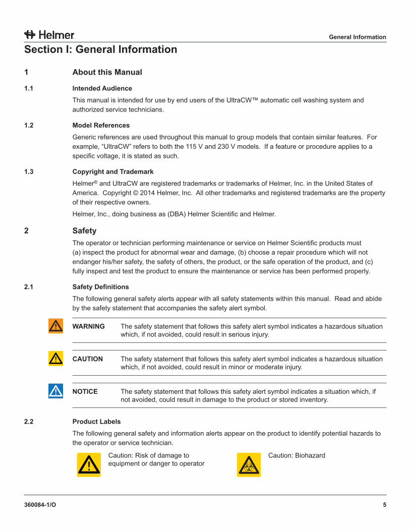
2.1 SafetyDefinitions
The following general safety alerts appear with all safety statements within this manual. Read and abide by the safety statement that accompanies the safety alert symbol.
WARNING The safety statement that follows this safety alert symbol indicates a hazardous situation which, if not avoided, could result in serious injury.
CAUTION The safety statement that follows this safety alert symbol indicates a hazardous situation which, if not avoided, could result in minor or moderate injury.
NOTICE The safety statement that follows this safety alert symbol indicates a situation which, if not avoided, could result in damage to the product or stored inventory.
2 .2 Product Labels
The following general safety and information alerts appear on the product to identify potential hazards to the operator or service technician.
Caution: Risk of damage to equipment or danger to operator
Caution: Biohazard
6
General Information
360084-1/O
2 .3 Avoiding Injury► Review safety instructions before installing, using, or maintaining the equipment.► Do not move or bump the cell washer during operation.► Before moving unit, disconnect the AC power cord and secure the cord.► Never physically restrict any moving component.► Avoid removing electrical service panels and access panels unless so instructed.► Use supplied power cords only.► Using the equipment in a manner not specified by Helmer may impair the protection provided by the
equipment.► Decontaminate parts prior to sending for service or repair. Contact Helmer or your distributor for
decontamination instructions and a Return Authorization Number.
3 General Recommendations
3 .1 Intended Use
The Helmer UltraCW™ cell washing system is intended for use in blood banking and other laboratory procedures.
3 .2 General Use
Allow the cell washer to come to room temperature before switching power on.
7
General Information
360084-1/O
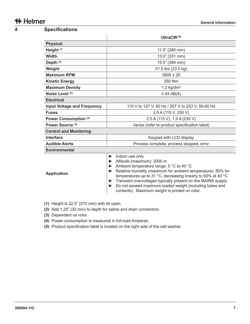
4 SpecificationsUltraCW™
PhysicalHeight (1) 11.0” (280 mm)Width 13.0” (331 mm)Depth (2) 15.5” (394 mm)Weight 51.5 lbs (23.5 kg)Maximum RPM 3500 ± 20Kinetic Energy 250 NmMaximum Density 1.2 kg/dm³Noise Level (3) ≤ 44 dB(A)ElectricalInput Voltage and Frequency 110 V to 127 V, 60 Hz / 207 V to 253 V, 50-60 HzFuses 2.5 A (115 V, 230 V)Power Consumption (4) 2.5 A (115 V), 1.5 A (230 V)Power Source (5) Varies (refer to product specification label)Control and MonitoringInterface Keypad with LCD displayAudible Alerts Process complete, process stopped, errorEnvironmental
Application
► Indoor use only► Altitude (maximum): 2000 m► Ambient temperature range: 5 °C to 40 °C► Relative humidity (maximum for ambient temperature): 80% for
temperatures up to 31 °C, decreasing linearly to 50% at 40 °C► Transient overvoltages typically present on the MAINS supply► Do not exceed maximum loaded weight (including tubes and
contents). Maximum weight is printed on rotor.
(1) Height is 22.5” (572 mm) with lid open.(2) Add 1.25” (32 mm) to depth for saline and drain connectors.(3) Dependent on rotor.(4) Power consumption is measured in full-load Amperes.(5) Product specification label is located on the right side of the cell washer.
8
General Information
360084-1/O
5 Compliance
5 .1 Regulatory Compliance
Pollution degree: 2 (for use in USA and Canada only)
This product is certified to applicable UL and CSA standards by a NRTL.
Sound level (dependent on rotor): ≤ 44 dB(A)
5 .2 WEEE Compliance
The WEEE (waste electrical and electronic equipment) symbol (right) indicates compliance with European Union Directive WEEE 2002/96/EC and applicable provisions. The directive sets requirements for labeling and disposal of certain products in affected countries.
When disposing of this product in countries affected by this directive:► Do not dispose of this product as unsorted municipal waste.► Collect this product separately.► Use collection and return systems available locally.
For more information on the return, recovery, or recycling of this product, contact your local distributor.
6 Installation
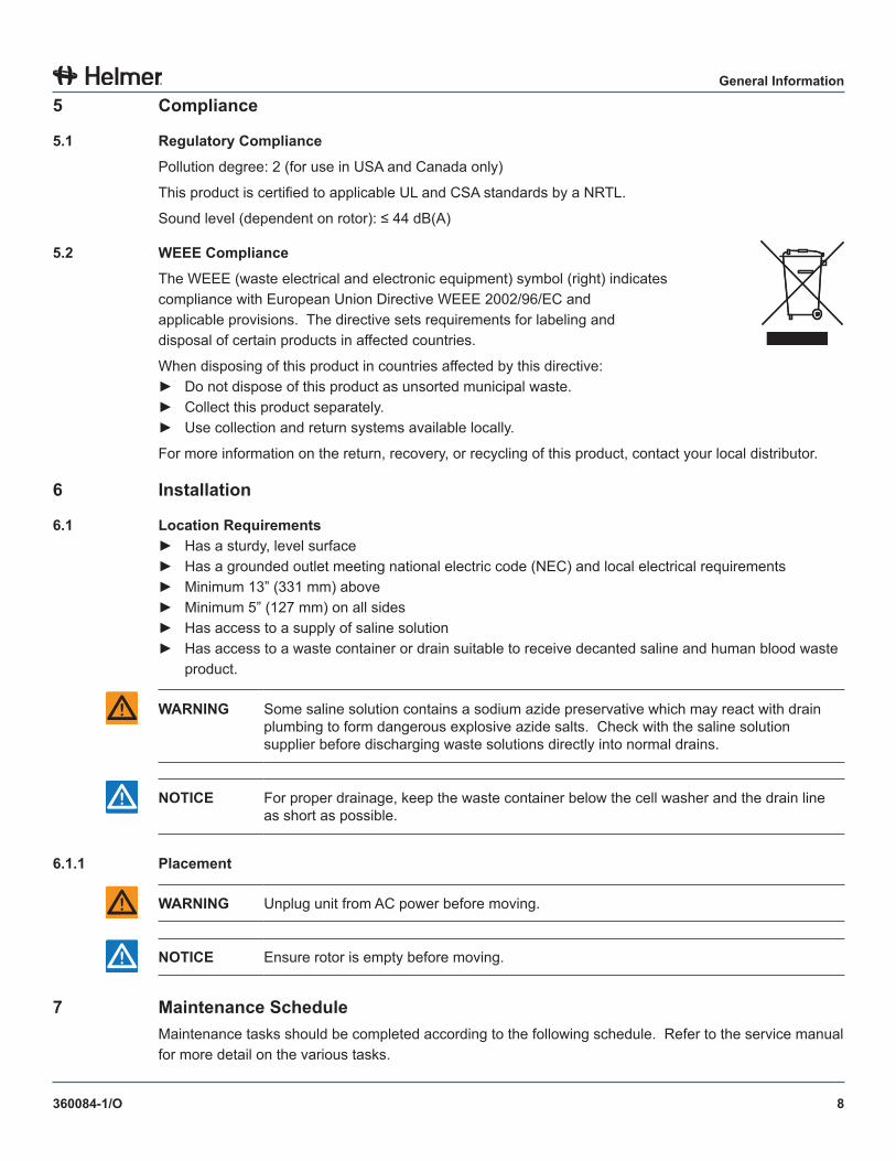
6 .1 Location Requirements► Has a sturdy, level surface► Has a grounded outlet meeting national electric code (NEC) and local electrical requirements► Minimum 13” (331 mm) above► Minimum 5” (127 mm) on all sides► Has access to a supply of saline solution► Has access to a waste container or drain suitable to receive decanted saline and human blood waste
product.
WARNING Some saline solution contains a sodium azide preservative which may react with drain plumbing to form dangerous explosive azide salts. Check with the saline solution supplier before discharging waste solutions directly into normal drains.
NOTICE For proper drainage, keep the waste container below the cell washer and the drain line as short as possible.
6 .1 .1 Placement
WARNING Unplug unit from AC power before moving.
NOTICE Ensure rotor is empty before moving.
7 Maintenance ScheduleMaintenance tasks should be completed according to the following schedule. Refer to the service manual for more detail on the various tasks.
9
General Information
360084-1/O
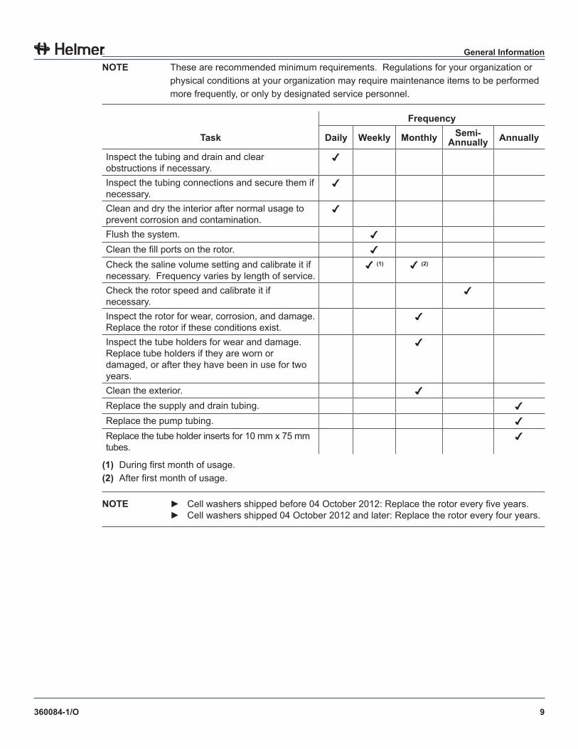
NOTE These are recommended minimum requirements. Regulations for your organization or physical conditions at your organization may require maintenance items to be performed more frequently, or only by designated service personnel.
Frequency
Task Daily Weekly Monthly Semi-Annually Annually
Inspect the tubing and drain and clear obstructions if necessary.
Inspect the tubing connections and secure them if necessary.
Clean and dry the interior after normal usage to prevent corrosion and contamination.
Flush the system.
Clean the fill ports on the rotor.
Check the saline volume setting and calibrate it if necessary. Frequency varies by length of service.
(1) (2)
Check the rotor speed and calibrate it if necessary.
Inspect the rotor for wear, corrosion, and damage. Replace the rotor if these conditions exist.
Inspect the tube holders for wear and damage. Replace tube holders if they are worn or damaged, or after they have been in use for two years.
Clean the exterior.
Replace the supply and drain tubing.
Replace the pump tubing.
Replace the tube holder inserts for 10 mm x 75 mm tubes.
(1) During first month of usage.(2) After first month of usage.
NOTE ► Cell washers shipped before 04 October 2012: Replace the rotor every five years.► Cell washers shipped 04 October 2012 and later: Replace the rotor every four years.
10
Configuration
360084-1/O
SectionII:Configuration
8 Cell Washer Installation
8 .1 Remove Packaging Materials
Before using the cell washer, open the lid and remove all packaging materials from the rotor and bowl.
NOTE Keep the packaging materials for future use.
8 .2 Remove Transport Bolts
The transport bolts are located on the bottom of the cell washer. Transport bolts prevent the motor from moving during shipping, and must be removed prior to use.
The transport bolt removal tool is needed to perform this procedure. The tool is included but packaged separately from the cell washer.
NOTICE ► Keep the transport bolts and removal tool for future use.► Do not tip the cell washer on its back or side while removing the transport bolts.
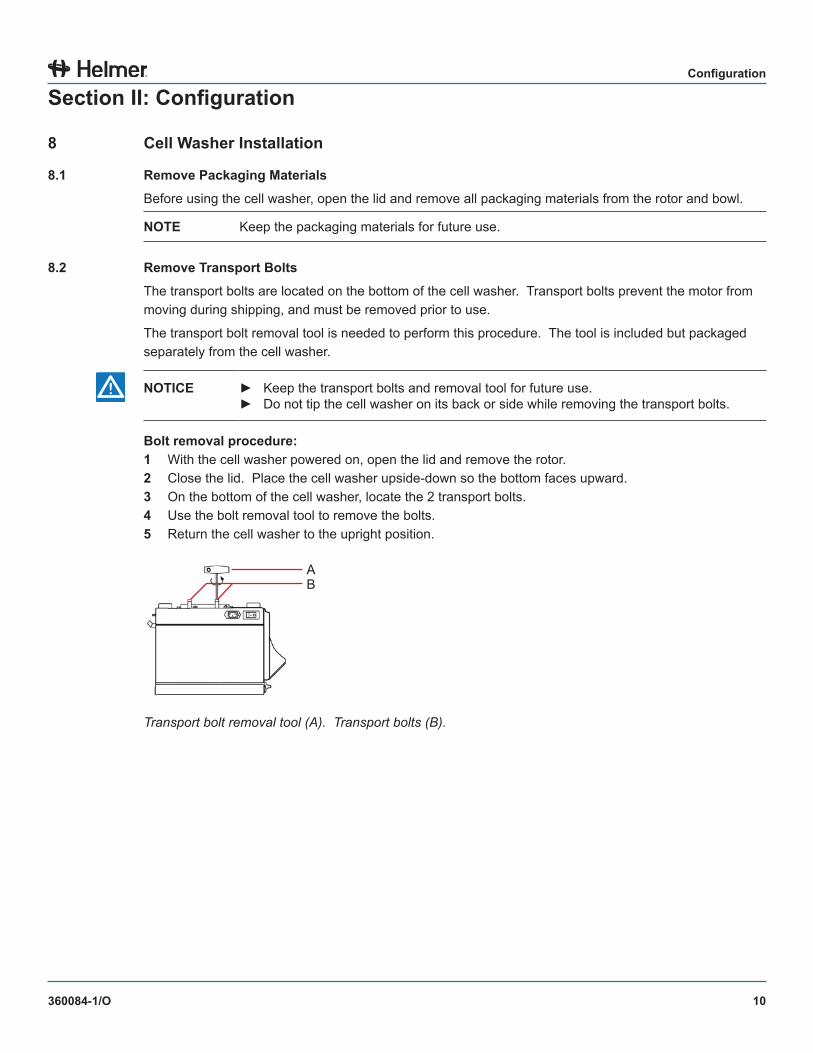
Bolt removal procedure:1 With the cell washer powered on, open the lid and remove the rotor.2 Close the lid. Place the cell washer upside-down so the bottom faces upward.3 On the bottom of the cell washer, locate the 2 transport bolts.4 Use the bolt removal tool to remove the bolts.5 Return the cell washer to the upright position.
AB
Transport bolt removal tool (A). Transport bolts (B).
11
Configuration
360084-1/O
8 .3 Install Transport Bolts
Transport bolts prevent the motor from moving during shipping, and must be installed prior to moving or shipping the cell washer.
The transport bolt removal tool is needed to perform this procedure. The tool is included but packaged separately from the cell washer.
NOTICE ► The transport bolts must be installed prior to moving or shipping the cell washer.► Do not tip the cell washer on its back or side while installing the transport bolts.
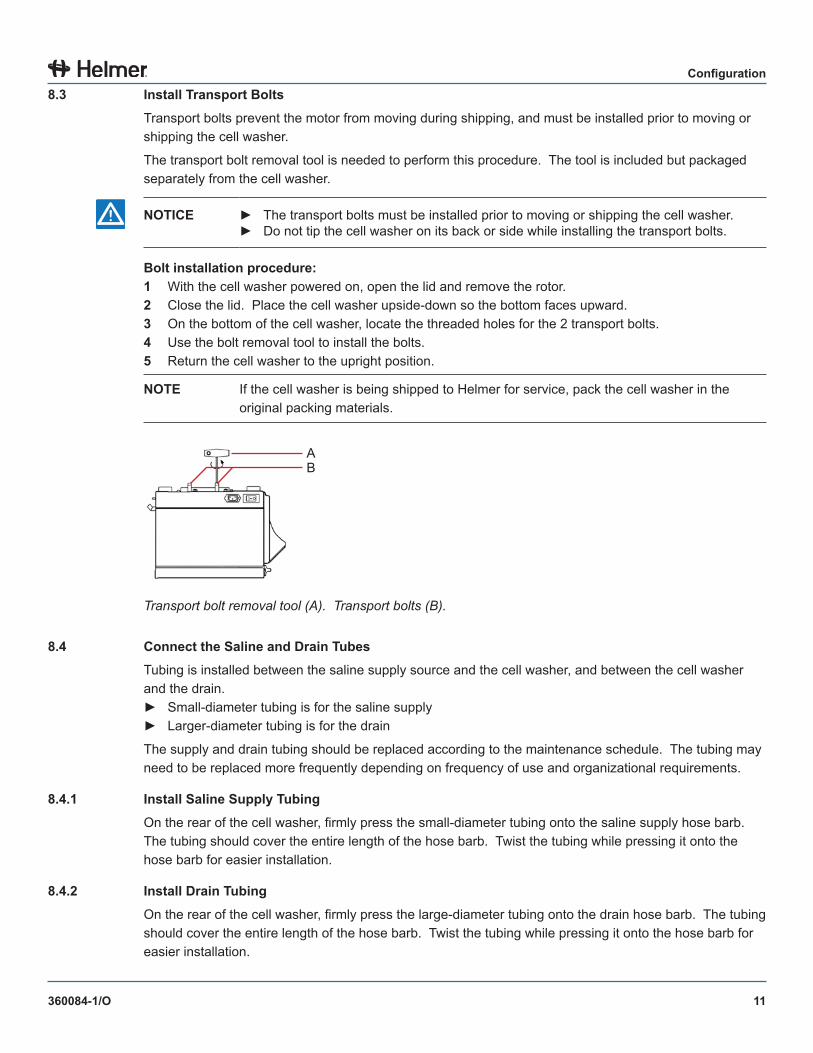
Bolt installation procedure:1 With the cell washer powered on, open the lid and remove the rotor.2 Close the lid. Place the cell washer upside-down so the bottom faces upward.3 On the bottom of the cell washer, locate the threaded holes for the 2 transport bolts.4 Use the bolt removal tool to install the bolts.5 Return the cell washer to the upright position.
NOTE If the cell washer is being shipped to Helmer for service, pack the cell washer in the original packing materials.
AB
Transport bolt removal tool (A). Transport bolts (B).
8 .4 Connect the Saline and Drain Tubes
Tubing is installed between the saline supply source and the cell washer, and between the cell washer and the drain.► Small-diameter tubing is for the saline supply► Larger-diameter tubing is for the drain
The supply and drain tubing should be replaced according to the maintenance schedule. The tubing may need to be replaced more frequently depending on frequency of use and organizational requirements.
8 .4 .1 Install Saline Supply Tubing
On the rear of the cell washer, firmly press the small-diameter tubing onto the saline supply hose barb. The tubing should cover the entire length of the hose barb. Twist the tubing while pressing it onto the hose barb for easier installation.
8 .4 .2 Install Drain Tubing
On the rear of the cell washer, firmly press the large-diameter tubing onto the drain hose barb. The tubing should cover the entire length of the hose barb. Twist the tubing while pressing it onto the hose barb for easier installation.
12
Configuration
360084-1/O
8 .4 .3 Connect the Cell Washer to the Saline Supply
If the fitting on the saline supply container is larger than the saline supply tubing, install an adapter between the saline supply container and the saline supply tubing. The adapter is included with the cell washer but is packaged separately.
Connect the adapter:1 Insert the small end of the adapter into the open end of the saline supply tubing.2 Connect the large end of the adapter to the connector on the saline supply container.
8 .4 .4 Connect the Cell Washer to the Drain
The cell washer has a gravity drain. Ensure the drain tubing flows downward, is as short as possible, and is not restricted.
WARNING Some saline solutions contain a sodium azide preservative which may react with the drain plumbing to form dangerous explosive azide salts. Check with the saline solution supplier before discharging waste solution directly into sanitary drains.
NOTICE ► Keep the drain line clean and free of restrictions to avoid liquid accumulation in the bowl. Accumulated liquid may enter the tubes during the wash process, yielding unacceptable results. Excessive liquid in the bowl may also enter the motor compartment, causing motor failure.
► Ensure the entire length of drain tubing is lower than the bottom of the bowl so that liquid does not accumulate in the bowl.
8 .4 .5 Remove Saline Supply Tubing or Drain Tubing
NOTICE If the cell washer has been run, the saline supply tubing will be under a vacuum. If the vacuum is not released, the saline supply hose barb may be damaged when the saline supply tubing is removed.
Twist the tubing from side to side while simultaneously pulling the tubing off of the hose barb.
8 .5 Initial Start Up1 Plug the power cord into a grounded outlet that meets the electrical requirements on the product
specification label.2 Switch the AC ON/OFF switch ON.
► The software version is displayed and all lamps are lit.► After approximately 8 seconds, the control panel displays one of the following:
► If the lid was open when the power was turned on, a summary of the washing parameters for the selected program is displayed and no lamps are lit.
► If the lid was closed when the power was turned on, “OPEN LID” is displayed and the Lid Ready lamp is lit.
13
Configuration
360084-1/O
8 .6 Open and Close the Lid
The cell washer is equipped with an electronic lock that prevents the lid from being opened during operation. The Lid Ready lamp must be lit before the lid can be opened.
NOTE ► If the lid is closed and there is no power to the cell washer, the lock will prevent the lid from being opened.
► If the lid must be opened when the cell washer is not powered on, or if the electronic lock is not working correctly, the lid can still be opened.
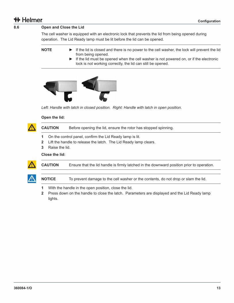
Left: Handle with latch in closed position. Right: Handle with latch in open position.
Open the lid:
CAUTION Before opening the lid, ensure the rotor has stopped spinning.
1 On the control panel, confirm the Lid Ready lamp is lit.2 Lift the handle to release the latch. The Lid Ready lamp clears.3 Raise the lid.
Close the lid:
CAUTION Ensure that the lid handle is firmly latched in the downward position prior to operation.
NOTICE To prevent damage to the cell washer or the contents, do not drop or slam the lid.
1 With the handle in the open position, close the lid.2 Press down on the handle to close the latch. Parameters are displayed and the Lid Ready lamp
lights.
14
Configuration
360084-1/O
8 .7 Release the Lid Lock
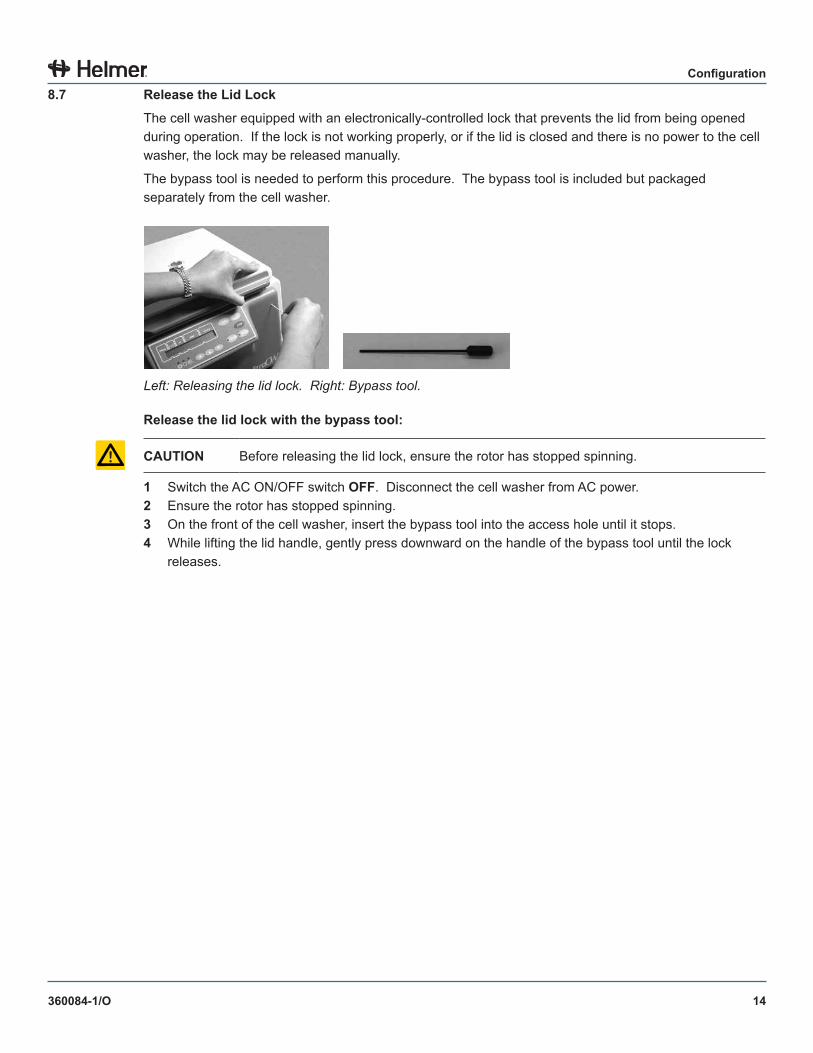
The cell washer equipped with an electronically-controlled lock that prevents the lid from being opened during operation. If the lock is not working properly, or if the lid is closed and there is no power to the cell washer, the lock may be released manually.
The bypass tool is needed to perform this procedure. The bypass tool is included but packaged separately from the cell washer.
Left: Releasing the lid lock. Right: Bypass tool.
Release the lid lock with the bypass tool:
CAUTION Before releasing the lid lock, ensure the rotor has stopped spinning.
1 Switch the AC ON/OFF switch OFF. Disconnect the cell washer from AC power.2 Ensure the rotor has stopped spinning.3 On the front of the cell washer, insert the bypass tool into the access hole until it stops.4 While lifting the lid handle, gently press downward on the handle of the bypass tool until the lock
releases.
15
Configuration
360084-1/O
9 Rotor InstallationEither a 12-place rotor or a 24-place rotor may be installed in the cell washer. Both rotors can hold either 10 mm x 75 mm tubes or 12 mm x 75 mm tubes.
9 .1 Install and Remove the Rotor
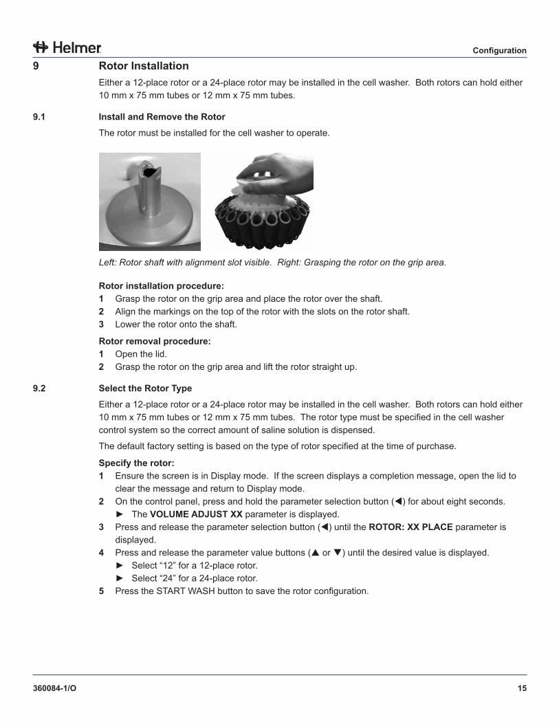
The rotor must be installed for the cell washer to operate.
Left: Rotor shaft with alignment slot visible. Right: Grasping the rotor on the grip area.
Rotor installation procedure:1 Grasp the rotor on the grip area and place the rotor over the shaft.2 Align the markings on the top of the rotor with the slots on the rotor shaft.3 Lower the rotor onto the shaft.
Rotor removal procedure:1 Open the lid.2 Grasp the rotor on the grip area and lift the rotor straight up.
9 .2 Select the Rotor Type
Either a 12-place rotor or a 24-place rotor may be installed in the cell washer. Both rotors can hold either 10 mm x 75 mm tubes or 12 mm x 75 mm tubes. The rotor type must be specified in the cell washer control system so the correct amount of saline solution is dispensed.
The default factory setting is based on the type of rotor specified at the time of purchase.
Specify the rotor:1 Ensure the screen is in Display mode. If the screen displays a completion message, open the lid to
clear the message and return to Display mode.2 On the control panel, press and hold the parameter selection button () for about eight seconds.
► The VOLUME ADJUST XX parameter is displayed.3 Press and release the parameter selection button () until the ROTOR: XX PLACE parameter is
displayed.4 Press and release the parameter value buttons ( or ) until the desired value is displayed.
► Select “12” for a 12-place rotor.► Select “24” for a 24-place rotor.
5 Press the START WASH button to save the rotor configuration.
16
Configuration
360084-1/O
9 .3 Balance the Rotor
The rotor must be balanced for the cell washer to operate correctly. If the rotor is not balanced, the process is stopped, “IMBALANCE” is displayed and the Imbalance lamp illuminates.
Tube holders and inserts must be installed correctly.
If the empty rotor passes the balancing operation but the screen displays an imbalance message during normal operation, the tubes may be loaded unevenly or maintenance has not been performed correctly or at the specified interval.
NOTE Refer to the service manual for cleaning instructions.
Rotor balancing procedure:1 Ensure all tubes have been removed from the tube holders.2 Install the rotor and close the lid.3 Change the Spin parameter values to perform the balance check.
a Ensure the screen is in Display mode. If the screen displays a completion message, open the lid to clear the message and return to Display mode.
b Press and release the parameter selection button () until each of the parameters in the following table are displayed.
Parameter ValueSpin(rpm) 3500Tspin(min) 0Tspin(sec) 20
d For each parameter, press and release the parameter value buttons ( or ) until the values in the table above are displayed.
4 Press the SPIN button to start the spin process.► If “OPEN LID” is displayed and the Lid Ready lamp is illuminated, the rotor is balanced.► If “IMBALANCE” is displayed and the Imbalance lamp is illuminated, the rotor is not balanced.
NOTE Refer to the service manual for additional instructions in balancing the rotor.
5 Reset the Spin parameters to their original values.
17
Configuration
360084-1/O
9 .4 Install and Remove Tube Holder Inserts
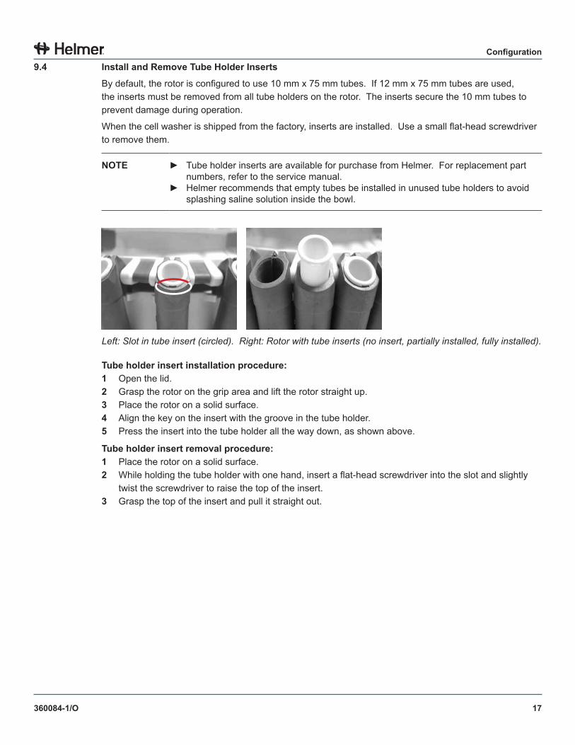
By default, the rotor is configured to use 10 mm x 75 mm tubes. If 12 mm x 75 mm tubes are used, the inserts must be removed from all tube holders on the rotor. The inserts secure the 10 mm tubes to prevent damage during operation.
When the cell washer is shipped from the factory, inserts are installed. Use a small flat-head screwdriver to remove them.
NOTE ► Tube holder inserts are available for purchase from Helmer. For replacement part numbers, refer to the service manual.
► Helmer recommends that empty tubes be installed in unused tube holders to avoid splashing saline solution inside the bowl.
Left: Slot in tube insert (circled). Right: Rotor with tube inserts (no insert, partially installed, fully installed).
Tube holder insert installation procedure:1 Open the lid.2 Grasp the rotor on the grip area and lift the rotor straight up.3 Place the rotor on a solid surface.4 Align the key on the insert with the groove in the tube holder.5 Press the insert into the tube holder all the way down, as shown above.
Tube holder insert removal procedure:1 Place the rotor on a solid surface.2 While holding the tube holder with one hand, insert a flat-head screwdriver into the slot and slightly
twist the screwdriver to raise the top of the insert.3 Grasp the top of the insert and pull it straight out.
18
Configuration
360084-1/O
9 .5 Load Tubes
NOTICE ► Using 10 mm x 75 mm tubes without the tube holder inserts could result in tube damage or rotor imbalance.
► The acceptable tube height is 75 mm ± 1.5 mm. Tubes that are out of tolerance may not move freely around the fill port and may be damaged.
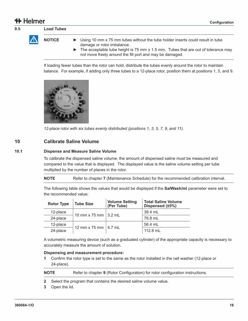
If loading fewer tubes than the rotor can hold, distribute the tubes evenly around the rotor to maintain balance. For example, if adding only three tubes to a 12-place rotor, position them at positions 1, 5, and 9.
12-place rotor with six tubes evenly distributed (positions 1, 3, 5, 7, 9, and 11).
10 Calibrate Saline Volume
10 .1 Dispense and Measure Saline Volume
To calibrate the dispensed saline volume, the amount of dispensed saline must be measured and compared to the value that is displayed. The displayed value is the saline volume setting per tube multiplied by the number of places in the rotor.
NOTE Refer to chapter 7 (Maintenance Schedule) for the recommended calibration interval.
The following table shows the values that would be displayed if the SalWash/ml parameter were set to the recommended value:
Rotor Type Tube Size Volume Setting (Per Tube)
Total Saline Volume Dispensed (±5%)
12-place10 mm x 75 mm 3.2 mL
38.4 mL24-place 76.8 mL12-place
12 mm x 75 mm 4.7 mL56.4 mL
24-place 112.8 mL
A volumetric measuring device (such as a graduated cylinder) of the appropriate capacity is necessary to accurately measure the amount of solution.
Dispensing and measurement procedure:1 Confirm the rotor type is set to the same as the rotor installed in the cell washer (12-place or
24-place).
NOTE Refer to chapter 9 (Rotor Configuration) for rotor configuration instructions.
2 Select the program that contains the desired saline volume value.3 Open the lid.
19
Configuration
360084-1/O
4 On the control panel, press and hold the SALINE button for about four seconds.► “CALIBRATE XXX.X ml” is displayed.► The cell washer is now in Calibration mode.► XXX.X represents the total saline volume that is dispensed.
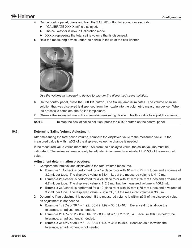
5 Hold the measuring device under the nozzle in the lid of the cell washer.
Use the volumetric measuring device to capture the dispensed saline solution.
6 On the control panel, press the CHECK button. The Saline lamp illuminates. The volume of saline solution that was displayed is dispensed from the nozzle into the volumetric measuring device. When the process is complete, the Saline lamp clears.
7 Observe the saline volume in the volumetric measuring device. Use this value to adjust the volume.
NOTE To stop the flow of saline solution, press the STOP button on the control panel.
10 .2 Determine Saline Volume Adjustment
After measuring the total saline volume, compare the displayed value to the measured value. If the measured value is within ±5% of the displayed value, no change is needed.
If the measured value varies more than ±5% from the displayed value, the saline volume must be calibrated. The saline volume can only be adjusted in increments equivalent to 0.5% of the measured value.
Adjustment determination procedure:1 Compare the total volume displayed to the total volume measured.
► Example 1: A check is performed for a 12-place rotor with 10 mm x 75 mm tubes and a volume of 3.2 mL per tube. The displayed value is 38.4 mL, but the measured volume is 41.0 mL.
► Example 2: A check is performed for a 24-place rotor with 12 mm x 75 mm tubes and a volume of 4.7 mL per tube. The displayed value is 112.8 mL, but the measured volume is 106.8 mL.
► Example 3: A check is performed for a 12-place rotor with 10 mm x 75 mm tubes and a volume of 3.2 mL per tube. The displayed value is 38.4 mL, but the measured volume is 38.6 mL.
2 Determine if an adjustment is needed. If the measured volume is within ±5% of the displayed value, an adjustment is not needed.► Example 1: ±5% of 38.4 = 1.92. 38.4 ± 1.92 = 36.5 to 40.4. Because 41.0 is above the
tolerance, an adjustment is needed.► Example 2: ±5% of 112.8 = 5.64. 112.8 ± 5.64 = 107.2 to 118.4. Because 106.8 is below the
tolerance, an adjustment is needed.► Example 3: ±5% of 38.4 = 1.92. 38.4 ± 1.92 = 36.5 to 40.4. Because 38.6 is within the
tolerance, an adjustment is not needed.
20
Configuration
360084-1/O
3 If an adjustment is needed, determine the difference in volume. Displayed - Measured = Difference
► Example 1: 38.4 - 41.0 = -2.6 mL► Example 2: 112.8 - 106.8 = 6.0 mL
4 Determine the adjustment value, rounded to the nearest whole number. Difference ÷ Measured × 200 = Adjustment Value
► Example 1: -2.6 ÷ 41.0 × 200 = -12.7 -13► Example 2: 6.0 ÷ 106.8 × 200 = 11.2 11
10 .3 Change the Saline Volume
After the saline adjustment volume has been determined, change the value of the VOLUME ADJUST XX global parameter by the determined amount.
EXAMPLE If the VOLUME ADJUST parameter was set to 10 and the adjustment value was determined to be -1, change the VOLUME ADJUST parameter to 9.
Volume change procedure:1 Ensure the screen is in Display mode. If the screen displays a completion message, open the lid to
clear the message and return to Display mode.2 On the control panel, press and hold the parameter selection button () for about eight seconds.
► The VOLUME ADJUST XX parameter is displayed.3 Press and release the parameter value buttons ( or ) until the desired value is displayed.4 Press the START WASH button to save the parameter setting.
21
Configuration
360084-1/O
11 Components
11 .1 Front, Lid, and Bowl
AB
CD
E
F
GHIJ
K
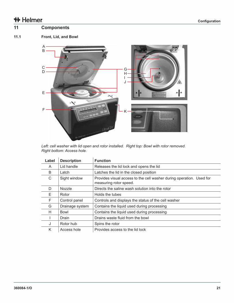
Left: cell washer with lid open and rotor installed. Right top: Bowl with rotor removed. Right bottom: Access hole.
Label Description FunctionA Lid handle Releases the lid lock and opens the lidB Latch Latches the lid in the closed positionC Sight window Provides visual access to the cell washer during operation. Used for
measuring rotor speed.D Nozzle Directs the saline wash solution into the rotorE Rotor Holds the tubesF Control panel Controls and displays the status of the cell washerG Drainage system Contains the liquid used during processingH Bowl Contains the liquid used during processingI Drain Drains waste fluid from the bowlJ Rotor hub Spins the rotorK Access hole Provides access to the lid lock
22
Configuration
360084-1/O
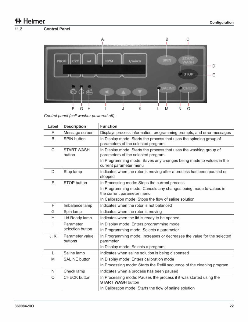
11 .2 Control Panel
A B C
F G H I J K L M N O
D
E
Control panel (cell washer powered off).
Label Description FunctionA Message screen Displays process information, programming prompts, and error messagesB SPIN button In Display mode: Starts the process that uses the spinning group of
parameters of the selected programC START WASH
buttonIn Display mode: Starts the process that uses the washing group of parameters of the selected programIn Programming mode: Saves any changes being made to values in the current parameter menu
D Stop lamp Indicates when the rotor is moving after a process has been paused or stopped
E STOP button In Processing mode: Stops the current processIn Programming mode: Cancels any changes being made to values in the current parameter menuIn Calibration mode: Stops the flow of saline solution
F Imbalance lamp Indicates when the rotor is not balancedG Spin lamp Indicates when the rotor is movingH Lid Ready lamp Indicates when the lid is ready to be openedI Parameter
selection button In Display mode: Enters programming modeIn Programming mode: Selects a parameter
J, K Parameter value buttons
In Programming mode: Increases or decreases the value for the selected parameter.In Display mode: Selects a program
L Saline lamp Indicates when saline solution is being dispensedM SALINE button In Display mode: Enters calibration mode
In Processing mode: Starts the Refill sequence of the cleaning programN Check lamp Indicates when a process has been pausedO CHECK button In Processing mode: Pauses the process if it was started using the
START WASH buttonIn Calibration mode: Starts the flow of saline solution

23
Configuration
360084-1/O
11 .3 Rotor
AB
C
D
E
F
G
H
Left: Top view of 12-place rotor with inserts installed. Right: Bottom view of 12-place rotor.
Label Description FunctionA Tube holder insert Holds 10 mm x 75 mm tubes in the tube holders. Removed when
using 12 mm x 75 mm tubes.B Optical reference Provides a reference for testing the rotor speedC Fill port Directs saline solution into the tubesD Alignment markings Provides a reference to align the rotor with the rotor shaftE Tube holder Holds the tube to be processedF Rotor lock Holds the tube holder during the decant step of the wash processG Clip Secures the tube holder to the ring on the rotorH Ring Holds the tube holders on the rotor
11 .4 Side
A B C D
Right side of cell washer.
Label Description FunctionA Fuse Prevents current overloadB Power switch Turns the cell washer on and offC Power connector Interface for the power cordD Product
specification labelProvides the model number, serial number, and electrical requirements for the cell washer
24
Configuration
360084-1/O
11 .5 Rear
A
B
C
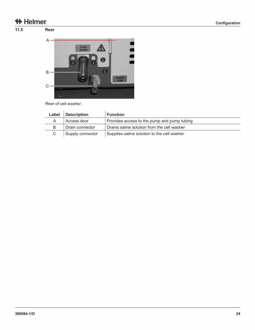
Rear of cell washer.
Label Description FunctionA Access door Provides access to the pump and pump tubingB Drain connector Drains saline solution from the cell washerC Supply connector Supplies saline solution to the cell washer
25
Programming
360084-1/O
Section III: ProgrammingThe cell washer can be programmed to execute a specific sequence of events, called a process. After the process has been programmed into the cell washer, the process can be initiated by the user. This section describes the types of processes (as part of a program) that the cell washer can execute. Each process is defined by process steps that are created and controlled by user-settable parameters. Parameters may be selected from two different menus, and may be customized.
The menus are:► Global menu► Program menu
NOTE ► Refer to chapter 15 (Sample Programs) for examples of processes and steps that may be programmed into the cell washer.
► Example programs are for information purposes only, and are not programmed into the cell washer as user-selectable programs.
12 Processes and Process StepsThe cell washer is capable of executing five types of processes. Each process consists of one or more process steps. Each process and process step can be customized by the user.
NOTE Refer to chapters 13 .2 (Global Parameters) and 13 .3 (Programs and Program Parameters) for customizing processes.
12 .1 Processes
The types of processes are as follows:
Washing► Includes at least one wash cycle► Includes steps: Fill, Spin, and Decant► May include steps: Agitation, Drop Spin-Down, Suspension, and/or Suspension-Agitation
Suspension► Includes one Suspension step► Excludes Fill, Spin, and Decant steps► May include a Suspension-Agitation step (after the Suspension step)
Spinning► Include one Spin step► Excludes Fill step► May include steps: Agitation and/or Decant
Agitation► Includes one Agitation step (and no other steps)
Cleaning► Cleaning process is a preset sequence that requires user intervention► After the user prepares the system for cleaning, the following steps are executed: Fill, Spin,
Decant, Agitation, Decant► The user must prepare the system for normal operation, initiating a Refill sequence to complete
the process
26
Programming
360084-1/O
12 .2 Process Steps
Each process consists of one or more process steps. Each process step is controlled with a combination of global parameters and program parameters.
NOTE Refer to chapter 13 (Programs and Parameters) for information regarding global parameters and program parameters.
12 .2 .1 Fill Step
During the Fill step, the tubes containing cells are filled with a specified amount of saline solution. As the rotor spins at 1100 RPM, saline is pumped from the reservoir through the flow meter to the saline dispensing nozzle. The nozzle directs the saline solution into the rotor, then the fill ports direct the saline solution into the tubes. Saline solution enters the tubes in a direct stream to maximize cell re-suspension.
In a washing process, the Fill step is always executed first (Fill, Spin, then Decant). Specify the amount of saline solution with the SalWash/ml parameter.
NOTE Refer to chapters 15 .1 (Sample Single-Cycle Washing Process) and 15 .2 (Sample Multiple-Cycle Washing Process) for sample processes that include a Fill step.
In a cleaning process, the Fill step is always executed first in the cycle (Fill, Spin, then Decant). The amount of saline solution is preset at 10 mL per tube. The fill volume exceeds the capacity of the tube to aid in flushing the drainage system.
12 .2 .2 Spin Step
During the Spin step, the rotor accelerates to the specified speed, spins for the specified time, then stops quickly. This step separates unwanted particles and creates a “button” of red blood cells at the bottom of each tube. The quick stopping prevents the re-suspension of the red blood cells and dislodging of the red blood cell button.
In a washing process, the Spin step is always executed second (Fill, Spin, then Decant). Specify the speed (RPM) with the Spin parameter, and the duration with the Twash(min) and Twash(sec) parameters.
NOTE Refer to chapters 15 .1 (Sample Single-Cycle Washing Process) and 15 .2 (Sample Multiple-Cycle Washing Process) for sample processes that include the Spin step.
In a spinning process, the Spin step is always executed first in the cycle, or immediately after the optional Agitation step. Specify the speed (RPM) with the Spin parameter, and the duration with the Tspin(min) and Tspin(sec) parameters.
NOTE Refer to chapters 15 .5 (Sample Spinning-Only Process); 15 .6 (Sample Spinning with Decanting Process); and 15 .7 (Sample Spinning After Agitation Process) for sample processes that include the Spin step.
In a cleaning process, the Spin step is always executed after the Fill step (Fill, Spin, then Decant). The speed is preset at 1500 RPM, and the duration is preset at 10 seconds.
27
Programming
360084-1/O
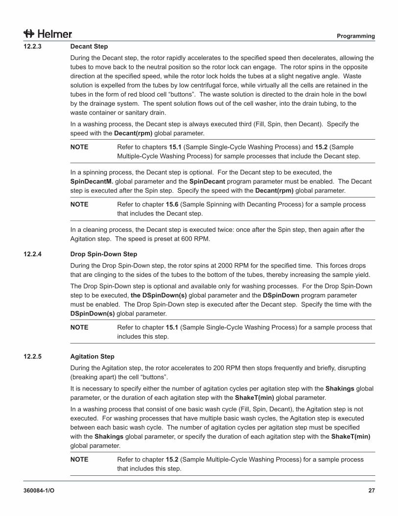
12 .2 .3 Decant Step
During the Decant step, the rotor rapidly accelerates to the specified speed then decelerates, allowing the tubes to move back to the neutral position so the rotor lock can engage. The rotor spins in the opposite direction at the specified speed, while the rotor lock holds the tubes at a slight negative angle. Waste solution is expelled from the tubes by low centrifugal force, while virtually all the cells are retained in the tubes in the form of red blood cell “buttons”. The waste solution is directed to the drain hole in the bowl by the drainage system. The spent solution flows out of the cell washer, into the drain tubing, to the waste container or sanitary drain.
In a washing process, the Decant step is always executed third (Fill, Spin, then Decant). Specify the speed with the Decant(rpm) global parameter.
NOTE Refer to chapters 15 .1 (Sample Single-Cycle Washing Process) and 15 .2 (Sample Multiple-Cycle Washing Process) for sample processes that include the Decant step.
In a spinning process, the Decant step is optional. For the Decant step to be executed, the SpinDecantM . global parameter and the SpinDecant program parameter must be enabled. The Decant step is executed after the Spin step. Specify the speed with the Decant(rpm) global parameter.
NOTE Refer to chapter 15 .6 (Sample Spinning with Decanting Process) for a sample process that includes the Decant step.
In a cleaning process, the Decant step is executed twice: once after the Spin step, then again after the Agitation step. The speed is preset at 600 RPM.
12 .2 .4 Drop Spin-Down Step
During the Drop Spin-Down step, the rotor spins at 2000 RPM for the specified time. This forces drops that are clinging to the sides of the tubes to the bottom of the tubes, thereby increasing the sample yield.
The Drop Spin-Down step is optional and available only for washing processes. For the Drop Spin-Down step to be executed, the DSpinDown(s) global parameter and the DSpinDown program parameter must be enabled. The Drop Spin-Down step is executed after the Decant step. Specify the time with the DSpinDown(s) global parameter.
NOTE Refer to chapter 15 .1 (Sample Single-Cycle Washing Process) for a sample process that includes this step.
12 .2 .5 Agitation Step
During the Agitation step, the rotor accelerates to 200 RPM then stops frequently and briefly, disrupting (breaking apart) the cell “buttons”.
It is necessary to specify either the number of agitation cycles per agitation step with the Shakings global parameter, or the duration of each agitation step with the ShakeT(min) global parameter.
In a washing process that consist of one basic wash cycle (Fill, Spin, Decant), the Agitation step is not executed. For washing processes that have multiple basic wash cycles, the Agitation step is executed between each basic wash cycle. The number of agitation cycles per agitation step must be specified with the Shakings global parameter, or specify the duration of each agitation step with the ShakeT(min) global parameter.
NOTE Refer to chapter 15 .2 (Sample Multiple-Cycle Washing Process) for a sample process that includes this step.
28
Programming
360084-1/O
In a spinning process, the Agitation step is optional. For the Agitation step to be executed, the AgitSpinM . global parameter and the Agit .Spin program parameter must be enabled. The Agitation step is executed before the Spin step. The number of agitation cycles per agitation step must be specified with the Shakings global parameter, or specify the duration of each agitation step with the ShakeT(min) global parameter.
NOTE Refer to chapter 15 .7 (Sample Spinning After Agitation Process) for a sample process that includes this step.
In an agitation process, the Agitation step must be executed. A series of global and program parameters must be set to certain values depending on how the process will be started.
NOTE Refer to chapter 15 .8 (Sample Agitation-Only Process) for sample agitation-only processes.
In a cleaning process, the Agitation step is always executed between the Decant steps. The number of agitation cycles is preset at 5.
12 .2 .6 Suspension Step
The Suspension step works the same as the Fill step, but is executed differently.
For the Suspension step to be executed, the SuspensionM . global parameter and the SalSusp/ml program parameter must be enabled. Specify the amount of saline solution that is dispensed with the SalSusp/ml program parameter.
In a washing process, the Suspension step is optional. If enabled, the Suspension step is executed after the final Decant step, preceded by the optional Drop Spin-Down step.
NOTE Refer to chapter 15 .1 (Sample Single-Cycle Washing Process) for a sample process that includes this step.
In a suspension process, the Suspension step must be executed. The Suspension step is either the first step or the only step.
NOTE Refer to chapters 15 .3 (Sample Suspension-Only Process) and 15 .4 (Sample Suspension with Agitation Process) for sample processes that include this step.
12 .2 .7 Suspension-Agitation Step
The Suspension-agitation step works the same as the Agitation step, but is executed differently.
For the Suspension-Agitation step to be executed, the Suspension step must first be executed, and both the Susp .Agit . global parameter and the SalSusp/ml program parameter must be enabled. The number of agitation cycles is controlled with the Susp .Agit . global parameter (set greater than 0).
In a washing process, the Suspension-Agitation step is optional. If enabled, the Suspension-Agitation step is executed after the Suspension step.
NOTE Refer to chapter 15 .1 (Sample Single-Cycle Washing Process) for a sample process that includes this step.
29
Programming
360084-1/O
In a suspension process, the Suspension-Agitation step is optional. If enabled, the Suspension-Agitation step is executed after the Suspension step.
NOTE Refer to chapter 15 .4 (Sample Suspension with Agitation Process) for a sample process that includes this step.
13 Programs and ParametersThe cell washer provides two types of parameters to control the cell washer. Global parameters control the overall functionality of the cell washer. Program parameters control the execution of programs used to carry out processes.
NOTE Verify the cell washer settings and change them accordingly before using the cell washer.
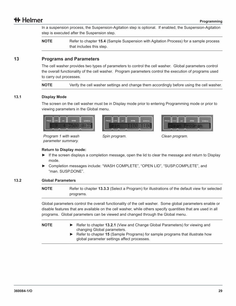
13 .1 Display Mode
The screen on the cell washer must be in Display mode prior to entering Programming mode or prior to viewing parameters in the Global menu.
Program 1 with wash parameter summary.
Spin program. Clean program.
Return to Display mode:► If the screen displays a completion message, open the lid to clear the message and return to Display
mode.► Completion messages include: “WASH COMPLETE”, “OPEN LID”, “SUSP.COMPLETE”, and
“man. SUSP.DONE”.
13 .2 Global Parameters
NOTE Refer to chapter 13 .3 .3 (Select a Program) for illustrations of the default view for selected programs.
Global parameters control the overall functionality of the cell washer. Some global parameters enable or disable features that are available on the cell washer, while others specify quantities that are used in all programs. Global parameters can be viewed and changed through the Global menu.
NOTE ► Refer to chapter 13 .2 .1 (View and Change Global Parameters) for viewing and changing Global parameters.
► Refer to chapter 15 (Sample Programs) for sample programs that illustrate how global parameter settings affect processes.
30
Programming
360084-1/O
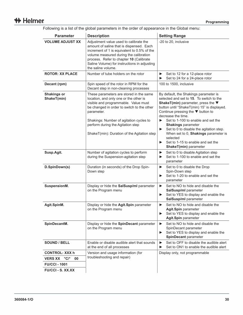
Following is a list of the global parameters in the order of appearance in the Global menu:
Parameter Description Setting RangeVOLUME ADJUST XX Adjustment value used to calibrate the
amount of saline that is dispensed. Each increment of 1 is equivalent to 0.5% of the volume measured during the calibration process. Refer to chapter 10 (Calibrate Saline Volume) for instructions in adjusting the saline volume.
-20 to 20, inclusive
ROTOR: XX PLACE Number of tube holders on the rotor ► Set to 12 for a 12-place rotor► Set to 24 for a 24-place rotor
Decant (rpm) Spin speed of the rotor in RPM for the Decant step in non-cleaning processes
100 to 1500, inclusive
Shakings or ShakeT(min)
These parameters are stored in the same location, and only one or the other is visible and programmable. Value must be changed in order to switch to the other parameter.
Shakings: Number of agitation cycles to perform during the Agitation step
ShakeT(min): Duration of the Agitation step
By default, the Shakings parameter is selected and set to 15. To switch to the ShakeT(min) parameter, press the button until “ShakeT(min) 15” is displayed. Continue pressing the button to decrease the time.► Set to 1-100 to enable and set the
Shakings parameter► Set to 0 to disable the agitation step.
When set to 0, Shakings parameter is selected
► Set to 1-15 to enable and set the ShakeT(min) parameter
Susp .Agit . Number of agitation cycles to perform during the Suspension-agitation step
► Set to 0 to disable Agitation step► Set to 1-100 to enable and set the
parameterD .SpinDown(s) Duration (in seconds) of the Drop Spin-
Down step► Set to 0 to disable the Drop
Spin-Down step► Set to 1-20 to enable and set the
parameterSuspensionM . Display or hide the SalSusp/ml parameter
on the Program menu► Set to NO to hide and disable the
SalSusp/ml parameter► Set to YES to display and enable the
SalSusp/ml parameterAgit .SpinM . Display or hide the Agit .Spin parameter
on the Program menu► Set to NO to hide and disable the
Agit .Spin parameter► Set to YES to display and enable the
Agit .Spin parameterSpinDecantM . Display or hide the SpinDecant parameter
on the Program menu► Set to NO to hide and disable the
SpinDecant parameter► Set to YES to display and enable the
SpinDecant parameterSOUND / BELL Enable or disable audible alert that sounds
at the end of all processes► Set to OFF to disable the audible alert► Set to ON1 to enable the audible alert
CONTROL: XXX h Version and usage information (for troubleshooting and repair)
Display only, not programmableVERS XX °C/* 00FU/CCI - 1001FU/CCI - S . XX .XX
31
Programming
360084-1/O
13 .2 .1 View and Change Global Parameters
View parameters:
NOTE While changing parameter values, if no button is pressed for approximately 16 seconds prior to saving, the screen returns to the Display mode for the selected program. Any changes are not saved.
1 Ensure the screen is in Display mode.► If the screen displays a completion message, open the lid to clear the message and return to
Display mode.2 On the control panel, enter Programming mode.
► Press and hold the parameter selection button () for about eight seconds.► The VOLUME ADJUST XX parameter is displayed.
3 Press and release the parameter selection button () until the desired parameter is displayed.
Change parameters:4 Press and release the parameter value buttons ( or ) until the desired value is displayed.5 Repeat steps 3 and 4 to change values for additional parameters (optional).6 Perform one of the following:
► To discard changes, press the STOP button or do not press any buttons for approximately 16 seconds. The screen returns to Display mode for the selected program.
► To save the changes, press the START WASH button. The screen displays “ ***ok*** ” to indicate the program was saved with the new values. The screen returns to Display mode for the selected program.
13 .3 Programs and Program Parameters
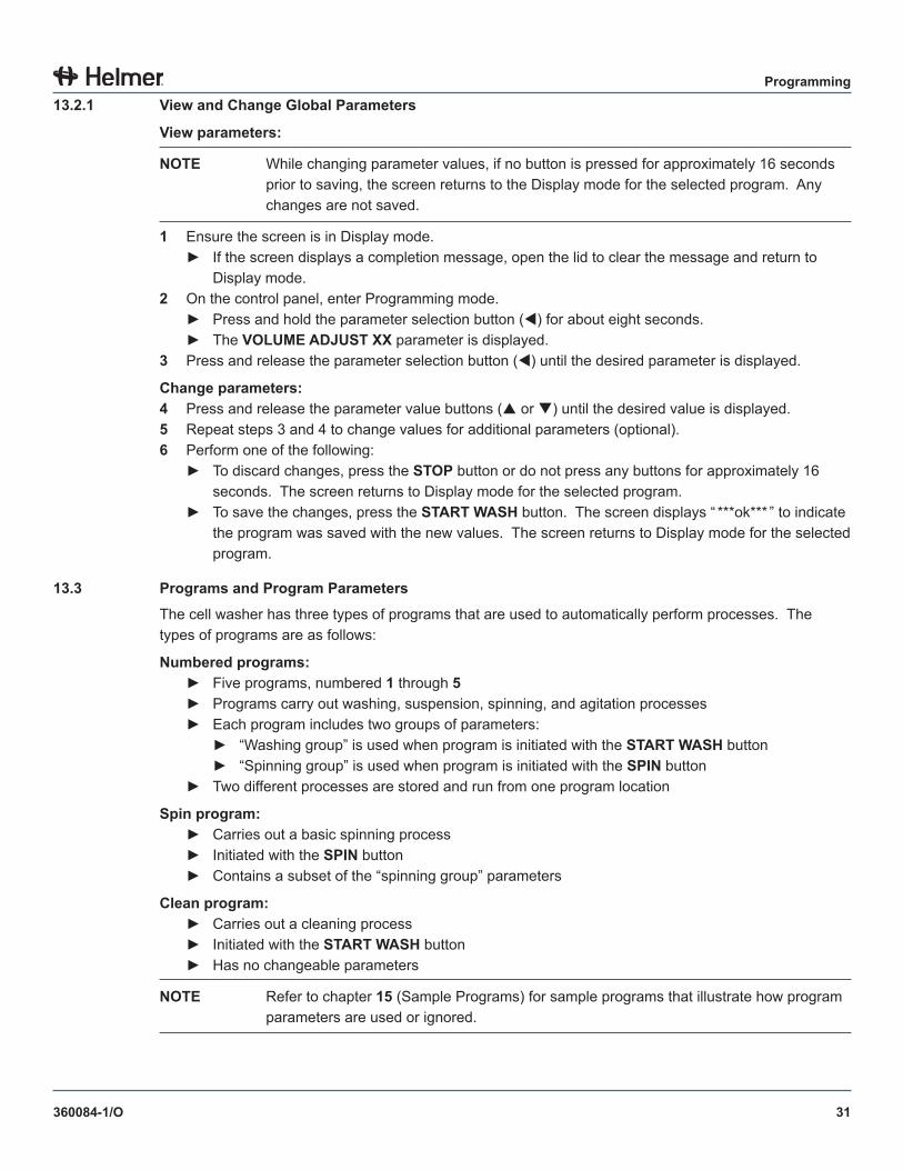
The cell washer has three types of programs that are used to automatically perform processes. The types of programs are as follows:
Numbered programs:► Five programs, numbered 1 through 5► Programs carry out washing, suspension, spinning, and agitation processes► Each program includes two groups of parameters:
► “Washing group” is used when program is initiated with the START WASH button► “Spinning group” is used when program is initiated with the SPIN button
► Two different processes are stored and run from one program location
Spin program:► Carries out a basic spinning process► Initiated with the SPIN button► Contains a subset of the “spinning group” parameters
Clean program:► Carries out a cleaning process► Initiated with the START WASH button► Has no changeable parameters
NOTE Refer to chapter 15 (Sample Programs) for sample programs that illustrate how program parameters are used or ignored.
32
Programming
360084-1/O
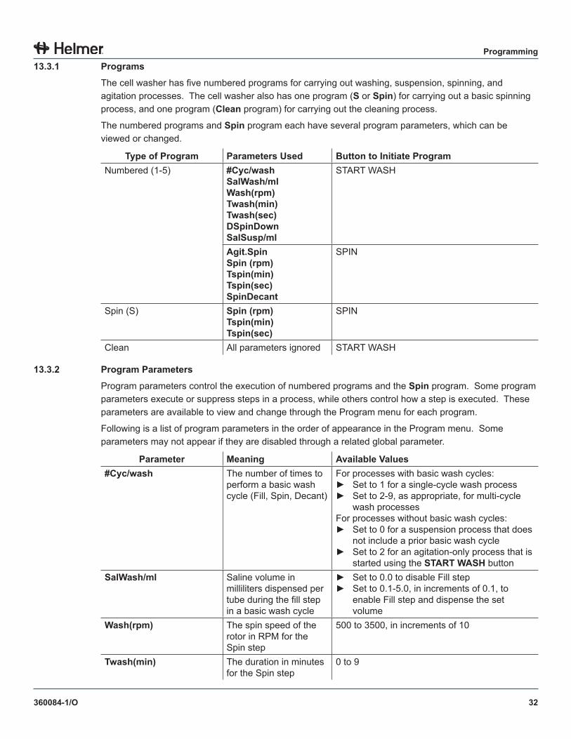
13 .3 .1 Programs
The cell washer has five numbered programs for carrying out washing, suspension, spinning, and agitation processes. The cell washer also has one program (S or Spin) for carrying out a basic spinning process, and one program (Clean program) for carrying out the cleaning process.
The numbered programs and Spin program each have several program parameters, which can be viewed or changed.
Type of Program Parameters Used Button to Initiate ProgramNumbered (1-5) #Cyc/wash
SalWash/mlWash(rpm)Twash(min)Twash(sec)DSpinDownSalSusp/ml
START WASH
Agit .SpinSpin (rpm)Tspin(min)Tspin(sec)SpinDecant
SPIN
Spin (S) Spin (rpm)Tspin(min)Tspin(sec)
SPIN
Clean All parameters ignored START WASH
13 .3 .2 Program Parameters
Program parameters control the execution of numbered programs and the Spin program. Some program parameters execute or suppress steps in a process, while others control how a step is executed. These parameters are available to view and change through the Program menu for each program.
Following is a list of program parameters in the order of appearance in the Program menu. Some parameters may not appear if they are disabled through a related global parameter.
Parameter Meaning Available Values#Cyc/wash The number of times to
perform a basic wash cycle (Fill, Spin, Decant)
For processes with basic wash cycles:► Set to 1 for a single-cycle wash process► Set to 2-9, as appropriate, for multi-cycle
wash processesFor processes without basic wash cycles:► Set to 0 for a suspension process that does
not include a prior basic wash cycle► Set to 2 for an agitation-only process that is
started using the START WASH buttonSalWash/ml Saline volume in
milliliters dispensed per tube during the fill step in a basic wash cycle
► Set to 0.0 to disable Fill step► Set to 0.1-5.0, in increments of 0.1, to
enable Fill step and dispense the set volume
Wash(rpm) The spin speed of the rotor in RPM for the Spin step
500 to 3500, in increments of 10
Twash(min) The duration in minutes for the Spin step
0 to 9
33
Programming
360084-1/O
Parameter Meaning Available ValuesTwash(sec) The duration in seconds
for the Spin step0 to 59
DSpinDown (Available only if the global parameter D .SpinDown(s) is enabled)
Specifies whether to include the Drop Spin-Down step
► Set to ON to include Drop Spin-Down step► Set to OFF to exclude Drop Spin-Down
stepSalSusp/ml (Available only if the global parameter SuspensionM . is enabled)
Saline volume in milliliters per tube for the Suspension step
► Set to 0.0 to disable Suspension step► Set to 0.1-5.0, in increments of 0.1, to
enable Suspension step and dispense the set volume
Agit .Spin (Available only if the global parameter AgitSpinM . is enabled)
Specifies whether to include an Agitation step before the Spin step
► Set to OFF to exclude Agitation step.► Set to ON to include Agitation step.
Spin(rpm) The spin speed of the rotor in RPM
500 to 3500, in increments of 10
Tspin(min) The duration in minutes for the Spin step
0 to 9
Tspin(sec) The duration in seconds for the Spin step
0 to 59
SpinDecant (Available only if the global parameter SpinDecantM . is enabled)
Specifies whether to include the Decant step
► Set to OFF to exclude Decant step► Set to ON to include Decant step
PROG The unique number for a program
► 1 to 5, for numbered programs► S for the Spin program► Clean Program for the cleaning program
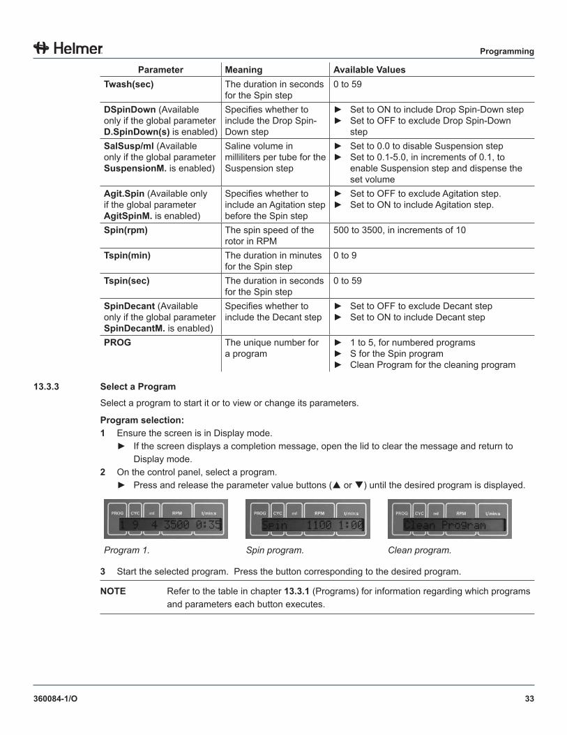
13 .3 .3 Select a Program
Select a program to start it or to view or change its parameters.
Program selection:1 Ensure the screen is in Display mode.
► If the screen displays a completion message, open the lid to clear the message and return to Display mode.
2 On the control panel, select a program.► Press and release the parameter value buttons ( or ) until the desired program is displayed.
Program 1. Spin program. Clean program.
3 Start the selected program. Press the button corresponding to the desired program.
NOTE Refer to the table in chapter 13 .3 .1 (Programs) for information regarding which programs and parameters each button executes.
34
Programming
360084-1/O
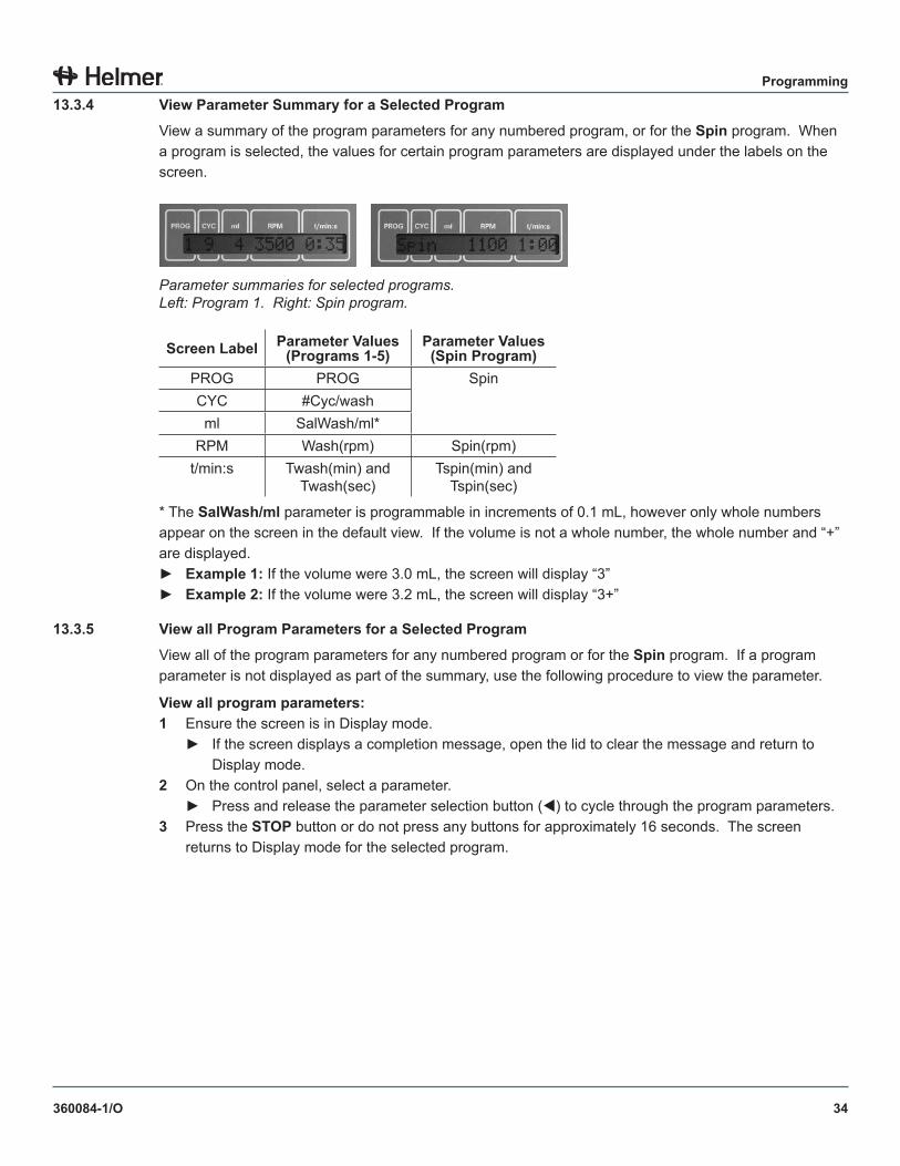
13 .3 .4 View Parameter Summary for a Selected Program
View a summary of the program parameters for any numbered program, or for the Spin program. When a program is selected, the values for certain program parameters are displayed under the labels on the screen.
Parameter summaries for selected programs. Left: Program 1. Right: Spin program.
Screen Label Parameter Values (Programs 1-5)
Parameter Values (Spin Program)
PROG PROG SpinCYC #Cyc/washml SalWash/ml*
RPM Wash(rpm) Spin(rpm)t/min:s Twash(min) and
Twash(sec)Tspin(min) and
Tspin(sec)
* The SalWash/ml parameter is programmable in increments of 0.1 mL, however only whole numbers appear on the screen in the default view. If the volume is not a whole number, the whole number and “+” are displayed.► Example 1: If the volume were 3.0 mL, the screen will display “3”► Example 2: If the volume were 3.2 mL, the screen will display “3+”
13 .3 .5 View all Program Parameters for a Selected Program
View all of the program parameters for any numbered program or for the Spin program. If a program parameter is not displayed as part of the summary, use the following procedure to view the parameter.
View all program parameters:1 Ensure the screen is in Display mode.
► If the screen displays a completion message, open the lid to clear the message and return to Display mode.
2 On the control panel, select a parameter.► Press and release the parameter selection button () to cycle through the program parameters.
3 Press the STOP button or do not press any buttons for approximately 16 seconds. The screen returns to Display mode for the selected program.
35
Programming
360084-1/O
13 .3 .6 Change Program Parameters
Change program parameters for any numbered program or the Spin program.
NOTE Refer to chapter 13 .3 (Programs and Program Parameters) for program parameter descriptions.
Change program parameter values:
NOTE While changing parameter values, if no button is pressed for approximately 16 seconds prior to saving, the screen returns to the Display mode for the selected program. Any changes are not saved.
1 Ensure the screen is in Display mode.► If the screen displays a completion message, open the lid to clear the message and return to
Display mode.2 On the control panel, select a parameter.
► Press and release the parameter selection button () until the desired parameter is displayed.3 Press and release the parameter value buttons ( or ) until the desired value is displayed.4 Repeat steps 2 and 3 to change values for additional parameters (optional).6 Perform one of the following:
► To discard changes, press the STOP button or do not press any buttons for approximately 16 seconds. The screen returns to Display mode for the selected program.
► To save the changes, press the START WASH button. The screen displays “ ***ok*** ” to indicate the program was saved with the new values. The screen returns to Display mode for the selected program.
36
Operation
360084-1/O
Section IV: Operation
14 Start and Stop Processes
CAUTION ► Push the lid/handle down until completely latched.► Do not attempt to open the lid during operation.
NOTE Verify the cell washer settings and change them accordingly before using the cell washer.
After processes have been programmed, a program may be started to automatically execute a process.
When a process is started, the cell washer enters Processing mode. In Processing mode, information about each step is displayed as the program progresses.
When the process is complete, a completion message is displayed. If the audible alert is enabled, the alert will also sound. The completion message remains on the screen and the audible alert repeats until the lid is opened. With some exceptions, the screen returns to Display mode for the selected program.
Processes may be stopped before the program has finished executing. Some processes may be paused and resumed. Pausing and resuming a process is useful if reagents must be added to the tubes at a particular point in the process.
NOTICE Do not operate the cell washer without a rotor in place.
14 .1 Start a Process
Processes are started either by pressing the START WASH button or the SPIN button.
For numbered programs, pressing the START WASH button starts a process that uses the “washing group” of parameters, while pressing the SPIN button starts processing using the “spinning group.” The Spin program is started only by pressing the SPIN button.
NOTE ► Refer to chapter 13 (Programs and Parameters) for more information about parameters used for each program type and start method.
► The Clean program requires additional tasks to be completed before starting. Refer to the service manual for instructions in starting the cleaning process using the Clean program.
Procedure:1 Confirm the saline volume has been calibrated.
NOTE Refer to chapter 10 (Calibrate Saline Volume) for instructions in calibrating the saline volume.
2 Install and load the rotor.3 Close the lid and ensure the Lid Ready lamp is lit.4 Select the program to execute.
NOTE Refer to chapter 13 .3 .3 (Select a Program) for information on available programs.
37
Operation
360084-1/O
5 Perform one of the following:► To start a process that uses the “washing group” of parameters for the selected program, press
the START WASH button.► To start a process that uses the “spinning group” of parameters for the selected program, press
the SPIN button.
14 .2 Stop a Process
When a process is stopped, the process is ended before the current step is completed. After the rotor has stopped spinning, a completion message is displayed. Opening the lid returns the cell washer to Display mode for the selected program.
Procedure:1 Press and hold the STOP button until the Stop lamp illuminates.
► When the rotor stops spinning, “OPEN LID” is displayed and the Lid Ready lamp illuminates.► If enabled, an audible alert sounds every 30 seconds until the lid is opened.
2 Open the lid.► The cell washer returns to Display mode for the selected program.
14 .3 Pause and Resume a Process
Pausing a process allows the tubes to be accessed during the process. The process may be resumed after the pause.
When a process is paused, the process stops after the current step is completed, at which time the lid may be opened. After the lid is closed, the process resumes where it left off.
Any multi-step process that is started with the START WASH button may be paused and resumed. If a process is paused, it cannot be stopped until it has been resumed.
Pause procedure:1 Press the CHECK button.
► The Check lamp illuminates.► After the current step is completed, the program is paused.► “OPEN LID” is displayed and the Lid Ready lamp illuminates.
2 Open the lid.► The Lid Ready lamp clears.► The Check lamp remains illuminated to indicate the process is paused.
Resume procedure:
1 Confirm the following:► The rotor is installed.► The lid is closed.► The program that is selected is the same one that was selected when the process was started.► The Lid Ready and Check lamps are lit.
2 On the control panel, press the START WASH button. The Check lamp clears and the process resumes.
38
Operation
360084-1/O
14 .4 Audible Alerts for Process Completion
When a wash or spin process is complete, an audible alert sounds. The alert may be enabled or disabled using the SOUND/BELL global parameter.
Change the alert:1 Ensure the screen is in Display mode. If the screen displays a completion message, open the lid to
clear the message and return to Display mode.2 On the control panel, press and hold the parameter selection button () for about eight seconds.
► The VOLUME ADJUST XX parameter is displayed.3 Press and release the parameter selection button () until the SOUND/BELL parameter is displayed.4 Press and release the parameter value buttons ( or ) until the desired value is displayed.
► Select “OFF” to disable the audible alert.► Select “ON1” to enable the alert.
NOTE Audible alerts also sound in the event of an error. Audible alerts for errors cannot be disabled. Refer to the service manual to diagnose errors.
15 Sample ProgramsThis section provides sample programs to further illustrate the effect of different settings on processes.
NOTE ► Refer to section III (Programming) for information and instructions about programming.► These programs are samples only. The cell washer has not been pre-programmed
with these settings.
39
Operation
360084-1/O
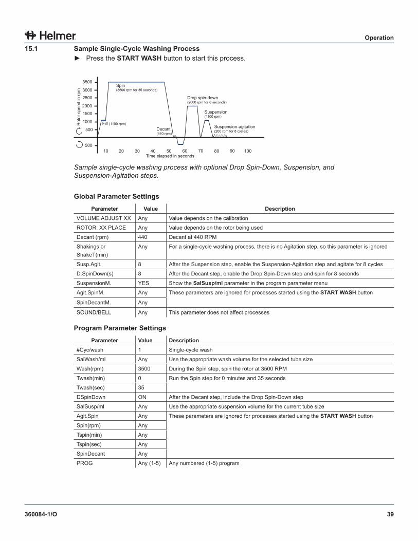
15 .1 Sample Single-Cycle Washing Process► Press the START WASH button to start this process.
500
1000
1500
2000
2500
3000
3500
50010 3020 40 50 60 70 1009080
Rot
or s
peed
in rp
m
Time elapsed in seconds
Fill (1100 rpm)
Spin(3500 rpm for 35 seconds)
Decant(440 rpm)
Drop spin-down(2000 rpm for 8 seconds)
Suspension (1100 rpm)
Suspension-agitation(200 rpm for 8 cycles)
Sample single-cycle washing process with optional Drop Spin-Down, Suspension, and Suspension-Agitation steps.
Global Parameter SettingsParameter Value Description
VOLUME ADJUST XX Any Value depends on the calibration
ROTOR: XX PLACE Any Value depends on the rotor being used
Decant (rpm) 440 Decant at 440 RPM
Shakings or ShakeT(min)
Any For a single-cycle washing process, there is no Agitation step, so this parameter is ignored
Susp.Agit. 8 After the Suspension step, enable the Suspension-Agitation step and agitate for 8 cycles
D.SpinDown(s) 8 After the Decant step, enable the Drop Spin-Down step and spin for 8 seconds
SuspensionM. YES Show the SalSusp/ml parameter in the program parameter menu
Agit.SpinM. Any These parameters are ignored for processes started using the START WASH button
SpinDecantM. Any
SOUND/BELL Any This parameter does not affect processes
Program Parameter SettingsParameter Value Description
#Cyc/wash 1 Single-cycle wash
SalWash/ml Any Use the appropriate wash volume for the selected tube size
Wash(rpm) 3500 During the Spin step, spin the rotor at 3500 RPM
Twash(min) 0 Run the Spin step for 0 minutes and 35 seconds
Twash(sec) 35
DSpinDown ON After the Decant step, include the Drop Spin-Down step
SalSusp/ml Any Use the appropriate suspension volume for the current tube size
Agit.Spin Any These parameters are ignored for processes started using the START WASH button
Spin(rpm) Any
Tspin(min) Any
Tspin(sec) Any
SpinDecant Any
PROG Any (1-5) Any numbered (1-5) program
40
Operation
360084-1/O
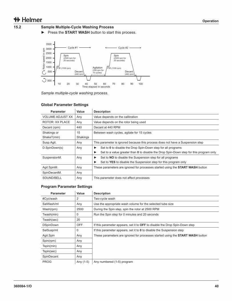
15 .2 Sample Multiple-Cycle Washing Process► Press the START WASH button to start this process.
500
1000
1500
2000
2500
3000
3500
50010 3020 40 50 60 70 1009080
Rot
or s
peed
in rp
m
Time elapsed in seconds
Fill (1100 rpm)
Spin (2500 rpm for 20 seconds)
Decant(440 rpm)
Agitation(200 rpm for 15 cycles)
Cycle #1
Fill (1100 rpm)
Spin (2500 rpm for 20 seconds)
Decant(440 rpm)
Cycle #2
Sample multiple-cycle washing process.
Global Parameter SettingsParameter Value Description
VOLUME ADJUST XX Any Value depends on the calibration
ROTOR: XX PLACE Any Value depends on the rotor being used
Decant (rpm) 440 Decant at 440 RPM
Shakings or ShakeT(min)
15 Shakings
Between wash cycles, agitate for 15 cycles
Susp.Agit. Any This parameter is ignored because this process does not have a Suspension step
D.SpinDown(s) Any ► Set to 0 to disable the Drop Spin-Down step for all programs► Set to a value greater than 0 to disable the Drop Spin-Down step for this program only
SuspensionM. Any ► Set to NO to disable the Suspension step for all programs► Set to YES to disable the Suspension step for this program only
Agit.SpinM. Any These parameters are ignored for processes started using the START WASH button
SpinDecantM. Any
SOUND/BELL Any This parameter does not affect processes
Program Parameter SettingsParameter Value Description
#Cyc/wash 2 Two-cycle wash
SalWash/ml Any Use the appropriate wash volume for the selected tube size
Wash(rpm) 2500 During the Spin step, spin the rotor at 2500 RPM
Twash(min) 0 Run the Spin step for 0 minutes and 20 seconds
Twash(sec) 20
DSpinDown OFF If this parameter appears, set it to OFF to disable the Drop Spin-Down step
SalSusp/ml 0 If this parameter appears, set it to 0 to disable the Suspension step
Agit.Spin Any These parameters are ignored for processes started using the START WASH button
Spin(rpm) Any
Tspin(min) Any
Tspin(sec) Any
SpinDecant Any
PROG Any (1-5) Any numbered (1-5) program
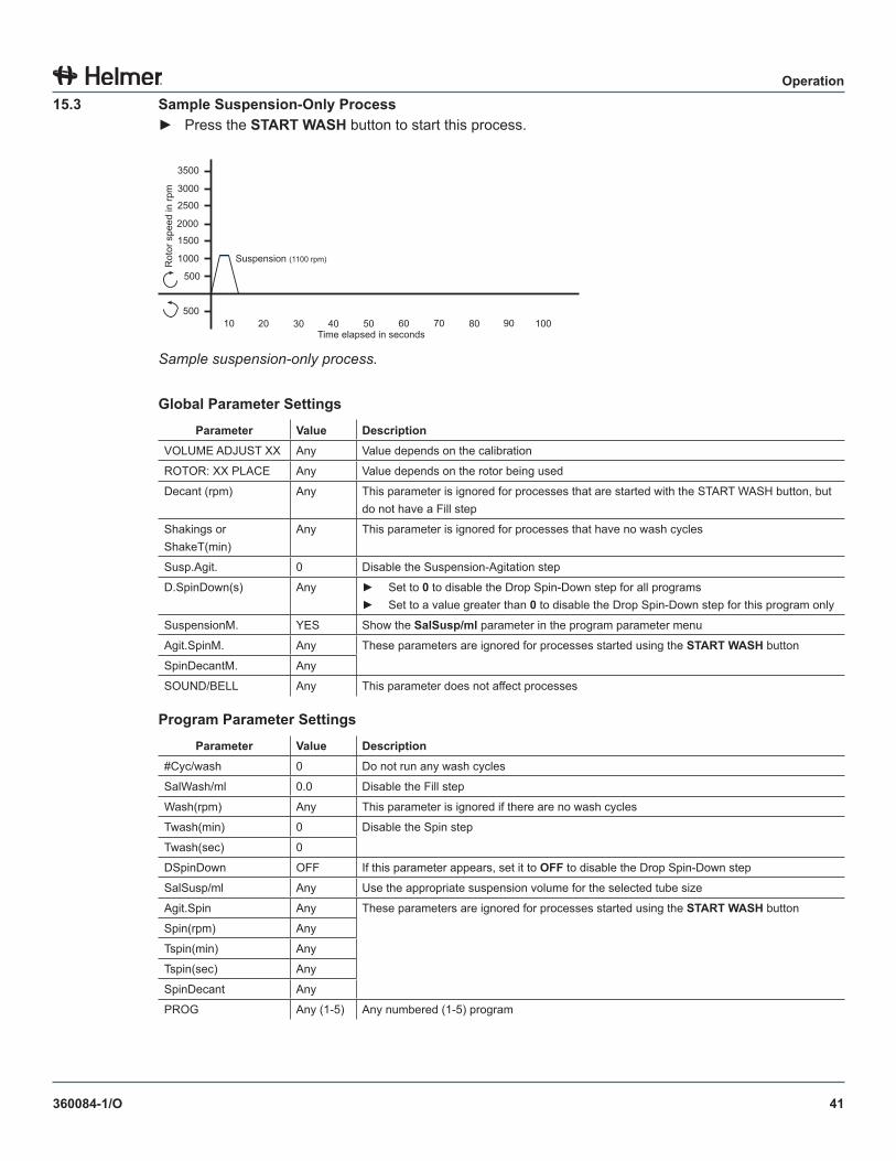
41
Operation
360084-1/O
15 .3 Sample Suspension-Only Process► Press the START WASH button to start this process.
500
1000
1500
2000
2500
3000
3500
50010 3020 40 50 60 70 1009080
Rot
or s
peed
in rp
m
Time elapsed in seconds
Suspension (1100 rpm)
Sample suspension-only process.
Global Parameter SettingsParameter Value Description
VOLUME ADJUST XX Any Value depends on the calibration
ROTOR: XX PLACE Any Value depends on the rotor being used
Decant (rpm) Any This parameter is ignored for processes that are started with the START WASH button, but do not have a Fill step
Shakings or ShakeT(min)
Any This parameter is ignored for processes that have no wash cycles
Susp.Agit. 0 Disable the Suspension-Agitation step
D.SpinDown(s) Any ► Set to 0 to disable the Drop Spin-Down step for all programs► Set to a value greater than 0 to disable the Drop Spin-Down step for this program only
SuspensionM. YES Show the SalSusp/ml parameter in the program parameter menu
Agit.SpinM. Any These parameters are ignored for processes started using the START WASH button
SpinDecantM. Any
SOUND/BELL Any This parameter does not affect processes
Program Parameter SettingsParameter Value Description
#Cyc/wash 0 Do not run any wash cycles
SalWash/ml 0.0 Disable the Fill step
Wash(rpm) Any This parameter is ignored if there are no wash cycles
Twash(min) 0 Disable the Spin step
Twash(sec) 0
DSpinDown OFF If this parameter appears, set it to OFF to disable the Drop Spin-Down step
SalSusp/ml Any Use the appropriate suspension volume for the selected tube size
Agit.Spin Any These parameters are ignored for processes started using the START WASH button
Spin(rpm) Any
Tspin(min) Any
Tspin(sec) Any
SpinDecant Any
PROG Any (1-5) Any numbered (1-5) program
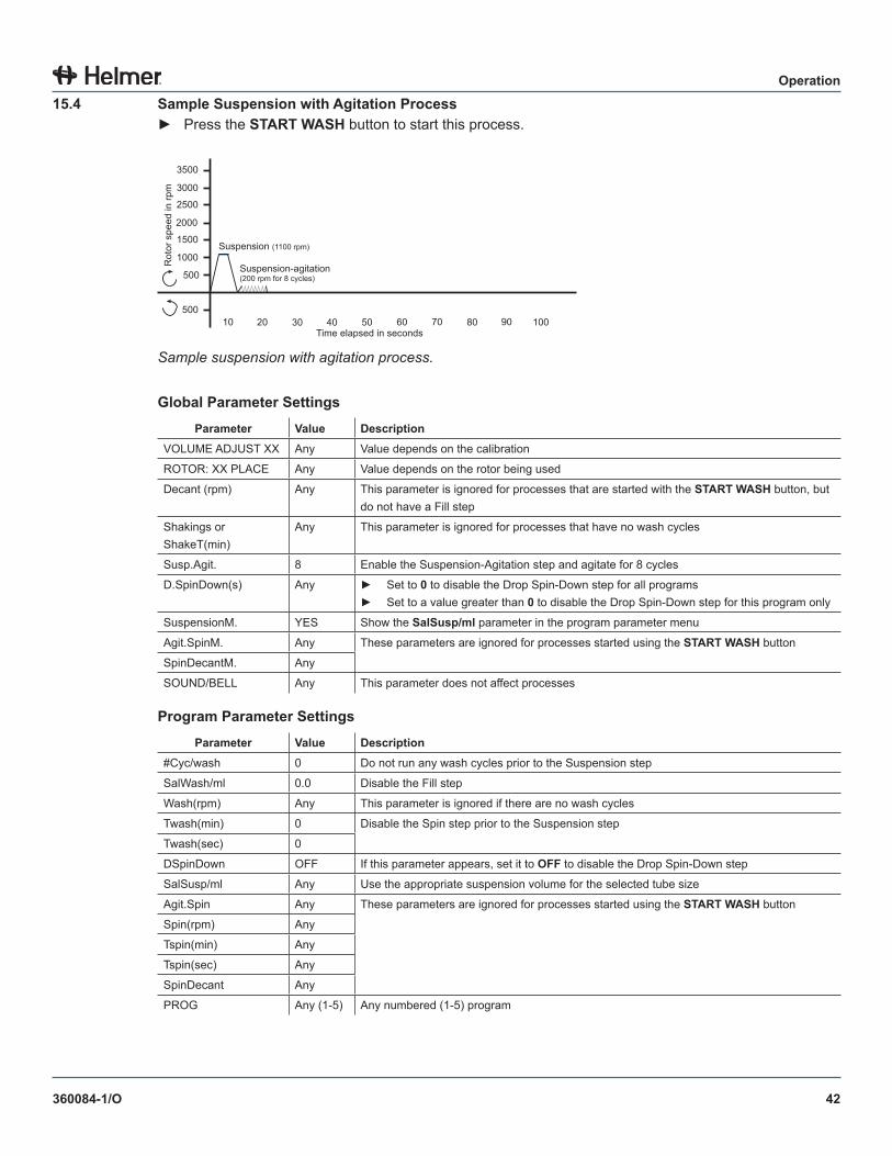
42
Operation
360084-1/O
15 .4 Sample Suspension with Agitation Process► Press the START WASH button to start this process.
500
1000
1500
2000
2500
3000
3500
50010 3020 40 50 60 70 1009080
Rot
or s
peed
in rp
m
Time elapsed in seconds
Suspension (1100 rpm)
Suspension-agitation(200 rpm for 8 cycles)
Sample suspension with agitation process.
Global Parameter SettingsParameter Value Description
VOLUME ADJUST XX Any Value depends on the calibration
ROTOR: XX PLACE Any Value depends on the rotor being used
Decant (rpm) Any This parameter is ignored for processes that are started with the START WASH button, but do not have a Fill step
Shakings or ShakeT(min)
Any This parameter is ignored for processes that have no wash cycles
Susp.Agit. 8 Enable the Suspension-Agitation step and agitate for 8 cycles
D.SpinDown(s) Any ► Set to 0 to disable the Drop Spin-Down step for all programs► Set to a value greater than 0 to disable the Drop Spin-Down step for this program only
SuspensionM. YES Show the SalSusp/ml parameter in the program parameter menu
Agit.SpinM. Any These parameters are ignored for processes started using the START WASH button
SpinDecantM. Any
SOUND/BELL Any This parameter does not affect processes
Program Parameter SettingsParameter Value Description
#Cyc/wash 0 Do not run any wash cycles prior to the Suspension step
SalWash/ml 0.0 Disable the Fill step
Wash(rpm) Any This parameter is ignored if there are no wash cycles
Twash(min) 0 Disable the Spin step prior to the Suspension step
Twash(sec) 0
DSpinDown OFF If this parameter appears, set it to OFF to disable the Drop Spin-Down step
SalSusp/ml Any Use the appropriate suspension volume for the selected tube size
Agit.Spin Any These parameters are ignored for processes started using the START WASH button
Spin(rpm) Any
Tspin(min) Any
Tspin(sec) Any
SpinDecant Any
PROG Any (1-5) Any numbered (1-5) program
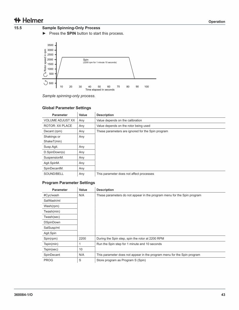
43
Operation
360084-1/O
15 .5 Sample Spinning-Only Process► Press the SPIN button to start this process.
500
1000
1500
2000
2500
3000
3500
500 10 30 20 40 50 60 70 100 90 80
Rot
or s
peed
in rp
m
Time elapsed in seconds
Spin (2200 rpm for 1 minute 10 seconds)
Sample spinning-only process.
Global Parameter SettingsParameter Value Description
VOLUME ADJUST XX Any Value depends on the calibration
ROTOR: XX PLACE Any Value depends on the rotor being used
Decant (rpm) Any These parameters are ignored for the Spin program
Shakings or ShakeT(min)
Any
Susp.Agit. Any
D.SpinDown(s) Any
SuspensionM. Any
Agit.SpinM. Any
SpinDecantM. Any
SOUND/BELL Any This parameter does not affect processes
Program Parameter SettingsParameter Value Description
#Cyc/wash N/A These parameters do not appear in the program menu for the Spin program
SalWash/ml
Wash(rpm)
Twash(min)
Twash(sec)
DSpinDown
SalSusp/ml
Agit.Spin
Spin(rpm) 2200 During the Spin step, spin the rotor at 2200 RPM
Tspin(min) 1 Run the Spin step for 1 minute and 10 seconds
Tspin(sec) 10
SpinDecant N/A This parameter does not appear in the program menu for the Spin program
PROG S Store program as Program S (Spin)
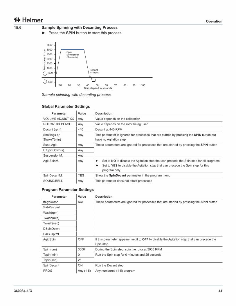
44
Operation
360084-1/O
15 .6 Sample Spinning with Decanting Process► Press the SPIN button to start this process.
500
1000
1500
2000
2500
3000
3500
50010 3020 40 50 60 70 1009080
Rot
or s
peed
in rp
m
Time elapsed in seconds
Spin (3000 rpm for 25 seconds)
Decant(440 rpm)
Sample spinning with decanting process.
Global Parameter SettingsParameter Value Description
VOLUME ADJUST XX Any Value depends on the calibration
ROTOR: XX PLACE Any Value depends on the rotor being used
Decant (rpm) 440 Decant at 440 RPM
Shakings or ShakeT(min)
Any This parameter is ignored for processes that are started by pressing the SPIN button but have no Agitation step
Susp.Agit. Any These parameters are ignored for processes that are started by pressing the SPIN button
D.SpinDown(s) Any
SuspensionM. Any
Agit.SpinM. Any ► Set to NO to disable the Agitation step that can precede the Spin step for all programs► Set to YES to disable the Agitation step that can precede the Spin step for this
program only
SpinDecantM. YES Show the SpinDecant parameter in the program menu
SOUND/BELL Any This parameter does not affect processes
Program Parameter SettingsParameter Value Description
#Cyc/wash N/A These parameters are ignored for processes that are started by pressing the SPIN button
SalWash/ml
Wash(rpm)
Twash(min)
Twash(sec)
DSpinDown
SalSusp/ml
Agit.Spin OFF If this parameter appears, set it to OFF to disable the Agitation step that can precede the Spin step
Spin(rpm) 3000 During the Spin step, spin the rotor at 3000 RPM
Tspin(min) 0 Run the Spin step for 0 minutes and 25 seconds
Tspin(sec) 25
SpinDecant ON Run the Decant step
PROG Any (1-5) Any numbered (1-5) program
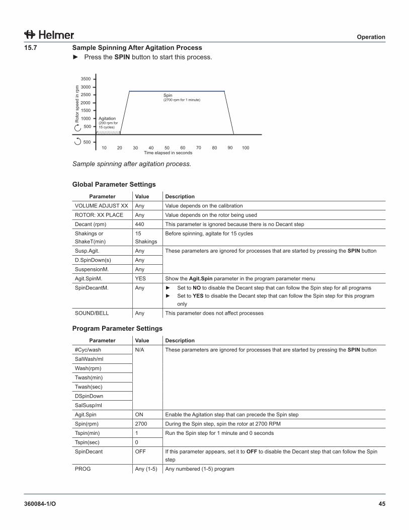
45
Operation
360084-1/O
15 .7 Sample Spinning After Agitation Process► Press the SPIN button to start this process.
500
1000
1500
2000
2500
3000
3500
50010 3020 40 50 60 70 1009080
Rot
or s
peed
in rp
m
Time elapsed in seconds
Spin (2700 rpm for 1 minute)
Agitation(200 rpm for 15 cycles)
Sample spinning after agitation process.
Global Parameter SettingsParameter Value Description
VOLUME ADJUST XX Any Value depends on the calibration
ROTOR: XX PLACE Any Value depends on the rotor being used
Decant (rpm) 440 This parameter is ignored because there is no Decant step
Shakings or ShakeT(min)
15 Shakings
Before spinning, agitate for 15 cycles
Susp.Agit. Any These parameters are ignored for processes that are started by pressing the SPIN button
D.SpinDown(s) Any
SuspensionM. Any
Agit.SpinM. YES Show the Agit .Spin parameter in the program parameter menu
SpinDecantM. Any ► Set to NO to disable the Decant step that can follow the Spin step for all programs► Set to YES to disable the Decant step that can follow the Spin step for this program
only
SOUND/BELL Any This parameter does not affect processes
Program Parameter SettingsParameter Value Description
#Cyc/wash N/A These parameters are ignored for processes that are started by pressing the SPIN button
SalWash/ml
Wash(rpm)
Twash(min)
Twash(sec)
DSpinDown
SalSusp/ml
Agit.Spin ON Enable the Agitation step that can precede the Spin step
Spin(rpm) 2700 During the Spin step, spin the rotor at 2700 RPM
Tspin(min) 1 Run the Spin step for 1 minute and 0 seconds
Tspin(sec) 0
SpinDecant OFF If this parameter appears, set it to OFF to disable the Decant step that can follow the Spin step
PROG Any (1-5) Any numbered (1-5) program
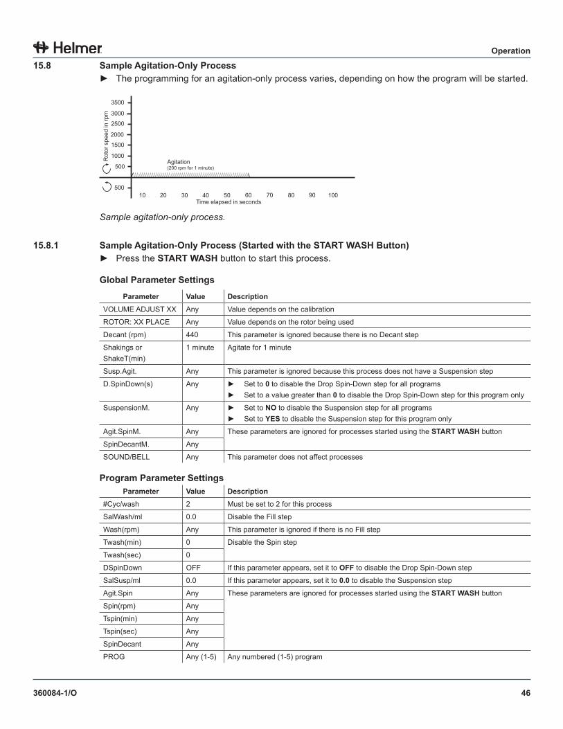
46
Operation
360084-1/O
15 .8 Sample Agitation-Only Process► The programming for an agitation-only process varies, depending on how the program will be started.
500
1000
1500
2000
2500
3000
3500
50010 3020 40 50 60 70 1009080
Rot
or s
peed
in rp
m
Time elapsed in seconds
Agitation(200 rpm for 1 minute)
Sample agitation-only process.
15 .8 .1 Sample Agitation-Only Process (Started with the START WASH Button)► Press the START WASH button to start this process.
Global Parameter SettingsParameter Value Description
VOLUME ADJUST XX Any Value depends on the calibration
ROTOR: XX PLACE Any Value depends on the rotor being used
Decant (rpm) 440 This parameter is ignored because there is no Decant step
Shakings or ShakeT(min)
1 minute Agitate for 1 minute
Susp.Agit. Any This parameter is ignored because this process does not have a Suspension step
D.SpinDown(s) Any ► Set to 0 to disable the Drop Spin-Down step for all programs► Set to a value greater than 0 to disable the Drop Spin-Down step for this program only
SuspensionM. Any ► Set to NO to disable the Suspension step for all programs► Set to YES to disable the Suspension step for this program only
Agit.SpinM. Any These parameters are ignored for processes started using the START WASH button
SpinDecantM. Any
SOUND/BELL Any This parameter does not affect processes
Program Parameter SettingsParameter Value Description
#Cyc/wash 2 Must be set to 2 for this process
SalWash/ml 0.0 Disable the Fill step
Wash(rpm) Any This parameter is ignored if there is no Fill step
Twash(min) 0 Disable the Spin step
Twash(sec) 0
DSpinDown OFF If this parameter appears, set it to OFF to disable the Drop Spin-Down step
SalSusp/ml 0.0 If this parameter appears, set it to 0 .0 to disable the Suspension step
Agit.Spin Any These parameters are ignored for processes started using the START WASH button
Spin(rpm) Any
Tspin(min) Any
Tspin(sec) Any
SpinDecant Any
PROG Any (1-5) Any numbered (1-5) program
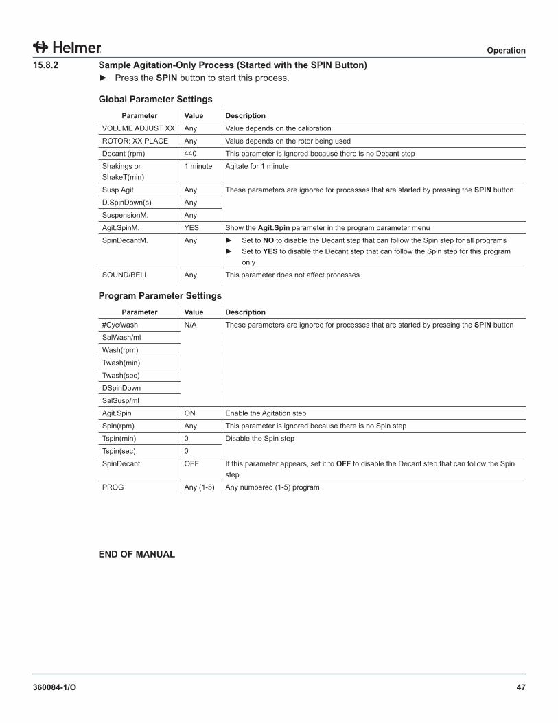
47
Operation
360084-1/O
15 .8 .2 Sample Agitation-Only Process (Started with the SPIN Button)► Press the SPIN button to start this process.
Global Parameter SettingsParameter Value Description
VOLUME ADJUST XX Any Value depends on the calibration
ROTOR: XX PLACE Any Value depends on the rotor being used
Decant (rpm) 440 This parameter is ignored because there is no Decant step
Shakings or ShakeT(min)
1 minute Agitate for 1 minute
Susp.Agit. Any These parameters are ignored for processes that are started by pressing the SPIN button
D.SpinDown(s) Any
SuspensionM. Any
Agit.SpinM. YES Show the Agit .Spin parameter in the program parameter menu
SpinDecantM. Any ► Set to NO to disable the Decant step that can follow the Spin step for all programs► Set to YES to disable the Decant step that can follow the Spin step for this program
only
SOUND/BELL Any This parameter does not affect processes
Program Parameter SettingsParameter Value Description
#Cyc/wash N/A These parameters are ignored for processes that are started by pressing the SPIN button
SalWash/ml
Wash(rpm)
Twash(min)
Twash(sec)
DSpinDown
SalSusp/ml
Agit.Spin ON Enable the Agitation step
Spin(rpm) Any This parameter is ignored because there is no Spin step
Tspin(min) 0 Disable the Spin step
Tspin(sec) 0
SpinDecant OFF If this parameter appears, set it to OFF to disable the Decant step that can follow the Spin step
PROG Any (1-5) Any numbered (1-5) program
END OF MANUAL


HELMER SCIENTIFIC14400 Bergen BoulevardNoblesville, IN 46060 USA
PH +1.317.773.9073FAX +1.317.773.9082www.helmerinc.com