Ultra High Temperature Ceramics all depends…. UHTCs
65
Properties: It all depends…. Materials Properties: It all depends…. Properties: It all depends…. all depends…. Sylvia M. Johnson NASA-Ames Research Center TPS TIM Langley Research Center September 29-30, 2015 Ultra High Temperature Ceramics UHTCs
Transcript of Ultra High Temperature Ceramics all depends…. UHTCs

Properties: It all depends….Materials Properties: It all depends….
Properties: It all depends….
all depends….
Sylvia M. Johnson
NASA-Ames Research Center
TPS TIM
Langley Research Center
September 29-30, 2015
Ultra High Temperature CeramicsUHTCs

Outline
• What are UHTCs?• Some early history and rationale• History of development at Ames
June 2015 2

3
What are UHTCs?
ZrB2 HfB2
From American Ceramic Society Phase Diagrams
Diborides have very high melting temperatures and high thermal conductivity
UHTCs include carbides and borides of transitional metals, e.g. Zr, Hf, Ta

Some UHTC Development History
4
• HfB2 and ZrB2 materials investigated in early 1950s as nuclear reactor material
• Extensive work in 1960s & 1970s (by ManLabs for Air Force) showed potential for HfB2 and ZrB2 for use as nosecones and leading edge materials (Clougherty, Kaufman, Kalish, Hill, Peters, Rhodes et al.)
• Gap in sustained development during 1980s and most of 1990s
- AFRL considered UHTCs for long-life, man-rated turbine engines
• During late 1990s, NASA Ames revived interest in HfB2/SiC, ZrB2/SiC ceramics for sharp leading edges
• Ballistic flight experiments: Ames teamed with Sandia National Laboratories New Mexico, Air Force Space Command, and TRW
- SHARP*-B1 (1997) UHTC nosetip & SHARP-B2 (2000) UHTC strake assembly
• Space Launch Initiative (SLI , NGLT, UEET programs: 2001-5
• NASA’s Fundamental Aeronautics Program funded research until 2009
• Substantial current ongoing effort at universities, government agencies, & international laboratories
* Slender Hypervelocity Aerothermodynamic Research Probes

UHTC Suitability for TPS
5
• UHTCs are only for specialized TPS applications for which other material systems are not as capable or straightforward or their capabilities are required when active cooling is not feasible.
• Choice of materials driven by design, environment, and material properties.- Feasible simple nose-cone and passive-leading-edge designs have been
developed. (UHTC leading edge designs use small volumes of material.)- UHTCs have high temperature capabilities (> 2000 °C / 3600 °F)
• Material selection should be based on appropriate testing of matured material in relevant environment.
• Concerns about monolithic UHTC properties are being addressed by processing and engineering improvements (ceramic matrix composites [CMCs])
• Use will depend upon level of maturity relevant to specific application

6
Sharp Leading Edge TechnologyBenefits of sharp leading edge technology.
- Enhanced vehicle performance- Leads to improvements in safety Increased vehicle cross range Greater launch window with safe abort to ground
Sharp leading edges place significantly higher temperature requirements on the materials:- Current shuttle reinforced carbon-carbon (RCC) leading edge materials:
T~1650°C- Sharp leading edged vehicles will require: T>2000°C
Ultra High Temperature Ceramic compositions are one candidate for use in sharp leading edge applications.

Sharp Leading Edge Energy Balance
7
Insulators and UHTCs manage energy in different ways:• Insulators store energy until it can be eliminated in the same way as it
entered• UHTCs conduct energy through the material and reradiate it through
cooler surfaces
Dean Kontinos, Ken Gee and Dinesh Prabhu. “Temperature Constraints at the Sharp Leading Edge of a Crew Transfer Vehicle.” AIAA 2001-2886 35th AIAA Thermophysics Conference, 11-14 June 2001, Anaheim CA
Sharp Nose
UHTC
High Thermal Conductivity
Sharp Nose
Leading Edges
8
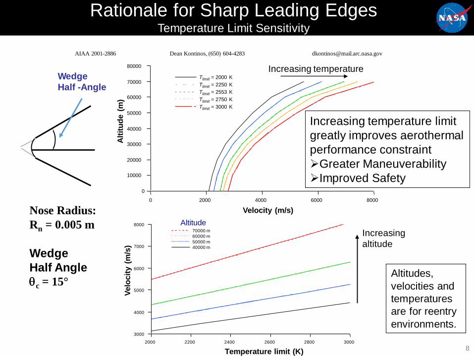
Rationale for Sharp Leading EdgesTemperature Limit Sensitivity
Nose Radius:Rn = 0.005 m
Wedge Half Angleθc = 15°
80000
70000
60000
50000
40000
30000
20000
10000
0
Altit
ude
(m)
80006000400020000
Velocity (m/s)
Tlimit = 2000 KTlimit = 2250 KTlimit = 2553 KTlimit = 2750 KTlimit = 3000 K
8000
7000
6000
5000
4000
3000
Velo
city
(m/s
)
300028002600240022002000
Temperature limit (K)
70000 m60000 m50000 m40000 m
Increasing temperature limit greatly improves aerothermal performance constraintGreater ManeuverabilityImproved Safety
AIAA 2001-2886 Dean Kontinos, (650) 604-4283 [email protected]
WedgeHalf -Angle
Increasing temperature
Altitude
Altitudes, velocities and temperatures are for reentry environments.
Increasing altitude

9
Potential Benefit – Impact On Crew Safety
Blunt Body min. time C. Verde = 390 secSHARP-V5 min. time C. Verde = 279 secSHARP-V5 max. time San Juan = 280 secSHARP-V5 min. time San Juan = 218 sec
Results of the SHARP CTV study show the potential of minimizing the need to abort into the ocean by increasing the capability of landing on a runway in the event of a failure during launch. 390 - 218 = 172 seconds improvement.
28 deg. Inclination

10
ISS Ground Track vs. Cross Range
International Space StationGround Track
Blunt Range Max Cross-Range 1360 nautical miles
Sharp Body Max Cross-Range3500 nautical miles
ISS GroundTrack

11
Sharp Nose
Surface Energy Balance
AIAA 2001-2886 “Temperature Constraints at the Sharp Leading Edge of a Crew Transfer Vehicle” Dean Kontino, Ken Gee and Dinesh Prabhu35th AIAA Thermophysics Conference, 11-14 June 2001, Anaheim CA. Dean Kontinos, (650) 604-4283 [email protected]
Blunt Nose
SiC Coated C/CUHTC
• Insulators and UHTCs manage energy in different ways:• Insulators store energy until it can be eliminated the same way it came in• UHTCs conduct energy through the material and reradiate it through cooler surfaces
Low ThermalConductivity
High Thermal Conductivity
qcond ≈ 0

Aerospace Application
• Some can beused as a monolith or matrix;some are more appropriate as a coating.
• Thermal properties have a significant impact on the surface temperatures.
UHTC billets, quarter for scale
• The diborides of hafnium and zirconium are of particular interest to the aerospace industry for sharp leading edge applications which require chemical and structural stability at extremely high operating temperatures.

Blunt LE,
Materials for Sharp Leading Edges
High Temperature at Tip
Steep Temperature Gradient
Teledyne Scientific
Sustained Hypersonic Flight Limited by Materials• High heat flux over small area• High temperature, oxidation, erosion• Very high temperature gradients
UHTCs (ZrB2/HfB2-based composites)• High temperature capability and high
thermal conductivity• Poor oxidation resistance Modeling/Validation• Low fracture toughness Fiber Reinforcement
~2000C
Cowl Leading Edge
Free-Stream at Mach 813
Courtesy: AFRL
From D. Glass, NASA

14
Interest in UHTCs for Aerospace Applications Initiated Over Thirty Years Ago
• Initial work performed by ManLabs Inc. in the 1960’s and 1970’s for the Air Force on materials capable of withstanding extreme temperatures
• In the early 1990’s NASA-Ames began investigating HfB2 and ZrB2based materials for sharp leading edge applications.- Ground based research: initial materials development by external
vendors, Arc Jet testing, computer modeling, etc.- SHARP-B1(1997) and SHARP-B2 (2000) ballistic flight experiments
• NASA-Ames was mostly interested in HfB2-SiC composites- For a monolithic ceramic HfB2-SiC has a relatively good thermal shock
resistance- Retains shape at elevated temperatures

Processing of HfB2-SiC
15
• HfB2 has a narrow range ofstoichiometry with a meltingtemperature of 3380°C
Density = 11.2 g/cm3
• Silicon carbide is added toboride powders
- Promotes refinement of microstructure
- Decreases thermal conductivityof HfB2
- 20v% may not be optimal but iscommon amount added
- SiC will oxidize either passivelyor actively, depending upon theenvironment
Density = 3.2 g/cm3
HfB2
Phase diagram from American Ceramic Society Phase diagrams

16
HfB2/SiC Materials Have Relatively High Thermal Conductivities
• HfB2/SiC material was measured from 1999 era materials manufacturedby an outside vendor.• Thermal Diffusivity and Heat Capacityof HfB2/SiC was measured using Laser Flash.

UHTC Material Properties
17
Source: ManLabs and Southern Research Institute
* Flexural Strength# R. P. Tye and E. V. Clougherty, “The Thermal and Electrical Conductivities of Some Electrically Conducting Compounds.” Proceedings of the Fifth Symposium on Thermophysical Properties, The American Society of Mechanical Engineers, Sept 30 – Oct 2 1970. Editor C. F. Bonilla, pp 396-401.
Sharp leading edges require :• High thermal conductivity (directional)• High fracture toughness/mechanical strength/hardness• Oxidation resistance (in reentry conditions)

UHTC Flight Experiments
September 30, 201518
• 2 flight experiments on U.S. Air Force Minuteman III missile carrying a modified Mk 12A reentry vehicle (RV)• SHARP B1: 1997• SHARP B2: 2000
• Purpose was to test materials• Materials were made by 2 different outside vendors• Materials were not recovered in SHARP B1
• Sharp nosetip on RV • Materials were recovered from SHARP B2
• 4 strakes on body of RV• 3 different materials: HfB2/SiC, ZrB2/SiC, ZrB2/SiC/C• One pair retracted before ablation predicted• One pair retracted after ablation predicted

Flight Hardware
SHARP-B1 May 21, 1997 SHARP-B2 Sept. 28, 2000

20
SHARP-B2
• Flight test designed to evaluate three different compositions of UHTCs in strake (fin) configuration exposed to ballistic reentry environment.
• Strakes exposed as vehicle reentered atmosphere and then retracted into protective housing.
• Material recovered. Led to new effort in UHTCs / decision to bring development in-house and improve processing.

21
• Post-flight recovery showed that all four HfB2-SiC aft-strake segments suffered similar, multiple fractures.
• No evidence of severe heating damage (for example, ablation, spallation, or burning) was observed.
• Defects inherent in material lot are present on fracture surfaces.
• Actual material properties exhibit wider scatter and greater temperature dependence than those assumed in design.
Pair 1 (47.9 km) Pair 2 (43.3 km)
Recovered Strakes

22
HfB2 agglomerate
SiC agglomerate
Processing Defects on Fracture Surface of Aft-Segment, Strake 2
200 µm
50.0 µm

23
Processing Defects in HfB2-SiCFlexure Specimens
HfB2 agglomerate
Grafoil™ agglomerate
100 µm
20 µm

A Cautionary Tale
• Materials did not have expected fracture toughness, strength, or reliability (Weibull modulus).
• Unexpected fractures were due to poor materials processing by external vendor.
• SHARP B-2 underlined importance of controlling materials development, processing methodologies, and resulting material properties if we are to get the maximum value from an experiment.
24
Poorly processed HfB220v%SiC
100 µm
Large HfB2 agglomerate Large SiC-rich agglomerate

25
Typical Microstructures of Previous HfB2 - 20% SiC Materials
1970’s Era SHARP-B1Circa 1997
SHARP-B2Circa 1999
HfB2: ρ = 11.2 g/ccSiC: ρ = 3.2 g/cc
Coarse, poorly sintered microstructures and/or large agglomerates of SiC and HfB2were common in previous materials.
• Improved processing techniques are required to produce homogeneous, fine grained materials

26
Motivation for In-House UHTC Processing at Ames
• Until 2000 there was no consistent effort to develop the UHTC family of materials at NASA.- Development work was primarily part of flight experiment programs such as the
SHARP-B1 and SHARP-B2 flight experiments• Different vendors supplied materials for the SHARP-B1 and SHARP-B2
flight experiments.- NASA did not retain the knowledge on how to process these materials.
Therefore, each time we have had to start at the beginning, evaluating material properties, etc…
• Resulted in inconsistent materials- Significant differences in microstructure leads to significant variability in
material properties.• Bringing the UHTC processing in-house allowed the government to
retain the knowledge of how to process the materials and then transfer the technology to industry for production.- Precedent was set at ARC with development of tile coatings.
27
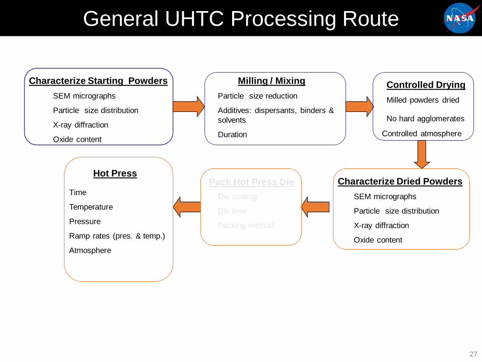
General UHTC Processing Route
Characterize Starting PowdersSEM micrographs
Particle size distribution
X-ray diffraction
Oxide content
Milling / MixingParticle size reduction
Additives: dispersants, binders & solvents
Duration
Controlled DryingMilled powders dried
No hard agglomerates
Characterize Dried PowdersSEM micrographs
Particle size distribution
X-ray diffraction
Oxide content
Hot Press
Time
Temperature
Pressure
Ramp rates (pres. & temp.)
Atmosphere
Pack Hot Press DieDie coating
Die liner
Packing method
Controlled atmosphere

28
Powder Granulation
• Large density difference between HfB2 (ρ = 11.2 g/cc) and SiC (ρ = 3.2 g/cc) make these constituents susceptible to phase segregation
• Powders are granulated by freeze-drying to prevent phase segregation• Granulation improves powder handling
- Prevents post-milling phase segregation - Granulated powders flow better aiding die filling Reduces density gradients within the green and sintered parts
• Continually improving the granulation process As received HfB2 Powder Granulated freeze-dried HfB2/SiC Powder

Improving Processing and Microstructure
• Initial focus on improving material microstructure and strength
• HfB2/20vol%SiC selected as baseline material for project constraints
• Major issue was poor mixing/processing of powders with different densities
29
- Used freeze-drying tomake homogenouspowder granules
- Developed appropriatehot pressing schedules
Granulated HfB2/SiC Powder

Role of SiC in UHTCs
30
•Silicon carbide is added to boride powders
• Promotes refinement of microstructure• Decreases thermal conductivity of HfB2 • 20v% may not be optimal but is common amount added• SiC will oxidize either passively or actively, depending upon the environment
Baseline hot pressed UHTC microstructureDark phase is SiC

Thermal Conductivity Comparison
• HfB2/SiC thermal conductivity was measured on material from the SHARP-B2 program.• Thermal Diffusivity and Heat Capacity of HfB2/SiC were measured using Laser Flash.
HfB2/SiC materials have relatively high thermal conductivity

Weibull Modulus of Ames HfB2/SiC Improved Compared to Previous Materials
32
Weibull Modulus SHARP B2 Materials ~4
Increased Weibull Modulus to ~15 with processing improvements
.
Gen 1 Material
Gen 2 Material
Gen 3 Material
Room temperature data

Early HfB2 - 20% SiC Materials
1970’s Era SHARP-B1Circa 1997
SHARP-B2Circa 1999
Ames Material2002
• Early and SHARP materials made by an outside vendor• Improvements in powder handling provide a more uniform microstructure
Understand what you are testing! 33

Need for Arc Jet Testing
• Arc jet testing is the best ground-based method of evaluating a material’s oxidation/ablation response in re-entry environments
• A material’s oxidation behavior when heated in static or flowing air at ambient pressures is likely to be significantly different than in a re-entry environment.
• In a re-entry environment:- Oxygen and nitrogen may be dissociated Catalycity of the material plays an important role Recombination of O and N atoms adds to surface
heating- Stagnation pressures may be less than 1 atm. Influence of active to passive transitions in oxidation
behavior of materials• SiC materials show such a transition when the protective SiO2 layer
is removed as SiO
34

Arc Jet Schematic
Vacuum Test Chamber
High Energy FlowMach 5 - 7 at exit
10-45 MJ/kgSimulates altitudes 30 – 60 km
Gas Temp.> 12000 F
Simulates reentry conditions in a ground-based facility
Method: Heat a test gas (air) to plasma temperatures by an electric arc, then accelerate into a vacuum chamber and onto a stationary test article
Stine, H.A.; Sheppard, C.E.; Watson, V.R. Electric Arc Apparatus. U.S. Patent 3,360,988, January 2, 1968.
35

UHTC Cones After 9 Arc Jet Exposures
36
600 sec
% wt = 0
Tss = 1325°C
HSp-45 Pretest
300 sec
% wt = 0
Tss = 1280°C
Run 1Post-Test
600 sec
% wt = 0
Tss = 1220°C
600 sec
%wt = -0.06
Tss =1970°C
1200 sec
%wt = -0.2
Tss >2000°C
1200 sec
%wt = -0.32
Tss >2000°C
Run 2Post-Test
Run 3Post-Test
Run 6Post-Test
Run 7Post-Test
Run 8Post-Test
600 sec
%wt = -1.24
Tss >2000°C
Run 9Post-Test
2.54 cm
Increasing heat flux
Runs 4 and 5 lasted ~ 2 min. each
(89 minutes total run time)

OxideLayer
SiC DepletionLayer
qCW = 350 W/cm2, Pstag = 0.07 atm
* Post-test arc jet nosecone model after a total of 80 minutes of exposure. Total exposure the sum of multiple 5 and 10 minute exposures at heat fluxes from 200W/cm2
SiC Depletion Layer
• In baseline material:– SiC depleted during arc jet testing– Surface oxide is porous
• Potential solution: Reduce amount of SiC below the percolation threshold while maintaining mechanical performance
*Arc jet test data from Space Launch Initiative program
2.5 cm
Reducing Oxide Formation
37

Where are we going?
• What does a UHTC need to do?• Carry engineering load at RT - √• Carry load at high use temperature• Respond to thermally generated stresses (coatings)• Survive thermochemical environment - √
•High Melting Temperature is a major criterion, but not the only one• Melting temperature of oxide phases formed• Potential eutectic formation
•Thermal Stress – R’ = σk/(αE)• Increasing strength helps, but only to certain extent
•Applications are not just function of temperature
• Materials needs for long flight time reusable vehicles are different to those for expendable weapons systems
Adapted from E. Wuchina, NSWC

Outline
39
•-
•-
••• Specific issues with UHTCS and approaches
- Design issues- Material issues- Modeling
• Thoughts on future directions- Technical- Application
• Concluding remarks

Design Challenges for UHTC Flight Components
40
• Integrated approach that combines:- Mission requirements- Aerothermal and aerodynamic environments- Structural material selection- Component serviceability requirements- Safety requirements
• Size of UHTC billets limited to several centimeters — wing leading edges and nosetips must be segmented- The design of interfaces between segments is critical
• The mechanical loads on small UHTC components during flight are primarily result of differential thermal expansion within material
• High temperature UHTC components must be attached to vehicle structure (with lower operating temperature limits)- Design issue, not materials issue- Design concepts developed showed feasibility

UHTC Wing Leading Edge Concept
41
UHTC wing leading edge (WLE) concept for a hypersonic aircraft:• UHTC segmented leading edge attached to carbon-based hot structure• Nose radius ~1cm
UHTC segmented
leading edge components
Hot structure attachment
Thermal mass and/or radiation
shield
Metallic structural elements
Metallic leeward skin
Leeward
Windward
Carbon composite windward skin/TPS

Example of Predicted UHTCWLE Component Performance
42
• UHTC WLE under reentry heating conditions
• Peak predicted thermal stress of 80 MPa was well below demonstrated UHTC strengths between 300 to 400 MPa
Max Principal Stress Contours
Temperature Contours
8.102e+07
-3.189e+07
2.482e+03
1.580e+03
2.482e+03
1.580e+03

What About Active Oxidation?
43
• Silicon-containing materials will actively oxidize under high temperature, low pressure conditions, forming SiO as gas
• Most problematic during re-entry (not during cruise)• Mitigation approaches:
- Reduce volume of SiC Reduce overall oxidation Below percolation threshold
- Reduce scale of SiC particles Allows formation of protective oxide sooner Increase tortuosity of diffusion path Balance between control of grain size and limit of oxidation
- Additives To change viscosity of the oxide
• Change emissivity (lower surface temperature)• Change diffusivity of species through the oxide
To form a physical barrier To change sintering behavior of UHTC with consequent reduction in SiC

HfB2-SiCBaseline
Field Assist Sintered (FAS)Hot Pressed
HfB2-SiC-TaSi2-Ir
HfB2-SiC-TaSi2
Arcjet Characterization: Additives & Influence of Microstructure
44
Both oxide scale and depletion zone can be reduced.

In-Situ Composite for ImprovedFracture Toughness
Evidence of crack growth along HfB2-SiC interface, with possible SiC grain bridging45
Oak Ridge National Laboratory

Ultra High Temperature Continuous Fiber Composites
• Image at top right shows dense UHTC matrix with indications of high aspect ratio SiC.
• Image at bottom right shows the presence of C fibers after processing.
46

Current researchers/areas
June 2015 47
• NASA no longer involved in UHTC research• Major research efforts include
• AFRL• Missouri University of Science and Technology• University of Arizona (Erica Corral) (Hilmas/Fahrenholtz)• UK consortium: University of Birmingham/Imperial College/Ministry of
Defence)• Italy: Faenza• AFOSR-NASA National Hypersonics Science Center for Materials &
Structures (Teledyne Scientific)(completed)
• Many others
• Emphasis is on processing, properties, behavior in relevant conditions, and composites.

Computational Modeling of UHTCs
Goals• Reduce materials development time• Optimize material properties/tailor materials• Guide processing of materials• Develop design approachesApproach• Develop models integrated across various length
scales• Correlate models with experiment whenever
possible
48

Con
tinuu
mAt
omis
ticAb
Initi
o
Multiscale Modeling of UHTCs
• Framework integrates three methods
• Multiscale framework for ZrB2 and HfB2:- Ab initio – fundamental chemistry, electronic
properties- Atomistic – thermal/mechanical properties,
thermal resistance- Continuum – macro properties,
thermal/mechanical analysis of microstructure
• This talk will focus on thermal conductivity:- Atomic structure and bonding- Interatomic potentials- Lattice thermal conductivity- Grain boundary structures- Interfacial thermal resistance- FEM thermal analysis of microstructures
49

Atomic Structure: ZrB2
Alternating layers of Zr (red) and Boron (gray) Graphitic Boron layers
with Zr over each ring
50
c-axis a-axis

Bonding: Electron Localization Fnt (ELF)
Boron plane: covalent Zirconium plane: metallicInterlayer: ionic
JWL, Bauschlicher, and Daw, J. Am. Ceram. Soc, (2011) Blue = High Red = Low 51
Bonding: Electron Localization Fnt (ELF)

Lattice Lattice Thermal Conductivity Simulation Simulation
52
• Reasonable values at 300K• High T values are probably too low
Lawson, Daw and Bauschlicher, J. App. Phys, (2011)

Symmetric Σ7 C-axis Tilt
Graphene GB structure: 7-5 pairs
Lawson, Daw, Squire and Bauschlicher, J. Am. Ceram. Soc., (2012) 53
Electron localization function (ELF):strong covalent bonding
Blue = High; Green = Low
c-axis
Symmetric Σ7 C-axis Tilt

Symmetric Σ7 C-axis Twist
54Blue = High Green = Low
ELF: shifted planes, ring distortionMisalignment of atomic layers
Weakened ionic bonding: inert plane vs inert plane
c-axis
Symmetric Σ7 C-axis Twist

Development of Steady State Thermal Gradient
Uniform thermal gradient (UTG) applied vertically across structure55

Effective Thermal Conductivity
Vertical Horizontal Avg
Intrinsic - κ0 50
Brick Layer Model (BLM) 10
Rule of Mixtures (ROM) 44
FEM/UTG 17.48 16.24 16.8FEM/UHF 16.72 15.93 16.3
Experiment 221
• BLM is series resistor model (lower bound)• ROM is parallel resistor model (upper bound)• FEM has series and parallel contributions• Thus: realistic microstructure and interfaces needed
561Zimmermann, Hilmas, Fahrenholtz, Dinwiddie, Porter, Wang , J. Am. Ceram. Soc., (2008)
Experimental interfacial resistance

Modeling Summary
• Multiscale framework for UHTC: • Ab Initio – bonding, electronic & vibrational spectra• Atomistic simulation – bulk and interfacial thermal conductivity• Continuum – microstructural modeling and effective properties• Iteration with experiment needed to “close” loop
• Modeling unanswered questions:• Interatomic potential fidelity• Lattice TC without potentials (ab initio, Boltzmann, etc.)• Conducting versus resistive phonons• Isotope and defect effects• Complex grain boundary structural models and properties
• Experimental unanswered questions:• Single crystal thermal conductivity• Electronic versus lattice conductivity• Grain boundary atomic structures and properties• Improved grain boundaries from improved processing
57

What are the issues with use of UHTCs?
• Similar to the risk aversion in many industries in using structural ceramics!• Designers prefer to use metals or complex systems to avoid using advanced ceramics
and composites. - Industry Is conservative- Building a system, not developing materials- Unfamiliarity with designing with brittle materials - safety factor.- Advantages of weight savings and uncooled temperature capability not high enough
to overcome risk aversion• Using monolithic ceramics and CMCs requires a different design approach, not straight
replacement of a metal part• Need for subscale materials/component testing in realistic environments is imperative • Must develop materials and test them such that designers can increase their
comfort level- Must do in advance of need!
• Must have ways of moving materials from research and development (low technology readiness level) to demonstration of applications through testing in realistic environments

UHTC Challenges: What will make designers use these materials?
59
1. Fracture toughness: Composite approach is required• Integrate understanding gained from monolithic materials
• Need high temperature fibers
• Need processing methods/coatings
2. Oxidation resistance in reentry environmentsreduce/replace SiC
3. Modeling is critical to shorten development time, improve properties and reduce testing
4. Joining/integration into a system
5. Test in relevant environment—test data!

Some Recent Research Efforts in UHTCs:Materials and Properties
60
ZrB2 Based Ceramics Catalytic Properties of UHTCsMissouri University of Science & Technology PROMES-CNRS Laboratory, France
US Air Force Research Lab (AFRL) CNR-ISTEC
NASA Ames & NASA Glenn Research Centers CIRA, Capua, Italy
University of Illinois at Urbana-Champaign SRI International, California
Harbin Institute of Technology, China Imaging and Analysis (Modeling)Naval Surface Warfare Center (NSWC) University of Connecticut
NIMS, Tsukuba, Japan AFRL
Imperial College, London, UK NASA Ames Research Center
Korea Institute of Materials Science Teledyne (NHSC-Materials and Structures)
CNR-ISTEC Oxidation of UHTCs
HfB2 Based Ceramics AFRL
NASA Ames Research Center NASA Glenn Research Center
NSWC—Carderock Division Georgia Institute of Technology
Universidad de Extramdura, Badajoz, Spain Missouri University of Science & Technology
CNR-ISTEC, Italy Texas A & M University
Fiber Reinforced UHTCs CNR-ISTEC, Italy
Chinese Academy of Sciences, Shenyang University of Michigan, Ann Arbor, Michigan
University of Arizona NSWC—Carderock
MATECH/GSM Inc., California Harbin Institute of Technology, China
AFRL University of Illinois at Urbana-Champaign

Some Recent Research Efforts in UHTCs:Processing
61
Field Assisted Sintering UHTC Polymeric PrecursorsUniversity of California, Davis SRI International, California
Air Force Research Laboratory (AFRL) University of Pennsylvania
CNR-ISTEC, Italy Missouri University of Science & Technology
Stockholm University, Sweden MATECH/GSM Inc., California
NIMS, Tsukuba, Japan Teledyne (NHSC)
Pressureless Sintering Technische Universität Darmstadt, Germany
Missouri University of Science & Technology Nano & Sol Gel Synthesis of UHTCsPolitecnico di Torino, Italy Loughborough University, U.K.
Reactive Hot-Pressing IGIC, Russian Academy of Science
Shanghai Institute of Ceramics, China University of Erlangen-Nürnberg, Germany
NASA Ames Research Center Korea Institute of Materials Science
National Aerospace Laboratories, India Iran University of Science and Technology
Sandia National Laboratories, New Mexico
McGill University, Montreal, Canada
University of Erlangen-Nürnberg, Germany

UHTC Researchers Throughout the World

Thermal Protection Materials Summary
• Thermal protection materials must be efficient and reliable: specific to application
• Should develop materials in anticipation of need— “heritage” can be a trap
• Must develop materials to meet needs of application
• Must characterize appropriately and sufficiently
• Must test known material in relevant environment

64
UHTC Summary
• Work on UHTC-type compositions decades in development, but non-continuous.
• Significant expansion of interest in UHTCs in past 10-15 years —multinational research.
• Considerable improvements have been made in processing and properties.
• Must develop materials to meet needs of application
• Must test in relevant environment
• Must characterize appropriately
• UHTCs may not find application by themselves but as parts of systems, and thus continued research is critical to the success of future applications.
Long and winding road to applications!

Acknowledgements
• Don Ellerby (NASA-ARC)• Mairead stackpoole (NASA-ARC)• Michael Gusman (AMA)• John Lawson (NASA-ARC)• Thomas Squire (NASA-ARC)• Matt Gasch (NASA-ARC)• Dean Kontinos (NASA-ARC)
June 2015 65